WO2020213593A1 - シリーズハイブリッド式ストラドルドビークル - Google Patents
シリーズハイブリッド式ストラドルドビークル Download PDFInfo
- Publication number
- WO2020213593A1 WO2020213593A1 PCT/JP2020/016386 JP2020016386W WO2020213593A1 WO 2020213593 A1 WO2020213593 A1 WO 2020213593A1 JP 2020016386 W JP2020016386 W JP 2020016386W WO 2020213593 A1 WO2020213593 A1 WO 2020213593A1
- Authority
- WO
- WIPO (PCT)
- Prior art keywords
- power generation
- saddle
- drive motor
- series hybrid
- frame structure
- Prior art date
- Legal status (The legal status is an assumption and is not a legal conclusion. Google has not performed a legal analysis and makes no representation as to the accuracy of the status listed.)
- Ceased
Links
Images




Classifications
-
- B—PERFORMING OPERATIONS; TRANSPORTING
- B62—LAND VEHICLES FOR TRAVELLING OTHERWISE THAN ON RAILS
- B62M—RIDER PROPULSION OF WHEELED VEHICLES OR SLEDGES; POWERED PROPULSION OF SLEDGES OR SINGLE-TRACK CYCLES; TRANSMISSIONS SPECIALLY ADAPTED FOR SUCH VEHICLES
- B62M7/00—Motorcycles characterised by position of motor or engine
- B62M7/12—Motorcycles characterised by position of motor or engine with the engine beside or within the driven wheel
-
- B—PERFORMING OPERATIONS; TRANSPORTING
- B60—VEHICLES IN GENERAL
- B60K—ARRANGEMENT OR MOUNTING OF PROPULSION UNITS OR OF TRANSMISSIONS IN VEHICLES; ARRANGEMENT OR MOUNTING OF PLURAL DIVERSE PRIME-MOVERS IN VEHICLES; AUXILIARY DRIVES FOR VEHICLES; INSTRUMENTATION OR DASHBOARDS FOR VEHICLES; ARRANGEMENTS IN CONNECTION WITH COOLING, AIR INTAKE, GAS EXHAUST OR FUEL SUPPLY OF PROPULSION UNITS IN VEHICLES
- B60K6/00—Arrangement or mounting of plural diverse prime-movers for mutual or common propulsion, e.g. hybrid propulsion systems comprising electric motors and internal combustion engines
- B60K6/20—Arrangement or mounting of plural diverse prime-movers for mutual or common propulsion, e.g. hybrid propulsion systems comprising electric motors and internal combustion engines the prime-movers consisting of electric motors and internal combustion engines, e.g. HEVs
- B60K6/22—Arrangement or mounting of plural diverse prime-movers for mutual or common propulsion, e.g. hybrid propulsion systems comprising electric motors and internal combustion engines the prime-movers consisting of electric motors and internal combustion engines, e.g. HEVs characterised by apparatus, components or means specially adapted for HEVs
- B60K6/40—Arrangement or mounting of plural diverse prime-movers for mutual or common propulsion, e.g. hybrid propulsion systems comprising electric motors and internal combustion engines the prime-movers consisting of electric motors and internal combustion engines, e.g. HEVs characterised by apparatus, components or means specially adapted for HEVs characterised by the assembly or relative disposition of components
-
- B—PERFORMING OPERATIONS; TRANSPORTING
- B60—VEHICLES IN GENERAL
- B60K—ARRANGEMENT OR MOUNTING OF PROPULSION UNITS OR OF TRANSMISSIONS IN VEHICLES; ARRANGEMENT OR MOUNTING OF PLURAL DIVERSE PRIME-MOVERS IN VEHICLES; AUXILIARY DRIVES FOR VEHICLES; INSTRUMENTATION OR DASHBOARDS FOR VEHICLES; ARRANGEMENTS IN CONNECTION WITH COOLING, AIR INTAKE, GAS EXHAUST OR FUEL SUPPLY OF PROPULSION UNITS IN VEHICLES
- B60K6/00—Arrangement or mounting of plural diverse prime-movers for mutual or common propulsion, e.g. hybrid propulsion systems comprising electric motors and internal combustion engines
- B60K6/20—Arrangement or mounting of plural diverse prime-movers for mutual or common propulsion, e.g. hybrid propulsion systems comprising electric motors and internal combustion engines the prime-movers consisting of electric motors and internal combustion engines, e.g. HEVs
- B60K6/42—Arrangement or mounting of plural diverse prime-movers for mutual or common propulsion, e.g. hybrid propulsion systems comprising electric motors and internal combustion engines the prime-movers consisting of electric motors and internal combustion engines, e.g. HEVs characterised by the architecture of the hybrid electric vehicle
- B60K6/46—Series type
-
- B—PERFORMING OPERATIONS; TRANSPORTING
- B62—LAND VEHICLES FOR TRAVELLING OTHERWISE THAN ON RAILS
- B62K—CYCLES; CYCLE FRAMES; CYCLE STEERING DEVICES; RIDER-OPERATED TERMINAL CONTROLS SPECIALLY ADAPTED FOR CYCLES; CYCLE AXLE SUSPENSIONS; CYCLE SIDECARS, FORECARS, OR THE LIKE
- B62K11/00—Motorcycles, engine-assisted cycles or motor scooters with one or two wheels
- B62K11/02—Frames
- B62K11/04—Frames characterised by the engine being between front and rear wheels
-
- B—PERFORMING OPERATIONS; TRANSPORTING
- B62—LAND VEHICLES FOR TRAVELLING OTHERWISE THAN ON RAILS
- B62K—CYCLES; CYCLE FRAMES; CYCLE STEERING DEVICES; RIDER-OPERATED TERMINAL CONTROLS SPECIALLY ADAPTED FOR CYCLES; CYCLE AXLE SUSPENSIONS; CYCLE SIDECARS, FORECARS, OR THE LIKE
- B62K11/00—Motorcycles, engine-assisted cycles or motor scooters with one or two wheels
- B62K11/02—Frames
- B62K11/10—Frames characterised by the engine being over or beside driven rear wheel
-
- B—PERFORMING OPERATIONS; TRANSPORTING
- B62—LAND VEHICLES FOR TRAVELLING OTHERWISE THAN ON RAILS
- B62K—CYCLES; CYCLE FRAMES; CYCLE STEERING DEVICES; RIDER-OPERATED TERMINAL CONTROLS SPECIALLY ADAPTED FOR CYCLES; CYCLE AXLE SUSPENSIONS; CYCLE SIDECARS, FORECARS, OR THE LIKE
- B62K25/00—Axle suspensions
- B62K25/04—Axle suspensions for mounting axles resiliently on cycle frame or fork
- B62K25/28—Axle suspensions for mounting axles resiliently on cycle frame or fork with pivoted chain-stay
- B62K25/283—Axle suspensions for mounting axles resiliently on cycle frame or fork with pivoted chain-stay for cycles without a pedal crank, e.g. motorcycles
-
- B—PERFORMING OPERATIONS; TRANSPORTING
- B62—LAND VEHICLES FOR TRAVELLING OTHERWISE THAN ON RAILS
- B62M—RIDER PROPULSION OF WHEELED VEHICLES OR SLEDGES; POWERED PROPULSION OF SLEDGES OR SINGLE-TRACK CYCLES; TRANSMISSIONS SPECIALLY ADAPTED FOR SUCH VEHICLES
- B62M23/00—Transmissions characterised by use of other elements; Other transmissions
- B62M23/02—Transmissions characterised by use of other elements; Other transmissions characterised by the use of two or more dissimilar sources of power, e.g. transmissions for hybrid motorcycles
-
- B—PERFORMING OPERATIONS; TRANSPORTING
- B62—LAND VEHICLES FOR TRAVELLING OTHERWISE THAN ON RAILS
- B62M—RIDER PROPULSION OF WHEELED VEHICLES OR SLEDGES; POWERED PROPULSION OF SLEDGES OR SINGLE-TRACK CYCLES; TRANSMISSIONS SPECIALLY ADAPTED FOR SUCH VEHICLES
- B62M7/00—Motorcycles characterised by position of motor or engine
- B62M7/02—Motorcycles characterised by position of motor or engine with engine between front and rear wheels
-
- B—PERFORMING OPERATIONS; TRANSPORTING
- B60—VEHICLES IN GENERAL
- B60K—ARRANGEMENT OR MOUNTING OF PROPULSION UNITS OR OF TRANSMISSIONS IN VEHICLES; ARRANGEMENT OR MOUNTING OF PLURAL DIVERSE PRIME-MOVERS IN VEHICLES; AUXILIARY DRIVES FOR VEHICLES; INSTRUMENTATION OR DASHBOARDS FOR VEHICLES; ARRANGEMENTS IN CONNECTION WITH COOLING, AIR INTAKE, GAS EXHAUST OR FUEL SUPPLY OF PROPULSION UNITS IN VEHICLES
- B60K6/00—Arrangement or mounting of plural diverse prime-movers for mutual or common propulsion, e.g. hybrid propulsion systems comprising electric motors and internal combustion engines
- B60K6/20—Arrangement or mounting of plural diverse prime-movers for mutual or common propulsion, e.g. hybrid propulsion systems comprising electric motors and internal combustion engines the prime-movers consisting of electric motors and internal combustion engines, e.g. HEVs
- B60K6/50—Architecture of the driveline characterised by arrangement or kind of transmission units
- B60K6/54—Transmission for changing ratio
-
- B—PERFORMING OPERATIONS; TRANSPORTING
- B60—VEHICLES IN GENERAL
- B60W—CONJOINT CONTROL OF VEHICLE SUB-UNITS OF DIFFERENT TYPE OR DIFFERENT FUNCTION; CONTROL SYSTEMS SPECIALLY ADAPTED FOR HYBRID VEHICLES; ROAD VEHICLE DRIVE CONTROL SYSTEMS FOR PURPOSES NOT RELATED TO THE CONTROL OF A PARTICULAR SUB-UNIT
- B60W2300/00—Indexing codes relating to the type of vehicle
- B60W2300/36—Cycles; Motorcycles; Scooters
-
- B—PERFORMING OPERATIONS; TRANSPORTING
- B60—VEHICLES IN GENERAL
- B60Y—INDEXING SCHEME RELATING TO ASPECTS CROSS-CUTTING VEHICLE TECHNOLOGY
- B60Y2200/00—Type of vehicle
- B60Y2200/10—Road Vehicles
- B60Y2200/12—Motorcycles, Trikes; Quads; Scooters
- B60Y2200/126—Scooters
-
- B—PERFORMING OPERATIONS; TRANSPORTING
- B60—VEHICLES IN GENERAL
- B60Y—INDEXING SCHEME RELATING TO ASPECTS CROSS-CUTTING VEHICLE TECHNOLOGY
- B60Y2200/00—Type of vehicle
- B60Y2200/90—Vehicles comprising electric prime movers
- B60Y2200/92—Hybrid vehicles
-
- F—MECHANICAL ENGINEERING; LIGHTING; HEATING; WEAPONS; BLASTING
- F16—ENGINEERING ELEMENTS AND UNITS; GENERAL MEASURES FOR PRODUCING AND MAINTAINING EFFECTIVE FUNCTIONING OF MACHINES OR INSTALLATIONS; THERMAL INSULATION IN GENERAL
- F16H—GEARING
- F16H1/00—Toothed gearings for conveying rotary motion
- F16H1/02—Toothed gearings for conveying rotary motion without gears having orbital motion
- F16H1/20—Toothed gearings for conveying rotary motion without gears having orbital motion involving more than two intermeshing members
-
- F—MECHANICAL ENGINEERING; LIGHTING; HEATING; WEAPONS; BLASTING
- F16—ENGINEERING ELEMENTS AND UNITS; GENERAL MEASURES FOR PRODUCING AND MAINTAINING EFFECTIVE FUNCTIONING OF MACHINES OR INSTALLATIONS; THERMAL INSULATION IN GENERAL
- F16H—GEARING
- F16H57/00—General details of gearing
- F16H57/02—Gearboxes; Mounting gearing therein
- F16H2057/02034—Gearboxes combined or connected with electric machines
-
- F—MECHANICAL ENGINEERING; LIGHTING; HEATING; WEAPONS; BLASTING
- F16—ENGINEERING ELEMENTS AND UNITS; GENERAL MEASURES FOR PRODUCING AND MAINTAINING EFFECTIVE FUNCTIONING OF MACHINES OR INSTALLATIONS; THERMAL INSULATION IN GENERAL
- F16H—GEARING
- F16H57/00—General details of gearing
- F16H57/02—Gearboxes; Mounting gearing therein
- F16H2057/02039—Gearboxes for particular applications
- F16H2057/02043—Gearboxes for particular applications for vehicle transmissions
- F16H2057/02065—Gearboxes for particular applications for vehicle transmissions for motorcycles or squads
-
- Y—GENERAL TAGGING OF NEW TECHNOLOGICAL DEVELOPMENTS; GENERAL TAGGING OF CROSS-SECTIONAL TECHNOLOGIES SPANNING OVER SEVERAL SECTIONS OF THE IPC; TECHNICAL SUBJECTS COVERED BY FORMER USPC CROSS-REFERENCE ART COLLECTIONS [XRACs] AND DIGESTS
- Y02—TECHNOLOGIES OR APPLICATIONS FOR MITIGATION OR ADAPTATION AGAINST CLIMATE CHANGE
- Y02T—CLIMATE CHANGE MITIGATION TECHNOLOGIES RELATED TO TRANSPORTATION
- Y02T10/00—Road transport of goods or passengers
- Y02T10/60—Other road transportation technologies with climate change mitigation effect
- Y02T10/62—Hybrid vehicles
Definitions
- the present invention relates to a series hybrid saddle-mounted vehicle.
- Patent Document 1 describes a series hybrid saddle-mounted vehicle in which drive wheels are driven by a motor.
- the series hybrid saddle-type vehicle of Patent Document 1 has power parts such as an engine, a generator, a battery, a drive motor, and a control unit.
- the engine is arranged above the generator and stored in a box-shaped shroud, and the engine and the generator are moved through the shroud. It is fixed to the frame.
- the series hybrid saddle-mounted vehicle of Patent Document 1 is a series hybrid electric auxiliary bicycle.
- the electric auxiliary bicycle runs while assisting human power with the power of a motor.
- the motor of the saddle-mounted vehicle of Patent Document 1 is supplied with electric power sufficient to assist human power from a generator or a battery driven by an engine.
- series hybrid saddle-mounted vehicles are required to have a larger output, for example, a motorcycle. Therefore, in the series hybrid saddle-mounted vehicle, the engine and the generator tend to be large.
- the series hybrid saddle-type vehicle itself will also be increased in size.
- the size in the vertical direction or the front-rear direction is affected by both the increase in size of the engine and the size of the generator. For example, if the engine and generator become larger in the front-rear direction, the wheelbase and frame size of the series hybrid saddle-type vehicle also become larger.
- An object of the present invention is to provide a series hybrid saddle-type vehicle capable of increasing the output while suppressing the increase in size.
- the present inventors have studied in detail the functions related to the driving of the series hybrid saddle-mounted vehicle. In this study, it was found that the following factors were taken into consideration in the series hybrid saddle-mounted vehicle. 1. 1. Since the power generation engine has a large weight, it is preferable to arrange it as close to the center of the saddle-type vehicle as possible. 2. Since power is transmitted from the drive motor to the drive wheels, it is preferable that the distance between the drive motor and the drive wheels is short. 3. 3. Since power is transmitted from the power generation engine to the generator, it is preferable that the distance between the power generation engine and the generator is short. 4. On the other hand, since electric power is supplied from the generator to the drive motor, the drive motor and drive wheels may be separated from the generator. 5. It is not necessary to provide a power output portion (for example, a CVT pulley) for outputting power to the drive wheels next to the power generation engine when viewed in the front-rear direction.
- a power output portion for example, a CVT pulley
- the present inventors examined the positional relationship between the power generation engine and the generator in more detail.
- the present inventors tried to arrange the power generation engine and the generator side by side in the left-right direction. Since the power generation engine has a large weight, we would like to place it as close to the center of the series hybrid saddle-type vehicle as possible.
- the power generation engine and the generator are arranged side by side in the left-right direction, it was found that the power generation engine may be arranged off the center in the left-right direction.
- the power generation engine and the generator are arranged side by side in the left-right direction, the amount of increase in the power generation unit in the vertical and front-back directions when the sizes of both the power generation engine and the generator increase is the size of the power generation engine and the generator.
- the series hybrid saddle-type vehicle of the present invention completed based on the above findings has the following configurations.
- the series hybrid saddle-mounted vehicle is The frame body that makes up the frame structure and A rear arm swingably supported by the frame structure, The drive wheels rotatably supported by the rear arm, A drive motor supported by the frame structure or the rear arm to drive the drive wheels, A deviation from the center of the series hybrid saddle-type vehicle in the left-right direction of the series hybrid saddle-type vehicle consisting of a first direction and a second direction opposite to the first direction in the first direction.
- a power generation engine arranged at a position not overlapping with the drive motor when viewed in the left-right direction, and the power generation engine located in the second direction with respect to the power generation engine and when viewed in the left-right direction.
- the rear arm includes a generator that overlaps with the drive motor and is arranged so as not to overlap the drive motor when viewed in the left-right direction and is driven by the power generation engine to generate electric power for driving the drive motor. It is provided with a power generation unit that is not supported but is supported by the frame body so as to form the frame structure or not to form the frame structure.
- the series hybrid saddle-mounted vehicle of (1) includes a frame body, a rear arm, drive wheels, a drive motor, and a power generation unit.
- the frame body constitutes a frame structure.
- the rear arm is swingably supported by the frame structure.
- the drive wheels are rotatably supported by the rear arm.
- the drive motor is supported by a frame structure or a rear arm to drive the drive wheels.
- the power generation unit includes a power generation engine and a generator.
- the power generation engine is a drive motor that deviates from the center of the series hybrid saddle vehicle in the left-right direction of the series hybrid saddle vehicle in the first direction and is viewed in the left-right direction of the series hybrid saddle vehicle. It is placed in a position that does not overlap with.
- the generator is located in the second direction from the power generation engine, and is arranged so as to have an overlap with the power generation engine when viewed in the left-right direction.
- the generator is arranged so as not to overlap the drive motor when viewed in the left-right direction.
- the generator is driven by a power generation engine to generate electricity.
- the generator generates electric power to drive the drive motor.
- the power generation unit is supported by the frame body so as to form or not form the frame structure.
- the power generation unit having the generator and the power generation engine is supported not by the rear arm but by the frame body.
- the power generation engine is displaced from the center of the series hybrid saddle-type vehicle in the left-right direction in the first direction, and the generator is second than the power generation engine. It is located in the direction. Therefore, the generator and the power generation engine can be arranged so as to have an overlap when viewed in the left-right direction, while suppressing the amount of protrusion of the generator in the left-right direction.
- the running performance of a series hybrid saddle-type vehicle depends on the electric power that can be supplied to the drive motor.
- the size of the power generation engine and the generator that generate the electric power will be increased.
- the generator and the power generation engine are arranged so as to have an overlap when viewed in the left-right direction. Therefore, for example, when each of the power generation engine and the generator becomes large, the increase in the dimensions of the entire power generation unit in the vertical and front-back directions is suppressed more than the sum of the amount of the size increase in the power generation engine and the amount of the size increase in the generator. can do.
- the left-right direction of the series hybrid saddle-mounted vehicle is composed of a first direction and a second direction.
- the first direction means either left or right, and the second direction means the other.
- the series hybrid saddle-mounted vehicle can adopt the following configuration.
- the power generation unit is swingably supported by the frame body so as not to form the frame structure.
- the power generation unit is swingably supported by the frame body so as not to form the frame structure. As a result, it is possible to suppress the vibration generated from the power generation unit from being transmitted to the frame body.
- the series hybrid saddle-mounted vehicle can adopt the following configuration.
- the power generation unit constitutes the frame structure by being rigidly fixed to the frame body.
- the power generation unit constitutes a frame structure by being rigidly fixed to the frame body. This allows the power generation unit to be used as a rigid member of the frame structure. Therefore, it is possible to suppress the increase in size of the series hybrid saddle-mounted vehicle and increase the rigidity of the frame structure.
- the series hybrid saddle-type vehicle accommodates a power transmission mechanism that shifts the power output from the drive motor according to a predetermined gear ratio and transmits the power to the drive wheels, and is rigidly fixed to the frame body. Includes a gearbox that constitutes the frame structure together with the frame body. The drive motor is supported by the gearbox.
- the series hybrid saddle-mounted vehicle of (4) it is equipped with a gearbox that houses the power transmission mechanism.
- the gearbox is rigidly fixed to the frame body to form a frame structure together with the frame body.
- a series hybrid saddle-mounted vehicle according to any one of (1) to (3).
- the drive motor is supported by the rear arm and drives the drive wheels without going through a power transmission mechanism.
- the rear arm not the frame structure, supports the drive motor. Therefore, according to the series hybrid saddle-mounted vehicle of (5), the vehicle body can be made compact.
- the series hybrid saddle-mounted vehicle of (1) to (3) The rear arm supports the drive motor, shifts the power output from the drive motor by a predetermined gear ratio, and accommodates a power transmission mechanism that transmits the power to the drive wheels.
- the drive motor drives the drive wheels via the power transmission mechanism.
- the rear arm supports the drive motor and accommodates the power transmission mechanism.
- the drive motor drives the drive wheels via a power transmission mechanism. Therefore, the body of the series hybrid saddle-mounted vehicle can be made more compact.
- the terminology used herein is for the purpose of defining only specific embodiments and is not intended to limit the invention.
- the term “and / or” includes any or all combinations of one or more related listed components.
- the use of the terms “including, including,””comprising,” or “having,” and variations thereof, is a feature, process, operation, described. It identifies the presence of elements, components and / or their equivalents, but can include one or more of steps, actions, elements, components, and / or groups thereof.
- the terms “attached”, “connected”, “combined” and / or their equivalents are widely used, direct and indirect attachment, connection and Includes both bonds.
- connection and “coupled” are not limited to physical or mechanical connections or connections, but can include direct or indirect electrical connections or connections.
- all terms used herein, including technical and scientific terms, have the same meaning as commonly understood by those skilled in the art to which the present invention belongs. Terms such as those defined in commonly used dictionaries should be construed to have meaning consistent with the relevant technology and in the context of the present disclosure and are expressly defined herein. Unless it is, it will not be interpreted in an ideal or overly formal sense. It is understood that the description of the present invention discloses a number of techniques and steps. Each of these has its own interests, and each may be used in conjunction with one or more of the other disclosed techniques, or in some cases all.
- a series hybrid saddle-type vehicle is a vehicle in which the driver sits across the saddle.
- the saddle-mounted vehicle include a scooter type, a moped type, an off-road type, and an on-road type motorcycle.
- the saddle-mounted vehicle is not limited to a motorcycle, and may be, for example, a motorcycle, an ATV (All-Terrain Vehicle), or the like.
- a tricycle may have two front wheels and one rear wheel, or may have one front wheel and two rear wheels.
- the drive wheels of the saddle-mounted vehicle may be rear wheels or front wheels. Further, the drive wheels of the series hybrid saddle-mounted vehicle may be both rear wheels and front wheels.
- the series hybrid saddle-mounted vehicle is configured to be able to turn in a lean posture.
- a saddle-mounted vehicle configured to be able to turn in a lean posture is configured to turn in a posture tilted inward in a curve.
- the saddle-mounted vehicle configured to be able to turn in a lean posture opposes the centrifugal force applied to the saddle-mounted vehicle during turning.
- Examples of the saddle-mounted vehicle configured to be able to turn in a lean posture include a motorcycle and a motorcycle.
- lightness is required, so the responsiveness of progress to the starting operation is important.
- the drive wheels are driven by the power output from the drive motor.
- the drive wheels are separated from the path that transmits power from the crankshaft. Therefore, the drive wheels are configured so that the power output by the power generation engine is not mechanically transmitted. That is, the series hybrid saddle-type vehicle in the present disclosure does not include the so-called series-parallel hybrid saddle-type vehicle.
- the frame structure is the part that forms the skeleton of the saddle-mounted vehicle.
- the frame structure includes the frame body and the power generation unit. If the power generation unit does not constitute a frame structure, the frame structure includes the frame body.
- the frame structure may be composed of a combination of a frame body and a rigid component rigidly fixed to the frame body.
- the frame body is a base component that supports the main components of a saddle-mounted vehicle.
- the frame structure receives weight from the front and rear wheels of the saddle-mounted vehicle and the power generation engine. Examples of the frame body include, but are not limited to, a single gradel type, a double gradel type, a diamond type, and a monocoque type.
- the power generation unit includes a power generation engine and a generator.
- the power generation unit converts the rotational power output from the power generation engine into electric power.
- the power generation engine is a reciprocating engine that outputs the power generated by the combustion of gas as the torque and rotation speed of the crankshaft.
- the power generation engine includes, for example, a single cylinder engine and an engine having two or more cylinders. Further, the power generation engine includes, but is not limited to, a rotary engine and a gas turbine engine, in addition to a reciprocating engine that outputs power generated by combustion of gas as torque and rotation speed of a crankshaft.
- the generator is a rotating electric machine that can generate electricity.
- the generator may function as a starting motor. However, the generator may be a rotary electric machine different from the starting motor.
- the generator may be an outer rotor type or an inner rotor type. Further, the generator may be a radial gap type or an axial gap type.
- the rotor comprises a permanent magnet.
- the configuration in which the generator is driven by the power generation engine is provided, for example, so as to be interlocked with the crankshaft of the power generation engine, and a power transmission mechanism is provided so that the driven shaft of the generator rotates at a fixed speed ratio. It is connected to the crankshaft of the power generation engine via. Further, the generator may be directly connected to the crankshaft of the power generation engine without using a power transmission mechanism.
- the drive motor is a rotary electric machine that can operate the motor.
- the drive motor may be, for example, a rotary electric machine capable of both power generation and motor operation.
- the drive motor may be an outer rotor type or an inner rotor type. Further, the drive motor may be a radial gap type or an axial gap type.
- the rotor comprises a permanent magnet.
- the power output from the drive motor is transmitted to the drive wheels supported by the rear arm, for example, via a chain, a belt, a rotary shaft, or a combination of gears.
- the drive motor may be a so-called in-wheel motor.
- the drive wheels are supported by the rear arm via the drive motor.
- the drive wheels may be rear wheels or front wheels. Further, the drive wheels may be both rear wheels and front wheels.
- the rear arm is a part that connects the rear wheel and the frame structure.
- the rear arm rotatably supports the rear wheels.
- the rear arm is swingably supported by the frame structure.
- “Supporting” means that the supporting part directly or indirectly receives the load of the supported part. Being supported means that the supported part applies a load directly or indirectly to the supported part.
- “directly” means that the supporting component comes into contact with the supported component and receives a load.
- “indirectly” means that the supporting component receives a load through another component without contacting the supported component.
- the contact points between the supporting component and the supported component may be fixed, for example.
- the supporting component and the supported component may be oscillatingly connected, for example. Further, the supporting component and the supported component may be rotatably connected, for example.
- the connecting portion between the supporting component and the supported component may be directly connected to each other.
- the connecting portion between the supporting component and the supported component may be connected to each other via, for example, an elastic member or a link mechanism.
- “Fixed rigidly” means that the supported component is directly or indirectly fixed to the supported component without the intervention of a movable portion such as an elastic member or a cushioning member.
- the supported component is fixed to the supporting component, for example, at at least three points.
- "Supported by the frame structure so as not to form the frame structure” means that, for example, the front wheels and the rear wheels receive a load smaller than or not received from the parts by the frame structure.
- the method of support is attached to the frame structure, for example, at at least one point, with or without an elastic member such as rubber. Further, the support method may be attached to the frame structure via an elastic member such as rubber and a link mechanism at at least two points.
- the center of the series hybrid saddle-type vehicle is the center of the front wheels and the center of the rear wheels in the upright state of the vehicle when the series hybrid saddle-type vehicle is a two-wheeled vehicle.
- a lead face including If the series hybrid saddle vehicle has two front wheels or two rear wheels, the center of the series hybrid saddle vehicle may be located at equal distances to the center of each of the two front wheels in the left-right direction.
- the position of the power generation engine is based on the vertical plane including the center line of the cylinder of the engine mounted on the upright vehicle. When the power generation engine has two cylinders, the vertical plane including the position equal distance to the center line of each of the two cylinders is used as a reference.
- Having overlap includes a state in which a part of a plurality of objects of interest overlap each other. That is, it includes a partially overlapping state. In addition, having an overlap includes a case where all the target objects overlap. "Non-overlapping" means that none of the plurality of objects of interest have overlapping parts.
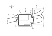
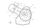
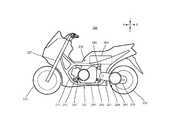
- FIG. 2 is a cross-sectional view taken along the line II of FIG. It is a left side view which shows the drive unit of the saddle type vehicle of FIG. It is sectional drawing in II-II of FIG. It is a top view which shows the drive unit of the saddle type vehicle of FIG. It is a right side view which shows the drive unit of the saddle type vehicle of FIG. It is a left side view which shows the modification of the arrangement of the generator and the power generation engine of the power generation unit of the saddle-type vehicle of FIG.
- FIG. 1 is a diagram showing a series hybrid saddle-mounted vehicle 1 according to the first embodiment of the present invention.
- Part (a) of FIG. 1 shows the appearance of the saddle-mounted vehicle 1 with the left body cover removed.
- Part (b) of FIG. 1 is a schematic cross-sectional view showing a power generation unit of the saddle-mounted vehicle 1.
- An outline of the series hybrid saddle-mounted vehicle 1 of the present embodiment will be described with reference to FIG.
- the arrow F in FIG. 1 indicates the forward direction in the series hybrid saddle-mounted vehicle 1.
- the forward direction is the direction in which the series hybrid saddle-mounted vehicle 1 travels.
- the arrow B indicates the backward direction.
- the arrows F and B represent the front-rear direction FB in the series hybrid saddle-mounted vehicle 1.
- the front direction F, the rear direction B, and the front-rear direction FB are parallel to the horizontal plane in the upright state of the series hybrid saddle-mounted vehicle 1.
- the arrow U indicates an upward direction.
- the arrow D indicates a downward direction.
- the arrows U and D represent the vertical UD in the series hybrid saddle-mounted vehicle 1.
- the upward direction U, the downward direction D, and the vertical direction UD are parallel to the vertical direction of the series hybrid saddle-mounted vehicle 1 in the upright state.
- the right and left directions of the rider in the lean vehicle are indicated by arrows L and R shown in part (b) of FIG.
- the arrow L and the arrow R represent the left-right direction LR in the series hybrid saddle-mounted vehicle 1.
- a generator is driven by a power generation engine, and drive wheels are driven by the electric power of the generator.
- the saddle-mounted vehicle 1 of FIG. 1 includes a frame structure 10.
- the frame structure 10 is composed of a frame body 11. That is, the saddle-mounted vehicle 1 of FIG. 1 includes a frame body 11.
- the saddle-mounted vehicle 1 includes a front fork 21 and front wheels 22.
- the front wheel 22 is rotatably supported by the front fork 21.
- the front fork 21 is rotatably supported by the frame structure 10.
- the frame structure 10 receives a load from the front wheels 22 via the front fork 21.
- the saddle-mounted vehicle 1 includes a rear arm 31 and a rear wheel 32.
- the rear wheel 32 is rotatably supported by the rear arm 31.
- the rear arm 31 is swingably supported by the frame structure 10.
- the frame structure 10 receives a load from the rear wheels 32 via the rear arm 31.
- the saddle-mounted vehicle 1 includes a drive motor 51.
- the drive motor 51 drives the rear wheels 32.
- the rear wheel 32 is a driving wheel. That is, the drive motor 51 drives the drive wheels.
- the saddle-mounted vehicle 1 includes a control unit 52.
- the control unit 52 controls the electric power supplied from the power generation unit 40 to the drive motor 51. Further, the control unit 52 controls the electric power supplied from the generator 42 to the battery 60.
- the saddle-mounted vehicle 1 includes a gearbox 53.
- the gearbox 53 accommodates a gear that shifts the rotational power from the drive motor 51 according to a predetermined gear ratio and transmits it to the rear wheels 32, which are the drive wheels.
- the gearbox 53 is rigidly fixed to the frame body 11.
- the gearbox 53 is integrated with the frame body 11 to form the frame structure 10.
- the gearbox 53 supports the drive motor 51. That is, the drive motor 51 is supported by the frame structure 10.
- the drive motor 51, the control unit 52, and the gearbox 53 constitute the drive unit 50.
- the saddle-mounted vehicle 1 includes a power generation engine 41 and a generator 42.
- the power generation engine 41 and the generator 42 form a power generation unit 40.
- the power generation unit 40 is supported by the frame body 11 so as not to form the frame structure 10.
- the power generation unit 40 is not supported by the rear arm 31.
- the power generation engine 41 has a rotatable crankshaft 411 (not shown).
- the power generation engine 41 outputs the power generated by the combustion of gas as the torque and rotation speed of the crankshaft 411.
- the power generation engine 41 is a saddle-type vehicle in the left-right direction LR of a saddle-type vehicle 1 composed of a first direction and a second direction opposite to the first direction.
- the power generation engine 41 is arranged at a position that does not overlap with the drive motor 51 in the left-right direction LR of the saddle-mounted vehicle 1. More specifically, in the present embodiment, as shown in the part (b) of FIG. 1, the center 41c of the power generation engine 41 is from the center 1c of the saddle-type vehicle in the left-right direction LR of the saddle-type vehicle 1. It is arranged so as to be offset to the right R. Further, the power generation engine 41 is arranged in front of the drive motor 51 in the front-rear direction FB of the saddle-mounted vehicle 1.
- the generator 42 is provided so as to interlock with the crankshaft 411.
- the generator 42 is driven by the power generation engine 41 and generates electric power for driving the drive motor 51.
- the generator 42 is located in a second direction from the power generation engine 41, has an overlap with the power generation engine 41 in the left-right direction LR, and does not overlap with the drive motor 51 in the left-right direction LR. Is placed in. More specifically, in the present embodiment, the generator 42 is located to the left of the power generation engine 41, has an overlap with the power generation engine 41 in the left-right direction LR, and is in the left-right direction LR. It is arranged so as not to overlap with the drive motor 51. That is, the generator 42 is arranged in front of the drive motor 51 in the front-rear direction FB of the saddle-mounted vehicle 1.
- the saddle-mounted vehicle 1 is equipped with a battery 60.
- the battery 60 stores the electric power generated by the generator 42 and supplies the stored electric power to the drive motor 51.
- the battery 60 is arranged above the gearbox 53.
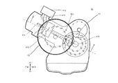
- FIG. 2 is a left side view showing the power generation unit 40 of the saddle-mounted vehicle 1 of FIG.
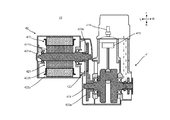
- FIG. 3 is a cross-sectional view taken along the line II of FIG.
- the power generation unit 40 includes a power generation engine 41 and a generator 42.
- the power generation engine 41 is provided with a throttle valve 412, a fuel injection device 413, and a spark plug 414.
- the throttle valve 412 regulates the amount of air supplied to the combustion chamber.
- the fuel injection device 413 supplies fuel to the air supplied to the combustion chamber by the throttle valve 412.
- a mixed gas of air and fuel is supplied to the combustion chamber.
- the fuel supply by the fuel injection device 413 and the opening degree of the throttle valve 412 are adjusted according to the amount of electric power required for the saddle-mounted vehicle 1 to travel.
- the spark plug 414 burns a mixture of air and fuel supplied to the combustion chamber.
- the power generation engine 41 is an internal combustion engine.
- the power generation engine 41 receives fuel supply.
- the power generation engine 41 outputs rotational power by a combustion operation of burning a mixed gas of fuel and air.
- the throttle valve 412 and the fuel injection device 413 adjust the rotational power output from the power generation engine 41 by adjusting the amounts of air and fuel supplied.
- the throttle valve 412 and the fuel injection device 413 function as a rotational power adjusting device that adjusts the rotational power output from the power generation engine 41.
- the power generation engine 41 has a rotatable crankshaft 411.
- the power generation engine 41 outputs rotational power via the crankshaft 411.
- the rotational power of the crankshaft 411 is converted into electric power by the generator 42.
- the electric power converted by the generator 42 is supplied to the drive motor 51 (see FIG. 1) and output again as rotational power.
- the rotational power output by the drive motor 51 is transmitted to the rear wheels 32.
- the power generation engine 41 does not directly drive the rear wheels 32. That is, the power of the power generation engine 41 is not directly transmitted to the rear wheels 32.
- the generator 42 is a permanent magnet type three-phase brushless generator.
- the generator 42 has a rotor 421 and a stator 422.
- the generator 42 of this embodiment is a radial gap type.
- the generator 42 is an inner rotor type. That is, the rotor 421 is an inner rotor.
- the stator 422 is an outer stator.
- the rotor 421 has a driven shaft 421a and a plurality of permanent magnet portions 421b.
- the plurality of permanent magnet portions 421b are provided on the outer peripheral surface of the driven shaft 421a.
- the plurality of permanent magnet portions 421b are provided so that the north pole and the south pole are alternately arranged in the circumferential direction of the generator 42.
- the plurality of permanent magnet portions 421b are provided closer to the center than the stator 422 in the radial direction of the generator 42.
- the rotor 421 is not provided with a winding to which a current is supplied.
- the stator 422 has a stator core 422a and a plurality of phase stator windings 422b.
- the stator core 422a has a cylindrical yoke and a plurality of tooth portions provided so as to extend inward at intervals in the circumferential direction of the yoke.
- the stator winding 422b is wound around each of the plurality of teeth.
- Each of the plurality of stator windings 422b belongs to any of U-phase, V-phase, and W-phase.
- the stator windings 422b are arranged so as to be arranged in the order of, for example, U phase, V phase, and W phase.
- the generator 42 is arranged at the left L position with respect to the power generation engine 41 in the left-right direction LR.
- the generator 42 is arranged so as to have an overlap with the power generation engine 41 when viewed from the left-right direction LR.
- the generator 42 is arranged so that the driven shaft 421a of the generator 42 and the crankshaft 411 of the power generation engine 41 are substantially parallel to each other.
- the driven shaft 421a of the generator 42 is connected to the crankshaft 411 via the drive gear 423a and the driven gear 423b, which are power transmission mechanisms, so as to interlock with the crankshaft 411 of the power generation engine 41.
- the rotor 421 is connected to the crankshaft 411 so as to rotate at a fixed speed ratio with respect to the crankshaft 411.
- the generator 42 is driven by the power generation engine 41 to generate power.
- the piston 13 of the power generation engine 41 moves up and down by the combustion operation to rotate the crankshaft 411.
- the drive gear 423a attached to the crankshaft 411 of the power generation engine 41 transmits the rotational power of the crankshaft 411 to the driven gear 423b attached to the driven shaft 421a of the generator 42.
- the generator 42 generates electricity by rotating the rotor 421 inward in the stator 422 in conjunction with the crankshaft 411.
- the power generation unit 40 does not form the frame structure 10, but is supported by the frame structure 10 by a floating mount. Specifically, the power generation unit 40 is supported by the frame body 11 and the gearbox 53 of the frame structure 10. The power generation unit 40 is supported by the frame body 11 and the gearbox 53 at four points of the frame body 11 and the gearbox 53 via a fixture 43 (see FIG. 1) including an elastic member such as a rubber bush and a link member. To. The power generation unit 40 may be supported by the frame body 11 and the gearbox 53 via an elastic member such as rubber. By attaching the power generation unit 40 to the frame body 11 and the gearbox 53 in this way, it is possible to suppress the transmission of the vibration of the power generation engine to the frame structure 10.
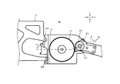
- FIG. 4 is a left side view showing the drive unit 50 of the saddle-mounted vehicle 1 of FIG.
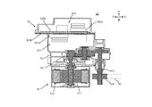
- FIG. 5 is a cross-sectional view taken along the line II-II of FIG.
- FIG. 6 is a top view showing the drive unit 50 of the saddle-mounted vehicle 1 of FIG.
- FIG. 7 is a right side view showing the drive unit 50 of the saddle-mounted vehicle 1 of FIG.
- the drive unit 50 includes a drive motor 51, a control unit 52, and a gearbox 53.
- the drive motor 51 is a permanent magnet type three-phase brushless motor.
- the drive motor 51 also functions as a permanent magnet type three-phase brushless generator.
- the drive motor 51 is a radial gap type having an inner rotor 511 and an outer stator 512.
- the drive motor 51 drives the rear wheels 32 (see FIG. 1) as a vehicle drive motor. At this time, the drive motor 51 receives power from at least one of the generator 42 (see FIG. 2) and the battery 60 (see FIG. 1) of the power generation unit 40.
- the drive motor 51 outputs rotational power from the supplied electric power to drive the rear wheels 32 via the power transmission mechanism 531 of the gearbox 53.
- the control unit 52 includes a drive control unit 521 and a power supply control unit 522.
- the drive control unit 521 includes an inverter module 521a including an inverter and a motor controller, and a mounting board 521b.
- the inverter module 521a is mounted on the mounting board 521b of the drive control unit 521.
- the power control unit 522 includes a converter module 522a including a converter and a power generation controller, and a mounting board 522b.
- the converter module 522a is mounted on the mounting board 522b of the power supply control unit 522.
- the mounting board 522b may be the same as or separate from the mounting board 521b of the drive control unit 521.
- the drive motor 51 of the drive unit 50, the battery 60, and the converter module 522a of the power supply control unit 522 are connected to the inverter module 521a of the drive control unit 521.
- the motor controller of the inverter module 521a controls the operation of the drive motor 51 by controlling the on / off operation of each of the plurality of switching units of the inverter.
- the generator 42 of the power generation unit 40 and the battery 60 are connected to the converter module 522a of the power supply control unit 522.
- the power generation controller of the converter module 522a controls the converter to rectify the three-phase alternating current output from the generator 42 and control the voltage.
- the gearbox 53 houses the power transmission mechanism 531 and the output shaft 534.
- a drive pulley 535 is attached to the output shaft 534.
- the power transmission mechanism 531 constitutes, for example, a speed reducer.
- the power transmission mechanism 531 decelerates the power output from the drive motor 51 by a predetermined gear ratio and transmits it to the rear wheels 32. Specifically, the rotational power from the drive motor 51 is decelerated by the power transmission mechanism 531 which is a speed reducer and is transmitted to the output shaft 534.
- the rotational power transmitted to the output shaft 534 is transmitted to the drive shaft of the rear wheels 32, which are the drive wheels, via the drive pulley 535 and the belt chain 54.
- the gearbox 53 is rigidly fixed to the rear end of the frame body 11 at at least 3 points, for example, 4 points in the present embodiment in the front-rear direction FB of the saddle-mounted vehicle 1 including the front direction F and the rear direction B. Will be done.
- the frame main body 11 is fixed in contact with the gearbox 53 at four points of the mounting portions 561 to 564 of the gearbox 53 of FIGS. 4 to 7 without using an elastic member such as rubber.
- the mounting portion 561 is provided at the upper left portion of the gearbox 53, and the mounting portion 562 is provided at the lower left portion of the gearbox 53.
- the mounting portion 563 is provided in the upper right portion of the gearbox 53, and the mounting portion 564 is provided in the lower right portion of the gearbox 53.
- a support method for example, it is fixed with bolts.
- the gearbox 53 is rigidly fixed to the frame body 11, the frame structure 10 is integrally formed with the frame body 11. As a result, the gearbox 53, together with the frame body 11, forms the skeleton of the saddle-mounted vehicle 1 and can receive the loads from the front wheels 22, the rear wheels 32, and the power generation unit 40.
- the rear arm 31 is swingably supported by the gearbox 53 at two points of mounting portions 571 and 572 provided in the gearbox 53 of FIGS. 4 to 7.
- the mounting portion 571 is provided on the left portion of the gearbox 53
- the mounting portion 572 is provided on the right portion of the gearbox 53.
- the output shaft 534 of the power transmission mechanism 531 penetrates the mounting portion 571 and the rear arm 31.
- the mounting bolt 573 (see FIG. 7) penetrates the rear arm 31 and is inserted into the mounting portion 572 of the gearbox.
- the frame structure 10 and the rear arm 31 are connected by a damping device (not shown).
- the damping device absorbs the vibration from the rear arm 31. As a result, the vibration transmitted from the rear wheel 32 to the frame structure 10 via the rear arm 31 is reduced.
- the power generation unit 40 having the generator 42 and the power generation engine 41 is supported not by the rear arm 31 but by the frame structure 10.
- the power generation engine 41 shifts from the center of the series hybrid saddle-type vehicle 1 in the left-right direction LR to the right direction R, and the generator 42 is to the left of the power generation engine. It is located at L. Therefore, the generator 42 and the power generation engine 41 can be arranged so as to have an overlap in the left-right direction LR while suppressing the amount of protrusion of the generator 42 in the left direction L.
- the power generation engine 41 and the generator 42 of the series hybrid saddle-mounted vehicle 1 have been increased in size so as to cope with the increase in the electric power that can be supplied to the drive motor 51.
- the generator 42 and the power generation engine 41 are arranged so as to have an overlap when viewed in the left-right direction LR. Therefore, the increase in the dimensions of the entire power generation unit 40 in the vertical UD front and rear FB directions can be made smaller than the sum of the dimensional increase in the power generation engine 41 and the dimensional increase in the generator 42. Therefore, even when both the power generation engine 41 and the generator 42 are enlarged due to the increase in output, the increase in size of the power generation unit 40 in the vertical UD front and rear FB directions is suppressed.
- the size of the power generation unit 40 in the vertical UD front and rear FB directions has a large effect on the wheelbase and frame size of the series hybrid saddle-mounted vehicle 1.
- the increase in size of the vehicle can be suppressed.
- FIG. 8 is a diagram showing a modified example of the arrangement of the generator 42 and the power generation engine 41.
- the generator 42 may be directly connected to the crankshaft 411 of the power generation engine 41 without passing through the drive gear 423a and the driven gear 423b, which are power transmission mechanisms.
- the driven shaft 421a of the generator 42 and the crankshaft 411 of the power generation engine are arranged on the unified axis c.
- FIG. 9 is an external view showing a saddle-mounted vehicle 100 according to a second embodiment of the present invention.
- FIG. 9 shows a state in which the vehicle body cover in the left direction is removed in the left-right direction LR of the saddle-mounted vehicle 100.
- the saddle-mounted vehicle 100 according to the present embodiment and the saddle-mounted vehicle 1 according to the first embodiment are different in the support method of the power generation unit 140.
- the present embodiment and the first embodiment will be described.
- the power generation unit 140 is rigidly fixed to the frame structure 110. Specifically, the power generation unit 140 is supported by the frame body 111 of the frame structure 110. The power generation unit 140 is attached in contact with the frame body 111 at at least three points of the frame body 111 without using an elastic member such as rubber. Since the power generation unit 140 is rigidly fixed to the frame body 111, the frame structure 110 is integrally formed with the frame body 111 and the drive unit 150. As a result, the power generation unit 140, together with the frame body 111 and the drive unit 150, forms the skeleton of the saddle-mounted vehicle 100 and can receive the loads from the front wheels 122 and the rear wheels 132.
- FIG. 10 is an external view showing a saddle-mounted vehicle 200 according to a third embodiment of the present invention.
- FIG. 10 shows a state in which the left body cover is removed.
- the saddle-mounted vehicle 200 according to the present embodiment and the saddle-mounted vehicle 1 according to the first embodiment are different in the support method of the power generation unit 240, the configuration of the drive unit, and the support method between the frame main body and the drive unit.
- the present embodiment and the first embodiment will be described.
- the drive unit 250 includes a drive motor 251 and a gearbox 253.
- the gearbox 253 constitutes the rear arm 231. Further, the drive motor 251 is attached to the gearbox 253.
- the gearbox 253 is supported by the frame body 211 as a rear arm 231 so as to be integrally swingable with the drive motor 251. Therefore, in the present embodiment, the drive unit 250 does not form the frame structure 210. That is, in the present embodiment, the frame structure 210 is composed of only the frame body 211.
- the power generation unit 240 is supported by the frame body 211 of the frame structure 210 via a fixture 243 including an elastic member such as a rubber bush and a link member.
- the power generation unit 240 may be supported by the frame body 211 of the frame structure 210 via an elastic member such as rubber.
- the drive unit 250 can be configured not to include the gearbox 253.
- the drive motor 251 is attached to the rear arm 231 and the central shaft of the rear wheel 232 is directly connected to the output shaft of the drive motor 251. That is, the drive motor 251 is configured as an in-wheel motor of the rear wheel 232.
- FIG. 11 is an external view showing a saddle-mounted vehicle 300 according to a fourth embodiment of the present invention.
- FIG. 11 shows a state in which the left body cover is removed.
- the saddle-mounted vehicle 300 according to the present embodiment and the saddle-mounted vehicle 1 according to the first embodiment are described in the method of supporting the power generation unit 340, the configuration of the drive unit 350, and the method of supporting the frame body 311 and the drive unit 350. different.
- the present embodiment and the first embodiment will be described.
- the power generation unit 340 is rigidly fixed to the frame structure 310. Specifically, the power generation unit 340 is supported by the frame body 311 of the frame structure 310. In the support method, the power generation unit 340 is attached in contact with the frame body 311 at at least three points or more of the frame body 311 without using an elastic member such as rubber. Since the power generation unit 340 is rigidly fixed to the frame body 311, the frame structure 310 is integrally formed with the frame body 111. As a result, the power generation unit 340, together with the frame body 311 can form the skeleton of the saddle-mounted vehicle 300 and can receive the loads from the front wheels 322 and the rear wheels 332.
- the drive unit 350 includes a drive motor 351 and a gearbox 353.
- the gearbox 353 constitutes the rear arm 331.
- the drive motor 351 is attached to the gearbox 353.
- the gearbox 353 is supported as the rear arm 331 by the frame body 311 so as to be integrally with the drive motor 351 and swingably. Therefore, in the present embodiment, the drive unit 350 does not form the frame structure 310. That is, in the present embodiment, the frame structure 310 is composed of the frame body 311 and the power generation unit 340.
- control unit 352 may or may not be included in the drive unit 350. Although the arrangement position of the control unit 352 is not specified in FIG. 11, in the present embodiment, the control unit 352 may form a rear arm integrally with the drive unit 350, or the saddle-mounted vehicle 1 may be formed. It may be attached to the frame structure 310.
- the drive unit 350 can be configured not to include the gearbox 353.
- the drive motor 351 is attached to the rear arm 331, and the central shaft of the rear wheel 332 is directly connected to the output shaft of the drive motor 351. That is, the drive motor 351 is configured as an in-wheel motor for the rear wheels 332.
Landscapes
- Engineering & Computer Science (AREA)
- Mechanical Engineering (AREA)
- Chemical & Material Sciences (AREA)
- Combustion & Propulsion (AREA)
- Transportation (AREA)
- Electric Propulsion And Braking For Vehicles (AREA)
- Hybrid Electric Vehicles (AREA)
- Automatic Cycles, And Cycles In General (AREA)
- Axle Suspensions And Sidecars For Cycles (AREA)
Priority Applications (3)
| Application Number | Priority Date | Filing Date | Title |
|---|---|---|---|
| EP20790749.4A EP3950476B1 (en) | 2019-04-19 | 2020-04-14 | Series hybrid type straddled vehicle |
| JP2021514163A JP7258126B2 (ja) | 2019-04-19 | 2020-04-14 | シリーズハイブリッド式ストラドルドビークル |
| US17/504,837 US12275306B2 (en) | 2019-04-19 | 2021-10-19 | Series hybrid type straddled vehicle |
Applications Claiming Priority (2)
| Application Number | Priority Date | Filing Date | Title |
|---|---|---|---|
| JP2019080271 | 2019-04-19 | ||
| JP2019-080271 | 2019-04-19 |
Related Child Applications (1)
| Application Number | Title | Priority Date | Filing Date |
|---|---|---|---|
| US17/504,837 Continuation-In-Part US12275306B2 (en) | 2019-04-19 | 2021-10-19 | Series hybrid type straddled vehicle |
Publications (1)
| Publication Number | Publication Date |
|---|---|
| WO2020213593A1 true WO2020213593A1 (ja) | 2020-10-22 |
Family
ID=72837815
Family Applications (1)
| Application Number | Title | Priority Date | Filing Date |
|---|---|---|---|
| PCT/JP2020/016386 Ceased WO2020213593A1 (ja) | 2019-04-19 | 2020-04-14 | シリーズハイブリッド式ストラドルドビークル |
Country Status (4)
| Country | Link |
|---|---|
| US (1) | US12275306B2 (cg-RX-API-DMAC7.html) |
| EP (1) | EP3950476B1 (cg-RX-API-DMAC7.html) |
| JP (1) | JP7258126B2 (cg-RX-API-DMAC7.html) |
| WO (1) | WO2020213593A1 (cg-RX-API-DMAC7.html) |
Cited By (2)
| Publication number | Priority date | Publication date | Assignee | Title |
|---|---|---|---|---|
| EP4116179A1 (en) * | 2021-07-08 | 2023-01-11 | Kawasaki Motors, Ltd. | Geared motor for vehicle |
| EP4661259A4 (en) * | 2023-02-01 | 2026-05-13 | Jatco Ltd | UNIT |
Families Citing this family (1)
| Publication number | Priority date | Publication date | Assignee | Title |
|---|---|---|---|---|
| WO2021205467A1 (en) * | 2020-04-09 | 2021-10-14 | Tvs Motor Company Limited | A vehicle |
Citations (10)
| Publication number | Priority date | Publication date | Assignee | Title |
|---|---|---|---|---|
| JPH1159543A (ja) * | 1997-08-28 | 1999-03-02 | Yamaha Motor Co Ltd | 自動二輪車の車体フレーム |
| JP2005132284A (ja) * | 2003-10-31 | 2005-05-26 | Yamaha Motor Co Ltd | 電動車両 |
| JP2007008349A (ja) * | 2005-06-30 | 2007-01-18 | Yamaha Motor Co Ltd | ハイブリッド車両 |
| JP3942772B2 (ja) | 1999-10-08 | 2007-07-11 | ヤマハ発動機株式会社 | シリーズハイブリッド式電動二輪車 |
| JP2007209188A (ja) * | 2006-02-01 | 2007-08-16 | Ikedo Yosetsu Seisakusho:Kk | 発電機移送用車両 |
| JP2012111278A (ja) * | 2010-11-22 | 2012-06-14 | Yamaha Motor Co Ltd | 自動二輪車 |
| WO2012090243A1 (ja) * | 2010-12-27 | 2012-07-05 | 川崎重工業株式会社 | 電動二輪車 |
| JP2015085797A (ja) * | 2013-10-30 | 2015-05-07 | スズキ株式会社 | 電動二輪車 |
| JP2018012346A (ja) * | 2015-10-02 | 2018-01-25 | ヤマハ発動機株式会社 | ビークル、及びビークル駆動用エンジン発電ユニット |
| JP2019506333A (ja) * | 2016-02-25 | 2019-03-07 | 本田技研工業株式会社 | 自動二輪車用のフレーム構造 |
Family Cites Families (9)
| Publication number | Priority date | Publication date | Assignee | Title |
|---|---|---|---|---|
| JP3660466B2 (ja) * | 1997-05-01 | 2005-06-15 | ヤマハ発動機株式会社 | ハイブリッド式二輪車 |
| JP4400777B2 (ja) * | 2003-03-12 | 2010-01-20 | ヤマハ発動機株式会社 | スクータ型自動二輪車 |
| WO2005063559A1 (ja) * | 2003-12-25 | 2005-07-14 | Yamaha Hatsudoki Kabushiki Kaisha | 電動車両 |
| JP4005062B2 (ja) | 2004-08-05 | 2007-11-07 | 本田技研工業株式会社 | ハイブリッド車両の動力切換装置 |
| JP2006347427A (ja) * | 2005-06-17 | 2006-12-28 | Yamaha Motor Co Ltd | ハイブリッド式鞍乗型車両 |
| CN102822049B (zh) * | 2010-03-23 | 2015-04-29 | 本田技研工业株式会社 | 混合动力式骑乘型车辆 |
| WO2011121785A1 (ja) * | 2010-03-31 | 2011-10-06 | 本田技研工業株式会社 | ハイブリッド式パワーユニット |
| EP3206292B8 (en) | 2014-11-25 | 2020-02-26 | Yamaha Hatsudoki Kabushiki Kaisha | Electric current supply system, electric power supply system, and control device |
| JP6370736B2 (ja) | 2015-03-31 | 2018-08-08 | 株式会社シマノ | 自転車用ドライブユニット、および、このドライブユニットを備える自転車 |
-
2020
- 2020-04-14 EP EP20790749.4A patent/EP3950476B1/en active Active
- 2020-04-14 JP JP2021514163A patent/JP7258126B2/ja active Active
- 2020-04-14 WO PCT/JP2020/016386 patent/WO2020213593A1/ja not_active Ceased
-
2021
- 2021-10-19 US US17/504,837 patent/US12275306B2/en active Active
Patent Citations (10)
| Publication number | Priority date | Publication date | Assignee | Title |
|---|---|---|---|---|
| JPH1159543A (ja) * | 1997-08-28 | 1999-03-02 | Yamaha Motor Co Ltd | 自動二輪車の車体フレーム |
| JP3942772B2 (ja) | 1999-10-08 | 2007-07-11 | ヤマハ発動機株式会社 | シリーズハイブリッド式電動二輪車 |
| JP2005132284A (ja) * | 2003-10-31 | 2005-05-26 | Yamaha Motor Co Ltd | 電動車両 |
| JP2007008349A (ja) * | 2005-06-30 | 2007-01-18 | Yamaha Motor Co Ltd | ハイブリッド車両 |
| JP2007209188A (ja) * | 2006-02-01 | 2007-08-16 | Ikedo Yosetsu Seisakusho:Kk | 発電機移送用車両 |
| JP2012111278A (ja) * | 2010-11-22 | 2012-06-14 | Yamaha Motor Co Ltd | 自動二輪車 |
| WO2012090243A1 (ja) * | 2010-12-27 | 2012-07-05 | 川崎重工業株式会社 | 電動二輪車 |
| JP2015085797A (ja) * | 2013-10-30 | 2015-05-07 | スズキ株式会社 | 電動二輪車 |
| JP2018012346A (ja) * | 2015-10-02 | 2018-01-25 | ヤマハ発動機株式会社 | ビークル、及びビークル駆動用エンジン発電ユニット |
| JP2019506333A (ja) * | 2016-02-25 | 2019-03-07 | 本田技研工業株式会社 | 自動二輪車用のフレーム構造 |
Non-Patent Citations (1)
| Title |
|---|
| See also references of EP3950476A4 |
Cited By (5)
| Publication number | Priority date | Publication date | Assignee | Title |
|---|---|---|---|---|
| EP4116179A1 (en) * | 2021-07-08 | 2023-01-11 | Kawasaki Motors, Ltd. | Geared motor for vehicle |
| JP2023009887A (ja) * | 2021-07-08 | 2023-01-20 | カワサキモータース株式会社 | 車両のギア付きモータ |
| US11926391B2 (en) | 2021-07-08 | 2024-03-12 | Kawasaki Motors, Ltd. | Geared motor for vehicle |
| JP7663437B2 (ja) | 2021-07-08 | 2025-04-16 | カワサキモータース株式会社 | 車両のギア付きモータ |
| EP4661259A4 (en) * | 2023-02-01 | 2026-05-13 | Jatco Ltd | UNIT |
Also Published As
| Publication number | Publication date |
|---|---|
| JPWO2020213593A1 (cg-RX-API-DMAC7.html) | 2020-10-22 |
| JP7258126B2 (ja) | 2023-04-14 |
| US20220032765A1 (en) | 2022-02-03 |
| US12275306B2 (en) | 2025-04-15 |
| EP3950476B1 (en) | 2024-12-11 |
| EP3950476A1 (en) | 2022-02-09 |
| EP3950476A4 (en) | 2022-06-08 |
Similar Documents
| Publication | Publication Date | Title |
|---|---|---|
| US12187129B2 (en) | Straddled vehicle | |
| US12275306B2 (en) | Series hybrid type straddled vehicle | |
| US20220033027A1 (en) | Straddled vehicle | |
| JP5293883B2 (ja) | ハイブリッド式鞍乗り型車両 | |
| CN103359254B (zh) | 电动车辆 | |
| US20130288841A1 (en) | Vehicle drive unit | |
| JP3159814U (ja) | ハイブリッド式鞍乗型車両 | |
| JP2006256468A (ja) | ハイブリッド車両の駆動ユニット、ハイブリッド車両及び二輪車 | |
| US8424626B2 (en) | Vehicle | |
| CN1836962A (zh) | 跨乘式混合动力车 | |
| JP2010100124A (ja) | ハイブリッド式鞍乗型車両 | |
| US7140458B2 (en) | Battery arrangement and battery mounting structure for a vehicle | |
| CN105122612A (zh) | 发电电动单元、动力输出机关、以及车辆 | |
| WO2020213590A1 (ja) | シリーズハイブリッド式ストラドルドビークル | |
| JP2011073620A (ja) | ハイブリッド式車両 | |
| JP2020175822A (ja) | シリーズハイブリッド式鞍乗型車両 | |
| CN101058331A (zh) | 混合型车辆 | |
| JPWO2020194951A1 (ja) | 鞍乗型電動車両 | |
| JP7552891B2 (ja) | 駆動ユニット | |
| US7210851B2 (en) | Arrangement structure of bearings | |
| WO2019004052A1 (ja) | 鞍乗型電動車両 | |
| JP5026950B2 (ja) | 車両の駆動装置 | |
| JP7387921B2 (ja) | シリーズハイブリッド式ストラドルドビークル | |
| JPS61187533A (ja) | 自動二輪車のエンジン回り構造 | |
| JP2004120912A (ja) | インホイールモータのボビン支持構造 |
Legal Events
| Date | Code | Title | Description |
|---|---|---|---|
| 121 | Ep: the epo has been informed by wipo that ep was designated in this application |
Ref document number: 20790749 Country of ref document: EP Kind code of ref document: A1 |
|
| ENP | Entry into the national phase |
Ref document number: 2021514163 Country of ref document: JP Kind code of ref document: A |
|
| NENP | Non-entry into the national phase |
Ref country code: DE |
|
| ENP | Entry into the national phase |
Ref document number: 2020790749 Country of ref document: EP Effective date: 20211102 |