WO2020209362A1 - Outil d'ajout de vibrations ultrasonores - Google Patents
Outil d'ajout de vibrations ultrasonores Download PDFInfo
- Publication number
- WO2020209362A1 WO2020209362A1 PCT/JP2020/016129 JP2020016129W WO2020209362A1 WO 2020209362 A1 WO2020209362 A1 WO 2020209362A1 JP 2020016129 W JP2020016129 W JP 2020016129W WO 2020209362 A1 WO2020209362 A1 WO 2020209362A1
- Authority
- WO
- WIPO (PCT)
- Prior art keywords
- ultrasonic vibration
- peripheral surface
- cylindrical
- vibration imparting
- ring
- Prior art date
Links
- 230000002093 peripheral effect Effects 0.000 claims description 32
- 229910000831 Steel Inorganic materials 0.000 claims description 2
- 239000000463 material Substances 0.000 claims description 2
- 230000000149 penetrating effect Effects 0.000 claims description 2
- 239000010959 steel Substances 0.000 claims description 2
- 238000012545 processing Methods 0.000 description 9
- 239000002184 metal Substances 0.000 description 4
- 230000005540 biological transmission Effects 0.000 description 2
- 238000011160 research Methods 0.000 description 2
- 241000251468 Actinopterygii Species 0.000 description 1
- 239000006061 abrasive grain Substances 0.000 description 1
- 230000002411 adverse Effects 0.000 description 1
- 238000000889 atomisation Methods 0.000 description 1
- 238000005452 bending Methods 0.000 description 1
- 238000004891 communication Methods 0.000 description 1
- 238000005520 cutting process Methods 0.000 description 1
- 238000011161 development Methods 0.000 description 1
- 238000010586 diagram Methods 0.000 description 1
- 239000006185 dispersion Substances 0.000 description 1
- 230000000694 effects Effects 0.000 description 1
- 238000004945 emulsification Methods 0.000 description 1
- 238000005516 engineering process Methods 0.000 description 1
- 239000007769 metal material Substances 0.000 description 1
- 238000000034 method Methods 0.000 description 1
- 238000004023 plastic welding Methods 0.000 description 1
- 230000010287 polarization Effects 0.000 description 1
- 238000005498 polishing Methods 0.000 description 1
- 238000002360 preparation method Methods 0.000 description 1
- 239000011343 solid material Substances 0.000 description 1
- 238000004506 ultrasonic cleaning Methods 0.000 description 1
Images


Classifications
-
- H—ELECTRICITY
- H04—ELECTRIC COMMUNICATION TECHNIQUE
- H04R—LOUDSPEAKERS, MICROPHONES, GRAMOPHONE PICK-UPS OR LIKE ACOUSTIC ELECTROMECHANICAL TRANSDUCERS; DEAF-AID SETS; PUBLIC ADDRESS SYSTEMS
- H04R17/00—Piezoelectric transducers; Electrostrictive transducers
- H04R17/10—Resonant transducers, i.e. adapted to produce maximum output at a predetermined frequency
Definitions
- the present invention relates to an ultrasonic vibration imparting tool using a Langevin type ultrasonic oscillator. Background technology
- ultrasonic vibrators using a piezoelectric element as an ultrasonic wave generator are known and are used as ultrasonic vibration imparting tools.
- a Langevin type ultrasonic oscillator composed of a pair of metal blocks and a polarized piezoelectric element fixed between these metal blocks is known. ..
- the bolted Langevin type ultrasonic vibrator which has a structure in which polarized piezoelectric elements are connected by bolts between a pair of metal blocks and tightened and fixed at high pressure, can generate high-energy ultrasonic vibrations.
- ultrasonic processing which is attached to tools for polishing, cutting, plastic working, abrasive grain processing, etc. of various solid materials
- ultrasonic cleaning, metal bonding, plastic welding, and ultrasonic waves are performed by transmitting the ultrasonic vibration generated by the ultrasonic vibrator via a vibrating plate or various vibrating means.
- Applications for ultrasonic processing such as atomization, emulsification / dispersion, and also for underwater acoustic devices (sonar) such as fish finder, ultrasonic flaw detectors, medical echo diagnostic devices, and communication application devices such as flow meters. It has been considered and is actually in use.
- Patent Document 1 is written on August 16, 2018, which is earlier than the filing date (April 11, 2019) of the Japanese patent application (JP2019-087885) in which the priority based on the Paris Convention is claimed in this patent application.
- the published PCT / JP2018 / 00428 international publication WO 2018/147445 A1 is shown in Patent Document 1 as FIG. 1 (prior art: PRIOR ART) in the attached drawings of the present application (FIG. 4).
- a cylindrical housing with a contact surface at the bottom or bottom of the inner peripheral surface and a threaded portion at the bottom of the outer peripheral surface; a disk with a contact surface that is fitted to the contact surface of the cylindrical housing.
- the invention of an ultrasonic vibration imparting tool including a ring-shaped balancing weight (ring-shaped vibration weight) having a screw portion on which the screw portion of the cylindrical housing is screwed is disclosed. Has been done.
- Patent Document 1 as a preferable configuration of the ring-shaped balancing weight, a lower small diameter portion having an inner diameter smaller than the inner diameter of the threaded portion is formed on the lower side of the threaded portion, and the lower small diameter portion thereof is formed.
- a configuration in which a gap is formed between the inner peripheral surface of the portion and the side surface of the cylindrical tool attachment (which also serves as the front mass) is also disclosed. Then, in FIGS. 4 and 8 and 9, the ultrasonic vibration imparting tool is supported (or held) by a supporting (or holding) member provided around or above the cylindrical housing. It is shown.
- Patent Document 1 states that when ultrasonic processing is performed using an ultrasonic processing apparatus incorporating the ultrasonic vibration imparting tool of the invention disclosed therein, the ultrasonic vibration energy generated by the ultrasonic vibration imparting tool is supported. Leakage to the member is significantly reduced, and therefore, the ultrasonic vibration generated by the Langevin type ultrasonic vibrator can be transmitted to the tool attached to the ultrasonic vibration imparting tool with high efficiency and high stability. There is a statement to the effect that it will be possible.
- Patent Document 1 WO 2018/147445 A1 (International Publication of PCT / JP2018 / 00428)
- Patent Document 1 The inventor of the present invention is the inventor of the invention disclosed in Patent Document 1, but in order to further improve the ultrasonic vibration imparting efficiency of the ultrasonic vibration imparting tool disclosed in Patent Document 1, Patent Document Improvement of the ultrasonic vibration imparting tool according to No. 1 (in particular, ultrasonic vibration imparting capable of transmitting ultrasonic vibration generated by a Langevin type ultrasonic vibrator to a tool or the like mounted on the front mass with higher efficiency. Since then, I have continued research aimed at (development of tools). Means to solve problems
- the inventor of the present invention considers the ultrasonic vibration imparting tool having the basic configuration described in Patent Document 1 as the ultrasonic vibration imparting tool when the configuration satisfies the conditions described below.
- the present invention has been reached by finding that the function of the above is further improved and the ultrasonic vibration imparting tool is more advantageous for industrial use.
- the ultrasonic vibration imparting tool provided by the present invention is an ultrasonic vibration imparting tool having the following configuration.
- Langeban type ultrasonic transducer and an ultrasonic vibration imparting tool including a ring-shaped balancing weight having a threaded portion on the upper part of the inner peripheral surface into which the threaded portion of the cylindrical housing is screwed, of the ring-shaped balancing weight.
- a small diameter portion (lower small diameter portion) having an inner diameter smaller than the inner diameter of the screw portion is formed on the lower side of the threaded portion, and between the inner peripheral surface of the lower small diameter portion and the side surface of the cylindrical front mass.
- the radius (Hin) of the circle formed by the inner peripheral surface of the cylindrical part of the cylindrical housing is the radius of the circle formed by the inner peripheral surface of the lower small diameter part of the ring-shaped equilibrium weight (Hin).
- the cylindrical housing is made of a metal material (particularly a steel material).
- the ultrasonic vibration imparting tool is supported (or held) by a supporting (or holding) member provided around or above the cylindrical housing.
- Three or more through holes penetrating from the outer peripheral surface to the inner peripheral surface are formed in the threaded portion (upper large diameter portion) of the ring-shaped balancing weight.
- a tool mounting opening is formed below the front mass.
- the ultrasonic vibration imparting tool of the present invention When the ultrasonic vibration imparting tool of the present invention is incorporated into an ultrasonic processing device or an ultrasonic transmission device via a support to generate ultrasonic vibration, the ultrasonic vibration generated by the Langevin type ultrasonic vibrator is supported. There is little leakage to the body, and it can be reliably and highly efficiently transmitted to the tools and vibrating bodies attached to the front mass. Therefore, it is possible to reduce the electric power energy required to drive the ultrasonic vibration device.
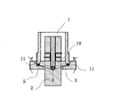
- FIG. 1 It is a front sectional view (vibration mode is also shown) which shows the structural example of the ultrasonic vibration imparting tool (the ultrasonic vibration imparting tool disclosed in Patent Document 1) belonging to the prior art (PRIOR ART). It is a top view of the example of the ultrasonic vibration imparting tool of this invention, and shows the state supported by the support member. It is a front sectional view of the ultrasonic vibration imparting tool (supported by a support member) shown in FIG. Vibration of the Langevin type ultrasonic oscillator generated when electric energy is applied to the ultrasonic vibration imparting device of the present invention shown in FIGS. 2 and 3, vibration of the flange portion of the front mass, and ring-shaped balanced weight.
- FIG. 4 shows a state in which the Langevin type ultrasonic oscillator is in a lowered position due to vibration.
- the vibration of the Langevin type ultrasonic oscillator constituting the ultrasonic vibration imparting tool of the present invention shown in FIG. 4 the vibration of the disk-shaped bulge (flange) of the columnar front mass, and the vibration of the ring-shaped equilibrium weight, respectively.
- FIG. 4 shows by a method different from FIG.
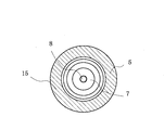
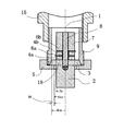
- FIGS. 2 and 3 are views showing a typical configuration example of the ultrasonic vibration imparting tool of the present invention, in which the ultrasonic vibration imparting tool supports (or holds) the ultrasonic vibration imparting tool provided around or above the cylindrical housing. Indicates a state of being supported (or held) by a member.
- the ultrasonic vibration imparting tool of the present invention shown in FIGS. 2 and 3 has a configuration similar to that of the ultrasonic vibration imparting tool disclosed in Patent Document 1.
- the ultrasonic vibration imparting tool 1 shown in FIGS. 2 and 3 is provided with a contact surface (contact surface with the end surface of the flange 3 formed on the upper portion of the front mass 2) at the lower portion or the bottom portion of the inner peripheral surface.
- the polarization-treated piezoelectric elements 4a and 4b are sandwiched between the cylindrical front mass 2 on which the is mounted and the cylindrical rear mass 7 arranged above the front mass 2 by the electrodes 6a and 6b, and the bolts 8 are used.
- a flange van type ultrasonic transducer 1 having a fixed configuration; and an ultrasonic vibration imparting tool including a ring-shaped balancing weight 5 having a threaded portion on the lower outer peripheral surface of the cylindrical housing 9 on the upper inner peripheral surface, which is a ring.
- a lower small diameter portion having an inner diameter smaller than the inner diameter of the threaded portion is formed on the lower side of the threaded portion of the balanced weight 5, and the inner peripheral surface of the lower small diameter portion and the side surface of the cylindrical front mass 2 are formed.
- a circle having a structure in which a gap is formed between them, and the radius (Hin) of the circle formed by the inner peripheral surface of the cylindrical portion of the cylindrical housing 9 is a ring-shaped equilibrium weight 5 formed by the inner peripheral surface of the lower small diameter portion.
- the radius (Fr) of the cylindrical front mass 2 at the position where (HN), which is larger than the radius (Nin) of the flange 3 and is the difference from the radius (that is, Hin-Nin), is in contact with the lower surface of the flange 3 is 0. It is an ultrasonic vibration imparting tool 1 which is 0.01 times or more and 1 times or less. Note that FIGS. 2 and 3 show a state in which the ultrasonic vibration imparting tool 1 is supported (or held) by a supporting (or holding) member 15 provided around or above the cylindrical housing 9.
- the ultrasonic vibration imparting tool of the present invention is an ultrasonic vibration imparting tool described in Patent Document 1 and having a basic configuration similar to that of the illustrated ultrasonic vibration imparting tool, but the cylindrical portion of the cylindrical housing.
- the radius (Hin) of the circle formed by the inner peripheral surface is larger than the radius (Nin) of the circle formed by the inner peripheral surface of the lower small diameter portion of the ring-shaped equilibrium weight, and the difference from the radius (that is, Hin-Nin).
- the ultrasonic vibration imparting tool of the present invention has a basic configuration similar to that of the ultrasonic vibration imparting tool described in Patent Document 1 and shown, but within the cylindrical portion of the cylindrical housing.
- the radius (Hin) of the circle formed by the peripheral surface is larger than the radius (Nin) of the circle formed by the inner peripheral surface of the lower small diameter portion of the ring-shaped equilibrium weight, and is the difference (Hin-Nin) from the radius.
- the difference is that (HN) is 0.01 times or more and 1 time or less of the radius (Fr) of the cylindrical front mass at the position in contact with the lower surface of the disk-shaped bulge (flange).
- the lower small diameter portion of the ring-shaped balancing weight that contacts the lower surface of the disk-shaped bulging portion (flange) is compared with the ultrasonic vibration imparting tool described in Patent Document 1.
- the contact area of the upper surface becomes large. Therefore, the ultrasonic vibration generated by the Langevin type ultrasonic oscillator and transmitted to the flange can be transmitted to the ring-shaped balanced weight with higher efficiency.
- FIGS. 4 and 5 are diagrams diagrammatically showing the transmission of the ultrasonic vibration transmitted to the flange to the ring-shaped balanced weight with high efficiency, respectively. That is, the vertical vibration (butterfly vibration) of the outer peripheral end of the ring-shaped balancing weight becomes large. Then, due to the vertical vibration (butterfly vibration) increased at the outer peripheral end portion, the bending vibration of the flange of the front mass in the vertical direction increases from the screw surface of the upper large diameter portion through the lower part of the housing, and as a result, The ultrasonic vibration in the vertical direction of the front mass increases. That is, the ultrasonic vibration in the vertical direction generated by the Langevin type ultrasonic vibrator is amplified and transmitted to the tool or the vibrating tool equipped with the front mass.
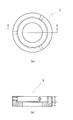
- FIG. 6 show preferable shapes of the ring-shaped balancing weight attached to the ultrasonic vibration imparting tool of the present invention, respectively. That is, in the ultrasonic vibration imparting tool, the central axis of the ultrasonic vibrator is slightly deviated due to a slight "shift" in the mounting position of the ring-shaped balancing weight that occurs during assembly or continuous use. However, the deviation of the central axis of such an ultrasonic vibration imparting tool may adversely affect the performance of the ultrasonic vibration imparting tool. In order to prevent or correct the deviation (bias) of the central axis of such an ultrasonic oscillator, it may be required to correct the deviation of the central axis.
- FIGS. 6A and 6B The plan view and the vertical front view of the shape of the ring-shaped balancing weight 5 provided with the female screw hole for adjusting the runout accuracy are shown in FIGS. 6A and 6B.
- FIG. 6 (a) it is desirable to form three or more female screw holes for adjusting the runout accuracy evenly along the plane of the ring-shaped balancing weight.
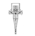
- FIG. 7 shows an image of an ultrasonic processing tool in which a tool is attached to the front mass of the ultrasonic vibration imparting tool of the present invention via a horn. That is, the ultrasonic processing tool shown in FIG. 7 has a configuration in which a tool is attached to the ultrasonic vibration imparting tool shown in FIGS. 2 to 5 via a horn, but even in this case, the vibration Although the number of nodes increases, ultrasonic vibration in a mode similar to the ultrasonic vibration shown in FIGS. 4 and 5 is generated.
Landscapes
- Physics & Mathematics (AREA)
- Engineering & Computer Science (AREA)
- Acoustics & Sound (AREA)
- Signal Processing (AREA)
- Apparatuses For Generation Of Mechanical Vibrations (AREA)
Abstract
L'invention concerne un outil d'ajout de vibrations ultrasonores comprenant une masse d'équilibrage annulaire ayant une partie filetée, au sommet d'une surface circonférentielle interne, dans laquelle la partie filetée d'un boîtier cylindrique est vissée. L'outil d'ajout de vibrations ultrasonores a une structure telle que, sous la partie filetée de cette masse d'équilibrage annulaire, se forme une partie inférieure de petit diamètre dont le diamètre intérieur est inférieur au diamètre intérieur de la partie filetée, et qu'un espace est formé entre la surface circonférentielle intérieure de la partie inférieure de petit diamètre et la face latérale d'une masse frontale en forme de colonne, le rayon (Hin) d'un cercle formé par la surface circonférentielle intérieure de la partie cylindrique du boîtier cylindrique étant plus grand que le rayon (Nin) d'un cercle formé par la surface circonférentielle intérieure de la partie inférieure de petit diamètre de la masse d'équilibrage annulaire, une différence de rayon (HN), i. e., Hin-Nin, étant de 0,01 fois à 1 fois le rayon (Fr) de la masse frontale en forme de colonne à un endroit en contact avec la surface inférieure d'une partie bombée en forme de disque (bride).
Priority Applications (1)
| Application Number | Priority Date | Filing Date | Title |
|---|---|---|---|
| JP2021513715A JPWO2020209362A1 (fr) | 2019-04-11 | 2020-04-10 |
Applications Claiming Priority (2)
| Application Number | Priority Date | Filing Date | Title |
|---|---|---|---|
| JP2019-087885 | 2019-04-11 | ||
| JP2019087885 | 2019-04-11 |
Publications (1)
| Publication Number | Publication Date |
|---|---|
| WO2020209362A1 true WO2020209362A1 (fr) | 2020-10-15 |
Family
ID=72751345
Family Applications (1)
| Application Number | Title | Priority Date | Filing Date |
|---|---|---|---|
| PCT/JP2020/016129 WO2020209362A1 (fr) | 2019-04-11 | 2020-04-10 | Outil d'ajout de vibrations ultrasonores |
Country Status (2)
| Country | Link |
|---|---|
| JP (1) | JPWO2020209362A1 (fr) |
| WO (1) | WO2020209362A1 (fr) |
Citations (6)
| Publication number | Priority date | Publication date | Assignee | Title |
|---|---|---|---|---|
| JPS63288601A (ja) * | 1987-05-20 | 1988-11-25 | Taga Electric Co Ltd | 超音波振動切削装置 |
| JP2001176932A (ja) * | 1999-12-20 | 2001-06-29 | Matsushita Electric Ind Co Ltd | 超音波振動体 |
| JP2010089007A (ja) * | 2008-10-08 | 2010-04-22 | Sonotec Co Ltd | 超音波加工装置 |
| WO2017065263A1 (fr) * | 2015-10-15 | 2017-04-20 | 有限会社Uwave | Procédé d'excitation pour transducteur d'ultrasons de langevin, procédé d'usinage aux ultrasons, et procédé de transmission à ultrasons |
| JP2018038992A (ja) * | 2016-09-05 | 2018-03-15 | 大西 一正 | 超音波加工用のランジュバン型超音波振動子とその支持方法 |
| JP2020028873A (ja) * | 2018-08-20 | 2020-02-27 | 有限会社Uwave | ランジュバン型超音波振動子とその支持方法 |
-
2020
- 2020-04-10 WO PCT/JP2020/016129 patent/WO2020209362A1/fr active Application Filing
- 2020-04-10 JP JP2021513715A patent/JPWO2020209362A1/ja active Pending
Patent Citations (6)
| Publication number | Priority date | Publication date | Assignee | Title |
|---|---|---|---|---|
| JPS63288601A (ja) * | 1987-05-20 | 1988-11-25 | Taga Electric Co Ltd | 超音波振動切削装置 |
| JP2001176932A (ja) * | 1999-12-20 | 2001-06-29 | Matsushita Electric Ind Co Ltd | 超音波振動体 |
| JP2010089007A (ja) * | 2008-10-08 | 2010-04-22 | Sonotec Co Ltd | 超音波加工装置 |
| WO2017065263A1 (fr) * | 2015-10-15 | 2017-04-20 | 有限会社Uwave | Procédé d'excitation pour transducteur d'ultrasons de langevin, procédé d'usinage aux ultrasons, et procédé de transmission à ultrasons |
| JP2018038992A (ja) * | 2016-09-05 | 2018-03-15 | 大西 一正 | 超音波加工用のランジュバン型超音波振動子とその支持方法 |
| JP2020028873A (ja) * | 2018-08-20 | 2020-02-27 | 有限会社Uwave | ランジュバン型超音波振動子とその支持方法 |
Also Published As
| Publication number | Publication date |
|---|---|
| JPWO2020209362A1 (fr) | 2020-10-15 |
Similar Documents
| Publication | Publication Date | Title |
|---|---|---|
| JP6863613B2 (ja) | 超音波振動付与具及び超音波加工装置 | |
| US4173725A (en) | Piezoelectrically driven ultrasonic transducer | |
| CN108136441B (zh) | 朗之万型超声波振子的振动激励方法以及超声波加工方法和超声波发送方法 | |
| JP4887492B2 (ja) | 非接触支持装置 | |
| JP6802290B2 (ja) | 超音波振動子及び超音波振動子を用いた超音波洗浄装置 | |
| JP6716082B2 (ja) | ランジュバン型超音波振動子の縦・ねじり振動の励起方法 | |
| WO2020209362A1 (fr) | Outil d'ajout de vibrations ultrasonores | |
| JP4827170B2 (ja) | ボルト締めランジュバン型振動子 | |
| WO2023195179A1 (fr) | Unité de rayonnement d'ondes ultrasonores | |
| US7466066B2 (en) | Longitudinally driven slotted cylinder transducer | |
| CN112188938B (zh) | 超声波振动赋予用具、行进波产生装置及超声波加工装置 | |
| JP2017170361A (ja) | ランジュバン型振動子および該ランジュバン型振動子を備えたアクティブソーナー | |
| JP2020028873A (ja) | ランジュバン型超音波振動子とその支持方法 | |
| WO2023181309A1 (fr) | Unité de vibrateur et machine à laver à vide à ultrasons | |
| KR102159856B1 (ko) | 큰 복사 면적을 가지는 초음파 장치 | |
| JP2006088135A (ja) | 超音波振動テーブル | |
| JP2020073274A (ja) | ランジュバン型超音波振動子の支持構造体、超音波加工装置及び超音波送信装置 | |
| JP2006150329A (ja) | 超音波振動テーブル | |
| JPS6118299A (ja) | ボルト締めランジュバン振動子 | |
| JP2020073275A (ja) | ランジュバン型超音波振動子の振動励起方法及び被加工材料の超音波加工方法 | |
| JP2006142468A (ja) | 超音波振動テーブル | |
| JPH09155289A (ja) | ボルト締めランジュバン型振動子 | |
| JP2005334984A (ja) | 振動テーブル | |
| JP2003018688A (ja) | 円筒型水中音源 | |
| JPH06197400A (ja) | 低周波水中送波器 |
Legal Events
| Date | Code | Title | Description |
|---|---|---|---|
| 121 | Ep: the epo has been informed by wipo that ep was designated in this application |
Ref document number: 20787782 Country of ref document: EP Kind code of ref document: A1 |
|
| ENP | Entry into the national phase |
Ref document number: 2021513715 Country of ref document: JP Kind code of ref document: A |
|
| NENP | Non-entry into the national phase |
Ref country code: DE |
|
| 122 | Ep: pct application non-entry in european phase |
Ref document number: 20787782 Country of ref document: EP Kind code of ref document: A1 |