WO2020209362A1 - Ultrasonic vibration adding tool - Google Patents
Ultrasonic vibration adding tool Download PDFInfo
- Publication number
- WO2020209362A1 WO2020209362A1 PCT/JP2020/016129 JP2020016129W WO2020209362A1 WO 2020209362 A1 WO2020209362 A1 WO 2020209362A1 JP 2020016129 W JP2020016129 W JP 2020016129W WO 2020209362 A1 WO2020209362 A1 WO 2020209362A1
- Authority
- WO
- WIPO (PCT)
- Prior art keywords
- ultrasonic vibration
- peripheral surface
- cylindrical
- vibration imparting
- ring
- Prior art date
Links
- 230000002093 peripheral effect Effects 0.000 claims description 32
- 229910000831 Steel Inorganic materials 0.000 claims description 2
- 239000000463 material Substances 0.000 claims description 2
- 230000000149 penetrating effect Effects 0.000 claims description 2
- 239000010959 steel Substances 0.000 claims description 2
- 238000012545 processing Methods 0.000 description 9
- 239000002184 metal Substances 0.000 description 4
- 230000005540 biological transmission Effects 0.000 description 2
- 238000011160 research Methods 0.000 description 2
- 241000251468 Actinopterygii Species 0.000 description 1
- 239000006061 abrasive grain Substances 0.000 description 1
- 230000002411 adverse Effects 0.000 description 1
- 238000000889 atomisation Methods 0.000 description 1
- 238000005452 bending Methods 0.000 description 1
- 238000004891 communication Methods 0.000 description 1
- 238000005520 cutting process Methods 0.000 description 1
- 238000011161 development Methods 0.000 description 1
- 238000010586 diagram Methods 0.000 description 1
- 239000006185 dispersion Substances 0.000 description 1
- 230000000694 effects Effects 0.000 description 1
- 238000004945 emulsification Methods 0.000 description 1
- 238000005516 engineering process Methods 0.000 description 1
- 239000007769 metal material Substances 0.000 description 1
- 238000000034 method Methods 0.000 description 1
- 238000004023 plastic welding Methods 0.000 description 1
- 230000010287 polarization Effects 0.000 description 1
- 238000005498 polishing Methods 0.000 description 1
- 238000002360 preparation method Methods 0.000 description 1
- 239000011343 solid material Substances 0.000 description 1
- 238000004506 ultrasonic cleaning Methods 0.000 description 1
Images


Classifications
-
- H—ELECTRICITY
- H04—ELECTRIC COMMUNICATION TECHNIQUE
- H04R—LOUDSPEAKERS, MICROPHONES, GRAMOPHONE PICK-UPS OR LIKE ACOUSTIC ELECTROMECHANICAL TRANSDUCERS; DEAF-AID SETS; PUBLIC ADDRESS SYSTEMS
- H04R17/00—Piezoelectric transducers; Electrostrictive transducers
- H04R17/10—Resonant transducers, i.e. adapted to produce maximum output at a predetermined frequency
Definitions
- the present invention relates to an ultrasonic vibration imparting tool using a Langevin type ultrasonic oscillator. Background technology
- ultrasonic vibrators using a piezoelectric element as an ultrasonic wave generator are known and are used as ultrasonic vibration imparting tools.
- a Langevin type ultrasonic oscillator composed of a pair of metal blocks and a polarized piezoelectric element fixed between these metal blocks is known. ..
- the bolted Langevin type ultrasonic vibrator which has a structure in which polarized piezoelectric elements are connected by bolts between a pair of metal blocks and tightened and fixed at high pressure, can generate high-energy ultrasonic vibrations.
- ultrasonic processing which is attached to tools for polishing, cutting, plastic working, abrasive grain processing, etc. of various solid materials
- ultrasonic cleaning, metal bonding, plastic welding, and ultrasonic waves are performed by transmitting the ultrasonic vibration generated by the ultrasonic vibrator via a vibrating plate or various vibrating means.
- Applications for ultrasonic processing such as atomization, emulsification / dispersion, and also for underwater acoustic devices (sonar) such as fish finder, ultrasonic flaw detectors, medical echo diagnostic devices, and communication application devices such as flow meters. It has been considered and is actually in use.
- Patent Document 1 is written on August 16, 2018, which is earlier than the filing date (April 11, 2019) of the Japanese patent application (JP2019-087885) in which the priority based on the Paris Convention is claimed in this patent application.
- the published PCT / JP2018 / 00428 international publication WO 2018/147445 A1 is shown in Patent Document 1 as FIG. 1 (prior art: PRIOR ART) in the attached drawings of the present application (FIG. 4).
- a cylindrical housing with a contact surface at the bottom or bottom of the inner peripheral surface and a threaded portion at the bottom of the outer peripheral surface; a disk with a contact surface that is fitted to the contact surface of the cylindrical housing.
- the invention of an ultrasonic vibration imparting tool including a ring-shaped balancing weight (ring-shaped vibration weight) having a screw portion on which the screw portion of the cylindrical housing is screwed is disclosed. Has been done.
- Patent Document 1 as a preferable configuration of the ring-shaped balancing weight, a lower small diameter portion having an inner diameter smaller than the inner diameter of the threaded portion is formed on the lower side of the threaded portion, and the lower small diameter portion thereof is formed.
- a configuration in which a gap is formed between the inner peripheral surface of the portion and the side surface of the cylindrical tool attachment (which also serves as the front mass) is also disclosed. Then, in FIGS. 4 and 8 and 9, the ultrasonic vibration imparting tool is supported (or held) by a supporting (or holding) member provided around or above the cylindrical housing. It is shown.
- Patent Document 1 states that when ultrasonic processing is performed using an ultrasonic processing apparatus incorporating the ultrasonic vibration imparting tool of the invention disclosed therein, the ultrasonic vibration energy generated by the ultrasonic vibration imparting tool is supported. Leakage to the member is significantly reduced, and therefore, the ultrasonic vibration generated by the Langevin type ultrasonic vibrator can be transmitted to the tool attached to the ultrasonic vibration imparting tool with high efficiency and high stability. There is a statement to the effect that it will be possible.
- Patent Document 1 WO 2018/147445 A1 (International Publication of PCT / JP2018 / 00428)
- Patent Document 1 The inventor of the present invention is the inventor of the invention disclosed in Patent Document 1, but in order to further improve the ultrasonic vibration imparting efficiency of the ultrasonic vibration imparting tool disclosed in Patent Document 1, Patent Document Improvement of the ultrasonic vibration imparting tool according to No. 1 (in particular, ultrasonic vibration imparting capable of transmitting ultrasonic vibration generated by a Langevin type ultrasonic vibrator to a tool or the like mounted on the front mass with higher efficiency. Since then, I have continued research aimed at (development of tools). Means to solve problems
- the inventor of the present invention considers the ultrasonic vibration imparting tool having the basic configuration described in Patent Document 1 as the ultrasonic vibration imparting tool when the configuration satisfies the conditions described below.
- the present invention has been reached by finding that the function of the above is further improved and the ultrasonic vibration imparting tool is more advantageous for industrial use.
- the ultrasonic vibration imparting tool provided by the present invention is an ultrasonic vibration imparting tool having the following configuration.
- Langeban type ultrasonic transducer and an ultrasonic vibration imparting tool including a ring-shaped balancing weight having a threaded portion on the upper part of the inner peripheral surface into which the threaded portion of the cylindrical housing is screwed, of the ring-shaped balancing weight.
- a small diameter portion (lower small diameter portion) having an inner diameter smaller than the inner diameter of the screw portion is formed on the lower side of the threaded portion, and between the inner peripheral surface of the lower small diameter portion and the side surface of the cylindrical front mass.
- the radius (Hin) of the circle formed by the inner peripheral surface of the cylindrical part of the cylindrical housing is the radius of the circle formed by the inner peripheral surface of the lower small diameter part of the ring-shaped equilibrium weight (Hin).
- the cylindrical housing is made of a metal material (particularly a steel material).
- the ultrasonic vibration imparting tool is supported (or held) by a supporting (or holding) member provided around or above the cylindrical housing.
- Three or more through holes penetrating from the outer peripheral surface to the inner peripheral surface are formed in the threaded portion (upper large diameter portion) of the ring-shaped balancing weight.
- a tool mounting opening is formed below the front mass.
- the ultrasonic vibration imparting tool of the present invention When the ultrasonic vibration imparting tool of the present invention is incorporated into an ultrasonic processing device or an ultrasonic transmission device via a support to generate ultrasonic vibration, the ultrasonic vibration generated by the Langevin type ultrasonic vibrator is supported. There is little leakage to the body, and it can be reliably and highly efficiently transmitted to the tools and vibrating bodies attached to the front mass. Therefore, it is possible to reduce the electric power energy required to drive the ultrasonic vibration device.
- FIG. 1 It is a front sectional view (vibration mode is also shown) which shows the structural example of the ultrasonic vibration imparting tool (the ultrasonic vibration imparting tool disclosed in Patent Document 1) belonging to the prior art (PRIOR ART). It is a top view of the example of the ultrasonic vibration imparting tool of this invention, and shows the state supported by the support member. It is a front sectional view of the ultrasonic vibration imparting tool (supported by a support member) shown in FIG. Vibration of the Langevin type ultrasonic oscillator generated when electric energy is applied to the ultrasonic vibration imparting device of the present invention shown in FIGS. 2 and 3, vibration of the flange portion of the front mass, and ring-shaped balanced weight.
- FIG. 4 shows a state in which the Langevin type ultrasonic oscillator is in a lowered position due to vibration.
- the vibration of the Langevin type ultrasonic oscillator constituting the ultrasonic vibration imparting tool of the present invention shown in FIG. 4 the vibration of the disk-shaped bulge (flange) of the columnar front mass, and the vibration of the ring-shaped equilibrium weight, respectively.
- FIG. 4 shows by a method different from FIG.
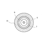
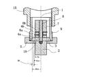
- FIGS. 2 and 3 are views showing a typical configuration example of the ultrasonic vibration imparting tool of the present invention, in which the ultrasonic vibration imparting tool supports (or holds) the ultrasonic vibration imparting tool provided around or above the cylindrical housing. Indicates a state of being supported (or held) by a member.
- the ultrasonic vibration imparting tool of the present invention shown in FIGS. 2 and 3 has a configuration similar to that of the ultrasonic vibration imparting tool disclosed in Patent Document 1.
- the ultrasonic vibration imparting tool 1 shown in FIGS. 2 and 3 is provided with a contact surface (contact surface with the end surface of the flange 3 formed on the upper portion of the front mass 2) at the lower portion or the bottom portion of the inner peripheral surface.
- the polarization-treated piezoelectric elements 4a and 4b are sandwiched between the cylindrical front mass 2 on which the is mounted and the cylindrical rear mass 7 arranged above the front mass 2 by the electrodes 6a and 6b, and the bolts 8 are used.
- a flange van type ultrasonic transducer 1 having a fixed configuration; and an ultrasonic vibration imparting tool including a ring-shaped balancing weight 5 having a threaded portion on the lower outer peripheral surface of the cylindrical housing 9 on the upper inner peripheral surface, which is a ring.
- a lower small diameter portion having an inner diameter smaller than the inner diameter of the threaded portion is formed on the lower side of the threaded portion of the balanced weight 5, and the inner peripheral surface of the lower small diameter portion and the side surface of the cylindrical front mass 2 are formed.
- a circle having a structure in which a gap is formed between them, and the radius (Hin) of the circle formed by the inner peripheral surface of the cylindrical portion of the cylindrical housing 9 is a ring-shaped equilibrium weight 5 formed by the inner peripheral surface of the lower small diameter portion.
- the radius (Fr) of the cylindrical front mass 2 at the position where (HN), which is larger than the radius (Nin) of the flange 3 and is the difference from the radius (that is, Hin-Nin), is in contact with the lower surface of the flange 3 is 0. It is an ultrasonic vibration imparting tool 1 which is 0.01 times or more and 1 times or less. Note that FIGS. 2 and 3 show a state in which the ultrasonic vibration imparting tool 1 is supported (or held) by a supporting (or holding) member 15 provided around or above the cylindrical housing 9.
- the ultrasonic vibration imparting tool of the present invention is an ultrasonic vibration imparting tool described in Patent Document 1 and having a basic configuration similar to that of the illustrated ultrasonic vibration imparting tool, but the cylindrical portion of the cylindrical housing.
- the radius (Hin) of the circle formed by the inner peripheral surface is larger than the radius (Nin) of the circle formed by the inner peripheral surface of the lower small diameter portion of the ring-shaped equilibrium weight, and the difference from the radius (that is, Hin-Nin).
- the ultrasonic vibration imparting tool of the present invention has a basic configuration similar to that of the ultrasonic vibration imparting tool described in Patent Document 1 and shown, but within the cylindrical portion of the cylindrical housing.
- the radius (Hin) of the circle formed by the peripheral surface is larger than the radius (Nin) of the circle formed by the inner peripheral surface of the lower small diameter portion of the ring-shaped equilibrium weight, and is the difference (Hin-Nin) from the radius.
- the difference is that (HN) is 0.01 times or more and 1 time or less of the radius (Fr) of the cylindrical front mass at the position in contact with the lower surface of the disk-shaped bulge (flange).
- the lower small diameter portion of the ring-shaped balancing weight that contacts the lower surface of the disk-shaped bulging portion (flange) is compared with the ultrasonic vibration imparting tool described in Patent Document 1.
- the contact area of the upper surface becomes large. Therefore, the ultrasonic vibration generated by the Langevin type ultrasonic oscillator and transmitted to the flange can be transmitted to the ring-shaped balanced weight with higher efficiency.
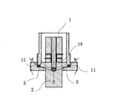
- FIGS. 4 and 5 are diagrams diagrammatically showing the transmission of the ultrasonic vibration transmitted to the flange to the ring-shaped balanced weight with high efficiency, respectively. That is, the vertical vibration (butterfly vibration) of the outer peripheral end of the ring-shaped balancing weight becomes large. Then, due to the vertical vibration (butterfly vibration) increased at the outer peripheral end portion, the bending vibration of the flange of the front mass in the vertical direction increases from the screw surface of the upper large diameter portion through the lower part of the housing, and as a result, The ultrasonic vibration in the vertical direction of the front mass increases. That is, the ultrasonic vibration in the vertical direction generated by the Langevin type ultrasonic vibrator is amplified and transmitted to the tool or the vibrating tool equipped with the front mass.
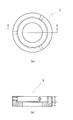
- FIG. 6 show preferable shapes of the ring-shaped balancing weight attached to the ultrasonic vibration imparting tool of the present invention, respectively. That is, in the ultrasonic vibration imparting tool, the central axis of the ultrasonic vibrator is slightly deviated due to a slight "shift" in the mounting position of the ring-shaped balancing weight that occurs during assembly or continuous use. However, the deviation of the central axis of such an ultrasonic vibration imparting tool may adversely affect the performance of the ultrasonic vibration imparting tool. In order to prevent or correct the deviation (bias) of the central axis of such an ultrasonic oscillator, it may be required to correct the deviation of the central axis.
- FIGS. 6A and 6B The plan view and the vertical front view of the shape of the ring-shaped balancing weight 5 provided with the female screw hole for adjusting the runout accuracy are shown in FIGS. 6A and 6B.
- FIG. 6 (a) it is desirable to form three or more female screw holes for adjusting the runout accuracy evenly along the plane of the ring-shaped balancing weight.
- FIG. 7 shows an image of an ultrasonic processing tool in which a tool is attached to the front mass of the ultrasonic vibration imparting tool of the present invention via a horn. That is, the ultrasonic processing tool shown in FIG. 7 has a configuration in which a tool is attached to the ultrasonic vibration imparting tool shown in FIGS. 2 to 5 via a horn, but even in this case, the vibration Although the number of nodes increases, ultrasonic vibration in a mode similar to the ultrasonic vibration shown in FIGS. 4 and 5 is generated.
Abstract
An ultrasonic vibration adding tool including a ring-shaped balance weight having a threaded part, at the top of an inner circumferential surface, which the threaded part of a cylindrical housing is screwed into. The ultrasonic vibration adding tool has such a structure that, below the threaded part of this ring-shaped balance weight is formed a lower small diameter part the inner diameter of which is smaller than the inner diameter of the threaded part, and a space is formed between the inner circumferential surface of the lower small diameter part and the side face of a columnar front mass, the radius (Hin) of a circle formed by the inner circumferential surface of cylindrical part of the cylindrical housing being larger than the radius (Nin) of a circle formed by the inner circumferential surface of the lower small diameter part of the ring-shaped balance weight, a difference in radius (HN), i.e., Hin-Nin, being 0.01-fold to 1-fold of the radius (Fr) of the columnar front mass at a position in contact with the lower surface of a disc-shaped bulge part (flange).
Description
本発明は、ランジュバン型超音波振動子を用いる超音波振動付与具に関する。
背景技術 The present invention relates to an ultrasonic vibration imparting tool using a Langevin type ultrasonic oscillator.
Background technology
背景技術 The present invention relates to an ultrasonic vibration imparting tool using a Langevin type ultrasonic oscillator.
Background technology
圧電素子を超音波発生源とする超音波振動子は各種の構成のものが知られていて、超音波振動付与具として利用されている。そして、超音波振動子の代表的な構成としては、一対の金属ブロックとこれらの金属ブロックの間に固定された分極処理済の圧電素子から構成されたランジュバン型超音波振動子が知られている。なかでも、分極処理済の圧電素子を一対の金属ブロックの間でボルトで接続し、高圧で締め付け固定した構造のボルト締めランジュバン型超音波振動子は、高エネルギーの超音波振動の発生が可能なことから、各種固体材料の研磨加工、切削加工、塑性加工、砥粒加工などを行うための工具に付設して用いる超音波加工処理での利用が検討され、実際に使用されている。さらに、各種の超音波振動子については、その超音波振動子にて発生する超音波振動を振動板や各種振動手段を介して送信することによる、超音波洗浄、金属接合、プラスチック溶着、超音波霧化、乳化・分散などの超音波処理の用途、そして魚群探知機などの水中音響器(ソナー)、超音波探傷器、医療用エコー診断装置、流量計などの通信的応用機器への利用も検討され、実際に使用されている。
Various types of ultrasonic vibrators using a piezoelectric element as an ultrasonic wave generator are known and are used as ultrasonic vibration imparting tools. As a typical configuration of the ultrasonic oscillator, a Langevin type ultrasonic oscillator composed of a pair of metal blocks and a polarized piezoelectric element fixed between these metal blocks is known. .. Among them, the bolted Langevin type ultrasonic vibrator, which has a structure in which polarized piezoelectric elements are connected by bolts between a pair of metal blocks and tightened and fixed at high pressure, can generate high-energy ultrasonic vibrations. Therefore, its use in ultrasonic processing, which is attached to tools for polishing, cutting, plastic working, abrasive grain processing, etc. of various solid materials, has been studied and is actually used. Furthermore, for various ultrasonic vibrators, ultrasonic cleaning, metal bonding, plastic welding, and ultrasonic waves are performed by transmitting the ultrasonic vibration generated by the ultrasonic vibrator via a vibrating plate or various vibrating means. Applications for ultrasonic processing such as atomization, emulsification / dispersion, and also for underwater acoustic devices (sonar) such as fish finder, ultrasonic flaw detectors, medical echo diagnostic devices, and communication application devices such as flow meters. It has been considered and is actually in use.
特許文献1は、本特許出願でパリ条約に基づく優先権が主張されている日本特許出願(JP2019-087885)の出願日(2019年4月11日)より以前である2018年8月16日に公開されたPCT/JP2018/004728の国際公開公報WO 2018/147445 A1であるが、この特許文献1には、本願の添付図面に図1(先行技術:PRIOR ART)として示した図面(図4)が添付され、そして、接触面を内周面下部もしくは底部に備え、そして外周面下部にねじ部を備えた円筒状ハウジング;この円筒状ハウジングの上記接触面に嵌め合わされる接触面を備えた円盤状膨出部(フランジ)を上部に有する円筒状工具取付具を含むフロントマスと、そのフロントマスの上方に配置したリアマスとの間に分極処理済の圧電素子を挟んだ状態でボルト締めした構成のランジュバン型超音波振動子;そして、上記円筒状ハウジングのねじ部がねじ込まれるねじ部を内周面上部に有するリング状釣り合い重り(リング状振動重り)を含む超音波振動付与具の発明が開示されている。
Patent Document 1 is written on August 16, 2018, which is earlier than the filing date (April 11, 2019) of the Japanese patent application (JP2019-087885) in which the priority based on the Paris Convention is claimed in this patent application. The published PCT / JP2018 / 00428 international publication WO 2018/147445 A1 is shown in Patent Document 1 as FIG. 1 (prior art: PRIOR ART) in the attached drawings of the present application (FIG. 4). A cylindrical housing with a contact surface at the bottom or bottom of the inner peripheral surface and a threaded portion at the bottom of the outer peripheral surface; a disk with a contact surface that is fitted to the contact surface of the cylindrical housing. A configuration in which a polarized piezoelectric element is sandwiched between a front mass including a cylindrical tool fixture having a bulging portion (flange) at the top and a rear mass arranged above the front mass, and bolted. The invention of an ultrasonic vibration imparting tool including a ring-shaped balancing weight (ring-shaped vibration weight) having a screw portion on which the screw portion of the cylindrical housing is screwed is disclosed. Has been done.
特許文献1には、さらに、上記のリング状釣り合い重りの好ましい構成として、そのねじ部の下側に内径が該ねじ部の内径よりも小さい下側小径部が形成されていて、その下側小径部の内周面と円筒状工具取り付け具(フロントマスを兼ねる)の側面との間に空隙が形成された構成も開示されている。そして、上記の図4、そして図8と図9には、超音波振動付与具が、円筒状ハウジングの周囲あるいは上部に設けられた支持(或いは保持)部材によって支持(或いは保持)されている構成が示されている。
Further, in Patent Document 1, as a preferable configuration of the ring-shaped balancing weight, a lower small diameter portion having an inner diameter smaller than the inner diameter of the threaded portion is formed on the lower side of the threaded portion, and the lower small diameter portion thereof is formed. A configuration in which a gap is formed between the inner peripheral surface of the portion and the side surface of the cylindrical tool attachment (which also serves as the front mass) is also disclosed. Then, in FIGS. 4 and 8 and 9, the ultrasonic vibration imparting tool is supported (or held) by a supporting (or holding) member provided around or above the cylindrical housing. It is shown.
特許文献1には、そこに開示された発明の超音波振動付与具を組み込んだ超音波加工装置を用いて超音波加工を行うと、超音波振動付与具で発生した超音波振動エネルギーの上記支持部材への漏出が顕著に低減し、このため、ランジュバン型超音波振動子で発生した超音波振動を、超音波振動付与具に取り付けられた工具に、高い効率かつ高い安定性を以て伝達することが可能となるとの趣旨の記載が見られる。
Patent Document 1 states that when ultrasonic processing is performed using an ultrasonic processing apparatus incorporating the ultrasonic vibration imparting tool of the invention disclosed therein, the ultrasonic vibration energy generated by the ultrasonic vibration imparting tool is supported. Leakage to the member is significantly reduced, and therefore, the ultrasonic vibration generated by the Langevin type ultrasonic vibrator can be transmitted to the tool attached to the ultrasonic vibration imparting tool with high efficiency and high stability. There is a statement to the effect that it will be possible.
特許文献1:WO 2018/147445 A1(PCT/JP2018/004728の国際公開公報)
Patent Document 1: WO 2018/147445 A1 (International Publication of PCT / JP2018 / 00428)
本発明の発明者は、上記特許文献1に開示された発明の発明者であるが、特許文献1に開示された超音波振動付与具の超音波振動付与効率をさらに向上させるために、特許文献1に記載の超音波振動付与具の改良(特に、ランジュバン型超音波振動子で発生する超音波振動を、フロントマスに装着された工具等にさらに高い効率で伝達することができる超音波振動付与具の開発)を目的とした研究をその後も続けてきた。
課題を解決するための手段 The inventor of the present invention is the inventor of the invention disclosed inPatent Document 1, but in order to further improve the ultrasonic vibration imparting efficiency of the ultrasonic vibration imparting tool disclosed in Patent Document 1, Patent Document Improvement of the ultrasonic vibration imparting tool according to No. 1 (in particular, ultrasonic vibration imparting capable of transmitting ultrasonic vibration generated by a Langevin type ultrasonic vibrator to a tool or the like mounted on the front mass with higher efficiency. Since then, I have continued research aimed at (development of tools).
Means to solve problems
課題を解決するための手段 The inventor of the present invention is the inventor of the invention disclosed in
Means to solve problems
上記の研究の結果、本発明の発明者は、特許文献1に記載の基本構成を持つ超音波振動付与具は、以下に記載する条件を満たす構成とした場合に、その超音波振動付与具としての機能がさらに向上して、工業的使用にさらに有利な超音波振動付与具となることを見出し、本発明に到達した。
As a result of the above research, the inventor of the present invention considers the ultrasonic vibration imparting tool having the basic configuration described in Patent Document 1 as the ultrasonic vibration imparting tool when the configuration satisfies the conditions described below. The present invention has been reached by finding that the function of the above is further improved and the ultrasonic vibration imparting tool is more advantageous for industrial use.
本発明が提供する超音波振動付与具は、下記の構成を持つ超音波振動付与具である。
接触面を内周面下部もしくは底部に備え、そして外周面下部にねじ部を備えた円筒状ハウジング;この円筒状ハウジングの上記接触面に嵌め合わされる接触面を備えた円盤状膨出部(フランジ)を上部に有し、下部に工具が装着される円柱状フロントマスと、そのフロントマスの上方に配置した円柱状リアマスとの間に分極処理済の圧電素子を挟んだ状態でボルト締めした構成のランジュバン型超音波振動子;そして、上記円筒状ハウジングのねじ部がねじ込まれるねじ部を内周面上部に有するリング状釣り合い重りを含む超音波振動付与具であって、このリング状釣り合い重りのねじ部の下側には内径が該ねじ部の内径よりも小さい小径部(下側小径部)が形成されていて、その下側小径部の内周面と円柱状フロントマスの側面との間に空隙が形成された構成を持ち、円筒状ハウジングの円筒部の内周面が形成する円の半径(Hin)がリング状釣り合い重りの下側小径部の内周面が形成する円の半径(Nin)よりも大きく、その半径との差(即ち、Hin-Nin)である(HN)が、上記円盤状膨出部(フランジ)の下側表面に接する位置における円柱状フロントマスの半径(Fr)の0.01倍以上、1倍以下である超音波振動付与具。 The ultrasonic vibration imparting tool provided by the present invention is an ultrasonic vibration imparting tool having the following configuration.
A cylindrical housing with a contact surface at the bottom or bottom of the inner peripheral surface and a thread at the bottom of the outer peripheral surface; a disc-shaped bulge (flange) with a contact surface fitted to the contact surface of the cylindrical housing. ) Is held at the top, and a cylindrical front mass on which a tool is mounted at the bottom and a cylindrical rear mass placed above the front mass are bolted together with a polarized piezoelectric element sandwiched between them. Langeban type ultrasonic transducer; and an ultrasonic vibration imparting tool including a ring-shaped balancing weight having a threaded portion on the upper part of the inner peripheral surface into which the threaded portion of the cylindrical housing is screwed, of the ring-shaped balancing weight. A small diameter portion (lower small diameter portion) having an inner diameter smaller than the inner diameter of the screw portion is formed on the lower side of the threaded portion, and between the inner peripheral surface of the lower small diameter portion and the side surface of the cylindrical front mass. The radius (Hin) of the circle formed by the inner peripheral surface of the cylindrical part of the cylindrical housing is the radius of the circle formed by the inner peripheral surface of the lower small diameter part of the ring-shaped equilibrium weight (Hin). The radius (Fr) of the cylindrical front mass at the position where (HN), which is larger than Nin) and is the difference from the radius (that is, Hin-Nin), is in contact with the lower surface of the disk-shaped bulge (flange). ) Is 0.01 times or more and 1 time or less.
本発明の超音波振動付与具の好ましい態様を以下に記載する。
(1)円筒状ハウジングが金属材料(特に、鋼材)から形成されている。
(2)超音波振動付与具が、円筒状ハウジングの周囲あるいは上部に設けられた支持(或いは保持)部材によって支持(或いは保持)されている。
(3)リング状釣り合い重りのネジ部(上側大径部)に、その外周面から内周面に貫通する3個もしくはそれ以上の貫通孔が形成されている。
(4)フロントマスの下方に工具装着用開口部が形成されている。 A preferred embodiment of the ultrasonic vibration imparting tool of the present invention is described below.
(1) The cylindrical housing is made of a metal material (particularly a steel material).
(2) The ultrasonic vibration imparting tool is supported (or held) by a supporting (or holding) member provided around or above the cylindrical housing.
(3) Three or more through holes penetrating from the outer peripheral surface to the inner peripheral surface are formed in the threaded portion (upper large diameter portion) of the ring-shaped balancing weight.
(4) A tool mounting opening is formed below the front mass.
本発明の超音波振動付与具を、支持体を介して超音波加工装置や超音波伝送装置に組み込んで超音波振動を発生させただ場合、ランジュバン型超音波振動子で発生する超音波振動の支持体への漏出が少なく、フロントマスに装着された工具や振動体に確実にかつ高い効率で伝達することができる。このため、超音波振動装置の駆動に必要な電力エネルギーの低減が可能となる。
When the ultrasonic vibration imparting tool of the present invention is incorporated into an ultrasonic processing device or an ultrasonic transmission device via a support to generate ultrasonic vibration, the ultrasonic vibration generated by the Langevin type ultrasonic vibrator is supported. There is little leakage to the body, and it can be reliably and highly efficiently transmitted to the tools and vibrating bodies attached to the front mass. Therefore, it is possible to reduce the electric power energy required to drive the ultrasonic vibration device.
図2乃至図7を参照して、本発明の超音波振動付与装置の詳しい説明を記載する。
A detailed description of the ultrasonic vibration imparting device of the present invention will be described with reference to FIGS. 2 to 7.
図2と図3は、本発明の超音波振動付与具の代表的な構成例を示す図であり、超音波振動付与具が、円筒状ハウジングの周囲あるいは上部に設けられた支持(或いは保持)部材によって支持(或いは保持)されている状態を示す。
2 and 3 are views showing a typical configuration example of the ultrasonic vibration imparting tool of the present invention, in which the ultrasonic vibration imparting tool supports (or holds) the ultrasonic vibration imparting tool provided around or above the cylindrical housing. Indicates a state of being supported (or held) by a member.
図2と図3に示した本発明の超音波振動付与具は、特許文献1に開示した超音波振動付与具と類似の構成を持つ。
The ultrasonic vibration imparting tool of the present invention shown in FIGS. 2 and 3 has a configuration similar to that of the ultrasonic vibration imparting tool disclosed in Patent Document 1.
すなわち、図2と図3に示した超音波振動付与具1は、接触面(フロントマス2の上部に形成されたフランジ3の端面との接触面)を内周面下部もしくは底部に備え、そして外周面下部にねじ部を備えた円筒状ハウジング9;円筒状ハウジング9の上記接触面に嵌め合わされる接触面を備えたフランジ3(円盤状膨出部)を上部18に有し、下部に工具が装着される円柱状フロントマス2と、フロントマス2の上方に配置された円柱状リアマス7との間に分極処理済の圧電素子4a、4bを電極6a、6bで挟んだ状態でボルト8により固定された構成のランジュバン型超音波振動子1;そして、円筒状ハウジング9の外周面下部のねじ部を内周面上部に有するリング状釣り合い重り5を含む超音波振動付与具であって、リング状釣り合い重り5の上記ねじ部の下側に、内径がねじ部の内径よりも小さい下側小径部が形成されていて、下側小径部の内周面と円柱状フロントマス2の側面との間に空隙が形成された構成を持ち、円筒状ハウジング9の円筒部の内周面が形成する円の半径(Hin)がリング状釣り合い重り5の下側小径部の内周面が形成する円の半径(Nin)よりも大きく、その半径との差(即ち、Hin-Nin)である(HN)が、フランジ3の下側表面に接する位置における円柱状フロントマス2の半径(Fr)の0.01倍以上、1倍以下である超音波振動付与具1である。なお、図2と図3では、超音波振動付与具1が、円筒状ハウジング9の周囲あるいは上部に設けられた支持(或いは保持)部材15によって支持(或いは保持)されている状態を示す。
That is, the ultrasonic vibration imparting tool 1 shown in FIGS. 2 and 3 is provided with a contact surface (contact surface with the end surface of the flange 3 formed on the upper portion of the front mass 2) at the lower portion or the bottom portion of the inner peripheral surface. Cylindrical housing 9 with a threaded portion at the bottom of the outer peripheral surface; a flange 3 (disk-shaped bulge) with a contact surface fitted to the contact surface of the cylindrical housing 9 at the top 18 and a tool at the bottom. The polarization-treated piezoelectric elements 4a and 4b are sandwiched between the cylindrical front mass 2 on which the is mounted and the cylindrical rear mass 7 arranged above the front mass 2 by the electrodes 6a and 6b, and the bolts 8 are used. A flange van type ultrasonic transducer 1 having a fixed configuration; and an ultrasonic vibration imparting tool including a ring-shaped balancing weight 5 having a threaded portion on the lower outer peripheral surface of the cylindrical housing 9 on the upper inner peripheral surface, which is a ring. A lower small diameter portion having an inner diameter smaller than the inner diameter of the threaded portion is formed on the lower side of the threaded portion of the balanced weight 5, and the inner peripheral surface of the lower small diameter portion and the side surface of the cylindrical front mass 2 are formed. A circle having a structure in which a gap is formed between them, and the radius (Hin) of the circle formed by the inner peripheral surface of the cylindrical portion of the cylindrical housing 9 is a ring-shaped equilibrium weight 5 formed by the inner peripheral surface of the lower small diameter portion. The radius (Fr) of the cylindrical front mass 2 at the position where (HN), which is larger than the radius (Nin) of the flange 3 and is the difference from the radius (that is, Hin-Nin), is in contact with the lower surface of the flange 3 is 0. It is an ultrasonic vibration imparting tool 1 which is 0.01 times or more and 1 times or less. Note that FIGS. 2 and 3 show a state in which the ultrasonic vibration imparting tool 1 is supported (or held) by a supporting (or holding) member 15 provided around or above the cylindrical housing 9.
すなわち、本発明の超音波振動付与具は、特許文献1に記載され、図示された超音波振動付与具と類似の基本構成を持つ超音波振動付与具であるが、円筒状ハウジングの円筒部の内周面が形成する円の半径(Hin)がリング状釣り合い重りの下側小径部の内周面が形成する円の半径(Nin)よりも大きく、その半径との差(即ち、Hin-Nin)である(HN)が、円盤状膨出部(フランジ)の下側表面に接する位置における円柱状フロントマスの半径(Fr)の0.01倍以上、1倍以下である点において相違する。
That is, the ultrasonic vibration imparting tool of the present invention is an ultrasonic vibration imparting tool described in Patent Document 1 and having a basic configuration similar to that of the illustrated ultrasonic vibration imparting tool, but the cylindrical portion of the cylindrical housing. The radius (Hin) of the circle formed by the inner peripheral surface is larger than the radius (Nin) of the circle formed by the inner peripheral surface of the lower small diameter portion of the ring-shaped equilibrium weight, and the difference from the radius (that is, Hin-Nin). ) Is 0.01 times or more and 1 time or less of the radius (Fr) of the columnar front mass at the position in contact with the lower surface of the disk-shaped bulge (flange).
これまでに説明したように、本発明の超音波振動付与具は、特許文献1に記載され、図示された超音波振動付与具と類似の基本構成を持つが、円筒状ハウジングの円筒部の内周面が形成する円の半径(Hin)がリング状釣り合い重りの下側小径部の内周面が形成する円の半径(Nin)よりも大きく、その半径との差(Hin-Nin)である(HN)が、円盤状膨出部(フランジ)の下側表面に接する位置における円柱状フロントマスの半径(Fr)の0.01倍以上、1倍以下であることが異なる。
そして、このような構成の相違により、特許文献1に記載の超音波振動付与具に比べて、円盤状膨出部(フランジ)の下側表面に接触するリング状釣り合い重りの下側小径部の上側表面の接触面積が大きくなる。このため、ランジュバン型超音波振動子で発生し、上記フランジに伝達された超音波振動は、より高い効率でリング状釣り合い重りに伝えられるようになる。 As described above, the ultrasonic vibration imparting tool of the present invention has a basic configuration similar to that of the ultrasonic vibration imparting tool described inPatent Document 1 and shown, but within the cylindrical portion of the cylindrical housing. The radius (Hin) of the circle formed by the peripheral surface is larger than the radius (Nin) of the circle formed by the inner peripheral surface of the lower small diameter portion of the ring-shaped equilibrium weight, and is the difference (Hin-Nin) from the radius. The difference is that (HN) is 0.01 times or more and 1 time or less of the radius (Fr) of the cylindrical front mass at the position in contact with the lower surface of the disk-shaped bulge (flange).
Due to such a difference in configuration, the lower small diameter portion of the ring-shaped balancing weight that contacts the lower surface of the disk-shaped bulging portion (flange) is compared with the ultrasonic vibration imparting tool described inPatent Document 1. The contact area of the upper surface becomes large. Therefore, the ultrasonic vibration generated by the Langevin type ultrasonic oscillator and transmitted to the flange can be transmitted to the ring-shaped balanced weight with higher efficiency.
そして、このような構成の相違により、特許文献1に記載の超音波振動付与具に比べて、円盤状膨出部(フランジ)の下側表面に接触するリング状釣り合い重りの下側小径部の上側表面の接触面積が大きくなる。このため、ランジュバン型超音波振動子で発生し、上記フランジに伝達された超音波振動は、より高い効率でリング状釣り合い重りに伝えられるようになる。 As described above, the ultrasonic vibration imparting tool of the present invention has a basic configuration similar to that of the ultrasonic vibration imparting tool described in
Due to such a difference in configuration, the lower small diameter portion of the ring-shaped balancing weight that contacts the lower surface of the disk-shaped bulging portion (flange) is compared with the ultrasonic vibration imparting tool described in
図4と図5は、それぞれ、上記したフランジに伝達された超音波振動の高い効率でのリング状釣り合い重りへの伝達を図式的に示した図である。
すなわち、リング状釣り合い重りの外周端部の上下振動(バタフライ振動)は大きくなる。そして、この外周端部で大きくなった上下振動(バタフライ振動)により、上側大径部のネジ面よりハウジングの下部を介してフロントマスのフランジの上下方向での撓み振動が大きくなり、その結果、フロントマスの上下方向の超音波振動が大きくなる。すなわち、ランジュバン型超音波振動子で発生した上下方向の超音波振動は増幅されてフロントマスの装着された工具や振動具に伝達されることになる。 4 and 5 are diagrams diagrammatically showing the transmission of the ultrasonic vibration transmitted to the flange to the ring-shaped balanced weight with high efficiency, respectively.
That is, the vertical vibration (butterfly vibration) of the outer peripheral end of the ring-shaped balancing weight becomes large. Then, due to the vertical vibration (butterfly vibration) increased at the outer peripheral end portion, the bending vibration of the flange of the front mass in the vertical direction increases from the screw surface of the upper large diameter portion through the lower part of the housing, and as a result, The ultrasonic vibration in the vertical direction of the front mass increases. That is, the ultrasonic vibration in the vertical direction generated by the Langevin type ultrasonic vibrator is amplified and transmitted to the tool or the vibrating tool equipped with the front mass.
なお、本願の添付にした各図面に示されている超音波振動付与具のランジュバン型超音波振動子に装着されている圧電素子には当然のことであるが、実際には電気エネルギーを供給するための配線システムが付属している。しかし、そのような配線システムの図示は図面が煩雑となるため、各図面では省略してある。
It should be noted that, as a matter of course, the piezoelectric element mounted on the Langevin type ultrasonic oscillator of the ultrasonic vibration imparting tool shown in each drawing attached to the present application actually supplies electric energy. Comes with a wiring system for. However, the illustration of such a wiring system is omitted in each drawing because the drawing becomes complicated.
図6の(a)、(b)はそれぞれ、本発明の超音波振動付与具に装着されているリング状釣り合い重りの好ましい形状を示している。
すなわち、超音波振動付与具は、その組立時において、あるいは継続使用中に発生する、リング状釣り合い重りの装着位置の僅かな「ずれ」などにより、超音波振動子の中心軸が僅かにずれることがあり、そのような超音波振動付与具の中心軸のずれは、超音波振動付与具の性能に悪影響を及ぼすことがある。そのような超音波振動子の中心軸のずれ(偏り)を予防あるいは修正するために、その中心軸のずれを修正することが要求される場合がある。そして、そのような要求に備えて、リング状釣り合い重り5の上側の大径部に振れ精度調整用メネジ穴を設けることが好ましい。そのような振れ精度調整用メネジ穴が設けられたリング状釣り合い重り5の形状の平面図と縦正面図を、図6の(a)と(b)に示す。この振れ精度調整用メネジ穴は、図6の(a)に示すように、リング状釣り合い重りの平面に沿って均等に3個あるいはそれ以上形成することが望ましい。振れ精度調整の際には、それぞれのメネジ穴にオネジを埋め込み、そのオネジの先端位置を調整することにより、超音波振動付与具の中心軸のずれの調整できる。 (A) and (b) of FIG. 6 show preferable shapes of the ring-shaped balancing weight attached to the ultrasonic vibration imparting tool of the present invention, respectively.
That is, in the ultrasonic vibration imparting tool, the central axis of the ultrasonic vibrator is slightly deviated due to a slight "shift" in the mounting position of the ring-shaped balancing weight that occurs during assembly or continuous use. However, the deviation of the central axis of such an ultrasonic vibration imparting tool may adversely affect the performance of the ultrasonic vibration imparting tool. In order to prevent or correct the deviation (bias) of the central axis of such an ultrasonic oscillator, it may be required to correct the deviation of the central axis. Then, in preparation for such a requirement, it is preferable to provide a female screw hole for adjusting the runout accuracy in the large diameter portion on the upper side of the ring-shapedbalancing weight 5. The plan view and the vertical front view of the shape of the ring-shaped balancing weight 5 provided with the female screw hole for adjusting the runout accuracy are shown in FIGS. 6A and 6B. As shown in FIG. 6 (a), it is desirable to form three or more female screw holes for adjusting the runout accuracy evenly along the plane of the ring-shaped balancing weight. When adjusting the runout accuracy, the deviation of the central axis of the ultrasonic vibration imparting tool can be adjusted by embedding a male screw in each female screw hole and adjusting the tip position of the male screw.
すなわち、超音波振動付与具は、その組立時において、あるいは継続使用中に発生する、リング状釣り合い重りの装着位置の僅かな「ずれ」などにより、超音波振動子の中心軸が僅かにずれることがあり、そのような超音波振動付与具の中心軸のずれは、超音波振動付与具の性能に悪影響を及ぼすことがある。そのような超音波振動子の中心軸のずれ(偏り)を予防あるいは修正するために、その中心軸のずれを修正することが要求される場合がある。そして、そのような要求に備えて、リング状釣り合い重り5の上側の大径部に振れ精度調整用メネジ穴を設けることが好ましい。そのような振れ精度調整用メネジ穴が設けられたリング状釣り合い重り5の形状の平面図と縦正面図を、図6の(a)と(b)に示す。この振れ精度調整用メネジ穴は、図6の(a)に示すように、リング状釣り合い重りの平面に沿って均等に3個あるいはそれ以上形成することが望ましい。振れ精度調整の際には、それぞれのメネジ穴にオネジを埋め込み、そのオネジの先端位置を調整することにより、超音波振動付与具の中心軸のずれの調整できる。 (A) and (b) of FIG. 6 show preferable shapes of the ring-shaped balancing weight attached to the ultrasonic vibration imparting tool of the present invention, respectively.
That is, in the ultrasonic vibration imparting tool, the central axis of the ultrasonic vibrator is slightly deviated due to a slight "shift" in the mounting position of the ring-shaped balancing weight that occurs during assembly or continuous use. However, the deviation of the central axis of such an ultrasonic vibration imparting tool may adversely affect the performance of the ultrasonic vibration imparting tool. In order to prevent or correct the deviation (bias) of the central axis of such an ultrasonic oscillator, it may be required to correct the deviation of the central axis. Then, in preparation for such a requirement, it is preferable to provide a female screw hole for adjusting the runout accuracy in the large diameter portion on the upper side of the ring-shaped
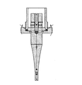
本発明の超音波振動付与具のフロントマスにホーンを介して工具が付設された超音波加工具のイメージを図7に示す。
すなわち、図7に示す超音波加工具は、先に図2乃至図5に図示した、超音波振動付与具にホーンを介して工具を装着した構成のものであるが、この場合でも、振動の節は増加するものの、図4と図5に示した超音波振動と同様なモードの超音波振動が発生する。 FIG. 7 shows an image of an ultrasonic processing tool in which a tool is attached to the front mass of the ultrasonic vibration imparting tool of the present invention via a horn.
That is, the ultrasonic processing tool shown in FIG. 7 has a configuration in which a tool is attached to the ultrasonic vibration imparting tool shown in FIGS. 2 to 5 via a horn, but even in this case, the vibration Although the number of nodes increases, ultrasonic vibration in a mode similar to the ultrasonic vibration shown in FIGS. 4 and 5 is generated.
Claims (5)
- 接触面を内周面下部もしくは底部に備え、そして外周面下部にねじ部を備えた円筒状ハウジング;この円筒状ハウジングの上記接触面に嵌め合わされる接触面を備えたフランジを上部に有し、下部に工具が装着される円柱状フロントマスと、そのフロントマスの上方に配置した円柱状リアマスとの間に分極処理済の圧電素子を挟んだ状態でボルト締めした構成のランジュバン型超音波振動子;そして、上記円筒状ハウジングのねじ部がねじ込まれるねじ部を内周面上部に有するリング状釣り合い重りを含む超音波振動付与具であって、このリング状釣り合い重りのねじ部の下側には内径が該ねじ部の内径よりも小さい下側小径部が形成されていて、その下側小径部の内周面と円柱状フロントマスの側面との間に空隙が形成された構成を持ち、円筒状ハウジングの円筒部の内周面が形成する円の半径(Hin)がリング状釣り合い重りの下側小径部の内周面が形成する円の半径(Nin)よりも大きく、その半径との差である(HN)が、上記フランジの下側表面に接する位置における円柱状フロントマスの半径(Fr)の0.01倍以上、1倍以下である超音波振動付与具。 Cylindrical housing with contact surfaces at the bottom or bottom of the inner peripheral surface and threads at the bottom of the outer peripheral surface; having a flange at the top with a contact surface fitted to the contact surface of the cylindrical housing. A flange van type ultrasonic transducer with a structure in which a polarized piezoelectric element is sandwiched between a cylindrical front mass on which a tool is mounted at the bottom and a cylindrical rear mass placed above the front mass and bolted. An ultrasonic vibration imparting tool including a ring-shaped balancing weight having a screw portion on the upper part of the inner peripheral surface into which the screw portion of the cylindrical housing is screwed, and below the threaded portion of the ring-shaped balancing weight. A lower small diameter portion having an inner diameter smaller than the inner diameter of the threaded portion is formed, and a gap is formed between the inner peripheral surface of the lower small diameter portion and the side surface of the cylindrical front mass, and the cylinder is cylindrical. The radius (Hin) of the circle formed by the inner peripheral surface of the cylindrical part of the cylindrical housing is larger than the radius (Nin) of the circle formed by the inner peripheral surface of the lower small diameter part of the ring-shaped balancing weight, and the difference from that radius. (HN) is 0.01 times or more and 1 times or less of the radius (Fr) of the cylindrical front mass at the position in contact with the lower surface of the flange.
- 円筒状ハウジングが鋼材から形成されている請求項1に記載の超音波振動付与具。 The ultrasonic vibration imparting tool according to claim 1, wherein the cylindrical housing is made of a steel material.
- 円筒状ハウジングの周囲あるいは上部に設けられた支持部材或いは保持部材によって支持或いは保持されている請求項1に記載の超音波振動付与具。 The ultrasonic vibration imparting tool according to claim 1, which is supported or held by a support member or a holding member provided around or above the cylindrical housing.
- リング状釣り合い重りのネジ部に、その外周面から内周面に貫通する3個もしくはそれ以上の貫通孔が形成されている請求項1に記載の超音波振動付与具。 The ultrasonic vibration imparting tool according to claim 1, wherein the threaded portion of the ring-shaped balancing weight is formed with three or more through holes penetrating from the outer peripheral surface to the inner peripheral surface thereof.
- フロントマスの下方に工具装着用開口部が形成されている請求項1に記載の超音波振動付与具。 The ultrasonic vibration imparting tool according to claim 1, wherein an opening for mounting a tool is formed below the front mass.
Priority Applications (1)
| Application Number | Priority Date | Filing Date | Title |
|---|---|---|---|
| JP2021513715A JPWO2020209362A1 (en) | 2019-04-11 | 2020-04-10 |
Applications Claiming Priority (2)
| Application Number | Priority Date | Filing Date | Title |
|---|---|---|---|
| JP2019087885 | 2019-04-11 | ||
| JP2019-087885 | 2019-04-11 |
Publications (1)
| Publication Number | Publication Date |
|---|---|
| WO2020209362A1 true WO2020209362A1 (en) | 2020-10-15 |
Family
ID=72751345
Family Applications (1)
| Application Number | Title | Priority Date | Filing Date |
|---|---|---|---|
| PCT/JP2020/016129 WO2020209362A1 (en) | 2019-04-11 | 2020-04-10 | Ultrasonic vibration adding tool |
Country Status (2)
| Country | Link |
|---|---|
| JP (1) | JPWO2020209362A1 (en) |
| WO (1) | WO2020209362A1 (en) |
Citations (6)
| Publication number | Priority date | Publication date | Assignee | Title |
|---|---|---|---|---|
| JPS63288601A (en) * | 1987-05-20 | 1988-11-25 | Taga Electric Co Ltd | Ultrasonic vibration cutting device |
| JP2001176932A (en) * | 1999-12-20 | 2001-06-29 | Matsushita Electric Ind Co Ltd | Ultrasonic vibrator |
| JP2010089007A (en) * | 2008-10-08 | 2010-04-22 | Sonotec Co Ltd | Ultrasonic machining apparatus |
| WO2017065263A1 (en) * | 2015-10-15 | 2017-04-20 | 有限会社Uwave | Oscillation excitation method for langevin ultrasonic transducer, ultrasonic machining method, and ultrasonic transmission method |
| JP2018038992A (en) * | 2016-09-05 | 2018-03-15 | 大西 一正 | Ultrasonic processing langevin-type ultrasonic vibrator, and support method therefor |
| JP2020028873A (en) * | 2018-08-20 | 2020-02-27 | 有限会社Uwave | Langevin type ultrasonic vibrator and method of supporting the same |
-
2020
- 2020-04-10 WO PCT/JP2020/016129 patent/WO2020209362A1/en active Application Filing
- 2020-04-10 JP JP2021513715A patent/JPWO2020209362A1/ja active Pending
Patent Citations (6)
| Publication number | Priority date | Publication date | Assignee | Title |
|---|---|---|---|---|
| JPS63288601A (en) * | 1987-05-20 | 1988-11-25 | Taga Electric Co Ltd | Ultrasonic vibration cutting device |
| JP2001176932A (en) * | 1999-12-20 | 2001-06-29 | Matsushita Electric Ind Co Ltd | Ultrasonic vibrator |
| JP2010089007A (en) * | 2008-10-08 | 2010-04-22 | Sonotec Co Ltd | Ultrasonic machining apparatus |
| WO2017065263A1 (en) * | 2015-10-15 | 2017-04-20 | 有限会社Uwave | Oscillation excitation method for langevin ultrasonic transducer, ultrasonic machining method, and ultrasonic transmission method |
| JP2018038992A (en) * | 2016-09-05 | 2018-03-15 | 大西 一正 | Ultrasonic processing langevin-type ultrasonic vibrator, and support method therefor |
| JP2020028873A (en) * | 2018-08-20 | 2020-02-27 | 有限会社Uwave | Langevin type ultrasonic vibrator and method of supporting the same |
Also Published As
| Publication number | Publication date |
|---|---|
| JPWO2020209362A1 (en) | 2020-10-15 |
Similar Documents
| Publication | Publication Date | Title |
|---|---|---|
| JP6863613B2 (en) | Ultrasonic vibration imparting tool and ultrasonic processing equipment | |
| US4173725A (en) | Piezoelectrically driven ultrasonic transducer | |
| CN108136441B (en) | Vibration exciting method for langevin type ultrasonic transducer, ultrasonic processing method, and ultrasonic transmission method | |
| JP4887492B2 (en) | Non-contact support device | |
| WO2020209362A1 (en) | Ultrasonic vibration adding tool | |
| JP6716082B2 (en) | Excitation method of longitudinal and torsional vibration of Langevin type ultrasonic transducer | |
| JP4827170B2 (en) | Bolt tightened Langevin type vibrator | |
| US7679266B2 (en) | Longitudinally driven slotted cylinder transducer | |
| WO2023195179A1 (en) | Ultrasonic wave radiation unit | |
| CN112188938B (en) | Ultrasonic vibration applying tool, traveling wave generating device, and ultrasonic machining device | |
| JP2017170361A (en) | Langevin type oscillator and active sonar equipped with langevin type oscillator | |
| JP2020028873A (en) | Langevin type ultrasonic vibrator and method of supporting the same | |
| JP2006198758A (en) | Ultrasonic vibration table | |
| WO2023181309A1 (en) | Vibrator unit and ultrasonic vacuum washing machine | |
| KR102159856B1 (en) | Ultrasonic device having large radiating area | |
| JP2020073274A (en) | Oscillation excitation method for langevin ultrasonic transducer, and ultrasonic machining method for material to be machined | |
| JP2006150329A (en) | Ultrasonic vibration table | |
| JPS6118299A (en) | Langevin vibrator tightened with bolt | |
| JP2020073275A (en) | Oscillation excitation method for langevin ultrasonic transducer, and ultrasonic machining method for material to be machined | |
| JP2006142468A (en) | Ultrasonic vibrating table | |
| JPH09155289A (en) | Bolted langevin type vibrator | |
| JP2006062069A (en) | Ultrasonic vibration table | |
| JP2005334984A (en) | Vibrating table | |
| JP2003018688A (en) | Tubular submersible sound source | |
| JPH06197400A (en) | Low frequency underwater transmitter |
Legal Events
| Date | Code | Title | Description |
|---|---|---|---|
| 121 | Ep: the epo has been informed by wipo that ep was designated in this application |
Ref document number: 20787782 Country of ref document: EP Kind code of ref document: A1 |
|
| ENP | Entry into the national phase |
Ref document number: 2021513715 Country of ref document: JP Kind code of ref document: A |
|
| NENP | Non-entry into the national phase |
Ref country code: DE |
|
| 122 | Ep: pct application non-entry in european phase |
Ref document number: 20787782 Country of ref document: EP Kind code of ref document: A1 |