WO2020209225A1 - Dispositif catalyseur - Google Patents
Dispositif catalyseur Download PDFInfo
- Publication number
- WO2020209225A1 WO2020209225A1 PCT/JP2020/015543 JP2020015543W WO2020209225A1 WO 2020209225 A1 WO2020209225 A1 WO 2020209225A1 JP 2020015543 W JP2020015543 W JP 2020015543W WO 2020209225 A1 WO2020209225 A1 WO 2020209225A1
- Authority
- WO
- WIPO (PCT)
- Prior art keywords
- downstream
- outer cylinder
- catalyst carrier
- exhaust pipe
- upstream
- Prior art date
Links
Images


Classifications
-
- F—MECHANICAL ENGINEERING; LIGHTING; HEATING; WEAPONS; BLASTING
- F01—MACHINES OR ENGINES IN GENERAL; ENGINE PLANTS IN GENERAL; STEAM ENGINES
- F01N—GAS-FLOW SILENCERS OR EXHAUST APPARATUS FOR MACHINES OR ENGINES IN GENERAL; GAS-FLOW SILENCERS OR EXHAUST APPARATUS FOR INTERNAL COMBUSTION ENGINES
- F01N3/00—Exhaust or silencing apparatus having means for purifying, rendering innocuous, or otherwise treating exhaust
- F01N3/08—Exhaust or silencing apparatus having means for purifying, rendering innocuous, or otherwise treating exhaust for rendering innocuous
- F01N3/10—Exhaust or silencing apparatus having means for purifying, rendering innocuous, or otherwise treating exhaust for rendering innocuous by thermal or catalytic conversion of noxious components of exhaust
- F01N3/24—Exhaust or silencing apparatus having means for purifying, rendering innocuous, or otherwise treating exhaust for rendering innocuous by thermal or catalytic conversion of noxious components of exhaust characterised by constructional aspects of converting apparatus
- F01N3/28—Construction of catalytic reactors
- F01N3/2803—Construction of catalytic reactors characterised by structure, by material or by manufacturing of catalyst support
- F01N3/2807—Metal other than sintered metal
- F01N3/281—Metallic honeycomb monoliths made of stacked or rolled sheets, foils or plates
-
- F—MECHANICAL ENGINEERING; LIGHTING; HEATING; WEAPONS; BLASTING
- F01—MACHINES OR ENGINES IN GENERAL; ENGINE PLANTS IN GENERAL; STEAM ENGINES
- F01N—GAS-FLOW SILENCERS OR EXHAUST APPARATUS FOR MACHINES OR ENGINES IN GENERAL; GAS-FLOW SILENCERS OR EXHAUST APPARATUS FOR INTERNAL COMBUSTION ENGINES
- F01N2330/00—Structure of catalyst support or particle filter
- F01N2330/02—Metallic plates or honeycombs, e.g. superposed or rolled-up corrugated or otherwise deformed sheet metal
-
- F—MECHANICAL ENGINEERING; LIGHTING; HEATING; WEAPONS; BLASTING
- F01—MACHINES OR ENGINES IN GENERAL; ENGINE PLANTS IN GENERAL; STEAM ENGINES
- F01N—GAS-FLOW SILENCERS OR EXHAUST APPARATUS FOR MACHINES OR ENGINES IN GENERAL; GAS-FLOW SILENCERS OR EXHAUST APPARATUS FOR INTERNAL COMBUSTION ENGINES
- F01N2330/00—Structure of catalyst support or particle filter
- F01N2330/30—Honeycomb supports characterised by their structural details
-
- F—MECHANICAL ENGINEERING; LIGHTING; HEATING; WEAPONS; BLASTING
- F01—MACHINES OR ENGINES IN GENERAL; ENGINE PLANTS IN GENERAL; STEAM ENGINES
- F01N—GAS-FLOW SILENCERS OR EXHAUST APPARATUS FOR MACHINES OR ENGINES IN GENERAL; GAS-FLOW SILENCERS OR EXHAUST APPARATUS FOR INTERNAL COMBUSTION ENGINES
- F01N2450/00—Methods or apparatus for fitting, inserting or repairing different elements
- F01N2450/22—Methods or apparatus for fitting, inserting or repairing different elements by welding or brazing
-
- F—MECHANICAL ENGINEERING; LIGHTING; HEATING; WEAPONS; BLASTING
- F01—MACHINES OR ENGINES IN GENERAL; ENGINE PLANTS IN GENERAL; STEAM ENGINES
- F01N—GAS-FLOW SILENCERS OR EXHAUST APPARATUS FOR MACHINES OR ENGINES IN GENERAL; GAS-FLOW SILENCERS OR EXHAUST APPARATUS FOR INTERNAL COMBUSTION ENGINES
- F01N2590/00—Exhaust or silencing apparatus adapted to particular use, e.g. for military applications, airplanes, submarines
- F01N2590/04—Exhaust or silencing apparatus adapted to particular use, e.g. for military applications, airplanes, submarines for motorcycles
-
- Y—GENERAL TAGGING OF NEW TECHNOLOGICAL DEVELOPMENTS; GENERAL TAGGING OF CROSS-SECTIONAL TECHNOLOGIES SPANNING OVER SEVERAL SECTIONS OF THE IPC; TECHNICAL SUBJECTS COVERED BY FORMER USPC CROSS-REFERENCE ART COLLECTIONS [XRACs] AND DIGESTS
- Y02—TECHNOLOGIES OR APPLICATIONS FOR MITIGATION OR ADAPTATION AGAINST CLIMATE CHANGE
- Y02A—TECHNOLOGIES FOR ADAPTATION TO CLIMATE CHANGE
- Y02A50/00—TECHNOLOGIES FOR ADAPTATION TO CLIMATE CHANGE in human health protection, e.g. against extreme weather
- Y02A50/20—Air quality improvement or preservation, e.g. vehicle emission control or emission reduction by using catalytic converters
Definitions
- the present invention relates to a catalyst device.
- the present application claims priority based on Japanese Patent Application No. 2019-075577 filed in Japan on April 11, 2019, the contents of which are incorporated herein by reference.
- the exhaust system of the internal combustion engine is provided with a catalyst device to purify the exhaust gas.
- a catalyst device metal catalyst converter
- a metal catalyst carrier formed by winding a corrugated plate and a flat plate is housed in an outer cylinder. It will be installed.
- the catalyst device described in Patent Document 1 only the outer periphery of the exhaust gas outflow side of the metal catalyst carrier is fixed to the inner circumference of the tubular support member, and the front part of the support member is the exhaust gas outflow side of the outer cylinder. It is inserted and fixed in.
- a gap is formed between the outer cylinder and the metal catalyst carrier, and this gap serves as an air heat insulating layer that keeps the metal catalyst carrier warm.
- the present invention provides a catalyst device with improved purification performance.
- the catalyst device internally supports a catalyst carrier (30) carrying a catalyst for purifying the exhaust gas discharged from the internal combustion engine (4) and the catalyst carrier (30).
- a downstream exhaust pipe (20) is provided with a gap (G) between the carrier (30) and the exhaust gas that has passed through the catalyst carrier (30).
- the air layer is provided between the downstream exhaust pipe and the catalyst carrier, that is, around the catalyst carrier, the influence of the outside air transmitted to the catalyst carrier via the downstream exhaust pipe is mitigated.
- the heat retention performance of the catalyst carrier can be improved.
- the exhaust gas heated by passing through the catalyst carrier flows into the gap between the downstream exhaust pipe and the catalyst carrier, compared with the configuration in which the exhaust gas that has not passed through the catalyst carrier flows in. ,
- the catalyst carrier can be surrounded by a hotter air layer. Therefore, the heat retention performance of the catalyst carrier can be reliably improved. Therefore, the catalyst can be activated at an early stage and the purification performance can be improved.
- the heat insulating structure can be thinned and the catalyst device can be miniaturized. Further, by providing a gap between the downstream exhaust pipe and the catalyst carrier, the outer cylinder that supports the catalyst carrier inside is miniaturized. Therefore, the amount of heat transferred to the outer cylinder when the temperature of the catalyst carrier is raised is reduced, so that the catalyst carrier can be activated more reliably at an early stage. Further, the weight of the catalyst device can be reduced by reducing the size of the outer cylinder.
- the downstream end portion (30d) of the catalyst carrier (30) is located downstream of the downstream end portion (40d) of the outer cylinder (40).
- the gap (G) is downstream of the downstream end (40d) of the outer cylinder (40), is outside the catalyst carrier (30), and is inside the downstream exhaust pipe (20). It may be provided in.
- a gap opens on the downstream side between the downstream end of the catalyst carrier and the inner peripheral surface of the downstream exhaust pipe. Therefore, since the gap between the downstream exhaust pipe and the catalyst carrier communicates with the space where the exhaust gas is discharged from the catalyst carrier, the exhaust gas that has passed through the catalyst carrier flows into the gap between the downstream exhaust pipe and the catalyst carrier. It becomes possible to make it.
- the joint portion of the outer cylinder with the downstream exhaust pipe is separated from the portion supporting the catalyst carrier, the joint portion between the outer cylinder and the downstream exhaust pipe is affected by the heat generation of the catalyst. Can be suppressed.
- the catalyst carrier (30) and the outer cylinder (40) are provided with a joint portion (B1), which is downstream of the joint portion (B1).
- the side end portion may be provided at the same position as the downstream side end portion (40d) of the outer cylinder (40).
- the outer cylinder can be shortened as compared with the case where the downstream end of the outer cylinder is located on the downstream side of the joint between the catalyst carrier and the outer cylinder. Therefore, the weight of the catalyst device can be reduced by reducing the size of the outer cylinder.
- the upstream exhaust pipe (10) through which the exhaust gas introduced into the catalyst carrier (30) flows and the outer cylinder (40).
- the welded portion (60) that joins the outer cylinder (40) and the upstream exhaust pipe (10) may be provided.
- the outer cylinder and the upstream exhaust pipe can be joined by a single welded portion, it is compared with the case where the outer cylinder and the collar member and the upstream exhaust pipe and the collar member are joined separately. Therefore, the manufacturing process can be simplified.
- the upstream end (40u) of the outer cylinder (40) is spaced apart from the downstream end (10d) of the upstream exhaust pipe (10). It may be arranged.
- a valley sandwiched between the upstream end of the outer cylinder and the downstream end of the upstream exhaust pipe is provided on the outside of the collar member. Therefore, the welded portion can be stably formed by filling the valley with the weld bead.
- the upstream end (20u) of the downstream exhaust pipe (20) is from the upstream end (40u) of the outer cylinder (40). May be located on the downstream side and joined to the outer cylinder (40) by the welded portion (60).
- the step of joining the downstream exhaust pipe and the outer cylinder can be summarized as the step of joining the outer cylinder and the upstream exhaust pipe. Therefore, the manufacturing process can be simplified. Moreover, since a step is formed between the upstream end of the downstream exhaust pipe and the upstream end of the outer cylinder, it is possible to stably form the weld by filling the step with a welding bead. it can.
- the outer diameter of the gap (G) may match the outer diameter of the outer cylinder (40).
- the inner diameters of the portion of the downstream exhaust pipe located outside the outer cylinder and the portion located outside the catalyst carrier are the same. Therefore, it is possible to provide a gap between the downstream exhaust pipe and the catalyst carrier without changing the inner diameter of the downstream exhaust pipe, so that a step for changing the inner diameter of the downstream exhaust pipe becomes unnecessary. Therefore, it is possible to prevent the manufacturing process from becoming complicated.
- the catalyst carrier (30) includes a flat plate (31) and a corrugated plate (32) wound in layers, and the flat plate (31) is provided. ) And the corrugated sheet (32) may be bonded to each other only at the upstream end portion (30u) of the catalyst carrier (30).
- the downstream exhaust pipe (20) is on the downstream side of the catalyst carrier (30), and gradually increases from the upstream side to the downstream side.
- a reduced diameter portion (22) for reducing the diameter may be integrally provided.
- a portion of the downstream exhaust pipe in which the catalyst carrier is arranged inside and a portion whose diameter is reduced toward the downstream end of the downstream exhaust pipe are made into a single component. Can be done. Therefore, the number of parts can be reduced.
- the purification performance can be improved.
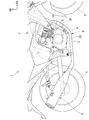
- FIG. 1 is a right side view showing a main part of a motorcycle equipped with an exhaust device of the embodiment.
- the motorcycle 1 includes an internal combustion engine 4 (engine) in the lower center of the vehicle between the front wheels 2 and the rear wheels 3.
- the internal combustion engine 4 includes a crankcase 5 and a cylinder portion 6 erected upward from the upper part of the crankcase 5.
- the crankcase 5 is supported by the vehicle body frame 7.
- An exhaust device 8 (catalyst device) is connected to the front portion of the cylinder portion 6.
- the exhaust device 8 purifies the exhaust gas discharged from the internal combustion engine 4.
- the purified exhaust gas is discharged through the muffler 9.
- the "upstream side” means the upstream side of the exhaust gas flow discharged from the internal combustion engine 4
- the "downstream side” means the downstream side of the exhaust gas flow discharged from the internal combustion engine 4. means.
- FIG. 2 is a cross-sectional view showing a main part of the exhaust device of the embodiment.
- the exhaust device 8 is formed in an elongated cylindrical shape as a whole.
- the exhaust device 8 includes an upstream exhaust pipe 10 connected to the cylinder portion 6 of the internal combustion engine 4, a downstream exhaust pipe 20 provided on the downstream side of the upstream exhaust pipe 10, and a catalyst carrier arranged in the downstream exhaust pipe 20.
- 30 and an outer cylinder 40 that connects to the downstream exhaust pipe 20 inside the downstream exhaust pipe 20 and supports the catalyst carrier 30 in the downstream exhaust pipe 20 are mainly provided.
- the upstream exhaust pipe 10 and the downstream exhaust pipe 20 form the main pipe of the exhaust device 8 and are connected to each other.
- Exhaust gas introduced into the catalyst carrier 30 flows through the upstream exhaust pipe 10.
- Exhaust gas that has passed through the catalyst carrier 30 flows through the downstream exhaust pipe 20.
- the diameter of the downstream portion of the upstream exhaust pipe 10 including the downstream end portion 10d is gradually increased from the upstream side to the downstream side.
- the upstream end portion 20u of the downstream exhaust pipe 20 faces the downstream end portion 10d of the upstream exhaust pipe 10 in the direction in which the exhaust gas flows.
- the inner diameter of the upstream end portion 20u of the downstream exhaust pipe 20 is larger than the inner diameter of the downstream end portion 10d of the upstream exhaust pipe 10.
- the downstream exhaust pipe 20 includes an upstream end portion 20u, is connected to an upstream portion 21 extending with a constant inner diameter and outer diameter on the downstream side, and is gradually reduced in diameter from the upstream side to the downstream side.
- the unit 22 and the unit 22 are integrally provided.
- the catalyst carrier 30 is arranged inside the upstream portion 21.
- the reduced diameter portion 22 is provided on the downstream side of the catalyst carrier 30.
- a muffler 9 is connected to the downstream end of the downstream exhaust pipe 20.
- the outer cylinder 40 is formed in a cylindrical shape.
- the outer diameter of the outer cylinder 40 coincides with the inner diameter of the upstream portion 21 of the downstream exhaust pipe 20.
- the outer cylinder 40 is densely inserted into the upstream end portion 20u of the downstream exhaust pipe 20.
- An upstream portion 21 of the downstream exhaust pipe 20 is connected to the outer cylinder 40 on the outside of the outer cylinder 40.
- the upstream end 40u of the outer cylinder 40 is located on the upstream side of the upstream end 20u of the downstream exhaust pipe 20. That is, the outer cylinder 40 projects upstream from the downstream exhaust pipe 20.
- a step is formed between the upstream end 40u of the outer cylinder 40 and the upstream end 20u of the downstream exhaust pipe 20.
- the upstream end 40u of the outer cylinder 40 is arranged at intervals on the downstream side of the downstream end 10d of the upstream exhaust pipe 10.
- the downstream end 40d of the outer cylinder 40 supports the catalyst carrier 30 inward.
- the catalyst carrier 30 is arranged inside the upstream portion 21 of the downstream exhaust pipe 20.
- the catalyst carrier 30 is formed in a columnar shape and extends in the direction in which the exhaust gas flows.
- the upstream end 30u of the catalyst carrier 30 is located on the downstream side of the upstream end 40u of the outer cylinder 40 and the upstream end 20u of the downstream exhaust pipe 20.
- the central portion of the catalyst carrier 30 is located on the downstream side of the downstream end portion 40d of the outer cylinder 40.
- the "central portion" in the present embodiment is a portion located equidistant from both ends of the target member.
- the downstream end portion 30d of the catalyst carrier 30 is located on the downstream side of the downstream end portion 40d of the outer cylinder 40 and on the upstream side of the downstream end portion of the upstream portion 21 of the downstream exhaust pipe 20.
- the catalyst carrier 30 is bonded to the outer cylinder 40.
- the outer peripheral surface of the upstream portion including the upstream end portion 30u of the catalyst carrier 30 is brazed to the inner peripheral surface of the outer cylinder 40.
- the joint portion B1 of the catalyst carrier 30 and the outer cylinder 40 coincides with the range in which the catalyst carrier 30 and the outer cylinder 40 overlap in the direction in which the exhaust gas flows. That is, the downstream end portion of the joint portion B1 of the catalyst carrier 30 and the outer cylinder 40 is provided at the same position as the downstream end portion 40d of the outer cylinder 40.
- FIG. 3 is an explanatory view of the catalyst carrier of the embodiment, and is a perspective view showing the catalyst carrier in the process of being formed.
- the catalyst carrier 30 includes a flat plate 31 and a corrugated plate 32 that are wound in layers, and is formed in a columnar shape having a honeycomb structure.
- the flat plate 31 and the corrugated plate 32 carry a catalyst for exhaust gas.
- the catalyst carrier 30 purifies and discharges the introduced exhaust gas by passing the exhaust gas inside the outermost flat plate 31.
- the flat plate 31 and the corrugated plate 32 forming the catalyst carrier 30 are joined to each other in a rolled state.
- the method of winding the catalyst carrier 30 is not limited to the method shown in FIG.
- the flat plate 31 and the corrugated plate 32 are joined to each other on the upstream side of the central portion of the catalyst carrier 30.
- the flat plate 31 and the corrugated plate 32 are joined to each other by brazing only at the upstream end portion 30u of the catalyst carrier 30.
- the joint range B2 between the flat plate 31 and the corrugated plate 32 is narrower than the joint portion B1 of the catalyst carrier 30 and the outer cylinder 40 in the direction in which the exhaust gas flows. That is, the downstream end of the joining range B2 of the flat plate 31 and the corrugated plate 32 is located upstream of the downstream end 40d of the outer cylinder 40.
- a gap G into which the exhaust gas that has passed through the catalyst carrier 30 flows is provided between the catalyst carrier 30 and the upstream portion 21 of the downstream exhaust pipe 20.
- the gap G is provided on the downstream side of the downstream end portion 40d of the outer cylinder 40, outside the catalyst carrier 30, and inside the upstream portion 21 of the downstream exhaust pipe 20.
- the outer diameter of the gap G matches the outer diameter of the outer cylinder 40.
- the gap G opens on the downstream side and communicates with the space where the exhaust gas is discharged from the catalyst carrier 30.
- the gap G is continuously provided over the entire circumference of the catalyst carrier 30.
- the exhaust device 8 further includes a collar member 50 and a welded portion 60 for connecting the upstream exhaust pipe 10, the downstream exhaust pipe 20, and the outer cylinder 40.
- the collar member 50 is formed in a cylindrical shape.
- the collar member 50 is arranged from the inside of the upstream end 40u of the outer cylinder 40 to the inside of the downstream end 10d of the upstream exhaust pipe 10.
- the outer diameter of the collar member 50 matches the inner diameter of the outer cylinder 40.
- the collar member 50 is inserted into the upstream end portion 40u of the outer cylinder 40.
- the downstream end portion 50d of the collar member 50 is located on the upstream side of the upstream end portion 30u of the catalyst carrier 30.
- the collar member 50 is provided so as to project upstream from the outer cylinder 40.
- a step is formed between the upstream end 50u of the collar member 50 and the upstream end 40u of the outer cylinder 40.
- the upstream end 50u of the collar member 50 is inserted into the downstream end 10d of the upstream exhaust pipe 10.
- a valley V sandwiched between the downstream end portion 10d of the upstream exhaust pipe 10 and the upstream end portion 40u of the outer cylinder 40 extends in an annular shape on the outside of the collar member 50.
- the welded portion 60 is provided on the outside of the collar member 50.
- the welded portion 60 is a weld bead provided so as to fill the valley V on the outer side of the collar member 50.
- the welded portion 60 is provided on the upstream side of the catalyst carrier 30.
- the welded portion 60 is provided so as to cover the downstream end portion 10d of the upstream exhaust pipe 10, the upstream end portion 40u of the outer cylinder 40, and the upstream side end portion 20u of the downstream exhaust pipe 20.
- the welded portion 60 joins the downstream end portion 10d of the upstream exhaust pipe 10 with the collar member 50, the upstream end portion 40u of the outer cylinder 40, and the upstream end portion 20u of the downstream exhaust pipe 20.
- the welded portion 60 airtightly joins the upstream exhaust pipe 10 and the collar member 50.
- the welded portion 60 joins the collar member 50 and the outer cylinder 40, and also joins the outer cylinder 40 and the downstream exhaust pipe 20.
- the welded portion 60 closes between the outer peripheral surface of the collar member 50 and the inner peripheral surface of the outer cylinder 40 from the upstream side.
- the welded portion 60 closes between the outer peripheral surface of the outer cylinder 40 and the inner peripheral surface of the downstream exhaust pipe 20 from the upstream side.
- the exhaust device 8 of the present embodiment is connected between the outer cylinder 40 that supports the catalyst carrier 30 inside and the outer cylinder 40 on the outside of the outer cylinder 40, and between the catalyst carrier 30.
- a downstream exhaust pipe 20 provided with a gap G into which exhaust gas that has passed through the catalyst carrier 30 flows in is provided. According to this configuration, since the air layer is provided between the downstream exhaust pipe 20 and the catalyst carrier 30, that is, around the catalyst carrier 30, the influence of the outside air transmitted to the catalyst carrier 30 via the downstream exhaust pipe 20 is mitigated. Therefore, the heat retention performance of the catalyst carrier 30 can be improved.
- the exhaust gas heated by passing through the catalyst carrier 30 flows into the gap G between the downstream exhaust pipe 20 and the catalyst carrier 30, the exhaust gas that has not passed through the catalyst carrier flows into the gap G.
- the catalyst carrier 30 can be surrounded by a hotter air layer. Therefore, the heat retention performance of the catalyst carrier 30 can be reliably improved. Therefore, the catalyst can be activated at an early stage and the purification performance can be improved. Further, since the heat retention performance of the catalyst carrier 30 is improved, the heat insulating structure can be thinned and the exhaust device 8 can be miniaturized. Further, by providing a gap G between the downstream exhaust pipe 20 and the catalyst carrier 30, the outer cylinder 40 that supports the catalyst carrier 30 inward is miniaturized.
- the amount of heat transferred to the outer cylinder 40 decreases when the temperature of the catalyst carrier 30 rises, so that the catalyst carrier 30 can be activated more reliably at an early stage. Further, the weight of the exhaust device 8 can be reduced by reducing the size of the outer cylinder 40.
- the downstream end portion 30d of the catalyst carrier 30 is located on the downstream side of the downstream end portion 40d of the outer cylinder 40.
- the gap G is provided on the downstream side of the downstream end portion 40d of the outer cylinder 40, outside the catalyst carrier 30, and inside the downstream exhaust pipe 20. According to this configuration, a gap G opens on the downstream side between the downstream end portion 30d of the catalyst carrier 30 and the inner peripheral surface of the downstream exhaust pipe 20. Therefore, since the gap G between the downstream exhaust pipe 20 and the catalyst carrier 30 communicates with the space where the exhaust gas is discharged from the catalyst carrier 30, the exhaust gas that has passed through the catalyst carrier 30 is passed through the downstream exhaust pipe 20 and the catalyst carrier 30. It is possible to flow into the gap G between the and.
- downstream exhaust pipe 20 is joined to the outer cylinder 40 on the upstream side of the catalyst carrier 30.
- the joint portion that is, the welded portion 60
- the downstream exhaust pipe 20 in the outer cylinder 40 is separated from the portion supporting the catalyst carrier 30. Therefore, it is possible to prevent the joint portion between the outer cylinder 40 and the downstream exhaust pipe 20 from being affected by the heat generated by the catalyst.
- downstream end portion of the joint portion B1 of the catalyst carrier 30 and the outer cylinder 40 is provided at the same position as the downstream end portion 40d of the outer cylinder 40.
- the outer cylinder 40 can be shortened as compared with the case where the downstream end portion of the outer cylinder is located on the downstream side of the joint portion between the catalyst carrier and the outer cylinder. Therefore, the weight of the exhaust device 8 can be reduced by reducing the size of the outer cylinder 40.
- the exhaust device 8 is provided outside the collar member 50 arranged from the inside of the upstream end 40u of the outer cylinder 40 to the inside of the downstream end 10d of the upstream exhaust pipe 10 and outside the collar member 50.
- a welded portion 60 for joining the cylinder 40 and the upstream exhaust pipe 10 is provided. According to this configuration, the outer cylinder 40 and the upstream exhaust pipe 10 can be joined by a single welded portion 60. Therefore, when the outer cylinder 40 and the collar member 50 and the upstream exhaust pipe 10 and the collar member 50 are joined separately. The manufacturing process can be simplified as compared with.
- the upstream end 40u of the outer cylinder 40 is arranged at intervals 10d on the downstream end 10d of the upstream exhaust pipe 10, the upstream end 40u of the outer cylinder 40 is outside the collar member 50. And a valley V sandwiched between the upstream exhaust pipe 10 and the downstream end portion 10d of the upstream exhaust pipe 10 are provided. Therefore, the welded portion 60 can be stably formed by filling the valley V with the weld bead.
- the upstream end portion 20u of the downstream exhaust pipe 20 is located on the downstream side of the upstream end portion 40u of the outer cylinder 40, and is joined to the outer cylinder 40 by a welded portion 60.
- the step of joining the downstream exhaust pipe 20 and the outer cylinder 40 can be summarized as the step of joining the outer cylinder 40 and the upstream exhaust pipe 10. Therefore, the manufacturing process can be simplified.
- the step is filled with a welding bead to stabilize the weld 60. Can be formed.
- the outer diameter of the gap G matches the outer diameter of the outer cylinder 40. According to this configuration, the inner diameters of the portion of the downstream exhaust pipe 20 located outside the outer cylinder 40 and the portion located outside the catalyst carrier 30 match. Therefore, it is possible to provide a gap G between the downstream exhaust pipe 20 and the catalyst carrier 30 without changing the inner diameter of the downstream exhaust pipe 20, so that a step for changing the inner diameter of the downstream exhaust pipe 20. Is unnecessary. Therefore, it is possible to prevent the manufacturing process from becoming complicated.
- the catalyst carrier 30 is formed by overlapping the flat plate 31 and the corrugated plate 32, and the flat plate 31 and the corrugated plate 32 are bonded to each other only at the upstream end portion 30u of the catalyst carrier 30. According to this configuration, deformation of the catalyst carrier 30 due to a temperature change is allowed on the downstream side of the upstream end portion 30u, so that the thermal stress generated on the catalyst carrier 30 can be reduced.
- the downstream exhaust pipe 20 integrally has a diameter-reduced portion 22 on the downstream side of the catalyst carrier 30, which gradually reduces in diameter from the upstream side to the downstream side.
- the portion of the downstream exhaust pipe 20 where the catalyst carrier 30 is arranged inside upstream portion 21
- the portion of the downstream exhaust pipe whose diameter is reduced toward the 20 downstream end portion can be a single component. Therefore, the number of parts can be reduced.
- the present invention is not limited to the above-described embodiment described with reference to the drawings, and various modifications can be considered within the technical scope thereof.
- the catalyst device of the present invention can be mounted on various vehicles having an internal combustion engine, and may be applied to, for example, an exhaust device for a three-wheeled vehicle or a four-wheeled vehicle.
- the flat plate 31 and the corrugated plate 32 of the catalyst carrier 30 are joined to each other by brazing, but the present invention is not limited to this.
- the flat plate 31 and the corrugated plate 32 may be joined to each other by diffusion bonding. The same applies to the bonding between the catalyst carrier 30 and the outer cylinder 40.
- the upstream end portion 50u of the collar member 50 is inserted into the downstream end portion 10d of the upstream exhaust pipe 10, but the present invention is not limited to this.
- the collar member and the upstream exhaust pipe may be airtightly joined to each other.
- the upstream end of the collar member is arranged at the same position as the downstream end of the upstream exhaust pipe in the direction of exhaust gas flow. May be.
- the collar member and the upstream exhaust pipe may be a single member integrally formed.
- the catalyst carrier 30 is arranged in front of the internal combustion engine 4, but the position of the catalyst carrier 30 is not particularly limited.
- the catalyst carrier 30 may be arranged below the internal combustion engine 4.
- the entire exhaust device 8 is used as the catalyst device of the present invention, but the present invention is not limited to this.
- the catalyst device may be part of an exhaust system.
- the exhaust device may further include a heat shield pipe for the outside provided so as to cover the upstream portion 21 of the downstream exhaust pipe 20 around the catalyst carrier 30.
- Exhaust system (catalyst device) 10 Upstream exhaust pipe 10d Downstream end of upstream exhaust pipe 20 Downstream exhaust pipe 20u Upstream end of downstream exhaust pipe 22 Reduced diameter part 30 Catalyst carrier 30d Downstream end of catalyst carrier 30u Upstream end of catalyst carrier 31 Flat plate 32 Corrugated plate 40 Outer cylinder 40d Downstream end of outer cylinder 40u Upstream end of outer cylinder 50 Color member 60 Welded part B1 Joint part G Gap
Abstract
Un dispositif catalyseur (8) comprend : un support de catalyseur (30) qui supporte un catalyseur pour purifier un gaz d'échappement évacué d'un moteur à combustion interne; un tube externe (40) qui supporte le support de catalyseur (30) à l'intérieur de celui-ci; et un tuyau d'échappement en aval (20) qui est un tuyau d'échappement à travers lequel un gaz d'échappement qui a traversé le support de catalyseur (30) s'écoule, qui est relié au tube externe (40) sur l'extérieur du tube externe (40), et qui a un espace (G) avec le support de catalyseur (30) dans lequel s'écoule le gaz d'échappement qui a traversé le support de catalyseur (30).
Priority Applications (3)
| Application Number | Priority Date | Filing Date | Title |
|---|---|---|---|
| DE112020001841.5T DE112020001841T5 (de) | 2019-04-11 | 2020-04-06 | Katalysatoreinrichtung |
| JP2021513626A JP7138784B2 (ja) | 2019-04-11 | 2020-04-06 | 触媒装置 |
| CN202090000473.0U CN216137016U (zh) | 2019-04-11 | 2020-04-06 | 催化装置 |
Applications Claiming Priority (2)
| Application Number | Priority Date | Filing Date | Title |
|---|---|---|---|
| JP2019-075577 | 2019-04-11 | ||
| JP2019075577 | 2019-04-11 |
Publications (1)
| Publication Number | Publication Date |
|---|---|
| WO2020209225A1 true WO2020209225A1 (fr) | 2020-10-15 |
Family
ID=72751639
Family Applications (1)
| Application Number | Title | Priority Date | Filing Date |
|---|---|---|---|
| PCT/JP2020/015543 WO2020209225A1 (fr) | 2019-04-11 | 2020-04-06 | Dispositif catalyseur |
Country Status (4)
| Country | Link |
|---|---|
| JP (1) | JP7138784B2 (fr) |
| CN (1) | CN216137016U (fr) |
| DE (1) | DE112020001841T5 (fr) |
| WO (1) | WO2020209225A1 (fr) |
Citations (4)
| Publication number | Priority date | Publication date | Assignee | Title |
|---|---|---|---|---|
| JPS5482215U (fr) * | 1977-11-21 | 1979-06-11 | ||
| JPH0679181A (ja) * | 1992-09-04 | 1994-03-22 | Toyota Motor Corp | 排気ガス浄化触媒用メタル担体 |
| JPH10337A (ja) * | 1996-06-19 | 1998-01-06 | Nippon Steel Corp | 金属製触媒コンバータおよびその製造方法 |
| JP2010156213A (ja) * | 2008-12-26 | 2010-07-15 | Futaba Industrial Co Ltd | 排気浄化装置 |
Family Cites Families (4)
| Publication number | Priority date | Publication date | Assignee | Title |
|---|---|---|---|---|
| JPH01162017U (fr) * | 1988-04-30 | 1989-11-10 | ||
| JPH0791239A (ja) * | 1993-09-20 | 1995-04-04 | Calsonic Corp | 金属触媒コンバータ |
| JP5482215B2 (ja) | 2010-01-19 | 2014-05-07 | コニカミノルタ株式会社 | 画像形成装置 |
| JP6879290B2 (ja) | 2018-12-26 | 2021-06-02 | 日亜化学工業株式会社 | 発光装置 |
-
2020
- 2020-04-06 WO PCT/JP2020/015543 patent/WO2020209225A1/fr active Application Filing
- 2020-04-06 DE DE112020001841.5T patent/DE112020001841T5/de active Pending
- 2020-04-06 CN CN202090000473.0U patent/CN216137016U/zh active Active
- 2020-04-06 JP JP2021513626A patent/JP7138784B2/ja active Active
Patent Citations (4)
| Publication number | Priority date | Publication date | Assignee | Title |
|---|---|---|---|---|
| JPS5482215U (fr) * | 1977-11-21 | 1979-06-11 | ||
| JPH0679181A (ja) * | 1992-09-04 | 1994-03-22 | Toyota Motor Corp | 排気ガス浄化触媒用メタル担体 |
| JPH10337A (ja) * | 1996-06-19 | 1998-01-06 | Nippon Steel Corp | 金属製触媒コンバータおよびその製造方法 |
| JP2010156213A (ja) * | 2008-12-26 | 2010-07-15 | Futaba Industrial Co Ltd | 排気浄化装置 |
Also Published As
| Publication number | Publication date |
|---|---|
| DE112020001841T5 (de) | 2021-12-30 |
| JP7138784B2 (ja) | 2022-09-16 |
| JPWO2020209225A1 (fr) | 2020-10-15 |
| CN216137016U (zh) | 2022-03-29 |
Similar Documents
| Publication | Publication Date | Title |
|---|---|---|
| US7484361B2 (en) | Exhaust gas purifying apparatus of motorcycle | |
| JP4538380B2 (ja) | 自動二輪車の排気装置 | |
| US20130199869A1 (en) | Exhaust muffler device | |
| JP2006070705A (ja) | 車両用エンジンの排気装置 | |
| US8091349B2 (en) | Motorcycle | |
| JP6114244B2 (ja) | 車両の排気装置 | |
| JP2006077727A (ja) | 自動二輪車の排気装置 | |
| JP2013204424A (ja) | 排気ガス浄化用触媒コンバーター装置及び鞍乗り型車両 | |
| JPH0874566A (ja) | エンジンの排気浄化装置 | |
| WO2020209225A1 (fr) | Dispositif catalyseur | |
| JP3795651B2 (ja) | 触媒コンバータ装置およびこれを備えた排気ガスシステム | |
| JP6027748B2 (ja) | 排気マフラー装置 | |
| CN1896469B (zh) | 消声器结构 | |
| JP6126564B2 (ja) | 車両に搭載される触媒付き排気管 | |
| JPH1113463A (ja) | 排気ガスシステム | |
| JP2020133477A (ja) | 排気マフラー構造 | |
| JPH11511697A (ja) | ジャケットチューブに部分的にのみ結合されたハニカム状の本体 | |
| JP6969008B2 (ja) | 鞍乗り型車両用内燃機関の排気装置 | |
| JP4917464B2 (ja) | 車両の排気装置 | |
| TW593870B (en) | Exhaust system for motorcycle | |
| JP5143156B2 (ja) | エンジンの排気装置のサブアッセンブリー | |
| JP3699209B2 (ja) | 排気ガス浄化装置 | |
| JP3644762B2 (ja) | 排気ガス浄化装置 | |
| JP4381916B2 (ja) | 自動二輪車の内燃機関用消音器 | |
| WO2022138273A1 (fr) | Dispositif catalytique métallique |
Legal Events
| Date | Code | Title | Description |
|---|---|---|---|
| 121 | Ep: the epo has been informed by wipo that ep was designated in this application |
Ref document number: 20787884 Country of ref document: EP Kind code of ref document: A1 |
|
| ENP | Entry into the national phase |
Ref document number: 2021513626 Country of ref document: JP Kind code of ref document: A |
|
| 122 | Ep: pct application non-entry in european phase |
Ref document number: 20787884 Country of ref document: EP Kind code of ref document: A1 |