WO2020209203A1 - 気化装置の置き換え方法 - Google Patents
気化装置の置き換え方法 Download PDFInfo
- Publication number
- WO2020209203A1 WO2020209203A1 PCT/JP2020/015371 JP2020015371W WO2020209203A1 WO 2020209203 A1 WO2020209203 A1 WO 2020209203A1 JP 2020015371 W JP2020015371 W JP 2020015371W WO 2020209203 A1 WO2020209203 A1 WO 2020209203A1
- Authority
- WO
- WIPO (PCT)
- Prior art keywords
- heat exchanger
- heat
- vaporized gas
- vaporizer
- existing
- Prior art date
- Legal status (The legal status is an assumption and is not a legal conclusion. Google has not performed a legal analysis and makes no representation as to the accuracy of the status listed.)
- Ceased
Links
Images




Classifications
-
- B—PERFORMING OPERATIONS; TRANSPORTING
- B65—CONVEYING; PACKING; STORING; HANDLING THIN OR FILAMENTARY MATERIAL
- B65D—CONTAINERS FOR STORAGE OR TRANSPORT OF ARTICLES OR MATERIALS, e.g. BAGS, BARRELS, BOTTLES, BOXES, CANS, CARTONS, CRATES, DRUMS, JARS, TANKS, HOPPERS, FORWARDING CONTAINERS; ACCESSORIES, CLOSURES, OR FITTINGS THEREFOR; PACKAGING ELEMENTS; PACKAGES
- B65D90/00—Component parts, details or accessories for large containers
- B65D90/12—Supports
-
- E—FIXED CONSTRUCTIONS
- E02—HYDRAULIC ENGINEERING; FOUNDATIONS; SOIL SHIFTING
- E02D—FOUNDATIONS; EXCAVATIONS; EMBANKMENTS; UNDERGROUND OR UNDERWATER STRUCTURES
- E02D27/00—Foundations as substructures
- E02D27/32—Foundations for special purposes
- E02D27/38—Foundations for large tanks, e.g. oil tanks
-
- F—MECHANICAL ENGINEERING; LIGHTING; HEATING; WEAPONS; BLASTING
- F17—STORING OR DISTRIBUTING GASES OR LIQUIDS
- F17C—VESSELS FOR CONTAINING OR STORING COMPRESSED, LIQUEFIED OR SOLIDIFIED GASES; FIXED-CAPACITY GAS-HOLDERS; FILLING VESSELS WITH, OR DISCHARGING FROM VESSELS, COMPRESSED, LIQUEFIED, OR SOLIDIFIED GASES
- F17C9/00—Methods or apparatus for discharging liquefied or solidified gases from vessels not under pressure
- F17C9/02—Methods or apparatus for discharging liquefied or solidified gases from vessels not under pressure with change of state, e.g. vaporisation
-
- F—MECHANICAL ENGINEERING; LIGHTING; HEATING; WEAPONS; BLASTING
- F28—HEAT EXCHANGE IN GENERAL
- F28D—HEAT-EXCHANGE APPARATUS, NOT PROVIDED FOR IN ANOTHER SUBCLASS, IN WHICH THE HEAT-EXCHANGE MEDIA DO NOT COME INTO DIRECT CONTACT
- F28D5/00—Heat-exchange apparatus having stationary conduit assemblies for one heat-exchange medium only, the media being in contact with different sides of the conduit wall, using the cooling effect of natural or forced evaporation
- F28D5/02—Heat-exchange apparatus having stationary conduit assemblies for one heat-exchange medium only, the media being in contact with different sides of the conduit wall, using the cooling effect of natural or forced evaporation in which the evaporating medium flows in a continuous film or trickles freely over the conduits
-
- F—MECHANICAL ENGINEERING; LIGHTING; HEATING; WEAPONS; BLASTING
- F28—HEAT EXCHANGE IN GENERAL
- F28D—HEAT-EXCHANGE APPARATUS, NOT PROVIDED FOR IN ANOTHER SUBCLASS, IN WHICH THE HEAT-EXCHANGE MEDIA DO NOT COME INTO DIRECT CONTACT
- F28D7/00—Heat-exchange apparatus having stationary tubular conduit assemblies for both heat-exchange media, the media being in contact with different sides of a conduit wall
- F28D7/16—Heat-exchange apparatus having stationary tubular conduit assemblies for both heat-exchange media, the media being in contact with different sides of a conduit wall the conduits being arranged in parallel spaced relation
-
- F—MECHANICAL ENGINEERING; LIGHTING; HEATING; WEAPONS; BLASTING
- F28—HEAT EXCHANGE IN GENERAL
- F28D—HEAT-EXCHANGE APPARATUS, NOT PROVIDED FOR IN ANOTHER SUBCLASS, IN WHICH THE HEAT-EXCHANGE MEDIA DO NOT COME INTO DIRECT CONTACT
- F28D9/00—Heat-exchange apparatus having stationary plate-like or laminated conduit assemblies for both heat-exchange media, the media being in contact with different sides of a conduit wall
-
- F—MECHANICAL ENGINEERING; LIGHTING; HEATING; WEAPONS; BLASTING
- F28—HEAT EXCHANGE IN GENERAL
- F28F—DETAILS OF HEAT-EXCHANGE AND HEAT-TRANSFER APPARATUS, OF GENERAL APPLICATION
- F28F1/00—Tubular elements; Assemblies of tubular elements
- F28F1/10—Tubular elements and assemblies thereof with means for increasing heat-transfer area, e.g. with fins, with projections, with recesses
- F28F1/12—Tubular elements and assemblies thereof with means for increasing heat-transfer area, e.g. with fins, with projections, with recesses the means being only outside the tubular element
- F28F1/24—Tubular elements and assemblies thereof with means for increasing heat-transfer area, e.g. with fins, with projections, with recesses the means being only outside the tubular element and extending transversely
- F28F1/32—Tubular elements and assemblies thereof with means for increasing heat-transfer area, e.g. with fins, with projections, with recesses the means being only outside the tubular element and extending transversely the means having portions engaging further tubular elements
Definitions
- the present invention relates to a method of replacing an existing vaporizer with a new vaporizer.
- An open rack type vaporizer having a heat exchanger configured to vaporize the liquefied gas by supplying a heating liquid to the outer peripheral surface of the heat transfer tube through which the liquefied gas is flowing is known ( See Patent Documents 1 and 2).
- the basic structure used for installing the heat exchanger of the existing vaporizer is also used for the new vaporizer.
- the foundation structure is reused, it may be difficult to increase the capacity of the new vaporizer.
- the size of the new vaporizer cannot be significantly increased from the size of the existing vaporizer. If an increase in the size of the new vaporizer is unacceptable, then measures such as increasing the number of heat transfer tubes, lengthening the heat transfer tubes, or increasing the number of heat transfer panels cannot be taken, and the vaporization capacity will increase. Be restricted.
- the present invention provides a technique that makes it possible to install a new vaporizer having a vaporization ability superior to that of the existing vaporizer while utilizing the basic structure of the heat exchanger of the existing vaporizer. The purpose.
- the liquefied gas is vaporized to generate the vaporized gas by supplying the heating liquid to the outer peripheral surface of the heat transfer tube through which the liquefied gas is flowing. It can be used to replace an existing vaporizer with a heat exchanger that raises the temperature of the vaporized gas with a new vaporizer.
- the replacement method is to vaporize the liquefied gas by removing the heat exchanger of the existing vaporizer from the basic structure and supplying a heating liquid to the outer peripheral surface of the heat transfer tube through which the liquefied gas is flowing.
- a first heat exchanger equipped with one or more open rack heat exchangers configured to allow the heat exchanger to be installed on the basic structure from which the heat exchanger has been removed and obtained as a result of vaporization of the liquefied gas.
- a second heat exchanger for raising the temperature of the vaporized gas is installed in a place different from the basic structure, and the vaporized gas flows from the first heat exchanger into the second heat exchanger.
- the first heat exchanger is connected to the second heat exchanger, and the supply amount of the liquefied gas supplied to the first heat exchanger is supplied to the heat exchanger of the existing vaporizer.
- the above-mentioned replacement method makes it possible to install a new vaporizer having a better vaporizing ability than the existing vaporizer by utilizing the basic structure of the heat exchanger of the existing vaporizer.
- FIG. 5 is a schematic cross-sectional view of another heat exchanger that can be used as the second heat exchanger of the new vaporizer.
- FIG. 5 is a schematic perspective view of another heat exchanger that can be used as the second heat exchanger of the new vaporizer.
- FIG. 5 is a schematic layout diagram of another heat exchanger that can be used as the second heat exchanger of the new vaporizer.
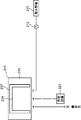
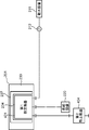
- It is a schematic layout diagram of an existing vaporizer. It is a schematic layout figure which shows the removal process. It is a schematic layout figure which shows the installation process. It is a schematic layout figure which shows the connection process.
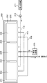
- FIG. 1 is a schematic layout diagram of the existing vaporizer 100.
- the existing vaporizer 100 will be described with reference to FIG.
- the vaporizer 100 includes three heat exchangers 111, 112, 113 arranged at intervals on the foundation structure 200, and three manifolds 114, 115 connected to these heat exchangers 111, 112, 113. , 116 and.
- Each of the heat exchangers 111, 112, and 113 is installed to vaporize the liquefied gas through heat exchange between the seawater and the liquefied gas to generate the vaporized gas.
- Manifolds 114, 115, 116 are used to supply seawater and liquefied gas to these heat exchangers 111, 112, 113 and to recover vaporized gas from these heat exchangers 111, 112, 113.
- the manifolds 114, 115, 116 extend outside the foundation structure 200 in the alignment direction of the heat exchangers 111, 112, 113. Manifolds 114, 115, 116 are connected to heat exchangers 111, 112, 113, respectively.
- the manifold 114 is connected to a seawater pump 212 that discharges seawater taken by the water intake facility 211.
- the seawater supply route is drawn with a dotted line in FIG.
- the manifold 115 is connected to a supply facility 220 that supplies liquefied gas.
- the amount of liquefied gas supplied from the supply facility 220 is set to a predetermined value based on the amount of vaporized gas required by the demand destination.
- the supply path of the liquefied gas is drawn by a chain line in FIG.
- the vaporized gas generated by the heat exchangers 111, 112, and 113 flows into the manifold 116.
- the manifold 116 is connected to a pipe member extending from a demand destination that requires vaporized gas.
- the flow path of the vaporized gas is drawn by a solid line in FIG.
- the basic structure 200 is used to fix the heat exchangers 111, 112, 113.
- the foundation structure 200 includes a base portion 230 formed on the ground and a foundation frame 231 erected from the base portion 230.
- the base frame 231 includes an outer frame 232 formed in a substantially C shape in a plan view, and two partition frames 233 that partition the area surrounded by the outer frame 232 into three installation areas 234, 235 and 236. There is.
- the heat exchangers 111, 112, 113 have an open rack type structure and are structurally common. The structure of the heat exchangers 111, 112, 113 will be described with reference to FIGS. 1 and 2.
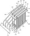
- FIG. 2 is a schematic perspective view of the open rack type vaporizer 300 included in each of the heat exchangers 111, 112, and 113. Each of the heat exchangers 111, 112, and 113 may have only one open rack type vaporizer 300, or may have two or more open rack type vaporizers 300.
- the open rack type vaporizer 300 is configured to generate vaporized gas at a temperature higher than the temperature required by the demand destination when a predetermined flow rate of liquefied gas is supplied from the supply facility 220.
- the open rack vaporizer 300 includes three heat transfer panels 310, four supply pipes 321 extending directly or indirectly from the manifold 114, and four troughs 322 connected to these supply pipes 321 respectively. And is included.
- the open rack vaporizer 300 has a pair of manifolds 315,316.
- the manifold 315 is connected to the manifold 115 described with reference to FIG. 1 (see FIG. 1).
- the manifold 316 is connected to the manifold 116 described with reference to FIG.
- the four troughs 322 are spaced apart from each other in the width direction of the opening portion of the base frame 231.
- the heat transfer panel 310 is erected between the troughs 322. Therefore, the three heat transfer panels 310 are also arranged in the width direction of the opening portion of the base frame 231 at intervals.
- Each of the three heat transfer panels 310 is substantially vertical between the lower header tube 311 and the upper header tube 312 arranged above the lower header tube 311 and between the lower header tube 311 and the upper header tube 312. Includes a plurality of heat transfer tubes 313 extending to.
- the lower header pipe 311 extends from the liquefied gas manifold 315 and enters the installation area 234, 235, 236.
- the upper header pipe 312 extends from the vaporized gas manifold 316 and enters the installation area 234, 235, 236.
- the plurality of heat transfer tubes 313 are aligned in the extending direction of the lower header tube 311 and the upper header tube 312.
- Each of the four troughs 322 is used to supply seawater to the corresponding heat transfer panel 310.
- the trough 322 and the corresponding heat transfer panel 310 form an open rack vaporizer.
- the trough 322 has a box-shaped structure that is long in the alignment direction of the heat transfer tubes 313, and is open upward.
- the trough 322 is arranged at a position lower than the upper header tube 312 and higher than the intermediate position of the heat transfer panel 310 in the vertical direction, and is adjacent to the upper part of the plurality of heat transfer tubes 313.
- the four supply pipes 321 are connected to the four troughs 322 and the manifold 114 for seawater to form a seawater supply path.
- Seawater is taken in by the water intake facility 211 and then sent out to the manifold 114 by the seawater pump 212.
- the seawater is distributed by the manifold 114 to the four supply pipes 321 of the heat exchangers 111, 112, and 113, respectively.
- Seawater is supplied to each of the four troughs 322 of the heat exchangers 111, 112, 113 through these supply pipes 321.
- Seawater overflows from the trough 322 and is supplied to the upper part of the outer peripheral surface of the plurality of heat transfer tubes 313.
- Seawater flows down along the outer peripheral surface of these heat transfer tubes 313.
- the amount of seawater supplied is set so that vaporized gas having a temperature higher than the temperature required by the demand destination can be obtained.
- the liquefied gas is supplied from the supply facility 220 to the manifolds 115 and 315, and is distributed by the manifold 315 to the lower header pipes 311 of the heat exchangers 111, 112 and 113, respectively.
- the liquefied gas flows from the lower header pipe 311 into the plurality of heat transfer pipes 313 and heads toward the upper header pipe 312.
- the liquefied gas exchanges heat with the seawater flowing down along the outer peripheral surfaces of the plurality of heat transfer tubes 313 and becomes vaporized gas.
- the vaporized gas sequentially passes through the upper header pipe 312 and the manifolds 316 and 116, and is supplied to the demand destination.
- the heat exchangers 111, 112, and 113 not only have a role of causing a phase change from the liquefied gas to the vaporized gas, but also have a role of raising the temperature of the vaporized gas to some extent. Therefore, the temperature of the vaporized gas discharged from the heat exchangers 111, 112, 113 exceeds the predetermined temperature required by the demand destination.
- FIG. 3 is a layout diagram schematically showing the removal process.
- FIG. 4 is a layout diagram schematically showing the installation process.
- FIG. 5 is a layout diagram schematically showing the connection process.
- the connection between the manifolds 114, 115, 116 and the heat exchangers 111, 112, 113 is released. After that, the heat exchangers 111, 112, 113 are removed from the foundation structure 200.
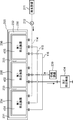
- first heat exchangers 431, 432, 433 and one second heat exchanger 434 are installed.
- the first heat exchangers 431, 432 and 433 are installed in the foundation structure 200 so as to be arranged in the installation areas 234, 235 and 236, respectively. That is, the first heat exchangers 431, 432 and 433 are installed at the positions where the existing heat exchangers 111, 112 and 113 were installed, respectively.
- the second heat exchanger 434 is installed at a position away from the foundation structure 200.
- connection step the first heat exchangers 431, 432 and 433 are connected to the three manifolds 114, 115 and 116, respectively.
- the manifold 116 is also connected to the second heat exchanger 434.
- the second heat exchanger 434 is connected to the demand destination, and the new vaporizer 400 is completed.
- the description of the open rack type vaporizer 300 of FIG. 2 is incorporated into each of the first heat exchangers 431, 432, 433.
- FIG. 6 is a schematic cross-sectional view of the heat exchanger 440.
- the heat exchanger 440 includes a hollow shell 441 from which the heating medium flows in and out, a plurality of heat transfer tubes 442 through which vaporized gas flows, and a pair of tube chambers 443 and 444 connected to both ends of each of these heat transfer tubes 442. have.
- the heat exchanger 440 has supply pipes 471 and discharge pipes 472 forming inlets and outlets for the heating medium with respect to the shell 441, respectively.
- the heat transfer tube 442 is arranged in the shell 441 and extends in the extending direction of the shell 441.
- the pipe chamber 443 is connected to the manifold 116 or the pipe member connected to the manifold 116 in the connecting step (see FIG. 5).
- the pipe chamber 444 is connected to a pipe member connected to a demand destination.
- the vaporized gas may be passed through the shell 441, and the heating medium may be passed through the heat transfer tube 442.
- the heating medium is a supply pipe after the heat exchanger 440 is installed as the second heat exchanger 434 or after the connection step is completed in the installation step (see FIG. 4) and the connection step (see FIG. 5). It is supplied into the shell 441 through 471.
- the heating medium gives heat to the vaporized gas flowing through the plurality of heat transfer tubes 442 in the shell 441.
- the heating medium is then discharged out of the shell 441 through the discharge pipe 472.
- the heating medium supplied into the shell 441 may be seawater or another medium having a temperature higher than that of the vaporized gas. When seawater is used as a heating medium, it may be supplied from the water intake facility 211 to the supply pipe 471.
- the liquefied gas is supplied from the supply facility 220 to the first heat exchangers 431, 432 and 433.
- the vaporized gas obtained as a result of the heat exchange in the first heat exchangers 431, 432 and 433 flows into the heat transfer tube 442 through the manifold 116 and the tube chamber 443.
- the vaporized gas flowing in the heat transfer tube 442 exchanges heat with the heating medium in the shell 441, and becomes a temperature exceeding the temperature required by the demand destination.
- the vaporized gas heated by the heating medium is discharged through the tube chamber 444 and supplied to the demand destination.
- ancillary facilities such as the foundation structure 200, manifolds 114, 115, 116, supply facility 220, seawater pump 212 and water intake facility 211 are used for both the vaporizers 100 and 400. I understand. Since these ancillary facilities can be used as they are for the new vaporizer 400, the increase in cost associated with the replacement of the existing vaporizer 100 with the new vaporizer 400 is suppressed. However, some or all of these ancillary equipment may be replaced to meet the performance requirements of the new vaporizer 400.
- the new vaporizer 400 has a second heat exchanger 434 in addition to the first heat exchangers 431, 432 and 433 corresponding to the existing heat exchangers 111, 112 and 113. Since the second heat exchanger 434 is responsible for raising the temperature of the vaporized gas generated by the first heat exchanger 431,432,433, the first heat exchanger 431,432,433 is an existing heat exchanger 111. , 112, 113, it does not have to take on the function of raising the temperature of the vaporized gas. If the new vaporizer 400 is required to supply more vaporized gas than the existing vaporizer 100, the supply facility 220 will supply more liquefied gas to the existing heat exchangers 111, 112, 113.
- the liquefied gas is supplied to the first heat exchangers 431, 432 and 433 according to the supply amount.
- the temperature of the vaporized gas from the first heat exchanger 431, 432, 433 to the second heat exchanger 434 may be lower than the temperature required by the demand destination.
- the second heat exchanger 434 raises the temperature of the vaporized gas, the temperature of the vaporized gas from the second heat exchanger 434 toward the demand destination can satisfy the required temperature of the demand destination. Therefore, the new vaporizer 400 has a high vaporization capacity and can supply a vaporized gas that meets the demands of the demanded party.
- the new vaporizer 400 when the new vaporizer 400 is required to supply the vaporized gas at a temperature higher than the temperature of the vaporized gas obtained from the existing vaporizer 100, it is vaporized by mainly controlling the second heat exchanger 434. The temperature of the gas can be raised to the required temperature condition of the demand destination. Even in this case, the new vaporizer 400 has a high vaporization capacity and can supply the vaporized gas that satisfies the demand of the demand destination.
- the new vaporizer 400 has the following advantages. Depending on the demands of the customer, the vaporizer 400 can be operated so as to obtain one of the following advantages.
- the new vaporizer 400 can improve the amount of liquefied gas processed as compared with the existing vaporizer 100. (2) The new vaporizer 400 can also raise the temperature of the obtained vaporized gas higher than that of the vaporizer 100. (3) The new vaporizer 400 can improve the processing amount of the liquefied gas as compared with the vaporizer 100 and raise the temperature of the obtained vaporized gas higher than that of the vaporizer 100.
- the vaporized gas obtained by the three first heat exchangers 431, 432 and 433 flows into the second heat exchanger 434. That is, the temperature rise treatment for the vaporized gas obtained by the three first heat exchangers 431, 432 and 433 is performed by one second heat exchanger 434. Therefore, the new vaporizer 400 does not require a large area as compared with the structure in which the temperature raising equipment is provided corresponding to each of these first heat exchangers 431, 432 and 433. Compared with the installation area of the existing vaporizer 100, the new vaporizer 400 requires only an area increased by the installation area of the second heat exchanger 434.
- the heating medium flowing in and out of the shell 441 can be selected from various types provided that the heating medium has a temperature higher than that of the vaporized gas flowing into the shell 441.
- the heating medium may be any of hot water, industrial water, seawater, steam and hot air.
- FIG. 7 is a schematic cross-sectional view of another heat exchanger 450 that can be used as the second heat exchanger 434.
- the heat exchanger 450 will be described with reference to FIGS. 1, 6 and 7.
- the heat exchanger 450 includes a heat transfer tube 453 having a plurality of fins 451. These fins 451 are provided to increase the heat transfer area from the air to the vaporized gas. While the vaporized gas is flowing through the heat transfer tube 453, the heat of the air is transferred to the vaporized gas through the heat transfer tube 453 and the fins 451. Since air is used to raise the temperature of the vaporized gas, the running cost of the heat exchanger 450 is relatively low.
- the second heat exchanger 434 may be a plate type heat exchanger.
- FIG. 8 is a schematic perspective view of a plate heat exchanger 460 that can be used as the second heat exchanger 434.
- the heat exchanger 460 has a plurality of heat transfer plates 461 having high thermal conductivity. These heat transfer plates 461 have irregularities formed on their surfaces and are stacked in a predetermined direction. As a result, a flow path through which the vaporized gas or the heating medium flows is formed at the boundary between the adjacent heat transfer plates 461.
- the joint between a pair of adjacent heat transfer plates 461 that form a flow path for vaporized gas is referred to as a "first joint 462" in the following description.
- the joint between a pair of adjacent heat transfer plates 461 that form a flow path for the heating medium is referred to as a "second joint 463" in the following description.
- the first joint portion 462 and the second joint portion 463 are alternately arranged in the alignment direction of the heat transfer plate 461.
- the heat exchanger 460 is formed with a supply flow path 464 and an exhaust flow path 465 for vaporized gas, and a supply flow path 466 and a discharge flow path 467 for a heating medium. These flow paths 464 to 467 are formed so as to penetrate each of the heat transfer plates 461.
- the supply flow path 464 and the exhaust flow path 465 for the vaporized gas are connected to the flow path formed at the first joint portion 462. Therefore, this flow path becomes a gas flow path through which the vaporized gas flows.
- the supply flow path 466 and the discharge flow path 467 for the heating medium are connected to the flow path formed in the second joint portion 463. Therefore, this flow path becomes a medium flow path through which the heating medium flows.
- connection step the manifold 116 or the pipe member extending from the manifold 116 is connected to the vaporized gas supply flow path 464.
- the pipe member connected to the demand destination is connected to the exhaust flow path 465 for vaporized gas.
- a pipe member that guides the heating medium discharged from the supply source (not shown) of the heating medium is connected to the supply flow path 466 for the heating medium.
- a pipe member that returns the heating medium to the supply source is connected to the discharge flow path 467 for the heating medium.
- liquefied gas is supplied from the supply facility 220 to the first heat exchangers 431, 432 and 433.
- the vaporized gas obtained by the first heat exchangers 431, 432 and 433 flows into the gas flow path of the first joint portion 462 through the supply flow path 464 for the vaporized gas.
- the heating medium is supplied from the supply source to the medium flow path of the second joint portion 463 through the supply flow path 466.
- the vaporized gas flowing in the gas flow path of the first joint portion 462 heats up with the heating medium flowing in the medium flow path of the second joint portion 463 via the heat transfer plate 461.
- the heated vaporized gas is supplied to the demand destination through the exhaust flow path 465.
- the heating medium after heat exchange is returned to the supply source through the discharge flow path 467.
- Heat exchange between the vaporized gas and the heating medium is performed via a plurality of heat transfer plates 461 having high thermal conductivity. Therefore, the heat of the heating medium is efficiently transferred to the vaporized gas.
- FIG. 9 is a schematic layout diagram of the existing vaporizer 101.
- FIG. 10 is a schematic layout diagram showing the removal process.
- FIG. 11 is a schematic layout diagram showing the installation process.
- FIG. 12 is a schematic layout diagram showing the connection process. A method of replacing the existing vaporizer 101 with the new vaporizer 401 will be described with reference to FIGS. 1, 3, 9 to 12.
- the existing vaporizer 101 has one heat exchanger 111.
- the heat exchanger 111 is installed in the foundation structure 201.
- the foundation structure 201 has a base portion 230 and a foundation frame 237.
- the base frame 237 has a substantially C-shaped shape in a plan view so as to form an installation area 234.
- the removal step see FIG. 10
- the connection between the heat exchanger 111, the seawater pump 212, the supply equipment 220 and the demand destination is disconnected.
- the heat exchanger 111 is removed from the foundation structure 201.
- the first heat exchanger 431 is installed in the foundation structure 201.
- the second heat exchanger 434 is installed outside the foundation structure 201.
- the connection step see FIG.
- the first heat exchanger 431 is connected to the seawater pump 212, the supply equipment 220 and the second heat exchanger 434.
- the second heat exchanger 434 is connected to the demand destination in addition to the first heat exchanger 431. After that, the amount of liquefied gas supplied from the supply facility 220 is increased.
- the new first heat exchangers 431, 432, 433 may have the same structure as the existing heat exchangers 111, 112, 113, or the existing heat exchangers 111, 112. , 113 may have an improved structure.
- the first heat exchanger 431,432,433 can be placed in the installation area 234,235,236, the first heat exchanger 431,432,433 is an existing heat exchanger. It may have more heat transfer tubes 313 than 111, 112, 113.
- the foundation frame 231 is open toward the manifolds 114, 115, 116.
- the base frame 231 may be opened in the direction opposite to the manifolds 114, 115, 116.
- At least one of the existing heat exchangers 111, 112, 113 shown in FIG. 1 has two or more open rack vaporizers 300 shown in FIG. 2, the basic structure 200 is the same.
- a partition member (not shown) belonging to the heat exchanger of the above and partitioning the open rack type vaporizers adjacent to each other may be further included.
- the types of liquefied gas supplied to the vaporizers 100 and 400 include liquefied natural gas.
- seawater is used for vaporizing liquefied gas.
- another heating liquid having a temperature higher than that of the liquefied gas may be used for vaporizing the liquefied gas.
- the method of replacing the vaporizer described in relation to the various embodiments described above mainly has the following features.
- the liquefied gas is vaporized to generate the vaporized gas by supplying the heating liquid to the outer peripheral surface of the heat transfer tube through which the liquefied gas is flowing. It can be used to replace an existing vaporizer with a heat exchanger that raises the temperature of the vaporized gas with a new vaporizer.
- the replacement method is to vaporize the liquefied gas by removing the heat exchanger of the existing vaporizer from the basic structure and supplying a heating liquid to the outer peripheral surface of the heat transfer tube through which the liquefied gas is flowing.
- a first heat exchanger equipped with one or more open rack heat exchangers configured to allow the heat exchanger to be installed on the basic structure from which the heat exchanger has been removed and obtained as a result of vaporization of the liquefied gas.
- a second heat exchanger for raising the temperature of the vaporized gas is installed in a place different from the basic structure, and the vaporized gas flows from the first heat exchanger into the second heat exchanger.
- the first heat exchanger is connected to the second heat exchanger, and the supply amount of the liquefied gas supplied to the first heat exchanger is supplied to the heat exchanger of the existing vaporizer.
- the new vaporizer can have a vaporization capacity higher than that of the existing vaporizer as follows, and the basic structure used for the installation of the existing vaporizer is newly vaporized. It will also be available for equipment.
- the basic structure for the existing vaporizer will be used to install the first heat exchanger of the new vaporizer.
- the vaporized gas vaporized in the first heat exchanger flows into the second heat exchanger and is heated by the second heat exchanger. That is, the second heat exchanger is responsible for raising the temperature of the vaporized gas obtained by the first heat exchanger.
- the first heat exchanger does not have to have a function of raising the temperature of the vaporized gas, and may cause a phase change from the liquefied gas to the vaporized gas. Since the temperature of the liquefied gas from the first heat exchanger to the second heat exchanger may be lower than the required temperature, the supply amount of the liquefied gas to the first heat exchanger is the existing vaporizer. The value can be set larger than the amount of liquefied gas supplied to the heat exchanger. Even when the customer needs a vaporized gas having a temperature higher than the temperature of the vaporized gas generated by the existing vaporizer, the second heat exchanger is used to vaporize the gas to meet the temperature requirement of the customer. It is possible to generate gas. Therefore, the new vaporizer has a vaporization capacity superior to that of the existing vaporizer.
- the foundation structure may include a foundation frame erected to define an installation area in which the heat exchanger of the existing vaporizer is installed.
- the first heat exchanger may be installed in the installation area.
- the foundation frame used for the existing vaporizer is also used for the new vaporizer. Since there is no need to install a new foundation frame, the cost for replacing the vaporizer is reduced.
- the existing vaporizer may have a plurality of the heat exchangers.
- the plurality of heat exchangers may be removed from the basic structure.
- the first heat exchanger may be installed at each of a plurality of installation positions where the plurality of heat exchangers have been installed.
- the step of connecting the first heat exchanger to the second heat exchanger (i) the first of the plurality of units so that the vaporized gas obtained in the plurality of first heat exchangers flows in.
- a manifold is connected to the heat exchanger, and (ii) the manifold or a tube member extending from the manifold is attached to the second heat exchanger so that the vaporized gas flowing into the manifold flows into the second heat exchanger. You may connect.
- the vaporizer that replaces the existing vaporizer is constructed without requiring an excessively large installation space as follows.
- the new vaporizer may have a plurality of first heat exchangers to be replaced by these heat exchangers. Since these first heat exchangers are arranged at the installation positions of the heat exchangers of the existing vaporizers, the space used for installing the plurality of heat exchangers of the existing vaporizers is the first of the plurality of units. 1 Can be used to install heat exchangers. Since these first heat exchangers are connected by a manifold, the vaporized gas obtained by these first heat exchangers flows into the manifold.
- the second heat exchanger can receive the vaporized gas obtained by the plurality of first heat exchangers through the manifold or the pipe member extending from the manifold, and can raise the temperature of the received vaporized gas. That is, the function of raising the temperature of the vaporized gas can be obtained without installing a plurality of second heat exchangers corresponding to each of the plurality of first heat exchangers. Since it is not necessary to install multiple second heat exchangers corresponding to each of the plurality of first heat exchangers, the vaporizer that replaces the existing vaporizer does not require an excessively large installation space. ..
- the second heat exchanger may be configured to raise the temperature of the vaporized gas by using a heating medium that is different in type from the heating liquid.
- the heating liquid used for vaporizing the liquefied gas is also used for raising the temperature of the vaporized gas.
- the heating medium cannot be selected depending on the vaporization of the liquefied gas and the temperature rise of the vaporized gas.
- the second heat exchanger is different from the heat exchanger of the existing vaporizer, and uses a heating medium different in type from the heating liquid used for the phase change from the liquefied gas to the vaporized gas. To raise the temperature. Therefore, a heating medium suitable for raising the temperature of the vaporized gas can be selected.
- the second heat exchanger has a hollow shell, a heat transfer tube extended in the shell, and a heating medium having a temperature higher than that of the vaporized gas so as to flow in and out of the shell. It may have a supply pipe and a discharge pipe connected to the shell.
- the first heat is such that the vaporized gas flows from the first heat exchanger into the heat transfer tube of the second heat exchanger.
- a tube member extending from the exchanger may be connected to the second heat exchanger.
- the heating medium can be selected from various types of media under the condition that the temperature is higher than that of the vaporized gas.
- the second heat exchanger may be a plate type heat exchanger in which a flow path for a heating medium having a temperature higher than that of the vaporization gas and a flow path for the vaporization gas are formed. ..
- the first heat exchanger is such that the vaporized gas flows from the first heat exchanger into the flow path for the vaporized gas.
- the tube member extending from may be connected to the plate type heat exchanger.
- the heat of the heating medium flowing through the medium flow path is transferred to the vaporized gas in the gas flow path through the heat transfer plate and used for raising the temperature of the vaporized gas.
- the second heat exchanger may have a heat transfer tube and fins protruding from the heat transfer tube.
- the first heat is such that the vaporized gas flows from the first heat exchanger into the heat transfer tube of the second heat exchanger.
- a tube member extending from the exchanger may be connected to the second heat exchanger.
- the vaporized gas flows from the first heat exchanger into the heat transfer tube of the second heat exchanger and exchanges heat with air through the heat transfer tube and fins, so that air is used to raise the temperature of the vaporized gas. Is available. Therefore, the cost required for raising the temperature of the vaporized gas is suppressed.
Landscapes
- Engineering & Computer Science (AREA)
- General Engineering & Computer Science (AREA)
- Mechanical Engineering (AREA)
- Physics & Mathematics (AREA)
- Thermal Sciences (AREA)
- Mining & Mineral Resources (AREA)
- Life Sciences & Earth Sciences (AREA)
- General Life Sciences & Earth Sciences (AREA)
- Geometry (AREA)
- Paleontology (AREA)
- Civil Engineering (AREA)
- Structural Engineering (AREA)
- Filling Or Discharging Of Gas Storage Vessels (AREA)
- Foundations (AREA)
- Heat-Exchange Devices With Radiators And Conduit Assemblies (AREA)
- Organic Low-Molecular-Weight Compounds And Preparation Thereof (AREA)
Abstract
本出願は、既存の気化装置を新たな気化装置に置き換える方法を開示する。置き換え方法は、既存の気化装置の熱交換器を、基礎構造から除去することと、オープンラック式気化器を備える第1熱交換器を、熱交換器が除去された基礎構造上に据え付けることと、液化ガスの気化の結果得られた気化ガスを昇温させる第2熱交換器を基礎構造とは別の場所に設置することと、気化ガスが第1熱交換器から第2熱交換器へ流入するように、第1熱交換器を第2熱交換器に接続することと、第1熱交換器に供給される液化ガスの供給量を、既存の気化装置の熱交換器へ供給されていた液化ガスの供給量よりも大きくすることと、を備えている。
Description
本発明は、既存の気化装置を新たな気化装置に置き換える方法に関する。
液化ガスが流れている伝熱管の外周面に加熱用液体を供給することによって、液化ガスを気化させるように構成された熱交換器を有しているオープンラック式の気化装置は既知である(特許文献1及び2を参照)。
既存の気化装置を新たな気化装置に交換するとき、交換に伴うコストの上昇を抑制しつつ、液化ガスを気化する能力を増加させることが要求されることがある。交換コストの上昇の抑制のためには、既存の気化装置の熱交換器の据え付けに利用されていた基礎構造が新たな気化装置にも利用されることが好ましい。しかしながら、基礎構造が再利用される場合には、新たな気化装置の能力を増大させることが困難なこともある。たとえば、基礎構造が再利用される場合には、新たな気化装置のサイズを既存の気化装置のサイズから大幅に増加させることはできない。新たな気化装置のサイズの増加が許容されないならば、たとえば、伝熱管の数を増やすことや、伝熱管を長くすることや、伝熱パネルの数を増やすことといった措置を採れず、気化能力が制限される。
本発明は、既存の気化装置の熱交換器の基礎構造を利用しながらも、既存の気化装置よりも優れた気化能力を有する新たな気化装置を据え付けることを可能にする技術を提供することを目的とする。
本発明の一の局面に係る気化装置の置き換え方法は、液化ガスが流れている伝熱管の外周面に加熱用液体を供給することによって、前記液化ガスを気化させて気化ガスを生成するとともに前記気化ガスを昇温する熱交換器を有している既存の気化装置を新たな気化装置に置き換えるために利用可能である。置き換え方法は、前記既存の気化装置の前記熱交換器を、基礎構造から除去することと、液化ガスが流れている伝熱管の外周面に加熱用液体を供給することによって、前記液化ガスを気化させるように構成された1又は2以上のオープンラック式気化器を備える第1熱交換器を、前記熱交換器が除去された前記基礎構造上に据え付けることと、前記液化ガスの気化の結果得られた気化ガスを昇温させる第2熱交換器を前記基礎構造とは別の場所に設置することと、前記気化ガスが前記第1熱交換器から前記第2熱交換器へ流入するように、前記第1熱交換器を前記第2熱交換器に接続することと、前記第1熱交換器に供給される前記液化ガスの供給量を、前記既存の気化装置の前記熱交換器へ供給されていた前記液化ガスの供給量よりも大きくすること、及び、前記液化ガスの気化の結果得られた気化ガスの温度を、前記既存の気化装置による気化の結果得られた気化ガスの温度よりも高くすることのうち少なくともいずれか一方を行うことと、を備えている。
上述の置き換え方法は、既存の気化装置の熱交換器の基礎構造を利用して既存の気化装置よりも優れた気化能力を有する新たな気化装置を据え付けることを可能にする。
本発明の目的、特徴及び利点は、以下の詳細な説明と添付図面とによって、より明白となる。
図1は、既存の気化装置100の概略的なレイアウト図である。図1を参照して、既存の気化装置100が説明される。
気化装置100は、基礎構造200上で間隔を空けて整列された3基の熱交換器111,112,113と、これらの熱交換器111,112,113に接続された3つのマニホールド114,115,116とを備えている。熱交換器111,112,113それぞれは、海水と液化ガスとの間の熱交換を通じて液化ガスを気化させ、気化ガスを生成するために設置されている。マニホールド114,115,116は、これらの熱交換器111,112,113への海水及び液化ガスの供給並びにこれらの熱交換器111,112,113からの気化ガスの回収に用いられる。
マニホールド114,115,116は、基礎構造200の外側で熱交換器111,112,113の整列方向に延設されている。マニホールド114,115,116それぞれは、熱交換器111,112,113に接続されている。マニホールド114は、取水設備211によって取水された海水を吐出する海水ポンプ212に接続されている。海水の供給経路は、図1において、点線で描かれている。マニホールド115は、液化ガスを供給する供給設備220に接続されている。供給設備220からの液化ガスの供給量は、需要先が必要としている気化ガスの量に基づいて、所定の値に設定されている。液化ガスの供給経路は、図1において、鎖線で描かれている。マニホールド116には、熱交換器111,112,113で生成された気化ガスが流入する。マニホールド116は、気化ガスを必要としている需要先から延設された管部材に接続されている。気化ガスの流動経路は、図1において、実線で描かれている。
基礎構造200は、熱交換器111,112,113を固定するために用いられる。基礎構造200は、地面上に形成されたベース部230と、ベース部230から立設された基礎枠231とを含んでいる。基礎枠231は、平面視において、略C型に形成された外枠232と、外枠232によって囲まれた領域を3つの据付領域234,235,236に仕切る2つの仕切枠233とを含んでいる。
熱交換器111,112,113は、オープンラック式の構造を有しており、構造的に共通している。熱交換器111,112,113の構造が、図1及び図2を参照して説明される。図2は、熱交換器111,112,113それぞれに含まれるオープンラック式気化器300の概略的な斜視図である。熱交換器111,112,113は、それぞれ、オープンラック式気化器300を1つのみ有していてもよいし、オープンラック式気化器300を2以上有していてもよい。
オープンラック式気化器300は、所定流量の液化ガスが供給設備220から供給されたときに、需要先が必要としている温度を上回る温度の気化ガスを生成するように構成されている。オープンラック式気化器300は、3つの伝熱パネル310と、マニホールド114から直接的又は間接的に延設された4つの供給管321と、これらの供給管321にそれぞれ接続された4つのトラフ322とを含んでいる。加えて、オープンラック式気化器300は、一対のマニホールド315,316を有している。マニホールド315は、図1を参照して説明されたマニホールド115に接続されている(図1を参照)。マニホールド316は、図1を参照して説明されたマニホールド116に接続されている。4つのトラフ322は、間隔を空けて、基礎枠231の 開口部位の幅方向に整列されている。伝熱パネル310は、トラフ322の間で立設されている。したがって、3つの伝熱パネル310も、間隔を空けて、基礎枠231の 開口部位の幅方向に整列されている。
3つの伝熱パネル310それぞれは、下ヘッダ管311と、下ヘッダ管311の上方に離間した位置に配置された上ヘッダ管312と、下ヘッダ管311と上ヘッダ管312との間で略鉛直に延びる複数の伝熱管313とを含んでいる。下ヘッダ管311は、液化ガス用のマニホールド315から延び、据付領域234,235,236内に入り込んでいる。上ヘッダ管312は、気化ガス用のマニホールド316から延び、据付領域234,235,236内に入り込んでいる。複数の伝熱管313は、下ヘッダ管311及び上ヘッダ管312の延設方向に整列されている。
4つのトラフ322それぞれは、対応する伝熱パネル310に海水を供給するために用いられる。トラフ322及び対応する伝熱パネル310は、オープンラック式の気化器を形成している。トラフ322は、伝熱管313の整列方向に長い箱状の構造を有し、上方に開口している。トラフ322は、上ヘッダ管312よりも低い位置且つ鉛直方向における伝熱パネル310の中間位置よりも高い位置に配置され、複数の伝熱管313の上部に隣り合っている。
4つの供給管321は、4つのトラフ322と海水用のマニホールド114とに接続され、海水の供給経路を形成している。
海水は、取水設備211によって取水された後、海水ポンプ212によってマニホールド114へ送り出される。海水は、マニホールド114によって、熱交換器111,112,113それぞれの4つの供給管321に分配される。海水は、これらの供給管321を通じて、熱交換器111,112,113それぞれの4つのトラフ322に供給される。海水は、トラフ322から溢れ、複数の伝熱管313の外周面の上部に供給される。海水は、これらの伝熱管313の外周面に沿って流下する。海水の供給量は、需要先が必要としている温度を上回る温度の気化ガスが得られるように設定されている。
液化ガスは、供給設備220からマニホールド115,315に供給され、マニホールド315によって、熱交換器111,112,113それぞれの下ヘッダ管311に分配される。液化ガスは、下ヘッダ管311から複数の伝熱管313に流入し、上ヘッダ管312に向かう。この間、液化ガスは、複数の伝熱管313の外周面に沿って流下している海水と熱交換し、気化ガスになる。気化ガスは、上ヘッダ管312及びマニホールド316,116を順次通過し、需要先に供給される。熱交換器111,112,113は、液化ガスから気化ガスへの相変化を生じさせる役割だけではなく、気化ガスをある程度昇温する役割を有している。したがって、熱交換器111,112,113から排出される気化ガスの温度は、需要先が必要としている所定の温度を超えている。
気化装置100を新たな気化装置400に置き換えるための置き換え方法が、図1、図3乃至図5を参照して説明される。置き換え方法は、気化装置100を除去する除去工程と、新たな気化装置400の主要部位を据え付ける据付工程と、主要部位間の管接続を行う接続工程とに大別される。図3は、除去工程を概略的に表すレイアウト図である。図4は、据付工程を概略的に表すレイアウト図である。図5は、接続工程を概略的に表すレイアウト図である。
除去工程(図3を参照)において、マニホールド114,115,116と熱交換器111,112,113との間の接続が解除される。その後、熱交換器111,112,113が、基礎構造200から撤去される。
据付工程(図4を参照)において、3基の第1熱交換器431,432,433及び1基の第2熱交換器434が設置される。第1熱交換器431,432,433は、据付領域234,235,236内にそれぞれ配置されるように、基礎構造200に据え付けられる。すなわち、第1熱交換器431,432,433は、既存の熱交換器111,112,113が据え付けられていた位置にそれぞれ据え付けられる。第2熱交換器434は、基礎構造200から離れた位置に据え付けられる。
接続工程(図5を参照)において、第1熱交換器431,432,433は、3つのマニホールド114,115,116それぞれに連結される。マニホールド116は、第2熱交換器434にも連結される。接続工程において、第2熱交換器434が需要先に繋げられ、新たな気化装置400が完成する。
第1熱交換器431,432,433の構成に関して、図2のオープンラック式気化器300の説明が、第1熱交換器431,432,433それぞれに援用される。
第2熱交換器434として、シェルアンドチューブ構造を有している熱交換器440が利用可能である。熱交換器440が、図4乃至図6を参照して説明される。図6は、熱交換器440の概略的な断面図である。
熱交換器440は、加熱用媒体が流入出する中空のシェル441と、気化ガスが流れる複数の伝熱管442と、これらの伝熱管442それぞれの両端に接続された一対の管室443,444とを有している。加えて、熱交換器440は、シェル441に対する加熱用媒体の流入口及び流出口をそれぞれ形成している供給管471及び排出管472を有している。伝熱管442は、シェル441内に配設され、シェル441の延設方向に延びている。管室443は、接続工程(図5を参照)において、マニホールド116又はマニホールド116 に接続された管部材に連結される。管室444は、需要先に繋がる管部材に連結される。なお、シェル441に気化ガスを流し、伝熱管442に加熱用媒体を流してもよい。
加熱用媒体は、据付工程(図4を参照)及び接続工程(図5を参照)において、熱交換器440が、第2熱交換器434として据え付けられた後又は接続工程の完了後に、供給管471を通じて、シェル441内に供給される。加熱用媒体は、シェル441内で複数の伝熱管442を流れる気化ガスに熱を与える。その後、加熱用媒体は、排出管472を通じて、シェル441の外に排出される。シェル441内に供給される加熱用媒体は、海水であってもよいし、気化ガスよりも高温の他の媒体であってもよい。海水が、加熱用媒体として用いられる場合には、取水設備211から供給管471に供給されてもよい。
新たな気化装置400が完成した後、液化ガスが供給設備220から第1熱交換器431,432,433へ供給される。第1熱交換器431,432,433での熱交換の結果得られた気化ガスが、マニホールド116及び管室443を通じて、伝熱管442へ流入する。伝熱管442内を流れる気化ガスは、シェル441内の加熱用媒体と熱交換し、需要先が必要としている温度を超える温度になる。加熱用媒体によって昇温された気化ガスは、管室444を通じて排出され、需要先へ供給される。
既存の気化装置100から新たな気化装置400への置き換えの利点が、以下に説明される。
図1及び図5を参照すると、基礎構造200、マニホールド114,115,116、供給設備220、海水ポンプ212及び取水設備211といった付帯設備は、気化装置100,400の両方に利用されていることが分かる。これらの付帯設備は、新たな気化装置400にそのまま利用可能であるので、既存の気化装置100から新たな気化装置400への置き換えに伴う費用の増加が抑制される。しかしながら、これらの付帯設備の一部又は全部は、新たな気化装置400に要求される性能に合わせて交換されてもよい。
新たな気化装置400は、既存の熱交換器111,112,113に対応する第1熱交換器431,432,433に加えて、第2熱交換器434を有している。第2熱交換器434は、第1熱交換器431,432,433で生成された気化ガスの昇温機能を担うので、第1熱交換器431,432,433は、既存の熱交換器111,112,113とは異なり、気化ガスに対する昇温機能を担わなくてもよい。既存の気化装置100よりも多くの気化ガスの供給が新たな気化装置400に要求された場合、供給設備220は、既存の熱交換器111,112,113への液化ガスの供給量よりも多い供給量で、液化ガスを第1熱交換器431,432,433に供給する。この場合、第1熱交換器431,432,433から第2熱交換器434へ向かう気化ガスの温度は、需要先が必要としている温度を下回ることがある。しかしながら、第2熱交換器434が気化ガスを昇温するので、第2熱交換器434から需要先に向かう気化ガスの温度は、需要先の要求温度条件を満たすことができる。したがって、新たな気化装置400は、高い気化能力を有し、需要先の要求を満たす気化ガスを供給することができる。
また、既存の気化装置100から得られる気化ガスの温度よりも高い温度の気化ガスの供給が新たな気化装置400に要求された場合、第2熱交換器434を主に制御することによって、気化ガスの温度を需要先の要求温度条件まで上げることができる。この場合でも、新たな気化装置400は、高い気化能力を有し、需要先の要求を満たす気化ガスを供給することができる。
上述の如く、新たな気化装置400は、以下の利点を有している。需要先の要求に応じて、以下の利点のうちいずれかが得られるように、気化装置400は操作され得る。
(1)新たな気化装置400は、液化ガスの処理量を既存の気化装置100よりも向上させることができる。
(2)新たな気化装置400は、得られる気化ガスの温度を気化装置100よりも高くすることもできる。
(3)新たな気化装置400は、液化ガスの処理量を気化装置100よりも向上させ、かつ、得られる気化ガスの温度を気化装置100よりも高くすることもできる。
(2)新たな気化装置400は、得られる気化ガスの温度を気化装置100よりも高くすることもできる。
(3)新たな気化装置400は、液化ガスの処理量を気化装置100よりも向上させ、かつ、得られる気化ガスの温度を気化装置100よりも高くすることもできる。
第2熱交換器434には、3基の第1熱交換器431,432,433で得られた気化ガスが流入する。すなわち、3基の第1熱交換器431,432,433で得られた気化ガスに対する昇温処理は、1基の第2熱交換器434によって行われる。したがって、これらの第1熱交換器431,432,433それぞれに対応して昇温設備を設ける構造と較べて、新たな気化装置400は、広い面積を必要としない。既存の気化装置100の設置領域と較べて、新たな気化装置400は、第2熱交換器434の設置領域分だけ増大した面積しか必要としていない。
シェル441内に流入出する加熱用媒体は、加熱用媒体がシェル441に流入する気化ガスより高い温度を有することを条件として、様々な種類から選択され得る。たとえば、加熱用媒体は、温水、工水、海水、スチーム及び温空気のいずれかであってもよい。
図7は、第2熱交換器434として利用可能な他の熱交換器450の概略的な断面図である。図1、図6及び図7を参照して、熱交換器450が説明される。
熱交換器450は、複数のフィン451を有した伝熱管453を備えている。これらのフィン451は、空気から気化ガスへの伝熱面積を増大させるために設けられている。気化ガスが、伝熱管453内を流れている間、空気の熱は、伝熱管453及びフィン451を通じて気化ガスへ伝達される。気化ガスの昇温に空気が用いられるので、熱交換器450のランニングコストは比較的廉価である。
第2熱交換器434は、プレート式の熱交換器であってもよい。図8は、第2熱交換器434として利用可能なプレート式の熱交換器460の概略的な斜視図である。
熱交換器460は、高い熱伝導率を有している複数の伝熱板461を有している。これらの伝熱板461は、表面に凹凸が形成されており、所定の方向に重ねられている。この結果、隣り合う伝熱板461の間に気化ガス又は加熱用媒体が流れる流路が境界に形成される。気化ガス用の流路を形成している隣り合う一対の伝熱板461同士の接合部は、以下の説明において、「第1接合部462」と称される。加熱用媒体用の流路を形成している隣り合う一対の伝熱板461同士の接合部は、以下の説明において、「第2接合部463」と称される。第1接合部462及び第2接合部463は、伝熱板461の整列方向において交互に並んでいる。
熱交換器460には、気化ガス用の供給流路464及び排気流路465並びに加熱用媒体用の供給流路466及び排出流路467が形成されている。これらの流路464~467は、伝熱板461それぞれを貫通するように形成されている。気化ガス用の供給流路464及び排気流路465は、第1接合部462において形成された流路に繋がっている。したがって、この流路は、気化ガスが流れるガス流路になる。加熱用媒体用の供給流路466及び排出流路467は、第2接合部463において形成された流路に繋がっている。したがって、この流路は、加熱用媒体が流れる媒体流路になる。
接続工程(図5を参照)において、マニホールド116又はマニホールド116から延びる管部材が気化ガス用の供給流路464に繋げられる。需要先に繋がる管部材が、気化ガス用の排気流路465に繋げられる。加熱用媒体用の供給流路466には、加熱用媒体の供給源(図示せず)から排出された加熱用媒体を案内する管部材が繋げられる。加熱用媒体用の排出流路467には、加熱用媒体を供給源に戻す管部材が繋げられる。
接続工程の後に、液化ガスが供給設備220から第1熱交換器431,432,433へ供給される。第1熱交換器431,432,433で得られた気化ガスは、気化ガス用の供給流路464を通じて、第1接合部462のガス流路に流入する。このとき、加熱用媒体が、供給流路466を通じて、供給源から第2接合部463の媒体流路へ供給される。第1接合部462のガス流路内を流れる気化ガスは、伝熱板461を介して、第2接合部463の媒体流路内を流れる加熱用媒体と熱交換し昇温される。昇温された気化ガスは、排気流路465を通じて、需要先へ供給される。熱交換後の加熱用媒体は、排出流路467を通じて、供給源に戻される。
気化ガスと加熱用媒体との間の熱交換は、高い熱伝導率を有している複数の伝熱板461を介して行われる。したがって、加熱用媒体の熱は、気化ガスへ効率的に伝達される。
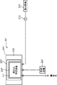
上述の実施形態に関して、複数基の熱交換器111,112,113を有している既存の気化装置100が新たな気化装置400に置き換えられている。しかしながら、上述の置き換え方法は、1基の熱交換器を有している既存の気化装置101から新たな気化装置401への置き換えにも適用可能である。図9は、既存の気化装置101の概略的なレイアウト図である。図10は、除去工程を表す概略的なレイアウト図である。図11は、据付工程を表す概略的なレイアウト図である。図12は、接続工程を表す概略的なレイアウト図である。図1、図3、図9乃至図12を参照して、既存の気化装置101から新たな気化装置401への置き換え方法が説明される。
既存の気化装置101(図9を参照)は、1基の熱交換器111を有している。熱交換器111は、基礎構造201に据え付けられている。基礎構造201は、ベース部230と基礎枠237とを有している。基礎枠237は、据付領域234を形成するように、平面視において略C型の形状を有している。除去工程(図10を参照)において、熱交換器111、海水ポンプ212、供給設備220及び需要先の間の接続が解除される。その後、熱交換器111は、基礎構造201から撤去される。据付工程(図11を参照)において、第1熱交換器431が基礎構造201に据え付けられる。第2熱交換器434が、基礎構造201の外で据え付けられる。接続工程(図12を参照)において、第1熱交換器431は、海水ポンプ212、供給設備220及び第2熱交換器434に接続される。第2熱交換器434は、第1熱交換器431に加えて、需要先に接続される。その後、供給設備220からの液化ガスの供給量が増やされる。
上述の実施形態に関して、新たな第1熱交換器431,432,433は、既存の熱交換器111,112,113と同じ構造を有していてもよいし、既存の熱交換器111,112,113が改良された構造を有していてもよい。たとえば、新たな第1熱交換器431,432,433を、据付領域234,235,236内に配置することができるならば、第1熱交換器431,432,433は、既存の熱交換器111,112,113よりも多くの伝熱管313を有していてもよい。
上述の実施形態に関して、基礎枠231は、マニホールド114,115,116に向けて開口している。しかしながら、基礎枠231は、マニホールド114,115,116とは反対向きに開口していてもよい。
図1に示されている既存の熱交換器111,112,113のうち少なくともいずれか1つが、図2に示されているオープンラック式気化器300を2以上有する場合、基礎構造200は、同一の熱交換器に属しかつ互いに隣り合うオープンラック式の気化器を仕切る仕切部材(図示せず)を、さらに含んでいてもよい。
気化装置100,400に供給される液化ガスの種類には、液化天然ガスが含まれる。
上述の実施形態に関して、液化ガスの気化に海水が利用されている。しかしながら、液化ガスよりも高い温度の他の加熱用液体が、液化ガスの気化に利用されてもよい。
上述の様々な実施形態に関連して説明された気化装置の置き換え方法は、以下の特徴を主に備えている。
本発明の一の局面に係る気化装置の置き換え方法は、液化ガスが流れている伝熱管の外周面に加熱用液体を供給することによって、前記液化ガスを気化させて気化ガスを生成するとともに前記気化ガスを昇温する熱交換器を有している既存の気化装置を新たな気化装置に置き換えるために利用可能である。置き換え方法は、前記既存の気化装置の前記熱交換器を、基礎構造から除去することと、液化ガスが流れている伝熱管の外周面に加熱用液体を供給することによって、前記液化ガスを気化させるように構成された1又は2以上のオープンラック式気化器を備える第1熱交換器を、前記熱交換器が除去された前記基礎構造上に据え付けることと、前記液化ガスの気化の結果得られた気化ガスを昇温させる第2熱交換器を前記基礎構造とは別の場所に設置することと、前記気化ガスが前記第1熱交換器から前記第2熱交換器へ流入するように、前記第1熱交換器を前記第2熱交換器に接続することと、前記第1熱交換器に供給される前記液化ガスの供給量を、前記既存の気化装置の前記熱交換器へ供給されていた前記液化ガスの供給量よりも大きくすること、及び、前記液化ガスの気化の結果得られた気化ガスの温度を、前記既存の気化装置による気化の結果得られた気化ガスの温度よりも高くすることのうち少なくともいずれか一方を行うことと、を備えている。
上記の構成によれば、新たな気化装置は、以下の如く、既存の気化装置を上回る気化能力を有することができるとともに、既存の気化装置の据え付けに用いられていた基礎構造が、新たな気化装置にも利用可能となる。既存の気化装置用の基礎構造は、新たな気化装置の第1熱交換器の据え付けに利用される。第1熱交換器で気化された気化ガスは、第2熱交換器に流入し、第2熱交換器によって昇温される。すなわち、第2熱交換器は、第1熱交換器で得られた気化ガスの昇温機能を担う。第1熱交換器は、既存の気化装置の熱交換器とは異なり、気化ガスに対する昇温機能を有さなくてもよく、液化ガスから気化ガスへの相変化を生じさせればよい。第1熱交換器から第2熱交換器へ向かう液化ガスの温度が、必要とされる温度を下回っていてもよいので、第1熱交換器への液化ガスの供給量は、既存の気化装置の熱交換器への液化ガスの供給量よりも大きな値に設定可能である。需要先が、既存の気化装置によって生成されていた気化ガスの温度よりも高い温度の気化ガスを必要としている場合にも、第2熱交換器を用いて、需要先の温度に対する要求を満たす気化ガスを生成することが可能である。したがって、新たな気化装置は、既存の気化装置を上回る気化能力を有する。
上記の構成に関して、前記基礎構造は、前記既存の気化装置の前記熱交換器が据え付けられる据付領域を定めるように立設された基礎枠を含んでもよい。前記据付領域内で前記第1熱交換器が据え付けられてもよい。
上記の構成によれば、第1熱交換器が、基礎枠によって定められた据付領域内で据え付けられるので、既存の気化装置に用いられていた基礎枠が新たな気化装置にも利用される。新たな基礎枠を設置する必要がないので、気化装置の置き換えのための費用が抑制される。
上記の構成に関して、前記既存の気化装置は、前記熱交換器を複数基有していてもよい。前記既存の気化装置の前記熱交換器を前記基礎構造から除去する工程において、前記複数基の熱交換器を前記基礎構造から除去してもよい。前記第1熱交換器を前記基礎構造上に据え付ける工程において、前記複数基の熱交換器が据え付けられていた複数の据付位置それぞれに、前記第1熱交換器を据え付けてもよい。前記第1熱交換器を前記第2熱交換器に接続する工程において、(i)前記複数基の第1熱交換器内で得られた前記気化ガスが流入するように前記複数基の第1熱交換器にマニホールドを接続し、(ii)前記マニホールドに流入した前記気化ガスが前記第2熱交換器に流入するように、前記マニホールド又は前記マニホールドから延びる管部材を前記第2熱交換器に接続してもよい。
上記の構成によれば、既存の気化装置と置き換えられた気化装置は、以下の如く、過度に広い設置スペースを要することなく構築される。既存の気化装置が、複数基の熱交換器を有しているとき、新たな気化装置は、これらの熱交換器に置き換えられる複数基の第1熱交換器を有してもよい。これらの第1熱交換器は、既存の気化装置の熱交換器の据付位置に配置されるので、既存の気化装置の複数基の熱交換器の設置に利用されたスペースが、複数基の第1熱交換器の設置に利用可能である。これらの第1熱交換器は、マニホールドによって接続されるので、これらの第1熱交換器で得られた気化ガスは、マニホールドに流入する。第2熱交換器は、マニホールド又はマニホールドから延びる管部材を通じて、複数基の第1熱交換器で得られた気化ガスを受け取り、受け取った気化ガスを昇温することができる。すなわち、複数基の第1熱交換器それぞれに対応して複数基の第2熱交換器を設置することなく、気化ガスに対する昇温機能が得られる。複数基の第1熱交換器それぞれに対応して複数基の第2熱交換器を設置する必要がないので、既存の気化装置と置き換えられた気化装置は、過度に広い設置スペースを必要としない。
上記の構成に関して、前記第2熱交換器は、前記加熱用液体とは種類において異なる加熱用媒体を用いて、前記気化ガスを昇温するように構成されていてもよい。
上記の構成によれば、既存の気化装置の熱交換器では、液化ガスの気化に用いられている加熱用液体が、気化ガスの昇温にも利用される。この場合、加熱用媒体を、液化ガスの気化と気化ガスの昇温とで選択できない。一方、第2熱交換器は、既存の気化装置の熱交換器とは異なり、液化ガスから気化ガスへの相変化に用いられる加熱用液体とは種類において異なる加熱用媒体を用いて、気化ガスを昇温する。したがって、気化ガスの昇温に適した加熱用媒体が選択可能である。
上記の構成に関して、前記第2熱交換器は、中空のシェルと、前記シェル内で延出された伝熱管と、前記気化ガスよりも高温の加熱用媒体が前記シェルに流入出するように、前記シェルに接続された供給管及び排出管とを有していてもよい。前記第1熱交換器を前記第2熱交換器に接続する工程において、前記気化ガスが前記第1熱交換器から前記第2熱交換器の前記伝熱管に流入するように、前記第1熱交換器から延びる管部材を前記第2熱交換器に接続してもよい。
上記の構成によれば、加熱用媒体は、気化ガスよりも高温であるという条件の下で、様々な種類の媒体から選択可能である。気化ガスが、第1熱交換器から第2熱交換器のシェル内で延出された伝熱管に流入すると、シェルに流入する加熱用媒体によって気化ガスが昇温される。
上記の構成に関して、前記第2熱交換器は、前記気化ガスよりも高温の加熱用媒体用の流路及び前記気化ガス用の流路が形成されたプレート式の熱交換器であってもよい。前記第1熱交換器を前記第2熱交換器に接続する工程において、前記気化ガスが前記第1熱交換器から前記気化ガス用の前記流路に流入するように、前記第1熱交換器から延びる管部材を前記プレート式の熱交換器に接続してもよい。
上記の構成によれば、媒体流路を流れる加熱用媒体の熱は、伝熱板を通じて、ガス流路中の気化ガスに伝達され、気化ガスの昇温に用いられる。
上記の構成に関して、前記第2熱交換器は、伝熱管と前記伝熱管から突出したフィンとを有していてもよい。前記第1熱交換器を前記第2熱交換器に接続する工程において、前記気化ガスが前記第1熱交換器から前記第2熱交換器の前記伝熱管に流入するように、前記第1熱交換器から延びる管部材を前記第2熱交換器に接続してもよい。
上記の構成によれば、気化ガスは、第1熱交換器から第2熱交換器の伝熱管に流入し、伝熱管及びフィンを介して空気と熱交換するので、気化ガスの昇温に空気が利用可能である。したがって、気化ガスの昇温に必要とされるコストが抑制される。
上述の実施形態に関連して説明された技術は、気化ガスを利用する様々な技術分野に好適に利用される。
Claims (7)
- 液化ガスが流れている伝熱管の外周面に加熱用液体を供給することによって、前記液化ガスを気化させて気化ガスを生成するとともに前記気化ガスを昇温する熱交換器を有している既存の気化装置を新たな気化装置に置き換える方法であって、
前記既存の気化装置の前記熱交換器を、基礎構造から除去することと、
液化ガスが流れている伝熱管の外周面に加熱用液体を供給することによって、前記液化ガスを気化させるように構成された1又は2以上のオープンラック式気化器を備える第1熱交換器を、前記熱交換器が除去された前記基礎構造上に据え付けることと、
前記液化ガスの気化の結果得られた気化ガスを昇温させる第2熱交換器を前記基礎構造とは別の場所に設置することと、
前記気化ガスが前記第1熱交換器から前記第2熱交換器へ流入するように、前記第1熱交換器を前記第2熱交換器に接続することと、
前記第1熱交換器に供給される前記液化ガスの供給量を、前記既存の気化装置の前記熱交換器へ供給されていた前記液化ガスの供給量よりも大きくすること、及び、前記液化ガスの気化の結果得られた気化ガスの温度を、前記既存の気化装置による気化の結果得られた気化ガスの温度よりも高くすることのうち少なくともいずれか一方を行うことと、を備えている
気化装置の置き換え方法。 - 前記基礎構造は、前記既存の気化装置の前記熱交換器が据え付けられる据付領域を定めるように立設された基礎枠を含み、
前記据付領域内で前記第1熱交換器を据え付ける
請求項1に記載の置き換え方法。 - 前記既存の気化装置は、前記熱交換器を複数基有しており、
前記既存の気化装置の前記熱交換器を前記基礎構造から除去する工程において、前記複数基の熱交換器を前記基礎構造から除去し、
前記第1熱交換器を前記基礎構造上に据え付ける工程において、前記複数基の熱交換器が据え付けられていた複数の据付位置それぞれに、前記第1熱交換器を据え付け、
前記第1熱交換器を前記第2熱交換器に接続する工程において、
(i)前記複数基の第1熱交換器内で得られた前記気化ガスが流入するように前記複数基の第1熱交換器にマニホールドを接続し、
(ii)前記マニホールドに流入した前記気化ガスが前記第2熱交換器に流入するように、前記マニホールド又は前記マニホールドから延びる管部材を前記第2熱交換器に接続する
請求項1又は2に記載の置き換え方法。 - 前記第2熱交換器は、前記加熱用液体とは種類において異なる加熱用媒体を用いて、前記気化ガスを昇温するように構成されている
請求項1又は2に記載の置き換え方法。 - 前記第2熱交換器は、中空のシェルと、前記シェル内で延出された伝熱管と、前記気化ガスよりも高温の加熱用媒体が前記シェルに流入出するように、前記シェルに接続された供給管及び排出管とを有し、
前記第1熱交換器を前記第2熱交換器に接続する工程において、前記気化ガスが前記第1熱交換器から前記第2熱交換器の前記伝熱管に流入するように、前記第1熱交換器から延びる管部材を前記第2熱交換器に接続する
請求項1又は2に記載の置き換え方法。 - 前記第2熱交換器は、前記気化ガスよりも高温の加熱用媒体用の流路及び前記気化ガス用の流路が形成されたプレート式の熱交換器であり、
前記第1熱交換器を前記第2熱交換器に接続する工程において、前記気化ガスが前記第1熱交換器から前記気化ガス用の前記流路に流入するように、前記第1熱交換器から延びる管部材を前記プレート式の熱交換器に接続する
請求項1又は2に記載の置き換え方法。 - 前記第2熱交換器は、伝熱管と前記伝熱管から突出したフィンとを有し、
前記第1熱交換器を前記第2熱交換器に接続する工程において、前記気化ガスが前記第1熱交換器から前記第2熱交換器の前記伝熱管に流入するように、前記第1熱交換器から延びる管部材を前記第2熱交換器に接続する
請求項1又は2に記載の置き換え方法。
Applications Claiming Priority (2)
| Application Number | Priority Date | Filing Date | Title |
|---|---|---|---|
| JP2019076335A JP6741820B1 (ja) | 2019-04-12 | 2019-04-12 | 気化装置の置き換え方法 |
| JP2019-076335 | 2019-04-12 |
Publications (1)
| Publication Number | Publication Date |
|---|---|
| WO2020209203A1 true WO2020209203A1 (ja) | 2020-10-15 |
Family
ID=72047973
Family Applications (1)
| Application Number | Title | Priority Date | Filing Date |
|---|---|---|---|
| PCT/JP2020/015371 Ceased WO2020209203A1 (ja) | 2019-04-12 | 2020-04-03 | 気化装置の置き換え方法 |
Country Status (3)
| Country | Link |
|---|---|
| JP (1) | JP6741820B1 (ja) |
| TW (1) | TWI768318B (ja) |
| WO (1) | WO2020209203A1 (ja) |
Families Citing this family (1)
| Publication number | Priority date | Publication date | Assignee | Title |
|---|---|---|---|---|
| JP2025149405A (ja) * | 2024-03-26 | 2025-10-08 | 川崎重工業株式会社 | 極低温用圧縮設備、及びそれを備えるボイルオフガス液化システム |
Citations (6)
| Publication number | Priority date | Publication date | Assignee | Title |
|---|---|---|---|---|
| US4738309A (en) * | 1984-09-13 | 1988-04-19 | Heinz Schilling Kg | Gas/liquid or gas/gas exchanger |
| JPH10196894A (ja) * | 1996-12-27 | 1998-07-31 | Tokyo Gas Co Ltd | 液化天然ガス熱量調整装置 |
| JP2003014194A (ja) * | 2001-07-02 | 2003-01-15 | Kobe Steel Ltd | 気化装置ユニット及び気化装置の施工方法 |
| JP2018162917A (ja) * | 2017-03-24 | 2018-10-18 | 日新製鋼株式会社 | ガス予熱装置の操業方法 |
| JP2019007205A (ja) * | 2017-06-23 | 2019-01-17 | 三菱重工業株式会社 | 容器の補強方法及び容器の支持構造 |
| JP2019027086A (ja) * | 2017-07-27 | 2019-02-21 | 三菱重工業株式会社 | 容器の補強方法及び容器の支持構造 |
Family Cites Families (6)
| Publication number | Priority date | Publication date | Assignee | Title |
|---|---|---|---|---|
| JP3547169B2 (ja) * | 1994-05-30 | 2004-07-28 | 株式会社荏原製作所 | 液化ガス供給設備 |
| KR100888394B1 (ko) * | 2007-07-05 | 2009-03-13 | 한국가스공사 | Lng 기화 시스템의 증설 최적화 방법 |
| JP6448409B2 (ja) * | 2015-02-25 | 2019-01-09 | 住友精密工業株式会社 | オープンラック式気化器の伝熱管交換方法及び当該交換方法に用いる伝熱管 |
| JP6420223B2 (ja) * | 2015-10-14 | 2018-11-07 | 株式会社神戸製鋼所 | ガス気化器 |
| CN106382463A (zh) * | 2016-11-29 | 2017-02-08 | 中国海洋石油总公司 | 一种lng接收站冷量置换及梯级利用的工艺方法及装置 |
| CN207729246U (zh) * | 2017-07-11 | 2018-08-14 | 乐山市山鹰模具有限责任公司 | Bog、eag空温式气化供气装置 |
-
2019
- 2019-04-12 JP JP2019076335A patent/JP6741820B1/ja active Active
-
2020
- 2020-04-03 WO PCT/JP2020/015371 patent/WO2020209203A1/ja not_active Ceased
- 2020-04-09 TW TW109111929A patent/TWI768318B/zh active
Patent Citations (6)
| Publication number | Priority date | Publication date | Assignee | Title |
|---|---|---|---|---|
| US4738309A (en) * | 1984-09-13 | 1988-04-19 | Heinz Schilling Kg | Gas/liquid or gas/gas exchanger |
| JPH10196894A (ja) * | 1996-12-27 | 1998-07-31 | Tokyo Gas Co Ltd | 液化天然ガス熱量調整装置 |
| JP2003014194A (ja) * | 2001-07-02 | 2003-01-15 | Kobe Steel Ltd | 気化装置ユニット及び気化装置の施工方法 |
| JP2018162917A (ja) * | 2017-03-24 | 2018-10-18 | 日新製鋼株式会社 | ガス予熱装置の操業方法 |
| JP2019007205A (ja) * | 2017-06-23 | 2019-01-17 | 三菱重工業株式会社 | 容器の補強方法及び容器の支持構造 |
| JP2019027086A (ja) * | 2017-07-27 | 2019-02-21 | 三菱重工業株式会社 | 容器の補強方法及び容器の支持構造 |
Also Published As
| Publication number | Publication date |
|---|---|
| TW202104791A (zh) | 2021-02-01 |
| JP2020173005A (ja) | 2020-10-22 |
| JP6741820B1 (ja) | 2020-08-19 |
| TWI768318B (zh) | 2022-06-21 |
Similar Documents
| Publication | Publication Date | Title |
|---|---|---|
| CN103748414B (zh) | 单程水平蒸发器中的管布置 | |
| JP5522950B2 (ja) | 多管式熱交換器 | |
| KR20140060353A (ko) | 증기 동력 사이클 시스템 | |
| JP2010038330A (ja) | 温水バス式気化器 | |
| JP5835569B2 (ja) | 熱交換器およびこれを備えた温水装置 | |
| US11031535B2 (en) | Thermoelectric power generation system | |
| JP5790973B2 (ja) | 温水装置 | |
| JP6741820B1 (ja) | 気化装置の置き換え方法 | |
| US9404650B2 (en) | Boiler with improved hot gas passages | |
| CN107923609A (zh) | 单程水平蒸发器中的管布置 | |
| KR102084549B1 (ko) | 가스 기화기 | |
| KR100993035B1 (ko) | 열교환기용 주름관 및 그를 포함한 열교환기 | |
| CN113218219B (zh) | 传热板片及使用该传热板片的多程交错流板式热交换器 | |
| CN106482537A (zh) | 用于内燃机的热交换器 | |
| JP7596241B2 (ja) | 液体水素気化装置及び水素を生成する生成方法 | |
| JP2017210910A (ja) | 熱電発電装置 | |
| CN118687408A (zh) | 管箱、换热装置及蒸汽发生系统 | |
| JP6754832B2 (ja) | 工業製造プラントのための熱交換器の配置 | |
| JP4935322B2 (ja) | 熱交換器および温水装置 | |
| CN105222617B (zh) | 一种用于自然循环系统的低流阻换热器 | |
| CN106115823A (zh) | 一种焊接式板式造水装置及其制作方法 | |
| JP2011007467A (ja) | プレート式熱交換容器 | |
| JP3818270B2 (ja) | 熱交換器 | |
| JP2005249330A (ja) | 熱交換器 | |
| CN108916001A (zh) | 一种压缩机换热器 |
Legal Events
| Date | Code | Title | Description |
|---|---|---|---|
| 121 | Ep: the epo has been informed by wipo that ep was designated in this application |
Ref document number: 20788488 Country of ref document: EP Kind code of ref document: A1 |
|
| NENP | Non-entry into the national phase |
Ref country code: DE |
|
| 122 | Ep: pct application non-entry in european phase |
Ref document number: 20788488 Country of ref document: EP Kind code of ref document: A1 |