WO2020209159A1 - 光源装置および画像投射装置 - Google Patents
光源装置および画像投射装置 Download PDFInfo
- Publication number
- WO2020209159A1 WO2020209159A1 PCT/JP2020/015056 JP2020015056W WO2020209159A1 WO 2020209159 A1 WO2020209159 A1 WO 2020209159A1 JP 2020015056 W JP2020015056 W JP 2020015056W WO 2020209159 A1 WO2020209159 A1 WO 2020209159A1
- Authority
- WO
- WIPO (PCT)
- Prior art keywords
- light
- light source
- amount
- polarized
- blue
- Prior art date
Links
Images


Classifications
-
- G—PHYSICS
- G03—PHOTOGRAPHY; CINEMATOGRAPHY; ANALOGOUS TECHNIQUES USING WAVES OTHER THAN OPTICAL WAVES; ELECTROGRAPHY; HOLOGRAPHY
- G03B—APPARATUS OR ARRANGEMENTS FOR TAKING PHOTOGRAPHS OR FOR PROJECTING OR VIEWING THEM; APPARATUS OR ARRANGEMENTS EMPLOYING ANALOGOUS TECHNIQUES USING WAVES OTHER THAN OPTICAL WAVES; ACCESSORIES THEREFOR
- G03B21/00—Projectors or projection-type viewers; Accessories therefor
- G03B21/14—Details
- G03B21/20—Lamp housings
- G03B21/2006—Lamp housings characterised by the light source
- G03B21/2033—LED or laser light sources
- G03B21/204—LED or laser light sources using secondary light emission, e.g. luminescence or fluorescence
-
- F—MECHANICAL ENGINEERING; LIGHTING; HEATING; WEAPONS; BLASTING
- F21—LIGHTING
- F21S—NON-PORTABLE LIGHTING DEVICES; SYSTEMS THEREOF; VEHICLE LIGHTING DEVICES SPECIALLY ADAPTED FOR VEHICLE EXTERIORS
- F21S2/00—Systems of lighting devices, not provided for in main groups F21S4/00 - F21S10/00 or F21S19/00, e.g. of modular construction
-
- F—MECHANICAL ENGINEERING; LIGHTING; HEATING; WEAPONS; BLASTING
- F21—LIGHTING
- F21V—FUNCTIONAL FEATURES OR DETAILS OF LIGHTING DEVICES OR SYSTEMS THEREOF; STRUCTURAL COMBINATIONS OF LIGHTING DEVICES WITH OTHER ARTICLES, NOT OTHERWISE PROVIDED FOR
- F21V7/00—Reflectors for light sources
- F21V7/22—Reflectors for light sources characterised by materials, surface treatments or coatings, e.g. dichroic reflectors
- F21V7/28—Reflectors for light sources characterised by materials, surface treatments or coatings, e.g. dichroic reflectors characterised by coatings
-
- F—MECHANICAL ENGINEERING; LIGHTING; HEATING; WEAPONS; BLASTING
- F21—LIGHTING
- F21V—FUNCTIONAL FEATURES OR DETAILS OF LIGHTING DEVICES OR SYSTEMS THEREOF; STRUCTURAL COMBINATIONS OF LIGHTING DEVICES WITH OTHER ARTICLES, NOT OTHERWISE PROVIDED FOR
- F21V9/00—Elements for modifying spectral properties, polarisation or intensity of the light emitted, e.g. filters
- F21V9/14—Elements for modifying spectral properties, polarisation or intensity of the light emitted, e.g. filters for producing polarised light
-
- F—MECHANICAL ENGINEERING; LIGHTING; HEATING; WEAPONS; BLASTING
- F21—LIGHTING
- F21V—FUNCTIONAL FEATURES OR DETAILS OF LIGHTING DEVICES OR SYSTEMS THEREOF; STRUCTURAL COMBINATIONS OF LIGHTING DEVICES WITH OTHER ARTICLES, NOT OTHERWISE PROVIDED FOR
- F21V9/00—Elements for modifying spectral properties, polarisation or intensity of the light emitted, e.g. filters
- F21V9/30—Elements containing photoluminescent material distinct from or spaced from the light source
- F21V9/32—Elements containing photoluminescent material distinct from or spaced from the light source characterised by the arrangement of the photoluminescent material
- F21V9/35—Elements containing photoluminescent material distinct from or spaced from the light source characterised by the arrangement of the photoluminescent material at focal points, e.g. of refractors, lenses, reflectors or arrays of light sources
-
- G—PHYSICS
- G03—PHOTOGRAPHY; CINEMATOGRAPHY; ANALOGOUS TECHNIQUES USING WAVES OTHER THAN OPTICAL WAVES; ELECTROGRAPHY; HOLOGRAPHY
- G03B—APPARATUS OR ARRANGEMENTS FOR TAKING PHOTOGRAPHS OR FOR PROJECTING OR VIEWING THEM; APPARATUS OR ARRANGEMENTS EMPLOYING ANALOGOUS TECHNIQUES USING WAVES OTHER THAN OPTICAL WAVES; ACCESSORIES THEREFOR
- G03B21/00—Projectors or projection-type viewers; Accessories therefor
- G03B21/14—Details
- G03B21/20—Lamp housings
- G03B21/2006—Lamp housings characterised by the light source
- G03B21/2013—Plural light sources
-
- G—PHYSICS
- G03—PHOTOGRAPHY; CINEMATOGRAPHY; ANALOGOUS TECHNIQUES USING WAVES OTHER THAN OPTICAL WAVES; ELECTROGRAPHY; HOLOGRAPHY
- G03B—APPARATUS OR ARRANGEMENTS FOR TAKING PHOTOGRAPHS OR FOR PROJECTING OR VIEWING THEM; APPARATUS OR ARRANGEMENTS EMPLOYING ANALOGOUS TECHNIQUES USING WAVES OTHER THAN OPTICAL WAVES; ACCESSORIES THEREFOR
- G03B21/00—Projectors or projection-type viewers; Accessories therefor
- G03B21/14—Details
- G03B21/20—Lamp housings
- G03B21/2053—Intensity control of illuminating light
-
- G—PHYSICS
- G03—PHOTOGRAPHY; CINEMATOGRAPHY; ANALOGOUS TECHNIQUES USING WAVES OTHER THAN OPTICAL WAVES; ELECTROGRAPHY; HOLOGRAPHY
- G03B—APPARATUS OR ARRANGEMENTS FOR TAKING PHOTOGRAPHS OR FOR PROJECTING OR VIEWING THEM; APPARATUS OR ARRANGEMENTS EMPLOYING ANALOGOUS TECHNIQUES USING WAVES OTHER THAN OPTICAL WAVES; ACCESSORIES THEREFOR
- G03B21/00—Projectors or projection-type viewers; Accessories therefor
- G03B21/14—Details
- G03B21/20—Lamp housings
- G03B21/206—Control of light source other than position or intensity
-
- G—PHYSICS
- G03—PHOTOGRAPHY; CINEMATOGRAPHY; ANALOGOUS TECHNIQUES USING WAVES OTHER THAN OPTICAL WAVES; ELECTROGRAPHY; HOLOGRAPHY
- G03B—APPARATUS OR ARRANGEMENTS FOR TAKING PHOTOGRAPHS OR FOR PROJECTING OR VIEWING THEM; APPARATUS OR ARRANGEMENTS EMPLOYING ANALOGOUS TECHNIQUES USING WAVES OTHER THAN OPTICAL WAVES; ACCESSORIES THEREFOR
- G03B21/00—Projectors or projection-type viewers; Accessories therefor
- G03B21/14—Details
- G03B21/20—Lamp housings
- G03B21/2073—Polarisers in the lamp house
-
- G—PHYSICS
- G03—PHOTOGRAPHY; CINEMATOGRAPHY; ANALOGOUS TECHNIQUES USING WAVES OTHER THAN OPTICAL WAVES; ELECTROGRAPHY; HOLOGRAPHY
- G03B—APPARATUS OR ARRANGEMENTS FOR TAKING PHOTOGRAPHS OR FOR PROJECTING OR VIEWING THEM; APPARATUS OR ARRANGEMENTS EMPLOYING ANALOGOUS TECHNIQUES USING WAVES OTHER THAN OPTICAL WAVES; ACCESSORIES THEREFOR
- G03B33/00—Colour photography, other than mere exposure or projection of a colour film
- G03B33/10—Simultaneous recording or projection
- G03B33/12—Simultaneous recording or projection using beam-splitting or beam-combining systems, e.g. dichroic mirrors
-
- H—ELECTRICITY
- H04—ELECTRIC COMMUNICATION TECHNIQUE
- H04N—PICTORIAL COMMUNICATION, e.g. TELEVISION
- H04N9/00—Details of colour television systems
- H04N9/12—Picture reproducers
- H04N9/31—Projection devices for colour picture display, e.g. using electronic spatial light modulators [ESLM]
Definitions
- the present invention relates to a light source device suitable for an image projection device (projector) or the like.
- Patent Document 1 discloses a projector that projects and displays a color image using the light. This projector uses a light source device that synthesizes blue light from two blue LD arrays in a photosynthesis unit that has alternately arranged transmission regions and reflection regions, and guides a part of the synthesized blue light to a phosphor. ing.
- the yellow phosphor emits green light and red light, but the amount of red light tends to be insufficient with respect to the amount of green light. For this reason, it is difficult for the projector of Patent Document 1 in which the red light used for image projection is only the red light emitted from the yellow phosphor to display a reddish projected image with sufficient brightness.
- the blue wavelength which has high conversion efficiency with the yellow phosphor
- the blue wavelength which can improve the blue tint in the projected image
- the brightness and tint of the projected image are different. It is difficult to improve both.
- the present invention is a light source device capable of improving the tint and brightness of light from a light source and suppressing a change in tint when the brightness changes, and an image projection device using the same. I will provide a.
- the light source device includes a first light source that emits a first polarized light, a second light source that emits a second polarized light having a polarization direction different from that of the first polarized light, and a first and a second light source.
- An optical element that transmits one of the second polarized lights and reflects the other polarized light, and a polarization that rotates the polarization direction of the first polarized light from the optical element to generate polarized rotating light. It has a rotating means and a wavelength conversion means for converting the second polarized light from the optical element into wavelength conversion light having a wavelength different from that of the second polarized light.
- the optical element synthesizes the wavelength conversion light and the polarized rotating light to generate the emitted light. Then, the amount of change in the amount of light emitted by the first light source and the amount of change in the amount of light emitted by the second light source differ according to the change in the amount of light emitted by at least one of the first and second light sources.
- An image projection device provided with the light source device also constitutes another aspect of the present invention.
- control method of the light source device there is a step of acquiring a change in the light emission amount of at least one of the first and second light sources, and a step of acquiring a change in the light emission amount of the first light source according to the change.
- the first and second light sources so that the amount of change differs from the amount of change in the amount of light emitted by the second light source, or the ratio of the amount of light emitted by the first light source to the amount of light emitted by the second light source changes.
- a control method having a step of controlling the amount of light emitted from at least one of the light sources also constitutes another aspect of the present invention.
- a computer program that causes the computer of the light source device to execute a process according to the control method also constitutes another aspect of the present invention.
- the present invention it is possible to improve the tint and brightness of the light from the light source device, and it is possible to suppress the change in tint when the brightness changes.
- FIG. 2 The figure which shows the spectral intensity distribution of the light from the light source apparatus in Example 2.
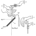
- FIG. The figure which shows the structure of the light source apparatus of Example 3.
- FIG. The figure which shows the optical path of red light in the light source apparatus of Example 3.
- FIG. The figure which shows the optical path of blue light in the light source apparatus of Example 3.
- FIG. The figure which shows the optical path of the fluorescent light in the light source apparatus of Example 3.
- FIG. The figure which shows the characteristic of the polarization separation membrane in Example 3.
- FIG. The figure which shows the spectral distribution of the light from the light source apparatus of Example 3.
- FIG. The figure which shows the color change by the brightness of the light source in Example 3.
- FIG. The figure which shows the structure of the light source apparatus of Example 3.
- FIG. The figure which shows the structure of the light source apparatus of Example 3.
- FIG. 1st blue light in the light source apparatus of Example 3. The figure which shows the optical path of the 2nd blue light and red light in the light source apparatus of Example 3.
- FIG. The figure which shows the structure of the polarization separation part of Example 5. The figure which shows the optical path of blue light in the light source apparatus of Example 5.
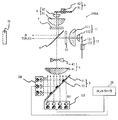
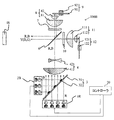
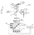
- FIG. 1 shows the configuration of the projector P as an image projection device on which any of the light source devices 100 (100A, 100A', 100B, 100C, 100D) of Examples 1 to 5 described later can be mounted.
- the projector P includes a light source device 100, an optical modulation unit (light modulation means) that modulates the light from the light source device 100, and a lens holding unit SU for holding a projection lens (projection optical system) PL. ..
- the projection lens (projection optical system) PL projects image light, which is light from the optical modulation unit, onto the screen (projected surface) SC.
- the optical modulation section is a general term for the light modulation section LP1 for red light, the light modulation section LP2 for green light, and the light modulation section LP3 for blue light, which will be described later.
- the light modulation units LP1 to LP3 all use a transmissive liquid crystal panel as a light modulation element.
- the lens holding portion SU may hold the projection lens PL detachably, or the projection lens PL may have a configuration in which the projection lens PL cannot be removed from the lens holding portion SU. Further, the holding unit SU may also have a function of shifting the held projection lens PL in a direction orthogonal to its optical axis.
- the projector P further includes an illumination optical system IS and a color separation composition system.
- the color separation / synthesis system is a general term for the dichroic mirrors DM1, DM2, mirrors M1, M2, M3, field lenses FL1, FL2, FL3, and relay lenses RL1, RL2, which will be described later.
- the red light R, green light G, and blue light B as the light emitted from the light source device 100 of each embodiment are incident on the dichroic mirror 1 via the illumination optical system IS.
- the dichroic mirror DM1 has a property of transmitting red light R and reflecting green light G and blue light B.
- the illumination optical system IS includes a fly-eye lens that divides light from a light source into a plurality of light beams, a polarization conversion unit that converts incident unpolarized light into linearly polarized light having a specific polarization direction, and the like, and makes the optical modulation unit uniform. Generates illumination light that illuminates with a uniform illumination distribution.
- the red light R transmitted through the dichroic mirror DM1 is incident on the light modulation unit LP1 for red light via the mirror M1 and the field lens FL1.
- the light modulation unit LP1 for red light is driven based on an image signal input from the outside to the projector to modulate the red light R.
- the modulated red light R is incident on the synthetic prism CP.
- the green light G reflected by the dichroic mirror DM1 is incident on the dichroic mirror DM2.
- the dichroic mirror DM2 has a property of reflecting green light G and transmitting blue light B.
- the green light G reflected by the dichroic mirror DM2 is incident on the light modulation unit LP2 for green light via the field lens FL2.
- the light modulation unit LP2 for green light is driven based on the above image signal to modulate the green light G.
- the modulated green light G is incident on the synthetic prism CP.
- the blue light B transmitted through the dichroic mirror DM1 is transmitted through the dichroic mirror DM2.
- the blue light B transmitted through the dichroic mirror DM2 is incident on the light modulation unit LP3 for blue light via the relay lens RL1, the mirror M2, the relay lens RL2, the mirror M3, and the field lens FL3.
- the light modulation unit LP3 for blue light is driven based on the above image signal to modulate the blue light B.
- the modulated blue light B is incident on the synthetic prism CP.
- the red light R, green light G, and blue light B incident on the synthetic prism CP are combined by the synthetic prism CP to become image light.
- the projection lens PL magnifies and projects the image light onto the screen SC. As a result, the projected image is displayed.
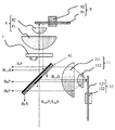
- FIG. 2 shows the configuration of the light source device 100A of the first embodiment.
- the light source device 100A includes a blue laser diode (LD) array 1B as a first light source that emits blue light B1 (wavelength 455 nm) as a first wavelength light and a first polarized light, and a second wavelength light and a second light source. It includes a blue LD array 2B as a second light source that emits blue light B2 (wavelength 455 nm) as the polarized light of 2.
- the blue light B2 has the same wavelength as the blue light B1, but the polarization direction is different by 90 degrees.
- the blue LD arrays 1B and 2B are composed of a plurality of GaN-based semiconductor LDs. However, this is only an example, and other semiconductor LDs may be used.
- blue light is light included in a band in which the wavelength of the maximum intensity or the full width at half maximum in the spectral intensity distribution of the light is 430 to 480 nm.
- green light is light included in a band in which the wavelength of the maximum intensity or the full width at half maximum in the spectral intensity distribution of the light is 500 to 580 nm.
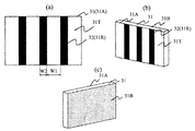
- the light source device 100A further includes a photosynthesis unit (photosynthesis element) 3 having a transmission region for transmitting blue light B1 and a reflection region for reflecting blue light B2.
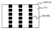
- the photosynthetic unit 3 has a plurality of photosynthetic units 3 on the surface 31A of the blue LD array 2B side (second light source side) of both surfaces of the transparent substrate (translucent substrate) 31. It has a configuration in which an aluminum reflective film 32 as a reflective portion is provided in a reflective region 31R which is a partial region.
- the transmission region is a plurality of regions 31T of the transparent substrate 31 on which the aluminum reflective film 32 is not provided. Further, as shown in FIG.
- an antireflection film is provided on the surface 31B of the blue LD array 1B side (first light source side) of both sides of the transparent substrate 31. This makes it possible to guide most of the blue light B1 from the blue LD array 1B to the photosynthesis unit 3.
- the photosynthesis unit 3 may have a configuration in which blue light B1 and B2 are synthesized by transmitting and reflecting them according to their polarization directions.
- the light source device 100A further includes a positive lens 41, a negative lens 42, and a compression optical system 4 that narrows the width of light from the photosynthetic unit 3.
- a compression optical system 4 that narrows the width of light from the photosynthetic unit 3.
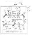
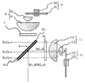
- the light source device 100A further includes a polarization separating unit (optical element) 6, a ⁇ / 4 plate (first ⁇ / 4 plate as a polarization rotating means) 7, a condensing optical system 8 including condensing lenses 81 and 82, and diffusion. It includes a body unit (diffusion means) 9.
- the diffuser unit 9 is composed of a diffuser wheel 91 and a motor 92 for rotating the diffuser wheel 91.
- the condensing optical system 8 guides the light from the ⁇ / 4 plate 7 to the diffuser wheel 91 and parallelizes the light while taking in the light from the diffuser wheel 91 to guide the light to the ⁇ / 4 plate 7.
- the diffuser wheel 91 is provided with a diffusion layer for diffusing the light from the ⁇ / 4 plate 7 in a ring shape on the aluminum substrate.
- a diffusion layer for diffusing the light from the ⁇ / 4 plate 7 in a ring shape on the aluminum substrate.
- the light source device 100A further includes a ⁇ / 4 plate (second ⁇ / 4 plate) 10, a condensing optical system 11 including condensing lenses 111 and 112, and a phosphor unit (wavelength conversion means) 12.
- the phosphor unit 12 is composed of a phosphor wheel 121 and a motor 122 for rotating the phosphor wheel 121.
- the condensing optical system 11 guides the light from the ⁇ / 4 plate 10 to the phosphor wheel 121 and parallelizes the light while taking in the light from the phosphor wheel 121 to guide the light to the ⁇ / 4 plate 10.
- the phosphor wheel 121 is provided with a ring-shaped yellow phosphor layer on an aluminum substrate for wavelength-converting the light (excitation light) from the ⁇ / 4 plate 10.
- the motor 122 By rotating the phosphor wheel 121 by the motor 122, it is possible to prevent the yellow phosphor layer from being continuously irradiated with the light from the ⁇ / 4 plate 10 at one fixed place in the yellow phosphor layer and deteriorated. ..
- the light source device 100A includes a controller 20 as a control means.
- the controller 20 configured by a computer such as a CPU executes a process of controlling driving (that is, light emission amount) of the blue LD array 1B and the blue LD array 2B according to a computer program.
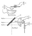
- FIG. 4 shows an optical path when the blue light B1 LD from the blue LD array 1B is guided to the illumination optical system IS via the diffuser unit 9.
- the blue light B1 LD from the blue LD array 1B is incident on the polarization separation membrane 612 of the polarization separation unit 6 together with the blue light B2 LD from the blue LD array 2B. Since the blue light B1 LD is P-polarized with respect to the polarization separation membrane 612, it is shown as B1 LD P in the figure, and since the blue light B2 LD is S-polarized, it is shown as B2 LD S.
- the polarizing separation membrane 612 is provided on the entire surfaces of both sides of the transparent substrate (translucent substrate) 611. However, the polarization separation membrane 612 may be provided on one side of the transparent substrate 611. This also applies to other examples described later.
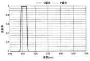
- FIG. 7 shows the characteristics of the polarizing separation membrane 612.
- Polarization splitting film 612 performs a polarization split for blue light B2 LD P from the blue light B1 LD S and blue LD array 2B from the blue LD array 1B, for the other wavelength light regardless of the polarization direction thereof It has the property of transmitting.
- the blue light B1 LDP transmitted through the polarization separation membrane 612 is converted into circularly polarized light by the ⁇ / 4 plate 7, condensed by the condensing optical system 8, and irradiated to the diffuser wheel 91.
- the blue light B1 LD diffused by the diffuser wheel 91 is converted into parallel light by the condensing optical system 8, converted into S-polarized light (polarized rotating light) by the ⁇ / 4 plate 7, and incident on the polarization separation film 612. Blue light B1 LD S became S polarized light is reflected by the polarization separating film 612 guided to the illumination optical system IS.
- FIG. 5 shows an optical path when the blue light B2 LD from the blue LD array 2B is guided to the illumination optical system IS via the phosphor unit 12.
- the blue light B2 LD S is a S-polarized light is reflected by the polarization splitting film 612.
- the reflected blue light B2 LD S is converted into circular polarization by the ⁇ / 4 plate 10, condensed by the condensing optical system 11, and incident on the yellow phosphor layer on the phosphor wheel 121.
- the yellow phosphor layer converts a part of blue light, which is excitation light, into yellow light (red light + green light) as fluorescent light (wavelength conversion light) having a wavelength longer than that of blue light.
- blue light B2 LDS blue light (hereinafter referred to as non-converted blue light) B2 F as unconverted light whose wavelength has not been converted by the yellow phosphor layer is parallelized by the condensing optical system 11 and ⁇ / It passes through the four plates 10 and is incident on the polarization separation film 612. Polarization direction of the non-converted blue light B2 F incident on the polarization separation film 612 is disturbed, S-polarized light component B2 F S of the non-converted blue light B2 F is returned to the blue LD array 2B is reflected by the polarization separating film 612 is, P-polarized light component B2 F P is guided to the illumination optical system iS is transmitted through the polarization splitting film 612.
- Figure 6 shows an optical path when the fluorescent light from the phosphor unit 12 (R F, G F) is guided to the illumination optical system IS.
- the green fluorescent light G F and the red fluorescence light R F is emitted from the yellow phosphor layer on the phosphor wheel 121.
- Fluorescent light incident on the polarization separation film 612 having the above-described characteristics (R F, G F) is guided to the illumination optical system IS is transmitted through the polarization separating film 612 regardless of the direction of polarization.
- the light source device 100A shown in FIG. 2 synthesizes the yellow light Y and the blue light B including the red light R and the green light G by the polarization separating unit 6, and directs the light to the illumination optical system IS as the emitted light. Exit.
- the luminance saturation of the phosphor contained in the yellow phosphor layer will be described.
- the light from the blue LD array 1B and the blue LD array 2B has a chromaticity of (0.14,0.04), and the fluorescent light has a chromaticity of (0.41, 0.57). It becomes.
- the amount of excitation light from the blue LD array 2B is increased, the amount of fluorescence light also increases, but the amount of light that returns as excitation light without being gradually converted to fluorescence increases. As a result, the amount of fluorescent light emitted from the phosphor decreases and shows a tendency to saturate.
- the amount of blue light emitted from the blue LD array 1B is constant, the amount of blue light emitted from the light source device 100A is constant. Therefore, when the amount of excitation light from the blue LD array 2B is increased and the amount of fluorescent light is increased, the chromaticity of the light emitted from the light source device 100A connects the chromaticity of the excitation light and the chromaticity of the fluorescent light from the chromaticity of the fluorescent light. It passes on the perpendicular and changes to approach the chromaticity of the excitation light.
- FIG. 8 shows the change in chromaticity of the light emitted from the light source device 100A with respect to the change in the amount of excitation light (B2 LD ) from the blue LD array 2B.
- the maximum value of the excitation light amount on the horizontal axis is 1 (150 W in this embodiment)
- the y value of the light emitted from the light source device 100A is shown on the vertical axis.
- the amount of excitation light is halved, the amount of fluorescent light decreases, so that the y value, which is the chromaticity of the light emitted from the light source device 100A, decreases from 0.38 to 0.29.
- FIG. 8 shows the change in chromaticity of the light emitted from the light source device 100A with respect to the change in the amount of light of the blue LD array 1B.
- the horizontal axis shows the maximum value of the amount of blue light from the blue LD array 1B as 1 (30 W in this embodiment), and the vertical axis shows the y value of the light emitted from the light source device 100A.
- the y value which is the chromaticity of the light emitted from the light source device 100A, increases from 0.38 to 0.46.
- the controller 20 records the change in chromaticity of the light emitted from the light source device 100A while changing the amount of light from the blue LD array 1B and the blue LD array 2B. For example, when the amount of light from the blue LD array 2B is changed to 1, 0.75, 0.5, the y values are recorded as 0.38, 0.34, 0.29, and the relationship is recorded as a lookup table. It is saved in the memory in the projector P. Similarly, when the amount of light from the blue LD array 1B is changed to 1, 0.75, 0.5, the y values are recorded as 0.30, 0.41, 0.46, and the relationship is recorded in the lookup table. It is saved in the above memory as.
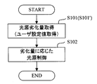
- the controller 20 first acquires the amount of deterioration of the blue LD array 1B and the blue LD array 2B (step S101).
- the amount of deterioration can be obtained by measuring the amount of light from each blue LD array using an optical sensor or detecting the temperature of each blue LD array using a temperature sensor.
- the amount of deterioration may be obtained from the history information of the lighting time of each blue LD array. Then, the controller 20 controls the driving of the blue LD arrays 1B and 2B as follows according to the amount of change in the amount of light from each blue LD array acquired from the deterioration amount (step S102).
- the controller 20 increases the drive current of the blue LD array 1B so as to reduce the amount of light of the blue LD array 1B by 29% from the amount of light at the initial use of the projector P. As a result, it is possible to suppress a change in the color of the light emitted from the light source device 100A.
- the user of the projector P can also set the amount of light emitted from the light source device 100A (hereinafter referred to as the brightness of the light source).
- the controller 20 acquires the brightness setting value (user setting value regarding the amount of emitted light) of the light source set by the user by the setting operation for the projector P, and the blue LD array 1B, according to the brightness setting value.
- the amount of light of at least one of 2 is changed (steps S101', 102 in FIG. 27).
- the controller 20 sets the amount of light emitted from the phosphor to 50% by setting the amount of light of the blue LD array 2B to 50%.
- the y value of the light emitted from the light source device 100A becomes 0.34, which is 0.04 lower than when the brightness of the light source is 100%. Assumed from the lookup table.
- the controller 20 increases the drive current of the blue LD array 1B so as to reduce the amount of light of the blue LD array 1B by 29%.
- the brightness of the light source set by the user can be obtained, and the change in the color of the light emitted from the light source device 100A can be suppressed.
- the amount of change in the amount of light emitted from the blue LD arrays 1B and 2B is different from that of the blue LD arrays 1B and 2B according to the change in the amount of light emitted from at least one of the blue LD arrays 1B and 2B.
- the light emission amount of at least one of the blue LD arrays 1B and 2B is controlled so that the ratio of the light emission amounts of the blue LD arrays 1B and 2B changes.
- the light source device 100A'of this embodiment has the same configuration as that of the first embodiment. That is, the light source device 100A'has a blue LD array 1B as a first light source that emits blue light B1 (wavelength 455 nm) as a first wavelength light and a first polarized light, and a second wavelength light and a second. It is provided with a blue LD array 2B as a second light source that emits blue light B2 (wavelength 465 nm) as polarized light.
- the blue light B2 has a different wavelength from the blue light B1 and the polarization direction is different by 90 degrees.
- the optical path of the blue light B1, the optical path of the blue light B2, and the optical path of the fluorescent light are as described with reference to FIGS. 4, 5 and 6, respectively, in the first embodiment.
- FIG. 9 shows the spectral intensity distribution of the light emitted from the light source device 100A'.
- the horizontal axis shows the wavelength and the vertical axis shows the light intensity.
- the wavelength of the blue LD array 1B is 465 nm, and the blue light of this wavelength is close to the chromaticity of blue in the sRGB color gamut. Since blue light of this wavelength is mainly projected from the light source device 100A', the tint of blue can be improved.
- the wavelength of the blue LD array 2B is 455 nm, the hue is inferior to that of the blue LD array 1B, but the excitation light irradiating the YAG phosphor used in this example has high excitation efficiency. Therefore, it is possible to perform fluorescence conversion more efficiently than in Example 1.
- the luminance saturation of the phosphor contained in the yellow phosphor layer becomes a problem.
- the light from the blue LD array 1B and the blue LD array 2B has a chromaticity of (0.13, 0.06), and the fluorescent light has a chromaticity of (0.41, 0.57). ..
- the amount of excitation light from the blue LD array 2B is increased, the amount of fluorescence light also increases, but the amount of light that returns as excitation light without gradual fluorescence conversion increases. As a result, the amount of fluorescent light emitted from the phosphor decreases and shows a tendency to saturate.
- the amount of blue light emitted from the blue LD array 1B is constant, the amount of blue light emitted from the light source device 100A'is constant. Therefore, when the amount of excitation light from the blue LD array 2B is increased and the amount of fluorescence light is increased, the chromaticity of the light emitted from the light source device 100A'is the chromaticity of the excitation light and the fluorescence light from the chromaticity of the fluorescence light. It passes on the line connecting the two and changes so as to approach the chromaticity of the excitation light.
- the change in the excitation light amount (B2 LD ) from the blue LD array 2B and the change in the chromaticity emitted from the light source device 100A'with respect to the change in the blue light amount (B1 LD ) of the blue LD array 1B are shown in FIG. As explained using.
- the controller 20 looks up the relationship between the amount of light and the chromaticity of the light emitted from the light source device 100A'while changing the amount of light from the blue LD arrays 1B and 2 as described in the first embodiment. Save to memory as a table.
- the amount of deterioration of the blue LD arrays 1B and 2 is acquired, the amount of increase in the amount of light of the blue LD array 1B corresponding to the decrease in the amount of light of the blue LD array 2B is obtained from the lookup table, and the drive current of the blue LD array 1B is increased. Let me.
- the amount of light of at least one of the blue LD arrays 1B and 2 may be changed according to the brightness setting value of the light source set by the user of the projector P.
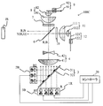
- FIG. 10 shows the configuration of the light source device 100B of the third embodiment.
- the light source device 100B includes a red LD array 1R as a first light source that emits red light R (wavelength 640 nm) as a first wavelength light and a first polarized light, and a second wavelength light and a second polarized light.
- a blue LD array 2B as a second light source that emits blue light B (wavelength 455 nm) is provided.
- the blue light B has a different wavelength from the red light R, and the polarization direction is different by 90 degrees.
- the blue LD array 2B is composed of a plurality of GaN-based semiconductor LDs
- the red LD array 1R is composed of a plurality of GaAs-based semiconductor LDs.
- red light refers to light included in a band in which the wavelength of maximum intensity or the full width at half maximum in the spectral distribution of the light is 600 to 750 nm.
- the light source device 100B further includes a photosynthetic unit 3 having a transmission region for transmitting red light R and a reflection region for reflecting blue light B.
- the photosynthesis unit 3 has the same configuration as that shown in FIGS. 3A to 3C, and most of the red light R from the red LD array 1R is guided to the photosynthesis unit 3.
- the photosynthesis unit 3 may have a configuration in which red light R and blue light B are combined by transmitting and reflecting them according to their polarization directions.
- the light source device 100B further includes a compression optical system 4 that narrows the width of the light from the positive lens 41, the negative lens 42, and the photosynthetic unit 3 as in the first embodiment.
- the light source device 100B further includes a polarizing separation unit 6, a ⁇ / 4 plate 7, a condensing optical system 8 including a condensing lens 81 and 82, a diffuser unit 9, a ⁇ / 4 plate 10, and a collection.
- It includes a condensing optical system 11 including optical lenses 111 and 112 and a phosphor unit 12.
- the configurations of the diffuser unit 9 and the phosphor unit 12 are the same as those in the first embodiment.
- the light source device 100B is also provided with a controller 20, and the controller 20 executes a process of controlling the drive (that is, the amount of light emission) of the red LD array 1R and the blue LD array 2B according to a computer program.
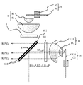
- FIG. 11 shows an optical path when the red light R LD from the red LD array 1R is guided to the illumination optical system IS via the diffuser unit 9.
- the red light R LD from the red LD array 1R is incident on the polarization separation membrane 612 of the polarization separation unit 6 together with the blue light B LD from the blue LD array 2B. Since the red light R LD is P-polarized with respect to the polarization separation membrane 612, it is indicated as R LD P in the figure, and the blue light B LD is indicated as B LD S because it is S-polarized.
- the polarizing separation membrane 612 is provided on the entire surfaces of both sides of the transparent substrate 611.
- FIG. 14 shows the characteristics of the polarizing separation membrane 612.
- Polarization splitting film 612 performs polarization separation for the blue light B LD P from the red light R LD S and blue LD array 2B from the red LD array 1R, for the other wavelength light regardless of the polarization direction thereof It has the property of being transparent.
- the red light R LDP transmitted through the polarization separation membrane 612 is converted into circularly polarized light by the ⁇ / 4 plate 7, condensed by the condensing optical system 8, and irradiated to the diffuser wheel 91.
- the red light R LD diffused by the diffuser wheel 91 is converted into parallel light by the condensing optical system 8, converted into S-polarized light (polarized rotating light) by the ⁇ / 4 plate 7, and incident on the polarization separation film 612.
- the red light R LD S became S polarized light is reflected by the polarization separating film 612 guided to the illumination optical system IS.
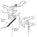
- FIG. 12 shows an optical path when the blue light B LD from the blue LD array 2B is guided to the illumination optical system IS via the phosphor unit 12.
- the blue light BLDS which is S-polarized light
- the reflected blue light BLDS is converted into circular polarization by the ⁇ / 4 plate 10, condensed by the focusing optical system 11, and incident on the yellow phosphor layer on the phosphor wheel 121.
- the yellow phosphor layer converts a part of blue light, which is excitation light, into yellow light (red light + green light) as fluorescent light having a wavelength longer than that of blue light.
- the unconverted blue light BF that was not wavelength-converted by the yellow phosphor layer is converted into parallel light by the condensing optical system 11 and passes through the ⁇ / 4 plate 10 to the polarization separation membrane 612. Incident. Polarization direction of the non-converted blue light B2 F incident on the polarization separation film 612 is disturbed, S-polarized light component B F S of the non-converted blue light B2 F is returned to the blue LD array 2B is reflected by the polarization separating film 612 is, P-polarized light component B F P is guided to the illumination optical system iS is transmitted through the polarization splitting film 612.
- Figure 13 shows an optical path when the fluorescent light from the phosphor unit 12 (R F, G F) is guided to the illumination optical system IS.
- the fluorescence light including the green fluorescent light G F and the red fluorescence light R F is emitted from the yellow phosphor layer on the phosphor wheel 121.
- Green fluorescent light G F incident on the polarization separation film 612 having the above properties is guided to the illumination optical system IS is transmitted through the polarization separating film 612 regardless of the direction of polarization.
- the light source device 100B shown in FIG. 10 synthesizes the yellow light Y and the blue light B including the red light R and the green light G by the polarization separating unit 6, and directs the light to the illumination optical system IS as the emitted light. Exit.
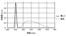
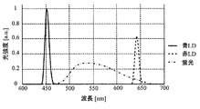
- FIG. 15 shows the spectral intensity distribution of the light emitted from the light source device 100B.
- the horizontal axis shows the wavelength and the vertical axis shows the light intensity.
- the wavelength of the red LD array 1R is 640 nm, and the red light of this wavelength is close to the chromaticity of red in the sRGB color gamut. Since red light of this wavelength is mainly projected from the light source device 100B, the tint of red can be improved.
- the excitation light for irradiating the YAG phosphor used in this example has high excitation efficiency. Therefore, it is possible to perform fluorescence conversion more efficiently than in Example 1.
- the light source device 100B of the present embodiment emits red light from the red LD array in addition to the blue light from the blue LD array and the fluorescent light from the yellow phosphor layer that can be emitted by the conventional light source device. be able to. That is, in the projector P equipped with the light source device 100B, as the red light used for image projection, as shown in FIG. 15, in addition to the red light contained in the fluorescent light from the yellow phosphor layer, the red light from the red LD array Light can also be used. As a result, the projector P using the light source device 100B of this embodiment can display a projected image brighter than that of the conventional projector.
- the number of blue LDs it is conceivable to increase the number of blue LDs to increase the amount of blue light incident on the yellow phosphor layer in order to increase the amount of red light contained in the fluorescent light.
- the brightness of the phosphor is increased because the amount of red light is increased by using the red LD array instead of increasing the amount of red light contained in the fluorescent light. It is possible to display a projected image brighter than before without being limited by the limit due to the saturation characteristic.
- the amount of red light is insufficient. Therefore, when projecting an all-white image whose entire surface is white, the amount of green light is adjusted to match the small amount of red light. It was necessary to reduce the amount of blue light and adjust the balance of white. More specifically, when the light modulation unit is a reflective type, the reflectance of the light modulation unit for both color light is lowered for green light and blue light to reduce the amount of green light and the amount of blue light guided to the screen. I needed it. As a result, the brightness of the all-white image is reduced in the conventional projector.
- the light source device 100B of the present embodiment since the amount of red light is increased by using the red light from the red LD array, it is not necessary to reduce the amount of green light and the amount of blue light in the light modulation unit. It is possible to suppress a decrease in brightness.
- a red LD that emits red light having a wavelength longer than 640 nm is also provided to provide a wider color than before. It is possible to reproduce the area.
- the light source device 100B of the present embodiment since the light from the two light sources is combined by one photosynthetic unit, it is possible to obtain the effect of improving the brightness while suppressing the increase in size of the light source device.
- the luminance saturation of the phosphor contained in the yellow phosphor layer becomes a problem.
- the light from the blue LD array 2B has a chromaticity of (0.14,0.04), and the fluorescent light has a chromaticity of (0.41, 0.57).
- the light from the red LD array 1R has a chromaticity of (0.72, 0.28).
- Example 1 As described in Example 1, as the amount of excitation light from the blue LD array 2B is increased, the amount of fluorescence light also increases, but the amount of light that returns as excitation light without gradual fluorescence conversion increases. As a result, the amount of fluorescent light emitted from the phosphor decreases and shows a tendency to saturate. Therefore, when the amount of excitation light from the blue LD array 2B is increased, both the amount of fluorescence light and the amount of excitation light that has not been fluorescently converted increase, but the amount of excitation light relatively increases due to the luminance saturation characteristics of the phosphor.
- the chromaticity of the light emitted from the light source device 100B changes from the chromaticity of the fluorescent light to approach the chromaticity of the excitation light through the line connecting the chromaticity of the excitation light and the fluorescence light. For this reason, conventionally, when projecting an all-white image, it has been necessary to balance the fluorescence light and the excitation light and keep the chromaticity constant. More specifically, when the light modulation unit is a reflective type, the reflectance of the excessive color light modulation unit is lowered to reduce the amount of light guided to the screen to keep the chromaticity constant. I had to make some adjustments.
- the optical modulation unit makes adjustments to keep the chromaticity of all white constant, but also the chromaticity of the single red color must be kept constant.
- the gamut changes. This is because the light emitted from the light source device 100B of this embodiment includes red fluorescent light and red light from the red LD array 1R, and the chromaticity is determined by the composite spectrum of these, so that the red fluorescent light This is because the chromaticity changes when the mixing ratio of the red light from the red LD array 1R and the red light is different. Therefore, in this embodiment, the amount of red light from the red LD array 1R is adjusted so that the mixing ratio of the red fluorescent light and the red light from the red LD array 1R is equal.
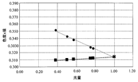
- FIG. 16 shows the change in chromaticity of the light emitted from the light source device 100B with respect to the change in the amount of excitation light ( BLD ) from the blue LD array 2B.
- the maximum value of the excitation light amount on the horizontal axis is 1 (150 W in this embodiment), and the y value of the light emitted from the light source device 100B is shown on the vertical axis.
- the amount of excitation light when the amount of excitation light is halved, the amount of light that returns as excitation light without fluorescence conversion decreases and the amount of fluorescence light increases, so this is the chromaticity of the light emitted from the light source device 100B.
- the x value increases from 0.314 to 0.343.
- FIG. 16 shows the change in chromaticity of the light emitted from the light source device 100B with respect to the change in the amount of red light from the red LD array 1R.
- the maximum value of the amount of red light is 1 (15 W in this embodiment)
- the vertical axis shows the x value of the light emitted from the light source device 100B.
- the x value which is the chromaticity of the light emitted from the light source device 100B, decreases from 0.314 to 0.310.
- the controller 20 records the change in chromaticity of the light emitted from the light source device 100B while changing the amount of light from the red LD array 1R and the blue LD array 2B. For example, when the amount of light from the blue LD array 2B is changed to 1, 0.75, 0.5, the x values are recorded as 0.314, 0.328, 0.343, and the relationship is recorded as a lookup table. It is saved in the memory in the projector P.
- the controller 20 first acquires the deterioration amounts of the red LD array 1R and the blue LD array 2B (step S101), and the red color and the red color acquired from the deterioration amounts are obtained.
- the drive of the red and blue LD arrays 1R and 2B is controlled according to the amount of change in the light emission amount of the blue LD arrays 1R and 2B (step S102).
- the method for obtaining the amount of deterioration is as described in Example 1.
- the controller 20 increases the drive current of the red LD array 1R so as to reduce the light intensity of the red LD array 1R by 45% from the initial light intensity of the projector P (step S102). As a result, it is possible to suppress a change in the color of the light emitted from the light source device 100B.
- the controller 20 acquires the brightness setting value of the light source set by the user by the setting operation for the projector P, and changes the light amount of the blue LD array 2B according to the brightness setting value (FIG. 27). Steps S101', S102).
- the controller 20 reduces the amount of light of the blue LD array 2B so that the amount of light emitted from the light source device 100B is 55% of the maximum output.
- the controller 20 sets the amount of light emitted from the phosphor to 55% by setting the amount of light of the blue LD array 2B to 50%.
- the x value of the light emitted from the light source device 100B becomes 0.343, which is 0.029 lower than when the brightness of the light source is 100%. Assumed from the lookup table.
- the controller 20 reduces the drive current of the red LD array 1R so as to reduce the amount of light of the red LD array 1R by 45%.
- the brightness of the light source set by the user can be obtained, and the change in the color of the light emitted from the light source device 100B can be suppressed.
- the amount of change in the amount of light emitted from the red and blue LD arrays 1R and 2B changes according to the change in the amount of light emitted from at least one of the red and blue LD arrays 1R and 2B.
- the emission amount of at least one of the red and blue LD arrays 1R and 2B is controlled so as to be different from each other or so that the ratio of the emission amounts of the red and blue LD arrays 1R and 2B is changed.
- the red light from the red LD array 1R is transmitted through the photosynthesis unit 3, and the blue light from the blue LD array 2B is reflected by the photosynthesis unit 3.
- the light amount loss in transmission is smaller. Therefore, as in the light source device 100B, by configuring the red light from the red LD array 1R to pass through the photosynthetic unit 3, it is possible to supplement more of the red light that was conventionally lacking as described above. It becomes.
- the shortage of red light is further reduced by making the number of red LDs contained in the red LD array 1 larger than the number of blue LDs contained in the blue LD array 2B. It becomes possible.
- the photosynthesis unit 3 it is desirable to configure the photosynthesis unit 3 so that the area of the transmission region 31T is larger than the area of the reflection region 31R. In other words, it is desirable that the width W1 of the transmission region 31T is wider than the width W2 of the reflection region 31R. According to this configuration, even if the arrangement position of the red LD array 1R deviates from the normal position due to a mounting error or the like, it is possible to suppress that the light from the red LD array 1R is blocked by the reflecting unit 32. Become.
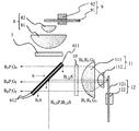
- FIG. 17 shows the configuration of the light source device 100C of the fourth embodiment.
- the light source device 100C includes a red LD array 1R as a first light source that emits red light R (wavelength 640 nm) as a first wavelength light and a first polarized light, and a second wavelength light and a second polarized light.
- a blue LD array 2B as a second light source that emits blue light B2 (wavelength 455 nm)
- a third light source that emits blue light B3 (wavelength 465 nm) as a third wavelength light and a third polarized light.
- the blue LD array 3B is provided.
- the wavelength of the blue light B3 is different from that of the blue light B2.
- the red light R and the blue light B3 have the same polarization direction as each other, and the polarization direction is 90 degrees different from that of the blue light B2.
- the blue LD array 3B which is the third light source, should be regarded as a first light source different from the red LD array 1R, which is the first light source, with respect to the blue LD array 2B, which is the second light source. Can be done.
- the light source device 100C further includes a photosynthetic unit 3 having a transmission region for transmitting red light R and a reflection region for reflecting blue light B2 and B3.
- the photosynthesis unit 3 has the same configuration as the photosynthesis unit 3 described with reference to FIGS. 3A to 3C in Example 1. That is, it has a configuration in which an aluminum reflective film 32 as a reflective portion is provided in a reflective region 31R which is a plurality of partial regions on the surface 31A on the blue LD array 2B side (second light source side) of both sides of the transparent substrate 31. ..
- the transmission region is a plurality of regions 31T of the transparent substrate 31 on which the aluminum reflective film 32 is not provided.
- antireflection films are provided on the surfaces 31B of the red LD array 1R and the blue LD array 3B side (first and third light source sides) of both sides of the transparent substrate 31. As a result, most of the red light R and the blue light B3 from the red LD array 1R and the blue LD array 3B can be guided to the photosynthesis unit 3.
- the photosynthesis unit 3 may have a configuration in which red light R, blue light B3, and blue light B2 are combined by transmitting and reflecting them according to their polarization directions.
- the light source device 100C further includes a compression optical system 4 that narrows the width of the light from the positive lens 41, the negative lens 42, and the photosynthetic unit 3 as in the first embodiment.
- the light source device 100C further includes a polarizing separation unit 6, a ⁇ / 4 plate 7, a condensing optical system 8 including a condensing lens 81 and 82, a diffuser unit 9, a ⁇ / 4 plate 10, and a collection.
- It includes a condensing optical system 11 including optical lenses 111 and 112 and a phosphor unit 12.
- the configurations of the diffuser unit 9 and the phosphor unit 12 are the same as those in the first embodiment.
- the light source device 100C is also provided with a controller 20, and the controller 20 executes a process of controlling driving (that is, light emission amount) of the red LD array 1R, the blue LD array 2B, and the blue LD array 3B according to a computer program. To do.
- FIG. 18 shows an optical path when the red light R LD from the red LD array 1R and the blue light B3 LD from the blue LD array 3B are guided to the illumination optical system IS via the diffuser unit 9.
- the red light R LD from the red LD array 1R and the blue light B3 LD from the blue LD array 3B are incident on the polarization separation film 612 of the polarization separation unit 6 together with the blue light B2 LD from the blue LD array 2B. Since the red light R LD and the blue light B3 LD are P-polarized with respect to the polarization separation membrane 612, they are shown as R LD P and B3 LD P in the figure, respectively, and the blue light B2 LD is S-polarized and therefore B2 LD. It is shown as S.
- the polarizing separation membrane 612 is provided on the entire surfaces of both sides of the transparent substrate 611.
- Polarization separation film 612 in this embodiment transmits the red light R LD P and blue light B3 LD P, reflects the blue light B3 LD P and blue light B2 LD S.
- the P-polarized red light R LD P and blue light B3 LD P transmitted through the polarization separation membrane 612 are converted into circularly polarized light by the ⁇ / 4 plate 7, condensed by the condensing optical system 8, and irradiated to the diffuser wheel 91. Will be done.
- the red light R LD and blue light B3 LD diffused by the diffuser wheel 91 are parallelized by the condensing optical system 8 and converted into S-polarized light (polarized rotating light) by the ⁇ / 4 plate 7, and are polarized separation membranes. It is incident on 612.
- the red light R LD S and blue light B3 LD S became S polarized light, respectively, are reflected by the polarization separating film 612 guided to the illumination optical system IS.
- FIG. 19 shows an optical path when the blue light B2 LD from the blue LD array 2 is guided to the illumination optical system IS via the phosphor unit 12.
- the blue light B2 LD S is a S-polarized light is reflected by the polarization splitting film 612.
- the reflected blue light B2 LD S is converted into circular polarization by the ⁇ / 4 plate 10, condensed by the condensing optical system 11, and incident on the yellow phosphor layer on the phosphor wheel 121.
- the yellow phosphor layer converts a part of blue light, which is excitation light, into yellow light (red light + green light) as fluorescent light having a wavelength longer than that of blue light.
- the unconverted blue light B2 F whose wavelength was not converted by the yellow phosphor layer is converted into parallel light by the condensing optical system 11 and passes through the ⁇ / 4 plate 10 to the polarization separation membrane 612. Incident. Polarization direction of the non-converted blue light B2 F incident on the polarization separation film 612 is disturbed, S-polarized light component B2 F S of the non-converted blue light B2 F is returned to the blue LD array 2B is reflected by the polarization separating film 612 is, P-polarized light component B2 F P is guided to the illumination optical system iS is transmitted through the polarization splitting film 612.
- Figure 20 shows an optical path when the fluorescent light from the phosphor unit 12 (R F, G F) is guided to the illumination optical system IS.
- the green fluorescent light G F and the red fluorescence light R F is emitted from the yellow phosphor layer on the phosphor wheel 121.
- Fluorescent light incident on the polarization separation film 612 having the above-described characteristics (R F, G F) is guided to the illumination optical system IS is transmitted through the polarization separating film 612 regardless of the direction of polarization.
- the light source device 100C shown in FIG. 17 synthesizes the yellow light Y and the blue light B including the red light R and the green light G by the polarization separating unit 6, and directs the light to the illumination optical system IS as the emitted light. Exit.
- the luminance saturation of the phosphor contained in the yellow phosphor layer becomes a problem.
- the light from the blue LD array 2B has a chromaticity of (0.14,0.04)
- the light from the blue LD array 3B has a chromaticity of (0.13,0.06).
- the fluorescent light has a chromaticity of (0.41, 0.57)
- the light from the red LD array 1R has a chromaticity of (0.72, 0.28).
- Example 1 As described in Example 1, as the amount of excitation light from the blue LD array 2B is increased, the amount of fluorescence light also increases, but the amount of light that returns as excitation light without gradual fluorescence conversion increases. Therefore, the amount of light emitted from the phosphor decreases and shows a tendency to saturate.
- the amount of light from the blue LD array 3 is constant, the amount of blue light emitted from the light source device is constant. Therefore, as the amount of excitation light from the blue LD array 2B is increased, the amount of fluorescent light increases. Therefore, the chromaticity of the light emitted from the light source device 100C is determined from the chromaticity of the fluorescent light to the chromaticity of the excitation light and the fluorescent light. It changes so as to approach the chromaticity of the excitation light through the line connecting the two.
- the change in the chromaticity (y value) of the light emitted from the light source device 100C with respect to the change in the amount of excitation light (B2 LD ) from the blue LD array 2B is as shown by ⁇ in FIG.
- the amount of excitation light is halved, the amount of fluorescent light decreases, so that the y value, which is the chromaticity of the light emitted from the light source device 100C, decreases from 0.38 to 0.29.
- the amount of light from the blue LD array 3B is reduced. If the amount of light from the other blue LD array 2B is constant, the amount of fluorescent light from the phosphor is constant. Therefore, when the amount of light from the blue LD array 3B decreases, the chromaticity of the light emitted from the light source device 100C approaches the chromaticity of the fluorescent light through the line connecting the chromaticity of the excitation light and the fluorescence light. Change. In this embodiment, the change in the chromaticity (y value) of the light emitted from the light source device 100C with respect to the change in the amount of excitation light (B3 LD ) from the blue LD array 3B is as shown by (3) in FIG.
- the y value which is the chromaticity of the light emitted from the light source device 100C, is It increases from 0.38 to 0.46.
- the controller 20 records the change in the chromaticity of the light emitted from the light source device 100C while changing the amount of light from the blue LD array 2B and the blue LD array 3B. For example, when the amount of light from the blue LD array 2B is changed to 1, 0.75, 0.5, the y values are recorded as 0.38, 0.34, 0.29, and the relationship is recorded as a lookup table. It is saved in the memory in the projector P. Similarly, when the amount of light from the blue LD array 3B is changed to 1, 0.75, 0.5, the y values are recorded as 0.30, 0.41, 0.46, and the relationship is recorded in the lookup table. It is saved in the above memory as.
- the controller 20 first acquires the deterioration amounts of the blue LD array 2B and the blue LD array 3B (step S101), and the blue LD acquired from the deterioration amounts.
- the drive of the blue LD arrays 2B and 3B is controlled according to the amount of change in the amount of light emitted from the arrays 2B and 3B (step S102).
- the method for obtaining the amount of deterioration is as described in Example 1.
- the controller 20 increases the drive current of the blue LD array 3B so as to reduce the light intensity of the blue LD array 3B by 29% from the initial light intensity of the projector P.
- the controller 20 adjusts the amount of red light from the red LD array 1R so that the mixing ratio of the red fluorescent light and the red light from the red LD array 1R becomes equal as in the third embodiment. ..
- the controller 20 records the change in chromaticity of the light emitted from the light source device 100C while changing the amount of light of the red LD array 1R and the blue LD array 2B. Then, the change in the amount of red light emitted from the light source device 100C corresponding to the change in chromaticity is calculated, and the amount of red light in the red LD array 1R that substantially matches the change in the amount of red light is stored in the memory as a lookup table. ..
- the x values are recorded as 0.314, 0.328, 0.343, and the relationship is recorded as a lookup table. It is saved in the memory in the projector P.
- the y values are recorded as 0.378, 0.403, 0.423, and the relationship is recorded in the lookup table. It is saved in the above memory as.
- the controller 20 first acquires the deterioration amount of the red LD array 1R and the blue LD array 2B (step S101), and the red color and the red color acquired from the deterioration amount are obtained.
- the drive of the red and blue LD arrays 1R and 2B is controlled according to the amount of change in the light emission amount of the blue LD arrays 1R and 2B (step S102).
- the method for obtaining the amount of deterioration is as described in Example 1.
- the controller 20 reduces the drive current of the red LD array 1 so that the amount of red light from the red LD array 1R is reduced by 45% from the amount of light at the initial use of the projector P. As a result, it is possible to suppress a change in the color of the light emitted from the light source device 100C.
- the controller 20 acquires the brightness setting value of the light source set by the user by the setting operation for the projector P, and sets the amount of light of at least one of the blue LD arrays 2B and 3B according to the brightness setting value. Change ((steps S101', 102 in FIG. 27)).
- the controller 20 sets the amount of light emitted from the phosphor to 50% by setting the amount of light of the blue LD array 2B to 50%.
- the y value of the light emitted from the light source device 100A becomes 0.34, which is 0.04 lower than when the brightness of the light source is 100%. Assumed from the lookup table.
- the controller 20 increases the drive current of the red LD array 1R so as to reduce the amount of red light from the red LD array 1R by 29%. As a result, the brightness of the light source set by the user can be obtained, and the change in the color of the light emitted from the light source device 100C can be suppressed.
- the controller 20 in the present embodiment emits light from the red and blue LD arrays 1R, 2B and 3B according to a change in the light emission amount of at least one of the red and blue LD arrays 1R, 2B and 3B.
- the amount of light emitted from at least one of the red and blue LD arrays 1R, 2B, 3B is controlled so that the amount of change in the red and blue LD arrays 1R, 2B, 3B changes. ..
- the change in the color of the light emitted from the light source device 100C can be suppressed.
- Examples 1 to 4 the configuration using the ⁇ / 4 plate 10 is shown, but the ⁇ / 4 plate 10 may not be used.
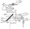
- FIG. 21 shows the configuration of the light source device 100D of the fifth embodiment.
- the light source device 100D of the present embodiment has a polarization separation unit 61 having a configuration different from that of the polarization separation unit 6 provided in the light source device 100 of the third embodiment, and ⁇ / provided in the light source device 100 of the third embodiment. It does not have 4 plates 10. Further, the light source device 100D of the present embodiment includes a ⁇ / 2 plate 5 which is not provided in the light source device 100 of the third embodiment.
- the light source device 100D is also provided with a controller 20, and the controller 20 executes a process of controlling driving (that is, light emission amount) of the red LD array 1R and the blue LD array 2B according to a computer program.
- 22 (a), (b), and (c) show the configuration of the polarization separating unit 61.
- the polarization separation unit 61 includes a transparent substrate (translucent substrate) 611 and a polarization separation membrane (hereinafter, incident side polarization separation) provided on the incident side surface of the transparent substrate 611.
- the polarizing separation films 612a and 612b perform polarization separation for blue light from the blue LD array 2B and red light from the red LD array 1R, and polarize light of other wavelengths. It has the property of transmitting light regardless of the direction.
- the polarization separation film 612 was provided on the entire surface of the transparent substrate 611 on the incident side.
- the incident side polarizing separation film 612a is provided on a part of the incident side surface of the transparent substrate 611.
- the phase difference imparting portion 613 is provided in a region (around the incident side polarizing separation membrane 612) different from the region in which the incident side polarizing separation membrane 612a is provided.
- the phase difference imparting unit 613 has a characteristic of converting the S-polarized light incident therein into P-polarized light and converting the P-polarized light into S-polarized light (that is, rotating the polarization direction by 90 °).
- the light emitting side polarizing separation film 612b is provided on the entire surface of the transparent substrate 611 on the light emitting side.
- the incident side polarizing separation membrane 612a is arranged so that most of the light from the compression optical system 4 is incident.
- the area of the incident side polarization separation membrane 612a is larger than the area where the light from the compression optical system 4 is incident on the incident side surface of the polarization separation unit 61. It is getting wider.
- FIG. 23 shows an optical path when the blue light B LD from the blue LD array 2B is guided to the illumination optical system IS via the diffuser unit 9 and the phosphor unit 12.
- a part of the blue light BLDS as S-polarized light from the blue LD array 2B is incident on the ⁇ / 2 plate 5 and converted into blue light BLDP P as P-polarized light.
- the blue light BLDP P which is P-polarized light, passes through the incident-side and outgoing-side polarized light separation films 612a and 612b, is converted into circularly polarized light by the ⁇ / 4 plate 7, and is condensed by the condensing optical system 8 to be a diffuser.
- the diffuser wheel 91 of the unit 9 is irradiated.
- the blue light B LD diffused by diffuser wheel 91 is collimated by the focusing optical system 8, lambda / 4 S-polarized light by the plate 7 (polarization rotation light) B LD S is converted into that in the exit side polarization separation film It is reflected by 612b and guided to the illumination optical system IS.
- the blue light BLDS which is S-polarized light that has not been converted into P-polarized light by the ⁇ / 2 plate 5
- the incident-side polarization separation membrane 612a of the polarization separation unit 61 is reflected by the incident-side polarization separation membrane 612a of the polarization separation unit 61 and guided to the phosphor unit 12 for fluorescence. It is incident on the yellow phosphor layer on the body wheel 121.
- a part of the blue light BLDS incident on the yellow phosphor layer is wavelength-converted to fluorescent light.
- the unconverted blue light BF which has not been wavelength-converted by the yellow phosphor layer, is converted into parallel light by the condensing optical system 11 and incident on the polarization separation unit 61.
- the polarization direction of the unconverted blue light incident on the polarization separation unit 61 is disturbed.
- Some of the S-polarized component B F S of the non-converted blue light B F is returned to the blue LD array 2B is reflected by the incident-side polarization separation film 612a.
- S-polarized light component B F S incident on the phase difference providing unit 613 is guided to the illumination optical system IS transmitted through the exit side polarization separation film 612b is converted into blue light B F P as P-polarized light.
- FIG. 24 shows an optical path when the red light R LD from the red LD array 1R is guided to the illumination optical system IS via the diffuser unit 9 and the phosphor unit 12.
- Red LD red light R LD red light is to be converted P-polarized light into P R LD P as part of the red light R LD S as S polarized light from the array 1R is incident to the lambda / 2 plate 5
- the body wheel 91 is irradiated.
- the red light R LD diffused by the diffuser wheel 91 is converted into parallel light by the condensing optical system 8 and converted into S polarized light (polarized rotating light) R LD S by the ⁇ / 4 plate 7, and the emitting side polarizing separation film. It is reflected by 612b and guided to the illumination optical system IS.
- the red light RLD S which is S-polarized light that has not been converted into P-polarized light by the ⁇ / 2 plate 5, is reflected by the incident-side polarization separation membrane 612a and guided to the phosphor unit 12, and is guided on the phosphor wheel 121. It is incident on the yellow phosphor layer.
- the red light RLDS is not fluorescently converted in the yellow phosphor layer, its polarization direction is disturbed, and it returns to the polarization separation unit 61 via the condensing optical system 11.
- red light R LD returned from the phosphor unit 12 to the polarization separation unit 61 a part of the S polarization component R LD S is reflected by the incident side polarization separation membrane 612a and returned to the red LD array 1R. Further, the S polarization component R LD S incident on the phase difference imparting unit 613 is converted into red light R LD P as P polarization, transmitted through the emission side polarization separation film 612b, and guided to the illumination optical system IS.
- Figure 25 shows an optical path when the fluorescent light R F from the phosphor unit 12, G F is guided to the illumination optical system IS.
- the incident side polarization separation film 612a fluorescent light R F
- a part of the red light R LD red fluorescent light R F having a wavelength different from the from the red light LD array 1R of G F
- the incident polarized light separating unit 61 It is guided to the illumination optical system 612 through the polarization separation films 612a and 612b on the side and the exit side.
- the light source device 100D shown in FIG. 21 synthesizes the yellow light Y and the blue light B including the red light R and the green light G by the polarization separating unit 6, and directs the light to the illumination optical system IS as the emitted light. Exit.
- the configuration in which the red light from the red LD array 1R passes through the photosynthesis unit 3 and the blue light from the blue LD array 2B is reflected by the photosynthesis unit 3 has been described.
- the red light from the red light LD array 1R may be reflected by the photosynthesis unit 3, and the blue light from the blue LD array 2B may be transmitted through the photosynthesis unit 3. That is, one of the first polarized light and the second polarized light may be transmitted and the other may be reflected. This is the same in Examples 1 and 2.
- the configuration in which the photosynthetic unit 3 includes an aluminum reflective film as a reflective unit has been described.
- a dichroic film that reflects the blue light from the blue LD array 2B and transmits the red light from the red LD array 1R may be used. This is the same in Examples 1 and 2. Further, in Examples 1 to 5, a reflection mirror may be used as the reflection unit of the photosynthesis unit 3.
- the photosynthesis unit 3 may have the configuration shown in FIG. 26.
- a plurality of finer reflecting portions are arranged in an array instead of the strip-shaped reflecting portions as shown in FIG. 3A.
- Examples 1 to 5 a case where the light transmitted through the polarizing separation units 6 and 61 is guided to the diffuser unit 9 and the light reflected by the polarization separation units 6 and 61 is guided to the phosphor unit 12 will be described. did. However, the light reflected by the polarization separating portion may be guided to the diffuser unit, and the light transmitted through the polarization separating portion may be guided to the phosphor unit. That is, it is sufficient that one of the first and second polarized lights is transmitted and the other is reflected in the polarization separating unit.
Abstract
【課題】光源からの光の明るさが変化した場合の色味の変化を抑制する。 【解決手段】光源装置100Aは、第1の偏光光を発する第1の光源1Bと、第2の偏光光を発する第2光源2Bと、一方の偏光光を透過させて他方の偏光光を反射する光学素子6と、光学素子からの第1の偏光光の偏光方向を回転させて偏光回転光を生成する偏光回転手段9と、光学素子からの第2の偏光光を波長変換光に変換する波長変換手段11とを有する。光学素子は、波長変換光と偏光回転光とを合成して出射光を生成する。制御手段20は、第1および第2の光源のうち少なくとも一方の光源の発光量の変化に応じて、第1の光源の発光量の変化量と第2の光源の発光量の変化量とが異なるように又は第1の光源の発光量と第2の光源の発光量との比が変化するように、第1および第2の光源のうち少なくとも一方の光源の発光量を制御する。
Description
本発明は、画像投射装置(プロジェクタ)等に好適な光源装置に関する。
青色光を発する青色レーザーダイオード(LD)と、青色LDからの青色光の一部を蛍光光としての黄色光(緑色光+赤色光)に変換する蛍光体(以下、黄色蛍光体という)とを用いてカラー画像を投射表示するプロジェクタが特許文献1に開示されている。このプロジェクタでは、2つの青色LDアレイからの青色光を、交互に配置された透過領域と反射領域とを有する光合成部で合成し、合成した青色光の一部を蛍光体に導く光源装置を用いている。
黄色蛍光体は、緑色光と赤色光を発するが、緑色光の光量に対して赤色光の光量が不足する傾向がある。このため、画像投射に用いられる赤色光が黄色蛍光体から発せられた赤色光だけである特許文献1のプロジェクタでは、赤味がかった投射画像を十分な明るさで表示することが困難である。
また、青色LDからの青色光についても、黄色蛍光体での変換効率が高い青の波長と投射画像における青の色味を改善できる青の波長とが異なっており、投射画像の明るさと色味の双方を改善することは難しい。
本発明は、光源からの光の色味と明るさとを改善することができ、また明るさが変化した場合の色味の変化を抑制することが可能な光源装置およびこれを用いた画像投射装置を提供する。
本発明の一側面としての光源装置は、第1の偏光光を発する第1の光源と、第1の偏光光とは偏光方向が異なる第2の偏光光を発する第2光源と、第1および第2の偏光光のうち一方の偏光光を透過させて他方の偏光光を反射する光学素子と、該光学素子からの第1の偏光光の偏光方向を回転させて偏光回転光を生成する偏光回転手段と、光学素子からの第2の偏光光を該第2の偏光光とは波長が異なる波長変換光に変換する波長変換手段とを有する。光学素子は、波長変換光と偏光回転光とを合成して出射光を生成する。そして、第1および第2の光源のうち少なくとも一方の光源の発光量の変化に応じて、第1の光源の発光量の変化量と第2の光源の発光量の変化量とが異なるように又は第1の光源の発光量と第2の光源の発光量との比が変化するように、第1および第2の光源のうち少なくとも一方の光源の発光量を制御する制御手段を有することを特徴とする。なお、上記光源装置を備えた画像投射装置も、本発明の他の一側面を構成する。
また、上記光源装置の制御方法であって、第1および第2の光源のうち少なくとも一方の光源の発光量の変化を取得するステップと、該変化に応じて、第1の光源の発光量の変化量と第2の光源の発光量の変化量とが異なるように又は第1の光源の発光量と第2の光源の発光量との比が変化するように、第1および第2の光源のうち少なくとも一方の光源の発光量を制御するステップとを有する制御方法も、本発明の他の一側面を構成する。さらに上記光源装置のコンピュータに上記制御方法に従う処理を実行させるコンピュータプログラムも、本発明の他の一側面を構成する。
本発明によれば、光源装置からの光の色味と明るさを改善することができ、また明るさが変化した場合の色味の変化を抑制することができる。
以下、本発明の実施例について図面を参照しながら説明する。
図1は、後述する実施例1~5の光源装置100(100A,100A′,100B,100C,100D)のいずれかが搭載可能な画像投射装置としてのプロジェクタPの構成を示している。プロジェクタPは、光源装置100と、光源装置100からの光を変調する光変調部(光変調手段)と、投射レンズ(投射光学系)PLを保持するためのレンズ保持部SUとを備えている。投射レンズ(投射光学系)PLは、光変調部からの光である画像光をスクリーン(被投写面)SCに投射する。
光変調部は、後述する赤色光用の光変調部LP1、緑色光用の光変調部LP2および青色光の光変調部LP3の総称である。図1において、光変調部LP1~LP3はいずれも、透過型の液晶パネルを光変調素子として用いている。
レンズ保持部SUは、投射レンズPLを着脱可能に保持してもよいし、投射レンズPLがレンズ保持部SUから取り外せない構成であってもよい。また保持部SUは、保持した投射レンズPLをその光軸に直交する方向にシフトさせる機能も有していてもよい。
プロジェクタPはさらに、照明光学系ISと、色分離合成系とを備えている。色分離合成系は、後述するダイクロイックミラーDM1,DM2、ミラーM1,M2,M3、フィールドレンズFL1,FL2,FL3およびリレーレンズRL1,RL2の総称である。
各実施例の光源装置100からの出射光としての赤色光R、緑色光Gおよび青色光Bは、照明光学系ISを介してダイクロイックミラー1に入射する。ダイクロイックミラーDM1は、赤色光Rを透過させ、緑色光Gと青色光Bを反射する特性を有する。照明光学系ISは、光源からの光を複数の光束に分割するフライアイレンズや入射した無偏光光を特定の偏光方向を有する直線偏光に変換する偏光変換部等を含み、光変調部を均一な照度分布で照明する照明光を生成する。
ダイクロイックミラーDM1を透過した赤色光Rは、ミラーM1とフィールドレンズFL1を介して赤色光用の光変調部LP1に入射する。赤色光用の光変調部LP1は、プロジェクタに外部から入力された画像信号に基づいて駆動されて赤色光Rを変調する。変調された赤色光Rは、合成プリズムCPに入射する。
ダイクロイックミラーDM1によって反射された緑色光Gは、ダイクロイックミラーDM2に入射する。ダイクロイックミラーDM2は、緑色光Gを反射して青色光Bを透過させる特性を有する。ダイクロイックミラーDM2によって反射された緑色光Gは、フィールドレンズFL2を介して緑色光用の光変調部LP2に入射する。緑色光用の光変調部LP2は、上記画像信号に基づいて駆動されて緑色光Gを変調する。変調された緑色光Gは、合成プリズムCPに入射する。
ダイクロイックミラーDM1を透過した青色光Bは、ダイクロイックミラーDM2を透過する。ダイクロイックミラーDM2を透過した青色光Bは、リレーレンズRL1、ミラーM2、リレーレンズRL2、ミラーM3およびフィールドレンズFL3を介して青色光用の光変調部LP3に入射する。青色光用の光変調部LP3は、上記画像信号に基づいて駆動されて青色光Bを変調する。変調された青色光Bは、合成プリズムCPに入射する。
合成プリズムCPに入射した赤色光R、緑色光Gおよび青色光Bは、この合成プリズムCPによって合成されて画像光となる。投射レンズPLは、画像光をスクリーンSCに拡大投射する。これにより、投射画像が表示される。
図2は、実施例1の光源装置100Aの構成を示している。光源装置100Aは、第1の波長光および第1の偏光光としての青色光B1(波長455nm)を発する第1の光源としての青色レーザダイオード(LD)アレイ1Bと、第2の波長光および第2の偏光光としての青色光B2(波長455nm)を発する第2の光源としての青色LDアレイ2Bとを備える。青色光B2は、青色光B1とは波長は同じであるが、偏光方向が90度異なる。青色LDアレイ1B,2Bは、複数のGaN系半導体LDにより構成されている。ただし、これは例にすぎず、他の半導体LDを用いてもよい。
本実施例および後述する他の実施例において、青色光とは、その光の分光強度分布における最大強度の波長あるいは半値全幅が430~480nmの帯域に含まれる光のことである。また、緑色光とは、その光の分光強度分布における最大強度の波長あるいは半値全幅が500~580nmの帯域に含まれる光のことである。
光源装置100Aはさらに、青色光B1を透過させる透過領域と青色光B2を反射する反射領域とを有する光合成部(光合成素子)3を備える。光合成部3は、図3(a),(b)に示すように、透明基板(透光性基板)31の両面のうち青色LDアレイ2B側(第2の光源側)の面31Aにおける複数の部分領域である反射領域31Rに反射部としてのアルミ反射膜32が設けられた構成を有する。透過領域は、透明基板31のうちアルミ反射膜32が設けられていない複数の領域31Tである。また図3(c)に示すように、透明基板31の両面のうち青色LDアレイ1B側(第1の光源側)の面31Bには、反射防止膜が設けられている。これにより、青色LDアレイ1Bからの青色光B1のほとんどを光合成部3に導くことが可能となる。
なお、光合成部3は、青色光B1,B2を、それらの偏光方向に応じて透過および反射することで合成する構成を有していてもよい。
光源装置100Aはさらに、正レンズ41、負レンズ42および光合成部3からの光の幅を狭くする圧縮光学系4を備えている。圧縮光学系4によって光合成部3からの光の幅を狭くすることで、圧縮光学系4以降の様々な光学部材を小型化することができ、光源装置100A全体を小型化することができる。
光源装置100Aはさらに、偏光分離部(光学素子)6、λ/4板(偏光回転手段としての第1のλ/4板)7、集光レンズ81,82を含む集光光学系8および拡散体ユニット(拡散手段)9を備えている。拡散体ユニット9は、拡散体ホイール91とこれを回転させるモータ92とにより構成されている。集光光学系8は、λ/4板7からの光を拡散体ホイール91に導くとともに、拡散体ホイール91からの光を取り込みつつ平行光化してλ/4板7に導く。拡散体ホイール91には、λ/4板7からの光を拡散させるための拡散層がアルミ基板上にリング状に設けられている。拡散体ホイール91がモータ92によって回転されることで、λ/4板7からの光が拡散層における固定の1か所に照射され続けて拡散層が劣化することが抑制される。
光源装置100Aはさらに、λ/4板(第2のλ/4板)10、集光レンズ111,112を含む集光光学系11および蛍光体ユニット(波長変換手段)12を備えている。蛍光体ユニット12は、蛍光体ホイール121とこれを回転させるモータ122とにより構成されている。集光光学系11は、λ/4板10からの光を蛍光体ホイール121に導くとともに、蛍光体ホイール121からの光を取り込みつつ平行光化してλ/4板10に導く。蛍光体ホイール121には、λ/4板10からの光(励起光)を波長変換するための黄色蛍光体層がアルミ基板上にリング状に設けられている。蛍光体ホイール121がモータ122によって回転されることで、λ/4板10からの光が黄色蛍光体層における固定の1か所に照射され続けて黄色蛍光体層が劣化することが抑制される。
また光源装置100Aは、制御手段としてのコントローラ20を備えている。CPU等のコンピュータにより構成れたコントローラ20は、コンピュータプログラムに従って青色LDアレイ1Bと青色LDアレイ2Bの駆動(つまりは発光量)を制御する処理を実行する。
図4は、青色LDアレイ1Bからの青色光B1LDが拡散体ユニット9を介して照明光学系ISに導かれるときの光路を示している。青色LDアレイ1Bからの青色光B1LDは、青色LDアレイ2Bからの青色光B2LDとともに偏光分離部6の偏光分離膜612に入射する。なお、青色光B1LDは偏光分離膜612に対してP偏光であるため図にはB1LDPと示し、青色光B2LDはS偏光であるためB2LDSと示している。
偏光分離膜612は、透明基板(透光性基板)611の両面のそれぞれの全面に設けられている。ただし、偏光分離膜612は、透明基板611の片面に設けられていてもよい。このことは、後述する他の実施例でも同様である。
図7は、偏光分離膜612の特性を示している。偏光分離膜612は、青色LDアレイ1Bからの青色光B1LDSおよび青色LDアレイ2Bからの青色光B2LDPについては偏光分離を行い、それ以外の波長光についてはその偏光方向によらずに透過させる特性を有する。
偏光分離膜612を透過した青色光B1LDPは、λ/4板7により円偏光に変換され、集光光学系8により集光されて拡散体ホイール91に照射される。拡散体ホイール91によって拡散された青色光B1LDは、集光光学系8により平行光化され、λ/4板7によりS偏光(偏光回転光)に変換されて偏光分離膜612に入射する。S偏光となった青色光B1LDSは、偏光分離膜612によって反射されて照明光学系ISに導かれる。
図5は、青色LDアレイ2Bからの青色光B2LDが蛍光体ユニット12を介して照明光学系ISに導かれるときの光路を示している。図4にて説明したように、S偏光である青色光B2LDSは、偏光分離膜612によって反射される。反射された青色光B2LDSは、λ/4板10により円偏光に変換され、集光光学系11により集光されて蛍光体ホイール121上の黄色蛍光体層に入射する。黄色蛍光体層は、励起光である青色光のうち一部を青色光よりも波長が長い蛍光光(波長変換光)としての黄色光(赤色光+緑色光)に波長変換する。
青色光B2LDSのうち黄色蛍光体層によって波長変換されなかった非変換光としての青色光(以下、非変換青色光という)B2Fは、集光光学系11により平行光化され、λ/4板10を通過して偏光分離膜612に入射する。偏光分離膜612に入射する非変換青色光B2Fの偏光方向は乱れており、非変換青色光B2FのうちS偏光成分B2FSは偏光分離膜612によって反射されて青色LDアレイ2Bに戻され、P偏光成分B2FPは偏光分離膜612を透過して照明光学系ISに導かれる。
図6は、蛍光体ユニット12からの蛍光光(RF,GF)が照明光学系ISに導かれるときの光路を示している。前述したように、蛍光体ホイール121上の黄色蛍光体層からは緑色蛍光光GFと赤色蛍光光RFが出射する。前述した特性を有する偏光分離膜612に入射した蛍光光(RF,GF)は、その偏光方向によらずに偏光分離膜612を透過して照明光学系ISに導かれる。
このようにして、図2に示した光源装置100Aは、赤色光Rおよび緑色光Gを含む黄色光Yと青色光Bを偏光分離部6で合成し、出射光として照明光学系ISに向けて出射する。
ここで、黄色蛍光体層に含まれる蛍光体の輝度飽和について説明する。蛍光体が波長変換(蛍光変換)可能な励起光量には限界がある。このため、蛍光体に照射される励起光量が増加するにつれて発生する蛍光光量は飽和カーブを描き、励起光量と蛍光光量の比が相対的に変化する。xy色度で説明すると、青色LDアレイ1Bおよび青色LDアレイ2Bからの光は(0.14,0.04)の色度であり、蛍光光は(0.41,0.57)の色度となる。青色LDアレイ2Bからの励起光量を増加させていくと蛍光光量も増加していくが、徐々に蛍光変換されずに励起光のまま戻ってくる光が増加する。この結果、蛍光体から発せられる蛍光光量が減少して飽和傾向を示す。
一方、青色LDアレイ1Bからの青色光量が一定であれば、光源装置100Aから出射する青色光量は一定となる。したがって、青色LDアレイ2Bからの励起光量を増加させていき蛍光光量を増加させると、光源装置100Aから出射する光の色度は、蛍光光の色度から励起光と蛍光光の色度を結んだ線上を通って励起光の色度に近づくように変化する。
図8は、青色LDアレイ2Bからの励起光量(B2LD)の変化に対する光源装置100Aから出射する光の色度の変化を●で示す。この図は、横軸の励起光量の最大値を1(本実施例では150W)として、縦軸に光源装置100Aから出射する光のy値を示している。図に示すように、励起光量を約半分にすると、蛍光光量が減少するために、光源装置100Aから出射する光の色度であるy値は0.38から0.29まで減少する。
次に、青色LDアレイ1Bからの青色光量が減少した場合の例を示す。青色LDアレイ2Bからの励起光量が一定であれば、蛍光体からの蛍光光量は一定となる。このため、青色LDアレイ1Bからの青色光量が減少すると、光源装置100Aから出射する光の色度は、励起光と蛍光光の色度を結んだ線上を通り、蛍光光の色度に近づくように変化する。
また図8は、青色LDアレイ1Bの光量の変化に対する光源装置100Aから出射する光の色度の変化を■で示す。横軸に青色LDアレイ1Bからの青色光量の最大値を1(本実施例では30W)として、縦軸に光源装置100Aから出射する光のy値を示している。
図に示すように、青色LDアレイ1Bからの青色光量を約半分にすると、蛍光光量に対する青色光量の割合が低下し、相対的に蛍光光が強くなる。このため、光源装置100Aから出射する光の色度であるy値は0.38から0.46まで増加する。
上述したように、青色LDアレイ1Bおよび青色LDアレイ2Bのうち少なくとも一方からの光量が変化すると、光源装置100Aから出射する光の色度が変化する。このような現象を抑制するため、コントローラ20は、青色LDアレイ1Bと青色LDアレイ2Bからの光量を変化させながら光源装置100Aから出射する光の色度の変化を記録する。例えば、青色LDアレイ2Bからの光量を1、0.75、0.5と変化させたときのy値を0.38、0.34、0.29と記録し、その関係をルックアップテーブルとしてプロジェクタP内のメモリに保存する。同様に、青色LDアレイ1Bからの光量を1、0.75、0.5と変化させたときのy値を0.30、0.41、0.46と記録し、その関係をルックアップテーブルとして上記メモリに保存する。
プロジェクタPの使用時間の増加に伴い、青色LDアレイ1Bと青色LDアレイ2Bの劣化によりそれらから発せられる光量が減少する。この結果、上述した特性により光源装置100Aから出射する光の色度が変化する。そこで、本実施例では、コントローラ20は、図27のフローチャートに示すように、まず青色LDアレイ1Bと青色LDアレイ2Bの劣化量を取得する(ステップS101)。劣化量は、光センサを用いて各青色LDアレイからの光量を測定したり、温度センサを用いて各青色LDアレイの温度を検出したりすることで得られる。また、各青色LDアレイの点灯時間の履歴情報から劣化量を得てもよい。そしてコントローラ20は、該劣化量から取得される各青色LDアレイからの光量の変化量に応じて以下のような青色LDアレイ1B,2Bの駆動の制御を行う(ステップS102)。
例として、青色LDアレイ2Bの光量が25%減少した場合は、光源装置100Aから出射する光のy値が0.04低下することが、ルックアップテーブルより想定される。一方、光源装置100Aから出射する光のy値を0.04下げるためには、青色LDアレイ1Bの光量を29%減少させることが必要であることが、上述したルックアップテーブルから求められる。これらのことから、コントローラ20は、青色LDアレイ1Bの光量をプロジェクタPの使用初期の光量から29%減少させるように青色LDアレイ1Bの駆動電流を増加させる。これにより、光源装置100Aから出射する光の色の変化を抑制することができる。
なお、プロジェクタPのユーザが、光源装置100Aからの出射光量(以下、光源の明るさという)を設定することも可能である。具体的には、コントローラ20は、プロジェクタPに対する設定操作によってユーザが設定した光源の明るさ設定値(出射光量に関するユーザ設定値)を取得し、該明るさ設定値に応じて青色LDアレイ1B,2のうち少なくとも一方の光量を変化させる((図27のステップS101′,102)。
ここでは、ユーザが光源の明るさを60%に設定した場合について説明する。ユーザによって光源の明るさが60%に設定されると、光源装置100Aから出射する光量が最大出力の60%となるように青色LDアレイ2Bの光量を減少させる。ただし、上述した蛍光体の輝度飽和特性によって、青色LDアレイ2Bからの光量を60%にすると、蛍光光量は60%よりも多い値となる。本実施例では、コントローラ20は、青色LDアレイ2Bの光量を50%にすることで、蛍光体からの蛍光光量を50%とする。また、青色LDアレイ2Bの光量を50%にすると、光源装置100Aから出射する光のy値が0.34となり、光源の明るさが100%のときと比較して0.04低下することがルックアップテーブルより想定される。
一方、光源装置100Aから出射する光のy値を0.04下げるためには、青色LDアレイ1Bの光量を29%減少させることが必要であることが、上述したルックアップテーブルから求められる。したがって、コントローラ20は、青色LDアレイ1Bの光量を29%減少させるように、青色LDアレイ1Bの駆動電流を増加させる。これにより、ユーザが設定した光源の明るさが得られ、かつ光源装置100Aから出射する光の色の変化を抑制することができる。
以上説明したように、本実施例におけるコントローラ20は、青色LDアレイ1B,2Bのうち少なくとも一方の発光量の変化に応じて、青色LDアレイ1B,2Bの発光量の変化量が互いに異なるように又は青色LDアレイ1B,2Bの発光量の比が変化するように、青色LDアレイ1B,2Bのうち少なくとも一方の発光量を制御する。これにより、青色LDアレイ1B,2Bのうち少なくとも一方の発光量が変化しても、光源装置100Aから出射する光の色の変化を抑制することができる。
次に実施例2について説明する。本実施例の光源装置100A′は、実施例1と同じ構成を有する。すなわち、光源装置100A′は、第1の波長光および第1の偏光光としての青色光B1(波長455nm)を発する第1の光源としての青色LDアレイ1Bと、第2の波長光および第2の偏光光としての青色光B2(波長465nm)を発する第2の光源としての青色LDアレイ2Bとを備える。本実施例では、青色光B2は、青色光B1とは波長が異なり、かつ偏光方向が90度異なる。
青色光B1の光路、青色光B2の光路および蛍光光の光路それぞれ、実施例1において図4、図5および図6を用いて説明した通りである。
図9を用いて、本実施例の光源装置100A′が従来よりも広い色域を再現することが可能な理由について説明する。図9は、光源装置100A′から出射する光の分光強度分布を示す。横軸は波長を、縦軸は光強度を示す。青色LDアレイ1Bの波長は465nmであり、この波長の青色光はsRGB色域の青色の色度に近い。この波長の青色光が主として光源装置100A′から投射されるため、青色の色味を改善することができる。
一方、青色LDアレイ2Bの波長は455nmであるため、色味としては青色LDアレイ1Bより劣るが、本実施例で用いているYAG蛍光体に照射する励起光としては、励起効率が高い。このため、実施例1よりも効率良く蛍光変換を行うことが可能となる。
本実施例でも、黄色蛍光体層に含まれる蛍光体の輝度飽和が問題となる。xy色度において、青色LDアレイ1Bおよび青色LDアレイ2Bからの光は(0.13,0.06)の色度であり、蛍光光は(0.41,0.57)の色度となる。実施例1でも説明したように、青色LDアレイ2Bからの励起光量を増加させていくと蛍光光量も増加していくが、徐々に蛍光変換されずに励起光のまま戻ってくる光が増加する結果、蛍光体から発せられる蛍光光量が減少して飽和傾向を示す。
一方、青色LDアレイ1Bからの青色光量が一定であれば、光源装置100A′から出射する青色光量は一定となる。このため、青色LDアレイ2Bからの励起光量を増加させていき蛍光光量を増加させると、光源装置100A′から出射する光の色度は、蛍光光の色度から励起光と蛍光光の色度を結んだ線上を通り、励起光の色度に近づくように変化する。
青色LDアレイ2Bからの励起光量(B2LD)の変化および青色LDアレイ1Bの青色光量(B1LD)の変化に対する光源装置100A′から射出される色度の変化は、実施例1において図8を用いて説明した通りである。
そして本実施例でも、青色LDアレイ1B,2のうち少なくとも一方からの光量の変化によって光源装置100A′からの光の色度が変化する現象を抑制する。このために、コントローラ20は、実施例1で説明したように青色LDアレイ1B,2からの光量を変化させながら、該光量と光源装置100A′から出射する光の色度との関係をルックアップテーブルとしてメモリに保存する。さらに青色LDアレイ1B,2の劣化量を取得し、青色LDアレイ2Bの光量が減少に対応する青色LDアレイ1Bの光量の増加量をルックアップテーブルから求め、青色LDアレイ1Bの駆動電流を増加させる。
また実施例1でも説明したように、プロジェクタPのユーザが設定した光源の明るさ設定値に応じて青色LDアレイ1B,2のうち少なくとも一方の光量を変化させてもよい。
図10は、実施例3の光源装置100Bの構成を示している。光源装置100Bは、第1の波長光および第1の偏光光としての赤色光R(波長640nm)を発する第1の光源としての赤色LDアレイ1Rと、第2の波長光および第2の偏光光としての青色光B(波長455nm)を発する第2の光源としての青色LDアレイ2Bとを備える。青色光Bは、赤色光Rとは波長が異なり、かつ偏光方向が90度異なる。青色LDアレイ2Bは複数のGaN系半導体LDにより構成されており、赤色LDアレイ1Rは複数のGaAs系半導体LDにより構成されている。ただし、これは例にすぎず、他の半導体LDを用いてもよい。また、赤色光とは、その光の分光分布における最大強度の波長あるいは半値全幅が600~750nmの帯域に含まれる光のことをいう。
光源装置100Bはさらに、赤色光Rを透過させる透過領域と青色光Bを反射する反射領域とを有する光合成部3を備える。光合成部3は、図3(a)~(c)に示したものと同じ構成を有し、赤色LDアレイ1Rからの赤色光Rのほとんどを光合成部3に導く。なお、光合成部3は、赤色光Rと青色光Bを、それらの偏光方向に応じて透過および反射することで合成する構成を有していてもよい。
光源装置100Bはさらに、実施例1と同様に、正レンズ41、負レンズ42および光合成部3からの光の幅を狭くする圧縮光学系4を備えている。光源装置100Bはさらに、実施例1と同様に、偏光分離部6、λ/4板7、集光レンズ81,82を含む集光光学系8、拡散体ユニット9、λ/4板10、集光レンズ111,112を含む集光光学系11および蛍光体ユニット12を備えている。拡散体ユニット9および蛍光体ユニット12の構成は、実施例1と同じである。
また光源装置100Bにもコントローラ20が備えられており、該コントローラ20は、コンピュータプログラムに従って赤色LDアレイ1Rと青色LDアレイ2Bの駆動(つまりは発光量)を制御する処理を実行する。
図11は、赤色LDアレイ1Rからの赤色光RLDが拡散体ユニット9を介して照明光学系ISに導かれるときの光路を示している。赤色LDアレイ1Rからの赤色光RLDは、青色LDアレイ2Bからの青色光BLDとともに偏光分離部6の偏光分離膜612に入射する。なお、赤色光RLDは偏光分離膜612に対してP偏光であるため図にはRLDPと示し、青色光BLDはS偏光であるためBLDSと示している。偏光分離膜612は、透明基板611の両面のそれぞれの全面に設けられている。
図14は、偏光分離膜612の特性を示している。偏光分離膜612は、赤色LDアレイ1Rからの赤色光RLDSと青色LDアレイ2Bからの青色光BLDPについては偏光分離を行い、それ以外の波長光についてはその偏光方向によらずに透過させる特性を有する。
偏光分離膜612を透過した赤色光RLDPは、λ/4板7により円偏光に変換され、集光光学系8により集光されて拡散体ホイール91に照射される。拡散体ホイール91によって拡散された赤色光RLDは、集光光学系8により平行光化され、λ/4板7によりS偏光(偏光回転光)に変換されて偏光分離膜612に入射する。S偏光となった赤色光RLDSは、偏光分離膜612によって反射されて照明光学系ISに導かれる。
図12は、青色LDアレイ2Bからの青色光BLDが蛍光体ユニット12を介して照明光学系ISに導かれるときの光路を示している。図11にて説明したように、S偏光である青色光BLDSは、偏光分離膜612によって反射される。反射された青色光BLDSは、λ/4板10により円偏光に変換され、集光光学系11により集光されて蛍光体ホイール121上の黄色蛍光体層に入射する。黄色蛍光体層は、励起光である青色光のうち一部を青色光よりも波長が長い蛍光光としての黄色光(赤色光+緑色光)に波長変換する。
青色光BLDSのうち黄色蛍光体層により波長変換されなかった非変換青色光BFは、集光光学系11により平行光化され、λ/4板10を通過して偏光分離膜612に入射する。偏光分離膜612に入射する非変換青色光B2Fの偏光方向は乱れており、非変換青色光B2FのうちS偏光成分BFSは偏光分離膜612によって反射されて青色LDアレイ2Bに戻され、P偏光成分BFPは偏光分離膜612を透過して照明光学系ISに導かれる。
図13は、蛍光体ユニット12からの蛍光光(RF,GF)が照明光学系ISに導かれるときの光路を示している。前述したように、蛍光体ホイール121上の黄色蛍光体層からは緑色蛍光光GFと赤色蛍光光RFを含む蛍光光が出射する。前述した特性を有する偏光分離膜612に入射した緑色蛍光光GFは、その偏光方向によらずに偏光分離膜612を透過して照明光学系ISに導かれる。一方、偏光分離膜612に入射した赤色蛍光光RFのうちS偏光成分RFSは偏光分離膜612で反射されて赤色LDアレイ1R側に戻され、P偏光成分RFPのみが偏光分離膜612透過して照明光学系ISに導かれる。
このようにして、図10に示した光源装置100Bは、赤色光Rおよび緑色光Gを含む黄色光Yと青色光Bを偏光分離部6で合成し、出射光として照明光学系ISに向けて出射する。
図15を用いて、本実施例の光源装置100Bが従来よりも広い色域を再現することが可能な理由について説明する。図15は、光源装置100Bから出射する光の分光強度分布を示す。横軸は波長を、縦軸は光強度を示す。赤色LDアレイ1Rの波長は640nmであり、この波長の赤色光はsRGB色域の赤色の色度に近い。この波長の赤色光が主として光源装置100Bから投射されるため、赤色の色味を改善することができる。
一方、青色LDアレイ2Bの波長は455nmであるため、本実施例で用いているYAG蛍光体に照射する励起光としては、励起効率が高い。このため、実施例1よりも効率良く蛍光変換を行うことが可能となる。
本実施例の光源装置100Bは、従来の光源装置が出射させることが可能な青色LDアレイからの青色光と黄色蛍光体層からの蛍光光に加えて、赤色LDアレイからの赤色光も出射させることができる。つまり、光源装置100Bを搭載したプロジェクタPにおいては、画像投射に用いる赤色光として、図15に示すように、黄色蛍光体層からの蛍光光に含まれる赤色光に加えて赤色LDアレイからの赤色光も用いることができる。これにより、本実施例の光源装置100Bを用いたプロジェクタPは、従来のプロジェクタよりも明るい投射画像を表示することができる。
なお、蛍光光に含まれる赤色光の光量を増やすために青色LDの数を増やして黄色蛍光体層に入射する青色光の光量を増やすことが考えられる。しかし、蛍光体の輝度飽和特性により、蛍光光には変換可能な青色光の光量に限界があるため、蛍光光に含まれる赤色光の光量を増やすことには限界がある。これに対して本実施例の光源装置100Bでは、蛍光光に含まれる赤色光の光量を増やすのではなく、赤色LDアレイを用いることで赤色光の光量を増やしているために、蛍光体の輝度飽和特性による限界に制限されることなく、従来よりも明るい投射画像を表示することができる。
また従来のプロジェクタにおいては、蛍光光の一部を赤色光として使用すると、赤色光量が不足しているために、全面が白色の全白画像を投射する際に少ない赤色光量に合わせて緑色光量と青色光量を少なくして白色のバランスを調整する必要があった。より具体的には、光変調部が反射型である場合には、緑色光と青色光については両色光用の光変調部における反射率を下げてスクリーンに導かれる緑色光量と青色光量を少なくする必要があった。この結果、従来のプロジェクタにおいては全白画像の明るさが低下していた。これに対して、本実施例の光源装置100Bでは、赤色LDアレイからの赤色光を利用することで赤色光量を増加させるため、光変調部にて緑色光量と青色光量を少なくする必要がなくなり、明るさの低下を抑制することができる。
また本実施例の光源装置100Bにおいて、例えば赤色LDアレイ1Rが640nmの赤色光を発する赤色LDに加えて、640nmよりも長波長の赤色光を発する赤色LDも設けることで、従来よりも広い色域を再現することが可能となる。
さらに本実施例の光源装置100Bでは、2つの光源からの光を1つの光合成部で合成しているために、光源装置の大型化を抑制しつつ、明るさ向上の効果を得ることができる。
本実施例でも、黄色蛍光体層に含まれる蛍光体の輝度飽和が問題となる。xy色度において、青色LDアレイ2Bからの光は(0.14,0.04)の色度であり、蛍光光は(0.41,0.57)の色度となる。また赤色LDアレイ1Rからの光は(0.72,0.28)の色度である。
実施例1でも説明したように、青色LDアレイ2Bからの励起光量を増加させていくと蛍光光量も増加していくが、徐々に蛍光変換されずに励起光のまま戻ってくる光が増加する結果、蛍光体から発せられる蛍光光量が減少して飽和傾向を示す。このため、青色LDアレイ2Bからの励起光量を増加させていくと、蛍光光量と蛍光変換されなかった励起光量ともに増加するが、蛍光体の輝度飽和特性によって相対的に励起光量が増加する。したがって、光源装置100Bから出射する光の色度は、蛍光光の色度から、励起光と蛍光光の色度を結んだ線上を通って励起光の色度に近づくように変化する。このことから、従来は、全白画像を投射する際には、蛍光光と励起光のバランスを取り、色度を一定に保つ必要があった。より具体的には、光変調部が反射型の場合には、過剰となっている色光用の光変調部における反射率を下げてスクリーンに導かれる光量を少なくして、色度を一定に保つ調整を行う必要があった。
一方、本実施例のように赤色LDアレイ1Rを有すると、全白の色度を一定に保つ調整を光変調部によって行うだけでなく、赤色単色の色度も一定に保たなくては色域が変化してしまう。これは、本実施例の光源装置100Bから出射する光には、赤色蛍光光と赤LDアレイ1Rからの赤色光とが含まれており、それらの合成スペクトルで色度が決まるため、赤色蛍光光と赤LDアレイ1Rからの赤色光の混合比率が異なると色度が変化するためである。このため、本実施例では、赤色蛍光光と赤色LDアレイ1Rからの赤色光の混合比率が等しくなるように赤色LDアレイ1Rからの赤色光量を調整する。
図16は、青色LDアレイ2Bからの励起光量(BLD)の変化に対する光源装置100Bから出射する光の色度の変化を●で示す。この図は、横軸の励起光量の最大値を1(本実施例では150W)として、縦軸に光源装置100Bから出射する光のy値を示している。
図に示すように、励起光量を約半分にすると、蛍光変換されずに励起光のまま戻ってくる光量が減少して蛍光光量が増加するため、光源装置100Bから出射する光の色度であるx値は0.314から0.343まで増加する。
次に、赤色LDアレイ1Rからの赤色光量が減少した場合の例を示す。青色LDアレイ2Bからの励起光量が一定であれば、蛍光体からの蛍光光量は一定となる。このため、赤色LDアレイ1Rからの赤色光量が減少すると、光源装置100Bから出射する光の色度は、赤色LDアレイ1Rからの赤色光の色度に近づくように変化する。
また図16は、赤色LDアレイ1Rからの赤色光量の変化に対する光源装置100Bから出射する光の色度の変化を■で示す。ここでは、赤色光量の最大値を1(本実施例では15W)として、縦軸に光源装置100Bから出射する光のx値を示している。図に示すように、赤色LDアレイ1Rからの赤色光量を約半分にすると、蛍光光量に対する赤色光量の割合が低下し、相対的に蛍光光が強くなる。このため、光源装置100Bから出射する光の色度であるx値は0.314から0.310まで低下する。
上述したように、赤色LDアレイ1Rおよび青色LDアレイ2Bのうち少なくとも一方からの光量が変化すると、光源装置100Bから出射する光の色度が変化する。このような現象を抑制するため、コントローラ20は、赤色LDアレイ1Rと青色LDアレイ2Bからの光量を変化させながら光源装置100Bから出射する光の色度の変化を記録する。例えば、青色LDアレイ2Bからの光量を1、0.75、0.5と変化させたときのx値を0.314、0.328、0.343と記録し、その関係をルックアップテーブルとしてプロジェクタP内のメモリに保存する。同様に、赤色LDアレイ1Rからの光量を1、0.75、0.5と変化させたときのx値を0.314、0.312、0.310と記録し、その関係をルックアップテーブルとして上記メモリに保存する。
プロジェクタPの使用時間の増加に伴い、赤色LDアレイ1Rと青色LDアレイ2Bの劣化によりそれらから発せられる光量が減少する。この結果、上述した特性により光源装置100Bから出射する光の色度が変化する。そこで、本実施例では、コントローラ20は、図27のフローチャートに示すように、まず赤色LDアレイ1Rと青色LDアレイ2Bの劣化量を取得し(ステップS101)、該劣化量から取得される赤色および青色LDアレイ1R,2Bの発光量の変化量に応じて赤色および青色LDアレイ1R,2Bの駆動の制御を行う(ステップS102)。劣化量の取得方法は実施例1で述べた通りである。
例として、青色LDアレイ2Bの光量が50%減少した場合は、光源装置100Bから出射する光のx値が0.25低下することが、ルックアップテーブルより想定される。一方、光源装置100Bから出射する光のx値が0.025低下すると、蛍光光量は45%減少する。このため、赤色LDアレイ1Rの光量も45%減少させることが必要であることが、ルックアップテーブルから求められる。このことから、コントローラ20は、赤色LDアレイ1Rの光量をプロジェクタPの使用初期の光量から45%減少させるように赤色LDアレイ1Rの駆動電流を増加させる(ステップS102)。これにより、光源装置100Bから出射する光の色の変化を抑制することができる。
なお、プロジェクタPのユーザが、光源の明るさを設定することも可能である。具体的には、コントローラ20は、プロジェクタPに対する設定操作によってユーザが設定した光源の明るさ設定値を取得し、該明るさ設定値に応じて青色LDアレイ2Bの光量を変化させる(図27のステップS101′,S102)。
ここでは、ユーザが光源の明るさを55%に設定した場合について説明する。ユーザによって光源の明るさが55%に設定されると、コントローラ20は、光源装置100Bから出射する光量が最大出力の55%となるように青色LDアレイ2Bの光量を減少させる。ただし、上述した蛍光体の輝度飽和特性によって、青色LDアレイ2Bからの光量を55%にすると、蛍光光量は55%よりも多い値となる。このため、コントローラ20は、青色LDアレイ2Bの光量を50%にすることで、蛍光体からの蛍光光量を55%とする。また、青色LDアレイ2Bの光量を50%にすると、光源装置100Bから出射する光のx値が0.343となり、光源の明るさが100%のときと比較して0.029低下することがルックアップテーブルより想定される。
一方、光源装置100Bから出射する光のx値が0.029下がったということは、赤色蛍光光量が45%減少しており、これと同じ光量だけ赤色LDアレイ1Rの光量を減少させることが必要であることが、ルックアップテーブルから求められる。したがって、コントローラ20は、赤色LDアレイ1Rの光量を45%減少させるように、赤色LDアレイ1Rの駆動電流を減少させる。これにより、ユーザが設定した光源の明るさが得られ、かつ光源装置100Bから射出される光の色の変化を抑制することができる。
以上説明したように、本実施例におけるコントローラ20は、赤色および青色LDアレイ1R,2Bのうち少なくとも一方の発光量の変化に応じて、赤色および青色LDアレイ1R,2Bの発光量の変化量が互いに異なるように又は赤色および青色LDアレイ1R,2Bの発光量の比が変化するように、赤色および青色LDアレイ1R,2Bのうち少なくとも一方の発光量を制御する。これにより、赤色および青色LDアレイ1R,2Bのうち少なくとも一方の発光量が変化しても、光源装置100Bから出射する光の色の変化を抑制することができる。
なお、図10に示した光源装置100Bにおいては、赤色LDアレイ1Rからの赤色光が光合成部3を透過し、青色LDアレイ2Bからの青色光は光合成部3で反射される。一般にアルミ等の反射膜で光を反射する場合の光量損失と光がガラスを透過する際の光量損失とを比較すると、透過での光量損失の方が少ない。このため、光源装置100Bのように、赤色LDアレイ1Rからの赤色光が光合成部3を透過するように構成することで、前述したように従来不足していた赤色光をより多く補うことが可能となる。
また、図10に示すように、青色LDアレイ2Bが含む青色LDの個数よりも赤色LDアレイ1が含む赤色LDの個数の方が多くなるようにすることで、赤色光の不足をより軽減することが可能となる。
また、図3(a)に示したように、透過領域31Tの面積が反射領域31Rの面積よりも大きくなるように光合成部3を構成することが望ましい。言い換えれば、反射領域31Rの幅W2よりも透過領域31Tの幅W1を広くすることが望ましい。この構成によれば、赤色LDアレイ1Rの配置位置が取付誤差等によって正規の位置からずれてしも、赤色LDアレイ1Rからの光が反射部32によって遮光されることを抑制することが可能となる。
図17は、実施例4の光源装置100Cの構成を示している。光源装置100Cは、第1の波長光および第1の偏光光としての赤色光R(波長640nm)を発する第1の光源としての赤色LDアレイ1Rと、第2の波長光および第2の偏光光としての青色光B2(波長455nm)を発する第2の光源としての青色LDアレイ2Bと、第3の波長光および第3の偏光光としての青色光B3(波長465nm)を発する第3の光源としての青色LDアレイ3Bとを備える。青色光B3は、青色光B2と波長が異なる。また赤色光Rと青色光B3は、それらの偏光方向が互いに同じであり、かつ青色光B2とは偏光方向が90度異なる。なお、第3の光源である青色LDアレイ3Bは、第2の光源である青色LDアレイ2Bに対しては、第1の光源である赤色LDアレイ1Rとは別の第1の光源とみなすことができる。
光源装置100Cはさらに、赤色光Rを透過させる透過領域と青色光B2,B3を反射する反射領域とを有する光合成部3を備える。光合成部3は、実施例1において図3(a)~(c)を用いて説明した光合成部3と同様の構成を有する。すなわち、透明基板31の両面のうち青色LDアレイ2B側(第2の光源側)の面31Aにおける複数の部分領域である反射領域31Rに反射部としてのアルミ反射膜32が設けられた構成を有する。透過領域は、透明基板31のうちアルミ反射膜32が設けられていない複数の領域31Tである。また、透明基板31の両面のうち赤色LDアレイ1Rおよび青色LDアレイ3B側(第1および第3の光源側)の面31Bには、反射防止膜が設けられている。これにより、、赤色LDアレイ1Rおよび青色LDアレイ3Bからの赤色光Rと青色光B3のほとんどを光合成部3に導くことが可能となる。
なお、光合成部3は、赤色光Rおよび青色光B3と青色光B2とを、それらの偏光方向に応じて透過および反射することで合成する構成を有していてもよい。
光源装置100Cはさらに、実施例1と同様に、正レンズ41、負レンズ42および光合成部3からの光の幅を狭くする圧縮光学系4を備えている。光源装置100Cはさらに、実施例1と同様に、偏光分離部6、λ/4板7、集光レンズ81,82を含む集光光学系8、拡散体ユニット9、λ/4板10、集光レンズ111,112を含む集光光学系11および蛍光体ユニット12を備えている。拡散体ユニット9および蛍光体ユニット12の構成は、実施例1と同じである。
また光源装置100Cにもコントローラ20が備えられており、該コントローラ20は、コンピュータプログラムに従って赤色LDアレイ1R、青色LDアレイ2Bおよび青色LDアレイ3Bの駆動(つまりは発光量)を制御する処理を実行する。
図18は、赤色LDアレイ1Rからの赤色光RLDと青色LDアレイ3Bからの青色光B3LDが拡散体ユニット9を介して照明光学系ISに導かれるときの光路を示している。赤色LDアレイ1Rからの赤色光RLDと青色LDアレイ3Bからの青色光B3LDは、青色LDアレイ2Bからの青色光B2LDとともに偏光分離部6の偏光分離膜612に入射する。なお、赤色光RLDと青色光B3LDは偏光分離膜612に対してP偏光であるため図にはそれぞれRLDP,B3LDPと示し、青色光B2LDはS偏光であるためB2LDSと示している。偏光分離膜612は、透明基板611の両面のそれぞれの全面に設けられている。
本実施例における偏光分離膜612は、赤色光RLDPと青色光B3LDPを透過し、青色光B3LDPと青色光B2LDSを反射する。偏光分離膜612を透過したP偏光の赤色光RLDPと青色光B3LDPはλ/4板7により円偏光に変換され、集光光学系8により集光されて拡散体ホイール91に照射される。拡散体ホイール91によって拡散された赤色光RLDと青色光B3LDは、集光光学系8により平行光化され、λ/4板7によりS偏光(偏光回転光)に変換されて偏光分離膜612に入射する。それぞれS偏光となった赤色光RLDSおよび青色光B3LDSは、偏光分離膜612によって反射されて照明光学系ISに導かれる。
図19は、青色LDアレイ2からの青色光B2LDが蛍光体ユニット12を介して照明光学系ISに導かれるときの光路を示している。図18にて説明したように、S偏光である青色光B2LDSは、偏光分離膜612によって反射される。反射された青色光B2LDSは、λ/4板10により円偏光に変換され、集光光学系11により集光されて蛍光体ホイール121上の黄色蛍光体層に入射する。黄色蛍光体層は、励起光である青色光のうち一部を青色光よりも波長が長い蛍光光としての黄色光(赤色光+緑色光)に波長変換する。
青色光B2LDSのうち黄色蛍光体層によって波長変換されなかった非変換青色光B2Fは、集光光学系11により平行光化され、λ/4板10を通過して偏光分離膜612に入射する。偏光分離膜612に入射する非変換青色光B2Fの偏光方向は乱れており、非変換青色光B2FのうちS偏光成分B2FSは偏光分離膜612によって反射されて青色LDアレイ2Bに戻され、P偏光成分B2FPは偏光分離膜612を透過して照明光学系ISに導かれる。
図20は、蛍光体ユニット12からの蛍光光(RF,GF)が照明光学系ISに導かれるときの光路を示している。前述したように、蛍光体ホイール121上の黄色蛍光体層からは緑色蛍光光GFと赤色蛍光光RFが出射する。前述した特性を有する偏光分離膜612に入射した蛍光光(RF,GF)は、その偏光方向によらずに偏光分離膜612を透過して照明光学系ISに導かれる。
このようにして、図17に示した光源装置100Cは、赤色光Rおよび緑色光Gを含む黄色光Yと青色光Bを偏光分離部6で合成し、出射光として照明光学系ISに向けて出射する。
本実施例でも、黄色蛍光体層に含まれる蛍光体の輝度飽和が問題となる。xy色度において、青色LDアレイ2Bからの光は(0.14,0.04)の色度であり、青色LDアレイ3Bからの光は(0.13,0.06)の色度である。また、蛍光光は(0.41,0.57)の色度となり、赤色LDアレイ1Rからの光は(0.72,0.28)の色度である。
実施例1でも説明したように、青色LDアレイ2Bからの励起光量を増加させていくと、蛍光光量も増加していくが、徐々に蛍光変換されずに励起光のまま戻ってくる光が増加するため、蛍光体から発せられる光量が減少し、飽和傾向を示す。
一方、青色LDアレイ3からの光量が一定であれば、光源装置から射出される青色光量は一定となる。したがって、青色LDアレイ2Bからの励起光量を増加させていくと蛍光光量が増加するため、光源装置100Cから出射する光の色度は、蛍光光の色度から、励起光と蛍光光の色度を結んだ線上を通って励起光の色度に近づくように変化する。本実施例において、青色LDアレイ2Bからの励起光量(B2LD)の変化に対する光源装置100Cから出射する光の色度(y値)の変化は、図8に●で示したようになる。図に示すように、励起光量を約半分にすると、蛍光光量が減少するため、光源装置100Cから出射する光の色度であるy値は0.38から0.29まで低下する。
次に、青色LDアレイ3Bからの光量が低下した場合の例を示す。もう一つの青色LDアレイ2Bからの光量が一定であれば、蛍光体からの蛍光光量は一定となる。このため、青色LDアレイ3Bからの光量が減少すると、光源装置100Cから出射する光の色度は、励起光と蛍光光の色度を結んだ線上を通って蛍光光の色度に近づくように変化する。本実施例において、青色LDアレイ3Bからの励起光量(B3LD)の変化に対する光源装置100Cから出射する光の色度(y値)の変化は、図8に■で示したようになる。図に示すように、励起光量を約半分にすると、蛍光光量に対する青色光量の割合が低下し、相対的に蛍光光が強くなるため、光源装置100Cから出射する光の色度であるy値は0.38から0.46まで増加する。
上述したように、青色LDアレイ2Bおよび青色LDアレイ3Bのうち少なくとも一方からの光量が変化すると、光源装置100Cから出射する光の色度が変化する。このような現象を抑制するため、コントローラ20は、青色LDアレイ2Bと青色LDアレイ3Bからの光量を変化させながら光源装置100Cから出射する光の色度の変化を記録する。例えば、青色LDアレイ2Bからの光量を1、0.75、0.5と変化させたときのy値を0.38、0.34、0.29と記録し、その関係をルックアップテーブルとしてプロジェクタP内のメモリに保存する。同様に、青色LDアレイ3Bからの光量を1、0.75、0.5と変化させたときのy値を0.30、0.41、0.46と記録し、その関係をルックアップテーブルとして上記メモリに保存する。
プロジェクタPの使用時間の増加に伴い、青色LDアレイ2Bと青色LDアレイ3Bの劣化によりそれらから発せられる光量が低下する。この結果、上述した特性により光源装置100Cから出射する光の色度が変化する。そこで、本実施例では、コントローラ20は、図27のフローチャートに示すように、まず青色LDアレイ2Bと青色LDアレイ3Bの劣化量を取得し(ステップS101)、該劣化量から取得される青色LDアレイ2B,3Bの発光量の変化量に応じて青色LDアレイ2B,3Bの駆動の制御を行う(ステップS102)。劣化量の取得方法は実施例1で述べた通りである。
例として、青色LDアレイ2Bの光量が25%低下した場合は、光源装置100Cから出射する光のy値が0.04低下することが、ルックアップテーブルより想定される。一方、光源装置100Cから出射する光のy値を0.04下げるためには、青色LDアレイ3Bの光量を29%低下させることが必要であることが、上述したルックアップテーブルから求められる。これらのことから、コントローラ20は、青色LDアレイ3Bの光量をプロジェクタPの使用初期の光量から29%低下させるように青色LDアレイ3Bの駆動電流を増加させる。
一方、本実施例のように赤色LDアレイ1Rを有すると、実施例3でも説明したように、全白の色度を一定に保つ調整を光変調部によって行うだけでなく、赤色単色の色度も一定に保たなくては色域が変化してしまう。このため、本実施例でも、コントローラ20は、実施例3と同様に、赤色蛍光光と赤色LDアレイ1Rからの赤色光の混合比率が等しくなるように赤色LDアレイ1Rからの赤色光量を調整する。
このように、赤色LDアレイ1Rと青色LDアレイ2Bのうち少なくとも一方の光量が変化すると、光源装置100Cから出射する光の色度が変化する。この現象を抑制するため、コントローラ20は、赤色LDアレイ1Rと青色LDアレイ2Bの光量を変化させながら光源装置100Cから出射する光の色度の変化を記録する。そして、その色度の変化に対応する光源装置100Cから出射する赤色光量の変化を算出し、その赤色光量の変化にほぼ一致する赤色LDアレイ1Rの赤色光量をルックアップテーブルとして、メモリに保存する。
例えば、赤色LDアレイ1Rからの光量を1、0.75、0.5と変化させたときのx値を0.314、0.328、0.343と記録し、その関係をルックアップテーブルとしてプロジェクタP内のメモリに保存する。同様に、青色LDアレイ2Bからの光量を1、0.75、0.5と変化させたときのy値を0.378、0.403、0.423と記録し、その関係をルックアップテーブルとして上記メモリに保存する。
プロジェクタPの使用時間の増加に伴い、赤色LDアレイ1Rと青色LDアレイ2Bの劣化によりそれらから発せられる光量が減少する。この結果、上述した特性により光源装置100Cから出射する光の色度が変化する。そこで、本実施例では、コントローラ20は、図27のフローチャートに示すように、まず赤色LDアレイ1Rと青色LDアレイ2Bの劣化量を取得し(ステップS101)、該劣化量から取得される赤色および青色LDアレイ1R,2Bの発光量の変化量に応じて赤色および青色LDアレイ1R,2Bの駆動の制御を行う(ステップS102)。劣化量の取得方法は実施例1で述べた通りである。
例として、青色LDアレイ2Bの光量が50%減少した場合は、光源装置100Cから出射する光のy値が0.025低下することが、ルックアップテーブルより想定される。一方、光源装置100Cから出射する光のy値が0.025低下すると蛍光光量が45%低下するため、それと同じ光量だけ赤色LDアレイ1Rからの赤色光量を減少させる必要であることが、ルックアップテーブルから求められる。このことから、コントローラ20は、赤色LDアレイ1Rからの赤色光量を、プロジェクタPの使用初期の光量よりも45%減少させるように赤色LDアレイ1の駆動電流を減少させる。この結果、光源装置100Cから出射する光の色の変化を抑制することができる。
なお、プロジェクタPのユーザが、光源の明るさを設定することも可能である。具体的には、コントローラ20は、プロジェクタPに対する設定操作によってユーザが設定した光源の明るさ設定値を取得し、該明るさ設定値に応じて青色LDアレイ2B,3Bのうち少なくとも一方の光量を変化させる((図27のステップS101′,102)。
ここでは、ユーザが光源の明るさを60%に設定した場合について説明する。ユーザによって光源の明るさが60%に設定されると、光源装置100Cから出射する光量が最大出力の60%となるように青色LDアレイ2Bの光量を減少させる。ただし、上述した蛍光体の輝度飽和特性によって、青色LDアレイ2Bからの光量を60%にすると、蛍光光量は60%よりも多い値となる。本実施例では、コントローラ20は、青色LDアレイ2Bの光量を50%にすることで、蛍光体からの蛍光光量を50%とする。また、青色LDアレイ2Bの光量を50%にすると、光源装置100Aから出射する光のy値が0.34となり、光源の明るさが100%のときと比較して0.04低下することがルックアップテーブルより想定される。
一方、光源装置100Cから出射する光のy値が0.04下がると蛍光光量が40%低下するため、それと同じ光量だけ赤色LDアレイ1Rからの赤色光量を減少させることが必要であることが上記ルックアップテーブルから求められる。したがって、コントローラ20は、赤色LDアレイ1Rからの赤色光量を29%減少させるように、赤色LDアレイ1Rの駆動電流を増加させる。これにより、ユーザが設定した光源の明るさが得られ、かつ光源装置100Cから出射する光の色の変化を抑制することができる。
以上説明したように、本実施例におけるコントローラ20は、赤色および青色LDアレイ1R,2B,3Bのうち少なくとも一方の発光量の変化に応じて、赤色および青色LDアレイ1R,2B,3Bの発光量の変化量が互いに異なるように又は赤色および青色LDアレイ1R,2B,3Bの発光量の比が変化するように、赤色および青色LDアレイ1R,2B,3Bのうち少なくとも一方の発光量を制御する。これにより、赤色および青色LDアレイ1R,2B,3Bのうち少なくとも一方の発光量が変化しても、光源装置100Cから出射する光の色の変化を抑制することができる。
実施例1~4では、λ/4板10を用いた構成を示したが、λ/4板10を用いなくてもよい。
図21は、実施例5の光源装置100Dの構成を示している。本実施例の光源装置100Dは、実施例3の光源装置100に設けられた偏光分離部6とは構成が異なる偏光分離部61を有するとともに、実施例3の光源装置100に設けられたλ/4板10を備えていない。また、本実施例の光源装置100Dは、実施例3の光源装置100に設けられていないλ/2板5を備えている。
また光源装置100Dにもコントローラ20が備えられており、該コントローラ20は、コンピュータプログラムに従って赤色LDアレイ1Rおよび青色LDアレイ2Bの駆動(つまりは発光量)を制御する処理を実行する。
図22(a),(b),(c)は、偏光分離部61の構成を示している。偏光分離部61は、図22(a)に示すように、透明基板(透光性基板)611と、透明基板611の入射側の面上に設けられた偏光分離膜(以下、入射側偏光分離膜という)612aおよび位相差付与部613と、透明基板611の出射側の面上に設けられた偏光分離膜(以下、出射側偏光分離膜という)612bとを備えている。偏光分離膜612a,612bは、実施例3において説明したように、青色LDアレイ2Bからの青色光と赤色LDアレイ1Rからの赤色光については偏光分離を行い、それ以外の波長の光については偏光方向によらずに透過させる特性を有する。
図22(a),(b),(c)は、偏光分離部61の構成を示している。偏光分離部61は、図22(a)に示すように、透明基板(透光性基板)611と、透明基板611の入射側の面上に設けられた偏光分離膜(以下、入射側偏光分離膜という)612aおよび位相差付与部613と、透明基板611の出射側の面上に設けられた偏光分離膜(以下、出射側偏光分離膜という)612bとを備えている。偏光分離膜612a,612bは、実施例3において説明したように、青色LDアレイ2Bからの青色光と赤色LDアレイ1Rからの赤色光については偏光分離を行い、それ以外の波長の光については偏光方向によらずに透過させる特性を有する。
実施例3で説明した偏光分離部6においては透明基板611の入射側の面の全面に偏光分離膜612が設けられていた。一方、本実施例の偏光分離部61においては、図22(a),(b)に示すように、透明基板611の入射側の面のうち一部に入射側偏光分離膜612aが設けられ、該入射側偏光分離膜612aが設けられている領域とは異なる領域(入射側偏光分離膜612の周囲)に位相差付与部613が設けられている。位相差付与部613は、ここに入射したS偏光をP偏光に変換し、P偏光をS偏光に変換する(すなわち、偏光方向を90°回転させる)特性を有する。出射側偏光分離膜612bは、透明基板611の出射側の面の全面に設けられている。
入射側偏光分離膜612aは、圧縮光学系4からの光のほとんどが入射するように配置されている。圧縮光学系4の光軸方向から偏光分離部61を見たとき、偏光分離部61の入射側の面に圧縮光学系4からの光が入射する面積よりも入射側偏光分離膜612aの面積が広くなっている。
図23は、青色LDアレイ2Bからの青色光BLDが拡散体ユニット9および蛍光体ユニット12を介して照明光学系ISに導かれるときの光路を示している。青色LDアレイ2BからのS偏光としての青色光BLDSの一部はλ/2板5に入射してP偏光としての青色光BLDPに変換される。P偏光である青色光BLDPは、入射側および出射側偏光分離膜612a,612bを透過し、λ/4板7により円偏光に変換され、集光光学系8により集光されて拡散体ユニット9の拡散体ホイール91に照射される。拡散体ホイール91によって拡散された青色光BLDは、集光光学系8により平行光化され、λ/4板7によりS偏光(偏光回転光)BLDSに変換されて出射側偏光分離膜612bにより反射されて照明光学系ISに導かれる。
また、λ/2板5によりP偏光に変換されなかったS偏光である青色光BLDSは、偏光分離部61の入射側偏光分離膜612aによって反射されて蛍光体ユニット12に導かれ、蛍光体ホイール121上の黄色蛍光体層に入射する。黄色蛍光体層に入射した青色光BLDSの一部は、蛍光光に波長変換される。
黄色蛍光体層により波長変換されなかった非変換青色光BFは、集光光学系11により平行光化されて偏光分離部61に入射する。偏光分離部61に入射する非変換青色光の偏光方向は乱れている。非変換青色光BFのうちS偏光成分BFSの一部は、入射側偏光分離膜612aによって反射されて青色LDアレイ2Bに戻される。また、位相差付与部613に入射したS偏光成分BFSは、P偏光としての青色光BFPに変換されて出射側偏光分離膜612bを透過して照明光学系ISに導かれる。
図24は、赤色LDアレイ1Rからの赤色光RLDが拡散体ユニット9および蛍光体ユニット12を介して照明光学系ISに導かれるときの光路を示している。赤色LDアレイ1RからのS偏光としての赤色光RLDSの一部はλ/2板5に入射してP偏光としての赤色光RLDPに変換されるP偏光である赤色光RLDPは、偏光分離部61の入射側および出射側偏光分離膜612a,612bを透過し、λ/4板7により円偏光に変換され、集光光学系8により集光されて拡散体ユニット9の拡散体ホイール91に照射される。拡散体ホイール91によって拡散された赤色光RLDは、集光光学系8により平行光化され、λ/4板7によりS偏光(偏光回転光)RLDSに変換されて出射側偏光分離膜612bにより反射されて照明光学系ISに導かれる。
また、λ/2板5によりP偏光に変換されなかったS偏光である赤色光RLDSは、入射側偏光分離膜612aによって反射されて蛍光体ユニット12に導かれ、蛍光体ホイール121上の黄色蛍光体層に入射する。赤色光RLDSは黄色蛍光体層において蛍光変換されず、その偏光方向が乱されて集光光学系11を介して偏光分離部61に戻る。
蛍光体ユニット12から偏光分離部61に戻った赤色光RLDのうちS偏光成分RLDSの一部は、入射側偏光分離膜612aによって反射されて赤色LDアレイ1Rに戻される。また、位相差付与部613に入射したS偏光成分RLDSは、P偏光としての赤色光RLDPに変換されて出射側偏光分離膜612bを透過して照明光学系ISに導かれる。
図25は、蛍光体ユニット12からの蛍光光RF,GFが照明光学系ISに導かれるときの光路を示す。入射側偏光分離膜612aに入射した蛍光光RF,GFのうち赤色光LDアレイ1Rからの赤色光RLDとは波長が異なる赤色蛍光光RFの一部は、偏光分離部61の入射側および出射側偏光分離膜612a,612bを透過して照明光学系612に導かれる。また位相差付与部613に入射した赤色蛍光光RFのうちP偏光成分は、位相差付与部613によりS偏光RFSに変換されて出射側偏光分離膜612bで反射されて赤色LDアレイ1Rの側に戻される。一方、位相差付与部613に入射した赤色蛍光光RFのうちS偏光成分は、位相差付与部613によりP偏光RFPに変換されて出射側偏光分離膜612bを透過して照明光学系612に導かれる。
このようにして、図21に示した光源装置100Dは、赤色光Rおよび緑色光Gを含む黄色光Yと青色光Bを偏光分離部6で合成し、出射光として照明光学系ISに向けて出射する。
本実施例では、実施例3が有するλ/4板10を用いなくてよい。そして、本実施例でも、実施例3と同様に、従来よりも明るい投射画像を表示することができる。
本実施例および実施例3,4では、赤色LDアレイ1Rからの赤色光が光合成部3を透過し、青色LDアレイ2Bからの青色光が光合成部3によって反射される構成について説明した。しかし、赤色光LDアレイ1Rからの赤色光が光合成部3によって反射され、青色LDアレイ2Bからの青色光が光合成部3を透過する構成であってもよい。つまり、第1の偏光光と第2の偏光光のうち一方が透過され、他方が反射されればよい。このことは、実施例1,2でも同じである。
また、本実施例および実施例3,4では、光合成部3が反射部としてアルミ反射膜を備える構成について説明した。しかし、反射部として、青色LDアレイ2Bからの青色光を反射して赤色LDアレイ1Rからの赤色光は透過させるダイクロイック膜を用いてもよい。このことは、実施例1,2でも同じである。また、実施例1~5において、光合成部3の反射部として反射ミラーを用いてもよい。
さらに、実施例1~5において、光合成部3は図26に示す構成を有していてもよい。図26では、図3(a)に示したような短冊型の反射部ではなく、より細かい複数の反射部がアレイ状に配置されている。
また、実施例1~5では、偏光分離部6,61を透過した光が拡散体ユニット9に導かれ、偏光分離部6,61で反射された光が蛍光体ユニット12に導かれる場合について説明した。しかし、偏光分離部で反射された光が拡散体ユニットに導かれ、偏光分離部を透過した光が蛍光体ユニットに導かれるように構成してもよい。つまり、偏光分離部において第1および第2の偏光光のうち一方が透過され、他方が反射されればよい。
以上説明した各実施例は代表的な例にすぎず、本発明の実施に際しては、各実施例に対して種々の変形や変更が可能である。
Claims (18)
- 第1の偏光光を発する第1の光源と、
前記第1の偏光光とは偏光方向が異なる第2の偏光光を発する第2光源と、
前記第1および第2の偏光光のうち一方の偏光光を透過させて他方の偏光光を反射する光学素子と、
前記光学素子からの前記第1の偏光光の偏光方向を回転させて偏光回転光を生成する偏光回転手段と、
前記光学素子からの前記第2の偏光光を該第2の偏光光とは波長が異なる波長変換光に変換する波長変換手段とを有し、
前記光学素子は、前記波長変換光と前記偏光回転光とを合成して出射光を生成し、
前記第1および第2の光源のうち少なくとも一方の光源の発光量の変化に応じて、前記第1の光源の発光量の変化量と前記第2の光源の発光量の変化量とが異なるように又は前記第1の光源の発光量と前記第2の光源の発光量との比が変化するように、前記第1および第2の光源のうち少なくとも一方の光源の発光量を制御する制御手段を有することを特徴とする光源装置。 - 前記制御手段は、
前記第1および第2の光源のそれぞれの劣化量を取得し、
該劣化量から取得される前記発光量の変化量に応じて前記少なくとも一方の光源の発光量を制御することを特徴とする請求項1に記載の光源装置。 - 前記制御手段は、
前記出射光の明るさに関するユーザ設定値を取得し、
前記ユーザ設定値に応じた前記発光量の変化量に応じて前記少なくとも一方の光源の発光量を制御することを特徴とする請求項1に記載の光源装置。 - 前記第1の偏光光と前記第2の偏光光とは波長が互いに異なることを特徴とする請求項1から3のいずれか一項に記載の光源装置。
- 前記第1および第2の偏光光はともに青色光であることを特徴とする請求項4に記載の光源装置。
- 前記第1の偏光光は赤色光であり、前記第2の偏光光は青色光であることを特徴とする請求項4に記載の光源装置。
- 前記光学素子は、
透光性基板と、
該透光性基板のうち少なくとも一方の面に設けられ、前記一方の偏光光を透過して前記他方の偏光光を反射する偏光分離膜とを有することを特徴する請求項1から6のいずれか一項に記載の光源装置。 - 前記偏光分離膜が、前記透光性基板の前記一方の面における一部に、前記光学素子に前記第1および第2の光源からの前記第1および第2の偏光光が入射する面積よりも広い面積を有するように設けられていることを特徴とする請求項7に記載の光源装置。
- 前記第1の偏光光と前記第2の偏光光とを合成して前記光学素子に導く光合成素子を有し、
前記光合成素子は、
前記第1および第2の偏光光のうち一方を透過させる透過領域と、
前記第1および第2の偏光光のうち他方を反射する反射領域とを有することを特徴とする請求項1から8のいずれか一項に記載の光源装置。 - 前記透過領域と前記反射領域のうち前記第2の偏光光が入射する一方の領域の面積が、他方の領域の面積よりも広いことを特徴とする請求項9に記載の光源装置。
- 前記光学素子における前記第1の光源側の面に反射防止膜が設けられていることを特徴とする請求項9または10に記載の光源装置。
- 前記光学素子からの前記第1の偏光光を拡散させて前記光学素子に戻す拡散手段を有し、
前記偏光回転手段は、前記光学素子と前記拡散手段との間に設けられた第1のλ/4板であることを特徴とする請求項1から11のいずれか一項に記載の光源装置。 - 前記光学素子と前記波長変換手段との間に、第2のλ/4板が設けられていることを特徴とする請求項1から12のいずれか一項に記載の光源装置。
- 前記光学素子は、前記波長変換手段から入射した光の偏光方向を回転させる位相差付与部を有することを特徴とする請求項1から11のいずれか一項に記載の光源装置。
- 前記第1および第2の偏光光とは波長が異なる第3の偏光光を発する第3の光源を、前記第1の光源とは別の第1の光源として有することを特徴とする請求項1から14のいずれか一項に記載の光源装置。
- 請求項1から15のいずれか一項に記載の光源装置と、
該光源装置から出射した光を変調する光変調手段とを有し、
前記光変調手段により変調された光を投射して画像を表示することを特徴とする画像投射装置。 - 第1の偏光光を発する第1の光源と、前記第1の偏光光とは偏光方向が異なる第2の偏光光を発する第2光源と、前記第1および第2の偏光光のうち一方の偏光光を透過させて他方の偏光光を反射する光学素子と、前記光学素子からの前記第1の偏光光の偏光方向を回転させて偏光回転光を生成する偏光回転手段と、前記光学素子からの前記第2の偏光光を該第2の偏光光とは波長が異なる波長変換光に変換する波長変換手段とを有し、前記光学素子は前記波長変換光と前記偏光回転光とを合成して出射光を生成する光源装置の制御方法であって、
前記第1および第2の光源のうち少なくとも一方の光源の発光量の変化を取得するステップと、
該変化量に応じて、前記第1の光源の発光量の変化量と前記第2の光源の発光量の変化量とが異なるように又は前記第1の光源の発光量と前記第2の光源の発光量との比が変化するように、前記第1および第2の光源のうち少なくとも一方の光源の発光量を制御するステップとを有することを特徴とする光源装置の制御方法。 - 第1の偏光光を発する第1の光源と、前記第1の偏光光とは偏光方向が異なる第2の偏光光を発する第2光源と、前記第1および第2の偏光光のうち一方の偏光光を透過させて他方の偏光光を反射する光学素子と、前記光学素子からの前記第1の偏光光の偏光方向を回転させて偏光回転光を生成する偏光回転手段と、前記光学素子からの前記第2の偏光光を該第2の偏光光とは波長が異なる波長変換光に変換する波長変換手段とを有し、前記光学素子は前記波長変換光と前記偏光回転光とを合成して出射光を生成する光源装置のコンピュータに、請求項17に記載の制御方法に従う処理を実行させることを特徴とするコンピュータプログラム。
Priority Applications (1)
| Application Number | Priority Date | Filing Date | Title |
|---|---|---|---|
| US17/487,101 US11754915B2 (en) | 2019-04-09 | 2021-09-28 | Light source apparatus and image projection apparatus |
Applications Claiming Priority (2)
| Application Number | Priority Date | Filing Date | Title |
|---|---|---|---|
| JP2019-073995 | 2019-04-09 | ||
| JP2019073995A JP7282575B2 (ja) | 2019-04-09 | 2019-04-09 | 光源装置および画像投射装置 |
Related Child Applications (1)
| Application Number | Title | Priority Date | Filing Date |
|---|---|---|---|
| US17/487,101 Continuation US11754915B2 (en) | 2019-04-09 | 2021-09-28 | Light source apparatus and image projection apparatus |
Publications (1)
| Publication Number | Publication Date |
|---|---|
| WO2020209159A1 true WO2020209159A1 (ja) | 2020-10-15 |
Family
ID=72751704
Family Applications (1)
| Application Number | Title | Priority Date | Filing Date |
|---|---|---|---|
| PCT/JP2020/015056 WO2020209159A1 (ja) | 2019-04-09 | 2020-04-01 | 光源装置および画像投射装置 |
Country Status (3)
| Country | Link |
|---|---|
| US (1) | US11754915B2 (ja) |
| JP (1) | JP7282575B2 (ja) |
| WO (1) | WO2020209159A1 (ja) |
Families Citing this family (1)
| Publication number | Priority date | Publication date | Assignee | Title |
|---|---|---|---|---|
| WO2023187938A1 (ja) * | 2022-03-28 | 2023-10-05 | シャープNecディスプレイソリューションズ株式会社 | 光源装置、プロジェクタ、光源装置の制御方法およびプログラム |
Citations (6)
| Publication number | Priority date | Publication date | Assignee | Title |
|---|---|---|---|---|
| WO2013105546A1 (ja) * | 2012-01-12 | 2013-07-18 | 三菱電機株式会社 | 光源装置および投写型表示装置 |
| US20140140038A1 (en) * | 2011-07-14 | 2014-05-22 | Braco N.V. | Rotating wavelength conversion element |
| JP2016186566A (ja) * | 2015-03-27 | 2016-10-27 | セイコーエプソン株式会社 | 照明装置およびプロジェクター |
| JP2016218303A (ja) * | 2015-05-22 | 2016-12-22 | セイコーエプソン株式会社 | 照明装置およびプロジェクター |
| JP2017040676A (ja) * | 2015-08-17 | 2017-02-23 | セイコーエプソン株式会社 | プロジェクターおよび制御方法 |
| WO2019107261A1 (ja) * | 2017-11-29 | 2019-06-06 | キヤノン株式会社 | 光源装置及びこれを用いた投写型表示装置 |
Family Cites Families (5)
| Publication number | Priority date | Publication date | Assignee | Title |
|---|---|---|---|---|
| JP2006064906A (ja) * | 2004-08-26 | 2006-03-09 | Fuji Photo Film Co Ltd | 透過型カラー液晶表示装置 |
| CN101923222A (zh) * | 2009-06-12 | 2010-12-22 | 红蝶科技(深圳)有限公司 | 一种平板偏振分光器及使用其的微型投影光学引擎 |
| JP6582487B2 (ja) | 2015-03-27 | 2019-10-02 | セイコーエプソン株式会社 | 光源装置、照明装置、およびプロジェクター |
| JP6863181B2 (ja) * | 2017-08-30 | 2021-04-21 | セイコーエプソン株式会社 | 光源装置及びプロジェクター |
| US20190285977A1 (en) * | 2018-03-16 | 2019-09-19 | Qingdao Hisense Laser Display Co., Ltd. | Laser projection apparatus |
-
2019
- 2019-04-09 JP JP2019073995A patent/JP7282575B2/ja active Active
-
2020
- 2020-04-01 WO PCT/JP2020/015056 patent/WO2020209159A1/ja active Application Filing
-
2021
- 2021-09-28 US US17/487,101 patent/US11754915B2/en active Active
Patent Citations (6)
| Publication number | Priority date | Publication date | Assignee | Title |
|---|---|---|---|---|
| US20140140038A1 (en) * | 2011-07-14 | 2014-05-22 | Braco N.V. | Rotating wavelength conversion element |
| WO2013105546A1 (ja) * | 2012-01-12 | 2013-07-18 | 三菱電機株式会社 | 光源装置および投写型表示装置 |
| JP2016186566A (ja) * | 2015-03-27 | 2016-10-27 | セイコーエプソン株式会社 | 照明装置およびプロジェクター |
| JP2016218303A (ja) * | 2015-05-22 | 2016-12-22 | セイコーエプソン株式会社 | 照明装置およびプロジェクター |
| JP2017040676A (ja) * | 2015-08-17 | 2017-02-23 | セイコーエプソン株式会社 | プロジェクターおよび制御方法 |
| WO2019107261A1 (ja) * | 2017-11-29 | 2019-06-06 | キヤノン株式会社 | 光源装置及びこれを用いた投写型表示装置 |
Also Published As
| Publication number | Publication date |
|---|---|
| US11754915B2 (en) | 2023-09-12 |
| JP7282575B2 (ja) | 2023-05-29 |
| US20220011659A1 (en) | 2022-01-13 |
| JP2020173302A (ja) | 2020-10-22 |
Similar Documents
| Publication | Publication Date | Title |
|---|---|---|
| JP7163140B2 (ja) | 光源装置及びこれを用いた投写型表示装置 | |
| US8915597B2 (en) | Light source apparatus and image display apparatus | |
| EP2657760B1 (en) | Projector and image display method | |
| JP2018513412A (ja) | 光源システム及び投影システム | |
| US11656540B2 (en) | Illumination device and projector | |
| US20200319541A1 (en) | Light source device and projection display apparatus | |
| US11669001B2 (en) | Projection display system | |
| CN113296341B (zh) | 照明系统 | |
| JP2018031864A (ja) | 照明装置及びプロジェクター | |
| WO2021132059A1 (ja) | 照明装置、および表示装置 | |
| WO2020209159A1 (ja) | 光源装置および画像投射装置 | |
| US10785460B2 (en) | Projection display apparatus and method of controlling projection display apparatus | |
| US11156907B2 (en) | Light source apparatus and projection display apparatus | |
| KR101798158B1 (ko) | 광원 장치 및 이를 포함하는 영상투사장치 | |
| JP7106349B2 (ja) | 光源装置および画像投射装置 | |
| CN109564377A (zh) | 投影仪 | |
| JP6908036B2 (ja) | 光源装置及び投影表示装置 | |
| JP2020173302A5 (ja) | ||
| WO2019107261A1 (ja) | 光源装置及びこれを用いた投写型表示装置 | |
| CN108957921B (zh) | 激发光强度控制系统及投影系统 | |
| CN113126409A (zh) | 一种投影显示系统 | |
| JP2020194095A (ja) | 光源装置及びこれを用いた投写型表示装置 | |
| WO2017104000A1 (ja) | プロジェクタおよび画像投写方法 | |
| CN218917909U (zh) | 光源装置和投影设备 | |
| KR100698752B1 (ko) | 프로젝션 디스플레이의 광학계 |
Legal Events
| Date | Code | Title | Description |
|---|---|---|---|
| 121 | Ep: the epo has been informed by wipo that ep was designated in this application |
Ref document number: 20788602 Country of ref document: EP Kind code of ref document: A1 |
|
| NENP | Non-entry into the national phase |
Ref country code: DE |
|
| 122 | Ep: pct application non-entry in european phase |
Ref document number: 20788602 Country of ref document: EP Kind code of ref document: A1 |