WO2020209159A1 - Dispositif de source de lumière et dispositif de projection d'images - Google Patents
Dispositif de source de lumière et dispositif de projection d'images Download PDFInfo
- Publication number
- WO2020209159A1 WO2020209159A1 PCT/JP2020/015056 JP2020015056W WO2020209159A1 WO 2020209159 A1 WO2020209159 A1 WO 2020209159A1 JP 2020015056 W JP2020015056 W JP 2020015056W WO 2020209159 A1 WO2020209159 A1 WO 2020209159A1
- Authority
- WO
- WIPO (PCT)
- Prior art keywords
- light
- light source
- amount
- polarized
- blue
- Prior art date
Links
Images


Classifications
-
- G—PHYSICS
- G03—PHOTOGRAPHY; CINEMATOGRAPHY; ANALOGOUS TECHNIQUES USING WAVES OTHER THAN OPTICAL WAVES; ELECTROGRAPHY; HOLOGRAPHY
- G03B—APPARATUS OR ARRANGEMENTS FOR TAKING PHOTOGRAPHS OR FOR PROJECTING OR VIEWING THEM; APPARATUS OR ARRANGEMENTS EMPLOYING ANALOGOUS TECHNIQUES USING WAVES OTHER THAN OPTICAL WAVES; ACCESSORIES THEREFOR
- G03B21/00—Projectors or projection-type viewers; Accessories therefor
- G03B21/14—Details
- G03B21/20—Lamp housings
- G03B21/2006—Lamp housings characterised by the light source
- G03B21/2033—LED or laser light sources
- G03B21/204—LED or laser light sources using secondary light emission, e.g. luminescence or fluorescence
-
- F—MECHANICAL ENGINEERING; LIGHTING; HEATING; WEAPONS; BLASTING
- F21—LIGHTING
- F21S—NON-PORTABLE LIGHTING DEVICES; SYSTEMS THEREOF; VEHICLE LIGHTING DEVICES SPECIALLY ADAPTED FOR VEHICLE EXTERIORS
- F21S2/00—Systems of lighting devices, not provided for in main groups F21S4/00 - F21S10/00 or F21S19/00, e.g. of modular construction
-
- F—MECHANICAL ENGINEERING; LIGHTING; HEATING; WEAPONS; BLASTING
- F21—LIGHTING
- F21V—FUNCTIONAL FEATURES OR DETAILS OF LIGHTING DEVICES OR SYSTEMS THEREOF; STRUCTURAL COMBINATIONS OF LIGHTING DEVICES WITH OTHER ARTICLES, NOT OTHERWISE PROVIDED FOR
- F21V7/00—Reflectors for light sources
- F21V7/22—Reflectors for light sources characterised by materials, surface treatments or coatings, e.g. dichroic reflectors
- F21V7/28—Reflectors for light sources characterised by materials, surface treatments or coatings, e.g. dichroic reflectors characterised by coatings
-
- F—MECHANICAL ENGINEERING; LIGHTING; HEATING; WEAPONS; BLASTING
- F21—LIGHTING
- F21V—FUNCTIONAL FEATURES OR DETAILS OF LIGHTING DEVICES OR SYSTEMS THEREOF; STRUCTURAL COMBINATIONS OF LIGHTING DEVICES WITH OTHER ARTICLES, NOT OTHERWISE PROVIDED FOR
- F21V9/00—Elements for modifying spectral properties, polarisation or intensity of the light emitted, e.g. filters
- F21V9/14—Elements for modifying spectral properties, polarisation or intensity of the light emitted, e.g. filters for producing polarised light
-
- F—MECHANICAL ENGINEERING; LIGHTING; HEATING; WEAPONS; BLASTING
- F21—LIGHTING
- F21V—FUNCTIONAL FEATURES OR DETAILS OF LIGHTING DEVICES OR SYSTEMS THEREOF; STRUCTURAL COMBINATIONS OF LIGHTING DEVICES WITH OTHER ARTICLES, NOT OTHERWISE PROVIDED FOR
- F21V9/00—Elements for modifying spectral properties, polarisation or intensity of the light emitted, e.g. filters
- F21V9/30—Elements containing photoluminescent material distinct from or spaced from the light source
- F21V9/32—Elements containing photoluminescent material distinct from or spaced from the light source characterised by the arrangement of the photoluminescent material
- F21V9/35—Elements containing photoluminescent material distinct from or spaced from the light source characterised by the arrangement of the photoluminescent material at focal points, e.g. of refractors, lenses, reflectors or arrays of light sources
-
- G—PHYSICS
- G03—PHOTOGRAPHY; CINEMATOGRAPHY; ANALOGOUS TECHNIQUES USING WAVES OTHER THAN OPTICAL WAVES; ELECTROGRAPHY; HOLOGRAPHY
- G03B—APPARATUS OR ARRANGEMENTS FOR TAKING PHOTOGRAPHS OR FOR PROJECTING OR VIEWING THEM; APPARATUS OR ARRANGEMENTS EMPLOYING ANALOGOUS TECHNIQUES USING WAVES OTHER THAN OPTICAL WAVES; ACCESSORIES THEREFOR
- G03B21/00—Projectors or projection-type viewers; Accessories therefor
- G03B21/14—Details
- G03B21/20—Lamp housings
- G03B21/2006—Lamp housings characterised by the light source
- G03B21/2013—Plural light sources
-
- G—PHYSICS
- G03—PHOTOGRAPHY; CINEMATOGRAPHY; ANALOGOUS TECHNIQUES USING WAVES OTHER THAN OPTICAL WAVES; ELECTROGRAPHY; HOLOGRAPHY
- G03B—APPARATUS OR ARRANGEMENTS FOR TAKING PHOTOGRAPHS OR FOR PROJECTING OR VIEWING THEM; APPARATUS OR ARRANGEMENTS EMPLOYING ANALOGOUS TECHNIQUES USING WAVES OTHER THAN OPTICAL WAVES; ACCESSORIES THEREFOR
- G03B21/00—Projectors or projection-type viewers; Accessories therefor
- G03B21/14—Details
- G03B21/20—Lamp housings
- G03B21/2053—Intensity control of illuminating light
-
- G—PHYSICS
- G03—PHOTOGRAPHY; CINEMATOGRAPHY; ANALOGOUS TECHNIQUES USING WAVES OTHER THAN OPTICAL WAVES; ELECTROGRAPHY; HOLOGRAPHY
- G03B—APPARATUS OR ARRANGEMENTS FOR TAKING PHOTOGRAPHS OR FOR PROJECTING OR VIEWING THEM; APPARATUS OR ARRANGEMENTS EMPLOYING ANALOGOUS TECHNIQUES USING WAVES OTHER THAN OPTICAL WAVES; ACCESSORIES THEREFOR
- G03B21/00—Projectors or projection-type viewers; Accessories therefor
- G03B21/14—Details
- G03B21/20—Lamp housings
- G03B21/206—Control of light source other than position or intensity
-
- G—PHYSICS
- G03—PHOTOGRAPHY; CINEMATOGRAPHY; ANALOGOUS TECHNIQUES USING WAVES OTHER THAN OPTICAL WAVES; ELECTROGRAPHY; HOLOGRAPHY
- G03B—APPARATUS OR ARRANGEMENTS FOR TAKING PHOTOGRAPHS OR FOR PROJECTING OR VIEWING THEM; APPARATUS OR ARRANGEMENTS EMPLOYING ANALOGOUS TECHNIQUES USING WAVES OTHER THAN OPTICAL WAVES; ACCESSORIES THEREFOR
- G03B21/00—Projectors or projection-type viewers; Accessories therefor
- G03B21/14—Details
- G03B21/20—Lamp housings
- G03B21/2073—Polarisers in the lamp house
-
- G—PHYSICS
- G03—PHOTOGRAPHY; CINEMATOGRAPHY; ANALOGOUS TECHNIQUES USING WAVES OTHER THAN OPTICAL WAVES; ELECTROGRAPHY; HOLOGRAPHY
- G03B—APPARATUS OR ARRANGEMENTS FOR TAKING PHOTOGRAPHS OR FOR PROJECTING OR VIEWING THEM; APPARATUS OR ARRANGEMENTS EMPLOYING ANALOGOUS TECHNIQUES USING WAVES OTHER THAN OPTICAL WAVES; ACCESSORIES THEREFOR
- G03B33/00—Colour photography, other than mere exposure or projection of a colour film
- G03B33/10—Simultaneous recording or projection
- G03B33/12—Simultaneous recording or projection using beam-splitting or beam-combining systems, e.g. dichroic mirrors
-
- H—ELECTRICITY
- H04—ELECTRIC COMMUNICATION TECHNIQUE
- H04N—PICTORIAL COMMUNICATION, e.g. TELEVISION
- H04N9/00—Details of colour television systems
- H04N9/12—Picture reproducers
- H04N9/31—Projection devices for colour picture display, e.g. using electronic spatial light modulators [ESLM]
Definitions
- the present invention relates to a light source device suitable for an image projection device (projector) or the like.
- Patent Document 1 discloses a projector that projects and displays a color image using the light. This projector uses a light source device that synthesizes blue light from two blue LD arrays in a photosynthesis unit that has alternately arranged transmission regions and reflection regions, and guides a part of the synthesized blue light to a phosphor. ing.
- the yellow phosphor emits green light and red light, but the amount of red light tends to be insufficient with respect to the amount of green light. For this reason, it is difficult for the projector of Patent Document 1 in which the red light used for image projection is only the red light emitted from the yellow phosphor to display a reddish projected image with sufficient brightness.
- the blue wavelength which has high conversion efficiency with the yellow phosphor
- the blue wavelength which can improve the blue tint in the projected image
- the brightness and tint of the projected image are different. It is difficult to improve both.
- the present invention is a light source device capable of improving the tint and brightness of light from a light source and suppressing a change in tint when the brightness changes, and an image projection device using the same. I will provide a.
- the light source device includes a first light source that emits a first polarized light, a second light source that emits a second polarized light having a polarization direction different from that of the first polarized light, and a first and a second light source.
- An optical element that transmits one of the second polarized lights and reflects the other polarized light, and a polarization that rotates the polarization direction of the first polarized light from the optical element to generate polarized rotating light. It has a rotating means and a wavelength conversion means for converting the second polarized light from the optical element into wavelength conversion light having a wavelength different from that of the second polarized light.
- the optical element synthesizes the wavelength conversion light and the polarized rotating light to generate the emitted light. Then, the amount of change in the amount of light emitted by the first light source and the amount of change in the amount of light emitted by the second light source differ according to the change in the amount of light emitted by at least one of the first and second light sources.
- An image projection device provided with the light source device also constitutes another aspect of the present invention.
- control method of the light source device there is a step of acquiring a change in the light emission amount of at least one of the first and second light sources, and a step of acquiring a change in the light emission amount of the first light source according to the change.
- the first and second light sources so that the amount of change differs from the amount of change in the amount of light emitted by the second light source, or the ratio of the amount of light emitted by the first light source to the amount of light emitted by the second light source changes.
- a control method having a step of controlling the amount of light emitted from at least one of the light sources also constitutes another aspect of the present invention.
- a computer program that causes the computer of the light source device to execute a process according to the control method also constitutes another aspect of the present invention.
- the present invention it is possible to improve the tint and brightness of the light from the light source device, and it is possible to suppress the change in tint when the brightness changes.
- FIG. 2 The figure which shows the spectral intensity distribution of the light from the light source apparatus in Example 2.
- FIG. The figure which shows the structure of the light source apparatus of Example 3.
- FIG. The figure which shows the optical path of red light in the light source apparatus of Example 3.
- FIG. The figure which shows the optical path of blue light in the light source apparatus of Example 3.
- FIG. The figure which shows the optical path of the fluorescent light in the light source apparatus of Example 3.
- FIG. The figure which shows the characteristic of the polarization separation membrane in Example 3.
- FIG. The figure which shows the spectral distribution of the light from the light source apparatus of Example 3.
- FIG. The figure which shows the color change by the brightness of the light source in Example 3.
- FIG. The figure which shows the structure of the light source apparatus of Example 3.
- FIG. The figure which shows the structure of the light source apparatus of Example 3.
- FIG. 1st blue light in the light source apparatus of Example 3. The figure which shows the optical path of the 2nd blue light and red light in the light source apparatus of Example 3.
- FIG. The figure which shows the structure of the polarization separation part of Example 5. The figure which shows the optical path of blue light in the light source apparatus of Example 5.
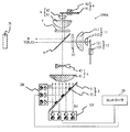
- FIG. 1 shows the configuration of the projector P as an image projection device on which any of the light source devices 100 (100A, 100A', 100B, 100C, 100D) of Examples 1 to 5 described later can be mounted.
- the projector P includes a light source device 100, an optical modulation unit (light modulation means) that modulates the light from the light source device 100, and a lens holding unit SU for holding a projection lens (projection optical system) PL. ..
- the projection lens (projection optical system) PL projects image light, which is light from the optical modulation unit, onto the screen (projected surface) SC.
- the optical modulation section is a general term for the light modulation section LP1 for red light, the light modulation section LP2 for green light, and the light modulation section LP3 for blue light, which will be described later.
- the light modulation units LP1 to LP3 all use a transmissive liquid crystal panel as a light modulation element.
- the lens holding portion SU may hold the projection lens PL detachably, or the projection lens PL may have a configuration in which the projection lens PL cannot be removed from the lens holding portion SU. Further, the holding unit SU may also have a function of shifting the held projection lens PL in a direction orthogonal to its optical axis.
- the projector P further includes an illumination optical system IS and a color separation composition system.
- the color separation / synthesis system is a general term for the dichroic mirrors DM1, DM2, mirrors M1, M2, M3, field lenses FL1, FL2, FL3, and relay lenses RL1, RL2, which will be described later.
- the red light R, green light G, and blue light B as the light emitted from the light source device 100 of each embodiment are incident on the dichroic mirror 1 via the illumination optical system IS.
- the dichroic mirror DM1 has a property of transmitting red light R and reflecting green light G and blue light B.
- the illumination optical system IS includes a fly-eye lens that divides light from a light source into a plurality of light beams, a polarization conversion unit that converts incident unpolarized light into linearly polarized light having a specific polarization direction, and the like, and makes the optical modulation unit uniform. Generates illumination light that illuminates with a uniform illumination distribution.
- the red light R transmitted through the dichroic mirror DM1 is incident on the light modulation unit LP1 for red light via the mirror M1 and the field lens FL1.
- the light modulation unit LP1 for red light is driven based on an image signal input from the outside to the projector to modulate the red light R.
- the modulated red light R is incident on the synthetic prism CP.
- the green light G reflected by the dichroic mirror DM1 is incident on the dichroic mirror DM2.
- the dichroic mirror DM2 has a property of reflecting green light G and transmitting blue light B.
- the green light G reflected by the dichroic mirror DM2 is incident on the light modulation unit LP2 for green light via the field lens FL2.
- the light modulation unit LP2 for green light is driven based on the above image signal to modulate the green light G.
- the modulated green light G is incident on the synthetic prism CP.
- the blue light B transmitted through the dichroic mirror DM1 is transmitted through the dichroic mirror DM2.
- the blue light B transmitted through the dichroic mirror DM2 is incident on the light modulation unit LP3 for blue light via the relay lens RL1, the mirror M2, the relay lens RL2, the mirror M3, and the field lens FL3.
- the light modulation unit LP3 for blue light is driven based on the above image signal to modulate the blue light B.
- the modulated blue light B is incident on the synthetic prism CP.
- the red light R, green light G, and blue light B incident on the synthetic prism CP are combined by the synthetic prism CP to become image light.
- the projection lens PL magnifies and projects the image light onto the screen SC. As a result, the projected image is displayed.
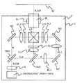
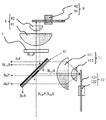
- FIG. 2 shows the configuration of the light source device 100A of the first embodiment.
- the light source device 100A includes a blue laser diode (LD) array 1B as a first light source that emits blue light B1 (wavelength 455 nm) as a first wavelength light and a first polarized light, and a second wavelength light and a second light source. It includes a blue LD array 2B as a second light source that emits blue light B2 (wavelength 455 nm) as the polarized light of 2.
- the blue light B2 has the same wavelength as the blue light B1, but the polarization direction is different by 90 degrees.
- the blue LD arrays 1B and 2B are composed of a plurality of GaN-based semiconductor LDs. However, this is only an example, and other semiconductor LDs may be used.
- blue light is light included in a band in which the wavelength of the maximum intensity or the full width at half maximum in the spectral intensity distribution of the light is 430 to 480 nm.
- green light is light included in a band in which the wavelength of the maximum intensity or the full width at half maximum in the spectral intensity distribution of the light is 500 to 580 nm.
- the light source device 100A further includes a photosynthesis unit (photosynthesis element) 3 having a transmission region for transmitting blue light B1 and a reflection region for reflecting blue light B2.
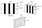
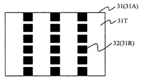
- the photosynthetic unit 3 has a plurality of photosynthetic units 3 on the surface 31A of the blue LD array 2B side (second light source side) of both surfaces of the transparent substrate (translucent substrate) 31. It has a configuration in which an aluminum reflective film 32 as a reflective portion is provided in a reflective region 31R which is a partial region.
- the transmission region is a plurality of regions 31T of the transparent substrate 31 on which the aluminum reflective film 32 is not provided. Further, as shown in FIG.
- an antireflection film is provided on the surface 31B of the blue LD array 1B side (first light source side) of both sides of the transparent substrate 31. This makes it possible to guide most of the blue light B1 from the blue LD array 1B to the photosynthesis unit 3.
- the photosynthesis unit 3 may have a configuration in which blue light B1 and B2 are synthesized by transmitting and reflecting them according to their polarization directions.
- the light source device 100A further includes a positive lens 41, a negative lens 42, and a compression optical system 4 that narrows the width of light from the photosynthetic unit 3.
- a compression optical system 4 that narrows the width of light from the photosynthetic unit 3.
- the light source device 100A further includes a polarization separating unit (optical element) 6, a ⁇ / 4 plate (first ⁇ / 4 plate as a polarization rotating means) 7, a condensing optical system 8 including condensing lenses 81 and 82, and diffusion. It includes a body unit (diffusion means) 9.
- the diffuser unit 9 is composed of a diffuser wheel 91 and a motor 92 for rotating the diffuser wheel 91.
- the condensing optical system 8 guides the light from the ⁇ / 4 plate 7 to the diffuser wheel 91 and parallelizes the light while taking in the light from the diffuser wheel 91 to guide the light to the ⁇ / 4 plate 7.
- the diffuser wheel 91 is provided with a diffusion layer for diffusing the light from the ⁇ / 4 plate 7 in a ring shape on the aluminum substrate.
- a diffusion layer for diffusing the light from the ⁇ / 4 plate 7 in a ring shape on the aluminum substrate.
- the light source device 100A further includes a ⁇ / 4 plate (second ⁇ / 4 plate) 10, a condensing optical system 11 including condensing lenses 111 and 112, and a phosphor unit (wavelength conversion means) 12.
- the phosphor unit 12 is composed of a phosphor wheel 121 and a motor 122 for rotating the phosphor wheel 121.
- the condensing optical system 11 guides the light from the ⁇ / 4 plate 10 to the phosphor wheel 121 and parallelizes the light while taking in the light from the phosphor wheel 121 to guide the light to the ⁇ / 4 plate 10.
- the phosphor wheel 121 is provided with a ring-shaped yellow phosphor layer on an aluminum substrate for wavelength-converting the light (excitation light) from the ⁇ / 4 plate 10.
- the motor 122 By rotating the phosphor wheel 121 by the motor 122, it is possible to prevent the yellow phosphor layer from being continuously irradiated with the light from the ⁇ / 4 plate 10 at one fixed place in the yellow phosphor layer and deteriorated. ..
- the light source device 100A includes a controller 20 as a control means.
- the controller 20 configured by a computer such as a CPU executes a process of controlling driving (that is, light emission amount) of the blue LD array 1B and the blue LD array 2B according to a computer program.
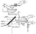
- FIG. 4 shows an optical path when the blue light B1 LD from the blue LD array 1B is guided to the illumination optical system IS via the diffuser unit 9.
- the blue light B1 LD from the blue LD array 1B is incident on the polarization separation membrane 612 of the polarization separation unit 6 together with the blue light B2 LD from the blue LD array 2B. Since the blue light B1 LD is P-polarized with respect to the polarization separation membrane 612, it is shown as B1 LD P in the figure, and since the blue light B2 LD is S-polarized, it is shown as B2 LD S.
- the polarizing separation membrane 612 is provided on the entire surfaces of both sides of the transparent substrate (translucent substrate) 611. However, the polarization separation membrane 612 may be provided on one side of the transparent substrate 611. This also applies to other examples described later.
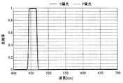
- FIG. 7 shows the characteristics of the polarizing separation membrane 612.
- Polarization splitting film 612 performs a polarization split for blue light B2 LD P from the blue light B1 LD S and blue LD array 2B from the blue LD array 1B, for the other wavelength light regardless of the polarization direction thereof It has the property of transmitting.
- the blue light B1 LDP transmitted through the polarization separation membrane 612 is converted into circularly polarized light by the ⁇ / 4 plate 7, condensed by the condensing optical system 8, and irradiated to the diffuser wheel 91.
- the blue light B1 LD diffused by the diffuser wheel 91 is converted into parallel light by the condensing optical system 8, converted into S-polarized light (polarized rotating light) by the ⁇ / 4 plate 7, and incident on the polarization separation film 612. Blue light B1 LD S became S polarized light is reflected by the polarization separating film 612 guided to the illumination optical system IS.
- FIG. 5 shows an optical path when the blue light B2 LD from the blue LD array 2B is guided to the illumination optical system IS via the phosphor unit 12.
- the blue light B2 LD S is a S-polarized light is reflected by the polarization splitting film 612.
- the reflected blue light B2 LD S is converted into circular polarization by the ⁇ / 4 plate 10, condensed by the condensing optical system 11, and incident on the yellow phosphor layer on the phosphor wheel 121.
- the yellow phosphor layer converts a part of blue light, which is excitation light, into yellow light (red light + green light) as fluorescent light (wavelength conversion light) having a wavelength longer than that of blue light.
- blue light B2 LDS blue light (hereinafter referred to as non-converted blue light) B2 F as unconverted light whose wavelength has not been converted by the yellow phosphor layer is parallelized by the condensing optical system 11 and ⁇ / It passes through the four plates 10 and is incident on the polarization separation film 612. Polarization direction of the non-converted blue light B2 F incident on the polarization separation film 612 is disturbed, S-polarized light component B2 F S of the non-converted blue light B2 F is returned to the blue LD array 2B is reflected by the polarization separating film 612 is, P-polarized light component B2 F P is guided to the illumination optical system iS is transmitted through the polarization splitting film 612.
- Figure 6 shows an optical path when the fluorescent light from the phosphor unit 12 (R F, G F) is guided to the illumination optical system IS.
- the green fluorescent light G F and the red fluorescence light R F is emitted from the yellow phosphor layer on the phosphor wheel 121.
- Fluorescent light incident on the polarization separation film 612 having the above-described characteristics (R F, G F) is guided to the illumination optical system IS is transmitted through the polarization separating film 612 regardless of the direction of polarization.
- the light source device 100A shown in FIG. 2 synthesizes the yellow light Y and the blue light B including the red light R and the green light G by the polarization separating unit 6, and directs the light to the illumination optical system IS as the emitted light. Exit.
- the luminance saturation of the phosphor contained in the yellow phosphor layer will be described.
- the light from the blue LD array 1B and the blue LD array 2B has a chromaticity of (0.14,0.04), and the fluorescent light has a chromaticity of (0.41, 0.57). It becomes.
- the amount of excitation light from the blue LD array 2B is increased, the amount of fluorescence light also increases, but the amount of light that returns as excitation light without being gradually converted to fluorescence increases. As a result, the amount of fluorescent light emitted from the phosphor decreases and shows a tendency to saturate.
- the amount of blue light emitted from the blue LD array 1B is constant, the amount of blue light emitted from the light source device 100A is constant. Therefore, when the amount of excitation light from the blue LD array 2B is increased and the amount of fluorescent light is increased, the chromaticity of the light emitted from the light source device 100A connects the chromaticity of the excitation light and the chromaticity of the fluorescent light from the chromaticity of the fluorescent light. It passes on the perpendicular and changes to approach the chromaticity of the excitation light.
- FIG. 8 shows the change in chromaticity of the light emitted from the light source device 100A with respect to the change in the amount of excitation light (B2 LD ) from the blue LD array 2B.
- the maximum value of the excitation light amount on the horizontal axis is 1 (150 W in this embodiment)
- the y value of the light emitted from the light source device 100A is shown on the vertical axis.
- the amount of excitation light is halved, the amount of fluorescent light decreases, so that the y value, which is the chromaticity of the light emitted from the light source device 100A, decreases from 0.38 to 0.29.
- FIG. 8 shows the change in chromaticity of the light emitted from the light source device 100A with respect to the change in the amount of light of the blue LD array 1B.
- the horizontal axis shows the maximum value of the amount of blue light from the blue LD array 1B as 1 (30 W in this embodiment), and the vertical axis shows the y value of the light emitted from the light source device 100A.
- the y value which is the chromaticity of the light emitted from the light source device 100A, increases from 0.38 to 0.46.
- the controller 20 records the change in chromaticity of the light emitted from the light source device 100A while changing the amount of light from the blue LD array 1B and the blue LD array 2B. For example, when the amount of light from the blue LD array 2B is changed to 1, 0.75, 0.5, the y values are recorded as 0.38, 0.34, 0.29, and the relationship is recorded as a lookup table. It is saved in the memory in the projector P. Similarly, when the amount of light from the blue LD array 1B is changed to 1, 0.75, 0.5, the y values are recorded as 0.30, 0.41, 0.46, and the relationship is recorded in the lookup table. It is saved in the above memory as.
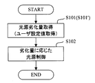
- the controller 20 first acquires the amount of deterioration of the blue LD array 1B and the blue LD array 2B (step S101).
- the amount of deterioration can be obtained by measuring the amount of light from each blue LD array using an optical sensor or detecting the temperature of each blue LD array using a temperature sensor.
- the amount of deterioration may be obtained from the history information of the lighting time of each blue LD array. Then, the controller 20 controls the driving of the blue LD arrays 1B and 2B as follows according to the amount of change in the amount of light from each blue LD array acquired from the deterioration amount (step S102).
- the controller 20 increases the drive current of the blue LD array 1B so as to reduce the amount of light of the blue LD array 1B by 29% from the amount of light at the initial use of the projector P. As a result, it is possible to suppress a change in the color of the light emitted from the light source device 100A.
- the user of the projector P can also set the amount of light emitted from the light source device 100A (hereinafter referred to as the brightness of the light source).
- the controller 20 acquires the brightness setting value (user setting value regarding the amount of emitted light) of the light source set by the user by the setting operation for the projector P, and the blue LD array 1B, according to the brightness setting value.
- the amount of light of at least one of 2 is changed (steps S101', 102 in FIG. 27).
- the controller 20 sets the amount of light emitted from the phosphor to 50% by setting the amount of light of the blue LD array 2B to 50%.
- the y value of the light emitted from the light source device 100A becomes 0.34, which is 0.04 lower than when the brightness of the light source is 100%. Assumed from the lookup table.
- the controller 20 increases the drive current of the blue LD array 1B so as to reduce the amount of light of the blue LD array 1B by 29%.
- the brightness of the light source set by the user can be obtained, and the change in the color of the light emitted from the light source device 100A can be suppressed.
- the amount of change in the amount of light emitted from the blue LD arrays 1B and 2B is different from that of the blue LD arrays 1B and 2B according to the change in the amount of light emitted from at least one of the blue LD arrays 1B and 2B.
- the light emission amount of at least one of the blue LD arrays 1B and 2B is controlled so that the ratio of the light emission amounts of the blue LD arrays 1B and 2B changes.
- the light source device 100A'of this embodiment has the same configuration as that of the first embodiment. That is, the light source device 100A'has a blue LD array 1B as a first light source that emits blue light B1 (wavelength 455 nm) as a first wavelength light and a first polarized light, and a second wavelength light and a second. It is provided with a blue LD array 2B as a second light source that emits blue light B2 (wavelength 465 nm) as polarized light.
- the blue light B2 has a different wavelength from the blue light B1 and the polarization direction is different by 90 degrees.
- the optical path of the blue light B1, the optical path of the blue light B2, and the optical path of the fluorescent light are as described with reference to FIGS. 4, 5 and 6, respectively, in the first embodiment.
- FIG. 9 shows the spectral intensity distribution of the light emitted from the light source device 100A'.
- the horizontal axis shows the wavelength and the vertical axis shows the light intensity.
- the wavelength of the blue LD array 1B is 465 nm, and the blue light of this wavelength is close to the chromaticity of blue in the sRGB color gamut. Since blue light of this wavelength is mainly projected from the light source device 100A', the tint of blue can be improved.
- the wavelength of the blue LD array 2B is 455 nm, the hue is inferior to that of the blue LD array 1B, but the excitation light irradiating the YAG phosphor used in this example has high excitation efficiency. Therefore, it is possible to perform fluorescence conversion more efficiently than in Example 1.
- the luminance saturation of the phosphor contained in the yellow phosphor layer becomes a problem.
- the light from the blue LD array 1B and the blue LD array 2B has a chromaticity of (0.13, 0.06), and the fluorescent light has a chromaticity of (0.41, 0.57). ..
- the amount of excitation light from the blue LD array 2B is increased, the amount of fluorescence light also increases, but the amount of light that returns as excitation light without gradual fluorescence conversion increases. As a result, the amount of fluorescent light emitted from the phosphor decreases and shows a tendency to saturate.
- the amount of blue light emitted from the blue LD array 1B is constant, the amount of blue light emitted from the light source device 100A'is constant. Therefore, when the amount of excitation light from the blue LD array 2B is increased and the amount of fluorescence light is increased, the chromaticity of the light emitted from the light source device 100A'is the chromaticity of the excitation light and the fluorescence light from the chromaticity of the fluorescence light. It passes on the line connecting the two and changes so as to approach the chromaticity of the excitation light.
- the change in the excitation light amount (B2 LD ) from the blue LD array 2B and the change in the chromaticity emitted from the light source device 100A'with respect to the change in the blue light amount (B1 LD ) of the blue LD array 1B are shown in FIG. As explained using.
- the controller 20 looks up the relationship between the amount of light and the chromaticity of the light emitted from the light source device 100A'while changing the amount of light from the blue LD arrays 1B and 2 as described in the first embodiment. Save to memory as a table.
- the amount of deterioration of the blue LD arrays 1B and 2 is acquired, the amount of increase in the amount of light of the blue LD array 1B corresponding to the decrease in the amount of light of the blue LD array 2B is obtained from the lookup table, and the drive current of the blue LD array 1B is increased. Let me.
- the amount of light of at least one of the blue LD arrays 1B and 2 may be changed according to the brightness setting value of the light source set by the user of the projector P.
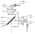
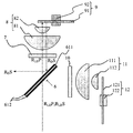
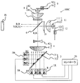
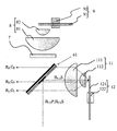
- FIG. 10 shows the configuration of the light source device 100B of the third embodiment.
- the light source device 100B includes a red LD array 1R as a first light source that emits red light R (wavelength 640 nm) as a first wavelength light and a first polarized light, and a second wavelength light and a second polarized light.
- a blue LD array 2B as a second light source that emits blue light B (wavelength 455 nm) is provided.
- the blue light B has a different wavelength from the red light R, and the polarization direction is different by 90 degrees.
- the blue LD array 2B is composed of a plurality of GaN-based semiconductor LDs
- the red LD array 1R is composed of a plurality of GaAs-based semiconductor LDs.
- red light refers to light included in a band in which the wavelength of maximum intensity or the full width at half maximum in the spectral distribution of the light is 600 to 750 nm.
- the light source device 100B further includes a photosynthetic unit 3 having a transmission region for transmitting red light R and a reflection region for reflecting blue light B.
- the photosynthesis unit 3 has the same configuration as that shown in FIGS. 3A to 3C, and most of the red light R from the red LD array 1R is guided to the photosynthesis unit 3.
- the photosynthesis unit 3 may have a configuration in which red light R and blue light B are combined by transmitting and reflecting them according to their polarization directions.
- the light source device 100B further includes a compression optical system 4 that narrows the width of the light from the positive lens 41, the negative lens 42, and the photosynthetic unit 3 as in the first embodiment.
- the light source device 100B further includes a polarizing separation unit 6, a ⁇ / 4 plate 7, a condensing optical system 8 including a condensing lens 81 and 82, a diffuser unit 9, a ⁇ / 4 plate 10, and a collection.
- It includes a condensing optical system 11 including optical lenses 111 and 112 and a phosphor unit 12.
- the configurations of the diffuser unit 9 and the phosphor unit 12 are the same as those in the first embodiment.
- the light source device 100B is also provided with a controller 20, and the controller 20 executes a process of controlling the drive (that is, the amount of light emission) of the red LD array 1R and the blue LD array 2B according to a computer program.
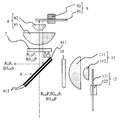
- FIG. 11 shows an optical path when the red light R LD from the red LD array 1R is guided to the illumination optical system IS via the diffuser unit 9.
- the red light R LD from the red LD array 1R is incident on the polarization separation membrane 612 of the polarization separation unit 6 together with the blue light B LD from the blue LD array 2B. Since the red light R LD is P-polarized with respect to the polarization separation membrane 612, it is indicated as R LD P in the figure, and the blue light B LD is indicated as B LD S because it is S-polarized.
- the polarizing separation membrane 612 is provided on the entire surfaces of both sides of the transparent substrate 611.
- FIG. 14 shows the characteristics of the polarizing separation membrane 612.
- Polarization splitting film 612 performs polarization separation for the blue light B LD P from the red light R LD S and blue LD array 2B from the red LD array 1R, for the other wavelength light regardless of the polarization direction thereof It has the property of being transparent.
- the red light R LDP transmitted through the polarization separation membrane 612 is converted into circularly polarized light by the ⁇ / 4 plate 7, condensed by the condensing optical system 8, and irradiated to the diffuser wheel 91.
- the red light R LD diffused by the diffuser wheel 91 is converted into parallel light by the condensing optical system 8, converted into S-polarized light (polarized rotating light) by the ⁇ / 4 plate 7, and incident on the polarization separation film 612.
- the red light R LD S became S polarized light is reflected by the polarization separating film 612 guided to the illumination optical system IS.
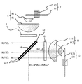
- FIG. 12 shows an optical path when the blue light B LD from the blue LD array 2B is guided to the illumination optical system IS via the phosphor unit 12.
- the blue light BLDS which is S-polarized light
- the reflected blue light BLDS is converted into circular polarization by the ⁇ / 4 plate 10, condensed by the focusing optical system 11, and incident on the yellow phosphor layer on the phosphor wheel 121.
- the yellow phosphor layer converts a part of blue light, which is excitation light, into yellow light (red light + green light) as fluorescent light having a wavelength longer than that of blue light.
- the unconverted blue light BF that was not wavelength-converted by the yellow phosphor layer is converted into parallel light by the condensing optical system 11 and passes through the ⁇ / 4 plate 10 to the polarization separation membrane 612. Incident. Polarization direction of the non-converted blue light B2 F incident on the polarization separation film 612 is disturbed, S-polarized light component B F S of the non-converted blue light B2 F is returned to the blue LD array 2B is reflected by the polarization separating film 612 is, P-polarized light component B F P is guided to the illumination optical system iS is transmitted through the polarization splitting film 612.
- Figure 13 shows an optical path when the fluorescent light from the phosphor unit 12 (R F, G F) is guided to the illumination optical system IS.
- the fluorescence light including the green fluorescent light G F and the red fluorescence light R F is emitted from the yellow phosphor layer on the phosphor wheel 121.
- Green fluorescent light G F incident on the polarization separation film 612 having the above properties is guided to the illumination optical system IS is transmitted through the polarization separating film 612 regardless of the direction of polarization.
- the light source device 100B shown in FIG. 10 synthesizes the yellow light Y and the blue light B including the red light R and the green light G by the polarization separating unit 6, and directs the light to the illumination optical system IS as the emitted light. Exit.
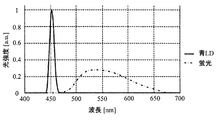
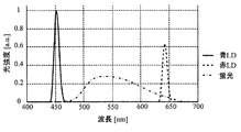
- FIG. 15 shows the spectral intensity distribution of the light emitted from the light source device 100B.
- the horizontal axis shows the wavelength and the vertical axis shows the light intensity.
- the wavelength of the red LD array 1R is 640 nm, and the red light of this wavelength is close to the chromaticity of red in the sRGB color gamut. Since red light of this wavelength is mainly projected from the light source device 100B, the tint of red can be improved.
- the excitation light for irradiating the YAG phosphor used in this example has high excitation efficiency. Therefore, it is possible to perform fluorescence conversion more efficiently than in Example 1.
- the light source device 100B of the present embodiment emits red light from the red LD array in addition to the blue light from the blue LD array and the fluorescent light from the yellow phosphor layer that can be emitted by the conventional light source device. be able to. That is, in the projector P equipped with the light source device 100B, as the red light used for image projection, as shown in FIG. 15, in addition to the red light contained in the fluorescent light from the yellow phosphor layer, the red light from the red LD array Light can also be used. As a result, the projector P using the light source device 100B of this embodiment can display a projected image brighter than that of the conventional projector.
- the number of blue LDs it is conceivable to increase the number of blue LDs to increase the amount of blue light incident on the yellow phosphor layer in order to increase the amount of red light contained in the fluorescent light.
- the brightness of the phosphor is increased because the amount of red light is increased by using the red LD array instead of increasing the amount of red light contained in the fluorescent light. It is possible to display a projected image brighter than before without being limited by the limit due to the saturation characteristic.
- the amount of red light is insufficient. Therefore, when projecting an all-white image whose entire surface is white, the amount of green light is adjusted to match the small amount of red light. It was necessary to reduce the amount of blue light and adjust the balance of white. More specifically, when the light modulation unit is a reflective type, the reflectance of the light modulation unit for both color light is lowered for green light and blue light to reduce the amount of green light and the amount of blue light guided to the screen. I needed it. As a result, the brightness of the all-white image is reduced in the conventional projector.
- the light source device 100B of the present embodiment since the amount of red light is increased by using the red light from the red LD array, it is not necessary to reduce the amount of green light and the amount of blue light in the light modulation unit. It is possible to suppress a decrease in brightness.
- a red LD that emits red light having a wavelength longer than 640 nm is also provided to provide a wider color than before. It is possible to reproduce the area.
- the light source device 100B of the present embodiment since the light from the two light sources is combined by one photosynthetic unit, it is possible to obtain the effect of improving the brightness while suppressing the increase in size of the light source device.
- the luminance saturation of the phosphor contained in the yellow phosphor layer becomes a problem.
- the light from the blue LD array 2B has a chromaticity of (0.14,0.04), and the fluorescent light has a chromaticity of (0.41, 0.57).
- the light from the red LD array 1R has a chromaticity of (0.72, 0.28).
- Example 1 As described in Example 1, as the amount of excitation light from the blue LD array 2B is increased, the amount of fluorescence light also increases, but the amount of light that returns as excitation light without gradual fluorescence conversion increases. As a result, the amount of fluorescent light emitted from the phosphor decreases and shows a tendency to saturate. Therefore, when the amount of excitation light from the blue LD array 2B is increased, both the amount of fluorescence light and the amount of excitation light that has not been fluorescently converted increase, but the amount of excitation light relatively increases due to the luminance saturation characteristics of the phosphor.
- the chromaticity of the light emitted from the light source device 100B changes from the chromaticity of the fluorescent light to approach the chromaticity of the excitation light through the line connecting the chromaticity of the excitation light and the fluorescence light. For this reason, conventionally, when projecting an all-white image, it has been necessary to balance the fluorescence light and the excitation light and keep the chromaticity constant. More specifically, when the light modulation unit is a reflective type, the reflectance of the excessive color light modulation unit is lowered to reduce the amount of light guided to the screen to keep the chromaticity constant. I had to make some adjustments.
- the optical modulation unit makes adjustments to keep the chromaticity of all white constant, but also the chromaticity of the single red color must be kept constant.
- the gamut changes. This is because the light emitted from the light source device 100B of this embodiment includes red fluorescent light and red light from the red LD array 1R, and the chromaticity is determined by the composite spectrum of these, so that the red fluorescent light This is because the chromaticity changes when the mixing ratio of the red light from the red LD array 1R and the red light is different. Therefore, in this embodiment, the amount of red light from the red LD array 1R is adjusted so that the mixing ratio of the red fluorescent light and the red light from the red LD array 1R is equal.
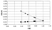
- FIG. 16 shows the change in chromaticity of the light emitted from the light source device 100B with respect to the change in the amount of excitation light ( BLD ) from the blue LD array 2B.
- the maximum value of the excitation light amount on the horizontal axis is 1 (150 W in this embodiment), and the y value of the light emitted from the light source device 100B is shown on the vertical axis.
- the amount of excitation light when the amount of excitation light is halved, the amount of light that returns as excitation light without fluorescence conversion decreases and the amount of fluorescence light increases, so this is the chromaticity of the light emitted from the light source device 100B.
- the x value increases from 0.314 to 0.343.
- FIG. 16 shows the change in chromaticity of the light emitted from the light source device 100B with respect to the change in the amount of red light from the red LD array 1R.
- the maximum value of the amount of red light is 1 (15 W in this embodiment)
- the vertical axis shows the x value of the light emitted from the light source device 100B.
- the x value which is the chromaticity of the light emitted from the light source device 100B, decreases from 0.314 to 0.310.
- the controller 20 records the change in chromaticity of the light emitted from the light source device 100B while changing the amount of light from the red LD array 1R and the blue LD array 2B. For example, when the amount of light from the blue LD array 2B is changed to 1, 0.75, 0.5, the x values are recorded as 0.314, 0.328, 0.343, and the relationship is recorded as a lookup table. It is saved in the memory in the projector P.
- the controller 20 first acquires the deterioration amounts of the red LD array 1R and the blue LD array 2B (step S101), and the red color and the red color acquired from the deterioration amounts are obtained.
- the drive of the red and blue LD arrays 1R and 2B is controlled according to the amount of change in the light emission amount of the blue LD arrays 1R and 2B (step S102).
- the method for obtaining the amount of deterioration is as described in Example 1.
- the controller 20 increases the drive current of the red LD array 1R so as to reduce the light intensity of the red LD array 1R by 45% from the initial light intensity of the projector P (step S102). As a result, it is possible to suppress a change in the color of the light emitted from the light source device 100B.
- the controller 20 acquires the brightness setting value of the light source set by the user by the setting operation for the projector P, and changes the light amount of the blue LD array 2B according to the brightness setting value (FIG. 27). Steps S101', S102).
- the controller 20 reduces the amount of light of the blue LD array 2B so that the amount of light emitted from the light source device 100B is 55% of the maximum output.
- the controller 20 sets the amount of light emitted from the phosphor to 55% by setting the amount of light of the blue LD array 2B to 50%.
- the x value of the light emitted from the light source device 100B becomes 0.343, which is 0.029 lower than when the brightness of the light source is 100%. Assumed from the lookup table.
- the controller 20 reduces the drive current of the red LD array 1R so as to reduce the amount of light of the red LD array 1R by 45%.
- the brightness of the light source set by the user can be obtained, and the change in the color of the light emitted from the light source device 100B can be suppressed.
- the amount of change in the amount of light emitted from the red and blue LD arrays 1R and 2B changes according to the change in the amount of light emitted from at least one of the red and blue LD arrays 1R and 2B.
- the emission amount of at least one of the red and blue LD arrays 1R and 2B is controlled so as to be different from each other or so that the ratio of the emission amounts of the red and blue LD arrays 1R and 2B is changed.
- the red light from the red LD array 1R is transmitted through the photosynthesis unit 3, and the blue light from the blue LD array 2B is reflected by the photosynthesis unit 3.
- the light amount loss in transmission is smaller. Therefore, as in the light source device 100B, by configuring the red light from the red LD array 1R to pass through the photosynthetic unit 3, it is possible to supplement more of the red light that was conventionally lacking as described above. It becomes.
- the shortage of red light is further reduced by making the number of red LDs contained in the red LD array 1 larger than the number of blue LDs contained in the blue LD array 2B. It becomes possible.
- the photosynthesis unit 3 it is desirable to configure the photosynthesis unit 3 so that the area of the transmission region 31T is larger than the area of the reflection region 31R. In other words, it is desirable that the width W1 of the transmission region 31T is wider than the width W2 of the reflection region 31R. According to this configuration, even if the arrangement position of the red LD array 1R deviates from the normal position due to a mounting error or the like, it is possible to suppress that the light from the red LD array 1R is blocked by the reflecting unit 32. Become.
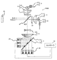
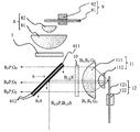
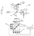
- FIG. 17 shows the configuration of the light source device 100C of the fourth embodiment.
- the light source device 100C includes a red LD array 1R as a first light source that emits red light R (wavelength 640 nm) as a first wavelength light and a first polarized light, and a second wavelength light and a second polarized light.
- a blue LD array 2B as a second light source that emits blue light B2 (wavelength 455 nm)
- a third light source that emits blue light B3 (wavelength 465 nm) as a third wavelength light and a third polarized light.
- the blue LD array 3B is provided.
- the wavelength of the blue light B3 is different from that of the blue light B2.
- the red light R and the blue light B3 have the same polarization direction as each other, and the polarization direction is 90 degrees different from that of the blue light B2.
- the blue LD array 3B which is the third light source, should be regarded as a first light source different from the red LD array 1R, which is the first light source, with respect to the blue LD array 2B, which is the second light source. Can be done.
- the light source device 100C further includes a photosynthetic unit 3 having a transmission region for transmitting red light R and a reflection region for reflecting blue light B2 and B3.
- the photosynthesis unit 3 has the same configuration as the photosynthesis unit 3 described with reference to FIGS. 3A to 3C in Example 1. That is, it has a configuration in which an aluminum reflective film 32 as a reflective portion is provided in a reflective region 31R which is a plurality of partial regions on the surface 31A on the blue LD array 2B side (second light source side) of both sides of the transparent substrate 31. ..
- the transmission region is a plurality of regions 31T of the transparent substrate 31 on which the aluminum reflective film 32 is not provided.
- antireflection films are provided on the surfaces 31B of the red LD array 1R and the blue LD array 3B side (first and third light source sides) of both sides of the transparent substrate 31. As a result, most of the red light R and the blue light B3 from the red LD array 1R and the blue LD array 3B can be guided to the photosynthesis unit 3.
- the photosynthesis unit 3 may have a configuration in which red light R, blue light B3, and blue light B2 are combined by transmitting and reflecting them according to their polarization directions.
- the light source device 100C further includes a compression optical system 4 that narrows the width of the light from the positive lens 41, the negative lens 42, and the photosynthetic unit 3 as in the first embodiment.
- the light source device 100C further includes a polarizing separation unit 6, a ⁇ / 4 plate 7, a condensing optical system 8 including a condensing lens 81 and 82, a diffuser unit 9, a ⁇ / 4 plate 10, and a collection.
- It includes a condensing optical system 11 including optical lenses 111 and 112 and a phosphor unit 12.
- the configurations of the diffuser unit 9 and the phosphor unit 12 are the same as those in the first embodiment.
- the light source device 100C is also provided with a controller 20, and the controller 20 executes a process of controlling driving (that is, light emission amount) of the red LD array 1R, the blue LD array 2B, and the blue LD array 3B according to a computer program. To do.
- FIG. 18 shows an optical path when the red light R LD from the red LD array 1R and the blue light B3 LD from the blue LD array 3B are guided to the illumination optical system IS via the diffuser unit 9.
- the red light R LD from the red LD array 1R and the blue light B3 LD from the blue LD array 3B are incident on the polarization separation film 612 of the polarization separation unit 6 together with the blue light B2 LD from the blue LD array 2B. Since the red light R LD and the blue light B3 LD are P-polarized with respect to the polarization separation membrane 612, they are shown as R LD P and B3 LD P in the figure, respectively, and the blue light B2 LD is S-polarized and therefore B2 LD. It is shown as S.
- the polarizing separation membrane 612 is provided on the entire surfaces of both sides of the transparent substrate 611.
- Polarization separation film 612 in this embodiment transmits the red light R LD P and blue light B3 LD P, reflects the blue light B3 LD P and blue light B2 LD S.
- the P-polarized red light R LD P and blue light B3 LD P transmitted through the polarization separation membrane 612 are converted into circularly polarized light by the ⁇ / 4 plate 7, condensed by the condensing optical system 8, and irradiated to the diffuser wheel 91. Will be done.
- the red light R LD and blue light B3 LD diffused by the diffuser wheel 91 are parallelized by the condensing optical system 8 and converted into S-polarized light (polarized rotating light) by the ⁇ / 4 plate 7, and are polarized separation membranes. It is incident on 612.
- the red light R LD S and blue light B3 LD S became S polarized light, respectively, are reflected by the polarization separating film 612 guided to the illumination optical system IS.
- FIG. 19 shows an optical path when the blue light B2 LD from the blue LD array 2 is guided to the illumination optical system IS via the phosphor unit 12.
- the blue light B2 LD S is a S-polarized light is reflected by the polarization splitting film 612.
- the reflected blue light B2 LD S is converted into circular polarization by the ⁇ / 4 plate 10, condensed by the condensing optical system 11, and incident on the yellow phosphor layer on the phosphor wheel 121.
- the yellow phosphor layer converts a part of blue light, which is excitation light, into yellow light (red light + green light) as fluorescent light having a wavelength longer than that of blue light.
- the unconverted blue light B2 F whose wavelength was not converted by the yellow phosphor layer is converted into parallel light by the condensing optical system 11 and passes through the ⁇ / 4 plate 10 to the polarization separation membrane 612. Incident. Polarization direction of the non-converted blue light B2 F incident on the polarization separation film 612 is disturbed, S-polarized light component B2 F S of the non-converted blue light B2 F is returned to the blue LD array 2B is reflected by the polarization separating film 612 is, P-polarized light component B2 F P is guided to the illumination optical system iS is transmitted through the polarization splitting film 612.
- Figure 20 shows an optical path when the fluorescent light from the phosphor unit 12 (R F, G F) is guided to the illumination optical system IS.
- the green fluorescent light G F and the red fluorescence light R F is emitted from the yellow phosphor layer on the phosphor wheel 121.
- Fluorescent light incident on the polarization separation film 612 having the above-described characteristics (R F, G F) is guided to the illumination optical system IS is transmitted through the polarization separating film 612 regardless of the direction of polarization.
- the light source device 100C shown in FIG. 17 synthesizes the yellow light Y and the blue light B including the red light R and the green light G by the polarization separating unit 6, and directs the light to the illumination optical system IS as the emitted light. Exit.
- the luminance saturation of the phosphor contained in the yellow phosphor layer becomes a problem.
- the light from the blue LD array 2B has a chromaticity of (0.14,0.04)
- the light from the blue LD array 3B has a chromaticity of (0.13,0.06).
- the fluorescent light has a chromaticity of (0.41, 0.57)
- the light from the red LD array 1R has a chromaticity of (0.72, 0.28).
- Example 1 As described in Example 1, as the amount of excitation light from the blue LD array 2B is increased, the amount of fluorescence light also increases, but the amount of light that returns as excitation light without gradual fluorescence conversion increases. Therefore, the amount of light emitted from the phosphor decreases and shows a tendency to saturate.
- the amount of light from the blue LD array 3 is constant, the amount of blue light emitted from the light source device is constant. Therefore, as the amount of excitation light from the blue LD array 2B is increased, the amount of fluorescent light increases. Therefore, the chromaticity of the light emitted from the light source device 100C is determined from the chromaticity of the fluorescent light to the chromaticity of the excitation light and the fluorescent light. It changes so as to approach the chromaticity of the excitation light through the line connecting the two.
- the change in the chromaticity (y value) of the light emitted from the light source device 100C with respect to the change in the amount of excitation light (B2 LD ) from the blue LD array 2B is as shown by ⁇ in FIG.
- the amount of excitation light is halved, the amount of fluorescent light decreases, so that the y value, which is the chromaticity of the light emitted from the light source device 100C, decreases from 0.38 to 0.29.
- the amount of light from the blue LD array 3B is reduced. If the amount of light from the other blue LD array 2B is constant, the amount of fluorescent light from the phosphor is constant. Therefore, when the amount of light from the blue LD array 3B decreases, the chromaticity of the light emitted from the light source device 100C approaches the chromaticity of the fluorescent light through the line connecting the chromaticity of the excitation light and the fluorescence light. Change. In this embodiment, the change in the chromaticity (y value) of the light emitted from the light source device 100C with respect to the change in the amount of excitation light (B3 LD ) from the blue LD array 3B is as shown by (3) in FIG.
- the y value which is the chromaticity of the light emitted from the light source device 100C, is It increases from 0.38 to 0.46.
- the controller 20 records the change in the chromaticity of the light emitted from the light source device 100C while changing the amount of light from the blue LD array 2B and the blue LD array 3B. For example, when the amount of light from the blue LD array 2B is changed to 1, 0.75, 0.5, the y values are recorded as 0.38, 0.34, 0.29, and the relationship is recorded as a lookup table. It is saved in the memory in the projector P. Similarly, when the amount of light from the blue LD array 3B is changed to 1, 0.75, 0.5, the y values are recorded as 0.30, 0.41, 0.46, and the relationship is recorded in the lookup table. It is saved in the above memory as.
- the controller 20 first acquires the deterioration amounts of the blue LD array 2B and the blue LD array 3B (step S101), and the blue LD acquired from the deterioration amounts.
- the drive of the blue LD arrays 2B and 3B is controlled according to the amount of change in the amount of light emitted from the arrays 2B and 3B (step S102).
- the method for obtaining the amount of deterioration is as described in Example 1.
- the controller 20 increases the drive current of the blue LD array 3B so as to reduce the light intensity of the blue LD array 3B by 29% from the initial light intensity of the projector P.
- the controller 20 adjusts the amount of red light from the red LD array 1R so that the mixing ratio of the red fluorescent light and the red light from the red LD array 1R becomes equal as in the third embodiment. ..
- the controller 20 records the change in chromaticity of the light emitted from the light source device 100C while changing the amount of light of the red LD array 1R and the blue LD array 2B. Then, the change in the amount of red light emitted from the light source device 100C corresponding to the change in chromaticity is calculated, and the amount of red light in the red LD array 1R that substantially matches the change in the amount of red light is stored in the memory as a lookup table. ..
- the x values are recorded as 0.314, 0.328, 0.343, and the relationship is recorded as a lookup table. It is saved in the memory in the projector P.
- the y values are recorded as 0.378, 0.403, 0.423, and the relationship is recorded in the lookup table. It is saved in the above memory as.
- the controller 20 first acquires the deterioration amount of the red LD array 1R and the blue LD array 2B (step S101), and the red color and the red color acquired from the deterioration amount are obtained.
- the drive of the red and blue LD arrays 1R and 2B is controlled according to the amount of change in the light emission amount of the blue LD arrays 1R and 2B (step S102).
- the method for obtaining the amount of deterioration is as described in Example 1.
- the controller 20 reduces the drive current of the red LD array 1 so that the amount of red light from the red LD array 1R is reduced by 45% from the amount of light at the initial use of the projector P. As a result, it is possible to suppress a change in the color of the light emitted from the light source device 100C.
- the controller 20 acquires the brightness setting value of the light source set by the user by the setting operation for the projector P, and sets the amount of light of at least one of the blue LD arrays 2B and 3B according to the brightness setting value. Change ((steps S101', 102 in FIG. 27)).
- the controller 20 sets the amount of light emitted from the phosphor to 50% by setting the amount of light of the blue LD array 2B to 50%.
- the y value of the light emitted from the light source device 100A becomes 0.34, which is 0.04 lower than when the brightness of the light source is 100%. Assumed from the lookup table.
- the controller 20 increases the drive current of the red LD array 1R so as to reduce the amount of red light from the red LD array 1R by 29%. As a result, the brightness of the light source set by the user can be obtained, and the change in the color of the light emitted from the light source device 100C can be suppressed.
- the controller 20 in the present embodiment emits light from the red and blue LD arrays 1R, 2B and 3B according to a change in the light emission amount of at least one of the red and blue LD arrays 1R, 2B and 3B.
- the amount of light emitted from at least one of the red and blue LD arrays 1R, 2B, 3B is controlled so that the amount of change in the red and blue LD arrays 1R, 2B, 3B changes. ..
- the change in the color of the light emitted from the light source device 100C can be suppressed.
- Examples 1 to 4 the configuration using the ⁇ / 4 plate 10 is shown, but the ⁇ / 4 plate 10 may not be used.
- FIG. 21 shows the configuration of the light source device 100D of the fifth embodiment.
- the light source device 100D of the present embodiment has a polarization separation unit 61 having a configuration different from that of the polarization separation unit 6 provided in the light source device 100 of the third embodiment, and ⁇ / provided in the light source device 100 of the third embodiment. It does not have 4 plates 10. Further, the light source device 100D of the present embodiment includes a ⁇ / 2 plate 5 which is not provided in the light source device 100 of the third embodiment.
- the light source device 100D is also provided with a controller 20, and the controller 20 executes a process of controlling driving (that is, light emission amount) of the red LD array 1R and the blue LD array 2B according to a computer program.
- 22 (a), (b), and (c) show the configuration of the polarization separating unit 61.
- the polarization separation unit 61 includes a transparent substrate (translucent substrate) 611 and a polarization separation membrane (hereinafter, incident side polarization separation) provided on the incident side surface of the transparent substrate 611.
- the polarizing separation films 612a and 612b perform polarization separation for blue light from the blue LD array 2B and red light from the red LD array 1R, and polarize light of other wavelengths. It has the property of transmitting light regardless of the direction.
- the polarization separation film 612 was provided on the entire surface of the transparent substrate 611 on the incident side.
- the incident side polarizing separation film 612a is provided on a part of the incident side surface of the transparent substrate 611.
- the phase difference imparting portion 613 is provided in a region (around the incident side polarizing separation membrane 612) different from the region in which the incident side polarizing separation membrane 612a is provided.
- the phase difference imparting unit 613 has a characteristic of converting the S-polarized light incident therein into P-polarized light and converting the P-polarized light into S-polarized light (that is, rotating the polarization direction by 90 °).
- the light emitting side polarizing separation film 612b is provided on the entire surface of the transparent substrate 611 on the light emitting side.
- the incident side polarizing separation membrane 612a is arranged so that most of the light from the compression optical system 4 is incident.
- the area of the incident side polarization separation membrane 612a is larger than the area where the light from the compression optical system 4 is incident on the incident side surface of the polarization separation unit 61. It is getting wider.
- FIG. 23 shows an optical path when the blue light B LD from the blue LD array 2B is guided to the illumination optical system IS via the diffuser unit 9 and the phosphor unit 12.
- a part of the blue light BLDS as S-polarized light from the blue LD array 2B is incident on the ⁇ / 2 plate 5 and converted into blue light BLDP P as P-polarized light.
- the blue light BLDP P which is P-polarized light, passes through the incident-side and outgoing-side polarized light separation films 612a and 612b, is converted into circularly polarized light by the ⁇ / 4 plate 7, and is condensed by the condensing optical system 8 to be a diffuser.
- the diffuser wheel 91 of the unit 9 is irradiated.
- the blue light B LD diffused by diffuser wheel 91 is collimated by the focusing optical system 8, lambda / 4 S-polarized light by the plate 7 (polarization rotation light) B LD S is converted into that in the exit side polarization separation film It is reflected by 612b and guided to the illumination optical system IS.
- the blue light BLDS which is S-polarized light that has not been converted into P-polarized light by the ⁇ / 2 plate 5
- the incident-side polarization separation membrane 612a of the polarization separation unit 61 is reflected by the incident-side polarization separation membrane 612a of the polarization separation unit 61 and guided to the phosphor unit 12 for fluorescence. It is incident on the yellow phosphor layer on the body wheel 121.
- a part of the blue light BLDS incident on the yellow phosphor layer is wavelength-converted to fluorescent light.
- the unconverted blue light BF which has not been wavelength-converted by the yellow phosphor layer, is converted into parallel light by the condensing optical system 11 and incident on the polarization separation unit 61.
- the polarization direction of the unconverted blue light incident on the polarization separation unit 61 is disturbed.
- Some of the S-polarized component B F S of the non-converted blue light B F is returned to the blue LD array 2B is reflected by the incident-side polarization separation film 612a.
- S-polarized light component B F S incident on the phase difference providing unit 613 is guided to the illumination optical system IS transmitted through the exit side polarization separation film 612b is converted into blue light B F P as P-polarized light.
- FIG. 24 shows an optical path when the red light R LD from the red LD array 1R is guided to the illumination optical system IS via the diffuser unit 9 and the phosphor unit 12.
- Red LD red light R LD red light is to be converted P-polarized light into P R LD P as part of the red light R LD S as S polarized light from the array 1R is incident to the lambda / 2 plate 5
- the body wheel 91 is irradiated.
- the red light R LD diffused by the diffuser wheel 91 is converted into parallel light by the condensing optical system 8 and converted into S polarized light (polarized rotating light) R LD S by the ⁇ / 4 plate 7, and the emitting side polarizing separation film. It is reflected by 612b and guided to the illumination optical system IS.
- the red light RLD S which is S-polarized light that has not been converted into P-polarized light by the ⁇ / 2 plate 5, is reflected by the incident-side polarization separation membrane 612a and guided to the phosphor unit 12, and is guided on the phosphor wheel 121. It is incident on the yellow phosphor layer.
- the red light RLDS is not fluorescently converted in the yellow phosphor layer, its polarization direction is disturbed, and it returns to the polarization separation unit 61 via the condensing optical system 11.
- red light R LD returned from the phosphor unit 12 to the polarization separation unit 61 a part of the S polarization component R LD S is reflected by the incident side polarization separation membrane 612a and returned to the red LD array 1R. Further, the S polarization component R LD S incident on the phase difference imparting unit 613 is converted into red light R LD P as P polarization, transmitted through the emission side polarization separation film 612b, and guided to the illumination optical system IS.
- Figure 25 shows an optical path when the fluorescent light R F from the phosphor unit 12, G F is guided to the illumination optical system IS.
- the incident side polarization separation film 612a fluorescent light R F
- a part of the red light R LD red fluorescent light R F having a wavelength different from the from the red light LD array 1R of G F
- the incident polarized light separating unit 61 It is guided to the illumination optical system 612 through the polarization separation films 612a and 612b on the side and the exit side.
- the light source device 100D shown in FIG. 21 synthesizes the yellow light Y and the blue light B including the red light R and the green light G by the polarization separating unit 6, and directs the light to the illumination optical system IS as the emitted light. Exit.
- the configuration in which the red light from the red LD array 1R passes through the photosynthesis unit 3 and the blue light from the blue LD array 2B is reflected by the photosynthesis unit 3 has been described.
- the red light from the red light LD array 1R may be reflected by the photosynthesis unit 3, and the blue light from the blue LD array 2B may be transmitted through the photosynthesis unit 3. That is, one of the first polarized light and the second polarized light may be transmitted and the other may be reflected. This is the same in Examples 1 and 2.
- the configuration in which the photosynthetic unit 3 includes an aluminum reflective film as a reflective unit has been described.
- a dichroic film that reflects the blue light from the blue LD array 2B and transmits the red light from the red LD array 1R may be used. This is the same in Examples 1 and 2. Further, in Examples 1 to 5, a reflection mirror may be used as the reflection unit of the photosynthesis unit 3.
- the photosynthesis unit 3 may have the configuration shown in FIG. 26.
- a plurality of finer reflecting portions are arranged in an array instead of the strip-shaped reflecting portions as shown in FIG. 3A.
- Examples 1 to 5 a case where the light transmitted through the polarizing separation units 6 and 61 is guided to the diffuser unit 9 and the light reflected by the polarization separation units 6 and 61 is guided to the phosphor unit 12 will be described. did. However, the light reflected by the polarization separating portion may be guided to the diffuser unit, and the light transmitted through the polarization separating portion may be guided to the phosphor unit. That is, it is sufficient that one of the first and second polarized lights is transmitted and the other is reflected in the polarization separating unit.
Landscapes
- Physics & Mathematics (AREA)
- General Physics & Mathematics (AREA)
- Engineering & Computer Science (AREA)
- Multimedia (AREA)
- General Engineering & Computer Science (AREA)
- Spectroscopy & Molecular Physics (AREA)
- Optics & Photonics (AREA)
- Signal Processing (AREA)
- Projection Apparatus (AREA)
- Non-Portable Lighting Devices Or Systems Thereof (AREA)
- Video Image Reproduction Devices For Color Tv Systems (AREA)
Abstract
Le problème décrit par la présente invention est de supprimer une modification de ton de couleur lorsque la luminosité de la lumière en provenance d'une source de lumière a été variée. La solution selon l'invention porte sur un dispositif (100A) de source de lumière qui comprend : une première source de lumière (1B) qui émet une première lumière polarisée; une seconde source de lumière (2B) qui émet une seconde lumière polarisée; un élément optique (6) qui laisse passer une lumière polarisée et réfléchit l'autre lumière polarisée; un moyen (9) de rotation de lumière polarisée qui fait tourner la direction de polarisation de la première lumière polarisée en provenance de l'élément optique pour générer une lumière polarisée et ayant subi une rotation; et un moyen (11) de conversion de longueur d'onde qui convertit la seconde lumière polarisée en provenance de l'élément optique en une lumière à conversion de longueur d'onde. L'élément optique synthétise la lumière à conversion de longueur d'onde et la lumière polarisée ayant subi une rotation pour générer une lumière émise. Un moyen de régulation (20) régule la quantité d'émission de lumière d'au moins une source parmi les première et seconde sources de lumière en fonction de la variation de la quantité d'émission de lumière d'au moins une source parmi les première et seconde sources de lumière de sorte qu'une quantité de variation de la quantité d'émission de lumière de la première source de lumière et une quantité de variation de la quantité d'émission de lumière de la seconde source de lumière sont différentes, ou que le rapport de la quantité d'émission de lumière de la première source de lumière et de la quantité d'émission de lumière de la seconde source de lumière varie.
Priority Applications (1)
| Application Number | Priority Date | Filing Date | Title |
|---|---|---|---|
| US17/487,101 US11754915B2 (en) | 2019-04-09 | 2021-09-28 | Light source apparatus and image projection apparatus |
Applications Claiming Priority (2)
| Application Number | Priority Date | Filing Date | Title |
|---|---|---|---|
| JP2019073995A JP7282575B2 (ja) | 2019-04-09 | 2019-04-09 | 光源装置および画像投射装置 |
| JP2019-073995 | 2019-04-09 |
Related Child Applications (1)
| Application Number | Title | Priority Date | Filing Date |
|---|---|---|---|
| US17/487,101 Continuation US11754915B2 (en) | 2019-04-09 | 2021-09-28 | Light source apparatus and image projection apparatus |
Publications (1)
| Publication Number | Publication Date |
|---|---|
| WO2020209159A1 true WO2020209159A1 (fr) | 2020-10-15 |
Family
ID=72751704
Family Applications (1)
| Application Number | Title | Priority Date | Filing Date |
|---|---|---|---|
| PCT/JP2020/015056 WO2020209159A1 (fr) | 2019-04-09 | 2020-04-01 | Dispositif de source de lumière et dispositif de projection d'images |
Country Status (3)
| Country | Link |
|---|---|
| US (1) | US11754915B2 (fr) |
| JP (1) | JP7282575B2 (fr) |
| WO (1) | WO2020209159A1 (fr) |
Families Citing this family (1)
| Publication number | Priority date | Publication date | Assignee | Title |
|---|---|---|---|---|
| WO2023187938A1 (fr) * | 2022-03-28 | 2023-10-05 | シャープNecディスプレイソリューションズ株式会社 | Dispositif de source de lumière, projecteur, procédé de commande pour dispositif de source de lumière, et programme |
Citations (6)
| Publication number | Priority date | Publication date | Assignee | Title |
|---|---|---|---|---|
| WO2013105546A1 (fr) * | 2012-01-12 | 2013-07-18 | 三菱電機株式会社 | Système d'éclairage et dispositif d'affichage par projection |
| US20140140038A1 (en) * | 2011-07-14 | 2014-05-22 | Braco N.V. | Rotating wavelength conversion element |
| JP2016186566A (ja) * | 2015-03-27 | 2016-10-27 | セイコーエプソン株式会社 | 照明装置およびプロジェクター |
| JP2016218303A (ja) * | 2015-05-22 | 2016-12-22 | セイコーエプソン株式会社 | 照明装置およびプロジェクター |
| JP2017040676A (ja) * | 2015-08-17 | 2017-02-23 | セイコーエプソン株式会社 | プロジェクターおよび制御方法 |
| WO2019107261A1 (fr) * | 2017-11-29 | 2019-06-06 | キヤノン株式会社 | Dispositif de source de lumière et dispositif d'affichage de type projection l'utilisant |
Family Cites Families (5)
| Publication number | Priority date | Publication date | Assignee | Title |
|---|---|---|---|---|
| JP2006064906A (ja) * | 2004-08-26 | 2006-03-09 | Fuji Photo Film Co Ltd | 透過型カラー液晶表示装置 |
| CN101923222A (zh) * | 2009-06-12 | 2010-12-22 | 红蝶科技(深圳)有限公司 | 一种平板偏振分光器及使用其的微型投影光学引擎 |
| JP6582487B2 (ja) | 2015-03-27 | 2019-10-02 | セイコーエプソン株式会社 | 光源装置、照明装置、およびプロジェクター |
| JP6863181B2 (ja) * | 2017-08-30 | 2021-04-21 | セイコーエプソン株式会社 | 光源装置及びプロジェクター |
| WO2019174157A1 (fr) * | 2018-03-16 | 2019-09-19 | 青岛海信激光显示股份有限公司 | Dispositif de projection laser |
-
2019
- 2019-04-09 JP JP2019073995A patent/JP7282575B2/ja active Active
-
2020
- 2020-04-01 WO PCT/JP2020/015056 patent/WO2020209159A1/fr active Application Filing
-
2021
- 2021-09-28 US US17/487,101 patent/US11754915B2/en active Active
Patent Citations (6)
| Publication number | Priority date | Publication date | Assignee | Title |
|---|---|---|---|---|
| US20140140038A1 (en) * | 2011-07-14 | 2014-05-22 | Braco N.V. | Rotating wavelength conversion element |
| WO2013105546A1 (fr) * | 2012-01-12 | 2013-07-18 | 三菱電機株式会社 | Système d'éclairage et dispositif d'affichage par projection |
| JP2016186566A (ja) * | 2015-03-27 | 2016-10-27 | セイコーエプソン株式会社 | 照明装置およびプロジェクター |
| JP2016218303A (ja) * | 2015-05-22 | 2016-12-22 | セイコーエプソン株式会社 | 照明装置およびプロジェクター |
| JP2017040676A (ja) * | 2015-08-17 | 2017-02-23 | セイコーエプソン株式会社 | プロジェクターおよび制御方法 |
| WO2019107261A1 (fr) * | 2017-11-29 | 2019-06-06 | キヤノン株式会社 | Dispositif de source de lumière et dispositif d'affichage de type projection l'utilisant |
Also Published As
| Publication number | Publication date |
|---|---|
| JP2020173302A (ja) | 2020-10-22 |
| US20220011659A1 (en) | 2022-01-13 |
| JP7282575B2 (ja) | 2023-05-29 |
| US11754915B2 (en) | 2023-09-12 |
Similar Documents
| Publication | Publication Date | Title |
|---|---|---|
| JP7163140B2 (ja) | 光源装置及びこれを用いた投写型表示装置 | |
| US8915597B2 (en) | Light source apparatus and image display apparatus | |
| EP2657760B1 (fr) | Projecteur et procédé d'affichage d'images | |
| JP2018513412A (ja) | 光源システム及び投影システム | |
| US11656540B2 (en) | Illumination device and projector | |
| US20200319541A1 (en) | Light source device and projection display apparatus | |
| US11669001B2 (en) | Projection display system | |
| CN113296341B (zh) | 照明系统 | |
| JP2018031864A (ja) | 照明装置及びプロジェクター | |
| WO2021132059A1 (fr) | Dispositif d'éclairage et dispositif d'affichage | |
| WO2020209159A1 (fr) | Dispositif de source de lumière et dispositif de projection d'images | |
| US10785460B2 (en) | Projection display apparatus and method of controlling projection display apparatus | |
| JP6908036B2 (ja) | 光源装置及び投影表示装置 | |
| US11156907B2 (en) | Light source apparatus and projection display apparatus | |
| KR101798158B1 (ko) | 광원 장치 및 이를 포함하는 영상투사장치 | |
| JP7106349B2 (ja) | 光源装置および画像投射装置 | |
| CN109564377A (zh) | 投影仪 | |
| JP2020173302A5 (fr) | ||
| WO2019107261A1 (fr) | Dispositif de source de lumière et dispositif d'affichage de type projection l'utilisant | |
| CN108957921B (zh) | 激发光强度控制系统及投影系统 | |
| CN113126409A (zh) | 一种投影显示系统 | |
| JP2020194095A (ja) | 光源装置及びこれを用いた投写型表示装置 | |
| WO2017104000A1 (fr) | Projecteur et procédé de projection d'image | |
| CN218917909U (zh) | 光源装置和投影设备 | |
| KR100698752B1 (ko) | 프로젝션 디스플레이의 광학계 |
Legal Events
| Date | Code | Title | Description |
|---|---|---|---|
| 121 | Ep: the epo has been informed by wipo that ep was designated in this application |
Ref document number: 20788602 Country of ref document: EP Kind code of ref document: A1 |
|
| NENP | Non-entry into the national phase |
Ref country code: DE |
|
| 122 | Ep: pct application non-entry in european phase |
Ref document number: 20788602 Country of ref document: EP Kind code of ref document: A1 |