WO2020209140A1 - 振動装置の制御装置、振動装置の制御方法、プログラム及び記録媒体 - Google Patents
振動装置の制御装置、振動装置の制御方法、プログラム及び記録媒体 Download PDFInfo
- Publication number
- WO2020209140A1 WO2020209140A1 PCT/JP2020/014792 JP2020014792W WO2020209140A1 WO 2020209140 A1 WO2020209140 A1 WO 2020209140A1 JP 2020014792 W JP2020014792 W JP 2020014792W WO 2020209140 A1 WO2020209140 A1 WO 2020209140A1
- Authority
- WO
- WIPO (PCT)
- Prior art keywords
- vibration
- user
- support member
- load applied
- value related
- Prior art date
- Legal status (The legal status is an assumption and is not a legal conclusion. Google has not performed a legal analysis and makes no representation as to the accuracy of the status listed.)
- Ceased
Links
- UHOVQNZJYSORNB-UHFFFAOYSA-N c1ccccc1 Chemical compound c1ccccc1 UHOVQNZJYSORNB-UHFFFAOYSA-N 0.000 description 1
Images





Classifications
-
- A—HUMAN NECESSITIES
- A61—MEDICAL OR VETERINARY SCIENCE; HYGIENE
- A61H—PHYSICAL THERAPY APPARATUS, e.g. DEVICES FOR LOCATING OR STIMULATING REFLEX POINTS IN THE BODY; ARTIFICIAL RESPIRATION; MASSAGE; BATHING DEVICES FOR SPECIAL THERAPEUTIC OR HYGIENIC PURPOSES OR SPECIFIC PARTS OF THE BODY
- A61H23/00—Percussion or vibration massage, e.g. using supersonic vibration; Suction-vibration massage; Massage with moving diaphragms
- A61H23/02—Percussion or vibration massage, e.g. using supersonic vibration; Suction-vibration massage; Massage with moving diaphragms with electric or magnetic drive
-
- A—HUMAN NECESSITIES
- A61—MEDICAL OR VETERINARY SCIENCE; HYGIENE
- A61M—DEVICES FOR INTRODUCING MEDIA INTO, OR ONTO, THE BODY; DEVICES FOR TRANSDUCING BODY MEDIA OR FOR TAKING MEDIA FROM THE BODY; DEVICES FOR PRODUCING OR ENDING SLEEP OR STUPOR
- A61M21/00—Other devices or methods to cause a change in the state of consciousness; Devices for producing or ending sleep by mechanical, optical, or acoustical means, e.g. for hypnosis
Definitions
- the present invention relates to a control device for a vibration device that allows a user to perceive vibration, a control method for the vibration device, a program, and a recording medium.
- Patent Document 1 describes a vibrating seat that can be used as a seat for a vehicle, especially a driver, to prevent drowsy driving, and can function as a lumbar support for massaging the lumbar region.
- the control device is disclosed.
- the vibration is not directly perceived by the user (user's brain).
- the vibration of the vibrating device propagates to the surface of the seat or bed, propagates to the skin of the user, and then is perceived by the user.
- the intensity of vibration perceived by the user when the vibrating device vibrates is, for example, the weight of the user, the posture of the user on the seat, the positional relationship between the user and the vibrating device, the seat, and the like. It may differ depending on the material of the member that touches the user.
- the vibrating device is configured to provide the user with a stable intensity of vibration even when used under conditions where the intensity of vibration perceived by the user may differ, for example as described above. It is preferable to have.
- the present invention has been made in view of the above points, and provides a control device for a vibration device, a control method for the vibration device, a program, and a recording medium capable of vibrating the vibration device in a preferable manner according to the user. That is one of the purposes.
- the invention according to claim 1 is information that acquires information including a vibration drive unit that supplies a drive signal to a vibration device that transmits vibration to the user via a support member that supports the user, and a value related to a load applied to the support member.
- the vibration drive unit has an acquisition unit, and when the value related to the load applied to the support member is within the range of the reference value, the vibration drive unit supplies the vibration device with a signal indicating the reference vibration intensity as a drive signal to the support member.
- a signal indicating a vibration intensity weaker than the reference vibration intensity is supplied to the vibration device as a drive signal
- the value related to the load applied to the support member is smaller than the reference value.
- a signal showing a vibration intensity stronger than the reference vibration intensity is supplied to the vibration device as a drive signal.
- the invention according to claim 7 acquires information including a vibration drive unit that supplies a drive signal to a vibration device that transmits vibration to the user via a support member that supports the user, and a value related to a load applied to the support member.
- the vibration drive unit is characterized in that it supplies a signal indicating a vibration intensity that becomes smaller as the value related to the load applied to the support member becomes larger.
- the invention according to claim 8 relates to a support member with respect to a step of acquiring information including a value related to a load applied to the support member supporting the user and a vibration device that transmits vibration to the user via the support member.
- a drive signal indicating the standard vibration strength is supplied, and when the value related to the load applied to the support member is larger than the standard value, the vibration strength is weaker than the standard vibration strength.
- It is characterized by including a step of supplying a drive signal indicating the above, and supplying a drive signal indicating a vibration intensity stronger than the reference vibration intensity when the value related to the load applied to the support member is smaller than the reference value. ..
- the invention according to claim 9 supports a computer for a step of acquiring information including a value related to a load applied to a support member that supports the user, and a vibration device that transmits vibration to the user via the support member.
- a drive signal indicating the reference vibration strength is supplied, and when the value related to the load applied to the support member is larger than the reference value, the vibration strength is higher than the standard vibration strength.
- a step of supplying a drive signal indicating a weak vibration intensity and supplying a drive signal indicating a stronger vibration intensity than the reference vibration intensity when the value related to the load applied to the support member is smaller than the reference value is executed. It is characterized by.
- FIG. 1 It is a figure which shows the structure of the vibration system which concerns on Example 1.
- FIG. It is a figure which shows the positional relationship with the user of the vibration system which concerns on Example 1.
- FIG. It is a block diagram of the control device in the vibration system which concerns on Example 1.
- FIG. It is a figure which shows the control mode of the control device in the vibration system which concerns on Example 1.
- FIG. It is a figure which shows the control mode of the control device in the vibration system which concerns on Example 1.
- FIG. It is a figure which shows the operation flow of the control device in the vibration system which concerns on Example 1.
- FIG. It is a figure which shows the operation flow of the control device in the vibration system which concerns on Example 1.
- FIG. It is a figure which modeled the relationship with the seat and the user of the vibration device in the vibration system which concerns on Example 1.
- FIG. It is a figure which shows the relationship between the vibration intensity of the vibration device in the vibration system which concerns on Example 1, the vibration mode of a sheet, and the weight of a user.
- FIG. It is a figure which shows the structure of the vibration system which concerns on Example 2.
- FIG. It is a figure which shows the operation flow of the control device in the vibration system which concerns on Example 2.
- FIG. It is a figure which shows the structure of the vibration system which concerns on Example 3.
- FIG. It is a block diagram of the control device in the vibration system which concerns on Example 3.
- FIG. It is a figure which shows the operation flow of the control device in the vibration system which concerns on Example 3.
- FIG. 1 is a schematic layout diagram of the vibration system 10 according to the first embodiment.
- the vibration system 10 will be described with reference to FIG.
- the vibration system 10 includes a seat 20 on which a target person (hereinafter referred to as a user) sits, a sound generator 30 that generates sound, and a vibration device 4 that transmits vibration to the user. 0, it consists of a user state detection device 50 that detects the physiological state of the user and a control device 60 that controls them.
- the vibration system 10 acquires an acoustic signal AS, which is an electric signal indicating data expressing sound from the sound source SC.
- the sound source SC includes a recording medium on which data for playing music is recorded, a device for reading data from the recording medium, and the like.
- the vibration system 10 generates sound from the sound generator 30 based on the acoustic signal AS, and the vibration device 40 vibrates the seat 20.
- control device 60 controls the operation of each of the sound generator 30 and the vibration device 40. Further, in this embodiment, the control device 60 adjusts the operation mode of the sound generator 30 and the vibration device 40 based on the physiological state of the user detected by the user state detection device 50. In this embodiment, the control device 60 functions as a playback device for playing music in the vibration system 10.
- the seat 20 supports a seat 21 configured to support the user's buttocks and thighs when the user sits on the seat 20, and the back and waist of the user.
- the seat 20 includes a head (headrest) configured to support the head of the user.
- the sound generator 30 is arranged on the seat 20 and the center speaker (first sound generating unit) 31 arranged in front of the user sitting on the seat 20 and on the side of the seat 20.
- the side speaker (second sound generation unit) 32 and the like are included.
- the side speaker 32 is composed of a plurality of speakers, for example, as shown in FIG.
- Each of the center speaker 31 and the side speaker 32 generates, for example, sounds having different ranges from each other.
- the vibration device 40 is embedded in the sheet 40. Further, the vibration device 40 includes a seat vibration unit (first vibration unit) 41 embedded in the seat 21 of the seat 20 and a back vibration unit (second vibration unit) embedded in the back 22 of the seat 20. 42 and.
- the seat vibration unit 41 vibrates itself to vibrate the surface (hereinafter, referred to as the seat surface or the first contact portion) 21S of the seat 20 in contact with the user or a part thereof.
- the back vibration unit 42 vibrates itself to vibrate the surface (hereinafter, referred to as the back surface or the second contact portion) 22S or a part of the back portion 22 of the seat 20 in contact with the user.
- the seat vibration unit 41 and the back vibration unit 42 may each include a plurality of oscillators.
- the user state detection device 50 detects, for example, at least one of the user's heart rate, brain wave, respiratory rate, eye movement, blinking, and line of sight, and also detects a change thereof.
- the user state detection device 50 includes an imaging device, a biological information detection device, and the like.
- the control device 60 uses the acoustic signal AS as the center speaker 31 and the side speaker 32 of the sound generator 30, and the seat vibration unit 41 and the back vibration unit 42 of the vibration device 40, respectively. Drive. Therefore, in this embodiment, the sound generator 30 and the vibration device 40 perform the sound generation operation and the vibration operation corresponding to the acoustic signal AS, respectively.
- FIG. 2 is a side view of the seat 20 in the vibration system 10.
- the sheet 20 The user OB sitting in is shown by a broken line. The positional relationship between the vibration system 10 and the user OB will be described with reference to FIG.
- the buttocks and thighs of the user OB are in contact with the seat surface 21S of the seat 20. Further, the back portion and the waist portion of the user OB are in contact with the back surface 22S of the seat 20.
- the body part BP1 of the user OB that comes into contact with the seat surface 21S of the seat 20 may be referred to as a first part.
- the body part BP2 of the user OB that comes into contact with the back surface 22S of the seat 20 may be referred to as a second part.
- the second part BP2 is a body part of the user OB located closer to the head HD of the user OB than the first part BP1.
- both the case where the body part of the user OB is in direct contact with the sheet 20 and the case where it is indirect contact with the sheet 20 are included.
- the buttocks or thighs of the user OB as the first portion BP1 come into contact with the seat surface 21S of the seat 20
- the buttocks or thighs are in contact with the seat surface 21S of the seat 20 through the clothes of the user OB.
- the case where the buttocks or the thighs come into contact with the seat surface 21S via the cover of the seat 20 is included.
- each of the center speaker 31 and the side speaker 32 of the sound generator 30 does not come into contact with the user OB. That is, it can be said that the sound generator 30 is a portion that generates sound waves traveling in space toward the user OB (that is, the ears of the user OB), and is a portion that gives hearing to the user OB.
- the vibration system 10 can form an in-vehicle vibration system by, for example, configuring a plurality of (for example, four) seats 20 as seats of an automobile.
- the vibration system 10 can be used in various other environments as long as the seat 20 is configured to support the user.
- the vibration system 10 can form a home-use vibration system by forming the seat 20 as a home-use sofa or bed.
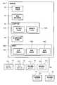
- FIG. 3 is a block diagram of the control device 60.
- the configuration of the control device 60 will be described with reference to FIG. First, the control device 60 has an arousal level determination unit 61 that determines the arousal level of the user OB.
- the arousal level of the user OB is, for example, a scale for distinguishing or classifying whether or not the user OB is in an awakened physiological state. For example, the higher the alertness, the more tense (excited) the user OB is, and the lower the alertness, the sleepier the user OB.
- the arousal level determination unit 61 determines the arousal level of the user OB based on the physiological state of the user by the user state detection unit 50.
- control device 60 has a music selection acquisition unit 62 that selectively acquires music from the sound source SC based on the alertness of the user OB.
- the sound source SC includes a plurality of songs.
- the music selection acquisition unit 62 acquires a music according to the alertness of the user OB from a plurality of music included in the sound source SC.
- the control device 60 has a music reproduction unit 63 that reproduces the music acquired by the music selection acquisition unit 62.
- the music reproduction unit 63 has an audio signal generation unit 63A that generates an electric signal (hereinafter, referred to as an audio signal) for generating a sound from the sound generator 30 in response to the music.
- the audio signal generation unit 63A when the sound generator 30 generates sound in the entire range of a musical piece, the audio signal generation unit 63A generates an acoustic signal AS as an audio signal. Further, when the sound generator 30 generates the sound of only the midrange and the high range of the music, the component of the acoustic signal AS having a predetermined frequency or higher is extracted to generate the audio signal.
- the music reproduction unit 63 has a vibration signal generation unit 63B that generates an electric signal (hereinafter, referred to as a vibration signal) for vibrating the vibration device 40 in response to the music.
- the vibration signal generation unit 63B extracts a low frequency component of the acoustic signal AS to generate a vibration signal. That is, in this embodiment, the vibration signal generation unit 63B generates a vibration signal such that, for example, the vibration device 40 vibrates to express the low-pitched sound of the music.
- the vibration signal generation unit 63B extracts a frequency component (range) in the range of 20 to 200 Hz from the acoustic signal AS to generate a vibration signal. This is because vibrations having a frequency lower than 20 Hz may become unpleasant vibrations that reverberate in the internal organs. Further, a vibration having a frequency higher than 200 Hz may be an unpleasant vibration that feels awkward.
- the configuration of the vibration signal generated by the vibration signal generation unit 63B is not limited to this.
- the control device 60 has a load-related information acquisition unit (hereinafter, simply referred to as an information acquisition unit) 64 that acquires information including a value related to the load applied to the seat 20.
- the information acquisition unit 64 acquires in advance information including a value related to a load applied to the seat 20 in a state where the user OB is not sitting on the seat 20, for example. Then, for example, when the load applied to the seat 20 changes, such as when the user OB sits on the seat 20, or when the load applied to the portion between the vibrating device 40 and the user OB in the seat 20 changes in this embodiment. Obtain information indicating that the load has changed and the load value.
- the information including the value related to the load related to the seat 20 is the information including the value related to the vibration state of the vibrating device 40.
- the information acquisition unit 64 acquires information including a value related to the actual vibration intensity of the vibration device 40.
- the value related to the vibration intensity of the vibrating device 40 is, for example, a value that can be calculated from the actual displacement, speed, acceleration, and the like of the vibrating device 40.
- the vibration device 40 has a displacement sensor, a speed sensor, or an acceleration sensor.
- the information acquisition unit 64 acquires the detected values of these sensors from the vibration device 40 to acquire the actual vibration intensity when the vibration device 40 is vibrating, the difference from the reference strength described later, and the like. To do.
- Information on the load applied to the sheet 20 can be calculated other than the vibration intensity of the vibration device 40. Therefore, if another calculable value is acquired, it can be processed as a value related to the load applied to the sheet 20.
- the control device 60 has a drive unit 65 that drives the sound generator 30 and the vibration device 40 based on the information acquired by the information acquisition unit 64.
- the drive unit 65 includes a voice drive unit 65A that generates electric signals (hereinafter, referred to as voice drive signals) S1 and S2 that drive the sound generator 30, and an electric signal (hereinafter, vibration drive signal) that drives the vibration device 65B. It has a vibration drive unit 65B that generates V1 and V2 (referred to as).
- the voice drive unit 65A has a voice drive signal (first voice drive signal) V1 for driving the center speaker 31 and a voice drive signal (second voice drive signal) V2 for driving the side speaker 32. And generate. Further, the vibration drive unit 65B includes a vibration drive signal (first vibration drive signal) V1 for driving the seat vibration unit 41 and a vibration drive signal (second vibration drive signal) V2 for driving the back vibration unit 42. , Is generated. The drive unit 65 supplies these drive signals to the sound generator 30 and the vibration device 40.
- the vibration drive unit 65B corresponds to the vibration signal generated by the vibration signal generation unit 63B of the music reproduction unit 63, so that the vibration device 40 vibrates at a frequency within the range of 20 to 200 Hz.
- the vibration drive signals V1 and V2 are supplied to the vibration device 40.
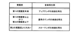
- FIG. 4 is a diagram showing an example of the operation mode of the music playback unit 63.
- the music reproduction unit 63 selects and reproduces music having a different tempo depending on the alertness of the user OB.
- the music playback unit 63 awakens to the user OB. Select and play up-tempo music (generate audio and vibration signals) to encourage.
- the music playback unit 63 prompts the user OB to relax. Select and play a slow tempo song.
- the music reproduction unit 63 selects and plays a music having a normal tempo. You may. If the user OB's alertness is between the first alertness and the second alertness when the music has already been played, the music playback unit 63 plays the played music. May be maintained.
- the music playback unit 63 plays music at a tempo according to the alertness of the user OB. Further, in the present embodiment, the music reproduction unit 63 reproduces music having a slower tempo as the awakening degree of the user OB is higher. Thereby, it is possible to provide music that stabilizes the alertness of the user OB, that is, the physiological state.
- the operation mode of the music playback unit 63 is not limited to this.
- the music reproduction unit 63 may adjust the tempo at the time of reproduction even for the same music.
- the tempo can be adjusted by speeding up the tempo of the music being played instead of playing the up-tempo music. Good.
- the first and second arousal levels which are the criteria for tempo selection by the music playback unit 63, can be variously adjusted.
- the first and second arousal levels may have the same value.
- the music reproduction unit 63 may select and adjust the tempo of the music based on whether or not it exceeds a predetermined arousal level as one threshold value.
- the music playback unit 63 plays music at a fast tempo when the user OB has a low alertness, and plays music at a slow tempo to the user OB when the user OB has a high alertness. It suffices if it is configured as follows.
- FIG. 5 is a diagram showing an example of the operation mode of the vibration drive unit 65B in the drive unit 65.
- the vibration drive unit 65B adjusts the vibration intensity of the vibration device 40 based on the magnitude of the load applied to the seat 20.
- the vibration drive unit 65B vibrates with a strength stronger than the reference strength when the value related to the load applied to the seat (hereinafter referred to as the seat load) is less than the first load (first reference value).
- the device 40 is vibrated.
- the vibration drive unit 65B vibrates the vibrating device 40 with a strength weaker than the reference strength.
- the vibration drive unit 65B vibrates the vibration device 40 with the reference strength.
- the reference strength is, for example, a value related to the load applied to the seat 20 when a user OB under the reference condition (for example, a user OB having a weight of 50 kg) sits on the seat 20 as the reference value of the load. It refers to the actual vibration intensity of the vibrating device 40 when the vibrating device 40 is vibrated by the drive signals V1 and V2 having predetermined characteristics (for example, gain) in order to vibrate the seat 20 to which the load corresponding to the value is applied.
- the seat load when the seat load is less than the first load, it corresponds to the case where the seat 20 is not so loaded, for example, when the weight of the user OB is relatively small (light).
- the vibration device 40 since the force for pressing the vibrating device 40 via the cushion portion 21 is small, when the vibrating drive signals V1 and V2 are supplied to the vibrating device 40 with a gain such that the vibrating device 40 vibrates at the reference strength, the vibration device 40 is actually said to be the same.
- the vibrating device 40 vibrates with a strength stronger than the reference strength.
- the vibration drive unit 65B adjusts the gains of the vibration drive signals V1 and V2 so that stronger vibration is generated.
- the seat load is larger than the second load, it corresponds to the case where the seat 20 is heavily loaded, for example, when the weight of the user OB is relatively large (heavy).
- the vibration drive signals V1 and V2 are supplied to the vibrating device 40 with a gain such that the vibrating device 40 vibrates at the reference strength, the vibrating device 40 actually vibrates at a strength weaker than the reference strength.
- the vibration drive unit 65B adjusts the gains of the vibration drive signals V1 and V2 so that weaker vibration is generated.
- FIGS. 6 and 7 are diagrams showing an example of the operation flow of the control device 60.
- the operation routine of the control device 60 will be described with reference to FIGS. 6 and 7.
- the control device 60 acquires the physiological information of the user OB by the alertness determination unit 61 (step S11).
- the arousal level determination unit 61 determines the arousal level of the user OB based on the physiological information (step S12).
- the music playback unit 63 determines whether or not the arousal level of the user OB is less than the first arousal level (step S13). When the arousal level of the user OB is less than the first arousal level, the music reproduction unit 63 generates an audio signal and a vibration signal from the acoustic signal AS in order to reproduce the up-tempo music (step S14).
- the music playback unit 63 determines whether or not the arousal level is higher than the second arousal level (step S15).
- the music reproduction unit 63 generates an audio signal and a vibration signal from the acoustic signal AS in order to reproduce the slow tempo music (step S16).
- the music reproduction unit 63 reproduces a music having a normal tempo (step S17).
- the information acquisition unit 64 acquires information on the actual vibration intensity of the vibration device 40 as load information (information on the seat load). (Step S21). Further, for example, the information acquisition unit 64 acquires information on the difference between the reference intensity and the actual vibration intensity.
- the vibration drive unit 65B determines whether or not the seat load is less than the first load (step S22).
- the vibration drive unit 65B drives the vibration device 40 so that the vibration device 40 vibrates with a strength stronger than the reference strength (step S23).
- the vibration drive unit 65B adjusts the vibration drive signals V1 and V2 so that the gains of the vibration drive signals V1 and V2 are larger than the gain corresponding to the reference intensity.
- the vibration drive unit 65B determines whether or not the seat load is larger than the second load (step S24).
- the vibration drive unit 65B drives the vibration device 40 so that the vibration device 40 vibrates with a strength weaker than the reference strength (step S25).
- the vibration drive unit 65B adjusts the vibration drive signals V1 and V2 so that the gains of the vibration drive signals V1 and V2 are larger than the gain corresponding to the reference intensity.
- the vibration drive unit 65B drives the vibration device 40 so that the vibration device 40 vibrates at the reference strength (step S26).
- the control device 60 controls the operation of each device and performs a music playback operation.
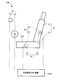
- FIG. 8 is a diagram in which the seat 20, the vibration device 40, and the user OB are modeled to define the transmission characteristics of vibration. Note that FIG. 8 shows a part of the seat portion 21 of the seat 20, the seat portion vibration unit 41 of the vibrating device 40, and the user's first portion BP1. Further, FIG. 8 is a schematic cross-sectional view of these.
- the transmission characteristics until the vibration generated by the vibration device 40 is transmitted to the user OB can be modeled and considered as a viscoelastic model as shown in FIG. 8, for example.
- the seat portion 21 of the seat 20 is composed of a rigid body plate 21A and a cushion portion (a portion easily deformed by applying a load) 21B.
- the seat vibration unit 41 of the vibrating device 40 includes a vibrator (for example, a magnetic material) 41A and a case 41B that supports the vibrator 41A and applies a vibration force (for example, a magnetic force) to the vibrator 41A. , It is embedded in the cushion portion 21B as a whole.
- the mass of the vibrator 41A of the seat vibration unit 41 is mass m1
- the vibrator 41A is supported by the case 41B by the spring constant k1 and the damping coefficient c1.
- the mass of the case 41B is mass m2
- the case portion 41B is arranged between the rigid body plate 21A and the surface 21S
- the cushion portion 21B is supported by the spring constant k2 and the damping coefficient c2.
- the weight of the user OB is set to mass m3.
- the oscillator 41A reciprocates in the case 41B in the direction toward the user OB with a displacement x1, a velocity v1 and an acceleration a1. Further, it is assumed that the force f1 is generated by this reciprocating motion.
- the vibration of the vibrator 41A is transmitted to the case 41B, and reciprocates with a displacement x2, a velocity v2, and an acceleration a2 in the direction toward the user OB. Further, it is assumed that the force f2 is generated by this reciprocating motion.
- the reciprocating motion of the case 41B becomes vibration of the vibrating device 40 and is transmitted in the cushion portion 21B to vibrate the entire cushion portion 21B. Then, the vibration of the cushion portion 21B becomes the vibration (reciprocating motion) of the surface 21S of the seat portion 21.
- the surface 21S of the seat portion 21 reciprocates with a displacement x3, a velocity v3, and an acceleration a3. Further, it is assumed that the force f3 is generated by this reciprocating motion.
- the intensity of vibration perceived by the user OB corresponds to, for example, the magnitude of the force f3 generated by the reciprocating motion of the surface 21S on the sheet 20.
- FIG. 9 shows the simulation results of the relationship between the weight of the user OB, that is, the mass m3 and the acceleration a1 of the vibrator 41A, and the relationship between the mass m3 and the exciting force (force corresponding to the force f3) of the seat 20. It is a figure which shows.
- the masses m1 and m2 were set to 0.05 kg
- the spring constant k1 was set to 1000 N / m
- the damping coefficient c1 was set to 10 N / (m / s).
- the mass m3 that is, the weight of the user OB
- the spring constant k2 of the cushion portion 21B changes within the range of 2000 to 6000 N / m
- the damping coefficient c2 changes from 4 to 12 N. It is assumed that it changes within the range of / (m / s).
- this exemplary numerical value was defined with reference to the material of the seat of a general vehicle or a movie theater.
- the vibration drive unit 65B does not adjust the vibration intensity (in the case of "no control"), the heavier the weight of the user OB, the more the actual acceleration a1 of the vibrator 41A. It can be seen that (that is, the actual vibration intensity of the vibration device 40) becomes smaller.
- the inventors of the present application generate vibration in the seat 20 and transmit (perceive) it to the user OB, and when the load applied to the seat 20 is large such as the weight of the user OB is heavy, It has been found that the user OB can sufficiently perceive the vibration even if the vibrating device 40 does not vibrate strongly. Similarly, when the load applied to the seat 20 is small, such as when the weight of the user OB is light, the inventors of the present application cannot sufficiently make the user OB perceive the vibration unless the vibrating device 40 vibrates strongly. I found.
- the vibration drive unit 65B acquires information on the seat load based on the actual vibration strength of the vibration device 40 (that is, the difference from the reference strength). Then, as shown in "Controlled" in the upper graph of FIG. 9, the vibration drive unit 65B causes a weak vibration when the seat load is large and a strong vibration when the seat load is small. To drive.
- the vibration system 10 has a sound generator 30 and a vibration device 40, and music is reproduced by these has been described. Further, a case where the vibrating device 40 vibrates in response to music has been described.
- the configuration of the vibration system 10 is not limited to this.
- the vibration system 10 does not have to have the sound generator 30.
- the control device 60 functions as a control device for the vibration device 40.
- the vibration device 40 includes a seat vibration unit 41 and a back vibration unit 42 .
- the vibrating device 40 may have another vibrating unit or may consist of only one vibrating unit.
- the vibration device 40 may be configured to give vibration to the user OB via a member other than the seat 20.
- the vibration device 40 may be configured to transmit vibration to the user OB via various support members that support the user OB.
- control device 60 adjusts the tempo of the music to be played according to the alertness of the user OB has been described.
- the control device 60 is not limited to the case where the tempo is adjusted.
- the vibration system 10 is not limited to the case where the user state detection unit 50 is provided.
- control device 60 is a vibration device other than the vibration device 40, the same operation can be performed as long as it is a device that transmits vibration to the user OB via various support members such as the seat 20.
- the vibration drive unit 65B adjusts the vibration intensity of the vibration device 40 depending on whether the seat load is less than the first load or larger than the second load. The case was explained. However, for example, the vibration drive unit 65B sets the load between the first and second loads as a reference load (reference value), and adjusts the vibration intensity depending on whether or not the seat load is within the range of the reference load. You may.
- the control device 60 transmits drive signals (vibration drive signals V1 and V2) to the vibration device 40 that transmits vibration to the user OB via the support member (seat 20) that supports the user OB. It has a vibration drive unit 65B to be supplied, and an information acquisition unit 64 to acquire information including a value related to a load applied to the support member.
- the vibration drive unit 65B supplies a signal indicating the reference vibration intensity (reference intensity) as a drive signal to the vibration device 40, and supplies the support member with a signal indicating the reference vibration intensity (reference intensity).
- a signal indicating a vibration strength weaker than the reference vibration strength is supplied to the vibrating device 40 as a drive signal, and the value related to the load applied to the support member is smaller than the reference value. Is supplied to the vibration device 40 as a drive signal indicating a vibration intensity stronger than the reference vibration intensity. Therefore, it is possible to provide a control device 60 capable of vibrating the vibrating device 40 in a preferred manner according to the user.
- the control device 60 supplies drive signals (vibration drive signals V1 and V2) to the vibration device 40 that transmits vibration to the user via a support member (seat 20) that supports the user OB.
- the vibration drive unit 65B includes an information acquisition unit 64 that acquires information including a value related to the load applied to the support member, and the vibration drive unit 65B has a vibration intensity that decreases as the value related to the load applied to the support member increases. Is supplied to the vibrating device 40. Therefore, it is possible to provide a control device 60 capable of vibrating the vibrating device 40 in a preferred manner according to the user.
- this embodiment can also be implemented as a method of controlling the vibration device 40 by executing, for example, the step shown in FIG. 7. More specifically, for example, the control method of the vibrating device 40 according to the present embodiment includes step S21 for acquiring information including a value related to the load applied to the support member (seat 20) that supports the user OB, and step S21.
- Drive signals vibration drive signals V1 and V2 indicating the reference vibration intensity (reference intensity) when the value related to the load applied to the support member is within the range of the reference value with respect to the vibration device 40 that transmits the vibration to the user OB via the user OB.
- a drive signal indicating a vibration strength weaker than the standard vibration strength is supplied, and the value related to the load applied to the support member is higher than the reference value.
- it includes a step of supplying a drive signal indicating a vibration intensity stronger than the reference vibration intensity (steps S26, S23, S25, respectively). Therefore, it is possible to provide a control method of the vibrating device capable of vibrating the vibrating device 40 in a preferable manner according to the user.
- this embodiment can also be implemented as, for example, a program for operating a computer for controlling a vibration device like a control device 60, or a program for executing the above-mentioned control method. More specifically, in the program according to the present embodiment, the computer obtains information including a value related to the load applied to the support member (seat 20) that supports the user OB, and the user OB via the support member. When the value related to the load applied to the support member is within the range of the reference value, the drive signal (vibration drive signal V1 and V2) indicating the reference vibration strength (reference strength) is supplied to the vibration device 40 that transmits the vibration to.
- a drive signal indicating a vibration strength weaker than the standard vibration strength is supplied, and when the value related to the load applied to the support member is smaller than the reference value, the drive signal is supplied.
- the steps (steps S26, S23, S25, respectively) of supplying a drive signal showing a vibration intensity stronger than the reference vibration intensity are executed. Therefore, it is possible to provide a control program of the vibrating device capable of vibrating the vibrating device 40 in a preferable manner according to the user. Further, for example, by recording the program, the present embodiment can also be implemented as a recording medium.
- FIG. 10 is a diagram showing a part of the configuration of the vibration system 10A according to the second embodiment.
- the vibration system 10A has the same configuration as the vibration system 10 except that it has a pressure gauge 70 as a means for detecting the seat load.
- the value related to the seat load is not detected as the actual vibration intensity of the vibration device 40, but is detected as the pressure applied to the seat.
- the information acquisition unit 64 of the control device 60 acquires information on the pressure applied to the seat as load information. That is, in this embodiment, the value related to the load applied to the sheet 20 is the value related to the pressure applied to the sheet 20.
- FIG. 11 is a diagram showing a part of the operation flow of the control device 60.
- the control device 60 executes the following steps instead of step S21.
- the information acquisition unit 64 acquires information on the measured value of the pressure gauge 70 as load information (step S21A).
- the operation flow before and after this step S21A is the same as in FIGS. 6 and 7.
- the information regarding the load applied to the sheet 20 acquired by the information acquisition unit 64 may be the information regarding the pressure applied to the sheet 20. In this case, it is determined that the greater the pressure applied to the sheet 20, the greater the load applied to the sheet 20.
- the vibration drive unit 65B vibrates with a strong (or weak) intensity with respect to the vibration device 40.
- FIG. 12 is a diagram showing a part of the configuration of the vibration system 10B according to the third embodiment.
- the vibration system 10B includes an expansion device 80 that changes the position of the vibration device 40 in the seat 20 by expanding and contracting. Further, the vibration system 10B has a control device 60A for controlling the expansion device 80 in addition to the sound generator 30 and the vibration device 40.
- the vibration system 10B has the same configuration as the vibration system 10 in other respects.
- the expansion device 80 expands and contracts, respectively, to change the position of the seat vibration unit 41 between the seat portion 21 and the surface 21S, and the seat expansion unit 81 and the back vibration unit. It has a back expansion unit 82 that changes the position of the back 22 with the surface 22S of 42.
- each of the seat expansion unit 81 and the back expansion unit 82 includes a bladder.
- FIG. 13 is a block diagram of the control device 60A.
- the control device 60A has the same configuration as the control device 60 except for the configuration of the drive unit 65M.
- the drive unit 65M is an electric signal for expanding and contracting the expansion device 80 in addition to the voice drive unit 65A and the vibration drive unit 65B (hereinafter, referred to as first and second expansion drive signals). It has an expansion drive unit 65C that supplies E1 and E2 to the expansion device 80 to drive the expansion device 80.
- FIG. 14 is a diagram showing an example of the operation flow of the control device 60A.
- FIG. 14 shows a part of the operation flow of the control device 60A.
- the control device 60A executes the following steps in place of steps S23, S25 and S25.
- step S22 when it is determined in step S22 that the seat load is less than the first load, the expansion drive unit 65C expands the expansion device 80 to bring the vibration device 40 closer to the user OB (step S23A). ..
- the vibration of the vibrating device 40 is transmitted to the user OB more strongly.
- step S24 when it is determined in step S24 that the seat load is larger than the second load, the expansion drive unit 65C contracts the expansion device 80 and separates the user OB from the vibration device 40 (step S25A).
- the situation is the same as when the sheet 20 is not further crushed, and the vibration of the vibrating device is weaker and is transmitted to the user OB.
- step S24 When it is determined in step S24 that the seat load is equal to or less than the second load, the expansion drive unit 65C maintains the state of the expansion device 80 so that the relative position between the vibration device 40 and the user OB is reached. To maintain.
- the vibration system 10B has an expansion device 80 that adjusts the position of the vibration device 40 with the user OB (surfaces 21S and 22S of the sheet 20). Further, the control device 60A adjusts the positions of the vibration device 40 and the user OB by driving the expansion device 80, and adjusts the intensity of the vibration transmitted by the vibration device 40 to the user OB.
- the vibration drive unit 65B does not need to change the vibration intensity by adjusting the vibration drive signals V1 and V2.
- the vibration system 10B may have an actuator that changes the position of the vibration device 40 with the user OB.
- the control device 60A includes the vibration drive unit 65B for driving the vibration device 40 that transmits vibration to the user OB via the support member (seat 20) that supports the user OB, and the vibration device 40.
- the actuator drive unit (expansion drive unit 65C) that drives the actuator (expansion device 80) that changes the relative position between the support member and the portion (surface 21S or 22S) that transmits vibration to the user OB, and the support member. It has an information acquisition unit 64 that acquires information including a value related to a load.
- the actuator drive unit brings the vibrating device 40 closer to the portion of the support member that transmits vibration to the user OB, and the value related to the load applied to the support member is the reference value. If it is larger than the value, the vibrating device 40 is moved away from the portion of the support member that transmits vibration to the user OB. Therefore, for example, it is possible to provide a control device 60A capable of vibrating the vibrating device 40 in a preferred manner according to the user.
Landscapes
- Health & Medical Sciences (AREA)
- Life Sciences & Earth Sciences (AREA)
- Veterinary Medicine (AREA)
- Public Health (AREA)
- General Health & Medical Sciences (AREA)
- Animal Behavior & Ethology (AREA)
- Anesthesiology (AREA)
- Acoustics & Sound (AREA)
- Hematology (AREA)
- Biomedical Technology (AREA)
- Physics & Mathematics (AREA)
- Engineering & Computer Science (AREA)
- Psychology (AREA)
- Heart & Thoracic Surgery (AREA)
- Epidemiology (AREA)
- Pain & Pain Management (AREA)
- Physical Education & Sports Medicine (AREA)
- Rehabilitation Therapy (AREA)
- Percussion Or Vibration Massage (AREA)
- Chair Legs, Seat Parts, And Backrests (AREA)
- Seats For Vehicles (AREA)
- Auxiliary Drives, Propulsion Controls, And Safety Devices (AREA)
Priority Applications (4)
| Application Number | Priority Date | Filing Date | Title |
|---|---|---|---|
| JP2021513585A JPWO2020209140A1 (https=) | 2019-04-11 | 2020-03-31 | |
| JP2023029323A JP2023059996A (ja) | 2019-04-11 | 2023-02-28 | 振動装置の制御装置、振動装置の制御方法、プログラム及び記録媒体 |
| JP2024025571A JP2024061691A (ja) | 2019-04-11 | 2024-02-22 | 振動装置の制御装置、振動装置の制御方法、プログラム及び記録媒体 |
| JP2025014722A JP2025061996A (ja) | 2019-04-11 | 2025-01-31 | 振動装置の制御装置、振動装置の制御方法、プログラム及び記録媒体 |
Applications Claiming Priority (2)
| Application Number | Priority Date | Filing Date | Title |
|---|---|---|---|
| JP2019075717 | 2019-04-11 | ||
| JP2019-075717 | 2019-04-11 |
Publications (1)
| Publication Number | Publication Date |
|---|---|
| WO2020209140A1 true WO2020209140A1 (ja) | 2020-10-15 |
Family
ID=72751585
Family Applications (1)
| Application Number | Title | Priority Date | Filing Date |
|---|---|---|---|
| PCT/JP2020/014792 Ceased WO2020209140A1 (ja) | 2019-04-11 | 2020-03-31 | 振動装置の制御装置、振動装置の制御方法、プログラム及び記録媒体 |
Country Status (2)
| Country | Link |
|---|---|
| JP (4) | JPWO2020209140A1 (https=) |
| WO (1) | WO2020209140A1 (https=) |
Cited By (3)
| Publication number | Priority date | Publication date | Assignee | Title |
|---|---|---|---|---|
| US20230166292A1 (en) * | 2020-04-30 | 2023-06-01 | Pioneer Corporation | Vibration signal generation device |
| JP2023537551A (ja) * | 2021-07-15 | 2023-09-04 | ハルシオン インコーポレイテッド | マットレス及びその制御方法 |
| JP2025065206A (ja) * | 2021-04-28 | 2025-04-17 | ヤマハ株式会社 | 信号生成装置、情報生成装置、信号生成方法および情報生成方法 |
Citations (6)
| Publication number | Priority date | Publication date | Assignee | Title |
|---|---|---|---|---|
| JPH09266935A (ja) * | 1996-04-01 | 1997-10-14 | Toyota Motor Corp | 加振シートの振動制御装置 |
| JP2001086580A (ja) * | 1999-09-14 | 2001-03-30 | Akuubu Lab:Kk | 振動音楽の表現方法及びその装置 |
| JP2007137387A (ja) * | 2005-11-22 | 2007-06-07 | Toyota Motor Corp | 車両用シート |
| JP2011048023A (ja) * | 2009-08-25 | 2011-03-10 | Pioneer Electronic Corp | 体感振動生成装置および体感振動生成方法 |
| JP2018025869A (ja) * | 2016-08-08 | 2018-02-15 | 株式会社デンソー | 運転支援装置 |
| JP2018052385A (ja) * | 2016-09-30 | 2018-04-05 | パイオニア株式会社 | 振動制御装置 |
Family Cites Families (2)
| Publication number | Priority date | Publication date | Assignee | Title |
|---|---|---|---|---|
| JP3037838U (ja) * | 1996-08-06 | 1997-05-27 | ツ−ケン・チェン | サウンドコントロールマッサージ装置 |
| US7619505B2 (en) * | 2006-10-31 | 2009-11-17 | Hyundai Motor Company | Vehicle direction guide vibration system and method |
-
2020
- 2020-03-31 JP JP2021513585A patent/JPWO2020209140A1/ja active Pending
- 2020-03-31 WO PCT/JP2020/014792 patent/WO2020209140A1/ja not_active Ceased
-
2023
- 2023-02-28 JP JP2023029323A patent/JP2023059996A/ja active Pending
-
2024
- 2024-02-22 JP JP2024025571A patent/JP2024061691A/ja active Pending
-
2025
- 2025-01-31 JP JP2025014722A patent/JP2025061996A/ja active Pending
Patent Citations (6)
| Publication number | Priority date | Publication date | Assignee | Title |
|---|---|---|---|---|
| JPH09266935A (ja) * | 1996-04-01 | 1997-10-14 | Toyota Motor Corp | 加振シートの振動制御装置 |
| JP2001086580A (ja) * | 1999-09-14 | 2001-03-30 | Akuubu Lab:Kk | 振動音楽の表現方法及びその装置 |
| JP2007137387A (ja) * | 2005-11-22 | 2007-06-07 | Toyota Motor Corp | 車両用シート |
| JP2011048023A (ja) * | 2009-08-25 | 2011-03-10 | Pioneer Electronic Corp | 体感振動生成装置および体感振動生成方法 |
| JP2018025869A (ja) * | 2016-08-08 | 2018-02-15 | 株式会社デンソー | 運転支援装置 |
| JP2018052385A (ja) * | 2016-09-30 | 2018-04-05 | パイオニア株式会社 | 振動制御装置 |
Cited By (5)
| Publication number | Priority date | Publication date | Assignee | Title |
|---|---|---|---|---|
| US20230166292A1 (en) * | 2020-04-30 | 2023-06-01 | Pioneer Corporation | Vibration signal generation device |
| US12070771B2 (en) * | 2020-04-30 | 2024-08-27 | Pioneer Corporation | Vibration signal generation device |
| JP2025065206A (ja) * | 2021-04-28 | 2025-04-17 | ヤマハ株式会社 | 信号生成装置、情報生成装置、信号生成方法および情報生成方法 |
| JP2023537551A (ja) * | 2021-07-15 | 2023-09-04 | ハルシオン インコーポレイテッド | マットレス及びその制御方法 |
| JP7558583B2 (ja) | 2021-07-15 | 2024-10-01 | ハルシオン インコーポレイテッド | マットレス及びその制御方法 |
Also Published As
| Publication number | Publication date |
|---|---|
| JPWO2020209140A1 (https=) | 2020-10-15 |
| JP2023059996A (ja) | 2023-04-27 |
| JP2025061996A (ja) | 2025-04-11 |
| JP2024061691A (ja) | 2024-05-07 |
Similar Documents
| Publication | Publication Date | Title |
|---|---|---|
| JP2023059996A (ja) | 振動装置の制御装置、振動装置の制御方法、プログラム及び記録媒体 | |
| US20260004645A1 (en) | Tactile transducer with digital signal processing for improved fidelity | |
| EP3054702B1 (en) | Speakers and headphones related to vibrations in an audio system, and methods for operating same | |
| JP2020065287A (ja) | 音響の包括的な知覚のための装置 | |
| CN109314806A (zh) | 通过调节振动增强声音感知 | |
| CN101193454A (zh) | 体感音响系统 | |
| JP2026021538A (ja) | 振動装置、振動装置の駆動方法、プログラム及び記録媒体 | |
| KR102691016B1 (ko) | 스피커를 이용한 차량용 진동 시트 및 그 제어 방법 | |
| JP2554224B2 (ja) | リラクゼイションシステム | |
| JPWO2019211990A1 (ja) | 振動制御装置 | |
| KR101991671B1 (ko) | 차량용 가상 엔진 사운드 발생장치 | |
| CN119160115A (zh) | 用于控制交通工具的舒适功能的方法和交通工具装置 | |
| JP2002354567A (ja) | 音響装置、音響装置を内蔵した家具及び音響装置を座席に内蔵した交通機関 | |
| JP2008289756A (ja) | 睡眠誘導装置 | |
| CN121127406A (zh) | 车辆触觉系统 | |
| CN110691713B (zh) | 振动产生装置和振动产生方法 | |
| KR20230094849A (ko) | 차량 시트 제어 장치 및 방법 | |
| CN117351992A (zh) | 情感关怀设备及其方法 | |
| US20250331647A1 (en) | Tunable haptic chair | |
| JP7846747B2 (ja) | 振動装置 | |
| CN121175017A (zh) | 车辆触觉系统 | |
| JP2024106491A (ja) | シート用振動伝達装置、及び振動伝達シート | |
| JP2024094469A (ja) | シート用振動伝達装置 | |
| JP2024043115A (ja) | シート用振動伝達装置、シート用振動制御装置、振動伝達シート、及び振動伝達装置の制御方法 | |
| JP2024074454A (ja) | シート用振動伝達装置、及び振動伝達シート |
Legal Events
| Date | Code | Title | Description |
|---|---|---|---|
| 121 | Ep: the epo has been informed by wipo that ep was designated in this application |
Ref document number: 20787973 Country of ref document: EP Kind code of ref document: A1 |
|
| ENP | Entry into the national phase |
Ref document number: 2021513585 Country of ref document: JP Kind code of ref document: A |
|
| NENP | Non-entry into the national phase |
Ref country code: DE |
|
| 122 | Ep: pct application non-entry in european phase |
Ref document number: 20787973 Country of ref document: EP Kind code of ref document: A1 |