WO2020208753A1 - 押出成形機、及び成形体の製造方法 - Google Patents
押出成形機、及び成形体の製造方法 Download PDFInfo
- Publication number
- WO2020208753A1 WO2020208753A1 PCT/JP2019/015687 JP2019015687W WO2020208753A1 WO 2020208753 A1 WO2020208753 A1 WO 2020208753A1 JP 2019015687 W JP2019015687 W JP 2019015687W WO 2020208753 A1 WO2020208753 A1 WO 2020208753A1
- Authority
- WO
- WIPO (PCT)
- Prior art keywords
- extrusion
- molding machine
- heat insulating
- extrusion molding
- temperature
- Prior art date
- Legal status (The legal status is an assumption and is not a legal conclusion. Google has not performed a legal analysis and makes no representation as to the accuracy of the status listed.)
- Ceased
Links
Images


Classifications
-
- B—PERFORMING OPERATIONS; TRANSPORTING
- B28—WORKING CEMENT, CLAY, OR STONE
- B28B—SHAPING CLAY OR OTHER CERAMIC COMPOSITIONS; SHAPING SLAG; SHAPING MIXTURES CONTAINING CEMENTITIOUS MATERIAL, e.g. PLASTER
- B28B3/00—Producing shaped articles from the material by using presses; Presses specially adapted therefor
- B28B3/20—Producing shaped articles from the material by using presses; Presses specially adapted therefor wherein the material is extruded
- B28B3/201—Means for heating or cooling the barrel
-
- B—PERFORMING OPERATIONS; TRANSPORTING
- B28—WORKING CEMENT, CLAY, OR STONE
- B28B—SHAPING CLAY OR OTHER CERAMIC COMPOSITIONS; SHAPING SLAG; SHAPING MIXTURES CONTAINING CEMENTITIOUS MATERIAL, e.g. PLASTER
- B28B3/00—Producing shaped articles from the material by using presses; Presses specially adapted therefor
- B28B3/20—Producing shaped articles from the material by using presses; Presses specially adapted therefor wherein the material is extruded
- B28B3/26—Extrusion dies
- B28B3/269—For multi-channeled structures, e.g. honeycomb structures
-
- B—PERFORMING OPERATIONS; TRANSPORTING
- B28—WORKING CEMENT, CLAY, OR STONE
- B28B—SHAPING CLAY OR OTHER CERAMIC COMPOSITIONS; SHAPING SLAG; SHAPING MIXTURES CONTAINING CEMENTITIOUS MATERIAL, e.g. PLASTER
- B28B3/00—Producing shaped articles from the material by using presses; Presses specially adapted therefor
- B28B3/20—Producing shaped articles from the material by using presses; Presses specially adapted therefor wherein the material is extruded
- B28B3/206—Forcing the material through screens or slots
-
- B—PERFORMING OPERATIONS; TRANSPORTING
- B28—WORKING CEMENT, CLAY, OR STONE
- B28B—SHAPING CLAY OR OTHER CERAMIC COMPOSITIONS; SHAPING SLAG; SHAPING MIXTURES CONTAINING CEMENTITIOUS MATERIAL, e.g. PLASTER
- B28B3/00—Producing shaped articles from the material by using presses; Presses specially adapted therefor
- B28B3/20—Producing shaped articles from the material by using presses; Presses specially adapted therefor wherein the material is extruded
- B28B3/22—Producing shaped articles from the material by using presses; Presses specially adapted therefor wherein the material is extruded by screw or worm
-
- B—PERFORMING OPERATIONS; TRANSPORTING
- B28—WORKING CEMENT, CLAY, OR STONE
- B28B—SHAPING CLAY OR OTHER CERAMIC COMPOSITIONS; SHAPING SLAG; SHAPING MIXTURES CONTAINING CEMENTITIOUS MATERIAL, e.g. PLASTER
- B28B3/00—Producing shaped articles from the material by using presses; Presses specially adapted therefor
- B28B3/20—Producing shaped articles from the material by using presses; Presses specially adapted therefor wherein the material is extruded
- B28B3/26—Extrusion dies
- B28B3/2654—Means for heating or cooling the die
-
- B—PERFORMING OPERATIONS; TRANSPORTING
- B29—WORKING OF PLASTICS; WORKING OF SUBSTANCES IN A PLASTIC STATE IN GENERAL
- B29C—SHAPING OR JOINING OF PLASTICS; SHAPING OF MATERIAL IN A PLASTIC STATE, NOT OTHERWISE PROVIDED FOR; AFTER-TREATMENT OF THE SHAPED PRODUCTS, e.g. REPAIRING
- B29C48/00—Extrusion moulding, i.e. expressing the moulding material through a die or nozzle which imparts the desired form; Apparatus therefor
- B29C48/25—Component parts, details or accessories; Auxiliary operations
-
- B—PERFORMING OPERATIONS; TRANSPORTING
- B28—WORKING CEMENT, CLAY, OR STONE
- B28B—SHAPING CLAY OR OTHER CERAMIC COMPOSITIONS; SHAPING SLAG; SHAPING MIXTURES CONTAINING CEMENTITIOUS MATERIAL, e.g. PLASTER
- B28B3/00—Producing shaped articles from the material by using presses; Presses specially adapted therefor
- B28B3/20—Producing shaped articles from the material by using presses; Presses specially adapted therefor wherein the material is extruded
- B28B2003/203—Producing shaped articles from the material by using presses; Presses specially adapted therefor wherein the material is extruded for multi-channelled structures, e.g. honeycomb structures
Definitions
- the present invention relates to an extrusion molding machine and a method for manufacturing a molded product.
- An extrusion molding machine is used to manufacture various molded products.
- a honeycomb-shaped ceramic structure used for a catalytic carrier for purifying automobile exhaust gas a diesel particulate filter (DPF), a gasoline particulate filter (GPF), a heat storage body for a combustion device, etc.
- DPF diesel particulate filter
- GPF gasoline particulate filter
- the mainstream is to manufacture a honeycomb-shaped ceramic molded body using an extrusion molding machine.
- Patent Document 1 As a technique for improving the dimensional accuracy of a molded product obtained by an extrusion molding machine, for example, in Patent Document 1, a heating element is arranged in a front section adjacent to an extrusion mold to determine the temperature of a ceramic batch material (molding material). A technique has been proposed in which the extrusion speed of an extruded product is controlled to improve the dimensional accuracy of the extruded product. Further, in Patent Document 2, the resistance tube between the rectifying plate and the die (base) of the extrusion molding machine is provided so as to penetrate the tube wall of the resistance tube, and the length protruding inward of the resistance tube is long. A technique for arranging a plurality of freely changeable pins and controlling the temperature of the pins to make the extrusion speed of the raw material composition (molding material) introduced into the die uniform and improve the dimensional accuracy of the molded product. Has been proposed.
- Patent Document 1 Since the technique described in Patent Document 1 requires many devices for temperature control of the molding material, the devices become large and complicated. In addition, when the molding material is heated, the amount of electricity increases, so that the manufacturing cost also increases. In the technique described in Patent Document 2, since the pin impedes the flow of the molding material, the extrusion pressure must be increased in order to secure a specific extrusion speed. Further, since the contact area between the pin and the molding material is small, it takes time to control the temperature by the pin.
- the present invention has been made to solve the above problems, and an object of the present invention is to provide an extrusion molding machine capable of producing a molded product having high dimensional accuracy. Another object of the present invention is to provide a method for producing a molded product having high dimensional accuracy.
- the present inventors have found that the non-uniform temperature distribution of the molding material, which affects the extrusion rate, is caused by the extrusion portion cooling the molding portion. Based on the finding that the heat insulating member is arranged at a predetermined position, it has been found that the temperature distribution of the molding material can be made uniform, and the present invention has been completed.
- the present invention includes an extruded portion having a screw and a barrel capable of accommodating the screw, a molded portion having a base at one end and the other end connected to the extruded port of the extruded portion, and the extruded portion.
- An extrusion molding machine including a rectifying plate arranged between the molding portion and the rectifying plate, wherein a heat insulating member is arranged between the molding portion and the rectifying plate.
- an extrusion molding machine capable of producing a molded product having high dimensional accuracy. Further, according to the present invention, it is possible to provide a method for producing a molded product having high dimensional accuracy.
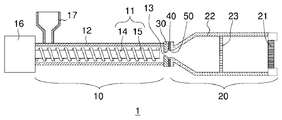
- FIG. 1 is a schematic view showing a schematic configuration of an extrusion molding machine according to a first embodiment of the present invention.
- the extrusion molding machine 1 according to the present embodiment is arranged between the extrusion section 10, the molding section 20 connected to the extrusion section 10, and the extrusion section 10 and the molding section 20.
- a heat insulating member 40 arranged between the straightening vane 30 and the molding portion 20 and the straightening vane 30 is provided.
- the extrusion section 10 has a screw 11 and a barrel 12 capable of accommodating the screw 11.
- the molding portion 20 has a base 21 at one end, and the other end is connected to the extrusion port 13 of the extrusion portion 10.
- the molding material is kneaded in the extrusion section 10. At this time, if the temperature inside the extrusion portion 10 is high, the molding material may dry and harden. Therefore, the extrusion portion 10 is cooled in order to control the temperature inside the extrusion portion 10. On the other hand, since the molding unit 20 is not cooled, the temperature of the molding material discharged from the extrusion port 13 of the extrusion unit 10 gradually rises as it advances to the molding unit 20 through the straightening vane 30.
- the heat insulating member 40 is not arranged between the molding portion 20 and the straightening vane 30, the molded portion 20 on the extrusion portion 10 side is cooled by the influence of the cooled extrusion portion 10. It ends up. In such a state, the temperature of the central portion tends to be high and the temperature of the outer peripheral portion tends to be low in the cross section perpendicular to the extrusion direction (advancing direction) of the molding material. Since the temperature of the molding material affects the extrusion speed, the extrusion speed of the central portion is high and the extrusion speed of the outer peripheral portion is slow, so that a molded product having a desired dimensional accuracy cannot be obtained.
- the heat insulating member 40 is arranged between the molding unit 20 and the straightening vane 30, the space between the extrusion unit 10 and the molding unit 20 is insulated. It is possible to prevent the molded portion 20 on the extrusion portion 10 side from being cooled due to the influence of the cooled extrusion portion 10. Therefore, the difference between the temperature of the central portion and the temperature of the outer peripheral portion becomes small in the cross section perpendicular to the extrusion direction of the molding material. As a result, the extrusion speed in the molded portion 20 is made uniform, and the dimensional accuracy of the molded product can be improved.
- the extrusion portion 10 is not particularly limited as long as it has the screw 11 and the barrel 12 capable of accommodating the screw 11, and those known in the art can be used.
- the screw 11 preferably has a screw shaft 14 and a blade portion 15 formed spirally along the screw shaft 14.
- the screw 11 is preferably a biaxial screw that rotates in the same direction, and more preferably a meshing type biaxial screw, from the viewpoint of kneadability of the molding material, particularly the ceramic molding material.
- the pair of screws 11 are arranged in parallel inside the barrel 12.
- the root portion of the screw 11 is connected to the drive device 16.
- the drive device 16 includes a motor and a gearbox (not shown), and rotates the screw 11 by controlling the rotation speed so as to obtain a predetermined extrusion pressure.
- a material input section 17 for supplying a molding material into the extrusion section 10 is provided on the upstream side of the extrusion section 10. The molding material supplied from the material input section 17 is kneaded by the screw 11 and supplied to the molding section 20.
- the molding section 20 includes a drum 22 having a space inside, has a base 21 at one end, and is connected to the extrusion port 13 of the extrusion section 10 at the other end.
- the shape of the drum 22 is not particularly limited, and a reduced diameter portion or an enlarged diameter portion may be partially provided.
- the drum 22 has a diameter-expanded portion on the extrusion port 13 side.
- the drum 22 having such a structure may be composed of one member, but may be composed of a plurality of members. When the drum 22 is composed of a plurality of members, the drum 22 can be obtained by combining the enlarged diameter drum and the straight drum.
- the shape of the base 21 is not particularly limited, and can be appropriately set according to the shape of the molded product to be manufactured. For example, when producing a molded product having a honeycomb shape, a base 21 having a slit corresponding to the thickness of the partition wall of the honeycomb molded product is used.
- the screen (filtration net) 23 is provided in the drum 22 (molding portion 20).
- the screen 23 is formed of a mesh-like material, can remove coarse particles and other impurities mixed in the molding material, and can stabilize the molding material supplied to the base 21.
- the outer circumference of the drum 22 (molded portion 20) is preferably covered with a heat insulating sheet (not shown).
- a heat insulating sheet not shown.
- the straightening vane 30 is arranged between the extrusion portion 10 and the molding portion 20.
- the straightening vane 30 has a through hole and has a function of adjusting the behavior of the molding material.
- the number, position and shape of the through holes are not particularly limited and can be set as appropriate.
- the material of the straightening vane 30 is not particularly limited, but iron-based or stainless steel-based materials can be used.
- the heat insulating member 40 is arranged between the molding portion 20 and the straightening vane 30.
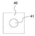
- FIG. 2 shows a front view of the heat insulating member 40 as seen from the straightening vane 30 side.
- the heat insulating member 40 has a through hole 41 in the center through which the molding material can pass.
- the heat insulating member 40 is not particularly limited, but preferably has a thermal conductivity of 0.5 W / m ⁇ K or less. With the heat insulating member 40 having such a thermal conductivity, it is possible to sufficiently secure the heat insulating effect between the extruded portion 10 and the molded portion 20.
- the thermal conductivity of the heat insulating member 40 is preferable because the smaller it is, the higher the heat insulating effect is, but the lower limit thereof is 0.02 W / m ⁇ K in consideration of available materials. Further, in the present specification, the “thermal conductivity” means the thermal conductivity measured at 25 ° C.
- the thickness of the heat insulating member 40 in the extrusion direction is not particularly limited, but is preferably 1 to 50 mm. With the heat insulating member 40 having such a thickness, it is possible to sufficiently secure the heat insulating effect between the extruded portion 10 and the molded portion 20.
- the material of the heat insulating member 40 is not particularly limited as long as it has heat insulating properties, but it is preferably formed of a heat insulating resin.
- the heat insulating resin is not particularly limited, and those known in the art can be used. Examples of the heat insulating resin include synthetic resins such as polyacetal resin, polyamide resin, polyethylene resin, and polypropylene resin.
- the heat insulating member 40 may come into contact with the molding material, but may be worn due to the contact with the molding material. In such a case, it is preferable to arrange the protective member 50 for protecting the heat insulating member 40 at a position between the molding unit 20 and the straightening vane 30 in contact with the molding material.
- the protective member 50 may be an individual component, but as shown in FIG. 1, the protective member 50 may be integrally formed with the drum 22 by processing the end portion of the drum 22 in contact with the heat insulating member 40.
- the material of the protective member 50 is not particularly limited, but the same material as the drum 22 (for example, iron-based material, stainless steel-based material, etc.) can be used.
- the extrusion molding machine 1 having the above structure can be used in a method for manufacturing a molded product.
- the extrusion molding machine 1 is suitable for use in a method for manufacturing a ceramic molded body using a ceramic molding material, particularly a honeycomb ceramic molded body. According to the method for manufacturing a molded product using the extrusion molding machine 1, a molded product with high dimensional accuracy can be obtained.
- the molding material is supplied from the material input portion 17 to the inside of the barrel 12.
- the molding material is kneaded while being subjected to shearing force by the rotation of the screw 11, and is conveyed to the extrusion port 13 side at the tip of the barrel 12.
- the molding material extruded from the extrusion port 13 of the barrel 12 passes through the through hole of the straightening vane 30, passes through the screen 23, and is supplied to the base 21.
- the molding material is extruded through the base 21 to obtain a molded product having a desired shape.
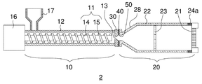
- FIG. 3 is a schematic view showing a schematic configuration of an extrusion molding machine according to a second embodiment of the present invention. As shown in FIG. 3, in the extrusion molding machine 2 according to the present embodiment, the temperature control means 24a is provided between the screen 23 and the base 21.
- the temperature adjusting means 24a By controlling the temperature of the outer peripheral portion of the molding material by the temperature adjusting means 24a, it becomes difficult for the convex portion to be formed on the end face of the molded body, and the dimensional accuracy of the molded body can be further improved. Although it depends on the size of the molded product to be produced (particularly, the diameter of the cross section perpendicular to the extrusion direction) and the characteristics of the molding material used, for example, the outer peripheral portion of the molding material is heated by the temperature controlling means 24a, and the temperature of the outer peripheral portion is heated. The above effect can be obtained by setting the temperature higher than the temperature of the central portion. However, the above effect may be obtained when the difference between the temperature of the outer peripheral portion and the temperature of the central portion is small. Therefore, the temperature adjusting means 24a depends on the size of the molded product to be manufactured and the characteristics of the molding material used. Temperature control should be performed by.
- the temperature controlling means 24a is not particularly limited, and those known in the art can be used. Among them, it is preferable to use a temperature control drum in which a fluid can flow inside as the temperature control means 24a. Since the temperature of the temperature control drum can be controlled by adjusting the temperature of the fluid, it is possible to reduce the consumption of electricity as compared with the case where a heating means such as a heating element is used. For example, the molding material can be easily and efficiently heated by circulating hot water whose temperature is controlled by using a boiler or the like through a temperature control drum.
- FIG. 4 shows a front view of the temperature control drum as viewed from the drum 22 side.
- the temperature control drum 25 has a fluid supply port 26 and a fluid discharge port 27, and a fluid flow path is formed in the circumferential direction.
- the supply port 26 and the discharge port 27 are connected to the fluid supply device via a tube or the like. By circulating the fluid while controlling the temperature of the fluid with this supply device, the temperature can be easily adjusted.
- FIG. 5 is a schematic view showing a schematic configuration of an extrusion molding machine according to a third embodiment of the present invention. As shown in FIG.
- the extrusion molding machine 3 has a diameter-expanded portion on the extrusion port 13 side of the molding portion 20, and the temperature adjusting means 24b is provided in the enlarged diameter portion.
- the temperature adjusting means 24b By controlling the temperature of the outer peripheral portion of the molding material by the temperature adjusting means 24b, it becomes difficult for the convex portion to be formed on the end face of the molded body, and the dimensional accuracy of the molded body can be further improved.
- the outer peripheral portion of the molding material is heated by the temperature controlling means 24b, and the temperature of the outer peripheral portion is heated.
- the above effect can be obtained by setting the temperature higher than the temperature of the central portion. However, the above effect may be obtained when the difference between the temperature of the outer peripheral portion and the temperature of the central portion is small. Therefore, the temperature adjusting means 24b depends on the size of the molded product to be manufactured and the characteristics of the molding material used. Temperature control should be performed by.
- the temperature controlling means 24b is not particularly limited, and those known in the art can be used.
- the molding portion 20 may be formed by using the diameter-expanding drum 28 and the straight drum 29, and the temperature control drum through which the fluid can flow may be used as the diameter-expanding drum 28.
- the temperature control drum used for the diameter expansion drum 28 can have the same configuration as the temperature control drum 25 used in the second embodiment of the present invention, except that the diameter is expanded along the axial direction of the temperature control drum.
- Example 1 An extrusion molding machine 1 having a heat insulating member 40 shown in FIG. 1 was manufactured.
- the heat insulating member 40 was formed using a polyacetal resin having a thermal conductivity of 0.25 W / m ⁇ K, and had a thickness of 10 mm in the extrusion direction.
- the drum 22 and the straightening vane 30 are both formed of an iron-based material, and a protective member 50 for protecting the heat insulating member 40 is integrally formed on the drum 22.
- the area of contact between the drum 22 (protective member 50) and the straightening vane 30 is 6 cm 2 .
- Example 2 An extrusion molding machine 2 having a heat insulating member 40 and a temperature controlling means 24a shown in FIG. 3 was manufactured. A temperature control drum 25 was used as the temperature control means 24a, and hot water at 45 ° C. was circulated through the temperature control drum 25. Further, the configurations other than the temperature controlling means 24a were the same as in the first embodiment.
- Example 3 An extrusion molding machine 2 having a heat insulating member 40 and temperature controlling means 24a and 24b shown in FIG. 5 was manufactured. A temperature control drum was used as the temperature control means 24a, and a temperature control drum having a diameter-expanded portion was used as the temperature control means 24b, and hot water at 45 ° C. was circulated through each temperature control drum. Further, the configurations other than the temperature control means 24a and 24b were the same as in the first embodiment.
- a cordierite-based ceramic molding material is used, the supply amount of the molding material is 300 kg / h, and the rotation speed of the screw 11 is 55 rpm.
- a cylindrical ceramic honeycomb molded body (with a cross-sectional diameter of 196 mm perpendicular to the extrusion direction) was molded and evaluated as follows.
- the extrusion molding machine 1 of Example 1 having the heat insulating member 40 has a temperature distribution of the molded product as compared with the extrusion molding machine of Comparative Example 1 having no heat insulating member 40.
- a molded product having good roundness and a small amount of convexity was given.
- the extrusion molding machine 2 of Example 2 to which the temperature adjusting means 24a was added provided a molded product having better roundness and convexity results than the extrusion molding machine 1 of Example 1.
- the extrusion molding machine 2 of Example 3 to which the temperature adjusting means 24b was further added gave a molded product having better roundness and convexity results than the extrusion molding machine 2 of Example 2.
Landscapes
- Engineering & Computer Science (AREA)
- Mechanical Engineering (AREA)
- Manufacturing & Machinery (AREA)
- Chemical & Material Sciences (AREA)
- Ceramic Engineering (AREA)
- Extrusion Moulding Of Plastics Or The Like (AREA)
- Press-Shaping Or Shaping Using Conveyers (AREA)
Abstract
スクリュー11、及びスクリュー11を収容可能なバレル12を有する押出部10と、一端に口金21を有し、他端が押出部10の押出口13に接続された成形部20と、押出部10と成形部20との間に配置された整流板30とを備える押出成形機1である。押出成形機1には、成形部20と整流板30との間に断熱部材40が更に配置されている。
Description
本発明は、押出成形機、及び成形体の製造方法に関する。
各種成形体を製造するために押出成形機が用いられている。例えば、自動車排ガス浄化用触媒担体、ディーゼル微粒子除去フィルタ(DPF)、ガソリン微粒子除去フィルタ(GPF)、燃焼装置用蓄熱体などに用いられるハニカム形状のセラミックス構造体の製造では、生産性の観点から、押出成形機を用いてハニカム形状のセラミックス成形体を製造することが主流となっている。
ところでDPFやGPFなどの用途に用いられるセラミックス構造体は、寸法精度が低いと、熱応力などによって亀裂が入るなどの不具合が生じ易い。そのため、焼成前のセラミックス成形体に対しても高い寸法精度が要求されている。
押出成形機によって得られる成形体の寸法精度を向上させる技術としては、例えば、特許文献1には、押出金型に隣接した前方セクションに加熱素子を配置してセラミックバッチ材料(成形材料)の温度を制御することにより、押出物の押出速度を制御して押出物の寸法精度を向上させる技術が提案されている。
また、特許文献2には、押出成形機の整流板とダイ(口金)との間の抵抗管に、抵抗管の管壁を貫通するように設けられ、抵抗管の内側に突出する長さが変更自在の複数のピンを配置し、当該ピンの温度を制御することにより、ダイに導入される原料組成物(成形材料)の押出速度の均一化を図り、成形体の寸法精度を向上させる技術が提案されている。
また、特許文献2には、押出成形機の整流板とダイ(口金)との間の抵抗管に、抵抗管の管壁を貫通するように設けられ、抵抗管の内側に突出する長さが変更自在の複数のピンを配置し、当該ピンの温度を制御することにより、ダイに導入される原料組成物(成形材料)の押出速度の均一化を図り、成形体の寸法精度を向上させる技術が提案されている。
特許文献1に記載の技術は、成形材料の温度制御に多くの機器が必要であるため、装置が大型化及び複雑化する。また、成形材料を加熱する際には電気量が多くなるため、製造コストも増大する。
特許文献2に記載の技術は、ピンが成形材料の流れを阻害するため、特定の押出速度を確保するためには押出圧力を高めなければならない。また、ピンと成形材料との接触面積が小さいため、ピンによる温度制御には時間がかる。
特許文献2に記載の技術は、ピンが成形材料の流れを阻害するため、特定の押出速度を確保するためには押出圧力を高めなければならない。また、ピンと成形材料との接触面積が小さいため、ピンによる温度制御には時間がかる。
このように成形体の寸法精度を向上させる従来の技術では、上記のような様々な問題があることから、寸法精度が高い成形体を製造するための別の技術の開発が望まれていた。
本発明は、上記のような課題を解決するためになされたものであり、寸法精度が高い成形体を製造することができる押出成形機を提供することを目的とする。
また、本発明は、寸法精度が高い成形体の製造方法を提供することを目的とする。
本発明は、上記のような課題を解決するためになされたものであり、寸法精度が高い成形体を製造することができる押出成形機を提供することを目的とする。
また、本発明は、寸法精度が高い成形体の製造方法を提供することを目的とする。
本発明者らは、上記の課題を解決すべく鋭意研究を行った結果、押出速度に影響を与える成形材料の不均一な温度分布が、押出部によって成形部が冷却されることに起因しているという知見に基づき、所定の位置に断熱部材を配置することにより、成形材料の温度分布を均一化し得ることを見出し、本発明を完成するに至った。
すなわち、本発明は、スクリュー、及び前記スクリューを収容可能なバレルを有する押出部と、一端に口金を有し、他端が前記押出部の押出口に接続された成形部と、前記押出部と前記成形部との間に配置された整流板とを備える押出成形機であって、前記成形部と前記整流板との間に断熱部材が配置されている押出成形機である。
本発明によれば、寸法精度が高い成形体を製造することができる押出成形機を提供することができる。
また、本発明によれば、寸法精度が高い成形体の製造方法を提供することができる。
また、本発明によれば、寸法精度が高い成形体の製造方法を提供することができる。
以下、本発明の実施形態について具体的に説明する。本発明は以下の実施形態に限定されるものではなく、本発明の趣旨を逸脱しない範囲で、当業者の通常の知識に基づいて、以下の実施形態に対し変更、改良などが適宜加えられたものも本発明の範囲に入ることが理解されるべきである。
(実施形態1)
図1は、本発明の実施形態1に係る押出成形機の概略構成を示す模式図である。
図1に示されるように、本実施形態に係る押出成形機1は、押出部10と、押出部10に接続された成形部20と、押出部10と成形部20との間に配置された整流板30と、成形部20と整流板30との間に配置された断熱部材40を備えている。押出部10は、スクリュー11と、スクリュー11を収容可能なバレル12とを有する。また、成形部20は、一端に口金21を有し、他端が押出部10の押出口13に接続されている。
図1は、本発明の実施形態1に係る押出成形機の概略構成を示す模式図である。
図1に示されるように、本実施形態に係る押出成形機1は、押出部10と、押出部10に接続された成形部20と、押出部10と成形部20との間に配置された整流板30と、成形部20と整流板30との間に配置された断熱部材40を備えている。押出部10は、スクリュー11と、スクリュー11を収容可能なバレル12とを有する。また、成形部20は、一端に口金21を有し、他端が押出部10の押出口13に接続されている。
上記のような構成を有する押出成形機1では、押出部10において成形材料の混練が行われる。このとき押出部10内の温度が高いと、成形材料が乾燥して硬化してしまうことがあるため、押出部10内の温度を制御するために、押出部10は冷却されている。
一方、成形部20は冷却されていないため、押出部10の押出口13から排出された成形材料は、整流板30を通って成形部20に進行するにつれて温度が徐々に上昇する。
一方、成形部20は冷却されていないため、押出部10の押出口13から排出された成形材料は、整流板30を通って成形部20に進行するにつれて温度が徐々に上昇する。
従来の押出成形機では、成形部20と整流板30との間に断熱部材40が配置されていないため、冷却された押出部10の影響により、押出部10側の成形部20まで冷却されてしまう。このような状態では、成形材料の押出方向(進行方向)に垂直な断面において中心部の温度が高く、外周部の温度が低くなる傾向にある。成形材料の温度は、押出速度に影響するため、中心部の押出速度が速く、外周部の押出速度が遅くなる結果、所望の寸法精度を有する成形体が得られなかった。
これに対して本実施形態に係る押出成形機1では、成形部20と整流板30との間に断熱部材40を配置しているため、押出部10と成形部20との間が断熱され、冷却された押出部10の影響により、押出部10側の成形部20が冷却されることを抑制することができる。そのため、成形材料の押出方向に垂直な断面において中心部の温度と外周部の温度との差が小さくなる。これにより、成形部20における押出速度が均一化され、成形体の寸法精度を向上させることができる。
以下、本実施形態に係る押出成形機1を構成する部材について詳細に説明する。
(押出部10)
押出部10は、スクリュー11と、スクリュー11を収容可能なバレル12とを有していれば特に限定されず、当該技術分野において公知のものを用いることができる。
スクリュー11は、スクリュー軸14と、スクリュー軸14に沿って螺旋状に形成された羽根部15とを有することが好ましい。
また、スクリュー11は、成形材料、特にセラミックス成形材料の混練性の観点から、同方向に回転する2軸スクリューであることが好ましく、かみ合い型の2軸スクリューであることがより好ましい。この場合、一対のスクリュー11は、バレル12の内部に平行に併設される。
(押出部10)
押出部10は、スクリュー11と、スクリュー11を収容可能なバレル12とを有していれば特に限定されず、当該技術分野において公知のものを用いることができる。
スクリュー11は、スクリュー軸14と、スクリュー軸14に沿って螺旋状に形成された羽根部15とを有することが好ましい。
また、スクリュー11は、成形材料、特にセラミックス成形材料の混練性の観点から、同方向に回転する2軸スクリューであることが好ましく、かみ合い型の2軸スクリューであることがより好ましい。この場合、一対のスクリュー11は、バレル12の内部に平行に併設される。
スクリュー11の根元部は、駆動装置16に接続されている。駆動装置16は、モータ及びギアボックス(図示しない)を含み、予め規定された押出圧力となるように回転数を制御してスクリュー11を回転させる。
押出部10の上流側には、押出部10内に成形材料を供給するための材料投入部17が設けられる。材料投入部17から供給された成形材料は、スクリュー11によって混錬され、成形部20に供給される。
押出部10の上流側には、押出部10内に成形材料を供給するための材料投入部17が設けられる。材料投入部17から供給された成形材料は、スクリュー11によって混錬され、成形部20に供給される。
(成形部20)
成形部20は、内部に空間を有するドラム22を含み、一端に口金21を有し、他端が押出部10の押出口13に接続されている。
ドラム22の形状は、特に限定されず、縮径部や拡径部を一部に有していてもよい。例えば、図1に示されるように、ドラム22は、押出口13側に拡径部を有する。このような構造を有するドラム22は、1つの部材から構成されていてもよいが、複数の部材から構成されていてもよい。複数の部材からドラム22を構成する場合、拡径ドラムとストレートドラムとを組み合わせることによってドラム22を得ることができる。
成形部20は、内部に空間を有するドラム22を含み、一端に口金21を有し、他端が押出部10の押出口13に接続されている。
ドラム22の形状は、特に限定されず、縮径部や拡径部を一部に有していてもよい。例えば、図1に示されるように、ドラム22は、押出口13側に拡径部を有する。このような構造を有するドラム22は、1つの部材から構成されていてもよいが、複数の部材から構成されていてもよい。複数の部材からドラム22を構成する場合、拡径ドラムとストレートドラムとを組み合わせることによってドラム22を得ることができる。
口金21の形状は、特に限定されず、製造する成形体の形状に応じて適宜設定することができる。例えば、ハニカム形状を有する成形体を製造する場合、ハニカム成形体の隔壁の厚さに対応するスリットを有する口金21が用いられる。
ドラム22(成形部20)内には、スクリーン(濾過網)23が設けられていることが好ましい。スクリーン23は、メッシュ状の素材で形成され、成形材料に混入した粗粒やその他夾雑物を除去し、口金21に供給される成形材料を安定させることができる。
ドラム22(成形部20)の外周は、断熱シート(図示していない)で被覆されていることが好ましい。このような構成とすることにより、ドラム22内の温度を一定に保つことができるため、成形材料の押出方向に垂直な断面において中心部の温度と外周部の温度との差が小さくなり、成形体の寸法精度を向上させる効果が高くなる。
(整流板30)
整流板30は、押出部10と成形部20との間に配置されている。整流板30は、貫通孔を有し、成形材料の挙動を整える機能を有する。
貫通孔の数、位置及び形状については、特に限定されず、適宜設定することができる。
整流板30の材質は、特に限定されないが、鉄系、ステンレス系の材料などを用いることができる。
整流板30は、押出部10と成形部20との間に配置されている。整流板30は、貫通孔を有し、成形材料の挙動を整える機能を有する。
貫通孔の数、位置及び形状については、特に限定されず、適宜設定することができる。
整流板30の材質は、特に限定されないが、鉄系、ステンレス系の材料などを用いることができる。
(断熱部材40)
断熱部材40は、成形部20と整流板30との間に配置されている。
ここで、整流板30側からみた断熱部材40の正面図を図2に示す。図2に示されるように、断熱部材40は、成形材料が通過可能な貫通孔41を中央部に有する。
断熱部材40としては、特に限定されないが、熱伝導率が0.5W/m・K以下であることが好ましい。このような熱伝導率を有する断熱部材40であれば、押出部10と成形部20との間の断熱効果を十分に確保することができる。なお、断熱部材40の熱伝導率は、小さいほど断熱効果が高いため好ましいが、その下限は、入手可能な材料を考慮すると、0.02W/m・Kである。また、本明細書において「熱伝導率」とは、25℃で測定された熱伝導率を意味する。
断熱部材40の押出方向における厚さは、特に限定されないが、好ましくは1~50mmである。このような厚さの断熱部材40であれば、押出部10と成形部20との間の断熱効果を十分に確保することができる。
断熱部材40の材質は、断熱性を有していれば特に限定されないが、断熱性樹脂から形成されていることが好ましい。
断熱性樹脂としては、特に限定されず、当該技術分野において公知のものを用いることができる。断熱性樹脂の例としては、ポリアセタール樹脂、ポリアミド樹脂、ポリエチレン樹脂、ポリプロピレン樹脂などの合成樹脂が挙げられる。
断熱性樹脂としては、特に限定されず、当該技術分野において公知のものを用いることができる。断熱性樹脂の例としては、ポリアセタール樹脂、ポリアミド樹脂、ポリエチレン樹脂、ポリプロピレン樹脂などの合成樹脂が挙げられる。
断熱部材40は、成形材料と接触してもよいが、成形材料との接触によって摩耗する場合がある。このような場合には、成形部20と整流板30との間の成形材料と接する位置に、断熱部材40を保護するための保護部材50を配置することが好ましい。
保護部材50は、個別の部品としてもよいが、図1に示されるように、断熱部材40と接するドラム22の端部を加工することによって保護部材50をドラム22に一体形成してもよい。
保護部材50の材質は、特に限定されないが、ドラム22と同じ材料(例えば、鉄系、ステンレス系の材料など)を用いることができる。
保護部材50は、個別の部品としてもよいが、図1に示されるように、断熱部材40と接するドラム22の端部を加工することによって保護部材50をドラム22に一体形成してもよい。
保護部材50の材質は、特に限定されないが、ドラム22と同じ材料(例えば、鉄系、ステンレス系の材料など)を用いることができる。
上記のような構造を有する押出成形機1は、成形体の製造方法に用いることができる。その中でも、押出成形機1は、セラミックス成形材料を用いるセラミックス成形体、特にハニカムセラミックス成形体の製造方法に用いるのに適している。
この押出成形機1を用いた成形体の製造方法によれば、寸法精度が高い成形体を得ることができる。
この押出成形機1を用いた成形体の製造方法によれば、寸法精度が高い成形体を得ることができる。
成形体の製造方法では、まず、材料投入部17からバレル12の内部に成形材料が供給される。成形材料は、スクリュー11の回転によって剪断力を付与されながら混錬され、バレル12の先端の押出口13側に搬送される。バレル12の押出口13から押し出された成形材料は、整流板30の貫通孔を通過し、スクリーン23を通過して口金21に供給される。成形材料は、口金21を通じて成形材料が押し出され、所望の形状の成形体が得られる。
(実施形態2)
本発明の実施形態2に係る押出成形機は、温度調節手段が設けられていることを除けば実施形態1の押出成形機と同一である。よって、ここでは、本発明の実施形態1に係る押出成形機と共通する構成については説明を省略し、異なる構成のみについて説明する。
図3は、本発明の実施形態2に係る押出成形機の概略構成を示す模式図である。
図3に示されるように、本実施形態に係る押出成形機2は、スクリーン23と口金21との間に温度調節手段24aが設けられている。温度調節手段24aによって成形材料の外周部の温度を制御することにより、成形体の端面に凸部が形成され難くなり、成形体の寸法精度をより一層高めることができる。作製する成形体のサイズ(特に、押出方向に垂直な断面の直径)や使用する成形材料の特性によっても異なるが、例えば、温度調節手段24aによって成形材料の外周部を加熱し、外周部の温度を中心部の温度よりも高くすることで、上記の効果を得ることができる。ただし、外周部の温度と中心部の温度との差が小さい方が上記の効果が得られることもあるため、作製する成形体のサイズや使用する成形材料の特性に応じて、温度調節手段24aによる温度制御を行うべきである。
温度調節手段24aとしては、特に限定されず、当該技術分野において公知のものを用いることができる。その中でも、内部を流体が流通可能な温度調節ドラムを温度調節手段24aとして用いることが好ましい。温度調節ドラムは、流体の温度を調整することで、温度制御が可能であるため、加熱素子などの加熱手段を用いた場合に比べて、電気量の消費を少なくすることができる。例えば、ボイラーなどを用いて温度制御した温水を温度調節ドラムに流通させることにより、成形材料を容易且つ効率的に加温することができる。
ここで、ドラム22側からみた温度調節ドラムの正面図を図4に示す。図4に示されるように、温度調節ドラム25は、流体の供給口26及び排出口27を有し、周方向にわたって流体の流路が形成されている。図示していないが、供給口26及び排出口27は、流体の供給装置にチューブなどを介して接続される。この供給装置で流体の温度を管理しつつ、流体を循環させることにより、温度調節を容易に行うことができる。
(実施形態3)
本発明の実施形態3に係る押出成形機は、成形部20の拡径部に温度調節手段が更に設けられていることを除けば実施形態2の押出成形機2と同一である。よって、ここでは、本発明の実施形態2に係る押出成形機2と共通する構成については説明を省略し、異なる構成のみについて説明する。
図5は、本発明の実施形態3に係る押出成形機の概略構成を示す模式図である。
図5に示されるように、本実施形態に係る押出成形機3は、成形部20の押出口13側に拡径部を有し、この拡径部に温度調節手段24bが設けられている。温度調節手段24bによって成形材料の外周部の温度を制御することにより、成形体の端面に凸部が形成され難くなり、成形体の寸法精度をより一層高めることができる。作製する成形体のサイズ(特に、押出方向に垂直な断面の直径)や使用する成形材料の特性によっても異なるが、例えば、温度調節手段24bによって成形材料の外周部を加熱し、外周部の温度を中心部の温度よりも高くすることで、上記の効果を得ることができる。ただし、外周部の温度と中心部の温度との差が小さい方が上記の効果が得られることもあるため、作製する成形体のサイズや使用する成形材料の特性に応じて、温度調節手段24bによる温度制御を行うべきである。
温度調節手段24bとしては、特に限定されず、当該技術分野において公知のものを用いることができる。例えば、図5に示されるように、成形部20を拡径ドラム28及びストレートドラム29を用いて形成し、内部を流体が流通可能な温度調節ドラムを拡径ドラム28として用いればよい。拡径ドラム28に用いられる温度調節ドラムは、温度調節ドラムの軸方向に沿って拡径させることを除けば本発明の実施形態2に用いられる温度調節ドラム25と同じ構成とすることができる。
なお、上記では、本発明の実施形態3に係る押出成形機3の特徴について、本発明の実施形態2に係る押出成形機2と異なる部分のみを説明したが、この特徴は、本発明の実施形態1に係る押出成形機1にも適用し得ることに留意すべきである。
以下、本発明を実施例によって更に具体的に説明するが、本発明はこれらの実施例によって何ら限定されるものではない。
(実施例1)
図1に示される、断熱部材40を有する押出成形機1を作製した。断熱部材40は、熱伝導率が0.25W/m・Kのポリアセタール樹脂を用いて形成し、押出方向における厚さを10mmとした。また、ドラム22及び整流板30は、いずれも鉄系材料から形成し、断熱部材40を保護するための保護部材50をドラム22に一体形成した。ドラム22(保護部材50)と整流板30とが接触する面積は6cm2である。
図1に示される、断熱部材40を有する押出成形機1を作製した。断熱部材40は、熱伝導率が0.25W/m・Kのポリアセタール樹脂を用いて形成し、押出方向における厚さを10mmとした。また、ドラム22及び整流板30は、いずれも鉄系材料から形成し、断熱部材40を保護するための保護部材50をドラム22に一体形成した。ドラム22(保護部材50)と整流板30とが接触する面積は6cm2である。
(実施例2)
図3に示される、断熱部材40及び温度調節手段24aを有する押出成形機2を作製した。温度調節手段24aとしては温度調節ドラム25を用い、温度調節ドラム25には45℃の温水を流通させた。また、温度調節手段24a以外の構成は、実施例1と同様にした。
図3に示される、断熱部材40及び温度調節手段24aを有する押出成形機2を作製した。温度調節手段24aとしては温度調節ドラム25を用い、温度調節ドラム25には45℃の温水を流通させた。また、温度調節手段24a以外の構成は、実施例1と同様にした。
(実施例3)
図5に示される、断熱部材40及び温度調節手段24a、24bを有する押出成形機2を作製した。温度調節手段24aとしては温度調節ドラム、温度調節手段24bとしては拡径部を有する温度調節ドラムをそれぞれ用い、各温度調節ドラムには45℃の温水を流通させた。また、温度調節手段24a、24b以外の構成は、実施例1と同様にした。
図5に示される、断熱部材40及び温度調節手段24a、24bを有する押出成形機2を作製した。温度調節手段24aとしては温度調節ドラム、温度調節手段24bとしては拡径部を有する温度調節ドラムをそれぞれ用い、各温度調節ドラムには45℃の温水を流通させた。また、温度調節手段24a、24b以外の構成は、実施例1と同様にした。
(比較例1)
断熱部材40及び温度調節手段24a、24bを有していない従来の押出成形機を準備した。この押出成形機の各部材の構成は、実施例1~3と同様にした。なお、ドラム22と整流板30とが接触する面積は150cm2である。
断熱部材40及び温度調節手段24a、24bを有していない従来の押出成形機を準備した。この押出成形機の各部材の構成は、実施例1~3と同様にした。なお、ドラム22と整流板30とが接触する面積は150cm2である。
上記の実施例の押出成形機1~3及び比較例の押出成形機を用い、コージェライト系のセラミックス成形材料を用い、成形材料の供給量を300kg/h、スクリュー11の回転数を55rpmとして、円柱状のセラミックスハニカム成形体(押出方向に垂直な断面の直径が196mm)の成形を行い、以下の評価を行った。
(成形体の温度分布)
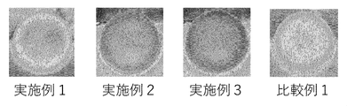
口金21から排出された直後のセラミックスハニカム成形体の温度分布を赤外線サーモグラフィカメラ(日本アビオニクス株式会社製Thermo GEAR G120EX)を用いて測定した。温度分布の結果は、セラミックスハニカム成形体の押出方向に垂直な断面全体の結果を図6に示す。また、セラミックスハニカム成形体の押出方向に垂直な断面の外周部及び中心部の温度を表1に示す。
口金21から排出された直後のセラミックスハニカム成形体の温度分布を赤外線サーモグラフィカメラ(日本アビオニクス株式会社製Thermo GEAR G120EX)を用いて測定した。温度分布の結果は、セラミックスハニカム成形体の押出方向に垂直な断面全体の結果を図6に示す。また、セラミックスハニカム成形体の押出方向に垂直な断面の外周部及び中心部の温度を表1に示す。
(真円度)
デジタルノギスを用いてセラミックスハニカム成形体の真円度を測定した。その結果を表1に示す。
デジタルノギスを用いてセラミックスハニカム成形体の真円度を測定した。その結果を表1に示す。
(成形体端面の凸量)
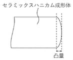
口金21から排出された直後のセラミックスハニカム成形体を押出方向と垂直な方向に切断した後、その切断面を押出方向と垂直な方向から写真撮影し、成形体端面の凸量を測定した。凸量の測定は、撮影写真において、2つの外周端面部を繋ぐ直線を引き、当該直線に対して隆起している凸部の距離を求めることによって行なった。撮影写真から凸量の測定方法を説明するための模式図を図7に示す。その結果を表1に示す。
口金21から排出された直後のセラミックスハニカム成形体を押出方向と垂直な方向に切断した後、その切断面を押出方向と垂直な方向から写真撮影し、成形体端面の凸量を測定した。凸量の測定は、撮影写真において、2つの外周端面部を繋ぐ直線を引き、当該直線に対して隆起している凸部の距離を求めることによって行なった。撮影写真から凸量の測定方法を説明するための模式図を図7に示す。その結果を表1に示す。

表1及び図6に示されるように、断熱部材40を有する実施例1の押出成形機1は、断熱部材40を有していない比較例1の押出成形機に比べて、成形体の温度分布が均一であり、真円度が良好で凸量が少ない成形体を与えた。
また、温度調節手段24aを追加した実施例2の押出成形機2は、実施例1の押出成形機1に比べて、真円度及び凸量の結果が良好な成形体を与えた。
さらに、温度調節手段24bを更に追加した実施例3の押出成形機2は、実施例2の押出成形機2に比べて、真円度及び凸量の結果がより良好な成形体を与えた。
また、温度調節手段24aを追加した実施例2の押出成形機2は、実施例1の押出成形機1に比べて、真円度及び凸量の結果が良好な成形体を与えた。
さらに、温度調節手段24bを更に追加した実施例3の押出成形機2は、実施例2の押出成形機2に比べて、真円度及び凸量の結果がより良好な成形体を与えた。
以上の結果からわかるように、本発明によれば、寸法精度が高い成形体を製造することができる押出成形機を提供することができる。また、本発明によれば、寸法精度が高い成形体の製造方法を提供することができる。
1、2、3 押出成形機
10 押出部
11 スクリュー
12 バレル
13 押出口
14 スクリュー軸
15 羽根部
16 駆動装置
17 材料投入部
20 成形部
21 口金
22 ドラム
23 スクリーン
24a、24b 温度調節手段
25 温度調節ドラム
26 供給口
27 排出口
28 拡径ドラム
29 ストレートドラム
30 整流板
40 断熱部材
41 貫通孔
50 保護部材
10 押出部
11 スクリュー
12 バレル
13 押出口
14 スクリュー軸
15 羽根部
16 駆動装置
17 材料投入部
20 成形部
21 口金
22 ドラム
23 スクリーン
24a、24b 温度調節手段
25 温度調節ドラム
26 供給口
27 排出口
28 拡径ドラム
29 ストレートドラム
30 整流板
40 断熱部材
41 貫通孔
50 保護部材
Claims (12)
- スクリュー、及び前記スクリューを収容可能なバレルを有する押出部と、
一端に口金を有し、他端が前記押出部の押出口に接続された成形部と、
前記押出部と前記成形部との間に配置された整流板と
を備える押出成形機であって、
前記成形部と前記整流板との間に断熱部材が配置されている押出成形機。 - 前記断熱部材の熱伝導率が0.5W/m・K以下である、請求項1に記載の押出成形機。
- 押出方向における前記断熱部材の厚さが1~50mmである、請求項1又は2に記載の押出成形機。
- 前記断熱部材が断熱性樹脂から形成されている、請求項1~3のいずれか一項に記載の押出成形機。
- 前記成形部と前記整流板との間の成形材料と接する位置に、前記断熱部材を保護するための保護部材が配置されている、請求項4に記載の押出成形機。
- 前記成形部に温度調節手段が設けられている、請求項1~5のいずれか一項に記載の押出成形機。
- 前記成形部内にスクリーンが設けられており、前記スクリーンと前記口金との間に前記温度調節手段が設けられている、請求項6に記載の押出成形機。
- 前記成形部が拡径部を有し、前記拡径部に前記温度調節手段が設けられている、請求項6又は7に記載の押出成形機。
- 前記温度調節手段が、内部を流体が流通可能な温度調節ドラムである、請求項6~8のいずれか一項に記載の押出成形機。
- 前記成形部の外周が断熱シートで被覆されている、請求項1~9のいずれか一項に記載の押出成形機。
- セラミックス成形体の製造に用いられる、請求項1~10のいずれか一項に記載の押出成形機。
- 請求項1~11のいずれか一項に記載の押出成形機を用いて成形材料を成形する成形体の製造方法。
Priority Applications (5)
| Application Number | Priority Date | Filing Date | Title |
|---|---|---|---|
| DE112019003467.7T DE112019003467T5 (de) | 2019-04-10 | 2019-04-10 | Strangpressmaschine und Verfahren zur Herstellung eines Formkörpers |
| CN201980028013.0A CN112074386B (zh) | 2019-04-10 | 2019-04-10 | 挤出成型机以及成型体的制造方法 |
| PCT/JP2019/015687 WO2020208753A1 (ja) | 2019-04-10 | 2019-04-10 | 押出成形機、及び成形体の製造方法 |
| JP2019557882A JP6788130B1 (ja) | 2019-04-10 | 2019-04-10 | 押出成形機、及びセラミックス成形体の製造方法 |
| US17/132,323 US20210107178A1 (en) | 2019-04-10 | 2020-12-23 | Extrusion molding machine, and method for producing molded body |
Applications Claiming Priority (1)
| Application Number | Priority Date | Filing Date | Title |
|---|---|---|---|
| PCT/JP2019/015687 WO2020208753A1 (ja) | 2019-04-10 | 2019-04-10 | 押出成形機、及び成形体の製造方法 |
Related Child Applications (1)
| Application Number | Title | Priority Date | Filing Date |
|---|---|---|---|
| US17/132,323 Continuation US20210107178A1 (en) | 2019-04-10 | 2020-12-23 | Extrusion molding machine, and method for producing molded body |
Publications (1)
| Publication Number | Publication Date |
|---|---|
| WO2020208753A1 true WO2020208753A1 (ja) | 2020-10-15 |
Family
ID=72751199
Family Applications (1)
| Application Number | Title | Priority Date | Filing Date |
|---|---|---|---|
| PCT/JP2019/015687 Ceased WO2020208753A1 (ja) | 2019-04-10 | 2019-04-10 | 押出成形機、及び成形体の製造方法 |
Country Status (5)
| Country | Link |
|---|---|
| US (1) | US20210107178A1 (ja) |
| JP (1) | JP6788130B1 (ja) |
| CN (1) | CN112074386B (ja) |
| DE (1) | DE112019003467T5 (ja) |
| WO (1) | WO2020208753A1 (ja) |
Cited By (2)
| Publication number | Priority date | Publication date | Assignee | Title |
|---|---|---|---|---|
| JP2022134081A (ja) * | 2021-03-02 | 2022-09-14 | 日本碍子株式会社 | 導電性ハニカム構造体の製造方法及び電気加熱式担体の製造方法 |
| JP2023149427A (ja) * | 2022-03-31 | 2023-10-13 | 日本碍子株式会社 | ハニカム構造体、その製造方法、およびハニカム成形体の形状調整方法 |
Families Citing this family (2)
| Publication number | Priority date | Publication date | Assignee | Title |
|---|---|---|---|---|
| CN114290489A (zh) * | 2021-12-22 | 2022-04-08 | 凯龙蓝烽新材料科技有限公司 | 一种新型挤出机头构造 |
| KR102439640B1 (ko) * | 2022-05-25 | 2022-09-01 | 심언규 | 벽돌 제조장치 |
Citations (4)
| Publication number | Priority date | Publication date | Assignee | Title |
|---|---|---|---|---|
| JPS61241105A (ja) * | 1985-04-18 | 1986-10-27 | 株式会社ノリタケカンパニーリミテド | スクリユ−式押出機または混練機 |
| JP2001260116A (ja) * | 1999-02-26 | 2001-09-25 | Denso Corp | セラミック成形体の製造方法および製造装置 |
| JP2006289953A (ja) * | 2005-03-17 | 2006-10-26 | Ngk Insulators Ltd | ハニカム成形体の製造方法 |
| JP2017019126A (ja) * | 2015-07-08 | 2017-01-26 | 三菱電機株式会社 | 成形用金型、押出成形装置、押出成形方法 |
Family Cites Families (20)
| Publication number | Priority date | Publication date | Assignee | Title |
|---|---|---|---|---|
| US2078509A (en) * | 1934-02-13 | 1937-04-27 | Ind Rayon Corp | Spinneret |
| US2702408A (en) * | 1950-07-27 | 1955-02-22 | Union Carbide & Carbon Corp | Extrusion of thermoplastic materials |
| US3305893A (en) * | 1964-07-09 | 1967-02-28 | James F Machen | Extruder |
| US4746220A (en) * | 1985-04-18 | 1988-05-24 | Noritake Co., Limited | Screw type extruding or kneading machine and screw used therein |
| JPS62259805A (ja) * | 1986-05-07 | 1987-11-12 | バブコツク日立株式会社 | ハニカム押出成形装置の運転方法 |
| US4913863A (en) * | 1989-01-30 | 1990-04-03 | Hoechst Celanese Corporation | Split extrusion die assembly for thermoplastic materials and methods of using the same |
| CN1046868A (zh) * | 1989-05-03 | 1990-11-14 | 冯养正 | 直接水冷的塑料挤出定型方法 |
| JPH04324915A (ja) * | 1991-04-25 | 1992-11-13 | Seiko Epson Corp | 押出成形用金型 |
| US5360829A (en) * | 1991-07-12 | 1994-11-01 | Kanebo, Ltd. | Foamed polyester sheet and process for the production thereof |
| JPH1067042A (ja) * | 1996-08-29 | 1998-03-10 | Mitsui Petrochem Ind Ltd | 肉厚成形体の押出成形方法および押出成形装置 |
| KR100229235B1 (ko) * | 1997-03-12 | 1999-11-01 | 이정국 | 농업용 필름 조성물 |
| US6652257B2 (en) * | 1999-02-26 | 2003-11-25 | Denso Corporation | Apparatus for producing ceramic moldings |
| JP2007298814A (ja) * | 2006-05-01 | 2007-11-15 | Nitto Denko Corp | 定着ベルト及びその製造方法 |
| JP4909013B2 (ja) * | 2006-11-01 | 2012-04-04 | 日本碍子株式会社 | 二軸押出機 |
| US20160082628A1 (en) * | 2008-05-02 | 2016-03-24 | Industrial Science & Technology Network, Inc. | Advanced Thermal Insulation by Pore Morphology Control in Foaming |
| MX338500B (es) * | 2010-06-17 | 2016-04-20 | Sumitomo Chemical Co | Dispositivo de moldeo por extrusion y metodo para producir un cuerpo moldeado utilizando el mismo. |
| EP3053721A1 (en) * | 2013-10-04 | 2016-08-10 | Sumitomo Chemical Company Limited | Extrusion molding device and method for manufacturing green honeycomb molded body |
| CN109109255A (zh) * | 2017-06-23 | 2019-01-01 | 广东奔迪新材料科技有限公司 | 一种采用通用级聚丙烯挤出发泡成型的板材 |
| CN107498817A (zh) * | 2017-10-12 | 2017-12-22 | 黄石市鼎晟模具有限公司 | 一种具有防烫功能的塑胶挤出模具 |
| CN108891003A (zh) * | 2018-08-06 | 2018-11-27 | 芜湖市旭辉电工新材料有限责任公司 | 一种快速冷却的电缆绝缘挤出装置 |
-
2019
- 2019-04-10 WO PCT/JP2019/015687 patent/WO2020208753A1/ja not_active Ceased
- 2019-04-10 CN CN201980028013.0A patent/CN112074386B/zh active Active
- 2019-04-10 JP JP2019557882A patent/JP6788130B1/ja active Active
- 2019-04-10 DE DE112019003467.7T patent/DE112019003467T5/de active Pending
-
2020
- 2020-12-23 US US17/132,323 patent/US20210107178A1/en active Pending
Patent Citations (4)
| Publication number | Priority date | Publication date | Assignee | Title |
|---|---|---|---|---|
| JPS61241105A (ja) * | 1985-04-18 | 1986-10-27 | 株式会社ノリタケカンパニーリミテド | スクリユ−式押出機または混練機 |
| JP2001260116A (ja) * | 1999-02-26 | 2001-09-25 | Denso Corp | セラミック成形体の製造方法および製造装置 |
| JP2006289953A (ja) * | 2005-03-17 | 2006-10-26 | Ngk Insulators Ltd | ハニカム成形体の製造方法 |
| JP2017019126A (ja) * | 2015-07-08 | 2017-01-26 | 三菱電機株式会社 | 成形用金型、押出成形装置、押出成形方法 |
Cited By (4)
| Publication number | Priority date | Publication date | Assignee | Title |
|---|---|---|---|---|
| JP2022134081A (ja) * | 2021-03-02 | 2022-09-14 | 日本碍子株式会社 | 導電性ハニカム構造体の製造方法及び電気加熱式担体の製造方法 |
| JP7760319B2 (ja) | 2021-03-02 | 2025-10-27 | 日本碍子株式会社 | 導電性ハニカム構造体の製造方法及び電気加熱式担体の製造方法 |
| JP2023149427A (ja) * | 2022-03-31 | 2023-10-13 | 日本碍子株式会社 | ハニカム構造体、その製造方法、およびハニカム成形体の形状調整方法 |
| JP7817048B2 (ja) | 2022-03-31 | 2026-02-18 | 日本碍子株式会社 | ハニカム構造体、その製造方法、およびハニカム成形体の形状調整方法 |
Also Published As
| Publication number | Publication date |
|---|---|
| DE112019003467T5 (de) | 2021-05-06 |
| CN112074386A (zh) | 2020-12-11 |
| JPWO2020208753A1 (ja) | 2021-05-06 |
| JP6788130B1 (ja) | 2020-11-18 |
| US20210107178A1 (en) | 2021-04-15 |
| CN112074386B (zh) | 2021-12-14 |
Similar Documents
| Publication | Publication Date | Title |
|---|---|---|
| JP6788130B1 (ja) | 押出成形機、及びセラミックス成形体の製造方法 | |
| JP2009196303A (ja) | ニーディングディスクセグメント及び2軸押出機 | |
| CN104097251B (zh) | 用于挤出设备的混合件以及制造蜂窝结构的方法 | |
| JP4805372B2 (ja) | 押出成形装置および、それを用いた成形体の製造方法 | |
| US4364881A (en) | Continuous extrusion method of manufacturing ceramic honeycomb structures with the aid of screw type vacuum extruding machine | |
| JP2014184647A (ja) | 押出機の回転速度制御方法、及び、押出装置 | |
| US12097638B2 (en) | Extrusion molding machine and method for producing molded body | |
| JP4909013B2 (ja) | 二軸押出機 | |
| JP2022063787A (ja) | 押出成形機及び成形体の製造方法 | |
| JP2008137186A (ja) | セラミック成形体の押出成形装置 | |
| US2803042A (en) | Apparatus for extruding tubes of fibrous material | |
| JP2017149002A (ja) | 二軸押出機 | |
| JP7550310B2 (ja) | 共回転ツインスクリュー処理装置のための要素 | |
| JP6790313B1 (ja) | セラミックス成形体及びセラミックス構造体の製造方法 | |
| SU1172738A1 (ru) | Элемент подпора и смешени дл двухчерв чного экструдера | |
| CN216299908U (zh) | 一种pet化学发泡用双螺杆挤出机 | |
| JPH05237913A (ja) | 高混練スクリュ | |
| US20210162625A1 (en) | Extrusion apparatus for ceramic structures and honeycomb filters | |
| CN112959588A (zh) | 一种pet化学发泡材料、方法及发泡用双螺杆挤出机 | |
| JPH05253914A (ja) | セラミック坏土の押出成形法 | |
| US20140191444A1 (en) | Apparatuses and methods for extruding a block product from a feed material | |
| JPH0985804A (ja) | 2軸押出成形機用スクリュー | |
| JPH10225976A (ja) | 樹脂成形品の製造方法およびこの製造方法に用いる製造装置 | |
| JPS5861916A (ja) | 押出加工用ダイス | |
| JPS5913336B2 (ja) | 押出機用スクリユ− |
Legal Events
| Date | Code | Title | Description |
|---|---|---|---|
| ENP | Entry into the national phase |
Ref document number: 2019557882 Country of ref document: JP Kind code of ref document: A |
|
| 121 | Ep: the epo has been informed by wipo that ep was designated in this application |
Ref document number: 19924284 Country of ref document: EP Kind code of ref document: A1 |
|
| 122 | Ep: pct application non-entry in european phase |
Ref document number: 19924284 Country of ref document: EP Kind code of ref document: A1 |