WO2020204153A1 - Engin de chantier - Google Patents
Engin de chantier Download PDFInfo
- Publication number
- WO2020204153A1 WO2020204153A1 PCT/JP2020/015267 JP2020015267W WO2020204153A1 WO 2020204153 A1 WO2020204153 A1 WO 2020204153A1 JP 2020015267 W JP2020015267 W JP 2020015267W WO 2020204153 A1 WO2020204153 A1 WO 2020204153A1
- Authority
- WO
- WIPO (PCT)
- Prior art keywords
- state
- boom
- cylinder
- pair
- electric motor
- Prior art date
Links
- 230000007246 mechanism Effects 0.000 claims description 313
- 230000008878 coupling Effects 0.000 claims description 8
- 238000010168 coupling process Methods 0.000 claims description 8
- 238000005859 coupling reaction Methods 0.000 claims description 8
- 230000007704 transition Effects 0.000 description 49
- 238000001514 detection method Methods 0.000 description 46
- 230000005540 biological transmission Effects 0.000 description 36
- 230000033001 locomotion Effects 0.000 description 24
- 230000008602 contraction Effects 0.000 description 22
- 239000003638 chemical reducing agent Substances 0.000 description 19
- 238000010586 diagram Methods 0.000 description 14
- 230000001360 synchronised effect Effects 0.000 description 11
- 238000000034 method Methods 0.000 description 5
- 230000002093 peripheral effect Effects 0.000 description 5
- 239000000470 constituent Substances 0.000 description 4
- 230000005611 electricity Effects 0.000 description 4
- 210000000078 claw Anatomy 0.000 description 3
- 230000002265 prevention Effects 0.000 description 3
- 230000006872 improvement Effects 0.000 description 2
- 230000008569 process Effects 0.000 description 2
- 238000011000 absolute method Methods 0.000 description 1
- 230000009471 action Effects 0.000 description 1
- 230000000694 effects Effects 0.000 description 1
- 238000005259 measurement Methods 0.000 description 1
- 230000001105 regulatory effect Effects 0.000 description 1
- 230000004044 response Effects 0.000 description 1
- 238000011144 upstream manufacturing Methods 0.000 description 1
Images


Classifications
-
- B—PERFORMING OPERATIONS; TRANSPORTING
- B66—HOISTING; LIFTING; HAULING
- B66C—CRANES; LOAD-ENGAGING ELEMENTS OR DEVICES FOR CRANES, CAPSTANS, WINCHES, OR TACKLES
- B66C23/00—Cranes comprising essentially a beam, boom, or triangular structure acting as a cantilever and mounted for translatory of swinging movements in vertical or horizontal planes or a combination of such movements, e.g. jib-cranes, derricks, tower cranes
- B66C23/62—Constructional features or details
- B66C23/64—Jibs
- B66C23/70—Jibs constructed of sections adapted to be assembled to form jibs or various lengths
- B66C23/701—Jibs constructed of sections adapted to be assembled to form jibs or various lengths telescopic
- B66C23/706—Jibs constructed of sections adapted to be assembled to form jibs or various lengths telescopic telescoped by other means
-
- B—PERFORMING OPERATIONS; TRANSPORTING
- B66—HOISTING; LIFTING; HAULING
- B66C—CRANES; LOAD-ENGAGING ELEMENTS OR DEVICES FOR CRANES, CAPSTANS, WINCHES, OR TACKLES
- B66C23/00—Cranes comprising essentially a beam, boom, or triangular structure acting as a cantilever and mounted for translatory of swinging movements in vertical or horizontal planes or a combination of such movements, e.g. jib-cranes, derricks, tower cranes
- B66C23/62—Constructional features or details
- B66C23/64—Jibs
- B66C23/70—Jibs constructed of sections adapted to be assembled to form jibs or various lengths
- B66C23/701—Jibs constructed of sections adapted to be assembled to form jibs or various lengths telescopic
- B66C23/705—Jibs constructed of sections adapted to be assembled to form jibs or various lengths telescopic telescoped by hydraulic jacks
-
- B—PERFORMING OPERATIONS; TRANSPORTING
- B66—HOISTING; LIFTING; HAULING
- B66C—CRANES; LOAD-ENGAGING ELEMENTS OR DEVICES FOR CRANES, CAPSTANS, WINCHES, OR TACKLES
- B66C23/00—Cranes comprising essentially a beam, boom, or triangular structure acting as a cantilever and mounted for translatory of swinging movements in vertical or horizontal planes or a combination of such movements, e.g. jib-cranes, derricks, tower cranes
- B66C23/62—Constructional features or details
- B66C23/64—Jibs
- B66C23/70—Jibs constructed of sections adapted to be assembled to form jibs or various lengths
- B66C23/701—Jibs constructed of sections adapted to be assembled to form jibs or various lengths telescopic
- B66C23/708—Jibs constructed of sections adapted to be assembled to form jibs or various lengths telescopic locking devices for telescopic jibs
-
- E—FIXED CONSTRUCTIONS
- E02—HYDRAULIC ENGINEERING; FOUNDATIONS; SOIL SHIFTING
- E02F—DREDGING; SOIL-SHIFTING
- E02F3/00—Dredgers; Soil-shifting machines
- E02F3/04—Dredgers; Soil-shifting machines mechanically-driven
- E02F3/28—Dredgers; Soil-shifting machines mechanically-driven with digging tools mounted on a dipper- or bucket-arm, i.e. there is either one arm or a pair of arms, e.g. dippers, buckets
- E02F3/283—Dredgers; Soil-shifting machines mechanically-driven with digging tools mounted on a dipper- or bucket-arm, i.e. there is either one arm or a pair of arms, e.g. dippers, buckets with a single arm pivoted directly on the chassis
- E02F3/286—Dredgers; Soil-shifting machines mechanically-driven with digging tools mounted on a dipper- or bucket-arm, i.e. there is either one arm or a pair of arms, e.g. dippers, buckets with a single arm pivoted directly on the chassis telescopic or slidable
Definitions
- the present invention relates to a working machine provided with a telescopic boom.
- Patent Document 1 discloses a telescopic boom in which a plurality of boom elements are nested (also referred to as a telescopic shape), and a mobile crane including a hydraulic telescopic cylinder for extending the telescopic boom. There is.
- the telescopic boom has a boom connecting pin that connects adjacent and overlapping boom elements.
- the boom element hereinafter referred to as a movable boom element
- the boom connecting pin can move in the longitudinal direction (also referred to as expansion / contraction direction) with respect to other boom elements.
- the telescopic cylinder has a rod member and a cylinder member.
- a telescopic cylinder connects a cylinder member to the movable boom element via a cylinder connecting pin.
- the crane as described above includes a hydraulic actuator for moving the boom connecting pin, a hydraulic actuator for moving the cylinder connecting pin, and a hydraulic circuit for supplying pressure oil to each of these actuators.
- a hydraulic circuit is provided, for example, around a telescopic boom. This can reduce the degree of freedom in design around the telescopic boom.
- An object of the present invention is to provide a working machine capable of improving the degree of freedom in design around the telescopic boom.
- the working machine is Actuators that expand and contract the telescopic boom, and An electrical drive source provided in the actuator and driven based on the power supply from the power supply, An actuating part that operates based on the power of an electrical drive source, Braking that allows power supply from the power source to the electric drive source and drives the electric drive source, and stops power supply from the power source to the electric drive source to generate braking force applied to the electric drive source.
- An electric circuit that can switch between states and It is provided with a control unit that controls switching between a driving state and a braking state.
- the degree of freedom in design around the telescopic boom can be improved.
- FIG. 1 is a schematic view of a mobile crane according to an embodiment.
- 2A to 2E are schematic views for explaining the structure and expansion / contraction operation of the telescopic boom.
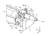
- FIG. 3A is a perspective view of the actuator.
- FIG. 3B is an enlarged view of part A of FIG. 3A.
- FIG. 4 is a partial plan view of the actuator.
- FIG. 5 is a partial side view of the actuator.
- Figure 6 is a A 1 arrow view of FIG.
- FIG. 7 is a perspective view of the pin moving module in a state where the boom connecting pin is held.
- FIG. 8 is a front view of the pin moving module in the expanded state and the state in which the boom connecting pin is held.
- Figure 9 is a A 2 arrow view of FIG.
- FIG. 10 is a A 3 arrow view of FIG. Figure 11 is a A 4 arrow view of FIG.
- FIG. 12 is a front view of the pin moving module in which the boom connecting mechanism is in the reduced state and the cylinder connecting mechanism is in the expanded state.
- FIG. 13 is a front view of the pin moving module in which the boom connecting mechanism is in the expanded state and the cylinder connecting mechanism is in the reduced state.
- FIG. 14A is a schematic diagram for explaining the operation of the lock mechanism.
- FIG. 14B is a schematic diagram for explaining the operation of the lock mechanism.
- FIG. 14C is a schematic diagram for explaining the operation of the lock mechanism.
- FIG. 14D is a schematic diagram for explaining the operation of the lock mechanism.
- FIG. 15A is a schematic diagram for explaining the operation of the locking mechanism.
- FIG. 15B is a schematic diagram for explaining the operation of the locking mechanism.
- FIG. 16A is a circuit diagram of an electric circuit in a non-energized state.
- FIG. 16B is a circuit diagram of an electric circuit in the first drive state.
- FIG. 16C is a circuit diagram of an electric circuit in the second drive state.
- FIG. 16D is a circuit diagram of an electric circuit in a braking state.
- FIG. 17 is a timing chart during the extension operation of the telescopic boom.
- FIG. 18A is a schematic view for explaining the operation of the cylinder connecting mechanism.
- FIG. 18B is a schematic diagram for explaining the operation of the cylinder connecting mechanism.
- FIG. 18C is a schematic diagram for explaining the operation of the cylinder connecting mechanism.
- FIG. 19A is a schematic view for explaining the operation of the boom connecting mechanism.
- FIG. 19B is a schematic diagram for explaining the operation of the boom connecting mechanism.
- FIG. 19C is a schematic diagram for explaining the operation of the boom
- FIG. 1 is a schematic view of a mobile crane 1 (rough terrain crane in the case of illustration) according to the present embodiment.
- the mobile crane 1 corresponds to an example of a working machine.
- mobile cranes examples include all-terrain cranes, truck cranes, and loaded truck cranes (also referred to as cargo cranes).
- the work machine according to the present invention is not limited to the mobile crane, and can be applied to other work vehicles (for example, cranes, aerial work platforms) having a telescopic boom.
- the mobile crane 1 includes a traveling body 10, an outrigger 11, a swivel base 12, a telescopic boom 14, an actuator 2 (omitted in FIG. 1), and an electric circuit 6 (FIG. 16A). (See FIG. 16D), an undulating cylinder 15, a wire 16, and a hook 17.
- the traveling body 10 has a plurality of wheels 101. Outriggers 11 are provided at the four corners of the traveling body 10.
- the swivel base 12 is provided on the upper portion of the traveling body 10 so as to be swivelable.
- the base end of the telescopic boom 14 is fixed to the swivel base 12.
- the actuator 2 expands and contracts the telescopic boom 14.
- the undulating cylinder 15 undulates the telescopic boom 14.
- the wire 16 hangs down from the tip of the telescopic boom 14.
- the hook 17 is provided at the tip of the wire 16.
- FIGS. 1 and 2A to 2E are schematic views for explaining the structure and expansion / contraction operation of the telescopic boom 14.
- FIG. 1 shows a telescopic boom 14 in an extended state.
- FIG. 2A shows a telescopic boom 14 in a contracted state.
- FIG. 2E shows a telescopic boom 14 in which only the tip boom element 141, which will be described later, is extended.
- the telescopic boom 14 is composed of a plurality of boom elements. Each of the boom elements is tubular. The boom elements are telescopically combined with each other. Specifically, in the contracted state, the plurality of boom elements are the tip boom element 141, the intermediate boom element 142, and the proximal boom element 143 in order from the inside.
- the tip boom element 141 and the intermediate boom element 142 correspond to an example of the first boom element that can move in the expansion / contraction direction.
- the tip boom element 141 moves in the expansion / contraction direction with respect to the intermediate boom element 142
- the tip boom element 141 corresponds to an example of the first boom element
- the intermediate boom element 142 corresponds to an example of the second boom element.
- the intermediate boom element 142 moves in the expansion / contraction direction with respect to the proximal boom element 143
- the intermediate boom element 142 corresponds to an example of the first boom element
- the proximal boom element 143 corresponds to the second boom.
- the base end boom element 143 is restricted from moving in the expansion / contraction direction.
- the intermediate boom element 142 is arranged between the proximal end boom element 143 on the most proximal end side and the distal boom element 141 on the most distal end side.
- the number of intermediate boom elements may be plural.
- the structure of the telescopic boom 14 is almost the same as the structure of the conventionally known telescopic boom, but for convenience of explanation regarding the structure and operation of the actuator 2 described later, the tip boom element 141 and the intermediate boom are described below. The structure of the element 142 will be described.
- the tip boom element 141 has a tubular shape as shown in FIGS. 2A to 2E.
- the tip boom element 141 has an internal space that can accommodate the actuator 2.
- the tip boom element 141 has a pair of cylinder pin receiving portions 141a and a pair of boom pin receiving portions 141b at the base end portion.
- the pair of cylinder pin receiving portions 141a are provided coaxially with each other at the base end portion of the tip boom element 141.
- Each of the pair of cylinder pin receiving portions 141a can be engaged with and detached from the pair of cylinder connecting pins 454a and 454b (also referred to as the first connecting member) provided in the cylinder member 32 of the telescopic cylinder 3. That is, either the pair of cylinder pin receiving portions 141a is engaged with the pair of cylinder connecting pins 454a and 454b, or the pair of cylinder pin receiving portions 141a is disengaged with the pair of cylinder connecting pins 454a and 454b. It can take one state.
- the cylinder connecting pins 454a and 454b move in their own axial direction based on the operation of the cylinder connecting mechanism 45 included in the actuator 2 described later. With the pair of cylinder connecting pins 454a and 454b engaged with the pair of cylinder pin receiving portions 141a, the tip boom element 141 can move in the expansion / contraction direction together with the cylinder member 32.
- the pair of boom pin receiving portions 141b are provided coaxially with each other on the proximal end side of the cylinder pin receiving portion 141a.
- Each of the boom pin receiving portions 141b can be engaged with and detached from the pair of boom connecting pins 144a (also referred to as a second connecting member). That is, the pair of boom pin receiving portions 141b takes either an engaged state of engaging with the pair of boom connecting pins 144a and a disengaged state of being disengaged with the pair of boom connecting pins 144a. obtain.
- the pair of boom connecting pins 144a connect the tip boom element 141 and the intermediate boom element 142, respectively.
- the pair of boom connecting pins 144a move in their own axial direction based on the operation of the boom connecting mechanism 46 included in the actuator 2.
- the pair of boom connecting pins 144a may be regarded as constituent members of the boom connecting mechanism 46.
- the boom pin receiving portion 141b of the tip boom element 141 and the first boom pin receiving portion 142b or the first boom pin receiving portion 142b of the intermediate boom element 142 described later The boom connecting pin 144a is inserted through the boom pin receiving portion 142c so as to be bridged.
- the tip boom element 141 In a state where the tip boom element 141 and the intermediate boom element 142 are connected (also referred to as a connected state), the tip boom element 141 is prohibited from moving in the expansion / contraction direction with respect to the intermediate boom element 142.
- the tip boom element 141 in a state where the tip boom element 141 and the intermediate boom element 142 are disconnected (also referred to as a non-connected state), the tip boom element 141 can move in the expansion / contraction direction with respect to the intermediate boom element 142.
- the intermediate boom element 142 has a tubular shape as shown in FIGS. 2A to 2E.
- the intermediate boom element 142 has an internal space capable of accommodating the tip boom element 141.
- the intermediate boom element 142 has a pair of cylinder pin receiving portions 142a, a pair of first boom pin receiving portions 142b, a pair of second boom pin receiving portions 142c, and a pair of third boom pin receiving portions 142d at the base end portion.
- the pair of cylinder pin receiving portions 142a and the pair of first boom pin receiving portions 142b are substantially the same as the pair of cylinder pin receiving portions 141a and the pair of boom pin receiving portions 141b of the tip boom element 141, respectively.
- the pair of third boom pin receiving portions 142d are provided coaxially with each other on the proximal end side of the pair of first boom pin receiving portions 142b.
- a pair of boom connecting pins 144b are inserted into each of the pair of third boom pin receiving portions 142d.
- the pair of boom connecting pins 144b connect the intermediate boom element 142 and the proximal boom element 143.
- the pair of second boom pin receiving portions 142c are provided coaxially with each other at the tip portion of the intermediate boom element 142.
- a pair of boom connecting pins 144a are inserted into each of the pair of second boom pin receiving portions 142c.
- the actuator 2 is an actuator that expands and contracts the telescopic boom 14 (see FIGS. 1 and 2A to 2E) as described above.
- the actuator 2 has a telescopic cylinder 3 and a pin moving module 4.
- the actuator 2 is arranged in the internal space of the tip boom element 141 in the contracted state (state shown in FIG. 2A) of the telescopic boom 14.
- the telescopic cylinder 3 has a rod member 31 (also referred to as a fixed side member; see FIGS. 2A to 2E) and a cylinder member 32 (also referred to as a movable side member).
- the telescopic cylinder 3 moves the boom element (for example, the tip boom element 141 or the intermediate boom element 142) connected to the cylinder member 32 via the cylinder connecting pins 454a and 454b described later in the telescopic direction. Since the structure of the telescopic cylinder 3 is almost the same as the structure of the conventionally known telescopic cylinder, detailed description thereof will be omitted.
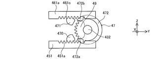
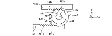
- the pin moving module 4 includes a housing 40, an electric motor 41, a brake mechanism 42, a transmission mechanism 43, a position information detection device 44, a cylinder connecting mechanism 45, a boom connecting mechanism 46, and a locking mechanism 47 (see FIG. 7).
- each member constituting the actuator 2 will be described with reference to the state of being incorporated in the actuator 2. Further, in the description of the actuator 2, the Cartesian coordinate system (X, Y, Z) shown in each figure is used. However, the arrangement of each part constituting the actuator 2 is not limited to the arrangement of the present embodiment.
- the X direction coincides with the expansion / contraction direction of the telescopic boom 14 mounted on the mobile crane 1.
- the + side in the X direction is also referred to as an extension direction in the expansion / contraction direction.
- the X direction-side is also referred to as a contraction direction in the expansion / contraction direction.
- the Z direction coincides with the vertical direction of the mobile crane 1 in a state where the undulation angle of the telescopic boom 14 is zero (also referred to as an undulating state of the telescopic boom 14), for example.
- the Y direction coincides with the vehicle width direction of the mobile crane 1, for example, when the telescopic boom 14 faces forward.
- the Y direction and the Z direction are not limited to the above-mentioned directions as long as they are two directions orthogonal to each other.
- the housing 40 is fixed to the cylinder member 32 of the telescopic cylinder 3.
- the housing 40 accommodates the cylinder connecting mechanism 45 and the boom connecting mechanism 46 in the internal space.
- the housing 40 supports the electric motor 41 via a transmission mechanism 43. Further, the housing 40 also supports the brake mechanism 42 described later.
- each of the above-mentioned elements is unitized. Such a configuration contributes to the miniaturization of the pin movement module 4, the improvement of productivity, and the improvement of the reliability of the system.
- the housing 40 has a box-shaped first housing element 400 and a box-shaped second housing element 401.
- the first housing element 400 accommodates a cylinder connecting mechanism 45, which will be described later, in an internal space.
- a rod member 31 is inserted through the first housing element 400 in the X direction.
- the end of the cylinder member 32 is fixed to the side wall of the first housing element 400 on the + side in the X direction (left side in FIG. 4 and right side in FIG. 7).
- the first housing element 400 has through holes 400a and 400b (see FIGS. 3B and 7) on the side walls on both sides in the Y direction.
- a pair of cylinder connecting pins 454a and 454b of the cylinder connecting mechanism 45 are inserted into the through holes 400a and 400b, respectively.
- the second housing element 401 is provided on the Z direction + side of the first housing element 400.
- the second housing element 401 accommodates a boom connecting mechanism 46, which will be described later, in an internal space.
- a transmission shaft 432 (see FIG. 8) of the transmission mechanism 43 described later is inserted through the second housing element 401 in the X direction.
- the second housing element 401 has through holes 401a and 401b (see FIGS. 3B and 7) on the side walls on both sides in the Y direction.
- a pair of second rack bars 461a and 461b of the boom connecting mechanism 46 are inserted into the through holes 401a and 401b, respectively.
- the electric motor 41 corresponds to an example of an electric drive source, and is supported by a housing 40 via a speed reducer 431 of a transmission mechanism 43. Specifically, the electric motor 41 is in a state where the output shaft (not shown) is parallel to the X direction (also referred to as the longitudinal direction of the cylinder member 32), and is around the cylinder member 32 (for example, the Z direction + side). It is arranged around the second housing element 401 (for example, the X direction-side). Such an arrangement contributes to the miniaturization of the pin movement module 4 in the Y direction and the Z direction.
- the electric motor 41 as described above is connected to, for example, a power supply device 61 (see FIGS. 16A to 16D) provided on the swivel base 12 via a power supply cable. Further, the electric motor 41 is connected to, for example, a control unit 44b (see FIG. 1) provided on the swivel base 12 via a cable for transmitting a control signal.
- Each of the above cables can be unwound and wound by a cord reel provided outside the base end of the telescopic boom 14 or on the swivel base 12 (see FIG. 1).
- the electric motor 41 has a manual operation unit 410 (see FIG. 3B) that can be operated by a manual handle (not shown).
- the manual operation unit 410 is for manually performing the state transition of the pin movement module 4.
- the output shaft of the electric motor 41 rotates and the state of the pin movement module 4 changes.
- the number of electric motors may be one or a plurality (for example, two).
- the cylinder connecting mechanism 45 and the boom connecting mechanism 46 are operated by one electric motor 41 as in the present embodiment.
- the cylinder connecting mechanism 45 is operated by the first electric motor (not shown)
- the boom connecting mechanism 46 is operated by the second electric motor (not shown). You can.
- the electric drive source is the electric motor 41 described above.
- the electric drive source is not limited to the electric motor.
- the electrical drive source may be various drive sources that generate a driving force based on energization from a power source.
- the brake mechanism 42 applies a braking force to the electric motor 41.
- the brake mechanism 42 prevents the rotation of the output shaft of the electric motor 41 when the electric motor 41 is stopped. As a result, the state of the pin moving module 4 is maintained in the stopped state of the electric motor 41.
- the brake mechanism 42 may allow the electric motor 41 to rotate (that is, slip) when an external force of a predetermined magnitude acts on the cylinder connecting mechanism 45 or the boom connecting mechanism 46 during braking.
- Such a configuration contributes to prevention of damage to the electric motor 41 and each gear constituting the actuator 2.
- a friction brake can be adopted as the brake mechanism 42.
- the brake mechanism 42 operates in the reduced state of the cylinder connecting mechanism 45 or the reduced state of the boom connecting mechanism 46, which will be described later, and maintains the states of the cylinder connecting mechanism 45 and the boom connecting mechanism 46.
- the brake mechanism 42 is arranged in front of the transmission mechanism 43 described later. Specifically, the brake mechanism 42 is arranged coaxially with the output shaft of the electric motor 41 on the X-direction-side of the electric motor 41 (that is, on the side opposite to the transmission mechanism 43 with the electric motor 41 as the center). (See FIG. 3B).
- the front stage means the upstream side (the side closer to the electric motor 41) in the transmission path in which the power of the electric motor 41 is transmitted to the cylinder connecting mechanism 45 or the boom connecting mechanism 46.
- the latter stage means the downstream side (the side far from the electric motor 41) in the transmission path in which the power of the electric motor 41 is transmitted to the cylinder connecting mechanism 45 or the boom connecting mechanism 46.
- the brake torque required to maintain the stopped state of the electric motor 41 is such that the brake mechanism 42 is arranged in front of the transmission mechanism 43, and the brake mechanism 42 is the transmission mechanism 43 (reducer 431 described later). It is smaller than the configuration arranged later than. For this reason, the configuration in which the brake mechanism 42 is arranged in front of the transmission mechanism 43 contributes to the miniaturization of the brake mechanism 42.
- the brake mechanism 42 may be various brake devices such as a mechanical type or an electromagnetic type. Further, the position of the brake mechanism 42 is not limited to the position of the present embodiment.
- the transmission mechanism 43 transmits the power (that is, rotational motion) of the electric motor 41 to the cylinder connecting mechanism 45 and the boom connecting mechanism 46.
- the transmission mechanism 43 has a speed reducer 431 and a transmission shaft 432 (see FIG. 8).
- the speed reducer 431 decelerates the rotation of the electric motor 41 and transmits it to the transmission shaft 432.
- the speed reducer 431 is, for example, a planetary gear mechanism housed in the speed reducer case 431a.
- the speed reducer 431 is provided coaxially with the output shaft of the electric motor 41. Such an arrangement contributes to the miniaturization of the pin movement module 4 in the Y direction and the Z direction.
- the end of the transmission shaft 432 on the X direction-side is connected to the output shaft (not shown) of the speed reducer 431. In this state, the transmission shaft 432 rotates together with the output shaft of the speed reducer 431.
- the transmission shaft 432 extends in the X direction and is inserted into the housing 40 (specifically, the second housing element 401).
- the transmission shaft 432 may be integrated with the output shaft of the speed reducer 431.
- the end of the transmission shaft 432 on the X direction + side protrudes from the housing 40 on the X direction + side.
- a position information detection device 44 which will be described later, is provided at the end of the transmission shaft 432 on the + side in the X direction.
- the position information detection device 44 may be a pair of cylinder connecting pins 454a and 454b and a pair of boom connecting pins 144a (a pair of boom connecting pins 144b) based on the output of the electric motor 41 (for example, rotation of the output shaft). , Same.) Detect information about the location.
- the information regarding the position may be, for example, the amount of movement of the pair of cylinder connecting pins 454a, 454b or the pair of boom connecting pins 144a from the reference position (positions shown in FIGS. 18A and 19A).
- 18A and 19A are defined as the reference positions of the cylinder connecting pins 454a and 454b. Further, the positions of the pair of boom connecting pins 144a shown in FIGS. 18A and 19A are defined as the reference positions of the boom connecting pins 144a.
- the position information detection device 44 engages a pair of cylinder connecting pins 454a and 454b with a pair of cylinder pin receiving portions 141a of the boom element (for example, the tip boom element 141) (for example, FIG. 2A). Information about the positions of the pair of cylinder connecting pins 454a and 454b in the state shown in (1) or the detached state (the state shown in FIG. 2E) is detected.
- the position information detection device 44 may be a pair of boom connecting pins 144a and a pair of first boom pin receiving portions 142b (a pair of second boom pin receiving portions 142c) of the boom element (for example, the intermediate boom element 142).
- Information about the position of the pair of boom connecting pins 144a in the engaged state (for example, the state shown in FIGS. 2A and 2D) or the disengaged state (for example, the state shown in FIG. 2B) with the same) is detected.
- the information regarding the positions of the pair of cylinder connecting pins 454a and 454b and the pair of boom connecting pins 144a and 144b detected in this way is used for various controls of the actuator 2 including, for example, operation control of the electric motor 41.
- the position information detection device 44 has a detection unit 44a and a control unit 44b (see FIGS. 18A and 18A).
- the detection unit 44a is, for example, a rotary encoder and outputs information (for example, a pulse signal or a code signal) according to the amount of rotation of the output shaft of the electric motor 41.
- the output method of the rotary encoder is not particularly limited, and an incremental method that outputs a pulse signal (relative angle signal) according to the amount of rotation (rotation angle) from the measurement start position may be used, or an absolute angle with respect to the reference point.
- An absolute method that outputs a code signal (absolute angle signal) corresponding to the position may be used.
- the position information detection device 44 can connect the pair of cylinder connecting pins 454a and 454b and the pair of booms even when the control unit 44b returns from the non-energized state to the energized state. Information about the position of pin 144a can be detected.
- the detection unit 44a may be provided on the output shaft of the electric motor 41. Further, the detection unit 44a may be provided on a rotating member (for example, a rotating shaft, a gear, etc.) that rotates together with the output shaft of the electric motor 41. Specifically, in the case of the present embodiment, the detection unit 44a is provided at the end of the transmission shaft 432 on the X direction + side. In other words, in the case of the present embodiment, the detection unit 44a is provided after the speed reducer 431 (that is, on the + side in the X direction).
- the detection unit 44a outputs information according to the amount of rotation of the transmission shaft 432.
- a rotary encoder capable of obtaining sufficient resolution with respect to the rotation speed (rotation speed) of the transmission shaft 432 is adopted. Since the first missing tooth gear 450 of the cylinder connecting mechanism 45 and the second missing tooth gear 460 of the boom connecting mechanism 46 are fixed to the transmission shaft 432, the output information of the detection unit 44a is obtained. It is also information according to the amount of rotation of the first missing tooth gear 450 and the second missing tooth gear 460.
- the detection unit 44a having the above configuration sends the detection value to the control unit 44b.
- the control unit 44b that has acquired the information calculates information regarding the positions of the pair of cylinder connecting pins 454a and 454b or the pair of boom connecting pins 144a based on the acquired information. Then, the control unit 44b controls the electric motor 41 based on the calculation result.
- the control unit 44b is an in-vehicle computer composed of, for example, an input terminal, an output terminal, a CPU, and a memory.
- the control unit 44b calculates information regarding the positions of the pair of cylinder connecting pins 454a and 454b or the boom connecting pin 144a based on the output of the detecting unit 44a.
- control unit 44b receives information on the output of the detection unit 44a and the positions of the pair of cylinder connecting pins 454a and 454b and the pair of boom connecting pins 144a (for example, the amount of movement from the reference position). Information on the above positions is calculated using data showing the correlation (table, map, etc.).
- the control unit 44b as described above is provided on the swivel base 12.
- the position of the control unit 44b is not limited to the swivel base 12.
- the control unit 44b may be provided, for example, in a case (not shown) in which the detection unit 44a is arranged.
- the position of the detection unit 44a is not limited to the position of the present embodiment.
- the detection unit 44a may be arranged in front of the speed reducer 431 (that is, on the X-direction-side). That is, the detection unit 44a may acquire information to be transmitted to the control unit 44b based on the rotation of the electric motor 41 before being decelerated by the speed reducer 431.
- the resolution of the detection unit 44a is higher in the configuration in which the detection unit 44a is arranged in the front stage of the speed reducer 431 than in the configuration in which the detection unit 44a is arranged in the rear stage of the speed reducer 431.
- the detection unit 44a is not limited to the rotary encoder described above.
- the detection unit 44a may be a limit switch.
- the limit switch is arranged after the speed reducer 431. Such a limit switch operates mechanically based on the output of the electric motor 41.
- the detection unit 44a may be a proximity sensor.
- the proximity sensor is arranged after the speed reducer 431. Further, the proximity sensor is arranged so as to face the member that rotates based on the output of the electric motor 41. Such a proximity sensor outputs a signal based on the distance to the rotating member. Then, the control unit 44b controls the operation of the electric motor 41 based on the output of the limit switch or the proximity sensor.
- the cylinder connecting mechanism 45 corresponds to an example of an operating unit, operates based on the power (that is, rotational motion) of the electric motor 41, and operates in an expanded state (also referred to as a first state, see FIGS. 8 and 12) and contracted. A state transition is made between the state (also referred to as the second state, see FIG. 13).
- the pair of cylinder connecting pins 454a and 454b which will be described later, and the pair of cylinder pin receiving portions 141a of the boom element (for example, the tip boom element 141) are engaged (also referred to as a cylinder pin inserted state). Will be.
- the boom element and the cylinder member 32 are connected.
- the cylinder connecting mechanism 45 includes a first missing tooth gear 450, a first rack bar 451, a first gear mechanism 452, a second gear mechanism 453, and a pair of cylinder connecting pins 454a and 454b. It also has a first urging mechanism 455.
- Each of the above elements 450, 451 and 452, 453 corresponds to an example of a constituent member of the first drive mechanism.
- a pair of cylinder connecting pins 454a and 454b are incorporated in the cylinder connecting mechanism 45.
- the pair of cylinder connecting pins 454a and 454b may be provided independently of the cylinder connecting mechanism 45.
- the first missing tooth gear 450 (also referred to as a switch gear) has a substantially annular plate shape.
- the first missing tooth gear 450 has a first tooth portion 450a (see FIG. 9) on a part of the outer peripheral surface.
- the first missing tooth gear 450 is fitted and fixed to the transmission shaft 432 and rotates together with the transmission shaft 432.
- Such a first missing tooth gear 450 constitutes a switch gear together with a second missing tooth gear 460 (see FIG. 8) of the boom connecting mechanism 46.
- the switch gear selectively transmits the power of the electric motor 41 to one of the cylinder connecting mechanism 45 and the boom connecting mechanism 46.
- first missing tooth gear 450 and the second missing tooth gear 460 which are switch gears
- the cylinder connecting mechanism 45 which is the first connecting mechanism
- the boom connecting mechanism 46 which is the second connecting mechanism
- the switch gear may be provided independently of the first connecting mechanism and the second connecting mechanism.
- the rotational direction (the direction indicated by arrow F 2 in Figure 18A ⁇ FIG 18C) is the "front side" in the rotational direction of the first toothless gear 450.
- the rotation direction of the first missing tooth gear 450 (the direction indicated by the arrow F 1 in FIGS. 18A to 18C) when the state transitions from the reduced state to the expanded state is the rotation direction of the first missing tooth gear 450. Is the "rear side" of.
- the convex portion provided on the frontmost side in the rotation direction of the first missing tooth gear 450 is a positioning tooth (not shown).
- the first rack bar 451 moves in its own longitudinal direction (also referred to as the Y direction) in accordance with the rotation of the first missing tooth gear 450.
- the first rack bar 451 is located on the most Y-direction-side in the expanded state (see FIGS. 8 and 12).
- the first rack bar 451 is located on the + side in the Y direction most in the reduced state (see FIG. 13).
- the first rack bar 451 moves in the Y direction + side (also referred to as one in the longitudinal direction).
- the first rack bar 451 is also referred to as the Y direction ⁇ side (also referred to as the other in the longitudinal direction).
- the first rack bar 451 will be described.
- the first rack bar 451 is, for example, a shaft member long in the Y direction, and is arranged between the first missing tooth gear 450 and the rod member 31. In this state, the longitudinal direction of the first rack bar 451 coincides with the Y direction.
- the first rack bar 451 has a first rack tooth portion 451a (see FIG. 8) on a surface close to the first missing tooth gear 450 (also referred to as a Z direction + side).
- the first rack tooth portion 451a meshes with the first tooth portion 450a of the first missing tooth gear 450 only at the time of the above-mentioned state transition.
- the first end surface (not shown) on the Y direction + side of the first rack tooth portion 451a is a positioning tooth (not shown) in the first tooth portion 450a of the first missing tooth gear 450. ), Or faces in the Y direction through a slight gap.
- the tooth portion existing on the rear side in the rotation direction with respect to the positioning tooth meshes with the first rack tooth portion 451a.
- the first rack bar 451 moves in the Y direction + side in accordance with the rotation of the first missing tooth gear 450.
- the first missing tooth gear 450 rotates to the rear side in the rotation direction from the expanded state shown in FIG. 8, the first rack tooth portion 451a and the first tooth portion 450a of the first missing tooth gear 450 are different from each other. Does not mesh.
- the first rack bar 451 has a second rack tooth portion 451b and a third rack tooth portion 451c (see FIG. 8) on a surface far from the first missing tooth gear 450 (also referred to as a Z direction-side). Have.
- the second rack tooth portion 451b meshes with the first gear mechanism 452 described later.
- the third rack tooth portion 451c meshes with the second gear mechanism 453 described later.
- the first gear mechanism 452 includes a plurality of (three in the case of the present embodiment) gear elements 452a, 452b, and 452c (see FIG. 8), each of which is a spur gear.
- the gear element 452a meshes with the second rack tooth portion 451b and the gear element 452b of the first rack bar 451.
- the gear element 452a meshes with the tooth portion on the Y-direction + side end or the portion near the end of the second rack tooth portion 451b of the first rack bar 451.
- the gear element 452b meshes with the gear element 452a and the gear element 452c.
- the gear element 452c meshes with the gear element 452b and the pin-side rack tooth portion 454c of one of the cylinder connecting pins 454a described later. In the expanded state, the gear element 452c meshes with the end on the Y-side ⁇ side of the pin-side rack tooth portion 454c (see FIG. 8) of one cylinder connecting pin 454a.
- the second gear mechanism 453 includes a plurality of (two in the case of the present embodiment) gear elements 453a and 453b (see FIG. 8), each of which is a spur gear.
- the gear element 453a meshes with the third rack tooth portion 451c and the gear element 453b of the first rack bar 451.
- the gear element 453a meshes with the Y-direction + side end of the third rack tooth portion 451c of the first rack bar 451.
- the gear element 453b meshes with the gear element 453a and the pin-side rack tooth portion 454d (see FIG. 8) of the other cylinder connecting pin 454b described later. In the expanded state, the gear element 453b meshes with the Y-direction + side end of the pin-side rack tooth portion 454d of the other cylinder connecting pin 454b.
- the rotation direction of the gear element 452c of the first gear mechanism 452 and the rotation direction of the gear element 453b of the second gear mechanism 453 are opposite directions.
- ⁇ Cylinder connecting pin> The central axes of the pair of cylinder connecting pins 454a and 454b coincide with each other in the Y direction and are coaxial with each other.
- the tip end portion is an end portion on the side far from each other
- the base end portion is an end portion on the side close to each other.
- the pair of cylinder connecting pins 454a and 454b each have pin-side rack teeth 454c and 454d (see FIG. 8) on the outer peripheral surface.
- the pin-side rack tooth portion 454c of the cylinder connecting pin 454a (also referred to as the + side in the Y direction) meshes with the gear element 452c of the first gear mechanism 452.
- One of the cylinder connecting pins 454a moves in its own axial direction (that is, in the Y direction) as the gear element 452c in the first gear mechanism 452 rotates. Specifically, one of the cylinder connecting pins 454a moves in the Y direction + side (also referred to as the second direction) when the state transitions from the reduced state to the expanded state. On the other hand, one cylinder connecting pin 454a moves in the Y direction-side (also referred to as the first direction) when the state transitions from the expanded state to the contracted state.
- the pin-side rack tooth portion 454d of the cylinder connecting pin 454b meshes with the gear element 453b of the second gear mechanism 453.
- the other cylinder connecting pin 454b moves in its own axial direction (that is, in the Y direction) as the gear element 453b in the second gear mechanism 453 rotates.
- the other cylinder connecting pin 454b moves in the Y direction-side (also referred to as the second direction) when the state transitions from the reduced state to the expanded state.
- the other cylinder connecting pin 454b moves in the Y direction + side (also referred to as the first direction) when the state transitions from the expanded state to the contracted state. That is, in the above-mentioned state transition, the pair of cylinder connecting pins 454a and 454b move in opposite directions in the Y direction.
- the pair of cylinder connecting pins 454a and 454b are inserted into the through holes 400a and 400b of the first housing element 400, respectively. In this state, the tips of the pair of cylinder connecting pins 454a and 454b each project to the outside of the first housing element 400.
- the first urging mechanism 455 automatically returns the cylinder connecting mechanism 45 to the expanded state when the electric motor 41 is in the non-energized state in the reduced state of the cylinder connecting mechanism 45.
- the first urging mechanism 455 urges the pair of cylinder connecting pins 454a and 454b in a direction away from each other.
- the first urging mechanism 455 may apply a force directly to the cylinder connecting pins 454a and 454b, or may apply a force via another member. Further, the first urging mechanism 455 may be omitted. In this case, the cylinder connecting mechanism 45 may make a state transition from the reduced state to the expanded state based on the power of the electric motor 41.
- the first urging mechanism 455 is composed of a pair of coil springs 455a and 455b (see FIG. 8).
- the pair of coil springs 455a and 455b respectively urge the pair of cylinder connecting pins 454a and 454b toward the tip end side.
- Each of the pair of coil springs 455a and 455b corresponds to an example of the first urging member.
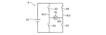
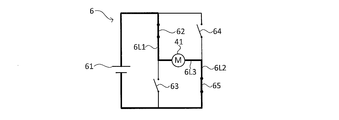
- the electric circuit 6 will be described with reference to FIGS. 16A to 16D.
- the electric circuit 6 is a so-called H-bridge circuit.
- the electric circuit 6 realizes a plurality of states by switching a switch under the control of the control unit 44b. A plurality of states realized by the electric circuit 6 will be described later.
- the electric circuit 6 includes a power supply device 61, a first switch 62, a second switch 63, a third switch 64, a fourth switch 65, and an electric motor 41.
- the power supply device 61 is provided, for example, on the swivel table 12 (see FIG. 1).
- the first switch 62 is, for example, a transistor.
- the first switch 62 is provided on the first line 6L1.
- the first switch 62 is in either an ON state (state shown in FIG. 16B) or an OFF state (state shown in FIGS. 16A, 16C, and 16D) under the control of the control unit 44b (see FIG. 1). Can take the state of.
- the second switch 63 is, for example, a transistor.
- the second switch 63 is provided in series with the first switch 62 on the first line 6L1.
- the second switch 63 is provided on the first line 6L1 on the downstream side in the direction in which the current flows, with respect to the first switch 62.
- the second switch 63 Under the control of the control unit 44b (see FIG. 1), the second switch 63 is in either an ON state (state shown in FIGS. 16C and 16D) or an OFF state (state shown in FIGS. 16A and 16B). Can be taken.
- the third switch 64 is, for example, a transistor.
- the third switch 64 is provided on the second line 6L2.
- the second line 6L2 is in parallel with the first line 6L1.
- the third switch 64 is in either an ON state (state shown in FIG. 16C) or an OFF state (state shown in FIGS. 16A, 16B, and 16D) under the control of the control unit 44b (see FIG. 1). Can take the state of.
- the fourth switch 65 is, for example, a transistor.
- the fourth switch 65 is provided in series with the third switch 64 on the second line 6L2.
- the fourth switch 65 is provided on the second line 6L2 on the downstream side in the direction in which the current flows, with respect to the third switch 64.
- the fourth switch 65 Under the control of the control unit 44b (see FIG. 1), the fourth switch 65 is in either an ON state (state shown in FIGS. 16B and 16D) or an OFF state (state shown in FIGS. 16A and 16C). Can be taken.
- the configuration of the electric motor 41 is as described above.
- the electric motor 41 is provided on the third line 6L3.
- the third line 6L3 connects the portion between the first switch 62 and the second switch 63 in the first line 6L1 and the portion between the third switch 64 and the fourth switch 65 in the second line 6L2. are doing.
- the electric circuit 6 described above can have a non-energized state shown in FIG. 16A, a first driving state shown in FIG. 16B, a second driving state shown in FIG. 16C, and a braking state shown in FIG. 16D.
- the non-energized state of the electric circuit 6 is also referred to as a state in which the connection between the electric motor 41 and the power supply device 61 is disconnected (a state in which power supply from the power supply device 61 to the electric motor 41 is stopped. ).
- the switches 62, 63, 64, and 65 are in the OFF state.
- the first drive state of the electric circuit 6 is a state in which the electric motor 41 and the power supply device 61 are connected (also referred to as a state in which power supply from the power supply device 61 to the electric motor 41 is permitted). Is. In the first drive state of the electric circuit 6, the current flows through the circuit shown by the thick line in FIG. 16B.
- a current in the first direction flows through the electric motor 41.
- the first direction is the direction from the first line 6L1 to the second line 6L2.
- the electric motor 41 rotates in a first direction (the direction of arrow F 2 in Figure 18A ⁇ FIG 18C).
- the first switch 62 and the fourth switch 65 are in the ON state.
- the second switch 63 and the third switch 64 are in the OFF state.
- the first drive state corresponds to an example of the drive state of the electric circuit.
- the second drive state of the electric circuit 6 is a state in which the electric motor 41 and the power supply device 61 are connected (also referred to as a state in which power supply from the power supply device 61 to the electric motor 41 is permitted). Is. In the second drive state of the electric circuit 6, the current flows through the circuit shown by the thick line in FIG. 16C.
- a current in the second direction flows through the electric motor 41.
- the second direction is the direction from the second line 6L2 to the first line 6L1.
- the electric motor 41 rotates in a second direction (direction of the arrow F 1 in FIG. 19A ⁇ FIG 19C) (reversed).
- the second switch 63 and the third switch 64 are in the ON state.
- the first switch 62 and the fourth switch 65 are in the OFF state.
- the second drive state corresponds to an example of the drive state of the electric circuit.
- ⁇ Brake state> In the braking state of the electric circuit 6, as shown in FIG. 16D, the connection between the electric motor 41 and the power supply device 61 is released (power supply from the power supply device 61 to the electric motor 41 is stopped), and the electric circuit 6 is in a braking state.
- This is a state in which the closed circuit 66 (the portion shown by the thick line in FIG. 16D) is formed. That is, the electric circuit 6 has a closed circuit 66 in the braking state.
- the closed circuit 66 is a closed circuit including an electric motor 41, a second switch 63, and a fourth switch 65.
- the first switch 62 and the third switch 64 are in the OFF state. Further, in the braking state of the electric circuit 6, the second switch 63 and the fourth switch 65 are in the ON state. The operation of the electric circuit 6 will be described later.
- FIGS. 18A to 18C are schematic views for explaining the operation of the cylinder connecting mechanism 45.
- FIG. 18A is a schematic view showing an expanded state of the cylinder connecting mechanism 45 and an engaging state of a pair of cylinder connecting pins 454a and 454b and a pair of cylinder pin receiving portions 141a of the tip boom element 141.
- FIG. 18B is a schematic view showing a state in which the cylinder connecting mechanism 45 is in the process of transitioning from the expanded state to the contracted state.
- FIG. 18C is a schematic view showing a reduced state of the cylinder connecting mechanism 45 and a detached state of the pair of cylinder connecting pins 454a and 454b and the pair of cylinder pin receiving portions 141a of the tip boom element 141.
- the cylinder connecting mechanism 45 moves between an expanded state (see FIGS. 8, 12, and 18A) and a reduced state (see FIGS. 13 and 18C) based on the power (that is, rotational motion) of the electric motor 41. State transition.
- FIGS. 18A to 18C the operation of each part when the cylinder connecting mechanism 45 transitions from the expanded state to the contracted state will be described.
- the first missing tooth gear 450 and the second missing tooth gear 460 are schematically shown as an integrated missing tooth gear.
- this integrated missing tooth gear will be described as the first missing tooth gear 450.
- the lock mechanism 47 described later is omitted.
- the position of the first missing tooth gear 450 shown in FIG. 18A is defined as the reference position of the first missing tooth gear 450.
- the control unit 44b switches the electric circuit 6 to the first drive state (see FIG. 16B).
- the power of the electric motor 41 is transmitted to the pair of cylinder connecting pins 454a and 454b in the following first and second paths.
- the first path is the path of the first missing tooth gear 450 ⁇ the first rack bar 451 ⁇ the first gear mechanism 452 ⁇ one of the cylinder connecting pins 454a.
- the second path is the path of the first missing tooth gear 450 ⁇ the first rack bar 451 ⁇ the second gear mechanism 453 ⁇ the other cylinder connecting pin 454b.
- the first toothless gear 450 rotates in the forward rotational direction (direction shown in FIG. 18A by the arrow F 2) ..
- the pair of cylinder connecting pins 454a and 454b are separated from the pair of cylinder pin receiving portions 141a of the tip boom element 141, and are in predetermined positions (for example, the positions shown in FIGS. 2E and 18C). Detects that it has moved to. Then, based on the detection result, the control unit 44b stops the operation of the electric motor 41.
- the state transition from the reduced state to the expanded state of the cylinder connecting mechanism 45 (that is, the state transition from FIG. 18C to FIG. 18A) occurs when the brake mechanism 42 is released in the non-energized state of the electric motor 41. It is automatically performed based on the urging force of the urging mechanism 455. At this time, one cylinder connecting pin 454a and the other cylinder connecting pin 454b move in a direction away from each other.
- the control unit 44b switches the electric circuit 6 to the braking state (see FIG. 16D).
- the electric motor 41 idles based on the urging force of the first urging mechanism 455.
- the electric motor 41 generates electricity based on this idling.
- the current generated by the electric motor 41 passes through the closed circuit 66 and returns to the electric motor 41.
- Lorentz force is generated in the electric motor 41 based on the current returned to the electric motor 41.
- This Lorentz force acts as a braking force on the electric motor 41.
- one cylinder connecting pin 454a and the other cylinder connecting pin 454b stop at the reference position shown in FIG. 18A based on this braking force.
- the detailed operation of the electric circuit 6 will be described later.
- the pair of cylinder connecting pins 454a and 454b are engaged with the pair of cylinder pin receiving portions 141a of the tip boom element 141, and the positions shown in predetermined positions (for example, FIGS. 2A and 18A). ) Is detected. The detection result is used to control the next operation of the actuator 2.
- the boom connecting mechanism 46 corresponds to an example of the operating portion, and is referred to as an expanded state (also referred to as a first state; see FIGS. 8 and 13) and a reduced state (also referred to as a second state) based on the rotation of the electric motor 41.
- the state transitions to and from (see FIG. 12).
- the boom connecting mechanism 46 takes either an engaged state or a disengaged state with respect to the boom connecting pin (for example, a pair of boom connecting pins 144a) in the expanded state.
- the boom connecting mechanism 46 disengages the boom connecting pin from the boom element by transitioning from the expanded state to the contracted state while engaged with the boom connecting pin.
- the boom connecting mechanism 46 engages the boom connecting pin with the boom element by changing the state from the contracted state to the expanded state in the state of being engaged with the boom connecting pin.
- the boom connecting mechanism 46 includes a second missing tooth gear 460, a pair of second rack bars 461a and 461b, a synchronous gear 462 (see FIGS. 18A to 18C), and a second urging mechanism 463.
- Each of the above elements 460, 461a, 461b, and 462 corresponds to an example of a constituent member of the second drive mechanism.
- the pair of boom connecting pins 144a and 144b also correspond to an example of the constituent members of the second drive mechanism.
- the second missing tooth gear 460 (also referred to as a switch gear) has a substantially circular ring plate shape, and has a second tooth portion 460a on a part of the outer peripheral surface in the circumferential direction.
- the second missing tooth gear 460 is externally fitted and fixed on the transmission shaft 432 in the X direction + side of the first missing tooth gear 450, and rotates together with the transmission shaft 432.
- the second missing tooth gear 460 may be a missing tooth gear integrated with the first missing tooth gear 450, for example, as shown in the schematic views shown in FIGS. 14A to 14D.
- the boom coupling mechanism 46 is extended state (FIG. 8, see FIG. 13) when the state transition to the reduced state (see FIG. 12) from the rotating direction (FIG. 8 of the second toothless gear 460 in an arrow F 1 Direction) is the "front side" in the rotation direction of the second missing tooth gear 460.
- the convex portion provided on the frontmost side in the rotation direction of the second missing tooth gear 460 is the positioning tooth 460b (see FIG. 8).
- FIG. 8 is a view of the pin movement module 4 viewed from the + side in the X direction. Therefore, in the case of the present embodiment, the front-rear direction in the rotation direction of the second missing tooth gear 460 is opposite to the front-rear direction in the rotation direction of the first missing tooth gear 450.
- the rotation direction of the second missing tooth gear 460 when the boom connecting mechanism 46 changes from the expanded state to the reduced state is the first missing tooth gear when the cylinder connecting mechanism 45 changes from the expanded state to the reduced state. It is opposite to the direction of rotation of 450.
- ⁇ Second rack bar> The pair of second rack bars 461a and 461b each move in the Y direction (also referred to as the axial direction) with the rotation of the second missing tooth gear 460.
- One second rack bar 461a is located most on the Y direction-side in the expanded state.
- the other second rack bar 461b is located on the + side in the Y direction most in the expanded state.
- one of the second rack bars 461a is located on the + side in the Y direction most in the reduced state.
- the other second rack bar 461b is located most on the Y-direction-side in the reduced state.
- the movement of one second rack bar 461a in the Y direction + side and the movement of the other second rack bar 461b in the Y direction-side are performed, for example, by the stopper surface 48 provided on the housing 40 (FIG. It is regulated by contact with (see 14D).
- the pair of second rack bars 461a and 461b are shaft members long in the Y direction, respectively, and are arranged parallel to each other.
- the pair of second rack bars 461a and 461b are respectively arranged on the + side in the Z direction with respect to the first rack bar 451. Further, the pair of second rack bars 461a and 461b are arranged around the synchronization gear 462 described later in the X direction.
- the longitudinal direction of each of the pair of second rack bars 461a and 461b coincides with the Y direction.
- the pair of second rack bars 461a and 461b have synchronous rack teeth 461e and 461f (see FIGS. 18A to 18C) on the side surfaces facing the X direction, respectively.
- the synchronous rack teeth 461e and 461f are respectively meshed with the synchronous gear 462.
- the pair of second rack bars 461a and 461b each have locking claw portions 461g and 461h (also referred to as locking portions, see FIG. 8) at the tip portions.
- locking claw portions 461g and 461h also referred to as locking portions, see FIG. 8
- the pin side receiving portions 144c see FIG. 8
- the second rack bar 461a has a drive rack tooth portion 461c (see FIG. 8) on the first side surface of the second missing tooth gear 460 (the side surface close to the second missing tooth gear 460).
- the drive rack tooth portion 461c meshes with the second tooth portion 460a of the second missing tooth gear 460.
- the first end surface 461d (Y direction + side end surface) of the drive rack tooth portion 461c comes into contact with the positioning tooth 460b at the second tooth portion 460a of the second missing tooth gear 460. Alternatively, they face each other in the Y direction through a slight gap.
- the positioning tooth 460b presses the first end surface 461d in the Y direction + side. With such pressing, one second rack bar 461a moves to the + side in the Y direction.
- the second urging mechanism 463 automatically returns the boom connecting mechanism 46 to the expanded state when the electric motor 41 is in the non-energized state in the reduced state of the boom connecting mechanism 46.
- the boom connecting mechanism 46 does not automatically return.
- the second urging mechanism 463 may be omitted. In this case, the boom connecting mechanism 46 may transition from the reduced state to the expanded state based on the power of the electric motor 41.
- the second urging mechanism 463 urges the pair of second rack bars 461a and 461b in a direction away from each other.
- the second urging mechanism 463 is composed of a pair of coil springs 463a and 463b (see FIGS. 18A to 17C).
- the pair of coil springs 463a and 463b urge the base end portions of the pair of second rack bars 461a and 461b toward the tip end side, respectively.
- the pair of coil springs 463a and 463b correspond to an example of the second urging member.
- FIGS. 19A to 19C are schematic views for explaining the operation of the boom connecting mechanism 46.
- FIG. 19A is a schematic view showing an expanded state of the boom connecting mechanism 46 and an engaging state of the pair of boom connecting pins 144a and the pair of first boom pin receiving portions 142b of the intermediate boom element 142.
- FIG. 19B is a schematic view showing a state in which the boom connecting mechanism 46 is in the process of transitioning from the expanded state to the contracted state.
- FIG. 19C is a schematic view showing a reduced state of the boom connecting mechanism 46 and a detached state of the pair of boom connecting pins 144a and the pair of first boom pin receiving portions 142b of the intermediate boom element 142.
- the boom connecting mechanism 46 as described above makes a state transition between an expanded state (see FIG. 19A) and a contracted state (see FIG. 19C) based on the power (that is, rotational motion) of the electric motor 41.
- the power that is, rotational motion
- the first missing tooth gear 450 and the second missing tooth gear 460 are schematically shown as an integrated missing tooth gear.
- this integrated missing tooth gear will be described as a second missing tooth gear 460.
- the position of the second missing tooth gear 460 shown in FIG. 19A is defined as the reference position of the second missing tooth gear 460.
- the lock mechanism 47 described later is omitted.
- the control unit 44b switches the electric circuit 6 to the second drive state (see FIG. 16C).
- the power of the electric motor 41 (that is, rotational movement) is transmitted through the path of the second missing tooth gear 460 ⁇ one second rack bar 461a ⁇ synchronous gear 462 ⁇ the other second rack bar 461b.
- the second toothless gear 460 rotates in the forward rotational direction (direction shown in FIGS. 8 and 19A ⁇ FIG 19C by the arrow F 1).
- the synchronous gear 462 rotates according to the movement of one of the second rack bars 461a in the Y direction + side. Then, in response to the rotation of the synchronous gear 462, the other second rack bar 461b moves in the Y direction ⁇ side (left side in FIGS. 19A to 19C).
- the pair of boom connecting pins 144a becomes the pair of first of the intermediate boom elements 142. It separates from the boom pin receiving portion 142b (see FIG. 19C).
- the pair of boom connecting pins 144a is separated from the pair of first boom pin receiving portions 142b of the intermediate boom element 142 and reaches a predetermined position (for example, the position shown in FIGS. 2B and 19C). Detect that it has moved. Then, based on this detection result, the control unit 44b stops the operation of the electric motor 41.
- the closing operation of the boom connecting mechanism 46 (that is, the state transition from FIG. 19C to FIG. 19A) is the urging force of the second urging mechanism 463 when the brake mechanism 42 is released in the non-energized state of the electric motor 41. It is done automatically based on. At the time of this state transition, the pair of boom connecting pins 144a move in a direction away from each other.
- the control unit 44b switches the electric circuit 6 to the braking state (see FIG. 16D). Then, when the electric circuit 6 is switched to the closed circuit 66, the above-mentioned braking force is generated in the electric motor 41. As a result, each of the pair of boom connecting pins 144a stops at the reference position shown in FIG. 19A based on this braking force. The operation of the electric circuit 6 will be described later.
- the pair of boom connecting pins 144a engages with the pair of first boom pin receiving portions 142b of the intermediate boom element 142, and the position information detection device 44 has a predetermined position (for example, the position shown in FIGS. 2A and 19A). Detects that it has moved to. The detection result is used to control the next operation of the actuator 2.
- the boom connecting mechanism 46 when the first tooth portion 450a of the first missing tooth gear 450 meshes with the first rack tooth portion 451a of the first rack bar 451, the boom connecting mechanism 46 The second tooth portion 460a of the second missing tooth gear 460 does not mesh with the drive rack tooth portion 461c of one of the second rack bars 461a.
- the operating portion is the cylinder connecting mechanism 45 and the boom connecting mechanism 46 described above.
- the operating portion is not limited to the cylinder connecting mechanism 45 and the boom connecting mechanism 46.
- the actuating part may be various mechanisms that act on the power of an electrical drive source.
- the actuator 2 has the cylinder connecting pin removed in one boom element (for example, the tip boom element 141) based on the configuration of the boom connecting mechanism 46 and the cylinder connecting mechanism 45.
- the state in which the boom connecting pin is pulled out is not realized at the same time.
- Such a configuration prevents the boom connecting mechanism 46 and the cylinder connecting mechanism 45 from operating at the same time based on the power of the electric motor 41.
- the actuator 2 has an external force other than the electric motor 41 on the cylinder connecting mechanism 45 (for example, the first rack bar 451) or the boom connecting mechanism 46 (for example, the second rack bar 461a).
- Has a lock mechanism 47 that prevents the cylinder connecting mechanism 45 and the boom connecting mechanism 46 from transitioning to each other at the same time when
- Such a lock mechanism 47 prevents the operation of the other coupling mechanism while one of the boom coupling mechanism 46 and the cylinder coupling mechanism 45 is operating.
- the specific structure of the lock mechanism 47 will be described with reference to FIGS. 14A to 14D.
- 14A to 14D are schematic views for explaining the structure of the lock mechanism 47.
- an integrated missing gear 49 (also referred to as a switch gear) in which the first missing gear 450 of the cylinder connecting mechanism 45 and the second missing gear 460 of the boom connecting mechanism 46 are integrally formed. ).
- Such an integrated missing tooth gear 49 has a substantially circular ring plate shape, and has a tooth portion 49a on a part of the outer peripheral surface. The structure of other parts is the same as the structure of the present embodiment described above.
- the lock mechanism 47 has a first convex portion 470, a second convex portion 471, and a cam member 472 (also referred to as a lock side rotating member).
- the first convex portion 470 is integrally provided with the first rack bar 451 of the cylinder connecting mechanism 45. Specifically, the first convex portion 470 is provided at a position adjacent to the first rack tooth portion 451a of the first rack bar 451.
- the second convex portion 471 is integrally provided with one of the second rack bars 461a of the boom connecting mechanism 46. Specifically, the second convex portion 471 is provided at a position adjacent to the drive rack tooth portion 461c of one of the second rack bars 461a.
- the cam member 472 is a plate-shaped member having a substantially crescent shape. Such a cam member 472 has a first cam receiving portion 472a at one end in the circumferential direction. On the other hand, the cam member 472 has a second cam receiving portion 472b at the other end in the circumferential direction.
- the cam member 472 may be externally fitted and fixed at a position shifted in the X direction from the position where the integrated missing tooth gear 49 is externally fixed, for example, on the transmission shaft 432.
- the cam member 472 is externally fitted and fixed between the first missing tooth gear 450 and the second missing tooth gear 460. That is, the cam member 472 and the integrated missing tooth gear 49 are provided coaxially.
- Such a cam member 472 rotates together with the transmission shaft 432. Therefore, the cam member 472 rotates around the central axis of the transmission shaft 432 together with the integrated missing tooth gear 49.
- the cam member 472 may be integrated with the integrated missing tooth gear 49. Further, in the case of the present embodiment, the cam member 472 may be integrated with at least one of the first missing gear 450 and the second missing gear 460.
- the tooth portion 49a of the integrated missing tooth gear 49 (also the second tooth portion 460a of the second missing tooth gear 460) is one of the second rack bars.
- the first cam receiving portion 472a of the cam member 472 is located on the + side in the Y direction with respect to the first convex portion 470 in a state of being meshed with the drive rack tooth portion 461c of the 461a.
- the tooth portion 49a of the integrated missing gear 49 does not mesh with the first rack tooth portion 451a of the first rack bar 451.
- the first cam receiving portion 472a and the first convex portion 470 face each other with a slight gap in the Y direction (see FIG. 15A).
- the first rack bar 451 Y-direction + side of the external force force indicated by the arrow F a in FIG. 15A
- the movement of the Y-direction + side of the first rack bar 451 is prevented To.
- the tooth portion 49a of the integrated missing tooth gear 49 (the first tooth portion 450a of the first missing tooth gear 450 in the cylinder connecting mechanism 45) is the first of the first rack bar 451.
- the second cam receiving portion 472b of the cam member 472 is located on the + side in the Y direction with respect to the second convex portion 471.
- the electric circuit 6 may take any one of the above-mentioned non-energized state, first drive state, second drive state, and braking state.
- First drive state Specifically, in the electric circuit 6, when the cylinder connecting mechanism 45 (also referred to as the first connecting mechanism) changes from the expanded state to the contracted state (hereinafter, also referred to as “pulling operation of the cylinder connecting mechanism 45”). In the first drive state (see FIG. 16B). In other words, the control unit 44b switches the electric circuit 6 to the first drive state in the pulling operation of the cylinder connecting mechanism 45.
- the electric circuit 6 is used when the boom connecting mechanism 46 (also referred to as a second connecting mechanism) undergoes a state transition from an expanded state to a contracted state (hereinafter, also referred to as “pulling operation of the boom connecting mechanism 46”). It is in the second drive state (see FIG. 16C). In other words, the control unit 44b switches the electric circuit 6 to the second drive state in the pulling operation of the boom connecting mechanism 46.
- the electric motor 41 idles based on the urging force of the second urging mechanism 463.
- the electric motor 41 generates electricity based on this idling.
- the current generated by the electric motor 41 passes through the closed circuit 66 and returns to the electric motor 41.
- Lorentz force is generated in the electric motor 41 based on the current returned to the electric motor 41.
- This Lorentz force acts as a braking force on the electric motor 41.
- the current is converted into thermal energy by a resistor (not shown) provided in the closed circuit 66.
- the braking force as described above is adjusted according to the resistance value of the closed circuit 66. As an example, the resistance value may be adjusted manually by the operator.
- the braking force as described above contributes to the prevention of overrun of the second missing tooth gear 460 (see FIGS. 19A to 19C) in the engaging operation of the boom connecting mechanism 46. The reason for this will be described with reference to FIGS. 19A to 19C.
- the second missing tooth gear 460 idles based on the rotation.
- the electric motor 41 generates electricity based on this idling.
- the current generated by the electric motor 41 passes through the closed circuit 66 and returns to the electric motor 41.
- Lorentz force is generated in the electric motor 41 based on the current returned to the electric motor 41.
- This Lorentz force acts as a braking force on the electric motor 41.
- the current is converted into thermal energy by a resistor (not shown) provided in the closed circuit 66.
- a braking force also acts on the second missing tooth gear 460 as a resistance force against the rotation of the second missing tooth gear 460.
- the second missing tooth gear 460 stops at the reference position shown in FIG. 19A.
- the force in the pulling operation direction does not act on the cylinder connecting mechanism 45.
- the force in the pulling operation direction means a force that causes the cylinder connecting mechanism 45 to transition from the state shown in FIG. 18A to the state shown in FIG. 18B.
- the idling of the electric motor 41 is also stopped, so that the above-mentioned braking force is not generated. Therefore, the above-mentioned braking force does not act on the second missing tooth gear 460 in the stopped state.
- the braking force described above is a force that stops the cylinder connecting pin 454a, 454b and the boom connecting pin 144a at positions other than the first end and the second end in the stroke of the cylinder connecting pin 454a, 454b and the boom connecting pin 144a. Does not have.
- the first end of the stroke corresponds to a position (position shown in FIGS. 18A and 19A) corresponding to the inserted state of the cylinder connecting pin 454a, 454b and the boom connecting pin 144a.
- the second end of the stroke corresponds to a position (position shown in FIGS. 18C and 19C) corresponding to the removed state of the cylinder connecting pin 454a, 454b and the boom connecting pin 144a.
- the cylinder connecting pins 454a and 454b and the boom connecting pin 144a do not stop in the middle of the operation (that is, at positions other than both ends in the stroke). If the cylinder connecting pin 454a, 454b and the boom connecting pin 144a stop in the middle of operation, it may cause a failure. According to the present embodiment, it is possible to prevent the cylinder connecting pin 454a, 454b and the boom connecting pin 144a from stopping at a position that causes such a failure, so that the cylinder connecting mechanism 45, the boom connecting mechanism 46, and the boom connecting mechanism 46, by extension, , The failure of the mobile crane 1 can be suppressed.
- the electric motor 41 idles based on the urging force of the first urging mechanism 455.
- the electric motor 41 generates electricity based on this idling.
- the current generated by the electric motor 41 passes through the closed circuit 66 and returns to the electric motor 41.
- Lorentz force is generated in the electric motor 41 based on the current returned to the electric motor 41. This Lorentz force acts as a braking force on the electric motor 41.
- Such braking force contributes to the prevention of overrun of the first missing tooth gear 450 in the engaging operation of the cylinder connecting mechanism 45.
- the reason for this is the same as in the case of the boom connecting mechanism 46 described above, and thus description thereof will be omitted.
- FIG. 17 is a timing chart of the telescopic boom 14 when the tip boom element 141 is extended.
- the actuator 2 switches the rotation direction of one electric motor 41 and distributes the driving force of the electric motor 41 to the cylinder connecting mechanism 45 and the boom connecting mechanism 46 (that is, the first missing switch gear).
- the tooth gear 450 and the second missing tooth gear 460 With the tooth gear 450 and the second missing tooth gear 460), the pulling operation of the cylinder connecting pin 454a and 454b and the pulling operation of the boom connecting pin 144a are selectively realized.
- the contraction operation of the tip boom element 141 is the reverse of the procedure of the expansion / contraction operation described below.
- the ON / OFF switching of the electric motor 41 and the ON / OFF switching of the brake mechanism 42 are controlled by the control unit based on the output of the position information detection device 44 described above.
- FIG. 2A shows the contracted state of the telescopic boom 14.
- the tip boom element 141 is connected to the intermediate boom element 142 via the boom connecting pin 144a. Therefore, the tip boom element 141 cannot move in the longitudinal direction (left-right direction of FIGS. 2A to 2E) with respect to the intermediate boom element 142.
- the tip portions of the cylinder connecting pins 454a and 454b engage with the pair of cylinder pin receiving portions 141a of the tip boom element 141. That is, the tip boom element 141 and the cylinder member 32 are in a connected state.
- the electric motor 41 is rotated in the normal direction (rotated in the first direction which is the clockwise direction when viewed from the tip side of the output shaft), and the pair is formed by the boom connecting mechanism 46 of the actuator 2.
- the boom connecting pin 144a is moved in a direction away from the pair of first boom pin receiving portions 142b of the intermediate boom element 142.
- the boom connecting mechanism 46 makes a state transition from the expanded state to the contracted state.
- the pair of boom connecting pins 144a and the pair of first boom pin receiving portions 142b of the intermediate boom element 142 are disengaged (see FIG. 2B).
- the brake mechanism 42 is turned on and the electric motor 41 is turned off.
- the timing of turning off the electric motor 41 and the timing of turning on the brake mechanism 42 are appropriately controlled by the control unit. For example, although not shown, the electric motor 41 is turned off after the brake mechanism 42 is turned on.
- the tip boom element 141 moves in the extension direction (see FIG. 2C). At this time, as for the state of each part, the state of T2 in FIG. 17 is maintained until T3.
- the brake mechanism 42 is released. Then, based on the urging force of the second urging mechanism 463, the boom connecting mechanism 46 moves the pair of boom connecting pins 144a in the direction of engaging the pair of second boom pin receiving portions 142c of the intermediate boom element 142. At this time, the boom connecting mechanism 46 makes a state transition (that is, automatic return) from the contracted state to the expanded state. That is, the boom connecting mechanism 46 is turned on.
- a state transition that is, automatic return
- the electric circuit 6 described above is in a braking state (see FIG. 16D).
- the electric circuit 6 is switched to the closed circuit 66, so that the braking force as described above acts on the electric motor 41.
- Each of the pair of boom connecting pins 144a stops at the reference position of the boom connecting pins 144a shown in FIG. 19A based on this braking force.
- the pair of boom connecting pins 144a engages with the pair of second boom pin receiving portions 142c of the intermediate boom element 142.
- the electric motor 41 is reversed (rotated in the second direction which is the counterclockwise direction when viewed from the tip side of the output shaft), and the cylinder connecting mechanism 45 causes a pair of cylinder connecting pins.
- the 454a and 454b are moved in a direction away from the pair of cylinder pin receiving portions 141a of the tip boom element 141.
- the cylinder connecting mechanism 45 makes a state transition from the expanded state to the reduced state.
- the electric circuit 6 described above is in a braking state (see FIG. 16D). Then, when the electric circuit 6 is switched to the closed circuit 66, the above-mentioned braking force is generated in the electric motor 41. When this braking force acts on the electric motor 41, the pair of cylinder connecting pins 454a and 454b each stop at the reference position shown in FIG. 18A based on this braking force. In this way, since the overrun of the first missing tooth gear 450 (see FIG. 18A) of the cylinder connecting mechanism 45 is prevented, a force acts on the boom connecting mechanism 46 in the direction of transitioning from the expanded state to the contracted state. There is no such thing.
- the cylinder connecting mechanism 45 and the boom connecting mechanism 46 are electric, it is not necessary to provide a hydraulic circuit in the internal space of the telescopic boom 14 as in the conventional structure. Therefore, the space used by the hydraulic circuit can be effectively utilized to improve the degree of freedom in designing the internal space of the telescopic boom 14.
- the positions of the cylinder connecting pins 454a and 454b and the boom connecting pins 144a and 144b are detected by the above-mentioned position information detecting device 44. Therefore, in the present embodiment, the proximity sensor for detecting the positions of the cylinder connecting pins 454a and 454b and the boom connecting pins 144a and 144b becomes unnecessary. Such a proximity sensor is provided at a position where, for example, the cylinder connecting pin 454a, 454b and the boom connecting pin 144a, 144b can detect the inserted state and the disconnected state, respectively.
- the cylinder connecting pins 454a and 454b and the boom connecting pins 144a and 144b are respectively provided by the position information detecting device 44 (that is, one detector) including one detecting unit 44a as described above. The position of can be detected.
- the working machine is Actuators that expand and contract the telescopic boom, and An electrical drive source provided in the actuator and driven based on the power supply from the power supply, It is provided with a working unit that operates based on the power of an electric drive source as a basic configuration.
- the working machine is additionally used. Braking that allows power supply from the power source to the electric drive source and drives the electric drive source, and stops power supply from the power source to the electric drive source to generate braking force applied to the electric drive source.
- An electric circuit that can switch between states and A control unit that controls switching between a driving state and a braking state may be provided.
- the boom may additionally have a first boom element and a second boom element that are stretchably overlapped with each other.
- the operating portion when carrying out the present invention, additionally A first coupling mechanism that operates based on the power of an electrical drive source and switches between a connected state and a non-connected state of the first boom element and the actuator. It may be provided with a second connecting mechanism that operates based on the power of an electric drive source and switches between a connected state and a non-connected state of the first boom element and the second boom element.
- the working machine according to an example of the reference example of the present invention may include an arbitrary configuration selected from the configuration of the working machine described in the above-described embodiment in addition to the above-mentioned basic configuration.
- the working machine according to such a reference example is not limited to a crane, and may be various working machines provided with a telescopic boom.
- the crane according to the present invention is not limited to a rough terrain crane, and may be, for example, various mobile cranes such as an all-terrain crane, a truck crane, or a loaded truck crane (also referred to as a cargo crane). Further, the crane according to the present invention is not limited to a mobile crane, and may be another crane provided with a telescopic boom.
Abstract
Cet engin de chantier comprend : un actionneur qui étend et rétracte une flèche télescopique ; une source d'entraînement électrique qui est disposée sur l'actionneur et entraînée par l'énergie fournie par un bloc d'alimentation ; une unité de fonctionnement qui fonctionne avec l'énergie provenant de la source d'entraînement électrique ; un circuit électrique capable de commuter entre un état d'entraînement dans lequel l'énergie peut être fournie à la source d'entraînement électrique en provenance du bloc d'alimentation pour entraîner la source d'entraînement électrique, et un état de freinage dans lequel l'alimentation en énergie du bloc d'alimentation à la source d'entraînement électrique est arrêtée et une force de freinage à appliquer à la source d'entraînement électrique est générée ; et une unité de commande qui commande la commutation entre l'état d'entraînement et l'état de freinage.
Priority Applications (4)
| Application Number | Priority Date | Filing Date | Title |
|---|---|---|---|
| JP2021512316A JP7424370B2 (ja) | 2019-04-04 | 2020-04-03 | 作業機 |
| CN202080025470.7A CN113677615B (zh) | 2019-04-04 | 2020-04-03 | 作业机 |
| US17/600,287 US20220169484A1 (en) | 2019-04-04 | 2020-04-03 | Work machine |
| EP20782937.5A EP3950565A4 (fr) | 2019-04-04 | 2020-04-03 | Engin de chantier |
Applications Claiming Priority (2)
| Application Number | Priority Date | Filing Date | Title |
|---|---|---|---|
| JP2019072143 | 2019-04-04 | ||
| JP2019-072143 | 2019-04-04 |
Publications (1)
| Publication Number | Publication Date |
|---|---|
| WO2020204153A1 true WO2020204153A1 (fr) | 2020-10-08 |
Family
ID=72668140
Family Applications (1)
| Application Number | Title | Priority Date | Filing Date |
|---|---|---|---|
| PCT/JP2020/015267 WO2020204153A1 (fr) | 2019-04-04 | 2020-04-03 | Engin de chantier |
Country Status (4)
| Country | Link |
|---|---|
| US (1) | US20220169484A1 (fr) |
| EP (1) | EP3950565A4 (fr) |
| JP (1) | JP7424370B2 (fr) |
| WO (1) | WO2020204153A1 (fr) |
Cited By (6)
| Publication number | Priority date | Publication date | Assignee | Title |
|---|---|---|---|---|
| CN113409516A (zh) * | 2021-02-05 | 2021-09-17 | 苏州优智达机器人有限公司 | 一种货柜的传输机构、货架及货柜 |
| US20220169485A1 (en) * | 2019-04-04 | 2022-06-02 | Tadano Ltd. | Work machine |
| WO2023006583A1 (fr) * | 2021-07-28 | 2023-02-02 | Liebherr-Components Kirchdorf GmbH | Tête de verrouillage |
| WO2023058650A1 (fr) * | 2021-10-06 | 2023-04-13 | 株式会社タダノ | Engin de chantier |
| WO2023074688A1 (fr) * | 2021-10-28 | 2023-05-04 | 株式会社タダノ | Machine de travail |
| WO2023243641A1 (fr) * | 2022-06-17 | 2023-12-21 | 株式会社タダノ | Engin de chantier |
Citations (5)
| Publication number | Priority date | Publication date | Assignee | Title |
|---|---|---|---|---|
| JP2012096928A (ja) | 2011-12-12 | 2012-05-24 | Kato Works Co Ltd | クレーンのブーム伸縮装置 |
| JP2016155654A (ja) * | 2015-02-24 | 2016-09-01 | 株式会社タダノ | 伸縮ブームの伸縮装置 |
| JP2017154875A (ja) * | 2016-03-03 | 2017-09-07 | 株式会社タダノ | 伸縮機構 |
| JP2017159973A (ja) * | 2016-03-07 | 2017-09-14 | 株式会社タダノ | ブーム伸縮装置 |
| JP2019072143A (ja) | 2017-10-13 | 2019-05-16 | 株式会社三洋物産 | 遊技機 |
Family Cites Families (13)
| Publication number | Priority date | Publication date | Assignee | Title |
|---|---|---|---|---|
| JPS5233378B2 (fr) * | 1972-01-31 | 1977-08-27 | ||
| US4498556A (en) * | 1982-09-11 | 1985-02-12 | Access Engineering Ltd. | Vertically movable, road towable work platform |
| US4688690A (en) * | 1986-03-07 | 1987-08-25 | Harnischfeger Corporation | Method and apparatus for extending fly section of crane boom |
| US5598072A (en) * | 1995-04-04 | 1997-01-28 | General Electric Company | Regenerative braking circuit utilizing separately excited motor |
| FR2797862B1 (fr) * | 1999-09-01 | 2001-11-16 | Ppm | Procede de telescopage d'une fleche de grue, dispositif pour sa mise en oeuvre et fleche de grue en faisant application |
| DE10048224B4 (de) * | 2000-09-21 | 2005-06-02 | Terex-Demag Gmbh & Co. Kg | Verriegelungseinheit für einen Teleskopausleger eines Krans |
| US6490479B2 (en) | 2000-12-28 | 2002-12-03 | Ge Medical Systems Information Technologies, Inc. | Atrial fibrillation detection method and apparatus |
| CN101723262B (zh) * | 2008-10-15 | 2011-09-14 | 徐州重型机械有限公司 | 伸缩臂插销机构控制系统 |
| JP5684996B2 (ja) | 2010-03-30 | 2015-03-18 | 株式会社タダノ | ブーム |
| DE202013010381U1 (de) * | 2013-11-11 | 2013-11-26 | Terex Cranes Germany Gmbh | Antrieb einer Schiebekulisse eines Verriegelungssystems eines Teleskopiersystems eines Kranauslegers |
| JP6266434B2 (ja) * | 2014-05-19 | 2018-01-24 | 株式会社タダノ | 作業機械のブーム自動伸縮装置 |
| CN106856390A (zh) * | 2015-12-09 | 2017-06-16 | 国家电网公司 | 电动绞磨机直流电机正、反转及刹车电路 |
| CN105417410A (zh) * | 2015-12-31 | 2016-03-23 | 徐州重型机械有限公司 | 带有锁定机构的伸缩臂结构及起重机 |
-
2020
- 2020-04-03 EP EP20782937.5A patent/EP3950565A4/fr active Pending
- 2020-04-03 US US17/600,287 patent/US20220169484A1/en active Pending
- 2020-04-03 WO PCT/JP2020/015267 patent/WO2020204153A1/fr unknown
- 2020-04-03 JP JP2021512316A patent/JP7424370B2/ja active Active
Patent Citations (5)
| Publication number | Priority date | Publication date | Assignee | Title |
|---|---|---|---|---|
| JP2012096928A (ja) | 2011-12-12 | 2012-05-24 | Kato Works Co Ltd | クレーンのブーム伸縮装置 |
| JP2016155654A (ja) * | 2015-02-24 | 2016-09-01 | 株式会社タダノ | 伸縮ブームの伸縮装置 |
| JP2017154875A (ja) * | 2016-03-03 | 2017-09-07 | 株式会社タダノ | 伸縮機構 |
| JP2017159973A (ja) * | 2016-03-07 | 2017-09-14 | 株式会社タダノ | ブーム伸縮装置 |
| JP2019072143A (ja) | 2017-10-13 | 2019-05-16 | 株式会社三洋物産 | 遊技機 |
Non-Patent Citations (1)
| Title |
|---|
| See also references of EP3950565A4 |
Cited By (7)
| Publication number | Priority date | Publication date | Assignee | Title |
|---|---|---|---|---|
| US20220169485A1 (en) * | 2019-04-04 | 2022-06-02 | Tadano Ltd. | Work machine |
| US11958726B2 (en) * | 2019-04-04 | 2024-04-16 | Tadano Ltd. | Work machine |
| CN113409516A (zh) * | 2021-02-05 | 2021-09-17 | 苏州优智达机器人有限公司 | 一种货柜的传输机构、货架及货柜 |
| WO2023006583A1 (fr) * | 2021-07-28 | 2023-02-02 | Liebherr-Components Kirchdorf GmbH | Tête de verrouillage |
| WO2023058650A1 (fr) * | 2021-10-06 | 2023-04-13 | 株式会社タダノ | Engin de chantier |
| WO2023074688A1 (fr) * | 2021-10-28 | 2023-05-04 | 株式会社タダノ | Machine de travail |
| WO2023243641A1 (fr) * | 2022-06-17 | 2023-12-21 | 株式会社タダノ | Engin de chantier |
Also Published As
| Publication number | Publication date |
|---|---|
| EP3950565A1 (fr) | 2022-02-09 |
| JPWO2020204153A1 (fr) | 2020-10-08 |
| EP3950565A4 (fr) | 2023-01-04 |
| JP7424370B2 (ja) | 2024-01-30 |
| US20220169484A1 (en) | 2022-06-02 |
Similar Documents
| Publication | Publication Date | Title |
|---|---|---|
| WO2020204153A1 (fr) | Engin de chantier | |
| US11629035B2 (en) | Crane | |
| US11542131B2 (en) | Crane | |
| US11926512B2 (en) | Work machine | |
| CN113677615B (zh) | 作业机 | |
| WO2023058650A1 (fr) | Engin de chantier | |
| WO2023074696A1 (fr) | Engin de chantier | |
| US20230356986A1 (en) | Work vehicle | |
| US20220267120A1 (en) | Work machine | |
| WO2023074700A1 (fr) | Machine de travail | |
| JP2023067724A (ja) | 作業機 |
Legal Events
| Date | Code | Title | Description |
|---|---|---|---|
| 121 | Ep: the epo has been informed by wipo that ep was designated in this application |
Ref document number: 20782937 Country of ref document: EP Kind code of ref document: A1 |
|
| ENP | Entry into the national phase |
Ref document number: 2021512316 Country of ref document: JP Kind code of ref document: A |
|
| NENP | Non-entry into the national phase |
Ref country code: DE |
|
| ENP | Entry into the national phase |
Ref document number: 2020782937 Country of ref document: EP Effective date: 20211104 |