WO2020204153A1 - Work machine - Google Patents
Work machine Download PDFInfo
- Publication number
- WO2020204153A1 WO2020204153A1 PCT/JP2020/015267 JP2020015267W WO2020204153A1 WO 2020204153 A1 WO2020204153 A1 WO 2020204153A1 JP 2020015267 W JP2020015267 W JP 2020015267W WO 2020204153 A1 WO2020204153 A1 WO 2020204153A1
- Authority
- WO
- WIPO (PCT)
- Prior art keywords
- state
- boom
- cylinder
- pair
- electric motor
- Prior art date
Links
- 230000007246 mechanism Effects 0.000 claims description 313
- 230000008878 coupling Effects 0.000 claims description 8
- 238000010168 coupling process Methods 0.000 claims description 8
- 238000005859 coupling reaction Methods 0.000 claims description 8
- 230000007704 transition Effects 0.000 description 49
- 238000001514 detection method Methods 0.000 description 46
- 230000005540 biological transmission Effects 0.000 description 36
- 230000033001 locomotion Effects 0.000 description 24
- 230000008602 contraction Effects 0.000 description 22
- 239000003638 chemical reducing agent Substances 0.000 description 19
- 238000010586 diagram Methods 0.000 description 14
- 230000001360 synchronised effect Effects 0.000 description 11
- 238000000034 method Methods 0.000 description 5
- 230000002093 peripheral effect Effects 0.000 description 5
- 239000000470 constituent Substances 0.000 description 4
- 230000005611 electricity Effects 0.000 description 4
- 210000000078 claw Anatomy 0.000 description 3
- 230000002265 prevention Effects 0.000 description 3
- 230000006872 improvement Effects 0.000 description 2
- 230000008569 process Effects 0.000 description 2
- 238000011000 absolute method Methods 0.000 description 1
- 230000009471 action Effects 0.000 description 1
- 230000000694 effects Effects 0.000 description 1
- 238000005259 measurement Methods 0.000 description 1
- 230000001105 regulatory effect Effects 0.000 description 1
- 230000004044 response Effects 0.000 description 1
- 238000011144 upstream manufacturing Methods 0.000 description 1
Images


Classifications
-
- B—PERFORMING OPERATIONS; TRANSPORTING
- B66—HOISTING; LIFTING; HAULING
- B66C—CRANES; LOAD-ENGAGING ELEMENTS OR DEVICES FOR CRANES, CAPSTANS, WINCHES, OR TACKLES
- B66C23/00—Cranes comprising essentially a beam, boom, or triangular structure acting as a cantilever and mounted for translatory of swinging movements in vertical or horizontal planes or a combination of such movements, e.g. jib-cranes, derricks, tower cranes
- B66C23/62—Constructional features or details
- B66C23/64—Jibs
- B66C23/70—Jibs constructed of sections adapted to be assembled to form jibs or various lengths
- B66C23/701—Jibs constructed of sections adapted to be assembled to form jibs or various lengths telescopic
- B66C23/706—Jibs constructed of sections adapted to be assembled to form jibs or various lengths telescopic telescoped by other means
-
- B—PERFORMING OPERATIONS; TRANSPORTING
- B66—HOISTING; LIFTING; HAULING
- B66C—CRANES; LOAD-ENGAGING ELEMENTS OR DEVICES FOR CRANES, CAPSTANS, WINCHES, OR TACKLES
- B66C23/00—Cranes comprising essentially a beam, boom, or triangular structure acting as a cantilever and mounted for translatory of swinging movements in vertical or horizontal planes or a combination of such movements, e.g. jib-cranes, derricks, tower cranes
- B66C23/62—Constructional features or details
- B66C23/64—Jibs
- B66C23/70—Jibs constructed of sections adapted to be assembled to form jibs or various lengths
- B66C23/701—Jibs constructed of sections adapted to be assembled to form jibs or various lengths telescopic
- B66C23/705—Jibs constructed of sections adapted to be assembled to form jibs or various lengths telescopic telescoped by hydraulic jacks
-
- B—PERFORMING OPERATIONS; TRANSPORTING
- B66—HOISTING; LIFTING; HAULING
- B66C—CRANES; LOAD-ENGAGING ELEMENTS OR DEVICES FOR CRANES, CAPSTANS, WINCHES, OR TACKLES
- B66C23/00—Cranes comprising essentially a beam, boom, or triangular structure acting as a cantilever and mounted for translatory of swinging movements in vertical or horizontal planes or a combination of such movements, e.g. jib-cranes, derricks, tower cranes
- B66C23/62—Constructional features or details
- B66C23/64—Jibs
- B66C23/70—Jibs constructed of sections adapted to be assembled to form jibs or various lengths
- B66C23/701—Jibs constructed of sections adapted to be assembled to form jibs or various lengths telescopic
- B66C23/708—Jibs constructed of sections adapted to be assembled to form jibs or various lengths telescopic locking devices for telescopic jibs
-
- E—FIXED CONSTRUCTIONS
- E02—HYDRAULIC ENGINEERING; FOUNDATIONS; SOIL SHIFTING
- E02F—DREDGING; SOIL-SHIFTING
- E02F3/00—Dredgers; Soil-shifting machines
- E02F3/04—Dredgers; Soil-shifting machines mechanically-driven
- E02F3/28—Dredgers; Soil-shifting machines mechanically-driven with digging tools mounted on a dipper- or bucket-arm, i.e. there is either one arm or a pair of arms, e.g. dippers, buckets
- E02F3/283—Dredgers; Soil-shifting machines mechanically-driven with digging tools mounted on a dipper- or bucket-arm, i.e. there is either one arm or a pair of arms, e.g. dippers, buckets with a single arm pivoted directly on the chassis
- E02F3/286—Dredgers; Soil-shifting machines mechanically-driven with digging tools mounted on a dipper- or bucket-arm, i.e. there is either one arm or a pair of arms, e.g. dippers, buckets with a single arm pivoted directly on the chassis telescopic or slidable
Definitions
- the present invention relates to a working machine provided with a telescopic boom.
- Patent Document 1 discloses a telescopic boom in which a plurality of boom elements are nested (also referred to as a telescopic shape), and a mobile crane including a hydraulic telescopic cylinder for extending the telescopic boom. There is.
- the telescopic boom has a boom connecting pin that connects adjacent and overlapping boom elements.
- the boom element hereinafter referred to as a movable boom element
- the boom connecting pin can move in the longitudinal direction (also referred to as expansion / contraction direction) with respect to other boom elements.
- the telescopic cylinder has a rod member and a cylinder member.
- a telescopic cylinder connects a cylinder member to the movable boom element via a cylinder connecting pin.
- the crane as described above includes a hydraulic actuator for moving the boom connecting pin, a hydraulic actuator for moving the cylinder connecting pin, and a hydraulic circuit for supplying pressure oil to each of these actuators.
- a hydraulic circuit is provided, for example, around a telescopic boom. This can reduce the degree of freedom in design around the telescopic boom.
- An object of the present invention is to provide a working machine capable of improving the degree of freedom in design around the telescopic boom.
- the working machine is Actuators that expand and contract the telescopic boom, and An electrical drive source provided in the actuator and driven based on the power supply from the power supply, An actuating part that operates based on the power of an electrical drive source, Braking that allows power supply from the power source to the electric drive source and drives the electric drive source, and stops power supply from the power source to the electric drive source to generate braking force applied to the electric drive source.
- An electric circuit that can switch between states and It is provided with a control unit that controls switching between a driving state and a braking state.
- the degree of freedom in design around the telescopic boom can be improved.
- FIG. 1 is a schematic view of a mobile crane according to an embodiment.
- 2A to 2E are schematic views for explaining the structure and expansion / contraction operation of the telescopic boom.
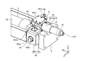
- FIG. 3A is a perspective view of the actuator.
- FIG. 3B is an enlarged view of part A of FIG. 3A.
- FIG. 4 is a partial plan view of the actuator.
- FIG. 5 is a partial side view of the actuator.
- Figure 6 is a A 1 arrow view of FIG.
- FIG. 7 is a perspective view of the pin moving module in a state where the boom connecting pin is held.
- FIG. 8 is a front view of the pin moving module in the expanded state and the state in which the boom connecting pin is held.
- Figure 9 is a A 2 arrow view of FIG.
- FIG. 10 is a A 3 arrow view of FIG. Figure 11 is a A 4 arrow view of FIG.
- FIG. 12 is a front view of the pin moving module in which the boom connecting mechanism is in the reduced state and the cylinder connecting mechanism is in the expanded state.
- FIG. 13 is a front view of the pin moving module in which the boom connecting mechanism is in the expanded state and the cylinder connecting mechanism is in the reduced state.
- FIG. 14A is a schematic diagram for explaining the operation of the lock mechanism.
- FIG. 14B is a schematic diagram for explaining the operation of the lock mechanism.
- FIG. 14C is a schematic diagram for explaining the operation of the lock mechanism.
- FIG. 14D is a schematic diagram for explaining the operation of the lock mechanism.
- FIG. 15A is a schematic diagram for explaining the operation of the locking mechanism.
- FIG. 15B is a schematic diagram for explaining the operation of the locking mechanism.
- FIG. 16A is a circuit diagram of an electric circuit in a non-energized state.
- FIG. 16B is a circuit diagram of an electric circuit in the first drive state.
- FIG. 16C is a circuit diagram of an electric circuit in the second drive state.
- FIG. 16D is a circuit diagram of an electric circuit in a braking state.
- FIG. 17 is a timing chart during the extension operation of the telescopic boom.
- FIG. 18A is a schematic view for explaining the operation of the cylinder connecting mechanism.
- FIG. 18B is a schematic diagram for explaining the operation of the cylinder connecting mechanism.
- FIG. 18C is a schematic diagram for explaining the operation of the cylinder connecting mechanism.
- FIG. 19A is a schematic view for explaining the operation of the boom connecting mechanism.
- FIG. 19B is a schematic diagram for explaining the operation of the boom connecting mechanism.
- FIG. 19C is a schematic diagram for explaining the operation of the boom
- FIG. 1 is a schematic view of a mobile crane 1 (rough terrain crane in the case of illustration) according to the present embodiment.
- the mobile crane 1 corresponds to an example of a working machine.
- mobile cranes examples include all-terrain cranes, truck cranes, and loaded truck cranes (also referred to as cargo cranes).
- the work machine according to the present invention is not limited to the mobile crane, and can be applied to other work vehicles (for example, cranes, aerial work platforms) having a telescopic boom.
- the mobile crane 1 includes a traveling body 10, an outrigger 11, a swivel base 12, a telescopic boom 14, an actuator 2 (omitted in FIG. 1), and an electric circuit 6 (FIG. 16A). (See FIG. 16D), an undulating cylinder 15, a wire 16, and a hook 17.
- the traveling body 10 has a plurality of wheels 101. Outriggers 11 are provided at the four corners of the traveling body 10.
- the swivel base 12 is provided on the upper portion of the traveling body 10 so as to be swivelable.
- the base end of the telescopic boom 14 is fixed to the swivel base 12.
- the actuator 2 expands and contracts the telescopic boom 14.
- the undulating cylinder 15 undulates the telescopic boom 14.
- the wire 16 hangs down from the tip of the telescopic boom 14.
- the hook 17 is provided at the tip of the wire 16.
- FIGS. 1 and 2A to 2E are schematic views for explaining the structure and expansion / contraction operation of the telescopic boom 14.
- FIG. 1 shows a telescopic boom 14 in an extended state.
- FIG. 2A shows a telescopic boom 14 in a contracted state.
- FIG. 2E shows a telescopic boom 14 in which only the tip boom element 141, which will be described later, is extended.
- the telescopic boom 14 is composed of a plurality of boom elements. Each of the boom elements is tubular. The boom elements are telescopically combined with each other. Specifically, in the contracted state, the plurality of boom elements are the tip boom element 141, the intermediate boom element 142, and the proximal boom element 143 in order from the inside.
- the tip boom element 141 and the intermediate boom element 142 correspond to an example of the first boom element that can move in the expansion / contraction direction.
- the tip boom element 141 moves in the expansion / contraction direction with respect to the intermediate boom element 142
- the tip boom element 141 corresponds to an example of the first boom element
- the intermediate boom element 142 corresponds to an example of the second boom element.
- the intermediate boom element 142 moves in the expansion / contraction direction with respect to the proximal boom element 143
- the intermediate boom element 142 corresponds to an example of the first boom element
- the proximal boom element 143 corresponds to the second boom.
- the base end boom element 143 is restricted from moving in the expansion / contraction direction.
- the intermediate boom element 142 is arranged between the proximal end boom element 143 on the most proximal end side and the distal boom element 141 on the most distal end side.
- the number of intermediate boom elements may be plural.
- the structure of the telescopic boom 14 is almost the same as the structure of the conventionally known telescopic boom, but for convenience of explanation regarding the structure and operation of the actuator 2 described later, the tip boom element 141 and the intermediate boom are described below. The structure of the element 142 will be described.
- the tip boom element 141 has a tubular shape as shown in FIGS. 2A to 2E.
- the tip boom element 141 has an internal space that can accommodate the actuator 2.
- the tip boom element 141 has a pair of cylinder pin receiving portions 141a and a pair of boom pin receiving portions 141b at the base end portion.
- the pair of cylinder pin receiving portions 141a are provided coaxially with each other at the base end portion of the tip boom element 141.
- Each of the pair of cylinder pin receiving portions 141a can be engaged with and detached from the pair of cylinder connecting pins 454a and 454b (also referred to as the first connecting member) provided in the cylinder member 32 of the telescopic cylinder 3. That is, either the pair of cylinder pin receiving portions 141a is engaged with the pair of cylinder connecting pins 454a and 454b, or the pair of cylinder pin receiving portions 141a is disengaged with the pair of cylinder connecting pins 454a and 454b. It can take one state.
- the cylinder connecting pins 454a and 454b move in their own axial direction based on the operation of the cylinder connecting mechanism 45 included in the actuator 2 described later. With the pair of cylinder connecting pins 454a and 454b engaged with the pair of cylinder pin receiving portions 141a, the tip boom element 141 can move in the expansion / contraction direction together with the cylinder member 32.
- the pair of boom pin receiving portions 141b are provided coaxially with each other on the proximal end side of the cylinder pin receiving portion 141a.
- Each of the boom pin receiving portions 141b can be engaged with and detached from the pair of boom connecting pins 144a (also referred to as a second connecting member). That is, the pair of boom pin receiving portions 141b takes either an engaged state of engaging with the pair of boom connecting pins 144a and a disengaged state of being disengaged with the pair of boom connecting pins 144a. obtain.
- the pair of boom connecting pins 144a connect the tip boom element 141 and the intermediate boom element 142, respectively.
- the pair of boom connecting pins 144a move in their own axial direction based on the operation of the boom connecting mechanism 46 included in the actuator 2.
- the pair of boom connecting pins 144a may be regarded as constituent members of the boom connecting mechanism 46.
- the boom pin receiving portion 141b of the tip boom element 141 and the first boom pin receiving portion 142b or the first boom pin receiving portion 142b of the intermediate boom element 142 described later The boom connecting pin 144a is inserted through the boom pin receiving portion 142c so as to be bridged.
- the tip boom element 141 In a state where the tip boom element 141 and the intermediate boom element 142 are connected (also referred to as a connected state), the tip boom element 141 is prohibited from moving in the expansion / contraction direction with respect to the intermediate boom element 142.
- the tip boom element 141 in a state where the tip boom element 141 and the intermediate boom element 142 are disconnected (also referred to as a non-connected state), the tip boom element 141 can move in the expansion / contraction direction with respect to the intermediate boom element 142.
- the intermediate boom element 142 has a tubular shape as shown in FIGS. 2A to 2E.
- the intermediate boom element 142 has an internal space capable of accommodating the tip boom element 141.
- the intermediate boom element 142 has a pair of cylinder pin receiving portions 142a, a pair of first boom pin receiving portions 142b, a pair of second boom pin receiving portions 142c, and a pair of third boom pin receiving portions 142d at the base end portion.
- the pair of cylinder pin receiving portions 142a and the pair of first boom pin receiving portions 142b are substantially the same as the pair of cylinder pin receiving portions 141a and the pair of boom pin receiving portions 141b of the tip boom element 141, respectively.
- the pair of third boom pin receiving portions 142d are provided coaxially with each other on the proximal end side of the pair of first boom pin receiving portions 142b.
- a pair of boom connecting pins 144b are inserted into each of the pair of third boom pin receiving portions 142d.
- the pair of boom connecting pins 144b connect the intermediate boom element 142 and the proximal boom element 143.
- the pair of second boom pin receiving portions 142c are provided coaxially with each other at the tip portion of the intermediate boom element 142.
- a pair of boom connecting pins 144a are inserted into each of the pair of second boom pin receiving portions 142c.
- the actuator 2 is an actuator that expands and contracts the telescopic boom 14 (see FIGS. 1 and 2A to 2E) as described above.
- the actuator 2 has a telescopic cylinder 3 and a pin moving module 4.
- the actuator 2 is arranged in the internal space of the tip boom element 141 in the contracted state (state shown in FIG. 2A) of the telescopic boom 14.
- the telescopic cylinder 3 has a rod member 31 (also referred to as a fixed side member; see FIGS. 2A to 2E) and a cylinder member 32 (also referred to as a movable side member).
- the telescopic cylinder 3 moves the boom element (for example, the tip boom element 141 or the intermediate boom element 142) connected to the cylinder member 32 via the cylinder connecting pins 454a and 454b described later in the telescopic direction. Since the structure of the telescopic cylinder 3 is almost the same as the structure of the conventionally known telescopic cylinder, detailed description thereof will be omitted.
- the pin moving module 4 includes a housing 40, an electric motor 41, a brake mechanism 42, a transmission mechanism 43, a position information detection device 44, a cylinder connecting mechanism 45, a boom connecting mechanism 46, and a locking mechanism 47 (see FIG. 7).
- each member constituting the actuator 2 will be described with reference to the state of being incorporated in the actuator 2. Further, in the description of the actuator 2, the Cartesian coordinate system (X, Y, Z) shown in each figure is used. However, the arrangement of each part constituting the actuator 2 is not limited to the arrangement of the present embodiment.
- the X direction coincides with the expansion / contraction direction of the telescopic boom 14 mounted on the mobile crane 1.
- the + side in the X direction is also referred to as an extension direction in the expansion / contraction direction.
- the X direction-side is also referred to as a contraction direction in the expansion / contraction direction.
- the Z direction coincides with the vertical direction of the mobile crane 1 in a state where the undulation angle of the telescopic boom 14 is zero (also referred to as an undulating state of the telescopic boom 14), for example.
- the Y direction coincides with the vehicle width direction of the mobile crane 1, for example, when the telescopic boom 14 faces forward.
- the Y direction and the Z direction are not limited to the above-mentioned directions as long as they are two directions orthogonal to each other.
- the housing 40 is fixed to the cylinder member 32 of the telescopic cylinder 3.
- the housing 40 accommodates the cylinder connecting mechanism 45 and the boom connecting mechanism 46 in the internal space.
- the housing 40 supports the electric motor 41 via a transmission mechanism 43. Further, the housing 40 also supports the brake mechanism 42 described later.
- each of the above-mentioned elements is unitized. Such a configuration contributes to the miniaturization of the pin movement module 4, the improvement of productivity, and the improvement of the reliability of the system.
- the housing 40 has a box-shaped first housing element 400 and a box-shaped second housing element 401.
- the first housing element 400 accommodates a cylinder connecting mechanism 45, which will be described later, in an internal space.
- a rod member 31 is inserted through the first housing element 400 in the X direction.
- the end of the cylinder member 32 is fixed to the side wall of the first housing element 400 on the + side in the X direction (left side in FIG. 4 and right side in FIG. 7).
- the first housing element 400 has through holes 400a and 400b (see FIGS. 3B and 7) on the side walls on both sides in the Y direction.
- a pair of cylinder connecting pins 454a and 454b of the cylinder connecting mechanism 45 are inserted into the through holes 400a and 400b, respectively.
- the second housing element 401 is provided on the Z direction + side of the first housing element 400.
- the second housing element 401 accommodates a boom connecting mechanism 46, which will be described later, in an internal space.
- a transmission shaft 432 (see FIG. 8) of the transmission mechanism 43 described later is inserted through the second housing element 401 in the X direction.
- the second housing element 401 has through holes 401a and 401b (see FIGS. 3B and 7) on the side walls on both sides in the Y direction.
- a pair of second rack bars 461a and 461b of the boom connecting mechanism 46 are inserted into the through holes 401a and 401b, respectively.
- the electric motor 41 corresponds to an example of an electric drive source, and is supported by a housing 40 via a speed reducer 431 of a transmission mechanism 43. Specifically, the electric motor 41 is in a state where the output shaft (not shown) is parallel to the X direction (also referred to as the longitudinal direction of the cylinder member 32), and is around the cylinder member 32 (for example, the Z direction + side). It is arranged around the second housing element 401 (for example, the X direction-side). Such an arrangement contributes to the miniaturization of the pin movement module 4 in the Y direction and the Z direction.
- the electric motor 41 as described above is connected to, for example, a power supply device 61 (see FIGS. 16A to 16D) provided on the swivel base 12 via a power supply cable. Further, the electric motor 41 is connected to, for example, a control unit 44b (see FIG. 1) provided on the swivel base 12 via a cable for transmitting a control signal.
- Each of the above cables can be unwound and wound by a cord reel provided outside the base end of the telescopic boom 14 or on the swivel base 12 (see FIG. 1).
- the electric motor 41 has a manual operation unit 410 (see FIG. 3B) that can be operated by a manual handle (not shown).
- the manual operation unit 410 is for manually performing the state transition of the pin movement module 4.
- the output shaft of the electric motor 41 rotates and the state of the pin movement module 4 changes.
- the number of electric motors may be one or a plurality (for example, two).
- the cylinder connecting mechanism 45 and the boom connecting mechanism 46 are operated by one electric motor 41 as in the present embodiment.
- the cylinder connecting mechanism 45 is operated by the first electric motor (not shown)
- the boom connecting mechanism 46 is operated by the second electric motor (not shown). You can.
- the electric drive source is the electric motor 41 described above.
- the electric drive source is not limited to the electric motor.
- the electrical drive source may be various drive sources that generate a driving force based on energization from a power source.
- the brake mechanism 42 applies a braking force to the electric motor 41.
- the brake mechanism 42 prevents the rotation of the output shaft of the electric motor 41 when the electric motor 41 is stopped. As a result, the state of the pin moving module 4 is maintained in the stopped state of the electric motor 41.
- the brake mechanism 42 may allow the electric motor 41 to rotate (that is, slip) when an external force of a predetermined magnitude acts on the cylinder connecting mechanism 45 or the boom connecting mechanism 46 during braking.
- Such a configuration contributes to prevention of damage to the electric motor 41 and each gear constituting the actuator 2.
- a friction brake can be adopted as the brake mechanism 42.
- the brake mechanism 42 operates in the reduced state of the cylinder connecting mechanism 45 or the reduced state of the boom connecting mechanism 46, which will be described later, and maintains the states of the cylinder connecting mechanism 45 and the boom connecting mechanism 46.
- the brake mechanism 42 is arranged in front of the transmission mechanism 43 described later. Specifically, the brake mechanism 42 is arranged coaxially with the output shaft of the electric motor 41 on the X-direction-side of the electric motor 41 (that is, on the side opposite to the transmission mechanism 43 with the electric motor 41 as the center). (See FIG. 3B).
- the front stage means the upstream side (the side closer to the electric motor 41) in the transmission path in which the power of the electric motor 41 is transmitted to the cylinder connecting mechanism 45 or the boom connecting mechanism 46.
- the latter stage means the downstream side (the side far from the electric motor 41) in the transmission path in which the power of the electric motor 41 is transmitted to the cylinder connecting mechanism 45 or the boom connecting mechanism 46.
- the brake torque required to maintain the stopped state of the electric motor 41 is such that the brake mechanism 42 is arranged in front of the transmission mechanism 43, and the brake mechanism 42 is the transmission mechanism 43 (reducer 431 described later). It is smaller than the configuration arranged later than. For this reason, the configuration in which the brake mechanism 42 is arranged in front of the transmission mechanism 43 contributes to the miniaturization of the brake mechanism 42.
- the brake mechanism 42 may be various brake devices such as a mechanical type or an electromagnetic type. Further, the position of the brake mechanism 42 is not limited to the position of the present embodiment.
- the transmission mechanism 43 transmits the power (that is, rotational motion) of the electric motor 41 to the cylinder connecting mechanism 45 and the boom connecting mechanism 46.
- the transmission mechanism 43 has a speed reducer 431 and a transmission shaft 432 (see FIG. 8).
- the speed reducer 431 decelerates the rotation of the electric motor 41 and transmits it to the transmission shaft 432.
- the speed reducer 431 is, for example, a planetary gear mechanism housed in the speed reducer case 431a.
- the speed reducer 431 is provided coaxially with the output shaft of the electric motor 41. Such an arrangement contributes to the miniaturization of the pin movement module 4 in the Y direction and the Z direction.
- the end of the transmission shaft 432 on the X direction-side is connected to the output shaft (not shown) of the speed reducer 431. In this state, the transmission shaft 432 rotates together with the output shaft of the speed reducer 431.
- the transmission shaft 432 extends in the X direction and is inserted into the housing 40 (specifically, the second housing element 401).
- the transmission shaft 432 may be integrated with the output shaft of the speed reducer 431.
- the end of the transmission shaft 432 on the X direction + side protrudes from the housing 40 on the X direction + side.
- a position information detection device 44 which will be described later, is provided at the end of the transmission shaft 432 on the + side in the X direction.
- the position information detection device 44 may be a pair of cylinder connecting pins 454a and 454b and a pair of boom connecting pins 144a (a pair of boom connecting pins 144b) based on the output of the electric motor 41 (for example, rotation of the output shaft). , Same.) Detect information about the location.
- the information regarding the position may be, for example, the amount of movement of the pair of cylinder connecting pins 454a, 454b or the pair of boom connecting pins 144a from the reference position (positions shown in FIGS. 18A and 19A).
- 18A and 19A are defined as the reference positions of the cylinder connecting pins 454a and 454b. Further, the positions of the pair of boom connecting pins 144a shown in FIGS. 18A and 19A are defined as the reference positions of the boom connecting pins 144a.
- the position information detection device 44 engages a pair of cylinder connecting pins 454a and 454b with a pair of cylinder pin receiving portions 141a of the boom element (for example, the tip boom element 141) (for example, FIG. 2A). Information about the positions of the pair of cylinder connecting pins 454a and 454b in the state shown in (1) or the detached state (the state shown in FIG. 2E) is detected.
- the position information detection device 44 may be a pair of boom connecting pins 144a and a pair of first boom pin receiving portions 142b (a pair of second boom pin receiving portions 142c) of the boom element (for example, the intermediate boom element 142).
- Information about the position of the pair of boom connecting pins 144a in the engaged state (for example, the state shown in FIGS. 2A and 2D) or the disengaged state (for example, the state shown in FIG. 2B) with the same) is detected.
- the information regarding the positions of the pair of cylinder connecting pins 454a and 454b and the pair of boom connecting pins 144a and 144b detected in this way is used for various controls of the actuator 2 including, for example, operation control of the electric motor 41.
- the position information detection device 44 has a detection unit 44a and a control unit 44b (see FIGS. 18A and 18A).
- the detection unit 44a is, for example, a rotary encoder and outputs information (for example, a pulse signal or a code signal) according to the amount of rotation of the output shaft of the electric motor 41.
- the output method of the rotary encoder is not particularly limited, and an incremental method that outputs a pulse signal (relative angle signal) according to the amount of rotation (rotation angle) from the measurement start position may be used, or an absolute angle with respect to the reference point.
- An absolute method that outputs a code signal (absolute angle signal) corresponding to the position may be used.
- the position information detection device 44 can connect the pair of cylinder connecting pins 454a and 454b and the pair of booms even when the control unit 44b returns from the non-energized state to the energized state. Information about the position of pin 144a can be detected.
- the detection unit 44a may be provided on the output shaft of the electric motor 41. Further, the detection unit 44a may be provided on a rotating member (for example, a rotating shaft, a gear, etc.) that rotates together with the output shaft of the electric motor 41. Specifically, in the case of the present embodiment, the detection unit 44a is provided at the end of the transmission shaft 432 on the X direction + side. In other words, in the case of the present embodiment, the detection unit 44a is provided after the speed reducer 431 (that is, on the + side in the X direction).
- the detection unit 44a outputs information according to the amount of rotation of the transmission shaft 432.
- a rotary encoder capable of obtaining sufficient resolution with respect to the rotation speed (rotation speed) of the transmission shaft 432 is adopted. Since the first missing tooth gear 450 of the cylinder connecting mechanism 45 and the second missing tooth gear 460 of the boom connecting mechanism 46 are fixed to the transmission shaft 432, the output information of the detection unit 44a is obtained. It is also information according to the amount of rotation of the first missing tooth gear 450 and the second missing tooth gear 460.
- the detection unit 44a having the above configuration sends the detection value to the control unit 44b.
- the control unit 44b that has acquired the information calculates information regarding the positions of the pair of cylinder connecting pins 454a and 454b or the pair of boom connecting pins 144a based on the acquired information. Then, the control unit 44b controls the electric motor 41 based on the calculation result.
- the control unit 44b is an in-vehicle computer composed of, for example, an input terminal, an output terminal, a CPU, and a memory.
- the control unit 44b calculates information regarding the positions of the pair of cylinder connecting pins 454a and 454b or the boom connecting pin 144a based on the output of the detecting unit 44a.
- control unit 44b receives information on the output of the detection unit 44a and the positions of the pair of cylinder connecting pins 454a and 454b and the pair of boom connecting pins 144a (for example, the amount of movement from the reference position). Information on the above positions is calculated using data showing the correlation (table, map, etc.).
- the control unit 44b as described above is provided on the swivel base 12.
- the position of the control unit 44b is not limited to the swivel base 12.
- the control unit 44b may be provided, for example, in a case (not shown) in which the detection unit 44a is arranged.
- the position of the detection unit 44a is not limited to the position of the present embodiment.
- the detection unit 44a may be arranged in front of the speed reducer 431 (that is, on the X-direction-side). That is, the detection unit 44a may acquire information to be transmitted to the control unit 44b based on the rotation of the electric motor 41 before being decelerated by the speed reducer 431.
- the resolution of the detection unit 44a is higher in the configuration in which the detection unit 44a is arranged in the front stage of the speed reducer 431 than in the configuration in which the detection unit 44a is arranged in the rear stage of the speed reducer 431.
- the detection unit 44a is not limited to the rotary encoder described above.
- the detection unit 44a may be a limit switch.
- the limit switch is arranged after the speed reducer 431. Such a limit switch operates mechanically based on the output of the electric motor 41.
- the detection unit 44a may be a proximity sensor.
- the proximity sensor is arranged after the speed reducer 431. Further, the proximity sensor is arranged so as to face the member that rotates based on the output of the electric motor 41. Such a proximity sensor outputs a signal based on the distance to the rotating member. Then, the control unit 44b controls the operation of the electric motor 41 based on the output of the limit switch or the proximity sensor.
- the cylinder connecting mechanism 45 corresponds to an example of an operating unit, operates based on the power (that is, rotational motion) of the electric motor 41, and operates in an expanded state (also referred to as a first state, see FIGS. 8 and 12) and contracted. A state transition is made between the state (also referred to as the second state, see FIG. 13).
- the pair of cylinder connecting pins 454a and 454b which will be described later, and the pair of cylinder pin receiving portions 141a of the boom element (for example, the tip boom element 141) are engaged (also referred to as a cylinder pin inserted state). Will be.
- the boom element and the cylinder member 32 are connected.
- the cylinder connecting mechanism 45 includes a first missing tooth gear 450, a first rack bar 451, a first gear mechanism 452, a second gear mechanism 453, and a pair of cylinder connecting pins 454a and 454b. It also has a first urging mechanism 455.
- Each of the above elements 450, 451 and 452, 453 corresponds to an example of a constituent member of the first drive mechanism.
- a pair of cylinder connecting pins 454a and 454b are incorporated in the cylinder connecting mechanism 45.
- the pair of cylinder connecting pins 454a and 454b may be provided independently of the cylinder connecting mechanism 45.
- the first missing tooth gear 450 (also referred to as a switch gear) has a substantially annular plate shape.
- the first missing tooth gear 450 has a first tooth portion 450a (see FIG. 9) on a part of the outer peripheral surface.
- the first missing tooth gear 450 is fitted and fixed to the transmission shaft 432 and rotates together with the transmission shaft 432.
- Such a first missing tooth gear 450 constitutes a switch gear together with a second missing tooth gear 460 (see FIG. 8) of the boom connecting mechanism 46.
- the switch gear selectively transmits the power of the electric motor 41 to one of the cylinder connecting mechanism 45 and the boom connecting mechanism 46.
- first missing tooth gear 450 and the second missing tooth gear 460 which are switch gears
- the cylinder connecting mechanism 45 which is the first connecting mechanism
- the boom connecting mechanism 46 which is the second connecting mechanism
- the switch gear may be provided independently of the first connecting mechanism and the second connecting mechanism.
- the rotational direction (the direction indicated by arrow F 2 in Figure 18A ⁇ FIG 18C) is the "front side" in the rotational direction of the first toothless gear 450.
- the rotation direction of the first missing tooth gear 450 (the direction indicated by the arrow F 1 in FIGS. 18A to 18C) when the state transitions from the reduced state to the expanded state is the rotation direction of the first missing tooth gear 450. Is the "rear side" of.
- the convex portion provided on the frontmost side in the rotation direction of the first missing tooth gear 450 is a positioning tooth (not shown).
- the first rack bar 451 moves in its own longitudinal direction (also referred to as the Y direction) in accordance with the rotation of the first missing tooth gear 450.
- the first rack bar 451 is located on the most Y-direction-side in the expanded state (see FIGS. 8 and 12).
- the first rack bar 451 is located on the + side in the Y direction most in the reduced state (see FIG. 13).
- the first rack bar 451 moves in the Y direction + side (also referred to as one in the longitudinal direction).
- the first rack bar 451 is also referred to as the Y direction ⁇ side (also referred to as the other in the longitudinal direction).
- the first rack bar 451 will be described.
- the first rack bar 451 is, for example, a shaft member long in the Y direction, and is arranged between the first missing tooth gear 450 and the rod member 31. In this state, the longitudinal direction of the first rack bar 451 coincides with the Y direction.
- the first rack bar 451 has a first rack tooth portion 451a (see FIG. 8) on a surface close to the first missing tooth gear 450 (also referred to as a Z direction + side).
- the first rack tooth portion 451a meshes with the first tooth portion 450a of the first missing tooth gear 450 only at the time of the above-mentioned state transition.
- the first end surface (not shown) on the Y direction + side of the first rack tooth portion 451a is a positioning tooth (not shown) in the first tooth portion 450a of the first missing tooth gear 450. ), Or faces in the Y direction through a slight gap.
- the tooth portion existing on the rear side in the rotation direction with respect to the positioning tooth meshes with the first rack tooth portion 451a.
- the first rack bar 451 moves in the Y direction + side in accordance with the rotation of the first missing tooth gear 450.
- the first missing tooth gear 450 rotates to the rear side in the rotation direction from the expanded state shown in FIG. 8, the first rack tooth portion 451a and the first tooth portion 450a of the first missing tooth gear 450 are different from each other. Does not mesh.
- the first rack bar 451 has a second rack tooth portion 451b and a third rack tooth portion 451c (see FIG. 8) on a surface far from the first missing tooth gear 450 (also referred to as a Z direction-side). Have.
- the second rack tooth portion 451b meshes with the first gear mechanism 452 described later.
- the third rack tooth portion 451c meshes with the second gear mechanism 453 described later.
- the first gear mechanism 452 includes a plurality of (three in the case of the present embodiment) gear elements 452a, 452b, and 452c (see FIG. 8), each of which is a spur gear.
- the gear element 452a meshes with the second rack tooth portion 451b and the gear element 452b of the first rack bar 451.
- the gear element 452a meshes with the tooth portion on the Y-direction + side end or the portion near the end of the second rack tooth portion 451b of the first rack bar 451.
- the gear element 452b meshes with the gear element 452a and the gear element 452c.
- the gear element 452c meshes with the gear element 452b and the pin-side rack tooth portion 454c of one of the cylinder connecting pins 454a described later. In the expanded state, the gear element 452c meshes with the end on the Y-side ⁇ side of the pin-side rack tooth portion 454c (see FIG. 8) of one cylinder connecting pin 454a.
- the second gear mechanism 453 includes a plurality of (two in the case of the present embodiment) gear elements 453a and 453b (see FIG. 8), each of which is a spur gear.
- the gear element 453a meshes with the third rack tooth portion 451c and the gear element 453b of the first rack bar 451.
- the gear element 453a meshes with the Y-direction + side end of the third rack tooth portion 451c of the first rack bar 451.
- the gear element 453b meshes with the gear element 453a and the pin-side rack tooth portion 454d (see FIG. 8) of the other cylinder connecting pin 454b described later. In the expanded state, the gear element 453b meshes with the Y-direction + side end of the pin-side rack tooth portion 454d of the other cylinder connecting pin 454b.
- the rotation direction of the gear element 452c of the first gear mechanism 452 and the rotation direction of the gear element 453b of the second gear mechanism 453 are opposite directions.
- ⁇ Cylinder connecting pin> The central axes of the pair of cylinder connecting pins 454a and 454b coincide with each other in the Y direction and are coaxial with each other.
- the tip end portion is an end portion on the side far from each other
- the base end portion is an end portion on the side close to each other.
- the pair of cylinder connecting pins 454a and 454b each have pin-side rack teeth 454c and 454d (see FIG. 8) on the outer peripheral surface.
- the pin-side rack tooth portion 454c of the cylinder connecting pin 454a (also referred to as the + side in the Y direction) meshes with the gear element 452c of the first gear mechanism 452.
- One of the cylinder connecting pins 454a moves in its own axial direction (that is, in the Y direction) as the gear element 452c in the first gear mechanism 452 rotates. Specifically, one of the cylinder connecting pins 454a moves in the Y direction + side (also referred to as the second direction) when the state transitions from the reduced state to the expanded state. On the other hand, one cylinder connecting pin 454a moves in the Y direction-side (also referred to as the first direction) when the state transitions from the expanded state to the contracted state.
- the pin-side rack tooth portion 454d of the cylinder connecting pin 454b meshes with the gear element 453b of the second gear mechanism 453.
- the other cylinder connecting pin 454b moves in its own axial direction (that is, in the Y direction) as the gear element 453b in the second gear mechanism 453 rotates.
- the other cylinder connecting pin 454b moves in the Y direction-side (also referred to as the second direction) when the state transitions from the reduced state to the expanded state.
- the other cylinder connecting pin 454b moves in the Y direction + side (also referred to as the first direction) when the state transitions from the expanded state to the contracted state. That is, in the above-mentioned state transition, the pair of cylinder connecting pins 454a and 454b move in opposite directions in the Y direction.
- the pair of cylinder connecting pins 454a and 454b are inserted into the through holes 400a and 400b of the first housing element 400, respectively. In this state, the tips of the pair of cylinder connecting pins 454a and 454b each project to the outside of the first housing element 400.
- the first urging mechanism 455 automatically returns the cylinder connecting mechanism 45 to the expanded state when the electric motor 41 is in the non-energized state in the reduced state of the cylinder connecting mechanism 45.
- the first urging mechanism 455 urges the pair of cylinder connecting pins 454a and 454b in a direction away from each other.
- the first urging mechanism 455 may apply a force directly to the cylinder connecting pins 454a and 454b, or may apply a force via another member. Further, the first urging mechanism 455 may be omitted. In this case, the cylinder connecting mechanism 45 may make a state transition from the reduced state to the expanded state based on the power of the electric motor 41.
- the first urging mechanism 455 is composed of a pair of coil springs 455a and 455b (see FIG. 8).
- the pair of coil springs 455a and 455b respectively urge the pair of cylinder connecting pins 454a and 454b toward the tip end side.
- Each of the pair of coil springs 455a and 455b corresponds to an example of the first urging member.
- the electric circuit 6 will be described with reference to FIGS. 16A to 16D.
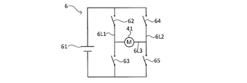
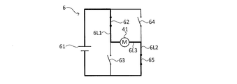
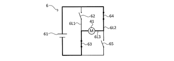
- the electric circuit 6 is a so-called H-bridge circuit.
- the electric circuit 6 realizes a plurality of states by switching a switch under the control of the control unit 44b. A plurality of states realized by the electric circuit 6 will be described later.
- the electric circuit 6 includes a power supply device 61, a first switch 62, a second switch 63, a third switch 64, a fourth switch 65, and an electric motor 41.
- the power supply device 61 is provided, for example, on the swivel table 12 (see FIG. 1).
- the first switch 62 is, for example, a transistor.
- the first switch 62 is provided on the first line 6L1.
- the first switch 62 is in either an ON state (state shown in FIG. 16B) or an OFF state (state shown in FIGS. 16A, 16C, and 16D) under the control of the control unit 44b (see FIG. 1). Can take the state of.
- the second switch 63 is, for example, a transistor.
- the second switch 63 is provided in series with the first switch 62 on the first line 6L1.
- the second switch 63 is provided on the first line 6L1 on the downstream side in the direction in which the current flows, with respect to the first switch 62.
- the second switch 63 Under the control of the control unit 44b (see FIG. 1), the second switch 63 is in either an ON state (state shown in FIGS. 16C and 16D) or an OFF state (state shown in FIGS. 16A and 16B). Can be taken.
- the third switch 64 is, for example, a transistor.
- the third switch 64 is provided on the second line 6L2.
- the second line 6L2 is in parallel with the first line 6L1.
- the third switch 64 is in either an ON state (state shown in FIG. 16C) or an OFF state (state shown in FIGS. 16A, 16B, and 16D) under the control of the control unit 44b (see FIG. 1). Can take the state of.
- the fourth switch 65 is, for example, a transistor.
- the fourth switch 65 is provided in series with the third switch 64 on the second line 6L2.
- the fourth switch 65 is provided on the second line 6L2 on the downstream side in the direction in which the current flows, with respect to the third switch 64.
- the fourth switch 65 Under the control of the control unit 44b (see FIG. 1), the fourth switch 65 is in either an ON state (state shown in FIGS. 16B and 16D) or an OFF state (state shown in FIGS. 16A and 16C). Can be taken.
- the configuration of the electric motor 41 is as described above.
- the electric motor 41 is provided on the third line 6L3.
- the third line 6L3 connects the portion between the first switch 62 and the second switch 63 in the first line 6L1 and the portion between the third switch 64 and the fourth switch 65 in the second line 6L2. are doing.
- the electric circuit 6 described above can have a non-energized state shown in FIG. 16A, a first driving state shown in FIG. 16B, a second driving state shown in FIG. 16C, and a braking state shown in FIG. 16D.
- the non-energized state of the electric circuit 6 is also referred to as a state in which the connection between the electric motor 41 and the power supply device 61 is disconnected (a state in which power supply from the power supply device 61 to the electric motor 41 is stopped. ).
- the switches 62, 63, 64, and 65 are in the OFF state.
- the first drive state of the electric circuit 6 is a state in which the electric motor 41 and the power supply device 61 are connected (also referred to as a state in which power supply from the power supply device 61 to the electric motor 41 is permitted). Is. In the first drive state of the electric circuit 6, the current flows through the circuit shown by the thick line in FIG. 16B.
- a current in the first direction flows through the electric motor 41.
- the first direction is the direction from the first line 6L1 to the second line 6L2.
- the electric motor 41 rotates in a first direction (the direction of arrow F 2 in Figure 18A ⁇ FIG 18C).
- the first switch 62 and the fourth switch 65 are in the ON state.
- the second switch 63 and the third switch 64 are in the OFF state.
- the first drive state corresponds to an example of the drive state of the electric circuit.
- the second drive state of the electric circuit 6 is a state in which the electric motor 41 and the power supply device 61 are connected (also referred to as a state in which power supply from the power supply device 61 to the electric motor 41 is permitted). Is. In the second drive state of the electric circuit 6, the current flows through the circuit shown by the thick line in FIG. 16C.
- a current in the second direction flows through the electric motor 41.
- the second direction is the direction from the second line 6L2 to the first line 6L1.
- the electric motor 41 rotates in a second direction (direction of the arrow F 1 in FIG. 19A ⁇ FIG 19C) (reversed).
- the second switch 63 and the third switch 64 are in the ON state.
- the first switch 62 and the fourth switch 65 are in the OFF state.
- the second drive state corresponds to an example of the drive state of the electric circuit.
- ⁇ Brake state> In the braking state of the electric circuit 6, as shown in FIG. 16D, the connection between the electric motor 41 and the power supply device 61 is released (power supply from the power supply device 61 to the electric motor 41 is stopped), and the electric circuit 6 is in a braking state.
- This is a state in which the closed circuit 66 (the portion shown by the thick line in FIG. 16D) is formed. That is, the electric circuit 6 has a closed circuit 66 in the braking state.
- the closed circuit 66 is a closed circuit including an electric motor 41, a second switch 63, and a fourth switch 65.
- the first switch 62 and the third switch 64 are in the OFF state. Further, in the braking state of the electric circuit 6, the second switch 63 and the fourth switch 65 are in the ON state. The operation of the electric circuit 6 will be described later.
- FIGS. 18A to 18C are schematic views for explaining the operation of the cylinder connecting mechanism 45.
- FIG. 18A is a schematic view showing an expanded state of the cylinder connecting mechanism 45 and an engaging state of a pair of cylinder connecting pins 454a and 454b and a pair of cylinder pin receiving portions 141a of the tip boom element 141.
- FIG. 18B is a schematic view showing a state in which the cylinder connecting mechanism 45 is in the process of transitioning from the expanded state to the contracted state.
- FIG. 18C is a schematic view showing a reduced state of the cylinder connecting mechanism 45 and a detached state of the pair of cylinder connecting pins 454a and 454b and the pair of cylinder pin receiving portions 141a of the tip boom element 141.
- the cylinder connecting mechanism 45 moves between an expanded state (see FIGS. 8, 12, and 18A) and a reduced state (see FIGS. 13 and 18C) based on the power (that is, rotational motion) of the electric motor 41. State transition.
- FIGS. 18A to 18C the operation of each part when the cylinder connecting mechanism 45 transitions from the expanded state to the contracted state will be described.
- the first missing tooth gear 450 and the second missing tooth gear 460 are schematically shown as an integrated missing tooth gear.
- this integrated missing tooth gear will be described as the first missing tooth gear 450.
- the lock mechanism 47 described later is omitted.
- the position of the first missing tooth gear 450 shown in FIG. 18A is defined as the reference position of the first missing tooth gear 450.
- the control unit 44b switches the electric circuit 6 to the first drive state (see FIG. 16B).
- the power of the electric motor 41 is transmitted to the pair of cylinder connecting pins 454a and 454b in the following first and second paths.
- the first path is the path of the first missing tooth gear 450 ⁇ the first rack bar 451 ⁇ the first gear mechanism 452 ⁇ one of the cylinder connecting pins 454a.
- the second path is the path of the first missing tooth gear 450 ⁇ the first rack bar 451 ⁇ the second gear mechanism 453 ⁇ the other cylinder connecting pin 454b.
- the first toothless gear 450 rotates in the forward rotational direction (direction shown in FIG. 18A by the arrow F 2) ..
- the pair of cylinder connecting pins 454a and 454b are separated from the pair of cylinder pin receiving portions 141a of the tip boom element 141, and are in predetermined positions (for example, the positions shown in FIGS. 2E and 18C). Detects that it has moved to. Then, based on the detection result, the control unit 44b stops the operation of the electric motor 41.
- the state transition from the reduced state to the expanded state of the cylinder connecting mechanism 45 (that is, the state transition from FIG. 18C to FIG. 18A) occurs when the brake mechanism 42 is released in the non-energized state of the electric motor 41. It is automatically performed based on the urging force of the urging mechanism 455. At this time, one cylinder connecting pin 454a and the other cylinder connecting pin 454b move in a direction away from each other.
- the control unit 44b switches the electric circuit 6 to the braking state (see FIG. 16D).
- the electric motor 41 idles based on the urging force of the first urging mechanism 455.
- the electric motor 41 generates electricity based on this idling.
- the current generated by the electric motor 41 passes through the closed circuit 66 and returns to the electric motor 41.
- Lorentz force is generated in the electric motor 41 based on the current returned to the electric motor 41.
- This Lorentz force acts as a braking force on the electric motor 41.
- one cylinder connecting pin 454a and the other cylinder connecting pin 454b stop at the reference position shown in FIG. 18A based on this braking force.
- the detailed operation of the electric circuit 6 will be described later.
- the pair of cylinder connecting pins 454a and 454b are engaged with the pair of cylinder pin receiving portions 141a of the tip boom element 141, and the positions shown in predetermined positions (for example, FIGS. 2A and 18A). ) Is detected. The detection result is used to control the next operation of the actuator 2.
- the boom connecting mechanism 46 corresponds to an example of the operating portion, and is referred to as an expanded state (also referred to as a first state; see FIGS. 8 and 13) and a reduced state (also referred to as a second state) based on the rotation of the electric motor 41.
- the state transitions to and from (see FIG. 12).
- the boom connecting mechanism 46 takes either an engaged state or a disengaged state with respect to the boom connecting pin (for example, a pair of boom connecting pins 144a) in the expanded state.
- the boom connecting mechanism 46 disengages the boom connecting pin from the boom element by transitioning from the expanded state to the contracted state while engaged with the boom connecting pin.
- the boom connecting mechanism 46 engages the boom connecting pin with the boom element by changing the state from the contracted state to the expanded state in the state of being engaged with the boom connecting pin.
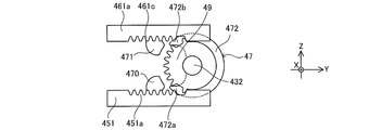
- the boom connecting mechanism 46 includes a second missing tooth gear 460, a pair of second rack bars 461a and 461b, a synchronous gear 462 (see FIGS. 18A to 18C), and a second urging mechanism 463.
- Each of the above elements 460, 461a, 461b, and 462 corresponds to an example of a constituent member of the second drive mechanism.
- the pair of boom connecting pins 144a and 144b also correspond to an example of the constituent members of the second drive mechanism.
- the second missing tooth gear 460 (also referred to as a switch gear) has a substantially circular ring plate shape, and has a second tooth portion 460a on a part of the outer peripheral surface in the circumferential direction.
- the second missing tooth gear 460 is externally fitted and fixed on the transmission shaft 432 in the X direction + side of the first missing tooth gear 450, and rotates together with the transmission shaft 432.
- the second missing tooth gear 460 may be a missing tooth gear integrated with the first missing tooth gear 450, for example, as shown in the schematic views shown in FIGS. 14A to 14D.
- the boom coupling mechanism 46 is extended state (FIG. 8, see FIG. 13) when the state transition to the reduced state (see FIG. 12) from the rotating direction (FIG. 8 of the second toothless gear 460 in an arrow F 1 Direction) is the "front side" in the rotation direction of the second missing tooth gear 460.
- the convex portion provided on the frontmost side in the rotation direction of the second missing tooth gear 460 is the positioning tooth 460b (see FIG. 8).
- FIG. 8 is a view of the pin movement module 4 viewed from the + side in the X direction. Therefore, in the case of the present embodiment, the front-rear direction in the rotation direction of the second missing tooth gear 460 is opposite to the front-rear direction in the rotation direction of the first missing tooth gear 450.
- the rotation direction of the second missing tooth gear 460 when the boom connecting mechanism 46 changes from the expanded state to the reduced state is the first missing tooth gear when the cylinder connecting mechanism 45 changes from the expanded state to the reduced state. It is opposite to the direction of rotation of 450.
- ⁇ Second rack bar> The pair of second rack bars 461a and 461b each move in the Y direction (also referred to as the axial direction) with the rotation of the second missing tooth gear 460.
- One second rack bar 461a is located most on the Y direction-side in the expanded state.
- the other second rack bar 461b is located on the + side in the Y direction most in the expanded state.
- one of the second rack bars 461a is located on the + side in the Y direction most in the reduced state.
- the other second rack bar 461b is located most on the Y-direction-side in the reduced state.
- the movement of one second rack bar 461a in the Y direction + side and the movement of the other second rack bar 461b in the Y direction-side are performed, for example, by the stopper surface 48 provided on the housing 40 (FIG. It is regulated by contact with (see 14D).
- the pair of second rack bars 461a and 461b are shaft members long in the Y direction, respectively, and are arranged parallel to each other.
- the pair of second rack bars 461a and 461b are respectively arranged on the + side in the Z direction with respect to the first rack bar 451. Further, the pair of second rack bars 461a and 461b are arranged around the synchronization gear 462 described later in the X direction.
- the longitudinal direction of each of the pair of second rack bars 461a and 461b coincides with the Y direction.
- the pair of second rack bars 461a and 461b have synchronous rack teeth 461e and 461f (see FIGS. 18A to 18C) on the side surfaces facing the X direction, respectively.
- the synchronous rack teeth 461e and 461f are respectively meshed with the synchronous gear 462.
- the pair of second rack bars 461a and 461b each have locking claw portions 461g and 461h (also referred to as locking portions, see FIG. 8) at the tip portions.
- locking claw portions 461g and 461h also referred to as locking portions, see FIG. 8
- the pin side receiving portions 144c see FIG. 8
- the second rack bar 461a has a drive rack tooth portion 461c (see FIG. 8) on the first side surface of the second missing tooth gear 460 (the side surface close to the second missing tooth gear 460).
- the drive rack tooth portion 461c meshes with the second tooth portion 460a of the second missing tooth gear 460.
- the first end surface 461d (Y direction + side end surface) of the drive rack tooth portion 461c comes into contact with the positioning tooth 460b at the second tooth portion 460a of the second missing tooth gear 460. Alternatively, they face each other in the Y direction through a slight gap.
- the positioning tooth 460b presses the first end surface 461d in the Y direction + side. With such pressing, one second rack bar 461a moves to the + side in the Y direction.
- the second urging mechanism 463 automatically returns the boom connecting mechanism 46 to the expanded state when the electric motor 41 is in the non-energized state in the reduced state of the boom connecting mechanism 46.
- the boom connecting mechanism 46 does not automatically return.
- the second urging mechanism 463 may be omitted. In this case, the boom connecting mechanism 46 may transition from the reduced state to the expanded state based on the power of the electric motor 41.
- the second urging mechanism 463 urges the pair of second rack bars 461a and 461b in a direction away from each other.
- the second urging mechanism 463 is composed of a pair of coil springs 463a and 463b (see FIGS. 18A to 17C).
- the pair of coil springs 463a and 463b urge the base end portions of the pair of second rack bars 461a and 461b toward the tip end side, respectively.
- the pair of coil springs 463a and 463b correspond to an example of the second urging member.
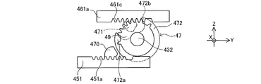
- FIGS. 19A to 19C are schematic views for explaining the operation of the boom connecting mechanism 46.
- FIG. 19A is a schematic view showing an expanded state of the boom connecting mechanism 46 and an engaging state of the pair of boom connecting pins 144a and the pair of first boom pin receiving portions 142b of the intermediate boom element 142.
- FIG. 19B is a schematic view showing a state in which the boom connecting mechanism 46 is in the process of transitioning from the expanded state to the contracted state.
- FIG. 19C is a schematic view showing a reduced state of the boom connecting mechanism 46 and a detached state of the pair of boom connecting pins 144a and the pair of first boom pin receiving portions 142b of the intermediate boom element 142.
- the boom connecting mechanism 46 as described above makes a state transition between an expanded state (see FIG. 19A) and a contracted state (see FIG. 19C) based on the power (that is, rotational motion) of the electric motor 41.
- the power that is, rotational motion
- the first missing tooth gear 450 and the second missing tooth gear 460 are schematically shown as an integrated missing tooth gear.
- this integrated missing tooth gear will be described as a second missing tooth gear 460.
- the position of the second missing tooth gear 460 shown in FIG. 19A is defined as the reference position of the second missing tooth gear 460.
- the lock mechanism 47 described later is omitted.
- the control unit 44b switches the electric circuit 6 to the second drive state (see FIG. 16C).
- the power of the electric motor 41 (that is, rotational movement) is transmitted through the path of the second missing tooth gear 460 ⁇ one second rack bar 461a ⁇ synchronous gear 462 ⁇ the other second rack bar 461b.
- the second toothless gear 460 rotates in the forward rotational direction (direction shown in FIGS. 8 and 19A ⁇ FIG 19C by the arrow F 1).
- the synchronous gear 462 rotates according to the movement of one of the second rack bars 461a in the Y direction + side. Then, in response to the rotation of the synchronous gear 462, the other second rack bar 461b moves in the Y direction ⁇ side (left side in FIGS. 19A to 19C).
- the pair of boom connecting pins 144a becomes the pair of first of the intermediate boom elements 142. It separates from the boom pin receiving portion 142b (see FIG. 19C).
- the pair of boom connecting pins 144a is separated from the pair of first boom pin receiving portions 142b of the intermediate boom element 142 and reaches a predetermined position (for example, the position shown in FIGS. 2B and 19C). Detect that it has moved. Then, based on this detection result, the control unit 44b stops the operation of the electric motor 41.
- the closing operation of the boom connecting mechanism 46 (that is, the state transition from FIG. 19C to FIG. 19A) is the urging force of the second urging mechanism 463 when the brake mechanism 42 is released in the non-energized state of the electric motor 41. It is done automatically based on. At the time of this state transition, the pair of boom connecting pins 144a move in a direction away from each other.
- the control unit 44b switches the electric circuit 6 to the braking state (see FIG. 16D). Then, when the electric circuit 6 is switched to the closed circuit 66, the above-mentioned braking force is generated in the electric motor 41. As a result, each of the pair of boom connecting pins 144a stops at the reference position shown in FIG. 19A based on this braking force. The operation of the electric circuit 6 will be described later.
- the pair of boom connecting pins 144a engages with the pair of first boom pin receiving portions 142b of the intermediate boom element 142, and the position information detection device 44 has a predetermined position (for example, the position shown in FIGS. 2A and 19A). Detects that it has moved to. The detection result is used to control the next operation of the actuator 2.
- the boom connecting mechanism 46 when the first tooth portion 450a of the first missing tooth gear 450 meshes with the first rack tooth portion 451a of the first rack bar 451, the boom connecting mechanism 46 The second tooth portion 460a of the second missing tooth gear 460 does not mesh with the drive rack tooth portion 461c of one of the second rack bars 461a.
- the operating portion is the cylinder connecting mechanism 45 and the boom connecting mechanism 46 described above.
- the operating portion is not limited to the cylinder connecting mechanism 45 and the boom connecting mechanism 46.
- the actuating part may be various mechanisms that act on the power of an electrical drive source.
- the actuator 2 has the cylinder connecting pin removed in one boom element (for example, the tip boom element 141) based on the configuration of the boom connecting mechanism 46 and the cylinder connecting mechanism 45.
- the state in which the boom connecting pin is pulled out is not realized at the same time.
- Such a configuration prevents the boom connecting mechanism 46 and the cylinder connecting mechanism 45 from operating at the same time based on the power of the electric motor 41.
- the actuator 2 has an external force other than the electric motor 41 on the cylinder connecting mechanism 45 (for example, the first rack bar 451) or the boom connecting mechanism 46 (for example, the second rack bar 461a).
- Has a lock mechanism 47 that prevents the cylinder connecting mechanism 45 and the boom connecting mechanism 46 from transitioning to each other at the same time when
- Such a lock mechanism 47 prevents the operation of the other coupling mechanism while one of the boom coupling mechanism 46 and the cylinder coupling mechanism 45 is operating.
- the specific structure of the lock mechanism 47 will be described with reference to FIGS. 14A to 14D.
- 14A to 14D are schematic views for explaining the structure of the lock mechanism 47.
- an integrated missing gear 49 (also referred to as a switch gear) in which the first missing gear 450 of the cylinder connecting mechanism 45 and the second missing gear 460 of the boom connecting mechanism 46 are integrally formed. ).
- Such an integrated missing tooth gear 49 has a substantially circular ring plate shape, and has a tooth portion 49a on a part of the outer peripheral surface. The structure of other parts is the same as the structure of the present embodiment described above.
- the lock mechanism 47 has a first convex portion 470, a second convex portion 471, and a cam member 472 (also referred to as a lock side rotating member).
- the first convex portion 470 is integrally provided with the first rack bar 451 of the cylinder connecting mechanism 45. Specifically, the first convex portion 470 is provided at a position adjacent to the first rack tooth portion 451a of the first rack bar 451.
- the second convex portion 471 is integrally provided with one of the second rack bars 461a of the boom connecting mechanism 46. Specifically, the second convex portion 471 is provided at a position adjacent to the drive rack tooth portion 461c of one of the second rack bars 461a.
- the cam member 472 is a plate-shaped member having a substantially crescent shape. Such a cam member 472 has a first cam receiving portion 472a at one end in the circumferential direction. On the other hand, the cam member 472 has a second cam receiving portion 472b at the other end in the circumferential direction.
- the cam member 472 may be externally fitted and fixed at a position shifted in the X direction from the position where the integrated missing tooth gear 49 is externally fixed, for example, on the transmission shaft 432.
- the cam member 472 is externally fitted and fixed between the first missing tooth gear 450 and the second missing tooth gear 460. That is, the cam member 472 and the integrated missing tooth gear 49 are provided coaxially.
- Such a cam member 472 rotates together with the transmission shaft 432. Therefore, the cam member 472 rotates around the central axis of the transmission shaft 432 together with the integrated missing tooth gear 49.
- the cam member 472 may be integrated with the integrated missing tooth gear 49. Further, in the case of the present embodiment, the cam member 472 may be integrated with at least one of the first missing gear 450 and the second missing gear 460.
- the tooth portion 49a of the integrated missing tooth gear 49 (also the second tooth portion 460a of the second missing tooth gear 460) is one of the second rack bars.
- the first cam receiving portion 472a of the cam member 472 is located on the + side in the Y direction with respect to the first convex portion 470 in a state of being meshed with the drive rack tooth portion 461c of the 461a.
- the tooth portion 49a of the integrated missing gear 49 does not mesh with the first rack tooth portion 451a of the first rack bar 451.
- the first cam receiving portion 472a and the first convex portion 470 face each other with a slight gap in the Y direction (see FIG. 15A).
- the first rack bar 451 Y-direction + side of the external force force indicated by the arrow F a in FIG. 15A
- the movement of the Y-direction + side of the first rack bar 451 is prevented To.
- the tooth portion 49a of the integrated missing tooth gear 49 (the first tooth portion 450a of the first missing tooth gear 450 in the cylinder connecting mechanism 45) is the first of the first rack bar 451.
- the second cam receiving portion 472b of the cam member 472 is located on the + side in the Y direction with respect to the second convex portion 471.
- the electric circuit 6 may take any one of the above-mentioned non-energized state, first drive state, second drive state, and braking state.
- First drive state Specifically, in the electric circuit 6, when the cylinder connecting mechanism 45 (also referred to as the first connecting mechanism) changes from the expanded state to the contracted state (hereinafter, also referred to as “pulling operation of the cylinder connecting mechanism 45”). In the first drive state (see FIG. 16B). In other words, the control unit 44b switches the electric circuit 6 to the first drive state in the pulling operation of the cylinder connecting mechanism 45.
- the electric circuit 6 is used when the boom connecting mechanism 46 (also referred to as a second connecting mechanism) undergoes a state transition from an expanded state to a contracted state (hereinafter, also referred to as “pulling operation of the boom connecting mechanism 46”). It is in the second drive state (see FIG. 16C). In other words, the control unit 44b switches the electric circuit 6 to the second drive state in the pulling operation of the boom connecting mechanism 46.
- the electric motor 41 idles based on the urging force of the second urging mechanism 463.
- the electric motor 41 generates electricity based on this idling.
- the current generated by the electric motor 41 passes through the closed circuit 66 and returns to the electric motor 41.
- Lorentz force is generated in the electric motor 41 based on the current returned to the electric motor 41.
- This Lorentz force acts as a braking force on the electric motor 41.
- the current is converted into thermal energy by a resistor (not shown) provided in the closed circuit 66.
- the braking force as described above is adjusted according to the resistance value of the closed circuit 66. As an example, the resistance value may be adjusted manually by the operator.
- the braking force as described above contributes to the prevention of overrun of the second missing tooth gear 460 (see FIGS. 19A to 19C) in the engaging operation of the boom connecting mechanism 46. The reason for this will be described with reference to FIGS. 19A to 19C.
- the second missing tooth gear 460 idles based on the rotation.
- the electric motor 41 generates electricity based on this idling.
- the current generated by the electric motor 41 passes through the closed circuit 66 and returns to the electric motor 41.
- Lorentz force is generated in the electric motor 41 based on the current returned to the electric motor 41.
- This Lorentz force acts as a braking force on the electric motor 41.
- the current is converted into thermal energy by a resistor (not shown) provided in the closed circuit 66.
- a braking force also acts on the second missing tooth gear 460 as a resistance force against the rotation of the second missing tooth gear 460.
- the second missing tooth gear 460 stops at the reference position shown in FIG. 19A.
- the force in the pulling operation direction does not act on the cylinder connecting mechanism 45.
- the force in the pulling operation direction means a force that causes the cylinder connecting mechanism 45 to transition from the state shown in FIG. 18A to the state shown in FIG. 18B.
- the idling of the electric motor 41 is also stopped, so that the above-mentioned braking force is not generated. Therefore, the above-mentioned braking force does not act on the second missing tooth gear 460 in the stopped state.
- the braking force described above is a force that stops the cylinder connecting pin 454a, 454b and the boom connecting pin 144a at positions other than the first end and the second end in the stroke of the cylinder connecting pin 454a, 454b and the boom connecting pin 144a. Does not have.
- the first end of the stroke corresponds to a position (position shown in FIGS. 18A and 19A) corresponding to the inserted state of the cylinder connecting pin 454a, 454b and the boom connecting pin 144a.
- the second end of the stroke corresponds to a position (position shown in FIGS. 18C and 19C) corresponding to the removed state of the cylinder connecting pin 454a, 454b and the boom connecting pin 144a.
- the cylinder connecting pins 454a and 454b and the boom connecting pin 144a do not stop in the middle of the operation (that is, at positions other than both ends in the stroke). If the cylinder connecting pin 454a, 454b and the boom connecting pin 144a stop in the middle of operation, it may cause a failure. According to the present embodiment, it is possible to prevent the cylinder connecting pin 454a, 454b and the boom connecting pin 144a from stopping at a position that causes such a failure, so that the cylinder connecting mechanism 45, the boom connecting mechanism 46, and the boom connecting mechanism 46, by extension, , The failure of the mobile crane 1 can be suppressed.
- the electric motor 41 idles based on the urging force of the first urging mechanism 455.
- the electric motor 41 generates electricity based on this idling.
- the current generated by the electric motor 41 passes through the closed circuit 66 and returns to the electric motor 41.
- Lorentz force is generated in the electric motor 41 based on the current returned to the electric motor 41. This Lorentz force acts as a braking force on the electric motor 41.
- Such braking force contributes to the prevention of overrun of the first missing tooth gear 450 in the engaging operation of the cylinder connecting mechanism 45.
- the reason for this is the same as in the case of the boom connecting mechanism 46 described above, and thus description thereof will be omitted.
- FIG. 17 is a timing chart of the telescopic boom 14 when the tip boom element 141 is extended.
- the actuator 2 switches the rotation direction of one electric motor 41 and distributes the driving force of the electric motor 41 to the cylinder connecting mechanism 45 and the boom connecting mechanism 46 (that is, the first missing switch gear).
- the tooth gear 450 and the second missing tooth gear 460 With the tooth gear 450 and the second missing tooth gear 460), the pulling operation of the cylinder connecting pin 454a and 454b and the pulling operation of the boom connecting pin 144a are selectively realized.
- the contraction operation of the tip boom element 141 is the reverse of the procedure of the expansion / contraction operation described below.
- the ON / OFF switching of the electric motor 41 and the ON / OFF switching of the brake mechanism 42 are controlled by the control unit based on the output of the position information detection device 44 described above.
- FIG. 2A shows the contracted state of the telescopic boom 14.
- the tip boom element 141 is connected to the intermediate boom element 142 via the boom connecting pin 144a. Therefore, the tip boom element 141 cannot move in the longitudinal direction (left-right direction of FIGS. 2A to 2E) with respect to the intermediate boom element 142.
- the tip portions of the cylinder connecting pins 454a and 454b engage with the pair of cylinder pin receiving portions 141a of the tip boom element 141. That is, the tip boom element 141 and the cylinder member 32 are in a connected state.
- the electric motor 41 is rotated in the normal direction (rotated in the first direction which is the clockwise direction when viewed from the tip side of the output shaft), and the pair is formed by the boom connecting mechanism 46 of the actuator 2.
- the boom connecting pin 144a is moved in a direction away from the pair of first boom pin receiving portions 142b of the intermediate boom element 142.
- the boom connecting mechanism 46 makes a state transition from the expanded state to the contracted state.
- the pair of boom connecting pins 144a and the pair of first boom pin receiving portions 142b of the intermediate boom element 142 are disengaged (see FIG. 2B).
- the brake mechanism 42 is turned on and the electric motor 41 is turned off.
- the timing of turning off the electric motor 41 and the timing of turning on the brake mechanism 42 are appropriately controlled by the control unit. For example, although not shown, the electric motor 41 is turned off after the brake mechanism 42 is turned on.
- the tip boom element 141 moves in the extension direction (see FIG. 2C). At this time, as for the state of each part, the state of T2 in FIG. 17 is maintained until T3.
- the brake mechanism 42 is released. Then, based on the urging force of the second urging mechanism 463, the boom connecting mechanism 46 moves the pair of boom connecting pins 144a in the direction of engaging the pair of second boom pin receiving portions 142c of the intermediate boom element 142. At this time, the boom connecting mechanism 46 makes a state transition (that is, automatic return) from the contracted state to the expanded state. That is, the boom connecting mechanism 46 is turned on.
- a state transition that is, automatic return
- the electric circuit 6 described above is in a braking state (see FIG. 16D).
- the electric circuit 6 is switched to the closed circuit 66, so that the braking force as described above acts on the electric motor 41.
- Each of the pair of boom connecting pins 144a stops at the reference position of the boom connecting pins 144a shown in FIG. 19A based on this braking force.
- the pair of boom connecting pins 144a engages with the pair of second boom pin receiving portions 142c of the intermediate boom element 142.
- the electric motor 41 is reversed (rotated in the second direction which is the counterclockwise direction when viewed from the tip side of the output shaft), and the cylinder connecting mechanism 45 causes a pair of cylinder connecting pins.
- the 454a and 454b are moved in a direction away from the pair of cylinder pin receiving portions 141a of the tip boom element 141.
- the cylinder connecting mechanism 45 makes a state transition from the expanded state to the reduced state.
- the electric circuit 6 described above is in a braking state (see FIG. 16D). Then, when the electric circuit 6 is switched to the closed circuit 66, the above-mentioned braking force is generated in the electric motor 41. When this braking force acts on the electric motor 41, the pair of cylinder connecting pins 454a and 454b each stop at the reference position shown in FIG. 18A based on this braking force. In this way, since the overrun of the first missing tooth gear 450 (see FIG. 18A) of the cylinder connecting mechanism 45 is prevented, a force acts on the boom connecting mechanism 46 in the direction of transitioning from the expanded state to the contracted state. There is no such thing.
- the cylinder connecting mechanism 45 and the boom connecting mechanism 46 are electric, it is not necessary to provide a hydraulic circuit in the internal space of the telescopic boom 14 as in the conventional structure. Therefore, the space used by the hydraulic circuit can be effectively utilized to improve the degree of freedom in designing the internal space of the telescopic boom 14.
- the positions of the cylinder connecting pins 454a and 454b and the boom connecting pins 144a and 144b are detected by the above-mentioned position information detecting device 44. Therefore, in the present embodiment, the proximity sensor for detecting the positions of the cylinder connecting pins 454a and 454b and the boom connecting pins 144a and 144b becomes unnecessary. Such a proximity sensor is provided at a position where, for example, the cylinder connecting pin 454a, 454b and the boom connecting pin 144a, 144b can detect the inserted state and the disconnected state, respectively.
- the cylinder connecting pins 454a and 454b and the boom connecting pins 144a and 144b are respectively provided by the position information detecting device 44 (that is, one detector) including one detecting unit 44a as described above. The position of can be detected.
- the working machine is Actuators that expand and contract the telescopic boom, and An electrical drive source provided in the actuator and driven based on the power supply from the power supply, It is provided with a working unit that operates based on the power of an electric drive source as a basic configuration.
- the working machine is additionally used. Braking that allows power supply from the power source to the electric drive source and drives the electric drive source, and stops power supply from the power source to the electric drive source to generate braking force applied to the electric drive source.
- An electric circuit that can switch between states and A control unit that controls switching between a driving state and a braking state may be provided.
- the boom may additionally have a first boom element and a second boom element that are stretchably overlapped with each other.
- the operating portion when carrying out the present invention, additionally A first coupling mechanism that operates based on the power of an electrical drive source and switches between a connected state and a non-connected state of the first boom element and the actuator. It may be provided with a second connecting mechanism that operates based on the power of an electric drive source and switches between a connected state and a non-connected state of the first boom element and the second boom element.
- the working machine according to an example of the reference example of the present invention may include an arbitrary configuration selected from the configuration of the working machine described in the above-described embodiment in addition to the above-mentioned basic configuration.
- the working machine according to such a reference example is not limited to a crane, and may be various working machines provided with a telescopic boom.
- the crane according to the present invention is not limited to a rough terrain crane, and may be, for example, various mobile cranes such as an all-terrain crane, a truck crane, or a loaded truck crane (also referred to as a cargo crane). Further, the crane according to the present invention is not limited to a mobile crane, and may be another crane provided with a telescopic boom.
Abstract
This work machine comprises: an actuator that extends and retracts a telescopic boom; an electric drive source that is provided to the actuator and driven by power supplied from a power source; an operating unit that operates with energy from the electric drive source; an electric circuit capable of switching between a drive state in which power is allowed to be supplied to the electric drive source from the power source to drive the electric drive source, and a braking state in which the supply of power from the power source to the electric drive source is stopped and a braking force to be applied to the electric drive source is generated; and a control unit that controls the switching between the drive state and the braking state.
Description
本発明は、伸縮式ブームを備える作業機に関する。
The present invention relates to a working machine provided with a telescopic boom.
特許文献1には、複数のブーム要素が入れ子状(テレスコピック状ともいう。)に重なる伸縮式ブーム、及び、伸縮式ブームを伸長させる油圧式の伸縮シリンダを備えた移動式のクレーンが開示されている。
Patent Document 1 discloses a telescopic boom in which a plurality of boom elements are nested (also referred to as a telescopic shape), and a mobile crane including a hydraulic telescopic cylinder for extending the telescopic boom. There is.
伸縮式ブームは、隣り合って重なるブーム要素同士を連結するブーム連結ピンを有する。ブーム連結ピンによる連結が解除されたブーム要素(以下、移動可能なブーム要素という。)は、他のブーム要素に対して長手方向(伸縮方向ともいう。)に移動可能となる。
The telescopic boom has a boom connecting pin that connects adjacent and overlapping boom elements. The boom element (hereinafter referred to as a movable boom element) that has been disconnected by the boom connecting pin can move in the longitudinal direction (also referred to as expansion / contraction direction) with respect to other boom elements.
伸縮シリンダは、ロッド部材及びシリンダ部材を有する。このような伸縮シリンダは、シリンダ連結ピンを介して上記移動可能なブーム要素にシリンダ部材を連結する。この状態でシリンダ部材が伸縮方向に移動すると、当該シリンダ部材とともに上記移動可能なブーム要素が移動して伸縮式ブームが伸縮する。
The telescopic cylinder has a rod member and a cylinder member. Such a telescopic cylinder connects a cylinder member to the movable boom element via a cylinder connecting pin. When the cylinder member moves in the expansion / contraction direction in this state, the movable boom element moves together with the cylinder member to expand / contract the telescopic boom.
ところで、上述のようなクレーンは、ブーム連結ピンを移動させる油圧式のアクチュエータ、シリンダ連結ピンを移動させる油圧式のアクチュエータ、及び、これら各アクチュエータに圧油を供給する油圧回路を備える。このような油圧回路は、例えば伸縮式ブームの周囲に設けられる。このため、伸縮式ブームの周囲における設計の自由度が低下する可能性がある。
By the way, the crane as described above includes a hydraulic actuator for moving the boom connecting pin, a hydraulic actuator for moving the cylinder connecting pin, and a hydraulic circuit for supplying pressure oil to each of these actuators. Such a hydraulic circuit is provided, for example, around a telescopic boom. This can reduce the degree of freedom in design around the telescopic boom.
本発明の目的は、伸縮式ブームの周囲における設計の自由度を向上できる作業機を提供することである。
An object of the present invention is to provide a working machine capable of improving the degree of freedom in design around the telescopic boom.
本発明に係る作業機は、
伸縮式のブームを伸縮させるアクチュエータと、
アクチュエータに設けられ、電源からの給電に基づいて駆動する電気的駆動源と、
電気的駆動源の動力に基づいて作動する作動部と、
電源から電気的駆動源への給電を許可し、電気的駆動源を駆動する駆動状態と、電源から電気的駆動源への給電を停止し、電気的駆動源に付与する制動力を生成する制動状態と、を切り換え可能な電気回路と、
駆動状態と制動状態との切り換えを制御する制御部と、を備える。 The working machine according to the present invention is
Actuators that expand and contract the telescopic boom, and
An electrical drive source provided in the actuator and driven based on the power supply from the power supply,
An actuating part that operates based on the power of an electrical drive source,
Braking that allows power supply from the power source to the electric drive source and drives the electric drive source, and stops power supply from the power source to the electric drive source to generate braking force applied to the electric drive source. An electric circuit that can switch between states and
It is provided with a control unit that controls switching between a driving state and a braking state.
本発明によれば、伸縮式ブームの周囲における設計の自由度を向上できる。
According to the present invention, the degree of freedom in design around the telescopic boom can be improved.
以下、本発明に係る実施形態の一例を図面に基づいて詳細に説明する。なお、後述の実施形態に係るクレーンは、本発明に係る作業機の一例であり、本発明は後述の実施形態により限定されない。
Hereinafter, an example of the embodiment according to the present invention will be described in detail with reference to the drawings. The crane according to the embodiment described later is an example of the working machine according to the present invention, and the present invention is not limited to the embodiment described later.
[実施形態]
図1は、本実施形態に係る移動式クレーン1(図示の場合、ラフテレーンクレーン)の模式図である。移動式クレーン1は、作業機の一例に該当する。 [Embodiment]
FIG. 1 is a schematic view of a mobile crane 1 (rough terrain crane in the case of illustration) according to the present embodiment. Themobile crane 1 corresponds to an example of a working machine.
図1は、本実施形態に係る移動式クレーン1(図示の場合、ラフテレーンクレーン)の模式図である。移動式クレーン1は、作業機の一例に該当する。 [Embodiment]
FIG. 1 is a schematic view of a mobile crane 1 (rough terrain crane in the case of illustration) according to the present embodiment. The
移動式クレーンとして、例えば、オールテレーンクレーン、トラッククレーン、あるいは、積載形トラッククレーン(カーゴクレーンともいう。)が挙げられる。ただし、本発明に係る作業機は、移動式クレーンに限定されず、伸縮式のブームを備えるその他の作業車(例えば、クレーン、高所作業車)にも適用できる。
Examples of mobile cranes include all-terrain cranes, truck cranes, and loaded truck cranes (also referred to as cargo cranes). However, the work machine according to the present invention is not limited to the mobile crane, and can be applied to other work vehicles (for example, cranes, aerial work platforms) having a telescopic boom.
以下、まず、移動式クレーン1及び移動式クレーン1が備える伸縮式ブーム14の概要について説明する。その後、本実施形態に係る移動式クレーン1の特徴であるアクチュエータ2の具体的な構造及び動作について説明する。
Hereinafter, first, the outline of the mobile crane 1 and the telescopic boom 14 included in the mobile crane 1 will be described. After that, the specific structure and operation of the actuator 2, which is a feature of the mobile crane 1 according to the present embodiment, will be described.
<移動式クレーン>
図1に示すように、移動式クレーン1は、走行体10と、アウトリガ11と、旋回台12と、伸縮式ブーム14と、アクチュエータ2(図1には省略)と、電気回路6(図16A~図16D参照)と、起伏シリンダ15と、ワイヤ16と、フック17と、を有する。 <Mobile crane>
As shown in FIG. 1, themobile crane 1 includes a traveling body 10, an outrigger 11, a swivel base 12, a telescopic boom 14, an actuator 2 (omitted in FIG. 1), and an electric circuit 6 (FIG. 16A). (See FIG. 16D), an undulating cylinder 15, a wire 16, and a hook 17.
図1に示すように、移動式クレーン1は、走行体10と、アウトリガ11と、旋回台12と、伸縮式ブーム14と、アクチュエータ2(図1には省略)と、電気回路6(図16A~図16D参照)と、起伏シリンダ15と、ワイヤ16と、フック17と、を有する。 <Mobile crane>
As shown in FIG. 1, the
走行体10は、複数個の車輪101を有する。アウトリガ11は、走行体10の四隅に設けられている。旋回台12は、走行体10の上部に旋回可能に設けられている。伸縮式ブーム14は、基端部が旋回台12に固定されている。アクチュエータ2は、伸縮式ブーム14を伸縮する。起伏シリンダ15は、伸縮式ブーム14を起伏する。ワイヤ16は、伸縮式ブーム14の先端部から垂れ下がっている。フック17は、ワイヤ16の先端に設けられている。
The traveling body 10 has a plurality of wheels 101. Outriggers 11 are provided at the four corners of the traveling body 10. The swivel base 12 is provided on the upper portion of the traveling body 10 so as to be swivelable. The base end of the telescopic boom 14 is fixed to the swivel base 12. The actuator 2 expands and contracts the telescopic boom 14. The undulating cylinder 15 undulates the telescopic boom 14. The wire 16 hangs down from the tip of the telescopic boom 14. The hook 17 is provided at the tip of the wire 16.
<伸縮式ブーム>
次に、図1、図2A~図2Eを参照して、伸縮式ブーム14について説明する。図2A~図2Eは、伸縮式ブーム14の構造及び伸縮動作を説明するための模式図である。 <Expandable boom>
Next, thetelescopic boom 14 will be described with reference to FIGS. 1 and 2A to 2E. 2A to 2E are schematic views for explaining the structure and expansion / contraction operation of the telescopic boom 14.
次に、図1、図2A~図2Eを参照して、伸縮式ブーム14について説明する。図2A~図2Eは、伸縮式ブーム14の構造及び伸縮動作を説明するための模式図である。 <Expandable boom>
Next, the
図1には、伸長状態の伸縮式ブーム14が示されている。図2Aには、収縮状態の伸縮式ブーム14が示されている。図2Eには、後述の先端ブーム要素141のみが伸長した伸縮式ブーム14が示されている。
FIG. 1 shows a telescopic boom 14 in an extended state. FIG. 2A shows a telescopic boom 14 in a contracted state. FIG. 2E shows a telescopic boom 14 in which only the tip boom element 141, which will be described later, is extended.
伸縮式ブーム14は、複数のブーム要素からなる。複数のブーム要素はそれぞれ、筒状である。複数のブーム要素は、互いに、テレスコピック状に組み合わされている。具体的には、収縮状態において、複数のブーム要素は、内側から順に先端ブーム要素141、中間ブーム要素142、及び、基端ブーム要素143である。
The telescopic boom 14 is composed of a plurality of boom elements. Each of the boom elements is tubular. The boom elements are telescopically combined with each other. Specifically, in the contracted state, the plurality of boom elements are the tip boom element 141, the intermediate boom element 142, and the proximal boom element 143 in order from the inside.
なお、本実施形態の場合、先端ブーム要素141及び中間ブーム要素142が、伸縮方向に移動可能な第一ブーム要素の一例に該当する。先端ブーム要素141が、中間ブーム要素142に対して伸縮方向に移動する場合には、先端ブーム要素141が第一ブーム要素の一例に該当し、中間ブーム要素142が第二ブーム要素の一例に該当する。また、中間ブーム要素142が、基端ブーム要素143に対して伸縮方向に移動する場合には、中間ブーム要素142が、第一ブーム要素の一例に該当し、基端ブーム要素143が第二ブーム要素の一例に該当する。基端ブーム要素143は、伸縮方向への移動が規制されている。
In the case of the present embodiment, the tip boom element 141 and the intermediate boom element 142 correspond to an example of the first boom element that can move in the expansion / contraction direction. When the tip boom element 141 moves in the expansion / contraction direction with respect to the intermediate boom element 142, the tip boom element 141 corresponds to an example of the first boom element, and the intermediate boom element 142 corresponds to an example of the second boom element. To do. Further, when the intermediate boom element 142 moves in the expansion / contraction direction with respect to the proximal boom element 143, the intermediate boom element 142 corresponds to an example of the first boom element, and the proximal boom element 143 corresponds to the second boom. Corresponds to an example of an element. The base end boom element 143 is restricted from moving in the expansion / contraction direction.
伸縮式ブーム14は、内側に配置されたブーム要素(つまり、先端ブーム要素141)から順に伸長することにより、図2Aに示す収縮状態から図1に示す伸長状態に状態遷移する。
By extending the telescopic boom 14 in order from the boom element (that is, the tip boom element 141) arranged inside, the state transitions from the contracted state shown in FIG. 2A to the extended state shown in FIG.
伸長状態において、最も基端側の基端ブーム要素143と最も先端側の先端ブーム要素141との間に、中間ブーム要素142が配置されている。なお、中間ブーム要素は、複数でもよい。
In the extended state, the intermediate boom element 142 is arranged between the proximal end boom element 143 on the most proximal end side and the distal boom element 141 on the most distal end side. The number of intermediate boom elements may be plural.
伸縮式ブーム14の構造は、従来から知られている伸縮式ブームの構造とほぼ同様であるが、後述のアクチュエータ2の構造及び動作に関する説明の便宜のため、以下、先端ブーム要素141及び中間ブーム要素142の構造について説明する。
The structure of the telescopic boom 14 is almost the same as the structure of the conventionally known telescopic boom, but for convenience of explanation regarding the structure and operation of the actuator 2 described later, the tip boom element 141 and the intermediate boom are described below. The structure of the element 142 will be described.
<先端ブーム要素>
先端ブーム要素141は、図2A~図2Eに示すような筒状である。先端ブーム要素141は、アクチュエータ2を収容可能な内部空間を有する。先端ブーム要素141は、基端部に、一対のシリンダピン受部141a及び一対のブームピン受部141bを有する。 <Tip boom element>
Thetip boom element 141 has a tubular shape as shown in FIGS. 2A to 2E. The tip boom element 141 has an internal space that can accommodate the actuator 2. The tip boom element 141 has a pair of cylinder pin receiving portions 141a and a pair of boom pin receiving portions 141b at the base end portion.
先端ブーム要素141は、図2A~図2Eに示すような筒状である。先端ブーム要素141は、アクチュエータ2を収容可能な内部空間を有する。先端ブーム要素141は、基端部に、一対のシリンダピン受部141a及び一対のブームピン受部141bを有する。 <Tip boom element>
The
一対のシリンダピン受部141aは、先端ブーム要素141の基端部に、互いに同軸に設けられている。一対のシリンダピン受部141aはそれぞれ、伸縮シリンダ3のシリンダ部材32に設けられた一対のシリンダ連結ピン454a、454b(第一連結部材ともいう。)と係脱可能である。つまり、一対のシリンダピン受部141aは、一対のシリンダ連結ピン454a、454bと係合する係合状態、及び、一対のシリンダ連結ピン454a、454bとの係合が解除された離脱状態の何れか一方の状態を取り得る。
The pair of cylinder pin receiving portions 141a are provided coaxially with each other at the base end portion of the tip boom element 141. Each of the pair of cylinder pin receiving portions 141a can be engaged with and detached from the pair of cylinder connecting pins 454a and 454b (also referred to as the first connecting member) provided in the cylinder member 32 of the telescopic cylinder 3. That is, either the pair of cylinder pin receiving portions 141a is engaged with the pair of cylinder connecting pins 454a and 454b, or the pair of cylinder pin receiving portions 141a is disengaged with the pair of cylinder connecting pins 454a and 454b. It can take one state.
シリンダ連結ピン454a、454bは、後述のアクチュエータ2が備えるシリンダ連結機構45の作動に基づいて、自身の軸方向に移動する。一対のシリンダ連結ピン454a、454bと一対のシリンダピン受部141aとが係合した状態で、先端ブーム要素141は、シリンダ部材32とともに伸縮方向に移動可能である。
The cylinder connecting pins 454a and 454b move in their own axial direction based on the operation of the cylinder connecting mechanism 45 included in the actuator 2 described later. With the pair of cylinder connecting pins 454a and 454b engaged with the pair of cylinder pin receiving portions 141a, the tip boom element 141 can move in the expansion / contraction direction together with the cylinder member 32.
一対のブームピン受部141bは、シリンダピン受部141aよりも基端側に、互いに同軸に設けられている。ブームピン受部141bはそれぞれ、一対のブーム連結ピン144a(第二連結部材ともいう。)と係脱可能である。つまり、一対のブームピン受部141bは、一対のブーム連結ピン144aと係合する係合状態、及び、一対のブーム連結ピン144aとの係合が解除された離脱状態の何れか一方の状態を取り得る。
The pair of boom pin receiving portions 141b are provided coaxially with each other on the proximal end side of the cylinder pin receiving portion 141a. Each of the boom pin receiving portions 141b can be engaged with and detached from the pair of boom connecting pins 144a (also referred to as a second connecting member). That is, the pair of boom pin receiving portions 141b takes either an engaged state of engaging with the pair of boom connecting pins 144a and a disengaged state of being disengaged with the pair of boom connecting pins 144a. obtain.
一対のブーム連結ピン144aはそれぞれ、先端ブーム要素141と中間ブーム要素142とを連結する。一対のブーム連結ピン144aは、アクチュエータ2が備えるブーム連結機構46の作動に基づいて、自身の軸方向に移動する。一対のブーム連結ピン144aは、ブーム連結機構46の構成部材と捉えてもよい。
The pair of boom connecting pins 144a connect the tip boom element 141 and the intermediate boom element 142, respectively. The pair of boom connecting pins 144a move in their own axial direction based on the operation of the boom connecting mechanism 46 included in the actuator 2. The pair of boom connecting pins 144a may be regarded as constituent members of the boom connecting mechanism 46.
先端ブーム要素141と中間ブーム要素142とが一対のブーム連結ピン144aにより連結された状態で、先端ブーム要素141のブームピン受部141bと、後述の中間ブーム要素142の第一ブームピン受部142b又は第二ブームピン受部142cとに、ブーム連結ピン144aが架け渡されるように挿通される。
With the tip boom element 141 and the intermediate boom element 142 connected by a pair of boom connecting pins 144a, the boom pin receiving portion 141b of the tip boom element 141 and the first boom pin receiving portion 142b or the first boom pin receiving portion 142b of the intermediate boom element 142 described later The boom connecting pin 144a is inserted through the boom pin receiving portion 142c so as to be bridged.
先端ブーム要素141と中間ブーム要素142とが連結した状態(連結状態ともいう。)において、先端ブーム要素141は、中間ブーム要素142に対する伸縮方向への移動が禁止される。
In a state where the tip boom element 141 and the intermediate boom element 142 are connected (also referred to as a connected state), the tip boom element 141 is prohibited from moving in the expansion / contraction direction with respect to the intermediate boom element 142.
一方、先端ブーム要素141と中間ブーム要素142との連結が解除された状態(非連結状態ともいう。)において、先端ブーム要素141は、中間ブーム要素142に対する伸縮方向への移動が可能である。
On the other hand, in a state where the tip boom element 141 and the intermediate boom element 142 are disconnected (also referred to as a non-connected state), the tip boom element 141 can move in the expansion / contraction direction with respect to the intermediate boom element 142.
<中間ブーム要素>
中間ブーム要素142は、図2A~図2Eに示すような筒状である。中間ブーム要素142は、先端ブーム要素141を収容可能な内部空間を有する。中間ブーム要素142は、基端部に、一対のシリンダピン受部142a、一対の第一ブームピン受部142b、に一対の第二ブームピン受部142c、及び一対の第三ブームピン受部142dを有する。 <Intermediate boom element>
Theintermediate boom element 142 has a tubular shape as shown in FIGS. 2A to 2E. The intermediate boom element 142 has an internal space capable of accommodating the tip boom element 141. The intermediate boom element 142 has a pair of cylinder pin receiving portions 142a, a pair of first boom pin receiving portions 142b, a pair of second boom pin receiving portions 142c, and a pair of third boom pin receiving portions 142d at the base end portion.
中間ブーム要素142は、図2A~図2Eに示すような筒状である。中間ブーム要素142は、先端ブーム要素141を収容可能な内部空間を有する。中間ブーム要素142は、基端部に、一対のシリンダピン受部142a、一対の第一ブームピン受部142b、に一対の第二ブームピン受部142c、及び一対の第三ブームピン受部142dを有する。 <Intermediate boom element>
The
一対のシリンダピン受部142a及び一対の第一ブームピン受部142bはそれぞれ、先端ブーム要素141が有する一対のシリンダピン受部141a及び一対のブームピン受部141bとほぼ同様である。
The pair of cylinder pin receiving portions 142a and the pair of first boom pin receiving portions 142b are substantially the same as the pair of cylinder pin receiving portions 141a and the pair of boom pin receiving portions 141b of the tip boom element 141, respectively.
一対の第三ブームピン受部142dは、一対の第一ブームピン受部142bよりも基端側に、互いに同軸に設けられている。一対の第三ブームピン受部142dにはそれぞれ、一対のブーム連結ピン144bが挿通される。一対のブーム連結ピン144bは、中間ブーム要素142と基端ブーム要素143とを連結する。
The pair of third boom pin receiving portions 142d are provided coaxially with each other on the proximal end side of the pair of first boom pin receiving portions 142b. A pair of boom connecting pins 144b are inserted into each of the pair of third boom pin receiving portions 142d. The pair of boom connecting pins 144b connect the intermediate boom element 142 and the proximal boom element 143.
一対の第二ブームピン受部142cは、中間ブーム要素142の先端部に、互いに同軸に設けられている。一対の第二ブームピン受部142cにはそれぞれ、一対のブーム連結ピン144aが挿通される。
The pair of second boom pin receiving portions 142c are provided coaxially with each other at the tip portion of the intermediate boom element 142. A pair of boom connecting pins 144a are inserted into each of the pair of second boom pin receiving portions 142c.
<アクチュエータ>
以下、図3A~図19Cを参照して、アクチュエータ2について説明する。アクチュエータ2は、上述したような伸縮式ブーム14(図1及び図2A~図2E参照)を伸縮させるアクチュエータである。 <Actuator>
Hereinafter, theactuator 2 will be described with reference to FIGS. 3A to 19C. The actuator 2 is an actuator that expands and contracts the telescopic boom 14 (see FIGS. 1 and 2A to 2E) as described above.
以下、図3A~図19Cを参照して、アクチュエータ2について説明する。アクチュエータ2は、上述したような伸縮式ブーム14(図1及び図2A~図2E参照)を伸縮させるアクチュエータである。 <Actuator>
Hereinafter, the
アクチュエータ2は、伸縮シリンダ3及びピン移動モジュール4を有する。アクチュエータ2は、伸縮式ブーム14の収縮状態(図2Aに示す状態)において、先端ブーム要素141の内部空間に配置されている。
The actuator 2 has a telescopic cylinder 3 and a pin moving module 4. The actuator 2 is arranged in the internal space of the tip boom element 141 in the contracted state (state shown in FIG. 2A) of the telescopic boom 14.
<伸縮シリンダ>
伸縮シリンダ3は、ロッド部材31(固定側部材ともいう。図2A~図2E参照)及びシリンダ部材32(可動側部材ともいう。)を有する。伸縮シリンダ3は、後述のシリンダ連結ピン454a、454bを介してシリンダ部材32に連結されたブーム要素(例えば、先端ブーム要素141又は中間ブーム要素142)を伸縮方向に移動させる。伸縮シリンダ3の構造は、従来から知られている伸縮シリンダの構造とほぼ同様であるため、詳しい説明は省略する。 <Expandable cylinder>
Thetelescopic cylinder 3 has a rod member 31 (also referred to as a fixed side member; see FIGS. 2A to 2E) and a cylinder member 32 (also referred to as a movable side member). The telescopic cylinder 3 moves the boom element (for example, the tip boom element 141 or the intermediate boom element 142) connected to the cylinder member 32 via the cylinder connecting pins 454a and 454b described later in the telescopic direction. Since the structure of the telescopic cylinder 3 is almost the same as the structure of the conventionally known telescopic cylinder, detailed description thereof will be omitted.
伸縮シリンダ3は、ロッド部材31(固定側部材ともいう。図2A~図2E参照)及びシリンダ部材32(可動側部材ともいう。)を有する。伸縮シリンダ3は、後述のシリンダ連結ピン454a、454bを介してシリンダ部材32に連結されたブーム要素(例えば、先端ブーム要素141又は中間ブーム要素142)を伸縮方向に移動させる。伸縮シリンダ3の構造は、従来から知られている伸縮シリンダの構造とほぼ同様であるため、詳しい説明は省略する。 <Expandable cylinder>
The
<ピン移動モジュール>
ピン移動モジュール4は、ハウジング40、電動モータ41、ブレーキ機構42、伝達機構43、位置情報検出装置44、シリンダ連結機構45、ブーム連結機構46、及び、ロック機構47を有する(図7参照)。 <Pin movement module>
Thepin moving module 4 includes a housing 40, an electric motor 41, a brake mechanism 42, a transmission mechanism 43, a position information detection device 44, a cylinder connecting mechanism 45, a boom connecting mechanism 46, and a locking mechanism 47 (see FIG. 7).
ピン移動モジュール4は、ハウジング40、電動モータ41、ブレーキ機構42、伝達機構43、位置情報検出装置44、シリンダ連結機構45、ブーム連結機構46、及び、ロック機構47を有する(図7参照)。 <Pin movement module>
The
以下、アクチュエータ2を構成する各部材については、アクチュエータ2に組み込まれた状態を基準として説明する。また、アクチュエータ2の説明において、各図に示す直交座標系(X,Y,Z)を使用する。ただし、アクチュエータ2を構成する各部の配置は、本実施形態の配置に限定されない。
Hereinafter, each member constituting the actuator 2 will be described with reference to the state of being incorporated in the actuator 2. Further, in the description of the actuator 2, the Cartesian coordinate system (X, Y, Z) shown in each figure is used. However, the arrangement of each part constituting the actuator 2 is not limited to the arrangement of the present embodiment.
各図に示す直交座標系において、X方向は、移動式クレーン1に搭載された状態の伸縮式ブーム14の伸縮方向に一致する。X方向+側は、伸縮方向における伸長方向ともいう。X方向-側は、伸縮方向における収縮方向ともいう。また、Z方向は、例えば、伸縮式ブーム14の起伏角度がゼロの状態(伸縮式ブーム14の倒伏状態ともいう。)において、移動式クレーン1の上下方向に一致する。Y方向は、例えば、伸縮式ブーム14が前方を向いた状態において、移動式クレーン1の車幅方向に一致する。ただし、Y方向とZ方向とは、互いに直交する2方向であれば上述の方向に限定されない。
In the Cartesian coordinate system shown in each figure, the X direction coincides with the expansion / contraction direction of the telescopic boom 14 mounted on the mobile crane 1. The + side in the X direction is also referred to as an extension direction in the expansion / contraction direction. The X direction-side is also referred to as a contraction direction in the expansion / contraction direction. Further, the Z direction coincides with the vertical direction of the mobile crane 1 in a state where the undulation angle of the telescopic boom 14 is zero (also referred to as an undulating state of the telescopic boom 14), for example. The Y direction coincides with the vehicle width direction of the mobile crane 1, for example, when the telescopic boom 14 faces forward. However, the Y direction and the Z direction are not limited to the above-mentioned directions as long as they are two directions orthogonal to each other.
<ハウジング>
ハウジング40は、伸縮シリンダ3のシリンダ部材32に固定されている。ハウジング40は、内部空間に、シリンダ連結機構45及びブーム連結機構46を収容している。ハウジング40は、伝達機構43を介して電動モータ41を支持している。さらに、ハウジング40は、後述のブレーキ機構42も支持している。このようなハウジング40は、上述の各エレメントをユニット化している。このような構成は、ピン移動モジュール4の小型化、生産性の向上、及び、システムの信頼性の向上に寄与する。 <Housing>
Thehousing 40 is fixed to the cylinder member 32 of the telescopic cylinder 3. The housing 40 accommodates the cylinder connecting mechanism 45 and the boom connecting mechanism 46 in the internal space. The housing 40 supports the electric motor 41 via a transmission mechanism 43. Further, the housing 40 also supports the brake mechanism 42 described later. In such a housing 40, each of the above-mentioned elements is unitized. Such a configuration contributes to the miniaturization of the pin movement module 4, the improvement of productivity, and the improvement of the reliability of the system.
ハウジング40は、伸縮シリンダ3のシリンダ部材32に固定されている。ハウジング40は、内部空間に、シリンダ連結機構45及びブーム連結機構46を収容している。ハウジング40は、伝達機構43を介して電動モータ41を支持している。さらに、ハウジング40は、後述のブレーキ機構42も支持している。このようなハウジング40は、上述の各エレメントをユニット化している。このような構成は、ピン移動モジュール4の小型化、生産性の向上、及び、システムの信頼性の向上に寄与する。 <Housing>
The
具体的には、ハウジング40は、箱状の第一ハウジング要素400及び箱状の第二ハウジング要素401を有する。
Specifically, the housing 40 has a box-shaped first housing element 400 and a box-shaped second housing element 401.
第一ハウジング要素400は、内部空間に、後述のシリンダ連結機構45を収容している。第一ハウジング要素400には、ロッド部材31がX方向に挿通されている。第一ハウジング要素400のX方向+側(図4中の左側及び図7中の右側)の側壁には、シリンダ部材32の端部が固定されている。
The first housing element 400 accommodates a cylinder connecting mechanism 45, which will be described later, in an internal space. A rod member 31 is inserted through the first housing element 400 in the X direction. The end of the cylinder member 32 is fixed to the side wall of the first housing element 400 on the + side in the X direction (left side in FIG. 4 and right side in FIG. 7).
第一ハウジング要素400は、Y方向両側の側壁に、貫通孔400a、400b(図3B、図7参照)を有する。貫通孔400a、400bにはそれぞれ、シリンダ連結機構45の一対のシリンダ連結ピン454a、454bが挿通されている。
The first housing element 400 has through holes 400a and 400b (see FIGS. 3B and 7) on the side walls on both sides in the Y direction. A pair of cylinder connecting pins 454a and 454b of the cylinder connecting mechanism 45 are inserted into the through holes 400a and 400b, respectively.
第二ハウジング要素401は、第一ハウジング要素400のZ方向+側に設けられている。第二ハウジング要素401は、内部空間に、後述のブーム連結機構46を収容している。第二ハウジング要素401には、後述の伝達機構43の伝達軸432(図8参照)がX方向に挿通されている。
The second housing element 401 is provided on the Z direction + side of the first housing element 400. The second housing element 401 accommodates a boom connecting mechanism 46, which will be described later, in an internal space. A transmission shaft 432 (see FIG. 8) of the transmission mechanism 43 described later is inserted through the second housing element 401 in the X direction.
第二ハウジング要素401は、Y方向両側の側壁に、貫通孔401a、401b(図3B、図7参照)を有する。貫通孔401a、401bにはそれぞれ、ブーム連結機構46の一対の第二ラックバー461a、461bが挿通されている。
The second housing element 401 has through holes 401a and 401b (see FIGS. 3B and 7) on the side walls on both sides in the Y direction. A pair of second rack bars 461a and 461b of the boom connecting mechanism 46 are inserted into the through holes 401a and 401b, respectively.
<電動モータ>
電動モータ41は、電気的駆動源の一例に該当し、伝達機構43の減速機431を介して、ハウジング40に支持されている。具体的には、電動モータ41は、出力軸(図示省略)がX方向(シリンダ部材32の長手方向ともいう。)に平行な状態で、シリンダ部材32の周囲(例えば、Z方向+側)かつ第二ハウジング要素401の周囲(例えば、X方向-側)に配置されている。このような配置は、Y方向及びZ方向におけるピン移動モジュール4の小型化に寄与する。 <Electric motor>
Theelectric motor 41 corresponds to an example of an electric drive source, and is supported by a housing 40 via a speed reducer 431 of a transmission mechanism 43. Specifically, the electric motor 41 is in a state where the output shaft (not shown) is parallel to the X direction (also referred to as the longitudinal direction of the cylinder member 32), and is around the cylinder member 32 (for example, the Z direction + side). It is arranged around the second housing element 401 (for example, the X direction-side). Such an arrangement contributes to the miniaturization of the pin movement module 4 in the Y direction and the Z direction.
電動モータ41は、電気的駆動源の一例に該当し、伝達機構43の減速機431を介して、ハウジング40に支持されている。具体的には、電動モータ41は、出力軸(図示省略)がX方向(シリンダ部材32の長手方向ともいう。)に平行な状態で、シリンダ部材32の周囲(例えば、Z方向+側)かつ第二ハウジング要素401の周囲(例えば、X方向-側)に配置されている。このような配置は、Y方向及びZ方向におけるピン移動モジュール4の小型化に寄与する。 <Electric motor>
The
以上のような電動モータ41は、電力供給用のケーブルを介して、例えば、旋回台12に設けられた電源装置61(図16A~図16D参照)と接続されている。また、電動モータ41は、制御信号伝送用のケーブルを介して、例えば、旋回台12に設けられた制御部44b(図1参照)と接続される。
The electric motor 41 as described above is connected to, for example, a power supply device 61 (see FIGS. 16A to 16D) provided on the swivel base 12 via a power supply cable. Further, the electric motor 41 is connected to, for example, a control unit 44b (see FIG. 1) provided on the swivel base 12 via a cable for transmitting a control signal.
上述の各ケーブルは、伸縮式ブーム14の基端部の外部又は旋回台12(図1参照)に設けられたコードリールにより、繰り出し及び巻き取り可能である。
Each of the above cables can be unwound and wound by a cord reel provided outside the base end of the telescopic boom 14 or on the swivel base 12 (see FIG. 1).
また、電動モータ41は、手動ハンドル(図示省略)により操作可能な手動操作部410(図3B参照)を有する。手動操作部410は、ピン移動モジュール4の状態遷移を、手動で行うためのものである。故障時などに、上記手動ハンドルにより手動操作部410を回すと、電動モータ41の出力軸が回転してピン移動モジュール4の状態が遷移する。
Further, the electric motor 41 has a manual operation unit 410 (see FIG. 3B) that can be operated by a manual handle (not shown). The manual operation unit 410 is for manually performing the state transition of the pin movement module 4. When the manual operation unit 410 is rotated by the manual handle in the event of a failure or the like, the output shaft of the electric motor 41 rotates and the state of the pin movement module 4 changes.
なお、電動モータは、1個であってもよいし、複数個(例えば、2個)であってもよい。電動モータが1個の場合には、本実施形態のように、1個の電動モータ41により、シリンダ連結機構45及びブーム連結機構46を作動させる。また、電動モータが複数(例えば、2個)の場合には、第一電動モータ(不図示)によりシリンダ連結機構45を作動させ、第二電動モータ(不図示)によりブーム連結機構46を作動させてよい。
The number of electric motors may be one or a plurality (for example, two). When there is one electric motor, the cylinder connecting mechanism 45 and the boom connecting mechanism 46 are operated by one electric motor 41 as in the present embodiment. When there are a plurality of electric motors (for example, two), the cylinder connecting mechanism 45 is operated by the first electric motor (not shown), and the boom connecting mechanism 46 is operated by the second electric motor (not shown). You can.
尚、本実施形態の場合、電気的駆動源は、既述の電動モータ41である。ただし、電気的駆動源は、電動モータに限定されない。例えば、電気的駆動源は、電源からの通電に基づいて、駆動力を発生する種々の駆動源であってよい。
In the case of the present embodiment, the electric drive source is the electric motor 41 described above. However, the electric drive source is not limited to the electric motor. For example, the electrical drive source may be various drive sources that generate a driving force based on energization from a power source.
<ブレーキ機構>
ブレーキ機構42は、電動モータ41に対して制動力を付与する。ブレーキ機構42は、電動モータ41の停止状態において、電動モータ41の出力軸の回転を阻止する。これにより、電動モータ41の停止状態において、ピン移動モジュール4の状態が維持される。 <Brake mechanism>
Thebrake mechanism 42 applies a braking force to the electric motor 41. The brake mechanism 42 prevents the rotation of the output shaft of the electric motor 41 when the electric motor 41 is stopped. As a result, the state of the pin moving module 4 is maintained in the stopped state of the electric motor 41.
ブレーキ機構42は、電動モータ41に対して制動力を付与する。ブレーキ機構42は、電動モータ41の停止状態において、電動モータ41の出力軸の回転を阻止する。これにより、電動モータ41の停止状態において、ピン移動モジュール4の状態が維持される。 <Brake mechanism>
The
また、ブレーキ機構42は、制動時において、シリンダ連結機構45又はブーム連結機構46に所定の大きさの外力が作用した場合には、電動モータ41の回転(つまり、滑り)を許容してよい。このような構成は、アクチュエータ2を構成する電動モータ41及び各ギヤなどの損傷防止に寄与する。なお、このような構成を採用する場合には、ブレーキ機構42として、例えば、摩擦ブレーキを採用できる。
Further, the brake mechanism 42 may allow the electric motor 41 to rotate (that is, slip) when an external force of a predetermined magnitude acts on the cylinder connecting mechanism 45 or the boom connecting mechanism 46 during braking. Such a configuration contributes to prevention of damage to the electric motor 41 and each gear constituting the actuator 2. When such a configuration is adopted, for example, a friction brake can be adopted as the brake mechanism 42.
具体的には、ブレーキ機構42は、後述のシリンダ連結機構45の縮小状態又はブーム連結機構46の縮小状態において作動して、シリンダ連結機構45及びブーム連結機構46の状態を維持する。
Specifically, the brake mechanism 42 operates in the reduced state of the cylinder connecting mechanism 45 or the reduced state of the boom connecting mechanism 46, which will be described later, and maintains the states of the cylinder connecting mechanism 45 and the boom connecting mechanism 46.
ブレーキ機構42は、後述の伝達機構43よりも前段に配置されている。具体的には、ブレーキ機構42は、電動モータ41よりもX方向-側(つまり、電動モータ41を中心として伝達機構43と反対側)に、電動モータ41の出力軸と同軸に配置されている(図3B参照)。
The brake mechanism 42 is arranged in front of the transmission mechanism 43 described later. Specifically, the brake mechanism 42 is arranged coaxially with the output shaft of the electric motor 41 on the X-direction-side of the electric motor 41 (that is, on the side opposite to the transmission mechanism 43 with the electric motor 41 as the center). (See FIG. 3B).
このような配置は、Y方向及びZ方向におけるピン移動モジュール4の小型化に寄与する。なお、前段とは、電動モータ41の動力がシリンダ連結機構45又はブーム連結機構46に伝達される伝達経路において、上流側(電動モータ41に近い側)を意味する。一方、後段とは、電動モータ41の動力がシリンダ連結機構45又はブーム連結機構46に伝達される伝達経路において、下流側(電動モータ41から遠い側)を意味する。
Such an arrangement contributes to the miniaturization of the pin movement module 4 in the Y direction and the Z direction. The front stage means the upstream side (the side closer to the electric motor 41) in the transmission path in which the power of the electric motor 41 is transmitted to the cylinder connecting mechanism 45 or the boom connecting mechanism 46. On the other hand, the latter stage means the downstream side (the side far from the electric motor 41) in the transmission path in which the power of the electric motor 41 is transmitted to the cylinder connecting mechanism 45 or the boom connecting mechanism 46.
電動モータ41の停止状態を維持するために必要なブレーキトルクは、ブレーキ機構42が伝達機構43よりも前段に配置される構成の方が、ブレーキ機構42が伝達機構43(後述の減速機431)よりも後段に配置される構成よりも小さい。このような理由から、ブレーキ機構42が伝達機構43より前段に配置される構成は、ブレーキ機構42の小型化に寄与する。
The brake torque required to maintain the stopped state of the electric motor 41 is such that the brake mechanism 42 is arranged in front of the transmission mechanism 43, and the brake mechanism 42 is the transmission mechanism 43 (reducer 431 described later). It is smaller than the configuration arranged later than. For this reason, the configuration in which the brake mechanism 42 is arranged in front of the transmission mechanism 43 contributes to the miniaturization of the brake mechanism 42.
なお、ブレーキ機構42は、機械式又は電磁式などの各種ブレーキ装置であってよい。また、ブレーキ機構42の位置は、本実施形態の位置に限定されない。
The brake mechanism 42 may be various brake devices such as a mechanical type or an electromagnetic type. Further, the position of the brake mechanism 42 is not limited to the position of the present embodiment.
<伝達機構>
伝達機構43は、シリンダ連結機構45及びブーム連結機構46に、電動モータ41の動力(つまり、回転運動)を伝達する。伝達機構43は、減速機431及び伝達軸432を有する(図8参照)。 <Transmission mechanism>
Thetransmission mechanism 43 transmits the power (that is, rotational motion) of the electric motor 41 to the cylinder connecting mechanism 45 and the boom connecting mechanism 46. The transmission mechanism 43 has a speed reducer 431 and a transmission shaft 432 (see FIG. 8).
伝達機構43は、シリンダ連結機構45及びブーム連結機構46に、電動モータ41の動力(つまり、回転運動)を伝達する。伝達機構43は、減速機431及び伝達軸432を有する(図8参照)。 <Transmission mechanism>
The
減速機431は、電動モータ41の回転を減速して伝達軸432に伝達する。減速機431は、例えば、減速機ケース431aに収容された遊星歯車機構である。減速機431は、電動モータ41の出力軸と同軸に設けられている。このような配置は、Y方向及びZ方向におけるピン移動モジュール4の小型化に寄与する。
The speed reducer 431 decelerates the rotation of the electric motor 41 and transmits it to the transmission shaft 432. The speed reducer 431 is, for example, a planetary gear mechanism housed in the speed reducer case 431a. The speed reducer 431 is provided coaxially with the output shaft of the electric motor 41. Such an arrangement contributes to the miniaturization of the pin movement module 4 in the Y direction and the Z direction.
伝達軸432は、X方向-側の端部が、減速機431の出力軸(図示省略)に接続されている。この状態で、伝達軸432は、減速機431の出力軸とともに回転する。伝達軸432は、X方向に延在し、ハウジング40(具体的には、第二ハウジング要素401)に挿通されている。なお、伝達軸432は、減速機431の出力軸と一体であってもよい。
The end of the transmission shaft 432 on the X direction-side is connected to the output shaft (not shown) of the speed reducer 431. In this state, the transmission shaft 432 rotates together with the output shaft of the speed reducer 431. The transmission shaft 432 extends in the X direction and is inserted into the housing 40 (specifically, the second housing element 401). The transmission shaft 432 may be integrated with the output shaft of the speed reducer 431.
伝達軸432のX方向+側の端部は、ハウジング40よりもX方向+側に突出している。伝達軸432のX方向+側の端部には、後述の位置情報検出装置44が設けられている。
The end of the transmission shaft 432 on the X direction + side protrudes from the housing 40 on the X direction + side. A position information detection device 44, which will be described later, is provided at the end of the transmission shaft 432 on the + side in the X direction.
<位置情報検出装置>
位置情報検出装置44は、電動モータ41の出力(例えば、出力軸の回転)に基づいて、一対のシリンダ連結ピン454a、454b及び一対のブーム連結ピン144a(一対のブーム連結ピン144bでもよい。以下、同じ。)の位置に関する情報を検出する。位置に関する情報は、例えば、一対のシリンダ連結ピン454a、454b又は一対のブーム連結ピン144aの基準位置(図18A及び図19Aに示す位置)からの移動量であってよい。図18A及び図19Aに示す一対のシリンダ連結ピン454a、454bの位置を、シリンダ連結ピン454a、454bの基準位置と定義する。また、図18A及び図19Aに示す一対のブーム連結ピン144aの位置を、ブーム連結ピン144aの基準位置と定義する。 <Location information detection device>
The positioninformation detection device 44 may be a pair of cylinder connecting pins 454a and 454b and a pair of boom connecting pins 144a (a pair of boom connecting pins 144b) based on the output of the electric motor 41 (for example, rotation of the output shaft). , Same.) Detect information about the location. The information regarding the position may be, for example, the amount of movement of the pair of cylinder connecting pins 454a, 454b or the pair of boom connecting pins 144a from the reference position (positions shown in FIGS. 18A and 19A). The positions of the pair of cylinder connecting pins 454a and 454b shown in FIGS. 18A and 19A are defined as the reference positions of the cylinder connecting pins 454a and 454b. Further, the positions of the pair of boom connecting pins 144a shown in FIGS. 18A and 19A are defined as the reference positions of the boom connecting pins 144a.
位置情報検出装置44は、電動モータ41の出力(例えば、出力軸の回転)に基づいて、一対のシリンダ連結ピン454a、454b及び一対のブーム連結ピン144a(一対のブーム連結ピン144bでもよい。以下、同じ。)の位置に関する情報を検出する。位置に関する情報は、例えば、一対のシリンダ連結ピン454a、454b又は一対のブーム連結ピン144aの基準位置(図18A及び図19Aに示す位置)からの移動量であってよい。図18A及び図19Aに示す一対のシリンダ連結ピン454a、454bの位置を、シリンダ連結ピン454a、454bの基準位置と定義する。また、図18A及び図19Aに示す一対のブーム連結ピン144aの位置を、ブーム連結ピン144aの基準位置と定義する。 <Location information detection device>
The position
具体的には、位置情報検出装置44は、一対のシリンダ連結ピン454a、454bと、ブーム要素(例えば、先端ブーム要素141)の一対のシリンダピン受部141aとの係合状態(例えば、図2Aに示す状態)又は離脱状態(図2Eに示す状態)における、一対のシリンダ連結ピン454a、454bの位置に関する情報を検出する。
Specifically, the position information detection device 44 engages a pair of cylinder connecting pins 454a and 454b with a pair of cylinder pin receiving portions 141a of the boom element (for example, the tip boom element 141) (for example, FIG. 2A). Information about the positions of the pair of cylinder connecting pins 454a and 454b in the state shown in (1) or the detached state (the state shown in FIG. 2E) is detected.
また、位置情報検出装置44は、一対のブーム連結ピン144aと、ブーム要素(例えば、中間ブーム要素142)の一対の第一ブームピン受部142b(一対の第二ブームピン受部142cでもよい。以下、同じ。)との係合状態(例えば、図2A、図2Dに示す状態)又は離脱状態(例えば、図2Bに示す状態)における、一対のブーム連結ピン144aの位置に関する情報を検出する。
Further, the position information detection device 44 may be a pair of boom connecting pins 144a and a pair of first boom pin receiving portions 142b (a pair of second boom pin receiving portions 142c) of the boom element (for example, the intermediate boom element 142). Information about the position of the pair of boom connecting pins 144a in the engaged state (for example, the state shown in FIGS. 2A and 2D) or the disengaged state (for example, the state shown in FIG. 2B) with the same) is detected.
このように検出された一対のシリンダ連結ピン454a、454b及び一対のブーム連結ピン144a、144bの位置に関する情報は、例えば、電動モータ41の動作制御を含む、アクチュエータ2の各種制御に用いられる。
The information regarding the positions of the pair of cylinder connecting pins 454a and 454b and the pair of boom connecting pins 144a and 144b detected in this way is used for various controls of the actuator 2 including, for example, operation control of the electric motor 41.
位置情報検出装置44は、検出部44a及び制御部44b(図18A、18A参照)を有する。
The position information detection device 44 has a detection unit 44a and a control unit 44b (see FIGS. 18A and 18A).
検出部44aは、例えば、ロータリエンコーダであって、電動モータ41の出力軸の回転量に応じた情報(例えば、パルス信号、コード信号)を出力する。ロータリエンコーダの出力方式は特に限定されず、測定開始位置からの回転量(回転角度)に応じたパルス信号(相対角度信号)を出力するインクリメンタル方式でもよいし、基準点に対して絶対的な角度位置に対応したコード信号(絶対角度信号)を出力するアブソリュート方式でもよい。
The detection unit 44a is, for example, a rotary encoder and outputs information (for example, a pulse signal or a code signal) according to the amount of rotation of the output shaft of the electric motor 41. The output method of the rotary encoder is not particularly limited, and an incremental method that outputs a pulse signal (relative angle signal) according to the amount of rotation (rotation angle) from the measurement start position may be used, or an absolute angle with respect to the reference point. An absolute method that outputs a code signal (absolute angle signal) corresponding to the position may be used.
検出部44aがアブソリュート方式のロータリエンコーダであれば、制御部44bが、非通電状態から通電状態に復帰した場合でも、位置情報検出装置44は、一対のシリンダ連結ピン454a、454b及び一対のブーム連結ピン144aの位置に関する情報を検出できる。
If the detection unit 44a is an absolute rotary encoder, the position information detection device 44 can connect the pair of cylinder connecting pins 454a and 454b and the pair of booms even when the control unit 44b returns from the non-energized state to the energized state. Information about the position of pin 144a can be detected.
検出部44aは、電動モータ41の出力軸に設けられてよい。また、検出部44aは、電動モータ41の出力軸とともに回転する回転部材(例えば、回転軸、ギヤなど)に設けられてもよい。具体的には、本実施形態の場合、検出部44aは、伝達軸432のX方向+側の端部に設けられている。換言すれば、本実施形態の場合、検出部44aは、減速機431よりも後段(つまり、X方向+側)に設けられている。
The detection unit 44a may be provided on the output shaft of the electric motor 41. Further, the detection unit 44a may be provided on a rotating member (for example, a rotating shaft, a gear, etc.) that rotates together with the output shaft of the electric motor 41. Specifically, in the case of the present embodiment, the detection unit 44a is provided at the end of the transmission shaft 432 on the X direction + side. In other words, in the case of the present embodiment, the detection unit 44a is provided after the speed reducer 431 (that is, on the + side in the X direction).
本実施形態の場合、検出部44aは、伝達軸432の回転量に応じた情報を出力する。本実施形態の場合、検出部44aとして、伝達軸432の回転数(回転速度)に対して十分な分解能が得られるロータリエンコーダを採用する。なお、伝達軸432には、後述のシリンダ連結機構45の第一欠歯歯車450、及び、ブーム連結機構46の第二欠歯歯車460が固定されているため、検出部44aの出力情報は、第一欠歯歯車450及び第二欠歯歯車460の回転量に応じた情報でもある。
In the case of this embodiment, the detection unit 44a outputs information according to the amount of rotation of the transmission shaft 432. In the case of the present embodiment, as the detection unit 44a, a rotary encoder capable of obtaining sufficient resolution with respect to the rotation speed (rotation speed) of the transmission shaft 432 is adopted. Since the first missing tooth gear 450 of the cylinder connecting mechanism 45 and the second missing tooth gear 460 of the boom connecting mechanism 46 are fixed to the transmission shaft 432, the output information of the detection unit 44a is obtained. It is also information according to the amount of rotation of the first missing tooth gear 450 and the second missing tooth gear 460.
以上のような構成を有する検出部44aは、検出値を、制御部44bに送る。当該情報を取得した制御部44bは、取得した情報に基づいて一対のシリンダ連結ピン454a、454b又は一対のブーム連結ピン144aの位置に関する情報を算出する。そして、制御部44bは、算出結果に基づいて、電動モータ41を制御する。
The detection unit 44a having the above configuration sends the detection value to the control unit 44b. The control unit 44b that has acquired the information calculates information regarding the positions of the pair of cylinder connecting pins 454a and 454b or the pair of boom connecting pins 144a based on the acquired information. Then, the control unit 44b controls the electric motor 41 based on the calculation result.
制御部44bは、例えば、入力端子、出力端子、CPU、及びメモリなどで構成された車載コンピュータである。制御部44bは、検出部44aの出力に基づいて、一対のシリンダ連結ピン454a、454b又はブーム連結ピン144aの位置に関する情報を算出する。
The control unit 44b is an in-vehicle computer composed of, for example, an input terminal, an output terminal, a CPU, and a memory. The control unit 44b calculates information regarding the positions of the pair of cylinder connecting pins 454a and 454b or the boom connecting pin 144a based on the output of the detecting unit 44a.
具体的には、例えば、制御部44bは、検出部44aの出力と、一対のシリンダ連結ピン454a、454b及び一対のブーム連結ピン144aの位置に関する情報(例えば、基準位置からの移動量)との相関関係を示すデータ(テーブル、マップなど)を用いて、上記位置に関する情報を算出する。
Specifically, for example, the control unit 44b receives information on the output of the detection unit 44a and the positions of the pair of cylinder connecting pins 454a and 454b and the pair of boom connecting pins 144a (for example, the amount of movement from the reference position). Information on the above positions is calculated using data showing the correlation (table, map, etc.).
検出部44aの出力がコード信号である場合には、各コード信号と、一対のシリンダ連結ピン454a、454b及び一対のブーム連結ピン144aにおける基準位置からの移動量との相関関係を示すデータ(テーブル、マップなど)に基づいて、上記位置に関する情報を算出する。
When the output of the detection unit 44a is a code signal, data showing the correlation between each code signal and the amount of movement from the reference position in the pair of cylinder connecting pins 454a, 454b and the pair of boom connecting pins 144a (table). , Map, etc.) to calculate information about the above location.
以上のような制御部44bは、旋回台12に設けられている。ただし、制御部44bの位置は、旋回台12に限定されない。制御部44bは、例えば、検出部44aが配置されたケース(図示省略)に設けられてもよい。
The control unit 44b as described above is provided on the swivel base 12. However, the position of the control unit 44b is not limited to the swivel base 12. The control unit 44b may be provided, for example, in a case (not shown) in which the detection unit 44a is arranged.
なお、検出部44aの位置は、本実施形態の位置に限定されない。例えば、検出部44aは、減速機431よりも前段(つまり、X方向-側)に配置されてもよい。すなわち、検出部44aは、減速機431により減速される前の電動モータ41の回転に基づいて、制御部44bに送出する情報を取得してもよい。検出部44aの分解能は、検出部44aが減速機431の前段に配置される構成の方が、検出部44aが減速機431の後段に配置される構成よりも高い。
The position of the detection unit 44a is not limited to the position of the present embodiment. For example, the detection unit 44a may be arranged in front of the speed reducer 431 (that is, on the X-direction-side). That is, the detection unit 44a may acquire information to be transmitted to the control unit 44b based on the rotation of the electric motor 41 before being decelerated by the speed reducer 431. The resolution of the detection unit 44a is higher in the configuration in which the detection unit 44a is arranged in the front stage of the speed reducer 431 than in the configuration in which the detection unit 44a is arranged in the rear stage of the speed reducer 431.
検出部44aは、上述のロータリエンコーダに限定されない。例えば、検出部44aは、リミットスイッチでもよい。リミットスイッチは、減速機431よりも後段に配置される。このようなリミットスイッチは、電動モータ41の出力に基づいて機械的に作動する。あるいは、検出部44aは、近接センサでもよい。近接センサは、減速機431よりも後段に配置される。また、近接センサは、電動モータ41の出力に基づいて回転する部材に対向して配置される。このような近接センサは、上記回転する部材との距離に基づいて信号を出力する。そして、制御部44bは、リミットスイッチ又は近接センサの出力に基づいて、電動モータ41の動作を制御する。
The detection unit 44a is not limited to the rotary encoder described above. For example, the detection unit 44a may be a limit switch. The limit switch is arranged after the speed reducer 431. Such a limit switch operates mechanically based on the output of the electric motor 41. Alternatively, the detection unit 44a may be a proximity sensor. The proximity sensor is arranged after the speed reducer 431. Further, the proximity sensor is arranged so as to face the member that rotates based on the output of the electric motor 41. Such a proximity sensor outputs a signal based on the distance to the rotating member. Then, the control unit 44b controls the operation of the electric motor 41 based on the output of the limit switch or the proximity sensor.
<シリンダ連結機構>
シリンダ連結機構45は、作動部の一例に該当し、電動モータ41の動力(つまり、回転運動)に基づいて作動し、拡張状態(第一状態ともいう。図8、図12参照)と、縮小状態(第二状態ともいう。図13参照)との間を状態遷移する。 <Cylinder connection mechanism>
Thecylinder connecting mechanism 45 corresponds to an example of an operating unit, operates based on the power (that is, rotational motion) of the electric motor 41, and operates in an expanded state (also referred to as a first state, see FIGS. 8 and 12) and contracted. A state transition is made between the state (also referred to as the second state, see FIG. 13).
シリンダ連結機構45は、作動部の一例に該当し、電動モータ41の動力(つまり、回転運動)に基づいて作動し、拡張状態(第一状態ともいう。図8、図12参照)と、縮小状態(第二状態ともいう。図13参照)との間を状態遷移する。 <Cylinder connection mechanism>
The
拡張状態において、後述の一対のシリンダ連結ピン454a、454bと、ブーム要素(例えば、先端ブーム要素141)の一対のシリンダピン受部141aとが、係合状態(シリンダピンの入り状態ともいう。)となる。当該係合状態において、ブーム要素とシリンダ部材32とが連結状態となる。
In the expanded state, the pair of cylinder connecting pins 454a and 454b, which will be described later, and the pair of cylinder pin receiving portions 141a of the boom element (for example, the tip boom element 141) are engaged (also referred to as a cylinder pin inserted state). Will be. In the engaged state, the boom element and the cylinder member 32 are connected.
一方、縮小状態において、一対のシリンダ連結ピン454a、454bと、一対のシリンダピン受部141a(図2A~図2E参照)とが離脱状態(図2Eに示す状態であって、シリンダピンの抜き状態ともいう。)となる。当該離脱状態において、ブーム要素とシリンダ部材32とが非連結状態となる。
On the other hand, in the reduced state, the pair of cylinder connecting pins 454a and 454b and the pair of cylinder pin receiving portions 141a (see FIGS. 2A to 2E) are separated from each other (the state shown in FIG. 2E and the cylinder pin is removed). Also called.). In the detached state, the boom element and the cylinder member 32 are disconnected.
以下、シリンダ連結機構45の具体的構成について説明する。シリンダ連結機構45は、図9~図13に示すように、第一欠歯歯車450、第一ラックバー451、第一歯車機構452、第二歯車機構453、一対のシリンダ連結ピン454a、454b、及び、第一付勢機構455を有する。上記各エレメント450、451、452、453は、第一駆動機構の構成部材の一例に該当する。
Hereinafter, the specific configuration of the cylinder connecting mechanism 45 will be described. As shown in FIGS. 9 to 13, the cylinder connecting mechanism 45 includes a first missing tooth gear 450, a first rack bar 451, a first gear mechanism 452, a second gear mechanism 453, and a pair of cylinder connecting pins 454a and 454b. It also has a first urging mechanism 455. Each of the above elements 450, 451 and 452, 453 corresponds to an example of a constituent member of the first drive mechanism.
なお、本実施形態の場合、シリンダ連結機構45に、一対のシリンダ連結ピン454a、454bが組み込まれている。ただし、一対のシリンダ連結ピン454a、454bは、シリンダ連結機構45から独立して設けられてもよい。
In the case of this embodiment, a pair of cylinder connecting pins 454a and 454b are incorporated in the cylinder connecting mechanism 45. However, the pair of cylinder connecting pins 454a and 454b may be provided independently of the cylinder connecting mechanism 45.
<第一欠歯歯車>
第一欠歯歯車450(スイッチギヤともいう。)は、略円輪板状である。第一欠歯歯車450は、外周面の一部に第一歯部450a(図9参照)を有する。第一欠歯歯車450は、伝達軸432に外嵌固定され、伝達軸432とともに回転する。 <First missing tooth gear>
The first missing tooth gear 450 (also referred to as a switch gear) has a substantially annular plate shape. The firstmissing tooth gear 450 has a first tooth portion 450a (see FIG. 9) on a part of the outer peripheral surface. The first missing tooth gear 450 is fitted and fixed to the transmission shaft 432 and rotates together with the transmission shaft 432.
第一欠歯歯車450(スイッチギヤともいう。)は、略円輪板状である。第一欠歯歯車450は、外周面の一部に第一歯部450a(図9参照)を有する。第一欠歯歯車450は、伝達軸432に外嵌固定され、伝達軸432とともに回転する。 <First missing tooth gear>
The first missing tooth gear 450 (also referred to as a switch gear) has a substantially annular plate shape. The first
このような第一欠歯歯車450は、ブーム連結機構46の第二欠歯歯車460(図8参照)とともにスイッチギヤを構成する。スイッチギヤは、電動モータ41の動力を、シリンダ連結機構45とブーム連結機構46とのうちの何れか一方の連結機構に択一的に伝達する。
Such a first missing tooth gear 450 constitutes a switch gear together with a second missing tooth gear 460 (see FIG. 8) of the boom connecting mechanism 46. The switch gear selectively transmits the power of the electric motor 41 to one of the cylinder connecting mechanism 45 and the boom connecting mechanism 46.
なお、本実施形態の場合、スイッチギヤである第一欠歯歯車450及び第二欠歯歯車460はそれぞれ、第一連結機構であるシリンダ連結機構45及び第二連結機構であるブーム連結機構46に組み込まれている。ただし、スイッチギヤは、第一連結機構及び第二連結機構から独立して設けられてもよい。
In the case of the present embodiment, the first missing tooth gear 450 and the second missing tooth gear 460, which are switch gears, are connected to the cylinder connecting mechanism 45, which is the first connecting mechanism, and the boom connecting mechanism 46, which is the second connecting mechanism, respectively. It has been incorporated. However, the switch gear may be provided independently of the first connecting mechanism and the second connecting mechanism.
以下の説明において、シリンダ連結機構45が、拡張状態(図8、図12、及び、図18A参照)から縮小状態(図13及び図18C参照)に状態遷移する際の、第一欠歯歯車450の回転方向(図18A~図18Cに矢印F2で示す方向)が、第一欠歯歯車450の回転方向における「前側」である。
In the following description, the first missing gear 450 when the cylinder connecting mechanism 45 transitions from the expanded state (see FIGS. 8, 12, and 18A) to the reduced state (see FIGS. 13 and 18C). in the rotational direction (the direction indicated by arrow F 2 in Figure 18A ~ FIG 18C) is the "front side" in the rotational direction of the first toothless gear 450.
その一方で、縮小状態から拡張状態に状態遷移する際の、第一欠歯歯車450の回転方向(図18A~図18Cに矢印F1で示す方向)が、第一欠歯歯車450の回転方向における「後側」である。
On the other hand, the rotation direction of the first missing tooth gear 450 (the direction indicated by the arrow F 1 in FIGS. 18A to 18C) when the state transitions from the reduced state to the expanded state is the rotation direction of the first missing tooth gear 450. Is the "rear side" of.
第一歯部450aを構成する凸部のうち、第一欠歯歯車450の回転方向における最も前側に設けられた凸部が、位置決め歯(図示省略)である。
Of the convex portions constituting the first tooth portion 450a, the convex portion provided on the frontmost side in the rotation direction of the first missing tooth gear 450 is a positioning tooth (not shown).
<第一ラックバー>
第一ラックバー451は、第一欠歯歯車450の回転に応じて自身の長手方向(Y方向ともいう。)に移動する。第一ラックバー451は拡張状態(図8、図12参照)において、最もY方向-側に位置する。その一方で、第一ラックバー451は、縮小状態(図13参照)において、最もY方向+側に位置する。 <First rack bar>
Thefirst rack bar 451 moves in its own longitudinal direction (also referred to as the Y direction) in accordance with the rotation of the first missing tooth gear 450. The first rack bar 451 is located on the most Y-direction-side in the expanded state (see FIGS. 8 and 12). On the other hand, the first rack bar 451 is located on the + side in the Y direction most in the reduced state (see FIG. 13).
第一ラックバー451は、第一欠歯歯車450の回転に応じて自身の長手方向(Y方向ともいう。)に移動する。第一ラックバー451は拡張状態(図8、図12参照)において、最もY方向-側に位置する。その一方で、第一ラックバー451は、縮小状態(図13参照)において、最もY方向+側に位置する。 <First rack bar>
The
拡張状態から縮小状態に状態遷移する際、第一欠歯歯車450が回転方向における前側に回転すると、第一ラックバー451は、Y方向+側(長手方向における一方ともいう。)に移動する。
When the first missing tooth gear 450 rotates to the front side in the rotation direction when the state transitions from the expanded state to the contracted state, the first rack bar 451 moves in the Y direction + side (also referred to as one in the longitudinal direction).
その一方で、縮小状態から拡張状態に状態遷移する際、第一欠歯歯車450が回転方向における後側に回転すると、第一ラックバー451は、Y方向-側(長手方向における他方ともいう。)に移動する。以下、第一ラックバー451の具体的構成について説明する。
On the other hand, when the first missing tooth gear 450 rotates to the rear side in the rotation direction when the state transitions from the reduced state to the expanded state, the first rack bar 451 is also referred to as the Y direction − side (also referred to as the other in the longitudinal direction). ). Hereinafter, a specific configuration of the first rack bar 451 will be described.
第一ラックバー451は、例えばY方向に長い軸部材であって、第一欠歯歯車450とロッド部材31との間に配置される。この状態で、第一ラックバー451の長手方向は、Y方向に一致する。
The first rack bar 451 is, for example, a shaft member long in the Y direction, and is arranged between the first missing tooth gear 450 and the rod member 31. In this state, the longitudinal direction of the first rack bar 451 coincides with the Y direction.
第一ラックバー451は、第一欠歯歯車450に近い側(Z方向+側ともいう。)の面に、第一ラック歯部451a(図8参照)を有する。第一ラック歯部451aは、上述の状態遷移の際にのみ、第一欠歯歯車450の第一歯部450aと噛合する。
The first rack bar 451 has a first rack tooth portion 451a (see FIG. 8) on a surface close to the first missing tooth gear 450 (also referred to as a Z direction + side). The first rack tooth portion 451a meshes with the first tooth portion 450a of the first missing tooth gear 450 only at the time of the above-mentioned state transition.
図8及び図10に示す拡張状態において、第一ラック歯部451aにおけるY方向+側の第一端面(図示省略)は、第一欠歯歯車450の第一歯部450aにおける位置決め歯(図示省略)と当接、又は僅かな隙間を介してY方向に対向する。
In the expanded state shown in FIGS. 8 and 10, the first end surface (not shown) on the Y direction + side of the first rack tooth portion 451a is a positioning tooth (not shown) in the first tooth portion 450a of the first missing tooth gear 450. ), Or faces in the Y direction through a slight gap.
拡張状態において、第一欠歯歯車450が回転方向における前側に回転すると、位置決め歯450bが第一端面451dをY方向+側に押し付けて、第一ラックバー451がY方向+側に移動する。
In the expanded state, when the first missing tooth gear 450 rotates to the front side in the rotation direction, the positioning tooth 450b presses the first end surface 451d to the Y direction + side, and the first rack bar 451 moves to the Y direction + side.
すると、第一歯部450aにおいて位置決め歯よりも回転方向における後側に存在する歯部が、第一ラック歯部451aと噛合する。この結果、第一ラックバー451は、第一欠歯歯車450の回転に応じてY方向+側に移動する。
Then, in the first tooth portion 450a, the tooth portion existing on the rear side in the rotation direction with respect to the positioning tooth meshes with the first rack tooth portion 451a. As a result, the first rack bar 451 moves in the Y direction + side in accordance with the rotation of the first missing tooth gear 450.
なお、図8に示す拡張状態から、第一欠歯歯車450が回転方向における後側に回転した場合には、第一ラック歯部451aと第一欠歯歯車450の第一歯部450aとは噛合しない。
When the first missing tooth gear 450 rotates to the rear side in the rotation direction from the expanded state shown in FIG. 8, the first rack tooth portion 451a and the first tooth portion 450a of the first missing tooth gear 450 are different from each other. Does not mesh.
また、第一ラックバー451は、第一欠歯歯車450から遠い側(Z方向-側ともいう。)の面に、第二ラック歯部451b及び第三ラック歯部451c(図8参照)を有する。第二ラック歯部451bは、後述の第一歯車機構452と噛合する。その一方で、第三ラック歯部451cは、後述の第二歯車機構453と噛合する。
Further, the first rack bar 451 has a second rack tooth portion 451b and a third rack tooth portion 451c (see FIG. 8) on a surface far from the first missing tooth gear 450 (also referred to as a Z direction-side). Have. The second rack tooth portion 451b meshes with the first gear mechanism 452 described later. On the other hand, the third rack tooth portion 451c meshes with the second gear mechanism 453 described later.
<第一歯車機構>
第一歯車機構452は、それぞれが平歯車である複数(本実施形態の場合、3個)の歯車要素452a、452b、452c(図8参照)からなる。具体的には、歯車要素452aは、第一ラックバー451の第二ラック歯部451b及び歯車要素452bと噛合している。拡張状態(図8、図12参照)において、歯車要素452aは、第一ラックバー451の第二ラック歯部451bにおけるY方向+側の端部又は端部寄り部分の歯部と噛合する。 <First gear mechanism>
Thefirst gear mechanism 452 includes a plurality of (three in the case of the present embodiment) gear elements 452a, 452b, and 452c (see FIG. 8), each of which is a spur gear. Specifically, the gear element 452a meshes with the second rack tooth portion 451b and the gear element 452b of the first rack bar 451. In the expanded state (see FIGS. 8 and 12), the gear element 452a meshes with the tooth portion on the Y-direction + side end or the portion near the end of the second rack tooth portion 451b of the first rack bar 451.
第一歯車機構452は、それぞれが平歯車である複数(本実施形態の場合、3個)の歯車要素452a、452b、452c(図8参照)からなる。具体的には、歯車要素452aは、第一ラックバー451の第二ラック歯部451b及び歯車要素452bと噛合している。拡張状態(図8、図12参照)において、歯車要素452aは、第一ラックバー451の第二ラック歯部451bにおけるY方向+側の端部又は端部寄り部分の歯部と噛合する。 <First gear mechanism>
The
歯車要素452bは、歯車要素452a及び歯車要素452cと噛合している。
The gear element 452b meshes with the gear element 452a and the gear element 452c.
歯車要素452cは、歯車要素452b及び後述の一方のシリンダ連結ピン454aのピン側ラック歯部454cと噛合している。拡張状態において、歯車要素452cは、一方のシリンダ連結ピン454aのピン側ラック歯部454c(図8参照)におけるY方向-側の端部と噛合する。
The gear element 452c meshes with the gear element 452b and the pin-side rack tooth portion 454c of one of the cylinder connecting pins 454a described later. In the expanded state, the gear element 452c meshes with the end on the Y-side − side of the pin-side rack tooth portion 454c (see FIG. 8) of one cylinder connecting pin 454a.
<第二歯車機構>
第二歯車機構453は、それぞれが平歯車である複数(本実施形態の場合、2個)の歯車要素453a、453b(図8参照)からなる。具体的には、歯車要素453aは、第一ラックバー451の第三ラック歯部451c及び歯車要素453bと噛合している。拡張状態において、歯車要素453aは、第一ラックバー451の第三ラック歯部451cにおけるY方向+側の端部と噛合する。 <Second gear mechanism>
Thesecond gear mechanism 453 includes a plurality of (two in the case of the present embodiment) gear elements 453a and 453b (see FIG. 8), each of which is a spur gear. Specifically, the gear element 453a meshes with the third rack tooth portion 451c and the gear element 453b of the first rack bar 451. In the expanded state, the gear element 453a meshes with the Y-direction + side end of the third rack tooth portion 451c of the first rack bar 451.
第二歯車機構453は、それぞれが平歯車である複数(本実施形態の場合、2個)の歯車要素453a、453b(図8参照)からなる。具体的には、歯車要素453aは、第一ラックバー451の第三ラック歯部451c及び歯車要素453bと噛合している。拡張状態において、歯車要素453aは、第一ラックバー451の第三ラック歯部451cにおけるY方向+側の端部と噛合する。 <Second gear mechanism>
The
歯車要素453bは、歯車要素453a及び後述の他方のシリンダ連結ピン454bのピン側ラック歯部454d(図8参照)と噛合している。拡張状態において、歯車要素453bは、他方のシリンダ連結ピン454bのピン側ラック歯部454dにおけるY方向+側の端部と噛合している。
The gear element 453b meshes with the gear element 453a and the pin-side rack tooth portion 454d (see FIG. 8) of the other cylinder connecting pin 454b described later. In the expanded state, the gear element 453b meshes with the Y-direction + side end of the pin-side rack tooth portion 454d of the other cylinder connecting pin 454b.
本実施形態の場合、第一歯車機構452の歯車要素452cの回転方向と、第二歯車機構453の歯車要素453bの回転方向とが反対方向となる。
In the case of the present embodiment, the rotation direction of the gear element 452c of the first gear mechanism 452 and the rotation direction of the gear element 453b of the second gear mechanism 453 are opposite directions.
<シリンダ連結ピン>
一対のシリンダ連結ピン454a、454bはそれぞれ、中心軸がY方向に一致し、かつ、互いに同軸である。以下、一対のシリンダ連結ピン454a、454bの説明において、先端部とは、互いに遠い側の端部であり、基端部とは互いに近い側の端部である。 <Cylinder connecting pin>
The central axes of the pair of cylinder connecting pins 454a and 454b coincide with each other in the Y direction and are coaxial with each other. Hereinafter, in the description of the pair of cylinder connecting pins 454a and 454b, the tip end portion is an end portion on the side far from each other, and the base end portion is an end portion on the side close to each other.
一対のシリンダ連結ピン454a、454bはそれぞれ、中心軸がY方向に一致し、かつ、互いに同軸である。以下、一対のシリンダ連結ピン454a、454bの説明において、先端部とは、互いに遠い側の端部であり、基端部とは互いに近い側の端部である。 <Cylinder connecting pin>
The central axes of the pair of
一対のシリンダ連結ピン454a、454bはそれぞれ、外周面にピン側ラック歯部454c、454d(図8参照)を有する。一方(Y方向+側ともいう。)のシリンダ連結ピン454aのピン側ラック歯部454cは、第一歯車機構452の歯車要素452cと噛合している。
The pair of cylinder connecting pins 454a and 454b each have pin- side rack teeth 454c and 454d (see FIG. 8) on the outer peripheral surface. On the other hand, the pin-side rack tooth portion 454c of the cylinder connecting pin 454a (also referred to as the + side in the Y direction) meshes with the gear element 452c of the first gear mechanism 452.
一方のシリンダ連結ピン454aは、第一歯車機構452における歯車要素452cの回転にともない、自身の軸方向(つまり、Y方向)に移動する。具体的には、一方のシリンダ連結ピン454aは、縮小状態から拡張状態に状態遷移する際にY方向+側(第二方向ともいう。)に移動する。一方で、一方のシリンダ連結ピン454aは、拡張状態から縮小状態に状態遷移する際にY方向-側(第一方向ともいう。)に移動する。
One of the cylinder connecting pins 454a moves in its own axial direction (that is, in the Y direction) as the gear element 452c in the first gear mechanism 452 rotates. Specifically, one of the cylinder connecting pins 454a moves in the Y direction + side (also referred to as the second direction) when the state transitions from the reduced state to the expanded state. On the other hand, one cylinder connecting pin 454a moves in the Y direction-side (also referred to as the first direction) when the state transitions from the expanded state to the contracted state.
他方(Y方向-側ともいう。)のシリンダ連結ピン454bのピン側ラック歯部454dは、第二歯車機構453の歯車要素453bと噛合している。他方のシリンダ連結ピン454bは、第二歯車機構453における歯車要素453bの回転にともない、自身の軸方向(つまり、Y方向)に移動する。
On the other hand (also referred to as the Y direction-side), the pin-side rack tooth portion 454d of the cylinder connecting pin 454b meshes with the gear element 453b of the second gear mechanism 453. The other cylinder connecting pin 454b moves in its own axial direction (that is, in the Y direction) as the gear element 453b in the second gear mechanism 453 rotates.
具体的には、他方のシリンダ連結ピン454bは、縮小状態から拡張状態に状態遷移する際、Y方向-側(第二方向ともいう。)に移動する。その一方で、他方のシリンダ連結ピン454bは、拡張状態から縮小状態に状態遷移する際、Y方向+側(第一方向ともいう。)に移動する。つまり、上述の状態遷移において、一対のシリンダ連結ピン454a、454bは、Y方向において互いに反対方向に移動する。
Specifically, the other cylinder connecting pin 454b moves in the Y direction-side (also referred to as the second direction) when the state transitions from the reduced state to the expanded state. On the other hand, the other cylinder connecting pin 454b moves in the Y direction + side (also referred to as the first direction) when the state transitions from the expanded state to the contracted state. That is, in the above-mentioned state transition, the pair of cylinder connecting pins 454a and 454b move in opposite directions in the Y direction.
一対のシリンダ連結ピン454a、454bはそれぞれ、第一ハウジング要素400の貫通孔400a、400bに挿通されている。この状態で、一対のシリンダ連結ピン454a、454bの先端部はそれぞれ、第一ハウジング要素400の外部に突出している。
The pair of cylinder connecting pins 454a and 454b are inserted into the through holes 400a and 400b of the first housing element 400, respectively. In this state, the tips of the pair of cylinder connecting pins 454a and 454b each project to the outside of the first housing element 400.
<第一付勢機構>
第一付勢機構455は、シリンダ連結機構45の縮小状態において、電動モータ41が非通電状態となった場合に、シリンダ連結機構45を拡張状態に自動復帰させる。このために、第一付勢機構455は、一対のシリンダ連結ピン454a、454bを、互いに離れる方向に付勢している。なお、第一付勢機構455は、シリンダ連結ピン454a、454bに直接的に力を作用させてもよいし、他の部材を介して力を作用させてもよい。また、第一付勢機構455は、省略されてもよい。この場合には、シリンダ連結機構45は、電動モータ41の動力に基づいて、縮小状態から拡張状態へと状態遷移してよい。 <First urging mechanism>
Thefirst urging mechanism 455 automatically returns the cylinder connecting mechanism 45 to the expanded state when the electric motor 41 is in the non-energized state in the reduced state of the cylinder connecting mechanism 45. For this purpose, the first urging mechanism 455 urges the pair of cylinder connecting pins 454a and 454b in a direction away from each other. The first urging mechanism 455 may apply a force directly to the cylinder connecting pins 454a and 454b, or may apply a force via another member. Further, the first urging mechanism 455 may be omitted. In this case, the cylinder connecting mechanism 45 may make a state transition from the reduced state to the expanded state based on the power of the electric motor 41.
第一付勢機構455は、シリンダ連結機構45の縮小状態において、電動モータ41が非通電状態となった場合に、シリンダ連結機構45を拡張状態に自動復帰させる。このために、第一付勢機構455は、一対のシリンダ連結ピン454a、454bを、互いに離れる方向に付勢している。なお、第一付勢機構455は、シリンダ連結ピン454a、454bに直接的に力を作用させてもよいし、他の部材を介して力を作用させてもよい。また、第一付勢機構455は、省略されてもよい。この場合には、シリンダ連結機構45は、電動モータ41の動力に基づいて、縮小状態から拡張状態へと状態遷移してよい。 <First urging mechanism>
The
具体的には、第一付勢機構455は、一対のコイルばね455a、455b(図8参照)により構成されている。一対のコイルばね455a、455bはそれぞれ、一対のシリンダ連結ピン454a、454bを、先端側に向けて付勢している。一対のコイルばね455a、455bはそれぞれ、第一付勢部材の一例に該当する。
Specifically, the first urging mechanism 455 is composed of a pair of coil springs 455a and 455b (see FIG. 8). The pair of coil springs 455a and 455b respectively urge the pair of cylinder connecting pins 454a and 454b toward the tip end side. Each of the pair of coil springs 455a and 455b corresponds to an example of the first urging member.
なお、ブレーキ機構42が作動している場合には、シリンダ連結機構45は自動復帰しない。
When the brake mechanism 42 is operating, the cylinder connecting mechanism 45 does not automatically return.
<電気回路>
次に、図16A~16Dを参照して、電気回路6について説明する。電気回路6は、いわゆるHブリッジ回路である。電気回路6は、制御部44bの制御下で、スイッチを切り換えることにより複数の状態を実現する。電気回路6が実現する複数の状態については後述する。 <Electric circuit>
Next, theelectric circuit 6 will be described with reference to FIGS. 16A to 16D. The electric circuit 6 is a so-called H-bridge circuit. The electric circuit 6 realizes a plurality of states by switching a switch under the control of the control unit 44b. A plurality of states realized by the electric circuit 6 will be described later.
次に、図16A~16Dを参照して、電気回路6について説明する。電気回路6は、いわゆるHブリッジ回路である。電気回路6は、制御部44bの制御下で、スイッチを切り換えることにより複数の状態を実現する。電気回路6が実現する複数の状態については後述する。 <Electric circuit>
Next, the
電気回路6は、電源装置61と、第一スイッチ62と、第二スイッチ63と、第三スイッチ64と、第四スイッチ65と、電動モータ41と、を有する。
The electric circuit 6 includes a power supply device 61, a first switch 62, a second switch 63, a third switch 64, a fourth switch 65, and an electric motor 41.
電源装置61は、例えば、旋回台12(図1参照)に設けられている。
The power supply device 61 is provided, for example, on the swivel table 12 (see FIG. 1).
第一スイッチ62は、例えば、トランジスタである。第一スイッチ62は、第一ライン6L1に設けられている。第一スイッチ62は、制御部44b(図1参照)の制御下で、ON状態(図16Bに示す状態)及びOFF状態(図16A、図16C、及び、図16Dに示す状態)の何れか一方の状態を取り得る。
The first switch 62 is, for example, a transistor. The first switch 62 is provided on the first line 6L1. The first switch 62 is in either an ON state (state shown in FIG. 16B) or an OFF state (state shown in FIGS. 16A, 16C, and 16D) under the control of the control unit 44b (see FIG. 1). Can take the state of.
第二スイッチ63は、例えば、トランジスタである。第二スイッチ63は、第一ライン6L1に第一スイッチ62と直列に設けられている。第二スイッチ63は、第一ライン6L1において、第一スイッチ62よりも、電流が流れる方向における下流側に設けられている。第二スイッチ63は、制御部44b(図1参照)の制御下で、ON状態(図16C及び図16Dに示す状態)及びOFF状態(図16A及び図16Bに示す状態)の何れか一方の状態を取り得る。
The second switch 63 is, for example, a transistor. The second switch 63 is provided in series with the first switch 62 on the first line 6L1. The second switch 63 is provided on the first line 6L1 on the downstream side in the direction in which the current flows, with respect to the first switch 62. Under the control of the control unit 44b (see FIG. 1), the second switch 63 is in either an ON state (state shown in FIGS. 16C and 16D) or an OFF state (state shown in FIGS. 16A and 16B). Can be taken.
第三スイッチ64は、例えば、トランジスタである。第三スイッチ64は、第二ライン6L2に設けられている。第二ライン6L2は、第一ライン6L1と並列である。第三スイッチ64は、制御部44b(図1参照)の制御下で、ON状態(図16Cに示す状態)及びOFF状態(図16A、図16B、及び、図16Dに示す状態)の何れか一方の状態を取り得る。
The third switch 64 is, for example, a transistor. The third switch 64 is provided on the second line 6L2. The second line 6L2 is in parallel with the first line 6L1. The third switch 64 is in either an ON state (state shown in FIG. 16C) or an OFF state (state shown in FIGS. 16A, 16B, and 16D) under the control of the control unit 44b (see FIG. 1). Can take the state of.
第四スイッチ65は、例えば、トランジスタである。第四スイッチ65は、第二ライン6L2に第三スイッチ64と直列に設けられている。第四スイッチ65は、第二ライン6L2において、第三スイッチ64よりも、電流が流れる方向における下流側に設けられている。第四スイッチ65は、制御部44b(図1参照)の制御下で、ON状態(図16B及び図16Dに示す状態)及びOFF状態(図16A及び図16Cに示す状態)の何れか一方の状態を取り得る。
The fourth switch 65 is, for example, a transistor. The fourth switch 65 is provided in series with the third switch 64 on the second line 6L2. The fourth switch 65 is provided on the second line 6L2 on the downstream side in the direction in which the current flows, with respect to the third switch 64. Under the control of the control unit 44b (see FIG. 1), the fourth switch 65 is in either an ON state (state shown in FIGS. 16B and 16D) or an OFF state (state shown in FIGS. 16A and 16C). Can be taken.
電動モータ41の構成は、既述の通りである。電動モータ41は、第三ライン6L3に設けられている。第三ライン6L3は、第一ライン6L1における第一スイッチ62と第二スイッチ63との間の部分と、第二ライン6L2における第三スイッチ64と第四スイッチ65との間の部分と、を接続している。
The configuration of the electric motor 41 is as described above. The electric motor 41 is provided on the third line 6L3. The third line 6L3 connects the portion between the first switch 62 and the second switch 63 in the first line 6L1 and the portion between the third switch 64 and the fourth switch 65 in the second line 6L2. are doing.
上述の電気回路6は、図16Aに示す非通電状態と、図16Bに示す第一駆動状態と、図16Cに示す第二駆動状態と、図16Dに示す制動状態と、を取り得る。
The electric circuit 6 described above can have a non-energized state shown in FIG. 16A, a first driving state shown in FIG. 16B, a second driving state shown in FIG. 16C, and a braking state shown in FIG. 16D.
<非通電状態>
電気回路6の非通電状態は、図16Aに示すように、電動モータ41と電源装置61との接続が解除された状態(電源装置61から電動モータ41への給電が停止された状態ともいう。)である。電気回路6の非通電状態において、各スイッチ62、63、64、65は、OFF状態である。 <Non-energized state>
As shown in FIG. 16A, the non-energized state of theelectric circuit 6 is also referred to as a state in which the connection between the electric motor 41 and the power supply device 61 is disconnected (a state in which power supply from the power supply device 61 to the electric motor 41 is stopped. ). In the non-energized state of the electric circuit 6, the switches 62, 63, 64, and 65 are in the OFF state.
電気回路6の非通電状態は、図16Aに示すように、電動モータ41と電源装置61との接続が解除された状態(電源装置61から電動モータ41への給電が停止された状態ともいう。)である。電気回路6の非通電状態において、各スイッチ62、63、64、65は、OFF状態である。 <Non-energized state>
As shown in FIG. 16A, the non-energized state of the
<第一駆動状態>
電気回路6の第一駆動状態は、図16Bに示すように、電動モータ41と電源装置61とが接続された状態(電源装置61から電動モータ41への給電が許可された状態ともいう。)である。電気回路6の第一駆動状態において、電流は、図16Bに太線で示す回路を流れる。 <First drive state>
As shown in FIG. 16B, the first drive state of theelectric circuit 6 is a state in which the electric motor 41 and the power supply device 61 are connected (also referred to as a state in which power supply from the power supply device 61 to the electric motor 41 is permitted). Is. In the first drive state of the electric circuit 6, the current flows through the circuit shown by the thick line in FIG. 16B.
電気回路6の第一駆動状態は、図16Bに示すように、電動モータ41と電源装置61とが接続された状態(電源装置61から電動モータ41への給電が許可された状態ともいう。)である。電気回路6の第一駆動状態において、電流は、図16Bに太線で示す回路を流れる。 <First drive state>
As shown in FIG. 16B, the first drive state of the
電気回路6の第一駆動状態において、第一方向の電流が、電動モータ41に流れる。第一方向は、第一ライン6L1から第二ライン6L2に向かう方向である。電気回路6の第一駆動状態において、電動モータ41は、第一方向(図18A~図18Cの矢印F2の方向)に回転する。電気回路6の第一駆動状態において、第一スイッチ62及び第四スイッチ65はON状態である。また、電気回路6の第一駆動状態において、第二スイッチ63及び第三スイッチ64は、OFF状態である。第一駆動状態は、電気回路の駆動状態の一例に該当する。
In the first drive state of the electric circuit 6, a current in the first direction flows through the electric motor 41. The first direction is the direction from the first line 6L1 to the second line 6L2. In the first drive state of the electric circuit 6, the electric motor 41 rotates in a first direction (the direction of arrow F 2 in Figure 18A ~ FIG 18C). In the first drive state of the electric circuit 6, the first switch 62 and the fourth switch 65 are in the ON state. Further, in the first drive state of the electric circuit 6, the second switch 63 and the third switch 64 are in the OFF state. The first drive state corresponds to an example of the drive state of the electric circuit.
<第二駆動状態>
電気回路6の第二駆動状態は、図16Cに示すように、電動モータ41と電源装置61とが接続された状態(電源装置61から電動モータ41への給電が許可された状態ともいう。)である。電気回路6の第二駆動状態において、電流は、図16Cに太線で示す回路を流れる。 <Second drive state>
As shown in FIG. 16C, the second drive state of theelectric circuit 6 is a state in which the electric motor 41 and the power supply device 61 are connected (also referred to as a state in which power supply from the power supply device 61 to the electric motor 41 is permitted). Is. In the second drive state of the electric circuit 6, the current flows through the circuit shown by the thick line in FIG. 16C.
電気回路6の第二駆動状態は、図16Cに示すように、電動モータ41と電源装置61とが接続された状態(電源装置61から電動モータ41への給電が許可された状態ともいう。)である。電気回路6の第二駆動状態において、電流は、図16Cに太線で示す回路を流れる。 <Second drive state>
As shown in FIG. 16C, the second drive state of the
電気回路6の第二駆動状態において、第二方向の電流が、電動モータ41に流れる。第二方向は、第二ライン6L2から第一ライン6L1に向かう方向である。電気回路6の第二駆動状態において、電動モータ41は、第二方向(図19A~図19Cの矢印F1の方向)に回転する(逆転する)。電気回路6の第二駆動状態において、第二スイッチ63及び第三スイッチ64はON状態である。また、電気回路6の第二駆動状態において、第一スイッチ62及び第四スイッチ65は、OFF状態である。第二駆動状態は、電気回路の駆動状態の一例に該当する。
In the second drive state of the electric circuit 6, a current in the second direction flows through the electric motor 41. The second direction is the direction from the second line 6L2 to the first line 6L1. In a second drive state of the electric circuit 6, the electric motor 41 rotates in a second direction (direction of the arrow F 1 in FIG. 19A ~ FIG 19C) (reversed). In the second drive state of the electric circuit 6, the second switch 63 and the third switch 64 are in the ON state. Further, in the second drive state of the electric circuit 6, the first switch 62 and the fourth switch 65 are in the OFF state. The second drive state corresponds to an example of the drive state of the electric circuit.
<制動状態>
電気回路6の制動状態は、図16Dに示すように、電動モータ41と電源装置61との接続が解除され(電源装置61から電動モータ41への給電が停止され)、かつ、電気回路6に閉回路66(図16Dにおいて太線で示される部分)が形成された状態である。つまり、電気回路6は、制動状態において、閉回路66を有する。閉回路66は、電動モータ41、第二スイッチ63、及び、第四スイッチ65を含む閉回路である。 <Brake state>
In the braking state of theelectric circuit 6, as shown in FIG. 16D, the connection between the electric motor 41 and the power supply device 61 is released (power supply from the power supply device 61 to the electric motor 41 is stopped), and the electric circuit 6 is in a braking state. This is a state in which the closed circuit 66 (the portion shown by the thick line in FIG. 16D) is formed. That is, the electric circuit 6 has a closed circuit 66 in the braking state. The closed circuit 66 is a closed circuit including an electric motor 41, a second switch 63, and a fourth switch 65.
電気回路6の制動状態は、図16Dに示すように、電動モータ41と電源装置61との接続が解除され(電源装置61から電動モータ41への給電が停止され)、かつ、電気回路6に閉回路66(図16Dにおいて太線で示される部分)が形成された状態である。つまり、電気回路6は、制動状態において、閉回路66を有する。閉回路66は、電動モータ41、第二スイッチ63、及び、第四スイッチ65を含む閉回路である。 <Brake state>
In the braking state of the
電気回路6の制動状態において、第一スイッチ62及び第三スイッチ64は、OFF状態である。また、電気回路6の制動状態において、第二スイッチ63及び第四スイッチ65は、ON状態である。なお、電気回路6の動作については後述する。
In the braking state of the electric circuit 6, the first switch 62 and the third switch 64 are in the OFF state. Further, in the braking state of the electric circuit 6, the second switch 63 and the fourth switch 65 are in the ON state. The operation of the electric circuit 6 will be described later.
<シリンダ連結機構の動作>
図18A~図18Cを参照しつつ、上述のシリンダ連結機構45の動作の一例について簡単に説明する。図18A~図18Cは、シリンダ連結機構45の動作を説明するための模式図である。 <Operation of cylinder connection mechanism>
An example of the operation of thecylinder connecting mechanism 45 described above will be briefly described with reference to FIGS. 18A to 18C. 18A to 18C are schematic views for explaining the operation of the cylinder connecting mechanism 45.
図18A~図18Cを参照しつつ、上述のシリンダ連結機構45の動作の一例について簡単に説明する。図18A~図18Cは、シリンダ連結機構45の動作を説明するための模式図である。 <Operation of cylinder connection mechanism>
An example of the operation of the
図18Aは、シリンダ連結機構45の拡張状態、かつ、一対のシリンダ連結ピン454a、454bと先端ブーム要素141の一対のシリンダピン受部141aとの係合状態を示す模式図である。図18Bは、シリンダ連結機構45が拡張状態から縮小状態へと状態遷移する途中の状態を示す模式図である。さらに、図18Cは、シリンダ連結機構45の縮小状態、かつ、一対のシリンダ連結ピン454a、454bと先端ブーム要素141の一対のシリンダピン受部141aとの離脱状態を示す模式図である。
FIG. 18A is a schematic view showing an expanded state of the cylinder connecting mechanism 45 and an engaging state of a pair of cylinder connecting pins 454a and 454b and a pair of cylinder pin receiving portions 141a of the tip boom element 141. FIG. 18B is a schematic view showing a state in which the cylinder connecting mechanism 45 is in the process of transitioning from the expanded state to the contracted state. Further, FIG. 18C is a schematic view showing a reduced state of the cylinder connecting mechanism 45 and a detached state of the pair of cylinder connecting pins 454a and 454b and the pair of cylinder pin receiving portions 141a of the tip boom element 141.
シリンダ連結機構45は、電動モータ41の動力(つまり、回転運動)に基づいて、拡張状態(図8、図12、図18A参照)と、縮小状態(図13、図18C参照)との間を状態遷移する。以下、図18A~図18Cを参照しつつ、シリンダ連結機構45が、拡張状態から縮小状態に状態遷移する際の各部の動作を説明する。
The cylinder connecting mechanism 45 moves between an expanded state (see FIGS. 8, 12, and 18A) and a reduced state (see FIGS. 13 and 18C) based on the power (that is, rotational motion) of the electric motor 41. State transition. Hereinafter, with reference to FIGS. 18A to 18C, the operation of each part when the cylinder connecting mechanism 45 transitions from the expanded state to the contracted state will be described.
なお、図18A~図18Cにおいて、第一欠歯歯車450と第二欠歯歯車460とは、一体型欠歯歯車として模式的に示されている。以下、説明の便宜のため、この一体型欠歯歯車を、第一欠歯歯車450として説明する。また、図18A~図18Cにおいて、後述のロック機構47は省略されている。なお、図18Aに示す第一欠歯歯車450の位置を、第一欠歯歯車450の基準位置と定義する。
Note that, in FIGS. 18A to 18C, the first missing tooth gear 450 and the second missing tooth gear 460 are schematically shown as an integrated missing tooth gear. Hereinafter, for convenience of explanation, this integrated missing tooth gear will be described as the first missing tooth gear 450. Further, in FIGS. 18A to 18C, the lock mechanism 47 described later is omitted. The position of the first missing tooth gear 450 shown in FIG. 18A is defined as the reference position of the first missing tooth gear 450.
シリンダ連結機構45が拡張状態から縮小状態へと状態遷移する際、制御部44bは、電気回路6を第一駆動状態(図16B参照)に切り換える。電動モータ41の動力は、以下の第一経路及び第二経路で一対のシリンダ連結ピン454a、454bに伝達される。
When the cylinder connecting mechanism 45 transitions from the expanded state to the contracted state, the control unit 44b switches the electric circuit 6 to the first drive state (see FIG. 16B). The power of the electric motor 41 is transmitted to the pair of cylinder connecting pins 454a and 454b in the following first and second paths.
第一経路は、第一欠歯歯車450 → 第一ラックバー451 → 第一歯車機構452 → 一方のシリンダ連結ピン454aの経路である。
The first path is the path of the first missing tooth gear 450 → the first rack bar 451 → the first gear mechanism 452 → one of the cylinder connecting pins 454a.
その一方で、第二経路は、第一欠歯歯車450 → 第一ラックバー451 → 第二歯車機構453 → 他方のシリンダ連結ピン454bの経路である。
On the other hand, the second path is the path of the first missing tooth gear 450 → the first rack bar 451 → the second gear mechanism 453 → the other cylinder connecting pin 454b.
具体的には、まず、第一経路及び第二経路において、電動モータ41の動力に基づいて、第一欠歯歯車450が回転方向の前側(図18Aに矢印F2で示す方向)に回転する。
More specifically, first, in the first path and the second path, on the basis of the power of the electric motor 41, the first toothless gear 450 rotates in the forward rotational direction (direction shown in FIG. 18A by the arrow F 2) ..
第一経路及び第二経路において、第一欠歯歯車450が回転方向の前側に回転すると、当該回転に応じて、第一ラックバー451がY方向+側(図18A~図18Cの右側)に移動する。
In the first path and the second path, when the first missing tooth gear 450 rotates to the front side in the rotation direction, the first rack bar 451 moves to the Y direction + side (right side in FIGS. 18A to 18C) according to the rotation. Moving.
そして、第一経路において、第一ラックバー451がY方向+側に移動すると、第一歯車機構452を介して、一方のシリンダ連結ピン454aがY方向-側(図18A~図18Cの左側)に移動する。
Then, when the first rack bar 451 moves in the Y direction + side in the first path, one cylinder connecting pin 454a is moved to the Y direction − side (left side in FIGS. 18A to 18C) via the first gear mechanism 452. Move to.
その一方で、第二経路において、第一ラックバー451がY方向+側に移動すると、第二歯車機構453を介して、他方のシリンダ連結ピン454bがY方向+側に移動する。つまり、拡張状態から縮小状態への状態遷移の際、一方のシリンダ連結ピン454aと他方のシリンダ連結ピン454bとが互いに近づく方向に移動する。
On the other hand, when the first rack bar 451 moves to the + side in the Y direction in the second path, the other cylinder connecting pin 454b moves to the + side in the Y direction via the second gear mechanism 453. That is, at the time of the state transition from the expanded state to the reduced state, one cylinder connecting pin 454a and the other cylinder connecting pin 454b move in a direction approaching each other.
位置情報検出装置44は、一対のシリンダ連結ピン454a、454bが、先端ブーム要素141の一対のシリンダピン受部141aから離脱し、かつ、所定の位置(例えば、図2E、図18Cに示す位置)まで移動したことを検出する。そして、検出結果に基づいて、制御部44bは、電動モータ41の動作を停止する。
In the position information detection device 44, the pair of cylinder connecting pins 454a and 454b are separated from the pair of cylinder pin receiving portions 141a of the tip boom element 141, and are in predetermined positions (for example, the positions shown in FIGS. 2E and 18C). Detects that it has moved to. Then, based on the detection result, the control unit 44b stops the operation of the electric motor 41.
なお、シリンダ連結機構45の縮小状態から拡張状態への状態遷移(つまり、図18Cから図18Aへの状態遷移)は、電動モータ41の非通電状態においてブレーキ機構42が解除されると、第一付勢機構455の付勢力に基づいて自動的に行われる。この際、一方のシリンダ連結ピン454aと他方のシリンダ連結ピン454bとが互いに離れる方向に移動する。
The state transition from the reduced state to the expanded state of the cylinder connecting mechanism 45 (that is, the state transition from FIG. 18C to FIG. 18A) occurs when the brake mechanism 42 is released in the non-energized state of the electric motor 41. It is automatically performed based on the urging force of the urging mechanism 455. At this time, one cylinder connecting pin 454a and the other cylinder connecting pin 454b move in a direction away from each other.
シリンダ連結機構45が縮小状態から拡張状態へと状態遷移する際、制御部44bは、電気回路6を制動状態(図16D参照)に切り換える。この際、電動モータ41は、第一付勢機構455の付勢力に基づいて空転する。すると、電動モータ41は、この空転に基づいて発電する。電動モータ41により発電された電流は、閉回路66を通り、電動モータ41に戻る。そして、電動モータ41に戻った電流に基づいて、電動モータ41においてローレンツ力が発生する。このローレンツ力は、電動モータ41に制動力として作用する。この結果、一方のシリンダ連結ピン454aと他方のシリンダ連結ピン454bは、この制動力に基づいて、図18Aに示す基準位置で停止する。なお、電気回路6の詳しい動作については、後述する。
When the cylinder connecting mechanism 45 transitions from the reduced state to the expanded state, the control unit 44b switches the electric circuit 6 to the braking state (see FIG. 16D). At this time, the electric motor 41 idles based on the urging force of the first urging mechanism 455. Then, the electric motor 41 generates electricity based on this idling. The current generated by the electric motor 41 passes through the closed circuit 66 and returns to the electric motor 41. Then, Lorentz force is generated in the electric motor 41 based on the current returned to the electric motor 41. This Lorentz force acts as a braking force on the electric motor 41. As a result, one cylinder connecting pin 454a and the other cylinder connecting pin 454b stop at the reference position shown in FIG. 18A based on this braking force. The detailed operation of the electric circuit 6 will be described later.
位置情報検出装置44は、一対のシリンダ連結ピン454a、454bが、先端ブーム要素141の一対のシリンダピン受部141aに係合し、かつ、所定の位置(例えば、図2A、図18Aに示す位置)まで移動したことを検出する。検出結果は、アクチュエータ2における次の動作の制御に用いられる。
In the position information detection device 44, the pair of cylinder connecting pins 454a and 454b are engaged with the pair of cylinder pin receiving portions 141a of the tip boom element 141, and the positions shown in predetermined positions (for example, FIGS. 2A and 18A). ) Is detected. The detection result is used to control the next operation of the actuator 2.
<ブーム連結機構>
ブーム連結機構46は、作動部の一例に該当し、電動モータ41の回転に基づいて、拡張状態(第一状態ともいう。図8、図13参照)と、縮小状態(第二状態ともいう。図12参照)との間を状態遷移する。 <Boom connection mechanism>
Theboom connecting mechanism 46 corresponds to an example of the operating portion, and is referred to as an expanded state (also referred to as a first state; see FIGS. 8 and 13) and a reduced state (also referred to as a second state) based on the rotation of the electric motor 41. The state transitions to and from (see FIG. 12).
ブーム連結機構46は、作動部の一例に該当し、電動モータ41の回転に基づいて、拡張状態(第一状態ともいう。図8、図13参照)と、縮小状態(第二状態ともいう。図12参照)との間を状態遷移する。 <Boom connection mechanism>
The
ブーム連結機構46は、拡張状態において、ブーム連結ピン(例えば、一対のブーム連結ピン144a)に対する係合状態及び離脱状態の何れか一方の状態をとる。
The boom connecting mechanism 46 takes either an engaged state or a disengaged state with respect to the boom connecting pin (for example, a pair of boom connecting pins 144a) in the expanded state.
ブーム連結機構46は、ブーム連結ピンと係合した状態で、拡張状態から縮小状態に状態遷移することにより、ブーム連結ピンをブーム要素から離脱させる。
The boom connecting mechanism 46 disengages the boom connecting pin from the boom element by transitioning from the expanded state to the contracted state while engaged with the boom connecting pin.
また、ブーム連結機構46は、ブーム連結ピンと係合した状態で、縮小状態から拡張状態に状態遷移することにより、ブーム連結ピンをブーム要素に係合する。
Further, the boom connecting mechanism 46 engages the boom connecting pin with the boom element by changing the state from the contracted state to the expanded state in the state of being engaged with the boom connecting pin.
以下、ブーム連結機構46の具体的構成について説明する。ブーム連結機構46は、図8に示すように、第二欠歯歯車460、一対の第二ラックバー461a、461b、同期歯車462(図18A~図18C参照)、及び、第二付勢機構463を有する。上記各エレメント460、461a、461b、462は、第二駆動機構の構成部材の一例に該当する。また、一対のブーム連結ピン144a、144bも、第二駆動機構の構成部材の一例に該当する。
Hereinafter, the specific configuration of the boom connecting mechanism 46 will be described. As shown in FIG. 8, the boom connecting mechanism 46 includes a second missing tooth gear 460, a pair of second rack bars 461a and 461b, a synchronous gear 462 (see FIGS. 18A to 18C), and a second urging mechanism 463. Has. Each of the above elements 460, 461a, 461b, and 462 corresponds to an example of a constituent member of the second drive mechanism. Further, the pair of boom connecting pins 144a and 144b also correspond to an example of the constituent members of the second drive mechanism.
<第二欠歯歯車>
第二欠歯歯車460(スイッチギヤともいう。)は、略円輪板状であって、外周面における周方向の一部に第二歯部460aを有する。 <Second missing tooth gear>
The second missing tooth gear 460 (also referred to as a switch gear) has a substantially circular ring plate shape, and has a second tooth portion 460a on a part of the outer peripheral surface in the circumferential direction.
第二欠歯歯車460は、伝達軸432において、第一欠歯歯車450よりもX方向+側に外嵌固定され、伝達軸432とともに回転する。なお、第二欠歯歯車460は、例えば、図14A~図14Dに示す模式図のように、第一欠歯歯車450と一体の欠歯歯車であってもよい。
The second missing tooth gear 460 is externally fitted and fixed on the transmission shaft 432 in the X direction + side of the first missing tooth gear 450, and rotates together with the transmission shaft 432. The second missing tooth gear 460 may be a missing tooth gear integrated with the first missing tooth gear 450, for example, as shown in the schematic views shown in FIGS. 14A to 14D.
以下、ブーム連結機構46が拡張状態(図8、図13参照)から縮小状態(図12参照)に状態遷移する際の、第二欠歯歯車460の回転方向(図8に矢印F1で示す方向)が、第二欠歯歯車460の回転方向における「前側」である。
Hereinafter, the boom coupling mechanism 46 is extended state (FIG. 8, see FIG. 13) when the state transition to the reduced state (see FIG. 12) from the rotating direction (FIG. 8 of the second toothless gear 460 in an arrow F 1 Direction) is the "front side" in the rotation direction of the second missing tooth gear 460.
その一方で、ブーム連結機構46が縮小状態から拡張状態に状態遷移する際の、第二欠歯歯車460の回転方向(図8に矢印F2で示す方向)が、第二欠歯歯車460の回転方向における「後側」である。
On the other hand, when the boom coupling mechanism 46 is a state transition from the reduced state to the expanded state, the rotational direction of the second toothless gear 460 (the direction indicated by arrow F 2 in FIG. 8) of the second toothless gear 460 It is the "rear side" in the direction of rotation.
第二歯部460aを構成する凸部のうち、第二欠歯歯車460の回転方向における最も前側に設けられた凸部が、位置決め歯460b(図8参照)である。
Among the convex portions constituting the second tooth portion 460a, the convex portion provided on the frontmost side in the rotation direction of the second missing tooth gear 460 is the positioning tooth 460b (see FIG. 8).
なお、図8は、X方向+側からピン移動モジュール4を見た図である。したがって、本実施形態の場合、第二欠歯歯車460の回転方向における前後方向は、第一欠歯歯車450の回転方向における前後方向とは逆である。
Note that FIG. 8 is a view of the pin movement module 4 viewed from the + side in the X direction. Therefore, in the case of the present embodiment, the front-rear direction in the rotation direction of the second missing tooth gear 460 is opposite to the front-rear direction in the rotation direction of the first missing tooth gear 450.
つまり、ブーム連結機構46が拡張状態から縮小状態に状態遷移する際の第二欠歯歯車460の回転方向は、シリンダ連結機構45が拡張状態から縮小状態に状態遷移する際の第一欠歯歯車450の回転方向と逆である。
That is, the rotation direction of the second missing tooth gear 460 when the boom connecting mechanism 46 changes from the expanded state to the reduced state is the first missing tooth gear when the cylinder connecting mechanism 45 changes from the expanded state to the reduced state. It is opposite to the direction of rotation of 450.
<第二ラックバー>
一対の第二ラックバー461a、461bはそれぞれ、第二欠歯歯車460の回転にともなってY方向(軸方向ともいう。)に移動する。一方(X方向+側ともいう。)の第二ラックバー461aと他方(X方向-側ともいう。)の第二ラックバー461bとは互いに、Y方向において反対方向に移動する。 <Second rack bar>
The pair of second rack bars 461a and 461b each move in the Y direction (also referred to as the axial direction) with the rotation of the second missing tooth gear 460. One (also referred to as the X direction + side) second rack bar 461a and the other (also referred to as the X direction − side) second rack bar 461b move in opposite directions in the Y direction.
一対の第二ラックバー461a、461bはそれぞれ、第二欠歯歯車460の回転にともなってY方向(軸方向ともいう。)に移動する。一方(X方向+側ともいう。)の第二ラックバー461aと他方(X方向-側ともいう。)の第二ラックバー461bとは互いに、Y方向において反対方向に移動する。 <Second rack bar>
The pair of
一方の第二ラックバー461aは、拡張状態において、最もY方向-側に位置する。他方の第二ラックバー461bは、拡張状態において、最もY方向+側に位置する。
One second rack bar 461a is located most on the Y direction-side in the expanded state. The other second rack bar 461b is located on the + side in the Y direction most in the expanded state.
また、一方の第二ラックバー461aは、縮小状態において、最もY方向+側に位置する。他方の第二ラックバー461bは、縮小状態において、最もY方向-側に位置する。
Further, one of the second rack bars 461a is located on the + side in the Y direction most in the reduced state. The other second rack bar 461b is located most on the Y-direction-side in the reduced state.
なお、一方の第二ラックバー461aのY方向+側への移動、及び、他方の第二ラックバー461bのY方向-側への移動は、例えば、ハウジング40に設けられたストッパ面48(図14D参照)との当接により規制される。
The movement of one second rack bar 461a in the Y direction + side and the movement of the other second rack bar 461b in the Y direction-side are performed, for example, by the stopper surface 48 provided on the housing 40 (FIG. It is regulated by contact with (see 14D).
以下、一対の第二ラックバー461a、461bの具体的構成について説明する。一対の第二ラックバー461a、461bはそれぞれ、例えばY方向に長い軸部材であって、互いに平行に配置されている。一対の第二ラックバー461a、461bはそれぞれ、第一ラックバー451よりもZ方向+側に配置されている。また、一対の第二ラックバー461a、461b同士は、X方向において、後述の同期歯車462を中心に配置されている。このような一対の第二ラックバー461a、461bはそれぞれ、長手方向がY方向に一致している。
Hereinafter, the specific configuration of the pair of second rack bars 461a and 461b will be described. The pair of second rack bars 461a and 461b are shaft members long in the Y direction, respectively, and are arranged parallel to each other. The pair of second rack bars 461a and 461b are respectively arranged on the + side in the Z direction with respect to the first rack bar 451. Further, the pair of second rack bars 461a and 461b are arranged around the synchronization gear 462 described later in the X direction. The longitudinal direction of each of the pair of second rack bars 461a and 461b coincides with the Y direction.
一対の第二ラックバー461a、461bはそれぞれ、X方向に対向する側面に同期用ラック歯部461e、461f(図18A~図18C参照)を有する。同期用ラック歯部461e、461fはそれぞれ、同期歯車462に噛合している。
The pair of second rack bars 461a and 461b have synchronous rack teeth 461e and 461f (see FIGS. 18A to 18C) on the side surfaces facing the X direction, respectively. The synchronous rack teeth 461e and 461f are respectively meshed with the synchronous gear 462.
同期歯車462が回転すると、一方の第二ラックバー461aと他方の第二ラックバー461bとは、Y方向において反対方向に移動する。
When the synchronous gear 462 rotates, one second rack bar 461a and the other second rack bar 461b move in opposite directions in the Y direction.
一対の第二ラックバー461a、461bはそれぞれ、先端部に、係止爪部461g、461h(係止部ともいう。図8参照)を有する。このような係止爪部461g、461hは、ブーム連結ピン144a、144bを移動させる際、ブーム連結ピン144a、144bに設けられたピン側受部144c(図8参照)に係合する。
The pair of second rack bars 461a and 461b each have locking claw portions 461g and 461h (also referred to as locking portions, see FIG. 8) at the tip portions. When moving the boom connecting pins 144a and 144b, such locking claw portions 461g and 461h engage with the pin side receiving portions 144c (see FIG. 8) provided on the boom connecting pins 144a and 144b.
一方の第二ラックバー461aは、第二欠歯歯車460の第一側面(第二欠歯歯車460に近い側面)に、駆動用ラック歯部461c(図8参照)を有する。駆動用ラック歯部461cは、第二欠歯歯車460の第二歯部460aと噛合している。
On the other hand, the second rack bar 461a has a drive rack tooth portion 461c (see FIG. 8) on the first side surface of the second missing tooth gear 460 (the side surface close to the second missing tooth gear 460). The drive rack tooth portion 461c meshes with the second tooth portion 460a of the second missing tooth gear 460.
拡張状態(図8参照)において、駆動用ラック歯部461cの第一端面461d(Y方向+側の端面)は、第二欠歯歯車460の第二歯部460aにおける位置決め歯460bと当接、又は僅かな隙間を介してY方向に対向する。
In the expanded state (see FIG. 8), the first end surface 461d (Y direction + side end surface) of the drive rack tooth portion 461c comes into contact with the positioning tooth 460b at the second tooth portion 460a of the second missing tooth gear 460. Alternatively, they face each other in the Y direction through a slight gap.
拡張状態から、第二欠歯歯車460が回転方向における前側に回転すると、位置決め歯460bが第一端面461dをY方向+側に押し付ける。このような押し付けにともない、一方の第二ラックバー461aがY方向+側に移動する。
When the second missing tooth gear 460 rotates forward in the rotation direction from the expanded state, the positioning tooth 460b presses the first end surface 461d in the Y direction + side. With such pressing, one second rack bar 461a moves to the + side in the Y direction.
一方の第二ラックバー461aがY方向+側に移動すると、同期歯車462が回転して、他方の第二ラックバー461bがY方向-側(つまり、一方の第二ラックバー461aと反対側)に移動する。
When one second rack bar 461a moves in the Y direction + side, the synchronous gear 462 rotates and the other second rack bar 461b moves in the Y direction-side (that is, the side opposite to one second rack bar 461a). Move to.
<第二付勢機構>
第二付勢機構463は、ブーム連結機構46の縮小状態において、電動モータ41が非通電状態となった場合に、ブーム連結機構46を拡張状態に自動復帰させる。なお、ブレーキ機構42が作動している場合には、ブーム連結機構46は自動復帰しない。また、第二付勢機構463は、省略されてもよい。この場合には、ブーム連結機構46は、電動モータ41の動力に基づいて、縮小状態から拡張状態へと状態遷移してよい。 <Second urging mechanism>
Thesecond urging mechanism 463 automatically returns the boom connecting mechanism 46 to the expanded state when the electric motor 41 is in the non-energized state in the reduced state of the boom connecting mechanism 46. When the brake mechanism 42 is operating, the boom connecting mechanism 46 does not automatically return. Further, the second urging mechanism 463 may be omitted. In this case, the boom connecting mechanism 46 may transition from the reduced state to the expanded state based on the power of the electric motor 41.
第二付勢機構463は、ブーム連結機構46の縮小状態において、電動モータ41が非通電状態となった場合に、ブーム連結機構46を拡張状態に自動復帰させる。なお、ブレーキ機構42が作動している場合には、ブーム連結機構46は自動復帰しない。また、第二付勢機構463は、省略されてもよい。この場合には、ブーム連結機構46は、電動モータ41の動力に基づいて、縮小状態から拡張状態へと状態遷移してよい。 <Second urging mechanism>
The
このために第二付勢機構463は、一対の第二ラックバー461a、461bを、互いに離れる方向に付勢する。具体的には、第二付勢機構463は、一対のコイルばね463a、463b(図18A~17C参照)により構成される。一対のコイルばね463a、463bはそれぞれ、一対の第二ラックバー461a、461bの基端部を、先端側に向けて付勢する。一対のコイルばね463a、463bは、第二付勢部材の一例に該当する。
For this purpose, the second urging mechanism 463 urges the pair of second rack bars 461a and 461b in a direction away from each other. Specifically, the second urging mechanism 463 is composed of a pair of coil springs 463a and 463b (see FIGS. 18A to 17C). The pair of coil springs 463a and 463b urge the base end portions of the pair of second rack bars 461a and 461b toward the tip end side, respectively. The pair of coil springs 463a and 463b correspond to an example of the second urging member.
<ブーム連結機構の動作>
図19A~図19Cを参照しつつ、上述のブーム連結機構46の動作の一例について簡単に説明する。図19A~図19Cは、ブーム連結機構46の動作を説明するための模式図である。 <Operation of boom connection mechanism>
An example of the operation of theboom connecting mechanism 46 described above will be briefly described with reference to FIGS. 19A to 19C. 19A to 19C are schematic views for explaining the operation of the boom connecting mechanism 46.
図19A~図19Cを参照しつつ、上述のブーム連結機構46の動作の一例について簡単に説明する。図19A~図19Cは、ブーム連結機構46の動作を説明するための模式図である。 <Operation of boom connection mechanism>
An example of the operation of the
図19Aは、ブーム連結機構46の拡張状態、かつ、一対のブーム連結ピン144aと中間ブーム要素142の一対の第一ブームピン受部142bとの係合状態を示す模式図である。図19Bは、ブーム連結機構46が拡張状態から縮小状態へ状態遷移する途中の状態を示す模式図である。さらに、図19Cは、ブーム連結機構46の縮小状態、かつ、一対のブーム連結ピン144aと中間ブーム要素142の一対の第一ブームピン受部142bとの離脱状態を示す模式図である。
FIG. 19A is a schematic view showing an expanded state of the boom connecting mechanism 46 and an engaging state of the pair of boom connecting pins 144a and the pair of first boom pin receiving portions 142b of the intermediate boom element 142. FIG. 19B is a schematic view showing a state in which the boom connecting mechanism 46 is in the process of transitioning from the expanded state to the contracted state. Further, FIG. 19C is a schematic view showing a reduced state of the boom connecting mechanism 46 and a detached state of the pair of boom connecting pins 144a and the pair of first boom pin receiving portions 142b of the intermediate boom element 142.
上述のようなブーム連結機構46は、電動モータ41の動力(つまり、回転運動)に基づいて、拡張状態(図19A参照)と、縮小状態(図19C参照)との間を状態遷移する。以下、図19A~図19Cを参照しつつ、ブーム連結機構46が、拡張状態から縮小状態に状態遷移する際の各部の動作を説明する。
The boom connecting mechanism 46 as described above makes a state transition between an expanded state (see FIG. 19A) and a contracted state (see FIG. 19C) based on the power (that is, rotational motion) of the electric motor 41. Hereinafter, with reference to FIGS. 19A to 19C, the operation of each part when the boom connecting mechanism 46 transitions from the expanded state to the contracted state will be described.
なお、図19A~図19Cにおいて、第一欠歯歯車450と第二欠歯歯車460とは、一体型欠歯歯車として模式的に示されている。以下、説明の便宜のため、この一体型欠歯歯車を、第二欠歯歯車460として説明する。なお、図19Aに示す第二欠歯歯車460の位置を、第二欠歯歯車460の基準位置と定義する。また、図19A~図19Cにおいて、後述のロック機構47は省略されている。
Note that, in FIGS. 19A to 19C, the first missing tooth gear 450 and the second missing tooth gear 460 are schematically shown as an integrated missing tooth gear. Hereinafter, for convenience of explanation, this integrated missing tooth gear will be described as a second missing tooth gear 460. The position of the second missing tooth gear 460 shown in FIG. 19A is defined as the reference position of the second missing tooth gear 460. Further, in FIGS. 19A to 19C, the lock mechanism 47 described later is omitted.
ブーム連結機構46が拡張状態から縮小状態へ状態遷移する際、制御部44bは、電気回路6を第二駆動状態(図16C参照)に切り換える。電動モータ41の動力(つまり、回転運動)は、第二欠歯歯車460 → 一方の第二ラックバー461a → 同期歯車462 → 他方の第二ラックバー461bの経路で伝達される。
When the boom connecting mechanism 46 transitions from the expanded state to the contracted state, the control unit 44b switches the electric circuit 6 to the second drive state (see FIG. 16C). The power of the electric motor 41 (that is, rotational movement) is transmitted through the path of the second missing tooth gear 460 → one second rack bar 461a → synchronous gear 462 → the other second rack bar 461b.
まず、上記経路において、電動モータ41の動力に基づいて、第二欠歯歯車460が回転方向の前側(図8及び図19A~図19Cに矢印F1で示す方向)に回転する。
First, in the path, based on the power of the electric motor 41, the second toothless gear 460 rotates in the forward rotational direction (direction shown in FIGS. 8 and 19A ~ FIG 19C by the arrow F 1).
第二欠歯歯車460が回転方向の前側に回転すると、当該回転に応じて、一方の第二ラックバー461aがY方向+側(図19A~図19Cの右側)に移動する。
When the second missing tooth gear 460 rotates to the front side in the rotation direction, one of the second rack bars 461a moves in the Y direction + side (right side in FIGS. 19A to 19C) according to the rotation.
すると、一方の第二ラックバー461aのY方向+側への移動に応じて、同期歯車462が回転する。そして、同期歯車462の回転に応じて、他方の第二ラックバー461bがY方向-側(図19A~図19Cの左側)に移動する。
Then, the synchronous gear 462 rotates according to the movement of one of the second rack bars 461a in the Y direction + side. Then, in response to the rotation of the synchronous gear 462, the other second rack bar 461b moves in the Y direction − side (left side in FIGS. 19A to 19C).
一対の第二ラックバー461a、461bが一対のブーム連結ピン144aと係合した状態で、拡張状態から縮小状態に状態遷移すると、一対のブーム連結ピン144aは、中間ブーム要素142の一対の第一ブームピン受部142bから離脱する(図19C参照)。
When the pair of second rack bars 461a and 461b are engaged with the pair of boom connecting pins 144a and the state transitions from the expanded state to the contracted state, the pair of boom connecting pins 144a becomes the pair of first of the intermediate boom elements 142. It separates from the boom pin receiving portion 142b (see FIG. 19C).
位置情報検出装置44は、一対のブーム連結ピン144aが、中間ブーム要素142の一対の第一ブームピン受部142bから離脱し、かつ、所定の位置(例えば、図2B、図19Cに示す位置)まで移動したことを検出する。そして、この検出結果に基づいて、制御部44bは、電動モータ41の動作を停止する。
In the position information detection device 44, the pair of boom connecting pins 144a is separated from the pair of first boom pin receiving portions 142b of the intermediate boom element 142 and reaches a predetermined position (for example, the position shown in FIGS. 2B and 19C). Detect that it has moved. Then, based on this detection result, the control unit 44b stops the operation of the electric motor 41.
なお、ブーム連結機構46の入り動作(つまり、図19Cから図19Aへの状態遷移)は、電動モータ41の非通電状態においてブレーキ機構42が解除されると、第二付勢機構463の付勢力に基づいて自動的に行われる。この状態遷移の際、一対のブーム連結ピン144a同士が互いに離れる方向に移動する。
The closing operation of the boom connecting mechanism 46 (that is, the state transition from FIG. 19C to FIG. 19A) is the urging force of the second urging mechanism 463 when the brake mechanism 42 is released in the non-energized state of the electric motor 41. It is done automatically based on. At the time of this state transition, the pair of boom connecting pins 144a move in a direction away from each other.
ブーム連結機構46が縮小状態から拡張状態への状態遷移する際、制御部44bは、電気回路6を制動状態(図16D参照)に切り換える。そして、電気回路6が閉回路66に切り換わることにより、電動モータ41において上述の制動力が生成される。この結果、一対のブーム連結ピン144aはそれぞれ、この制動力に基づいて、図19Aに示す基準位置で停止する。なお、電気回路6の動作については、後述する。
When the boom connecting mechanism 46 transitions from the reduced state to the expanded state, the control unit 44b switches the electric circuit 6 to the braking state (see FIG. 16D). Then, when the electric circuit 6 is switched to the closed circuit 66, the above-mentioned braking force is generated in the electric motor 41. As a result, each of the pair of boom connecting pins 144a stops at the reference position shown in FIG. 19A based on this braking force. The operation of the electric circuit 6 will be described later.
位置情報検出装置44は、一対のブーム連結ピン144aが、中間ブーム要素142の一対の第一ブームピン受部142bに係合し、かつ、所定の位置(例えば、図2A、図19Aに示す位置)まで移動したことを検出する。検出結果は、アクチュエータ2における次の動作の制御に用いられる。
In the position information detection device 44, the pair of boom connecting pins 144a engages with the pair of first boom pin receiving portions 142b of the intermediate boom element 142, and the position information detection device 44 has a predetermined position (for example, the position shown in FIGS. 2A and 19A). Detects that it has moved to. The detection result is used to control the next operation of the actuator 2.
また、本実施形態の場合、一つのブーム要素(例えば、先端ブーム要素141)において、シリンダ連結ピンの抜き状態とブーム連結ピンの抜き状態とが同時に実現することを防止している。
Further, in the case of the present embodiment, in one boom element (for example, the tip boom element 141), it is prevented that the cylinder connecting pin is pulled out and the boom connecting pin is pulled out at the same time.
このためにシリンダ連結機構45の状態遷移と、ブーム連結機構46の状態遷移とが同時に起こらないようにしている。
For this reason, the state transition of the cylinder connecting mechanism 45 and the state transition of the boom connecting mechanism 46 are prevented from occurring at the same time.
具体的には、シリンダ連結機構45において第一欠歯歯車450の第一歯部450aが、第一ラックバー451の第一ラック歯部451aと噛合している場合には、ブーム連結機構46において第二欠歯歯車460の第二歯部460aは、一方の第二ラックバー461aの駆動用ラック歯部461cと噛合しない。
Specifically, in the cylinder connecting mechanism 45, when the first tooth portion 450a of the first missing tooth gear 450 meshes with the first rack tooth portion 451a of the first rack bar 451, the boom connecting mechanism 46 The second tooth portion 460a of the second missing tooth gear 460 does not mesh with the drive rack tooth portion 461c of one of the second rack bars 461a.
また、逆に言えば、ブーム連結機構46において第二欠歯歯車460の第二歯部460aが、一方の第二ラックバー461aの駆動用ラック歯部461cと噛合している場合には、シリンダ連結機構45において第一欠歯歯車450の第一歯部450aは、第一ラックバー451の第一ラック歯部451aと噛合しない。
Conversely, when the second tooth portion 460a of the second missing tooth gear 460 meshes with the drive rack tooth portion 461c of one of the second rack bars 461a in the boom connecting mechanism 46, the cylinder In the connecting mechanism 45, the first tooth portion 450a of the first missing tooth gear 450 does not mesh with the first rack tooth portion 451a of the first rack bar 451.
尚、本実施形態の場合、作動部は、既述のシリンダ連結機構45及びブーム連結機構46である。ただし、作動部は、シリンダ連結機構45及びブーム連結機構46に限定されない。作動部は、電気的駆動源の動力に基づいて作動する種々の機構であってよい。
In the case of this embodiment, the operating portion is the cylinder connecting mechanism 45 and the boom connecting mechanism 46 described above. However, the operating portion is not limited to the cylinder connecting mechanism 45 and the boom connecting mechanism 46. The actuating part may be various mechanisms that act on the power of an electrical drive source.
<ロック機構>
以上のように、本実施形態に係るアクチュエータ2は、ブーム連結機構46及びシリンダ連結機構45の構成に基づいて、一つのブーム要素(例えば、先端ブーム要素141)において、シリンダ連結ピンの抜き状態とブーム連結ピンの抜き状態とが、同時に実現されない。このような構成は、電動モータ41の動力に基づいて、ブーム連結機構46とシリンダ連結機構45とが同時に作動することを防止する。 <Lock mechanism>
As described above, theactuator 2 according to the present embodiment has the cylinder connecting pin removed in one boom element (for example, the tip boom element 141) based on the configuration of the boom connecting mechanism 46 and the cylinder connecting mechanism 45. The state in which the boom connecting pin is pulled out is not realized at the same time. Such a configuration prevents the boom connecting mechanism 46 and the cylinder connecting mechanism 45 from operating at the same time based on the power of the electric motor 41.
以上のように、本実施形態に係るアクチュエータ2は、ブーム連結機構46及びシリンダ連結機構45の構成に基づいて、一つのブーム要素(例えば、先端ブーム要素141)において、シリンダ連結ピンの抜き状態とブーム連結ピンの抜き状態とが、同時に実現されない。このような構成は、電動モータ41の動力に基づいて、ブーム連結機構46とシリンダ連結機構45とが同時に作動することを防止する。 <Lock mechanism>
As described above, the
このような構成とともに、本実施形態に係るアクチュエータ2は、シリンダ連結機構45(例えば、第一ラックバー451)又はブーム連結機構46(例えば、第二ラックバー461a)に、電動モータ41以外の外力が作用した場合に、シリンダ連結機構45とブーム連結機構46とが同時に状態遷移することを防止するロック機構47を有する。
With such a configuration, the actuator 2 according to the present embodiment has an external force other than the electric motor 41 on the cylinder connecting mechanism 45 (for example, the first rack bar 451) or the boom connecting mechanism 46 (for example, the second rack bar 461a). Has a lock mechanism 47 that prevents the cylinder connecting mechanism 45 and the boom connecting mechanism 46 from transitioning to each other at the same time when
このようなロック機構47は、ブーム連結機構46とシリンダ連結機構45とのうちの一方の連結機構が作動している状態において、他方の連結機構の作動を阻止する。以下、ロック機構47の具体的構造について、図14A~図14Dを参照して説明する。なお、図14A~図14Dは、ロック機構47の構造を説明するための模式図である。
Such a lock mechanism 47 prevents the operation of the other coupling mechanism while one of the boom coupling mechanism 46 and the cylinder coupling mechanism 45 is operating. Hereinafter, the specific structure of the lock mechanism 47 will be described with reference to FIGS. 14A to 14D. 14A to 14D are schematic views for explaining the structure of the lock mechanism 47.
また、図14A~図14Dにおいて、シリンダ連結機構45の第一欠歯歯車450と、ブーム連結機構46の第二欠歯歯車460とを一体に形成した一体型欠歯歯車49(スイッチギヤともいう。)により構成される。このような一体型欠歯歯車49は、略円輪板状であって、外周面の一部に歯部49aを有する。その他の部分の構造は、前述した本実施形態の構造と同様である。
Further, in FIGS. 14A to 14D, an integrated missing gear 49 (also referred to as a switch gear) in which the first missing gear 450 of the cylinder connecting mechanism 45 and the second missing gear 460 of the boom connecting mechanism 46 are integrally formed. ). Such an integrated missing tooth gear 49 has a substantially circular ring plate shape, and has a tooth portion 49a on a part of the outer peripheral surface. The structure of other parts is the same as the structure of the present embodiment described above.
ロック機構47は、第一凸部470、第二凸部471、及び、カム部材472(ロック側回転部材ともいう。)を有する。
The lock mechanism 47 has a first convex portion 470, a second convex portion 471, and a cam member 472 (also referred to as a lock side rotating member).
第一凸部470は、シリンダ連結機構45の第一ラックバー451に一体に設けられている。具体的には、第一凸部470は、第一ラックバー451の第一ラック歯部451aに隣接する位置に設けられている。
The first convex portion 470 is integrally provided with the first rack bar 451 of the cylinder connecting mechanism 45. Specifically, the first convex portion 470 is provided at a position adjacent to the first rack tooth portion 451a of the first rack bar 451.
第二凸部471は、ブーム連結機構46の一方の第二ラックバー461aに一体に設けられている。具体的には、第二凸部471は、一方の第二ラックバー461aの駆動用ラック歯部461cに隣接する位置に設けられている。
The second convex portion 471 is integrally provided with one of the second rack bars 461a of the boom connecting mechanism 46. Specifically, the second convex portion 471 is provided at a position adjacent to the drive rack tooth portion 461c of one of the second rack bars 461a.
カム部材472は、略三日月形状の板状部材である。このようなカム部材472は、周方向における一端に第一カム受部472aを有する。その一方で、カム部材472は、周方向における他端に第二カム受部472bを有する。
The cam member 472 is a plate-shaped member having a substantially crescent shape. Such a cam member 472 has a first cam receiving portion 472a at one end in the circumferential direction. On the other hand, the cam member 472 has a second cam receiving portion 472b at the other end in the circumferential direction.
カム部材472は、例えば、伝達軸432において、一体型欠歯歯車49が外嵌固定されている位置からX方向にずれた位置に外嵌固定されてよい。なお、本実施形態の場合、カム部材472は、第一欠歯歯車450と第二欠歯歯車460との間に外嵌固定されている。つまり、カム部材472と一体型欠歯歯車49とは同軸に設けられている。このようなカム部材472は、伝達軸432とともに回転する。したがって、カム部材472は、一体型欠歯歯車49とともに、伝達軸432の中心軸周りに回転する。
The cam member 472 may be externally fitted and fixed at a position shifted in the X direction from the position where the integrated missing tooth gear 49 is externally fixed, for example, on the transmission shaft 432. In the case of the present embodiment, the cam member 472 is externally fitted and fixed between the first missing tooth gear 450 and the second missing tooth gear 460. That is, the cam member 472 and the integrated missing tooth gear 49 are provided coaxially. Such a cam member 472 rotates together with the transmission shaft 432. Therefore, the cam member 472 rotates around the central axis of the transmission shaft 432 together with the integrated missing tooth gear 49.
なお、カム部材472は、一体型欠歯歯車49と一体であってもよい。また、本実施形態の場合には、カム部材472は、第一欠歯歯車450及び第二欠歯歯車460の少なくとも一方の欠歯歯車と一体であってもよい。
The cam member 472 may be integrated with the integrated missing tooth gear 49. Further, in the case of the present embodiment, the cam member 472 may be integrated with at least one of the first missing gear 450 and the second missing gear 460.
図14B~図14D、及び、図15Aに示すように、一体型欠歯歯車49の歯部49a(第二欠歯歯車460の第二歯部460aでもある。)が、一方の第二ラックバー461aの駆動用ラック歯部461cと噛合する状態で、カム部材472の第一カム受部472aが、第一凸部470よりもY方向+側に位置する。なお、この際、一体型欠歯歯車49の歯部49aは、第一ラックバー451の第一ラック歯部451aと噛合しない。
As shown in FIGS. 14B to 14D and 15A, the tooth portion 49a of the integrated missing tooth gear 49 (also the second tooth portion 460a of the second missing tooth gear 460) is one of the second rack bars. The first cam receiving portion 472a of the cam member 472 is located on the + side in the Y direction with respect to the first convex portion 470 in a state of being meshed with the drive rack tooth portion 461c of the 461a. At this time, the tooth portion 49a of the integrated missing gear 49 does not mesh with the first rack tooth portion 451a of the first rack bar 451.
この状態で、第一カム受部472aと第一凸部470とは、Y方向のわずかな隙間を介して対向する(図15A参照)。これにより、第一ラックバー451にY方向+側の外力(図15Aに矢印Faで示す方向の力)が加わった場合でも、第一ラックバー451のY方向+側への移動が防止される。
In this state, the first cam receiving portion 472a and the first convex portion 470 face each other with a slight gap in the Y direction (see FIG. 15A). Thus, even if the first rack bar 451 Y-direction + side of the external force (force indicated by the arrow F a in FIG. 15A) is applied, the movement of the Y-direction + side of the first rack bar 451 is prevented To.
具体的には、第一ラックバー451にY方向+側の外力Faが加わると、第一ラックバー451は、図15Aに二点鎖線で示す位置から実線で示す位置までY方向+側に移動する。この状態において、第一凸部470が、第一カム受部472aに当接して、第一ラックバー451のY方向+側への移動が防止される。
Specifically, when the external force F a in the Y-direction + side is applied to the first rack bar 451, the first rack bar 451, the Y-direction + side from the position shown by the two-dot chain line in FIG. 15A to the position indicated by a solid line Moving. In this state, the first convex portion 470 comes into contact with the first cam receiving portion 472a, and the movement of the first rack bar 451 in the Y direction + side is prevented.
なお、図14B~14Dに示す状態では、カム部材472の外周面と第一凸部470とが、Y方向のわずかな隙間を介して対向する。これにより、第一ラックバー451にY方向+側の外力が加わった場合でも、第一ラックバー451のY方向+側への移動が防止される。
In the state shown in FIGS. 14B to 14D, the outer peripheral surface of the cam member 472 and the first convex portion 470 face each other with a slight gap in the Y direction. As a result, even when an external force on the Y direction + side is applied to the first rack bar 451, the movement of the first rack bar 451 in the Y direction + side is prevented.
その一方で、図15Bに示すように、一体型欠歯歯車49の歯部49a(シリンダ連結機構45における第一欠歯歯車450の第一歯部450a)が、第一ラックバー451の第一ラック歯部451aと噛合する状態では、カム部材472の第二カム受部472bが、第二凸部471よりもY方向+側に位置する。
On the other hand, as shown in FIG. 15B, the tooth portion 49a of the integrated missing tooth gear 49 (the first tooth portion 450a of the first missing tooth gear 450 in the cylinder connecting mechanism 45) is the first of the first rack bar 451. In the state of meshing with the rack tooth portion 451a, the second cam receiving portion 472b of the cam member 472 is located on the + side in the Y direction with respect to the second convex portion 471.
この状態(図15Bに二点鎖線で示す状態)で、第二カム受部472bと第二凸部471とは、Y方向のわずかな隙間を介して対向する。これにより、一方の第二ラックバー461aにY方向+側の外力(図15Bに矢印Fb)が加わった場合でも、一方の第二ラックバー461aのY方向+側への移動が防止される。
In this state (the state shown by the alternate long and short dash line in FIG. 15B), the second cam receiving portion 472b and the second convex portion 471 face each other with a slight gap in the Y direction. Thus, in one of the second rack bar 461a even when applied Y-direction + side of the external force (arrow F b in FIG. 15B) is moved in the Y-direction + side of one of the second rack bar 461a is prevented ..
具体的には、一方の第二ラックバー461aにY方向+側の外力Fbが加わると、一方の第二ラックバー461aは、図15Bに二点鎖線で示す位置から実線で示す位置までY方向+側に移動する。この状態において、第二凸部471が、第二カム受部472bに当接して、一方の第二ラックバー461aのY方向+側への移動が防止される。
Specifically, when an external force F b on the + side in the Y direction is applied to one second rack bar 461a, one second rack bar 461a Y from the position shown by the alternate long and short dash line in FIG. 15B to the position shown by the solid line. Move to the + side. In this state, the second convex portion 471 comes into contact with the second cam receiving portion 472b, and the movement of one of the second rack bars 461a in the Y direction + side is prevented.
<電気回路の動作>
次に、電気回路6の動作について説明する。電気回路6は、制御部44b(図1参照)の制御下で、上述の非通電状態、第一駆動状態、第二駆動状態、及び、制動状態の何れか一つの状態を取り得る。 <Operation of electric circuit>
Next, the operation of theelectric circuit 6 will be described. Under the control of the control unit 44b (see FIG. 1), the electric circuit 6 may take any one of the above-mentioned non-energized state, first drive state, second drive state, and braking state.
次に、電気回路6の動作について説明する。電気回路6は、制御部44b(図1参照)の制御下で、上述の非通電状態、第一駆動状態、第二駆動状態、及び、制動状態の何れか一つの状態を取り得る。 <Operation of electric circuit>
Next, the operation of the
<第一駆動状態>
具体的には、電気回路6は、シリンダ連結機構45(第一連結機構ともいう。)が拡張状態から縮小状態に状態遷移(以下、「シリンダ連結機構45の抜き動作」ともいう。)する場合に、第一駆動状態(図16B参照)となる。換言すれば、制御部44bは、シリンダ連結機構45の抜き動作において、電気回路6を第一駆動状態に切り換える。 <First drive state>
Specifically, in theelectric circuit 6, when the cylinder connecting mechanism 45 (also referred to as the first connecting mechanism) changes from the expanded state to the contracted state (hereinafter, also referred to as “pulling operation of the cylinder connecting mechanism 45”). In the first drive state (see FIG. 16B). In other words, the control unit 44b switches the electric circuit 6 to the first drive state in the pulling operation of the cylinder connecting mechanism 45.
具体的には、電気回路6は、シリンダ連結機構45(第一連結機構ともいう。)が拡張状態から縮小状態に状態遷移(以下、「シリンダ連結機構45の抜き動作」ともいう。)する場合に、第一駆動状態(図16B参照)となる。換言すれば、制御部44bは、シリンダ連結機構45の抜き動作において、電気回路6を第一駆動状態に切り換える。 <First drive state>
Specifically, in the
<第二駆動状態>
また、電気回路6は、ブーム連結機構46(第二連結機構ともいう。)が拡張状態から縮小状態へと状態遷移(以下、「ブーム連結機構46の抜き動作」ともいう。)する場合に、第二駆動状態(図16C参照)となる。換言すれば、制御部44bは、ブーム連結機構46の抜き動作において、電気回路6を第二駆動状態に切り換える。 <Second drive state>
Further, theelectric circuit 6 is used when the boom connecting mechanism 46 (also referred to as a second connecting mechanism) undergoes a state transition from an expanded state to a contracted state (hereinafter, also referred to as “pulling operation of the boom connecting mechanism 46”). It is in the second drive state (see FIG. 16C). In other words, the control unit 44b switches the electric circuit 6 to the second drive state in the pulling operation of the boom connecting mechanism 46.
また、電気回路6は、ブーム連結機構46(第二連結機構ともいう。)が拡張状態から縮小状態へと状態遷移(以下、「ブーム連結機構46の抜き動作」ともいう。)する場合に、第二駆動状態(図16C参照)となる。換言すれば、制御部44bは、ブーム連結機構46の抜き動作において、電気回路6を第二駆動状態に切り換える。 <Second drive state>
Further, the
<制動状態1>
また、電気回路6は、ブーム連結機構46が縮小状態(図19C参照)から拡張状態(図19A参照)へと状態遷移(以下、「ブーム連結機構46の入り動作」ともいう。)する際、制動状態となる。換言すれば、制御部44bは、ブーム連結機構46の入り動作において、電気回路6を制動状態に切り換える。 <Brakestate 1>
Further, in theelectric circuit 6, when the boom connecting mechanism 46 undergoes a state transition from a reduced state (see FIG. 19C) to an expanded state (see FIG. 19A) (hereinafter, also referred to as “entering operation of the boom connecting mechanism 46”). It becomes a braking state. In other words, the control unit 44b switches the electric circuit 6 to the braking state in the closing operation of the boom connecting mechanism 46.
また、電気回路6は、ブーム連結機構46が縮小状態(図19C参照)から拡張状態(図19A参照)へと状態遷移(以下、「ブーム連結機構46の入り動作」ともいう。)する際、制動状態となる。換言すれば、制御部44bは、ブーム連結機構46の入り動作において、電気回路6を制動状態に切り換える。 <Brake
Further, in the
電気回路6の制動状態において、ブーム連結機構46が縮小状態から拡張状態へと状態遷移する場合、電動モータ41は、第二付勢機構463の付勢力に基づいて空転する。電動モータ41は、この空転に基づいて発電する。電動モータ41により発電された電流は、閉回路66を通り、電動モータ41に戻る。すると、電動モータ41に戻った電流に基づいて、電動モータ41においてローレンツ力が発生する。このローレンツ力は、電動モータ41に制動力として作用する。なお、上記電流は、閉回路66に設けられた抵抗器(不図示)によって熱エネルギーに変換される。上述のような制動力は、閉回路66の抵抗値に応じて、調整される。一例として、抵抗値は、オペレータの手動により調整されてよい。
When the boom connecting mechanism 46 transitions from the contracted state to the expanded state in the braking state of the electric circuit 6, the electric motor 41 idles based on the urging force of the second urging mechanism 463. The electric motor 41 generates electricity based on this idling. The current generated by the electric motor 41 passes through the closed circuit 66 and returns to the electric motor 41. Then, Lorentz force is generated in the electric motor 41 based on the current returned to the electric motor 41. This Lorentz force acts as a braking force on the electric motor 41. The current is converted into thermal energy by a resistor (not shown) provided in the closed circuit 66. The braking force as described above is adjusted according to the resistance value of the closed circuit 66. As an example, the resistance value may be adjusted manually by the operator.
以上のような制動力は、ブーム連結機構46の入り動作において、第二欠歯歯車460(図19A~図19C参照)のオーバーランの防止に寄与する。この理由について、図19A~図19Cを参照して説明する。
The braking force as described above contributes to the prevention of overrun of the second missing tooth gear 460 (see FIGS. 19A to 19C) in the engaging operation of the boom connecting mechanism 46. The reason for this will be described with reference to FIGS. 19A to 19C.
まず、ブーム連結機構46の入り動作において、第二欠歯歯車460は、第二付勢機構463の付勢力に基づいて、図19Cの矢印F2の方向に回転する。なお、この際、電動モータ41は非通電状態である。また、ブレーキ機構42は、解除状態である。
First, the incoming operation of the boom connecting mechanism 46, the second toothless gear 460, on the basis of the urging force of the second biasing mechanism 463, rotates in the direction of arrow F 2 in FIG. 19C. At this time, the electric motor 41 is in a non-energized state. Further, the brake mechanism 42 is in the released state.
電動モータ41は、第二欠歯歯車460が回転に基づいて空転する。電動モータ41は、この空転に基づいて発電する。電動モータ41により発電された電流は、閉回路66を通り、電動モータ41に戻る。すると、電動モータ41に戻った電流に基づいて、電動モータ41においてローレンツ力が発生する。このローレンツ力は、電動モータ41に制動力として作用する。なお、上記電流は、閉回路66に設けられた抵抗器(不図示)によって熱エネルギーに変換される。このような制動力は、第二欠歯歯車460の回転に対する抵抗力として、第二欠歯歯車460にも作用する。そして、第二欠歯歯車460は、図19Aに示す基準位置で停止する。
In the electric motor 41, the second missing tooth gear 460 idles based on the rotation. The electric motor 41 generates electricity based on this idling. The current generated by the electric motor 41 passes through the closed circuit 66 and returns to the electric motor 41. Then, Lorentz force is generated in the electric motor 41 based on the current returned to the electric motor 41. This Lorentz force acts as a braking force on the electric motor 41. The current is converted into thermal energy by a resistor (not shown) provided in the closed circuit 66. Such a braking force also acts on the second missing tooth gear 460 as a resistance force against the rotation of the second missing tooth gear 460. Then, the second missing tooth gear 460 stops at the reference position shown in FIG. 19A.
上述のように第二欠歯歯車460が基準位置で停止すると、シリンダ連結機構45に抜き動作方向の力が作用することもない。なお、この抜き動作方向の力とは、シリンダ連結機構45を図18Aに示す状態から図18Bに示す状態に状態遷移させるような力を意味する。また、第二欠歯歯車460が停止すると、電動モータ41の空転も停止するため、上述の制動力は生じない。このため、上述の制動力は、停止状態の第二欠歯歯車460に対しては作用しない。
When the second missing tooth gear 460 is stopped at the reference position as described above, the force in the pulling operation direction does not act on the cylinder connecting mechanism 45. The force in the pulling operation direction means a force that causes the cylinder connecting mechanism 45 to transition from the state shown in FIG. 18A to the state shown in FIG. 18B. Further, when the second missing tooth gear 460 is stopped, the idling of the electric motor 41 is also stopped, so that the above-mentioned braking force is not generated. Therefore, the above-mentioned braking force does not act on the second missing tooth gear 460 in the stopped state.
なお、上述の制動力は、シリンダ連結ピン454a、454b及びブーム連結ピン144aを、シリンダ連結ピン454a、454b及びブーム連結ピン144aのストロークにおける第一端及び第二端以外の位置で止めるような力を有していない。上記ストロークにおける第一端は、シリンダ連結ピン454a、454b及びブーム連結ピン144aの入り状態に対応する位置(図18A及び図19Aに示す位置)に該当する。又、上記ストロークにおける第二端は、シリンダ連結ピン454a、454b及びブーム連結ピン144aの抜き状態に対応する位置(図18C及び図19Cに示す位置)に該当する。つまり、シリンダ連結ピン454a、454b及びブーム連結ピン144aは、動作の途中(つまり、ストロークにおける両端以外の位置)で止まることがない。シリンダ連結ピン454a、454b及びブーム連結ピン144aが動作の途中で止まると故障の要因となる可能性がある。本実施形態によれば、このような故障の要因となる位置でシリンダ連結ピン454a、454b及びブーム連結ピン144aが停止することを抑制できるため、シリンダ連結機構45及びブーム連結機構46、延いては、移動式クレーン1の故障を抑制できる。
The braking force described above is a force that stops the cylinder connecting pin 454a, 454b and the boom connecting pin 144a at positions other than the first end and the second end in the stroke of the cylinder connecting pin 454a, 454b and the boom connecting pin 144a. Does not have. The first end of the stroke corresponds to a position (position shown in FIGS. 18A and 19A) corresponding to the inserted state of the cylinder connecting pin 454a, 454b and the boom connecting pin 144a. The second end of the stroke corresponds to a position (position shown in FIGS. 18C and 19C) corresponding to the removed state of the cylinder connecting pin 454a, 454b and the boom connecting pin 144a. That is, the cylinder connecting pins 454a and 454b and the boom connecting pin 144a do not stop in the middle of the operation (that is, at positions other than both ends in the stroke). If the cylinder connecting pin 454a, 454b and the boom connecting pin 144a stop in the middle of operation, it may cause a failure. According to the present embodiment, it is possible to prevent the cylinder connecting pin 454a, 454b and the boom connecting pin 144a from stopping at a position that causes such a failure, so that the cylinder connecting mechanism 45, the boom connecting mechanism 46, and the boom connecting mechanism 46, by extension, , The failure of the mobile crane 1 can be suppressed.
<制動状態2>
さらに、電気回路6は、シリンダ連結機構45が縮小状態(図18C参照)から拡張状態(図18A参照)へと状態遷移(以下、「シリンダ連結機構45の入り動作」ともいう。)する際、制動状態となる。換言すれば、制御部44bは、シリンダ連結機構45の入り動作において、電気回路6を制動状態に切り換える。 <Brakestate 2>
Further, in theelectric circuit 6, when the cylinder connecting mechanism 45 undergoes a state transition from a reduced state (see FIG. 18C) to an expanded state (see FIG. 18A) (hereinafter, also referred to as “entering operation of the cylinder connecting mechanism 45”). It becomes a braking state. In other words, the control unit 44b switches the electric circuit 6 to the braking state in the closing operation of the cylinder connecting mechanism 45.
さらに、電気回路6は、シリンダ連結機構45が縮小状態(図18C参照)から拡張状態(図18A参照)へと状態遷移(以下、「シリンダ連結機構45の入り動作」ともいう。)する際、制動状態となる。換言すれば、制御部44bは、シリンダ連結機構45の入り動作において、電気回路6を制動状態に切り換える。 <Brake
Further, in the
電気回路6の制動状態において、シリンダ連結機構45が縮小状態から拡張状態へと状態遷移する場合、電動モータ41は、第一付勢機構455の付勢力に基づいて空転する。電動モータ41は、この空転に基づいて発電する。電動モータ41により発電された電流は、閉回路66を通り、電動モータ41に戻る。すると、電動モータ41に戻った電流に基づいて、電動モータ41においてローレンツ力が発生する。このローレンツ力は、電動モータ41に制動力として作用する。
When the cylinder connecting mechanism 45 transitions from the reduced state to the expanded state in the braking state of the electric circuit 6, the electric motor 41 idles based on the urging force of the first urging mechanism 455. The electric motor 41 generates electricity based on this idling. The current generated by the electric motor 41 passes through the closed circuit 66 and returns to the electric motor 41. Then, Lorentz force is generated in the electric motor 41 based on the current returned to the electric motor 41. This Lorentz force acts as a braking force on the electric motor 41.
このような制動力は、シリンダ連結機構45の入り動作において、第一欠歯歯車450のオーバーランの防止に寄与する。この理由については、上述のブーム連結機構46の場合と同様であるため、説明を省略する。
Such braking force contributes to the prevention of overrun of the first missing tooth gear 450 in the engaging operation of the cylinder connecting mechanism 45. The reason for this is the same as in the case of the boom connecting mechanism 46 described above, and thus description thereof will be omitted.
<アクチュエータの動作>
以下、図2A~図2E、及び、図17を参照して、伸縮式ブーム14の伸縮動作、及び、当該伸縮動作の際のアクチュエータ2の動作について説明する。 <Actuator operation>
Hereinafter, the expansion / contraction operation of thetelescopic boom 14 and the operation of the actuator 2 during the expansion / contraction operation will be described with reference to FIGS. 2A to 2E and FIG.
以下、図2A~図2E、及び、図17を参照して、伸縮式ブーム14の伸縮動作、及び、当該伸縮動作の際のアクチュエータ2の動作について説明する。 <Actuator operation>
Hereinafter, the expansion / contraction operation of the
図17は、伸縮式ブーム14における先端ブーム要素141の伸長動作の際のタイミングチャートである。
FIG. 17 is a timing chart of the telescopic boom 14 when the tip boom element 141 is extended.
本実施形態に係るアクチュエータ2は、1台の電動モータ41の回転方向の切り換え、及び、電動モータ41の駆動力をシリンダ連結機構45とブーム連結機構46とに振り分けるスイッチギヤ(つまり、第一欠歯歯車450及び第二欠歯歯車460)により、シリンダ連結ピン454a、454bの抜き動作、及びブーム連結ピン144aの抜き動作を択一的に実現する。
The actuator 2 according to the present embodiment switches the rotation direction of one electric motor 41 and distributes the driving force of the electric motor 41 to the cylinder connecting mechanism 45 and the boom connecting mechanism 46 (that is, the first missing switch gear). With the tooth gear 450 and the second missing tooth gear 460), the pulling operation of the cylinder connecting pin 454a and 454b and the pulling operation of the boom connecting pin 144a are selectively realized.
以下、伸縮式ブーム14における先端ブーム要素141の伸長動作についてのみ説明する。なお、先端ブーム要素141の収縮動作は、以下の伸縮動作の手順とは逆である。
Hereinafter, only the extension operation of the tip boom element 141 in the telescopic boom 14 will be described. The contraction operation of the tip boom element 141 is the reverse of the procedure of the expansion / contraction operation described below.
なお、以下の説明において、シリンダ連結機構45及びブーム連結機構46の拡張状態と縮小状態との間の状態遷移は、前述の通りである。このため、シリンダ連結機構45及びブーム連結機構46の状態遷移に関する詳しい説明は省略する。
In the following description, the state transition between the expanded state and the contracted state of the cylinder connecting mechanism 45 and the boom connecting mechanism 46 is as described above. Therefore, detailed description of the state transition of the cylinder connecting mechanism 45 and the boom connecting mechanism 46 will be omitted.
また、電動モータ41のON/OFFの切り換え、及び、ブレーキ機構42のON/OFFの切り換えは、上述の位置情報検出装置44の出力に基づいて、制御部が制御する。
Further, the ON / OFF switching of the electric motor 41 and the ON / OFF switching of the brake mechanism 42 are controlled by the control unit based on the output of the position information detection device 44 described above.
図2Aは、伸縮式ブーム14の収縮状態を示している。この状態では、先端ブーム要素141は、中間ブーム要素142に対してブーム連結ピン144aを介して連結される。したがって、先端ブーム要素141は、中間ブーム要素142に対して長手方向(図2A~図2Eの左右方向)に移動不能である。
FIG. 2A shows the contracted state of the telescopic boom 14. In this state, the tip boom element 141 is connected to the intermediate boom element 142 via the boom connecting pin 144a. Therefore, the tip boom element 141 cannot move in the longitudinal direction (left-right direction of FIGS. 2A to 2E) with respect to the intermediate boom element 142.
また、図2Aにおいて、シリンダ連結ピン454a、454bの先端部が、先端ブーム要素141の一対のシリンダピン受部141aに係合する。つまり、先端ブーム要素141とシリンダ部材32は、連結状態である。
Further, in FIG. 2A, the tip portions of the cylinder connecting pins 454a and 454b engage with the pair of cylinder pin receiving portions 141a of the tip boom element 141. That is, the tip boom element 141 and the cylinder member 32 are in a connected state.
図2Aの状態では、各部材の状態は以下となる(図17のT0~T1参照)。
ブレーキ機構42 : OFF
電動モータ41 : OFF
シリンダ連結機構45 : 拡張状態
ブーム連結機構46 : 拡張状態
シリンダ連結ピン454a、454b : 入り状態
ブーム連結ピン144a : 入り状態 In the state of FIG. 2A, the state of each member is as follows (see T0 to T1 of FIG. 17).
Brake mechanism 42: OFF
Electric motor 41: OFF
Cylinder connection mechanism 45: Expanded state
Boom connecting mechanism 46: Expanded state Cylinder connecting pin 454a, 454b: Entered state Boom connecting pin 144a: Entered
ブレーキ機構42 : OFF
電動モータ41 : OFF
シリンダ連結機構45 : 拡張状態
ブーム連結機構46 : 拡張状態
シリンダ連結ピン454a、454b : 入り状態
ブーム連結ピン144a : 入り状態 In the state of FIG. 2A, the state of each member is as follows (see T0 to T1 of FIG. 17).
Brake mechanism 42: OFF
Electric motor 41: OFF
Cylinder connection mechanism 45: Expanded state
Boom connecting mechanism 46: Expanded state
つぎに、図2Aに示す状態において、電動モータ41を正転(出力軸の先端側からみて時計回りの方向である第一の方向に回転)させて、アクチュエータ2のブーム連結機構46により、一対のブーム連結ピン144aを中間ブーム要素142の一対の第一ブームピン受部142bから離脱する方向に移動させる。この際、ブーム連結機構46が、拡張状態から縮小状態へと状態遷移する。
Next, in the state shown in FIG. 2A, the electric motor 41 is rotated in the normal direction (rotated in the first direction which is the clockwise direction when viewed from the tip side of the output shaft), and the pair is formed by the boom connecting mechanism 46 of the actuator 2. The boom connecting pin 144a is moved in a direction away from the pair of first boom pin receiving portions 142b of the intermediate boom element 142. At this time, the boom connecting mechanism 46 makes a state transition from the expanded state to the contracted state.
図2A~図2Bへの状態遷移の際の、各部材の状態は以下となる(図17のT1~T2参照)。
ブレーキ機構42 : OFF
電動モータ41 : ON
シリンダ連結機構45 : 拡張状態
ブーム連結機構46 : 拡張状態→縮小状態
シリンダ連結ピン454a、454b : 入り状態
ブーム連結ピン144a : 入り状態→抜き状態 The state of each member at the time of the state transition from FIG. 2A to FIG. 2B is as follows (see T1 to T2 in FIG. 17).
Brake mechanism 42: OFF
Electric motor 41: ON
Cylinder connection mechanism 45: Expanded state
Boom connection mechanism 46: Expanded state → reduced state
Cylinder connecting pin 454a, 454b: On state Boom connecting pin 144a: On state → Unplugged state
ブレーキ機構42 : OFF
電動モータ41 : ON
シリンダ連結機構45 : 拡張状態
ブーム連結機構46 : 拡張状態→縮小状態
シリンダ連結ピン454a、454b : 入り状態
ブーム連結ピン144a : 入り状態→抜き状態 The state of each member at the time of the state transition from FIG. 2A to FIG. 2B is as follows (see T1 to T2 in FIG. 17).
Brake mechanism 42: OFF
Electric motor 41: ON
Cylinder connection mechanism 45: Expanded state
Boom connection mechanism 46: Expanded state → reduced state
上述の状態遷移にともない、一対のブーム連結ピン144aと、中間ブーム要素142の一対の第一ブームピン受部142bとの係合が解除される(図2B参照)。その後、ブレーキ機構42をONにするとともに、電動モータ41をOFFにする。
Along with the above-mentioned state transition, the pair of boom connecting pins 144a and the pair of first boom pin receiving portions 142b of the intermediate boom element 142 are disengaged (see FIG. 2B). After that, the brake mechanism 42 is turned on and the electric motor 41 is turned off.
なお、電動モータ41をOFFにするタイミングと、ブレーキ機構42をONにするタイミングは、制御部により適宜制御される。例えば、図示は省略するが、ブレーキ機構42をONにした後、電動モータ41をOFFにする。
The timing of turning off the electric motor 41 and the timing of turning on the brake mechanism 42 are appropriately controlled by the control unit. For example, although not shown, the electric motor 41 is turned off after the brake mechanism 42 is turned on.
図2Bの状態では、各部材の状態は以下となる(図17のT2参照)。
ブレーキ機構42 : ON
電動モータ41 : OFF
シリンダ連結機構45 : 拡張状態
ブーム連結機構46 : 縮小状態
シリンダ連結ピン454a、454b : 入り状態
ブーム連結ピン144a : 抜き状態 In the state of FIG. 2B, the state of each member is as follows (see T2 in FIG. 17).
Brake mechanism 42: ON
Electric motor 41: OFF
Cylinder connection mechanism 45: Expanded state
Boom connection mechanism 46: reduced state
Cylinder connecting pin 454a, 454b: On state Boom connecting pin 144a: Unplugged state
ブレーキ機構42 : ON
電動モータ41 : OFF
シリンダ連結機構45 : 拡張状態
ブーム連結機構46 : 縮小状態
シリンダ連結ピン454a、454b : 入り状態
ブーム連結ピン144a : 抜き状態 In the state of FIG. 2B, the state of each member is as follows (see T2 in FIG. 17).
Brake mechanism 42: ON
Electric motor 41: OFF
Cylinder connection mechanism 45: Expanded state
Boom connection mechanism 46: reduced state
つぎに、図2Bに示す状態において、アクチュエータ2の伸縮シリンダ3における伸側の油圧室に圧油を供給する。すると、シリンダ部材32が、伸長方向(図2A~図2Eの左側)に移動する。
Next, in the state shown in FIG. 2B, pressure oil is supplied to the hydraulic chamber on the extension side of the telescopic cylinder 3 of the actuator 2. Then, the cylinder member 32 moves in the extension direction (left side of FIGS. 2A to 2E).
上述のようなシリンダ部材32の移動とともに、先端ブーム要素141が伸長方向に移動する(図2C参照)。この際、各部の状態は、図17のT2の状態がT3まで維持される。
Along with the movement of the cylinder member 32 as described above, the tip boom element 141 moves in the extension direction (see FIG. 2C). At this time, as for the state of each part, the state of T2 in FIG. 17 is maintained until T3.
つぎに、図2Cに示す状態において、ブレーキ機構42を解除する。すると、第二付勢機構463の付勢力に基づいて、ブーム連結機構46は、一対のブーム連結ピン144aを中間ブーム要素142の一対の第二ブームピン受部142cに係合させる方向に移動させる。この際、ブーム連結機構46は、縮小状態から拡張状態へと状態遷移(つまり、自動復帰)する。つまり、ブーム連結機構46の入り動作が行われる。
Next, in the state shown in FIG. 2C, the brake mechanism 42 is released. Then, based on the urging force of the second urging mechanism 463, the boom connecting mechanism 46 moves the pair of boom connecting pins 144a in the direction of engaging the pair of second boom pin receiving portions 142c of the intermediate boom element 142. At this time, the boom connecting mechanism 46 makes a state transition (that is, automatic return) from the contracted state to the expanded state. That is, the boom connecting mechanism 46 is turned on.
なお、ブーム連結機構46の入り動作において、既述の電気回路6は、制動状態(図16D参照)である。ブーム連結機構46の入り動作において、電気回路6が閉回路66に切り換わることにより、に上述のような制動力が、電動モータ41に作用する。一対のブーム連結ピン144aはそれぞれ、この制動力に基づいて、図19Aに示すブーム連結ピン144aの基準位置で停止する。
In the closing operation of the boom connecting mechanism 46, the electric circuit 6 described above is in a braking state (see FIG. 16D). In the closing operation of the boom connecting mechanism 46, the electric circuit 6 is switched to the closed circuit 66, so that the braking force as described above acts on the electric motor 41. Each of the pair of boom connecting pins 144a stops at the reference position of the boom connecting pins 144a shown in FIG. 19A based on this braking force.
図2C~図2Dへの状態遷移の際の、各部材の状態は以下となる(図17のT3~T4参照)。
ブレーキ機構42 : OFF
電動モータ41 : OFF
シリンダ連結機構45 : 拡張状態
ブーム連結機構46 : 縮小状態→拡張状態
シリンダ連結ピン454a、454b : 入り状態
ブーム連結ピン144a : 抜き状態→入り状態 The state of each member at the time of the state transition from FIG. 2C to FIG. 2D is as follows (see T3 to T4 in FIG. 17).
Brake mechanism 42: OFF
Electric motor 41: OFF
Cylinder connection mechanism 45: Expanded state
Boom connection mechanism 46: reduced state → expanded state
Cylinder connecting pin 454a, 454b: On state Boom connecting pin 144a: Unplugged state → Entered state
ブレーキ機構42 : OFF
電動モータ41 : OFF
シリンダ連結機構45 : 拡張状態
ブーム連結機構46 : 縮小状態→拡張状態
シリンダ連結ピン454a、454b : 入り状態
ブーム連結ピン144a : 抜き状態→入り状態 The state of each member at the time of the state transition from FIG. 2C to FIG. 2D is as follows (see T3 to T4 in FIG. 17).
Brake mechanism 42: OFF
Electric motor 41: OFF
Cylinder connection mechanism 45: Expanded state
Boom connection mechanism 46: reduced state → expanded state
すると、図2Dに示すように、一対のブーム連結ピン144aが、中間ブーム要素142の一対の第二ブームピン受部142cに係合する。
Then, as shown in FIG. 2D, the pair of boom connecting pins 144a engages with the pair of second boom pin receiving portions 142c of the intermediate boom element 142.
図2Dに示す状態における、各部材の状態は以下となる(図17のT4参照)。
ブレーキ機構42 : OFF
電動モータ41 : OFF
シリンダ連結機構45 : 拡張状態
ブーム連結機構46 : 拡張状態
シリンダ連結ピン454a、454b : 入り状態
ブーム連結ピン144a : 入り状態 The state of each member in the state shown in FIG. 2D is as follows (see T4 in FIG. 17).
Brake mechanism 42: OFF
Electric motor 41: OFF
Cylinder connection mechanism 45: Expanded state
Boom connection mechanism 46: Expanded state
Cylinder connecting pin 454a, 454b: Entered state Boom connecting pin 144a: Entered state
ブレーキ機構42 : OFF
電動モータ41 : OFF
シリンダ連結機構45 : 拡張状態
ブーム連結機構46 : 拡張状態
シリンダ連結ピン454a、454b : 入り状態
ブーム連結ピン144a : 入り状態 The state of each member in the state shown in FIG. 2D is as follows (see T4 in FIG. 17).
Brake mechanism 42: OFF
Electric motor 41: OFF
Cylinder connection mechanism 45: Expanded state
Boom connection mechanism 46: Expanded state
さらに、図2Dに示す状態において、電動モータ41を逆転(出力軸の先端側からみて反時計回りの方向である第二の方向に回転)させて、シリンダ連結機構45により、一対のシリンダ連結ピン454a、454bを先端ブーム要素141の一対のシリンダピン受部141aから離脱する方向に移動させる。この際、シリンダ連結機構45が、拡張状態から縮小状態へと状態遷移する。
Further, in the state shown in FIG. 2D, the electric motor 41 is reversed (rotated in the second direction which is the counterclockwise direction when viewed from the tip side of the output shaft), and the cylinder connecting mechanism 45 causes a pair of cylinder connecting pins. The 454a and 454b are moved in a direction away from the pair of cylinder pin receiving portions 141a of the tip boom element 141. At this time, the cylinder connecting mechanism 45 makes a state transition from the expanded state to the reduced state.
図2D~図2Eへの状態遷移の際の、各部材の状態は以下となる(図17のT4~T5参照)。
ブレーキ機構42 : OFF
電動モータ41 : ON
シリンダ連結機構45 : 拡張状態→縮小状態
ブーム連結機構46 : 拡張状態
シリンダ連結ピン454a、454b : 入り状態→抜き状態
ブーム連結ピン144a : 入り状態 The state of each member at the time of the state transition from FIG. 2D to FIG. 2E is as follows (see T4 to T5 in FIG. 17).
Brake mechanism 42: OFF
Electric motor 41: ON
Cylinder connecting mechanism 45: Expanded state → reduced state Boom connecting mechanism 46: Expanded state Cylinder connecting pins 454a, 454b: Entering state → Unplugging state Boom connecting pin 144a: Entering state
ブレーキ機構42 : OFF
電動モータ41 : ON
シリンダ連結機構45 : 拡張状態→縮小状態
ブーム連結機構46 : 拡張状態
シリンダ連結ピン454a、454b : 入り状態→抜き状態
ブーム連結ピン144a : 入り状態 The state of each member at the time of the state transition from FIG. 2D to FIG. 2E is as follows (see T4 to T5 in FIG. 17).
Brake mechanism 42: OFF
Electric motor 41: ON
Cylinder connecting mechanism 45: Expanded state → reduced state Boom connecting mechanism 46: Expanded state
すると、図2Eに示すように、一対のシリンダ連結ピン454a、454bの先端部と、先端ブーム要素141の一対のシリンダピン受部141aとの係合が解除される。その後、ブレーキ機構42をONにするとともに、電動モータ41をOFFにする。
Then, as shown in FIG. 2E, the engagement between the tip portions of the pair of cylinder connecting pins 454a and 454b and the pair of cylinder pin receiving portions 141a of the tip boom element 141 is released. After that, the brake mechanism 42 is turned on and the electric motor 41 is turned off.
図2Eに示す状態における、各部材の状態は以下となる(図17のT5参照)。
ブレーキ機構42 : ON
電動モータ41 : OFF
シリンダ連結機構45 : 縮小状態
ブーム連結機構46 : 拡張状態
シリンダ連結ピン454a、454b : 抜き状態
ブーム連結ピン144a : 入り状態 The state of each member in the state shown in FIG. 2E is as follows (see T5 in FIG. 17).
Brake mechanism 42: ON
Electric motor 41: OFF
Cylinder connection mechanism 45: reduced state
Boom connection mechanism 46: Expanded state
Cylinder connecting pin 454a, 454b: Unplugged state Boom connecting pin 144a: On
ブレーキ機構42 : ON
電動モータ41 : OFF
シリンダ連結機構45 : 縮小状態
ブーム連結機構46 : 拡張状態
シリンダ連結ピン454a、454b : 抜き状態
ブーム連結ピン144a : 入り状態 The state of each member in the state shown in FIG. 2E is as follows (see T5 in FIG. 17).
Brake mechanism 42: ON
Electric motor 41: OFF
Cylinder connection mechanism 45: reduced state
Boom connection mechanism 46: Expanded state
その後、図示は省略するが、アクチュエータ2の伸縮シリンダ3における縮側の油圧室に圧油を供給すると、シリンダ部材32が収縮方向(図2A~図2Eの右側)に移動する。この際、先端ブーム要素141とシリンダ部材32とが非連結状態であるため、シリンダ部材32は単独で収縮方向に移動する。中間ブーム要素142を伸長する場合には、中間ブーム要素142に対して図2A~2Eの動作を行う。
After that, although not shown, when pressure oil is supplied to the hydraulic chamber on the contraction side of the telescopic cylinder 3 of the actuator 2, the cylinder member 32 moves in the contraction direction (right side of FIGS. 2A to 2E). At this time, since the tip boom element 141 and the cylinder member 32 are not connected to each other, the cylinder member 32 independently moves in the contraction direction. When extending the intermediate boom element 142, the operations of FIGS. 2A to 2E are performed on the intermediate boom element 142.
<本実施形態の作用・効果>
以上のような構成を有する本実施形態の移動式クレーン1の場合、ブーム連結機構46の入り動作において、既述の電気回路6は、制動状態(図16D参照)である。そして、電気回路6が閉回路66に切り換わることにより、電動モータ41において上述のような制動力が生成される。この制動力が、電動モータ41に作用すると、一対のブーム連結ピン144aはそれぞれ、図19Aに示す基準位置で停止する。このように、ブーム連結機構46の第二欠歯歯車460(図19A参照)のオーバーランが防止されるため、シリンダ連結機構45に、拡張状態から縮小状態に状態遷移する方向の力が作用することもない。 <Action / effect of this embodiment>
In the case of themobile crane 1 of the present embodiment having the above configuration, the electric circuit 6 described above is in a braking state (see FIG. 16D) in the closing operation of the boom connecting mechanism 46. Then, when the electric circuit 6 is switched to the closed circuit 66, the braking force as described above is generated in the electric motor 41. When this braking force acts on the electric motor 41, the pair of boom connecting pins 144a each stop at the reference position shown in FIG. 19A. In this way, since the overrun of the second missing tooth gear 460 (see FIG. 19A) of the boom connecting mechanism 46 is prevented, a force acts on the cylinder connecting mechanism 45 in the direction of transitioning from the expanded state to the reduced state. There is no such thing.
以上のような構成を有する本実施形態の移動式クレーン1の場合、ブーム連結機構46の入り動作において、既述の電気回路6は、制動状態(図16D参照)である。そして、電気回路6が閉回路66に切り換わることにより、電動モータ41において上述のような制動力が生成される。この制動力が、電動モータ41に作用すると、一対のブーム連結ピン144aはそれぞれ、図19Aに示す基準位置で停止する。このように、ブーム連結機構46の第二欠歯歯車460(図19A参照)のオーバーランが防止されるため、シリンダ連結機構45に、拡張状態から縮小状態に状態遷移する方向の力が作用することもない。 <Action / effect of this embodiment>
In the case of the
また、シリンダ連結機構45の入り動作においても、既述の電気回路6は、制動状態(図16D参照)である。そして、電気回路6が閉回路66に切り換わることにより、電動モータ41において上述の制動力が生成される。この制動力が、電動モータ41に作用すると、一対のシリンダ連結ピン454a、454bはそれぞれ、この制動力に基づいて、図18Aに示す基準位置で停止する。このように、シリンダ連結機構45の第一欠歯歯車450(図18A参照)のオーバーランが防止されるため、ブーム連結機構46に、拡張状態から縮小状態に状態遷移する方向の力が作用することもない。
Further, even in the closing operation of the cylinder connecting mechanism 45, the electric circuit 6 described above is in a braking state (see FIG. 16D). Then, when the electric circuit 6 is switched to the closed circuit 66, the above-mentioned braking force is generated in the electric motor 41. When this braking force acts on the electric motor 41, the pair of cylinder connecting pins 454a and 454b each stop at the reference position shown in FIG. 18A based on this braking force. In this way, since the overrun of the first missing tooth gear 450 (see FIG. 18A) of the cylinder connecting mechanism 45 is prevented, a force acts on the boom connecting mechanism 46 in the direction of transitioning from the expanded state to the contracted state. There is no such thing.
また、本実施形態の移動式クレーン1の場合、シリンダ連結機構45及びブーム連結機構46が電動式であるため、伸縮式ブーム14の内部空間に従来構造のような油圧回路を設ける必要がない。したがって、油圧回路が使用していたスペースを有効活用して、伸縮式ブーム14の内部空間における設計の自由度を向上できる。
Further, in the case of the mobile crane 1 of the present embodiment, since the cylinder connecting mechanism 45 and the boom connecting mechanism 46 are electric, it is not necessary to provide a hydraulic circuit in the internal space of the telescopic boom 14 as in the conventional structure. Therefore, the space used by the hydraulic circuit can be effectively utilized to improve the degree of freedom in designing the internal space of the telescopic boom 14.
また、本実施形態の場合、シリンダ連結ピン454a、454b及びブーム連結ピン144a、144bの位置検出を、上述の位置情報検出装置44により行う。このため、本実施形態において、シリンダ連結ピン454a、454b及びブーム連結ピン144a、144bの位置検出用の近接センサが不要となる。このような近接センサは、例えば、シリンダ連結ピン454a、454b及びブーム連結ピン144a、144bそれぞれの入り状態及び抜き状態を検出できる位置に設けられる。この場合、近接センサは、シリンダ連結ピン454a、454b及び第二ラックバー461a、461bと少なくとも同数だけ必要となる。一方、本実施形態の場合、上述のような1個の検出部44aを含む位置情報検出装置44(つまり、一台の検出器)により、シリンダ連結ピン454a、454b及びブーム連結ピン144a、144bそれぞれの位置を検出可能である。
Further, in the case of the present embodiment, the positions of the cylinder connecting pins 454a and 454b and the boom connecting pins 144a and 144b are detected by the above-mentioned position information detecting device 44. Therefore, in the present embodiment, the proximity sensor for detecting the positions of the cylinder connecting pins 454a and 454b and the boom connecting pins 144a and 144b becomes unnecessary. Such a proximity sensor is provided at a position where, for example, the cylinder connecting pin 454a, 454b and the boom connecting pin 144a, 144b can detect the inserted state and the disconnected state, respectively. In this case, at least the same number of proximity sensors as the cylinder connecting pins 454a and 454b and the second rack bars 461a and 461b are required. On the other hand, in the case of the present embodiment, the cylinder connecting pins 454a and 454b and the boom connecting pins 144a and 144b are respectively provided by the position information detecting device 44 (that is, one detector) including one detecting unit 44a as described above. The position of can be detected.
2019年4月4日出願の特願2019-72143の日本出願に含まれる明細書、図面、及び要約書の開示内容は、すべて本願に援用される。
The disclosures of the specifications, drawings and abstracts contained in the Japanese application of Japanese Patent Application No. 2019-72143 filed on April 4, 2019 are all incorporated herein by reference.
<付記>
本発明に係る作業機は、
伸縮式のブームを伸縮させるアクチュエータと、
アクチュエータに設けられ、電源からの給電に基づいて駆動する電気的駆動源と、
電気的駆動源の動力に基づいて作動する作動部と、を基本的な構成として備えている。 <Additional notes>
The working machine according to the present invention is
Actuators that expand and contract the telescopic boom, and
An electrical drive source provided in the actuator and driven based on the power supply from the power supply,
It is provided with a working unit that operates based on the power of an electric drive source as a basic configuration.
又、本発明を実施する場合に、作業機は、追加的に、
電源から電気的駆動源への給電を許可し、電気的駆動源を駆動する駆動状態と、電源から電気的駆動源への給電を停止し、電気的駆動源に付与する制動力を生成する制動状態と、を切り換え可能な電気回路と、
駆動状態と制動状態との切り換えを制御する制御部と、を備えてもよい。 Further, when carrying out the present invention, the working machine is additionally used.
Braking that allows power supply from the power source to the electric drive source and drives the electric drive source, and stops power supply from the power source to the electric drive source to generate braking force applied to the electric drive source. An electric circuit that can switch between states and
A control unit that controls switching between a driving state and a braking state may be provided.
又、本発明を実施する場合に、ブームは、追加的に、伸縮可能に重なる第一ブーム要素及び第二ブーム要素を有してもよい。
Further, when carrying out the present invention, the boom may additionally have a first boom element and a second boom element that are stretchably overlapped with each other.
又、本発明を実施する場合に、作動部は、追加的に、
電気的駆動源の動力に基づいて作動し、第一ブーム要素とアクチュエータとの連結状態と非連結状態とを切り換える第一連結機構と、
電気的駆動源の動力に基づいて作動し、第一ブーム要素と第二ブーム要素との連結状態と非連結状態とを切り換える第二連結機構と、を備えてもよい。 In addition, when carrying out the present invention, the operating portion additionally
A first coupling mechanism that operates based on the power of an electrical drive source and switches between a connected state and a non-connected state of the first boom element and the actuator.
It may be provided with a second connecting mechanism that operates based on the power of an electric drive source and switches between a connected state and a non-connected state of the first boom element and the second boom element.
尚、本発明の参考例の一例に係る作業機は、上述の基本構成とともに、既述の実施形態で説明した作業機の構成から選択される任意の構成を備えてもよい。このような参考例に係る作業機は、クレーンに限らず、伸縮式のブームを備える種々の作業機であってよい。
The working machine according to an example of the reference example of the present invention may include an arbitrary configuration selected from the configuration of the working machine described in the above-described embodiment in addition to the above-mentioned basic configuration. The working machine according to such a reference example is not limited to a crane, and may be various working machines provided with a telescopic boom.
本発明に係るクレーンは、ラフテレーンクレーンに限らず、例えば、オールテレーンクレーン、トラッククレーン、あるいは積載形トラッククレーン(カーゴクレーンともいう。)などの各種の移動式クレーンであってよい。また、本発明に係るクレーンは、移動式クレーンに限らず、伸縮式のブームを備えるその他のクレーンであってもよい。
The crane according to the present invention is not limited to a rough terrain crane, and may be, for example, various mobile cranes such as an all-terrain crane, a truck crane, or a loaded truck crane (also referred to as a cargo crane). Further, the crane according to the present invention is not limited to a mobile crane, and may be another crane provided with a telescopic boom.
1 移動式クレーン
10 走行体
101 車輪
11 アウトリガ
12 旋回台
14 伸縮式ブーム
141 先端ブーム要素
141a シリンダピン受部
141b ブームピン受部
142 中間ブーム要素
142a シリンダピン受部
142b 第一ブームピン受部
142c 第二ブームピン受部
142d 第三ブームピン受部
143 基端ブーム要素
144a、144b ブーム連結ピン
144c ピン側受部
15 起伏シリンダ
16 ワイヤ
17 フック
2 アクチュエータ
3 伸縮シリンダ
31 ロッド部材
32 シリンダ部材
4 ピン移動モジュール
40 ハウジング
400 第一ハウジング要素
400a、400b 貫通孔
401 第二ハウジング要素
401a、401b 貫通孔
41 電動モータ
410 手動操作部
42 ブレーキ機構
43 伝達機構
431 減速機
431a 減速機ケース
432 伝達軸
44 位置情報検出装置
44b 制御部
45 シリンダ連結機構
450 第一欠歯歯車
450a 第一歯部
450b 位置決め歯
451 第一ラックバー
451a 第一ラック歯部
451b 第二ラック歯部
451c 第三ラック歯部
451d 第一端面
452 第一歯車機構
452a、452b、452c 歯車要素
453 第二歯車機構
453a、453b 歯車要素
454a、454b シリンダ連結ピン
454c、454d ピン側ラック歯部
455 第一付勢機構
455a、455b コイルばね
46 ブーム連結機構
460 第二欠歯歯車
460a 第二歯部
460b 位置決め歯
461a、461b 第二ラックバー
461c 駆動用ラック歯部
461d 第一端面
461e、461f 同期用ラック歯部
461g、461h 係止爪部
462 同期歯車
463 第二付勢機構
463a、463b コイルばね
47 ロック機構
470 第一凸部
471 第二凸部
472 カム部材
472a 第一カム受部
472b 第二カム受部
48 ストッパ面
49 一体型欠歯歯車
49a 歯部
500A 位置情報検出装置
501A 第一検出装置
50A 第一被検出部
50f3、50f5 第三小径部
51A 第一センサ部
502A 第二検出装置
52A 第二被検出部
6 電気回路
61 電源装置
62 第一スイッチ
63 第二スイッチ
64 第三スイッチ
65 第四スイッチ
66 閉回路
6L1 第一ライン
6L2 第二ライン
6L3 第三ライン 1Mobile crane 10 Traveling body 101 Wheel 11 Out trigger 12 Swivel stand 14 Telescopic boom 141 Tip boom element 141a Cylinder pin receiving part 141b Boom pin receiving part 142 Intermediate boom element 142a Cylinder pin receiving part 142b First boom pin receiving part 142c Second boom pin Receiving part 142d Third boom pin receiving part 143 Base end boom element 144a, 144b Boom connecting pin 144c Pin side receiving part 15 Undulating cylinder 16 Wire 17 Hook 2 Actuator 3 Telescopic cylinder 31 Rod member 32 Cylinder member 4 Pin moving module 40 Housing 400 No. One housing element 400a, 400b through hole 401 Second housing element 401a, 401b through hole 41 Electric motor 410 Manual operation unit 42 Brake mechanism 43 Transmission mechanism 431 Reducer 431a Reducer case 432 Transmission shaft 44 Position information detection device 44b Control unit 45 Cylinder connection mechanism 450 1st missing gear 450a 1st tooth 450b Positioning tooth 451 1st rack bar 451a 1st rack tooth 451b 2nd rack tooth 451c 3rd rack tooth 451d 1st end surface 452 1st gear mechanism 452a , 452b, 452c Gear element 453 Second gear mechanism 453a, 453b Gear element 454a, 454b Cylinder connecting pin 454c, 454d Pin side rack tooth 455 First urging mechanism 455a, 455b Coil spring 46 Boom connecting mechanism 460 Second missing tooth Gear 460a Second tooth part 460b Positioning tooth 461a, 461b Second rack bar 461c Drive rack tooth part 461d First end surface 461e, 461f Synchronous rack tooth part 461g, 461h Locking claw part 462 Synchronous gear 463 Second urging mechanism 463a, 463b Coil spring 47 Lock mechanism 470 First convex part 471 Second convex part 472 Cam member 472a First cam receiving part 472b Second cam receiving part 48 Stopper surface 49 Integrated missing gear 49a Tooth part 500A Position information detection device 501A 1st detection device 50A 1st detected part 50f3, 50f5 3rd small diameter part 51A 1st sensor part 502A 2nd detection device 52A 2nd detected part 6 Electric circuit 61 Power supply device 62nd One switch 63 Second switch 64 Third switch 65 Fourth switch 66 Closed circuit 6L1 First line 6L2 Second line 6L3 Third line
10 走行体
101 車輪
11 アウトリガ
12 旋回台
14 伸縮式ブーム
141 先端ブーム要素
141a シリンダピン受部
141b ブームピン受部
142 中間ブーム要素
142a シリンダピン受部
142b 第一ブームピン受部
142c 第二ブームピン受部
142d 第三ブームピン受部
143 基端ブーム要素
144a、144b ブーム連結ピン
144c ピン側受部
15 起伏シリンダ
16 ワイヤ
17 フック
2 アクチュエータ
3 伸縮シリンダ
31 ロッド部材
32 シリンダ部材
4 ピン移動モジュール
40 ハウジング
400 第一ハウジング要素
400a、400b 貫通孔
401 第二ハウジング要素
401a、401b 貫通孔
41 電動モータ
410 手動操作部
42 ブレーキ機構
43 伝達機構
431 減速機
431a 減速機ケース
432 伝達軸
44 位置情報検出装置
44b 制御部
45 シリンダ連結機構
450 第一欠歯歯車
450a 第一歯部
450b 位置決め歯
451 第一ラックバー
451a 第一ラック歯部
451b 第二ラック歯部
451c 第三ラック歯部
451d 第一端面
452 第一歯車機構
452a、452b、452c 歯車要素
453 第二歯車機構
453a、453b 歯車要素
454a、454b シリンダ連結ピン
454c、454d ピン側ラック歯部
455 第一付勢機構
455a、455b コイルばね
46 ブーム連結機構
460 第二欠歯歯車
460a 第二歯部
460b 位置決め歯
461a、461b 第二ラックバー
461c 駆動用ラック歯部
461d 第一端面
461e、461f 同期用ラック歯部
461g、461h 係止爪部
462 同期歯車
463 第二付勢機構
463a、463b コイルばね
47 ロック機構
470 第一凸部
471 第二凸部
472 カム部材
472a 第一カム受部
472b 第二カム受部
48 ストッパ面
49 一体型欠歯歯車
49a 歯部
500A 位置情報検出装置
501A 第一検出装置
50A 第一被検出部
50f3、50f5 第三小径部
51A 第一センサ部
502A 第二検出装置
52A 第二被検出部
6 電気回路
61 電源装置
62 第一スイッチ
63 第二スイッチ
64 第三スイッチ
65 第四スイッチ
66 閉回路
6L1 第一ライン
6L2 第二ライン
6L3 第三ライン 1
Claims (8)
- 伸縮式のブームを伸縮させるアクチュエータと、
前記アクチュエータに設けられ、電源からの給電に基づいて駆動する電気的駆動源と、
前記電気的駆動源の動力に基づいて作動する作動部と、
前記電源から前記電気的駆動源への給電を許可し、前記電気的駆動源を駆動する駆動状態と、前記電源から前記電気的駆動源への給電を停止し、前記電気的駆動源に付与する制動力を生成する制動状態と、を切り換え可能な電気回路と、
前記駆動状態と前記制動状態との切り換えを制御する制御部と、を備える、
作業機。 Actuators that expand and contract the telescopic boom, and
An electrical drive source provided in the actuator and driven based on power supply from a power source,
An operating unit that operates based on the power of the electric drive source,
The power supply from the power source to the electric drive source is permitted, the drive state for driving the electric drive source, and the power supply from the power source to the electric drive source are stopped and applied to the electric drive source. An electric circuit that can switch between a braking state that generates braking force and
A control unit that controls switching between the driving state and the braking state is provided.
Working machine. - 前記ブームは、伸縮可能に重なる第一ブーム要素及び第二ブーム要素を有し、
前記作動部は、
前記電気的駆動源の動力に基づいて作動し、前記第一ブーム要素と前記アクチュエータとの連結状態と非連結状態とを切り換える第一連結機構と、
前記電気的駆動源の動力に基づいて作動し、前記第一ブーム要素と前記第二ブーム要素との連結状態と非連結状態とを切り換える第二連結機構と、を有する、請求項1に記載の作業機。 The boom has a first boom element and a second boom element that are stretchably overlapped.
The operating part
A first coupling mechanism that operates based on the power of the electrical drive source and switches between a connected state and a non-connected state of the first boom element and the actuator.
The first aspect of the present invention, which comprises a second connecting mechanism that operates based on the power of the electric drive source and switches between a connected state and a non-connected state of the first boom element and the second boom element. Work machine. - 前記第一連結機構は、
第一付勢機構を有し、
前記電気的駆動源の動力に基づいて、前記第一ブーム要素と前記アクチュエータとを連結状態から非連結状態へと切り換え、
前記第一付勢機構の付勢力に基づいて、前記第一ブーム要素と前記アクチュエータとを非連結状態から連結状態へと切り換える、請求項2に記載の作業機。 The first connecting mechanism is
Has a first urging mechanism,
Based on the power of the electric drive source, the first boom element and the actuator are switched from the connected state to the unconnected state.
The working machine according to claim 2, wherein the first boom element and the actuator are switched from the unconnected state to the connected state based on the urging force of the first urging mechanism. - 前記第二連結機構は、
第二付勢機構を有し、
前記電気的駆動源の動力に基づいて、前記第一ブーム要素と前記第二ブーム要素とを連結状態から非連結状態へと切り換え、
前記第二付勢機構の付勢力に基づいて、前記第一ブーム要素と前記第二ブーム要素とを非連結状態から連結状態へと切り換える、請求項2又は3に記載の作業機。 The second connecting mechanism is
Has a second urging mechanism,
Based on the power of the electric drive source, the first boom element and the second boom element are switched from the connected state to the unconnected state.
The working machine according to claim 2 or 3, wherein the first boom element and the second boom element are switched from the unconnected state to the connected state based on the urging force of the second urging mechanism. - 前記制御部は、前記第一連結機構が、前記第一付勢機構の付勢力に基づいて、前記第一ブーム要素と前記アクチュエータとを非連結状態から連結状態へと切り換える場合に、前記電気回路を前記制動状態とする、請求項3に記載の作業機。 The control unit is the electric circuit when the first connecting mechanism switches the first boom element and the actuator from the unconnected state to the connected state based on the urging force of the first urging mechanism. The working machine according to claim 3, wherein the braking state is set to the above.
- 前記制御部は、前記第二連結機構が、前記第二付勢機構の付勢力に基づいて、前記第一ブーム要素と前記第二ブーム要素とを非連結状態から連結状態へと切り換える場合に、前記電気回路を前記制動状態とする、請求項4に記載の作業機。 In the control unit, when the second connecting mechanism switches the first boom element and the second boom element from the unconnected state to the connected state based on the urging force of the second urging mechanism, The working machine according to claim 4, wherein the electric circuit is put into the braking state.
- 前記駆動状態は、前記電気的駆動源を第一方向に回転させる第一駆動状態と、前記電気的駆動源を第二方向に回転させる第二駆動状態と、を含み、
前記第一駆動状態において、前記電気的駆動源の出力に基づいて前記第一連結機構が作動し、
前記第二駆動状態において、前記電気的駆動源の出力に基づいて前記第二連結機構が作動する、請求項2~6の何れか一項に記載の作業機。 The drive state includes a first drive state in which the electric drive source is rotated in the first direction and a second drive state in which the electric drive source is rotated in the second direction.
In the first drive state, the first coupling mechanism operates based on the output of the electrical drive source,
The working machine according to any one of claims 2 to 6, wherein in the second driving state, the second connecting mechanism operates based on the output of the electric driving source. - 前記電気回路は、前記制動状態において、前記電気的駆動源を含む閉回路を有し、
前記制動力は、前記電気的駆動源の回転に基づいて発生する電力が、前記閉回路で消費されることにより生成される、請求項1~7の何れか一項に記載の作業機。 The electric circuit has a closed circuit including the electric drive source in the braking state.
The working machine according to any one of claims 1 to 7, wherein the braking force is generated by consuming electric power generated based on the rotation of the electric drive source in the closed circuit.
Priority Applications (4)
| Application Number | Priority Date | Filing Date | Title |
|---|---|---|---|
| EP20782937.5A EP3950565A4 (en) | 2019-04-04 | 2020-04-03 | Work machine |
| JP2021512316A JP7424370B2 (en) | 2019-04-04 | 2020-04-03 | work equipment |
| US17/600,287 US20220169484A1 (en) | 2019-04-04 | 2020-04-03 | Work machine |
| CN202080025470.7A CN113677615B (en) | 2019-04-04 | 2020-04-03 | Working machine |
Applications Claiming Priority (2)
| Application Number | Priority Date | Filing Date | Title |
|---|---|---|---|
| JP2019072143 | 2019-04-04 | ||
| JP2019-072143 | 2019-04-04 |
Publications (1)
| Publication Number | Publication Date |
|---|---|
| WO2020204153A1 true WO2020204153A1 (en) | 2020-10-08 |
Family
ID=72668140
Family Applications (1)
| Application Number | Title | Priority Date | Filing Date |
|---|---|---|---|
| PCT/JP2020/015267 WO2020204153A1 (en) | 2019-04-04 | 2020-04-03 | Work machine |
Country Status (4)
| Country | Link |
|---|---|
| US (1) | US20220169484A1 (en) |
| EP (1) | EP3950565A4 (en) |
| JP (1) | JP7424370B2 (en) |
| WO (1) | WO2020204153A1 (en) |
Cited By (6)
| Publication number | Priority date | Publication date | Assignee | Title |
|---|---|---|---|---|
| CN113409516A (en) * | 2021-02-05 | 2021-09-17 | 苏州优智达机器人有限公司 | Conveying mechanism of container, goods shelf and container |
| US20220169485A1 (en) * | 2019-04-04 | 2022-06-02 | Tadano Ltd. | Work machine |
| WO2023006583A1 (en) * | 2021-07-28 | 2023-02-02 | Liebherr-Components Kirchdorf GmbH | Locking head |
| WO2023058650A1 (en) * | 2021-10-06 | 2023-04-13 | 株式会社タダノ | Work machine |
| WO2023074688A1 (en) * | 2021-10-28 | 2023-05-04 | 株式会社タダノ | Work machine |
| WO2023243641A1 (en) * | 2022-06-17 | 2023-12-21 | 株式会社タダノ | Work machine |
Citations (5)
| Publication number | Priority date | Publication date | Assignee | Title |
|---|---|---|---|---|
| JP2012096928A (en) | 2011-12-12 | 2012-05-24 | Kato Works Co Ltd | Boom extension device of crane |
| JP2016155654A (en) * | 2015-02-24 | 2016-09-01 | 株式会社タダノ | Expansion device of telescopic boom |
| JP2017154875A (en) * | 2016-03-03 | 2017-09-07 | 株式会社タダノ | Telescopic mechanism |
| JP2017159973A (en) * | 2016-03-07 | 2017-09-14 | 株式会社タダノ | Boom extension device |
| JP2019072143A (en) | 2017-10-13 | 2019-05-16 | 株式会社三洋物産 | Game machine |
Family Cites Families (13)
| Publication number | Priority date | Publication date | Assignee | Title |
|---|---|---|---|---|
| JPS5233378B2 (en) * | 1972-01-31 | 1977-08-27 | ||
| US4498556A (en) * | 1982-09-11 | 1985-02-12 | Access Engineering Ltd. | Vertically movable, road towable work platform |
| US4688690A (en) * | 1986-03-07 | 1987-08-25 | Harnischfeger Corporation | Method and apparatus for extending fly section of crane boom |
| US5598072A (en) * | 1995-04-04 | 1997-01-28 | General Electric Company | Regenerative braking circuit utilizing separately excited motor |
| FR2797862B1 (en) * | 1999-09-01 | 2001-11-16 | Ppm | METHOD OF TELESCOPING A CRANE BOOM, DEVICE FOR ITS IMPLEMENTATION AND CRANE BOOM BY APPLYING |
| DE10048224B4 (en) * | 2000-09-21 | 2005-06-02 | Terex-Demag Gmbh & Co. Kg | Locking unit for a telescopic boom of a crane |
| US6490479B2 (en) | 2000-12-28 | 2002-12-03 | Ge Medical Systems Information Technologies, Inc. | Atrial fibrillation detection method and apparatus |
| CN101723262B (en) * | 2008-10-15 | 2011-09-14 | 徐州重型机械有限公司 | Control system of telescopic boom bolt mechanism |
| JP5684996B2 (en) | 2010-03-30 | 2015-03-18 | 株式会社タダノ | boom |
| DE202013010381U1 (en) * | 2013-11-11 | 2013-11-26 | Terex Cranes Germany Gmbh | Drive a sliding gate of a locking system of a Teleskopiersystems a crane jib |
| JP6266434B2 (en) * | 2014-05-19 | 2018-01-24 | 株式会社タダノ | Automatic boom extender for work machines |
| CN106856390A (en) * | 2015-12-09 | 2017-06-16 | 国家电网公司 | Electric mincing grinding machine direct current generator forward and backward and braking circuit |
| CN105417410A (en) * | 2015-12-31 | 2016-03-23 | 徐州重型机械有限公司 | Telescoping arm structure with locking mechanism and crane |
-
2020
- 2020-04-03 JP JP2021512316A patent/JP7424370B2/en active Active
- 2020-04-03 US US17/600,287 patent/US20220169484A1/en active Pending
- 2020-04-03 EP EP20782937.5A patent/EP3950565A4/en active Pending
- 2020-04-03 WO PCT/JP2020/015267 patent/WO2020204153A1/en unknown
Patent Citations (5)
| Publication number | Priority date | Publication date | Assignee | Title |
|---|---|---|---|---|
| JP2012096928A (en) | 2011-12-12 | 2012-05-24 | Kato Works Co Ltd | Boom extension device of crane |
| JP2016155654A (en) * | 2015-02-24 | 2016-09-01 | 株式会社タダノ | Expansion device of telescopic boom |
| JP2017154875A (en) * | 2016-03-03 | 2017-09-07 | 株式会社タダノ | Telescopic mechanism |
| JP2017159973A (en) * | 2016-03-07 | 2017-09-14 | 株式会社タダノ | Boom extension device |
| JP2019072143A (en) | 2017-10-13 | 2019-05-16 | 株式会社三洋物産 | Game machine |
Non-Patent Citations (1)
| Title |
|---|
| See also references of EP3950565A4 |
Cited By (7)
| Publication number | Priority date | Publication date | Assignee | Title |
|---|---|---|---|---|
| US20220169485A1 (en) * | 2019-04-04 | 2022-06-02 | Tadano Ltd. | Work machine |
| US11958726B2 (en) * | 2019-04-04 | 2024-04-16 | Tadano Ltd. | Work machine |
| CN113409516A (en) * | 2021-02-05 | 2021-09-17 | 苏州优智达机器人有限公司 | Conveying mechanism of container, goods shelf and container |
| WO2023006583A1 (en) * | 2021-07-28 | 2023-02-02 | Liebherr-Components Kirchdorf GmbH | Locking head |
| WO2023058650A1 (en) * | 2021-10-06 | 2023-04-13 | 株式会社タダノ | Work machine |
| WO2023074688A1 (en) * | 2021-10-28 | 2023-05-04 | 株式会社タダノ | Work machine |
| WO2023243641A1 (en) * | 2022-06-17 | 2023-12-21 | 株式会社タダノ | Work machine |
Also Published As
| Publication number | Publication date |
|---|---|
| EP3950565A1 (en) | 2022-02-09 |
| JPWO2020204153A1 (en) | 2020-10-08 |
| EP3950565A4 (en) | 2023-01-04 |
| JP7424370B2 (en) | 2024-01-30 |
| US20220169484A1 (en) | 2022-06-02 |
Similar Documents
| Publication | Publication Date | Title |
|---|---|---|
| WO2020204153A1 (en) | Work machine | |
| US11629035B2 (en) | Crane | |
| US11542131B2 (en) | Crane | |
| US11926512B2 (en) | Work machine | |
| CN113677615B (en) | Working machine | |
| WO2023058650A1 (en) | Work machine | |
| WO2023074696A1 (en) | Work machine | |
| US20230356986A1 (en) | Work vehicle | |
| US20220267120A1 (en) | Work machine | |
| WO2023074700A1 (en) | Work machine | |
| JP2023067724A (en) | work machine |
Legal Events
| Date | Code | Title | Description |
|---|---|---|---|
| 121 | Ep: the epo has been informed by wipo that ep was designated in this application |
Ref document number: 20782937 Country of ref document: EP Kind code of ref document: A1 |
|
| ENP | Entry into the national phase |
Ref document number: 2021512316 Country of ref document: JP Kind code of ref document: A |
|
| NENP | Non-entry into the national phase |
Ref country code: DE |
|
| ENP | Entry into the national phase |
Ref document number: 2020782937 Country of ref document: EP Effective date: 20211104 |