WO2020203555A1 - Échangeur de chaleur - Google Patents
Échangeur de chaleur Download PDFInfo
- Publication number
- WO2020203555A1 WO2020203555A1 PCT/JP2020/013344 JP2020013344W WO2020203555A1 WO 2020203555 A1 WO2020203555 A1 WO 2020203555A1 JP 2020013344 W JP2020013344 W JP 2020013344W WO 2020203555 A1 WO2020203555 A1 WO 2020203555A1
- Authority
- WO
- WIPO (PCT)
- Prior art keywords
- flow path
- refrigerant
- heat exchanger
- plate
- flow
- Prior art date
Links
Images


Classifications
-
- F—MECHANICAL ENGINEERING; LIGHTING; HEATING; WEAPONS; BLASTING
- F28—HEAT EXCHANGE IN GENERAL
- F28D—HEAT-EXCHANGE APPARATUS, NOT PROVIDED FOR IN ANOTHER SUBCLASS, IN WHICH THE HEAT-EXCHANGE MEDIA DO NOT COME INTO DIRECT CONTACT
- F28D9/00—Heat-exchange apparatus having stationary plate-like or laminated conduit assemblies for both heat-exchange media, the media being in contact with different sides of a conduit wall
- F28D9/0031—Heat-exchange apparatus having stationary plate-like or laminated conduit assemblies for both heat-exchange media, the media being in contact with different sides of a conduit wall the conduits for one heat-exchange medium being formed by paired plates touching each other
- F28D9/0043—Heat-exchange apparatus having stationary plate-like or laminated conduit assemblies for both heat-exchange media, the media being in contact with different sides of a conduit wall the conduits for one heat-exchange medium being formed by paired plates touching each other the plates having openings therein for circulation of at least one heat-exchange medium from one conduit to another
- F28D9/005—Heat-exchange apparatus having stationary plate-like or laminated conduit assemblies for both heat-exchange media, the media being in contact with different sides of a conduit wall the conduits for one heat-exchange medium being formed by paired plates touching each other the plates having openings therein for circulation of at least one heat-exchange medium from one conduit to another the plates having openings therein for both heat-exchange media
-
- B—PERFORMING OPERATIONS; TRANSPORTING
- B60—VEHICLES IN GENERAL
- B60H—ARRANGEMENTS OF HEATING, COOLING, VENTILATING OR OTHER AIR-TREATING DEVICES SPECIALLY ADAPTED FOR PASSENGER OR GOODS SPACES OF VEHICLES
- B60H1/00—Heating, cooling or ventilating [HVAC] devices
- B60H1/32—Cooling devices
-
- F—MECHANICAL ENGINEERING; LIGHTING; HEATING; WEAPONS; BLASTING
- F25—REFRIGERATION OR COOLING; COMBINED HEATING AND REFRIGERATION SYSTEMS; HEAT PUMP SYSTEMS; MANUFACTURE OR STORAGE OF ICE; LIQUEFACTION SOLIDIFICATION OF GASES
- F25B—REFRIGERATION MACHINES, PLANTS OR SYSTEMS; COMBINED HEATING AND REFRIGERATION SYSTEMS; HEAT PUMP SYSTEMS
- F25B39/00—Evaporators; Condensers
- F25B39/02—Evaporators
-
- F—MECHANICAL ENGINEERING; LIGHTING; HEATING; WEAPONS; BLASTING
- F28—HEAT EXCHANGE IN GENERAL
- F28F—DETAILS OF HEAT-EXCHANGE AND HEAT-TRANSFER APPARATUS, OF GENERAL APPLICATION
- F28F3/00—Plate-like or laminated elements; Assemblies of plate-like or laminated elements
- F28F3/08—Elements constructed for building-up into stacks, e.g. capable of being taken apart for cleaning
-
- F—MECHANICAL ENGINEERING; LIGHTING; HEATING; WEAPONS; BLASTING
- F28—HEAT EXCHANGE IN GENERAL
- F28F—DETAILS OF HEAT-EXCHANGE AND HEAT-TRANSFER APPARATUS, OF GENERAL APPLICATION
- F28F9/00—Casings; Header boxes; Auxiliary supports for elements; Auxiliary members within casings
- F28F9/02—Header boxes; End plates
- F28F9/026—Header boxes; End plates with static flow control means, e.g. with means for uniformly distributing heat exchange media into conduits
- F28F9/0282—Header boxes; End plates with static flow control means, e.g. with means for uniformly distributing heat exchange media into conduits by varying the geometry of conduit ends, e.g. by using inserts or attachments for modifying the pattern of flow at the conduit inlet or outlet
-
- F—MECHANICAL ENGINEERING; LIGHTING; HEATING; WEAPONS; BLASTING
- F28—HEAT EXCHANGE IN GENERAL
- F28D—HEAT-EXCHANGE APPARATUS, NOT PROVIDED FOR IN ANOTHER SUBCLASS, IN WHICH THE HEAT-EXCHANGE MEDIA DO NOT COME INTO DIRECT CONTACT
- F28D21/00—Heat-exchange apparatus not covered by any of the groups F28D1/00 - F28D20/00
- F28D2021/0019—Other heat exchangers for particular applications; Heat exchange systems not otherwise provided for
- F28D2021/0068—Other heat exchangers for particular applications; Heat exchange systems not otherwise provided for for refrigerant cycles
- F28D2021/0071—Evaporators
-
- F—MECHANICAL ENGINEERING; LIGHTING; HEATING; WEAPONS; BLASTING
- F28—HEAT EXCHANGE IN GENERAL
- F28D—HEAT-EXCHANGE APPARATUS, NOT PROVIDED FOR IN ANOTHER SUBCLASS, IN WHICH THE HEAT-EXCHANGE MEDIA DO NOT COME INTO DIRECT CONTACT
- F28D21/00—Heat-exchange apparatus not covered by any of the groups F28D1/00 - F28D20/00
- F28D2021/0019—Other heat exchangers for particular applications; Heat exchange systems not otherwise provided for
- F28D2021/008—Other heat exchangers for particular applications; Heat exchange systems not otherwise provided for for vehicles
- F28D2021/0085—Evaporators
-
- F—MECHANICAL ENGINEERING; LIGHTING; HEATING; WEAPONS; BLASTING
- F28—HEAT EXCHANGE IN GENERAL
- F28F—DETAILS OF HEAT-EXCHANGE AND HEAT-TRANSFER APPARATUS, OF GENERAL APPLICATION
- F28F2275/00—Fastening; Joining
- F28F2275/04—Fastening; Joining by brazing
-
- F—MECHANICAL ENGINEERING; LIGHTING; HEATING; WEAPONS; BLASTING
- F28—HEAT EXCHANGE IN GENERAL
- F28F—DETAILS OF HEAT-EXCHANGE AND HEAT-TRANSFER APPARATUS, OF GENERAL APPLICATION
- F28F3/00—Plate-like or laminated elements; Assemblies of plate-like or laminated elements
- F28F3/02—Elements or assemblies thereof with means for increasing heat-transfer area, e.g. with fins, with recesses, with corrugations
- F28F3/025—Elements or assemblies thereof with means for increasing heat-transfer area, e.g. with fins, with recesses, with corrugations the means being corrugated, plate-like elements
- F28F3/027—Elements or assemblies thereof with means for increasing heat-transfer area, e.g. with fins, with recesses, with corrugations the means being corrugated, plate-like elements with openings, e.g. louvered corrugated fins; Assemblies of corrugated strips
-
- F—MECHANICAL ENGINEERING; LIGHTING; HEATING; WEAPONS; BLASTING
- F28—HEAT EXCHANGE IN GENERAL
- F28F—DETAILS OF HEAT-EXCHANGE AND HEAT-TRANSFER APPARATUS, OF GENERAL APPLICATION
- F28F3/00—Plate-like or laminated elements; Assemblies of plate-like or laminated elements
- F28F3/02—Elements or assemblies thereof with means for increasing heat-transfer area, e.g. with fins, with recesses, with corrugations
- F28F3/06—Elements or assemblies thereof with means for increasing heat-transfer area, e.g. with fins, with recesses, with corrugations the means being attachable to the element
Definitions
- This disclosure relates to heat exchangers.
- the heat exchanger described in Patent Document 1 has a structure in which a plurality of plate members are laminated. A refrigerant flow path through which the refrigerant flows and a cooling water flow path through which the cooling water flows are formed between the plurality of plate members.
- the laminated structure of the plate members is formed with a refrigerant tank portion that distributes the refrigerant flowing from the inflow port to a plurality of refrigerant flow paths, or collects the refrigerant flowing through the plurality of refrigerant flow paths and discharges the refrigerant from the discharge port. ing.
- the cooling water flowing from the inflow port is distributed to a plurality of cooling water flow paths, and the cooling water flowing through the plurality of cooling water flow paths is collected and discharged from the discharge port.
- the tank part is also formed. In this heat exchanger, heat exchange is performed between the refrigerant flowing through the refrigerant flow path and the cooling water flowing through the cooling water flow path.
- the refrigerant flowing into the refrigerant tank portion from the inflow port may be in a two-phase state in which a gas phase refrigerant and a liquid phase refrigerant are mixed.
- the liquid-phase refrigerant tends to flow toward the downstream side of the refrigerant tank portion due to the inertia of the flow. Therefore, among the plurality of refrigerant flow paths, the liquid-phase refrigerant tends to flow in the refrigerant flow path arranged near the downstream side of the refrigerant tank portion. If the flow rate distribution of the refrigerant in the plurality of refrigerant flow paths is biased in this way, the heat exchange performance of the heat exchanger may be significantly deteriorated.
- An object of the present disclosure is to provide a heat exchanger capable of improving the distributability of a refrigerant.
- the heat exchanger has a plurality of plate members arranged in a laminated manner, and a plurality of first flow paths and a plurality of second flow paths are formed by the plurality of plate members, and the first flow. Heat exchange takes place between the refrigerant flowing through the path and the fluid flowing through the second flow path.
- the heat exchanger penetrates the fins arranged in the first flow path and the plurality of plate members in the plate stacking direction. It includes a tubular tank portion to be formed. An inflow port for flowing the refrigerant into the first flow path is formed on the peripheral wall of the tank portion.
- a flow path reduction portion narrower than the width of the fin installation portion in the plate stacking direction is formed between the inflow port and the fin installation portion. ing.
- the heat exchanger has a plurality of plate members arranged in a laminated manner, and a plurality of first flow paths and a plurality of second flow paths are formed by the plurality of plate members.
- a heat exchanger in which heat exchange is performed between the refrigerant flowing through the first flow path and the fluid flowing through the second flow path, and the direction in which a plurality of plate members are stacked and arranged is defined as the plate stacking direction.
- a tubular tank portion formed so as to penetrate a plurality of plate members in the plate stacking direction is provided.
- An inflow port for flowing the refrigerant into the first flow path is formed on the peripheral wall of the tank portion.
- a flow path reduction portion is formed between the first flow path and the inflow port so that the flow path cross-sectional area becomes narrow.
- the flow path reduction portion is formed between the inflow port and the fin installation portion or between the first flow path and the inflow port, the refrigerant flows from the tank portion to the first flow path. It becomes difficult to flow in. That is, it is possible to increase the water flow resistance of the refrigerant flowing from the tank portion into the first flow path. As a result, even if the flow rate distribution of the refrigerant is biased in the tank portion due to the inertia of the flow of the refrigerant, the refrigerant flows from the portion where the flow rate of the refrigerant tends to increase to the portion where the flow rate of the refrigerant tends to decrease. As a result, the distributability of the refrigerant can be improved.
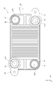
- FIG. 1 is a front view showing the front structure of the heat exchanger of the first embodiment.
- FIG. 2 is a plan view showing a plan structure of the heat exchanger of the first embodiment.
- FIG. 3 is a cross-sectional view showing a cross-sectional structure taken along the line III-III of FIG.
- FIG. 4 is a cross-sectional view showing a cross-sectional structure of the heat exchanger of the second embodiment.
- the heat exchanger 10 of the first embodiment shown in FIGS. 1 to 3 will be described.
- the heat exchanger 10 can be used as an evaporator that evaporates the refrigerant by exchanging heat between the refrigerant circulating in the refrigeration cycle of the air conditioner mounted on the vehicle and the cooling water, for example.
- the cooling water corresponds to a fluid that exchanges heat with the refrigerant.
- the heat exchanger 10 includes a heat exchange core unit 20, a refrigerant inflow unit 30, a refrigerant discharge unit 31, a cooling water inflow unit 40, and a cooling water discharge unit 41. ..
- the heat exchange core portion 20 is composed of a plurality of plate members 21 stacked and arranged in the Z-axis direction.
- the Z-axis direction is also referred to as “plate stacking direction Z”.
- one of the plate stacking directions Z is referred to as "Z1 direction”
- the other direction is referred to as "Z2 direction”.
- a refrigerant flow path through which the refrigerant flows and a cooling water flow path through which the cooling water flows are provided inside each plate member 21, Refrigerant flow paths and cooling water flow paths are alternately arranged in the heat exchanger 10.
- the heat exchange core portion 20 has a substantially rectangular cross-sectional shape orthogonal to the plate stacking direction Z.
- the longitudinal direction and the lateral direction of the heat exchange core portion 20 are referred to as "X-axis direction” and "Y-axis direction", respectively.
- the refrigerant inflow portion 30 and the refrigerant discharge portion are located at the two corners located diagonally at the four corners of the outermost shell plate member 21a arranged at the most end in the Z1 direction. 31 are provided respectively.
- a cooling water inflow portion 40 and a cooling water discharge portion 41 are provided at the remaining corner portions located diagonally.
- a first refrigerant tank portion 61 is formed inside the heat exchange core portion 20 so as to extend in the Z2 direction from the refrigerant inflow portion 30, and the refrigerant discharge portion 31
- the second refrigerant tank portion 62 is formed so as to extend in the Z2 direction.
- the first refrigerant tank portion 61 is formed in a tubular shape about the axis m11.
- the second refrigerant tank portion 62 is formed in a tubular shape about the axis m12.
- a first cooling water tank portion 71 is formed so as to extend in the Z2 direction from the cooling water inflow portion 40, and also extends in the Z2 direction from the cooling water discharge portion 41.
- a second cooling water tank portion 72 is formed.
- the first cooling water tank portion 71 is formed in a tubular shape about the axis m21.
- the second cooling water tank portion 72 is formed in a tubular shape about the axis m22.
- Each tank portion 61, 62, 71, 72 is formed so as to penetrate a plurality of plate members 21 in the plate stacking direction Z.
- a refrigerant having a two-phase state of a gas phase and a liquid phase flows into the first refrigerant tank portion 61 from the refrigerant inflow portion 30, and cooling water flows from the cooling water inflow portion 40 into the first cooling water. It flows into the tank section 71.
- the refrigerant that has flowed into the first refrigerant tank portion 61 is distributed to the plurality of refrigerant flow paths of the heat exchange core portion 20.
- the refrigerant that has flowed through each of the plurality of refrigerant channels is collected in the second refrigerant tank portion 62 and then discharged from the refrigerant discharge portion 31.
- the cooling water that has flowed into the first cooling water tank portion 71 is distributed to the plurality of cooling water flow paths of the heat exchange core portion 20.
- the cooling water that has flowed through each of the plurality of cooling water channels is collected in the second cooling water tank portion 72 and then discharged from the cooling water discharge portion 41.
- heat exchanger 10 heat exchange is performed between the refrigerant flowing through the refrigerant flow path and the cooling water flowing through the cooling water flow path, so that the refrigerant is heated and evaporated.
- the heat exchange core portion 20 includes a plate member 21, a refrigerant fin F10, and a cooling water fin F20. These members are made of a metal material such as an aluminum alloy.
- the plate member 21 is composed of an outer plate 22 and an inner plate 23.
- the outer plate 22 is made of a plate-shaped member having a substantially rectangular cross-sectional shape orthogonal to the plate stacking direction Z.
- An overhanging portion 220 projecting in the Z1 direction is formed on the outer peripheral edge portion of the outer plate 22.
- the plurality of outer plates 22 are arranged in a laminated manner so that the overhanging portion 220 faces the Z1 direction.
- the overhanging portions 220 of each outer plate 22 are joined to each other by brazing.
- the outer plate 22 is provided with a burring portion 221 formed by burring.
- the burring portion 221 is a portion formed so as to project in a tubular shape in the Z1 direction about the axis m11, which is the central axis of the first refrigerant tank portion 61.
- a protruding portion 222 protruding in the Z2 direction is formed in a portion of the outer plate 22 corresponding to the base end portion of the burring portion 221.
- the inner plate 23 is also made of a plate-shaped member having a substantially rectangular cross-sectional shape orthogonal to the plate stacking direction Z.
- the inner plate 23 is arranged inside the overhanging portion 220 of the outer plate 22 and between the adjacent outer plates 22 and 22.
- the outer peripheral edge portion of the inner plate 23 is joined to the inner peripheral portion of the overhanging portion 220 of the outer plate 22 by brazing.
- the inner plate 23 divides the space formed between the adjacent outer plates 22 and 22 into independent refrigerant flow paths W10 and cooling water flow paths W20 that are not communicated with each other. More specifically, the gap formed between the inner plate 23 and the outer plate 22 adjacent to the inner plate 23 in the Z2 direction constitutes the refrigerant flow path W10.
- a gap formed between the inner plate 23 and the outer plate 22 adjacent to the inner plate 23 in the Z1 direction constitutes the cooling water flow path W20.
- the refrigerant flow path W10 corresponds to the first flow path
- the cooling water flow path W20 corresponds to the second flow path.
- Refrigerant fins F10 are arranged in the refrigerant flow path W10.
- the portion of the refrigerant flow path W10 where the refrigerant fins F10 are arranged is referred to as a “fin installation portion 80”.
- the cooling water fins F20 are arranged in the cooling water flow path W20.
- an offset fin can be used as the refrigerant fin F10 and the cooling water fin F20.
- the refrigerant fin F10 increases the heat transfer area for the refrigerant flowing through the refrigerant flow path W10.
- the cooling water fin F20 increases the heat transfer area for the cooling water flowing through the cooling water flow path W20.
- the inner plate 23 is provided with a burring portion 231 formed by burring in a portion corresponding to the burring portion 221 of the outer plate 22.
- the burring portion 231 is a portion formed so as to project in a tubular shape in the Z2 direction about the axis m11, which is the central axis of the first refrigerant tank portion 61.
- a protruding portion 232 protruding in the Z2 direction is formed at a portion corresponding to the base end portion of the burring portion 231.
- the protruding portion 232 of the inner plate 23 is joined to the protruding portion 222 of the outer plate 22 adjacent to each other in the Z1 direction by brazing.
- the burring portion 221 of the outer plate 22 and the burring portion 231 of the inner plate 23 form a first refrigerant tank portion 61 formed of a tubular space centered on the axis m11.
- the burring portion 221 of the outer plate 22 and the burring portion 231 of the inner plate 23 constitute the peripheral wall 610 of the first refrigerant tank portion 61.
- cooling water flow path W20 and the first refrigerant tank portion 61 are partitioned by joining the protruding portion 222 of the outer plate 22 and the protruding portion 232 of the protruding portion 232 of the inner plate 23 to each other. Therefore, the refrigerant flowing through the first refrigerant tank portion 61 does not flow into the cooling water flow path W20.
- the inflow port 611 is a portion in which the refrigerant that has flowed into the first refrigerant tank portion 61 is distributed and flows into the plurality of refrigerant flow paths W10.
- the width of the fin installation portion 80 of the refrigerant flow path W10 in the plate stacking direction Z is “H10”
- the width H20 of the inflow port 611 is narrower than the width H10 of the fin installation portion 80. .. Therefore, in the heat exchanger 10, the inflow port 611 is a flow path reducing portion 100 narrower than the width H10 of the fin installation portion 80.
- the actions and effects shown in the following (1) to (3) can be obtained.
- (1) The refrigerant that has flowed from the refrigerant inflow section 30 into the first refrigerant tank section 61 tends to flow toward the downstream side of the first refrigerant tank section 61 due to the inertia of the flow.
- the width H20 of the inflow port 611 is narrow, so that the refrigerant can be used as the refrigerant.
- a flow path reduction portion 100 narrower than the width H10 of the fin installation portion 80 is formed. According to such a configuration, the flow path reducing portion 100 can be easily formed in the heat exchanger 10.
- the flow path reducing portion 100 is formed in the burring portions 221,231 of the plate member 21. More specifically, the flow path reducing portion 100 is provided between the two burring portions 221,231 formed on the outer plate 22 and the inner plate 23, respectively. According to such a configuration, the flow path reducing portion 100 can be easily formed in the heat exchanger 10.
- the burring portion 221 of the outer plate 22 and the burring portion 231 of the inner plate 23 are joined to each other by brazing.
- the first refrigerant tank portion 61 is partitioned and formed by this joint structure. Further, due to the joint structure of the burring portions 221, 231 the refrigerant flow path W10 is communicated with the first refrigerant tank portion 61, while the cooling water flow path W20 serves as a flow path independent of the first refrigerant tank portion 61. It is formed.
- the width H20 of the inflow port 611 formed on the peripheral wall 610 of the first refrigerant tank portion 61 and the width H10 of the fin installation portion 80 of the refrigerant flow path W10 have the same length. Is set to.
- the outer plate 22 and the inner plate 23 are respectively formed with protrusions 223 and 232 so that the cross-sectional area of the flow path in the middle of the refrigerant flow path W10 from the inflow port 611 to the fin installation portion 80 is narrowed.
- the protrusions 223 and 232 constitute a flow path reduction portion 100 narrower than the width H20 of the fin installation portion 80 in the plate stacking direction Z.
- each embodiment can also be implemented in the following embodiments.
- the heat exchanger 10 of each embodiment there may be a plate member 21 in which the flow path reducing portion 100 is formed and a plate member 21 in which the flow path reducing portion 100 is not formed.
- the flow path to the plate member 21 arranged on the downstream side of the first refrigerant tank portion 61 in consideration of the fact that the refrigerant easily flows to the plate member 21 arranged on the downstream side of the first refrigerant tank portion 61.
- the reduced portion 100 it is also possible to adopt a structure in which the flow path reduced portion 100 is not formed on the plate member 21 arranged on the upstream side of the first refrigerant tank portion 61.
- the flow path reducing portion 100 formed by the burring portions 221, 231 of the plates 22 and 23 of the first embodiment and the flow path reducing portion 100 formed by the protruding portions 222 and 232 of the plates 22 and 23 are formed. It may be combined. -The heat exchanger 10 of each embodiment can also be applied to a laminated evaporator that exchanges heat between air and a refrigerant.
Abstract
Échangeur de chaleur pourvu d'ailettes (F10) disposées dans un premier trajet d'écoulement (W10) et d'une partie de réservoir cylindrique (61) formée en s'étendant à travers une pluralité d'éléments de plaque (21) dans une direction de couche de plaque, la direction de couche de plaque étant la direction dans laquelle la pluralité d'éléments de plaque sont stratifiés les uns sur les autres. Une entrée (611) est formée dans une paroi circonférentielle (610) de la partie réservoir pour permettre au fluide frigorigène de s'écouler dans le premier trajet d'écoulement. Lorsqu'une partie dans le premier trajet d'écoulement où les ailettes sont disposées est définie comme une partie d'installation d'ailette (80), une partie rétrécie de trajet d'écoulement (100) avec une largeur plus étroite que la partie d'installation d'ailette dans la direction de la couche de plaque est formée de l'entrée à la partie d'installation d'ailette.
Priority Applications (3)
| Application Number | Priority Date | Filing Date | Title |
|---|---|---|---|
| CN202080021402.3A CN113574332B (zh) | 2019-04-01 | 2020-03-25 | 热交换器 |
| DE112020001705.2T DE112020001705T5 (de) | 2019-04-01 | 2020-03-25 | Wärmetauscher |
| US17/487,905 US20220018614A1 (en) | 2019-04-01 | 2021-09-28 | Heat exchanger |
Applications Claiming Priority (2)
| Application Number | Priority Date | Filing Date | Title |
|---|---|---|---|
| JP2019070170A JP7247717B2 (ja) | 2019-04-01 | 2019-04-01 | 熱交換器 |
| JP2019-070170 | 2019-04-01 |
Related Child Applications (1)
| Application Number | Title | Priority Date | Filing Date |
|---|---|---|---|
| US17/487,905 Continuation US20220018614A1 (en) | 2019-04-01 | 2021-09-28 | Heat exchanger |
Publications (1)
| Publication Number | Publication Date |
|---|---|
| WO2020203555A1 true WO2020203555A1 (fr) | 2020-10-08 |
Family
ID=72668278
Family Applications (1)
| Application Number | Title | Priority Date | Filing Date |
|---|---|---|---|
| PCT/JP2020/013344 WO2020203555A1 (fr) | 2019-04-01 | 2020-03-25 | Échangeur de chaleur |
Country Status (5)
| Country | Link |
|---|---|
| US (1) | US20220018614A1 (fr) |
| JP (1) | JP7247717B2 (fr) |
| CN (1) | CN113574332B (fr) |
| DE (1) | DE112020001705T5 (fr) |
| WO (1) | WO2020203555A1 (fr) |
Cited By (1)
| Publication number | Priority date | Publication date | Assignee | Title |
|---|---|---|---|---|
| SE2150186A1 (en) * | 2021-02-22 | 2022-08-23 | Swep Int Ab | A brazed plate heat exchanger |
Citations (6)
| Publication number | Priority date | Publication date | Assignee | Title |
|---|---|---|---|---|
| US4370868A (en) * | 1981-01-05 | 1983-02-01 | Borg-Warner Corporation | Distributor for plate fin evaporator |
| JPH05196321A (ja) * | 1991-01-31 | 1993-08-06 | Nippondenso Co Ltd | 蒸発器および冷凍サイクル装置 |
| JP2005527777A (ja) * | 2002-05-29 | 2005-09-15 | アルファ ラヴァル コーポレイト アクチボラゲット | プレート熱交換器装置および伝熱板 |
| JP2008536090A (ja) * | 2005-04-13 | 2008-09-04 | アルファ ラヴァル コーポレイト アクチボラゲット | プレート熱交換器 |
| JP2015059669A (ja) * | 2013-09-17 | 2015-03-30 | 株式会社デンソー | 積層型熱交換器 |
| US20190033005A1 (en) * | 2016-04-06 | 2019-01-31 | Alfa Laval Corporate Ab | Heat exchanger plate, a plate heat exchanger, and a method of making a plate heat exchanger |
Family Cites Families (20)
| Publication number | Priority date | Publication date | Assignee | Title |
|---|---|---|---|---|
| DE19939264B4 (de) * | 1999-08-19 | 2005-08-18 | Behr Gmbh & Co. Kg | Plattenwärmeübertrager |
| JP2002303499A (ja) * | 2001-03-30 | 2002-10-18 | Hisaka Works Ltd | プレート式熱交換器 |
| JP2003269883A (ja) * | 2002-03-14 | 2003-09-25 | Showa Denko Kk | 積層型熱交換器及びこれによって構成される積層型蒸発器並びにこれを備えた冷凍サイクルシステム |
| JP2005003277A (ja) * | 2003-06-12 | 2005-01-06 | Calsonic Kansei Corp | 熱交換器 |
| US7107680B2 (en) * | 2003-06-20 | 2006-09-19 | Denso Corporation | Manufacturing method of heat exchanger and structure thereof |
| SE526409C2 (sv) * | 2004-01-09 | 2005-09-06 | Alfa Laval Corp Ab | Plattvärmeväxlare |
| CN101443621A (zh) * | 2005-02-02 | 2009-05-27 | 开利公司 | 具有皱缩通道进口的并流式热交换器 |
| CN102042772B (zh) * | 2010-05-14 | 2013-03-06 | 南京工业大学 | 具有介质均分器的层叠板翅结构换热器 |
| JP5510106B2 (ja) * | 2010-06-21 | 2014-06-04 | 株式会社デンソー | 排気熱交換装置 |
| DE102010050894A1 (de) * | 2010-11-10 | 2012-05-10 | Valeo Klimasysteme Gmbh | Plattenwärmetauscher und Klimakreislauf für ein Fahrzeug |
| DE102011081886A1 (de) * | 2011-08-31 | 2013-02-28 | Behr Gmbh & Co. Kg | Wärmeübertrager |
| JP6094261B2 (ja) * | 2013-02-27 | 2017-03-15 | 株式会社デンソー | 積層型熱交換器 |
| JP6711841B2 (ja) * | 2015-10-29 | 2020-06-17 | 株式会社ティラド | ヘッダプレートレス型熱交換器コアの構造 |
| EP3388772B1 (fr) * | 2015-12-11 | 2020-11-04 | Mitsubishi Electric Corporation | Échangeur de chaleur à plaques et dispositif à cycle frigorifique |
| JP6578964B2 (ja) * | 2016-01-26 | 2019-09-25 | 株式会社デンソー | 積層型熱交換器 |
| WO2017201252A1 (fr) * | 2016-05-20 | 2017-11-23 | Modine Manufacturing Company | Échangeur de chaleur et système d'échange de chaleur |
| US11231210B2 (en) * | 2016-06-07 | 2022-01-25 | Denso Corporation | Stack type heat exchanger |
| DE102017211529A1 (de) * | 2017-07-06 | 2019-01-10 | Mahle International Gmbh | Einsatzrohr für den Eintrittskanal eines Plattenwärmetauschers |
| JP2019070170A (ja) | 2017-10-05 | 2019-05-09 | Jx金属株式会社 | 銅の分離方法および銅の回収方法 |
| CN112997045B (zh) * | 2018-11-16 | 2022-12-20 | 三菱电机株式会社 | 板式热交换器、热泵装置及热泵式制冷制热热水供给系统 |
-
2019
- 2019-04-01 JP JP2019070170A patent/JP7247717B2/ja active Active
-
2020
- 2020-03-25 CN CN202080021402.3A patent/CN113574332B/zh active Active
- 2020-03-25 WO PCT/JP2020/013344 patent/WO2020203555A1/fr active Application Filing
- 2020-03-25 DE DE112020001705.2T patent/DE112020001705T5/de active Pending
-
2021
- 2021-09-28 US US17/487,905 patent/US20220018614A1/en active Pending
Patent Citations (6)
| Publication number | Priority date | Publication date | Assignee | Title |
|---|---|---|---|---|
| US4370868A (en) * | 1981-01-05 | 1983-02-01 | Borg-Warner Corporation | Distributor for plate fin evaporator |
| JPH05196321A (ja) * | 1991-01-31 | 1993-08-06 | Nippondenso Co Ltd | 蒸発器および冷凍サイクル装置 |
| JP2005527777A (ja) * | 2002-05-29 | 2005-09-15 | アルファ ラヴァル コーポレイト アクチボラゲット | プレート熱交換器装置および伝熱板 |
| JP2008536090A (ja) * | 2005-04-13 | 2008-09-04 | アルファ ラヴァル コーポレイト アクチボラゲット | プレート熱交換器 |
| JP2015059669A (ja) * | 2013-09-17 | 2015-03-30 | 株式会社デンソー | 積層型熱交換器 |
| US20190033005A1 (en) * | 2016-04-06 | 2019-01-31 | Alfa Laval Corporate Ab | Heat exchanger plate, a plate heat exchanger, and a method of making a plate heat exchanger |
Cited By (1)
| Publication number | Priority date | Publication date | Assignee | Title |
|---|---|---|---|---|
| SE2150186A1 (en) * | 2021-02-22 | 2022-08-23 | Swep Int Ab | A brazed plate heat exchanger |
Also Published As
| Publication number | Publication date |
|---|---|
| JP7247717B2 (ja) | 2023-03-29 |
| CN113574332B (zh) | 2023-04-07 |
| US20220018614A1 (en) | 2022-01-20 |
| JP2020169745A (ja) | 2020-10-15 |
| DE112020001705T5 (de) | 2021-12-16 |
| CN113574332A (zh) | 2021-10-29 |
Similar Documents
| Publication | Publication Date | Title |
|---|---|---|
| JP6567097B2 (ja) | プレート式熱交換器、およびそれを備えたヒートポンプ式暖房給湯システム | |
| JP2007278556A (ja) | 熱交換器 | |
| JP2007298260A (ja) | 熱交換器 | |
| JP2005214511A (ja) | 熱交換器 | |
| US7121331B2 (en) | Heat exchanger | |
| JP2004037073A (ja) | 積層型熱交換器 | |
| WO2020203555A1 (fr) | Échangeur de chaleur | |
| JP2020079693A (ja) | 熱交換器 | |
| JP2015203508A (ja) | プレート式熱交換器 | |
| WO2021025151A1 (fr) | Échangeur de chaleur | |
| WO2020184315A1 (fr) | Échangeur de chaleur | |
| JPH0894274A (ja) | 積層型熱交換器 | |
| JP2019200039A (ja) | プレート積層型の熱交換器 | |
| JPH02106697A (ja) | 積層形熱交換器 | |
| JP2009299923A (ja) | 熱交換器 | |
| WO2019216183A1 (fr) | Échangeur de chaleur de type à plaques stratifiées | |
| JP2006349275A (ja) | 熱交換器 | |
| JP7226364B2 (ja) | 熱交換器 | |
| WO2021149462A1 (fr) | Échangeur de chaleur | |
| WO2021039302A1 (fr) | Échangeur de chaleur | |
| JP7164291B2 (ja) | 冷蔵庫 | |
| WO2020149107A1 (fr) | Échangeur de chaleur | |
| JP2005283020A (ja) | 熱交換器 | |
| JP2018096568A (ja) | 熱交換器 | |
| JP2008039212A (ja) | 熱交換器 |
Legal Events
| Date | Code | Title | Description |
|---|---|---|---|
| 121 | Ep: the epo has been informed by wipo that ep was designated in this application |
Ref document number: 20781971 Country of ref document: EP Kind code of ref document: A1 |
|
| 122 | Ep: pct application non-entry in european phase |
Ref document number: 20781971 Country of ref document: EP Kind code of ref document: A1 |