WO2020203555A1 - 熱交換器 - Google Patents
熱交換器 Download PDFInfo
- Publication number
- WO2020203555A1 WO2020203555A1 PCT/JP2020/013344 JP2020013344W WO2020203555A1 WO 2020203555 A1 WO2020203555 A1 WO 2020203555A1 JP 2020013344 W JP2020013344 W JP 2020013344W WO 2020203555 A1 WO2020203555 A1 WO 2020203555A1
- Authority
- WO
- WIPO (PCT)
- Prior art keywords
- flow path
- refrigerant
- heat exchanger
- plate
- flow
- Prior art date
Links
Images


Classifications
-
- F—MECHANICAL ENGINEERING; LIGHTING; HEATING; WEAPONS; BLASTING
- F28—HEAT EXCHANGE IN GENERAL
- F28D—HEAT-EXCHANGE APPARATUS, NOT PROVIDED FOR IN ANOTHER SUBCLASS, IN WHICH THE HEAT-EXCHANGE MEDIA DO NOT COME INTO DIRECT CONTACT
- F28D9/00—Heat-exchange apparatus having stationary plate-like or laminated conduit assemblies for both heat-exchange media, the media being in contact with different sides of a conduit wall
- F28D9/0031—Heat-exchange apparatus having stationary plate-like or laminated conduit assemblies for both heat-exchange media, the media being in contact with different sides of a conduit wall the conduits for one heat-exchange medium being formed by paired plates touching each other
- F28D9/0043—Heat-exchange apparatus having stationary plate-like or laminated conduit assemblies for both heat-exchange media, the media being in contact with different sides of a conduit wall the conduits for one heat-exchange medium being formed by paired plates touching each other the plates having openings therein for circulation of at least one heat-exchange medium from one conduit to another
- F28D9/005—Heat-exchange apparatus having stationary plate-like or laminated conduit assemblies for both heat-exchange media, the media being in contact with different sides of a conduit wall the conduits for one heat-exchange medium being formed by paired plates touching each other the plates having openings therein for circulation of at least one heat-exchange medium from one conduit to another the plates having openings therein for both heat-exchange media
-
- B—PERFORMING OPERATIONS; TRANSPORTING
- B60—VEHICLES IN GENERAL
- B60H—ARRANGEMENTS OF HEATING, COOLING, VENTILATING OR OTHER AIR-TREATING DEVICES SPECIALLY ADAPTED FOR PASSENGER OR GOODS SPACES OF VEHICLES
- B60H1/00—Heating, cooling or ventilating [HVAC] devices
- B60H1/32—Cooling devices
-
- F—MECHANICAL ENGINEERING; LIGHTING; HEATING; WEAPONS; BLASTING
- F25—REFRIGERATION OR COOLING; COMBINED HEATING AND REFRIGERATION SYSTEMS; HEAT PUMP SYSTEMS; MANUFACTURE OR STORAGE OF ICE; LIQUEFACTION SOLIDIFICATION OF GASES
- F25B—REFRIGERATION MACHINES, PLANTS OR SYSTEMS; COMBINED HEATING AND REFRIGERATION SYSTEMS; HEAT PUMP SYSTEMS
- F25B39/00—Evaporators; Condensers
- F25B39/02—Evaporators
-
- F—MECHANICAL ENGINEERING; LIGHTING; HEATING; WEAPONS; BLASTING
- F28—HEAT EXCHANGE IN GENERAL
- F28F—DETAILS OF HEAT-EXCHANGE AND HEAT-TRANSFER APPARATUS, OF GENERAL APPLICATION
- F28F3/00—Plate-like or laminated elements; Assemblies of plate-like or laminated elements
- F28F3/08—Elements constructed for building-up into stacks, e.g. capable of being taken apart for cleaning
-
- F—MECHANICAL ENGINEERING; LIGHTING; HEATING; WEAPONS; BLASTING
- F28—HEAT EXCHANGE IN GENERAL
- F28F—DETAILS OF HEAT-EXCHANGE AND HEAT-TRANSFER APPARATUS, OF GENERAL APPLICATION
- F28F9/00—Casings; Header boxes; Auxiliary supports for elements; Auxiliary members within casings
- F28F9/02—Header boxes; End plates
- F28F9/026—Header boxes; End plates with static flow control means, e.g. with means for uniformly distributing heat exchange media into conduits
- F28F9/0282—Header boxes; End plates with static flow control means, e.g. with means for uniformly distributing heat exchange media into conduits by varying the geometry of conduit ends, e.g. by using inserts or attachments for modifying the pattern of flow at the conduit inlet or outlet
-
- F—MECHANICAL ENGINEERING; LIGHTING; HEATING; WEAPONS; BLASTING
- F28—HEAT EXCHANGE IN GENERAL
- F28D—HEAT-EXCHANGE APPARATUS, NOT PROVIDED FOR IN ANOTHER SUBCLASS, IN WHICH THE HEAT-EXCHANGE MEDIA DO NOT COME INTO DIRECT CONTACT
- F28D21/00—Heat-exchange apparatus not covered by any of the groups F28D1/00 - F28D20/00
- F28D2021/0019—Other heat exchangers for particular applications; Heat exchange systems not otherwise provided for
- F28D2021/0068—Other heat exchangers for particular applications; Heat exchange systems not otherwise provided for for refrigerant cycles
- F28D2021/0071—Evaporators
-
- F—MECHANICAL ENGINEERING; LIGHTING; HEATING; WEAPONS; BLASTING
- F28—HEAT EXCHANGE IN GENERAL
- F28D—HEAT-EXCHANGE APPARATUS, NOT PROVIDED FOR IN ANOTHER SUBCLASS, IN WHICH THE HEAT-EXCHANGE MEDIA DO NOT COME INTO DIRECT CONTACT
- F28D21/00—Heat-exchange apparatus not covered by any of the groups F28D1/00 - F28D20/00
- F28D2021/0019—Other heat exchangers for particular applications; Heat exchange systems not otherwise provided for
- F28D2021/008—Other heat exchangers for particular applications; Heat exchange systems not otherwise provided for for vehicles
- F28D2021/0085—Evaporators
-
- F—MECHANICAL ENGINEERING; LIGHTING; HEATING; WEAPONS; BLASTING
- F28—HEAT EXCHANGE IN GENERAL
- F28F—DETAILS OF HEAT-EXCHANGE AND HEAT-TRANSFER APPARATUS, OF GENERAL APPLICATION
- F28F2275/00—Fastening; Joining
- F28F2275/04—Fastening; Joining by brazing
-
- F—MECHANICAL ENGINEERING; LIGHTING; HEATING; WEAPONS; BLASTING
- F28—HEAT EXCHANGE IN GENERAL
- F28F—DETAILS OF HEAT-EXCHANGE AND HEAT-TRANSFER APPARATUS, OF GENERAL APPLICATION
- F28F3/00—Plate-like or laminated elements; Assemblies of plate-like or laminated elements
- F28F3/02—Elements or assemblies thereof with means for increasing heat-transfer area, e.g. with fins, with recesses, with corrugations
- F28F3/025—Elements or assemblies thereof with means for increasing heat-transfer area, e.g. with fins, with recesses, with corrugations the means being corrugated, plate-like elements
- F28F3/027—Elements or assemblies thereof with means for increasing heat-transfer area, e.g. with fins, with recesses, with corrugations the means being corrugated, plate-like elements with openings, e.g. louvered corrugated fins; Assemblies of corrugated strips
-
- F—MECHANICAL ENGINEERING; LIGHTING; HEATING; WEAPONS; BLASTING
- F28—HEAT EXCHANGE IN GENERAL
- F28F—DETAILS OF HEAT-EXCHANGE AND HEAT-TRANSFER APPARATUS, OF GENERAL APPLICATION
- F28F3/00—Plate-like or laminated elements; Assemblies of plate-like or laminated elements
- F28F3/02—Elements or assemblies thereof with means for increasing heat-transfer area, e.g. with fins, with recesses, with corrugations
- F28F3/06—Elements or assemblies thereof with means for increasing heat-transfer area, e.g. with fins, with recesses, with corrugations the means being attachable to the element
Definitions
- This disclosure relates to heat exchangers.
- the heat exchanger described in Patent Document 1 has a structure in which a plurality of plate members are laminated. A refrigerant flow path through which the refrigerant flows and a cooling water flow path through which the cooling water flows are formed between the plurality of plate members.
- the laminated structure of the plate members is formed with a refrigerant tank portion that distributes the refrigerant flowing from the inflow port to a plurality of refrigerant flow paths, or collects the refrigerant flowing through the plurality of refrigerant flow paths and discharges the refrigerant from the discharge port. ing.
- the cooling water flowing from the inflow port is distributed to a plurality of cooling water flow paths, and the cooling water flowing through the plurality of cooling water flow paths is collected and discharged from the discharge port.
- the tank part is also formed. In this heat exchanger, heat exchange is performed between the refrigerant flowing through the refrigerant flow path and the cooling water flowing through the cooling water flow path.
- the refrigerant flowing into the refrigerant tank portion from the inflow port may be in a two-phase state in which a gas phase refrigerant and a liquid phase refrigerant are mixed.
- the liquid-phase refrigerant tends to flow toward the downstream side of the refrigerant tank portion due to the inertia of the flow. Therefore, among the plurality of refrigerant flow paths, the liquid-phase refrigerant tends to flow in the refrigerant flow path arranged near the downstream side of the refrigerant tank portion. If the flow rate distribution of the refrigerant in the plurality of refrigerant flow paths is biased in this way, the heat exchange performance of the heat exchanger may be significantly deteriorated.
- An object of the present disclosure is to provide a heat exchanger capable of improving the distributability of a refrigerant.
- the heat exchanger has a plurality of plate members arranged in a laminated manner, and a plurality of first flow paths and a plurality of second flow paths are formed by the plurality of plate members, and the first flow. Heat exchange takes place between the refrigerant flowing through the path and the fluid flowing through the second flow path.
- the heat exchanger penetrates the fins arranged in the first flow path and the plurality of plate members in the plate stacking direction. It includes a tubular tank portion to be formed. An inflow port for flowing the refrigerant into the first flow path is formed on the peripheral wall of the tank portion.
- a flow path reduction portion narrower than the width of the fin installation portion in the plate stacking direction is formed between the inflow port and the fin installation portion. ing.
- the heat exchanger has a plurality of plate members arranged in a laminated manner, and a plurality of first flow paths and a plurality of second flow paths are formed by the plurality of plate members.
- a heat exchanger in which heat exchange is performed between the refrigerant flowing through the first flow path and the fluid flowing through the second flow path, and the direction in which a plurality of plate members are stacked and arranged is defined as the plate stacking direction.
- a tubular tank portion formed so as to penetrate a plurality of plate members in the plate stacking direction is provided.
- An inflow port for flowing the refrigerant into the first flow path is formed on the peripheral wall of the tank portion.
- a flow path reduction portion is formed between the first flow path and the inflow port so that the flow path cross-sectional area becomes narrow.
- the flow path reduction portion is formed between the inflow port and the fin installation portion or between the first flow path and the inflow port, the refrigerant flows from the tank portion to the first flow path. It becomes difficult to flow in. That is, it is possible to increase the water flow resistance of the refrigerant flowing from the tank portion into the first flow path. As a result, even if the flow rate distribution of the refrigerant is biased in the tank portion due to the inertia of the flow of the refrigerant, the refrigerant flows from the portion where the flow rate of the refrigerant tends to increase to the portion where the flow rate of the refrigerant tends to decrease. As a result, the distributability of the refrigerant can be improved.
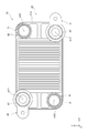
- FIG. 1 is a front view showing the front structure of the heat exchanger of the first embodiment.
- FIG. 2 is a plan view showing a plan structure of the heat exchanger of the first embodiment.
- FIG. 3 is a cross-sectional view showing a cross-sectional structure taken along the line III-III of FIG.
- FIG. 4 is a cross-sectional view showing a cross-sectional structure of the heat exchanger of the second embodiment.
- the heat exchanger 10 of the first embodiment shown in FIGS. 1 to 3 will be described.
- the heat exchanger 10 can be used as an evaporator that evaporates the refrigerant by exchanging heat between the refrigerant circulating in the refrigeration cycle of the air conditioner mounted on the vehicle and the cooling water, for example.
- the cooling water corresponds to a fluid that exchanges heat with the refrigerant.
- the heat exchanger 10 includes a heat exchange core unit 20, a refrigerant inflow unit 30, a refrigerant discharge unit 31, a cooling water inflow unit 40, and a cooling water discharge unit 41. ..
- the heat exchange core portion 20 is composed of a plurality of plate members 21 stacked and arranged in the Z-axis direction.
- the Z-axis direction is also referred to as “plate stacking direction Z”.
- one of the plate stacking directions Z is referred to as "Z1 direction”
- the other direction is referred to as "Z2 direction”.
- a refrigerant flow path through which the refrigerant flows and a cooling water flow path through which the cooling water flows are provided inside each plate member 21, Refrigerant flow paths and cooling water flow paths are alternately arranged in the heat exchanger 10.
- the heat exchange core portion 20 has a substantially rectangular cross-sectional shape orthogonal to the plate stacking direction Z.
- the longitudinal direction and the lateral direction of the heat exchange core portion 20 are referred to as "X-axis direction” and "Y-axis direction", respectively.
- the refrigerant inflow portion 30 and the refrigerant discharge portion are located at the two corners located diagonally at the four corners of the outermost shell plate member 21a arranged at the most end in the Z1 direction. 31 are provided respectively.
- a cooling water inflow portion 40 and a cooling water discharge portion 41 are provided at the remaining corner portions located diagonally.
- a first refrigerant tank portion 61 is formed inside the heat exchange core portion 20 so as to extend in the Z2 direction from the refrigerant inflow portion 30, and the refrigerant discharge portion 31
- the second refrigerant tank portion 62 is formed so as to extend in the Z2 direction.
- the first refrigerant tank portion 61 is formed in a tubular shape about the axis m11.
- the second refrigerant tank portion 62 is formed in a tubular shape about the axis m12.
- a first cooling water tank portion 71 is formed so as to extend in the Z2 direction from the cooling water inflow portion 40, and also extends in the Z2 direction from the cooling water discharge portion 41.
- a second cooling water tank portion 72 is formed.
- the first cooling water tank portion 71 is formed in a tubular shape about the axis m21.
- the second cooling water tank portion 72 is formed in a tubular shape about the axis m22.
- Each tank portion 61, 62, 71, 72 is formed so as to penetrate a plurality of plate members 21 in the plate stacking direction Z.
- a refrigerant having a two-phase state of a gas phase and a liquid phase flows into the first refrigerant tank portion 61 from the refrigerant inflow portion 30, and cooling water flows from the cooling water inflow portion 40 into the first cooling water. It flows into the tank section 71.
- the refrigerant that has flowed into the first refrigerant tank portion 61 is distributed to the plurality of refrigerant flow paths of the heat exchange core portion 20.
- the refrigerant that has flowed through each of the plurality of refrigerant channels is collected in the second refrigerant tank portion 62 and then discharged from the refrigerant discharge portion 31.
- the cooling water that has flowed into the first cooling water tank portion 71 is distributed to the plurality of cooling water flow paths of the heat exchange core portion 20.
- the cooling water that has flowed through each of the plurality of cooling water channels is collected in the second cooling water tank portion 72 and then discharged from the cooling water discharge portion 41.
- heat exchanger 10 heat exchange is performed between the refrigerant flowing through the refrigerant flow path and the cooling water flowing through the cooling water flow path, so that the refrigerant is heated and evaporated.
- the heat exchange core portion 20 includes a plate member 21, a refrigerant fin F10, and a cooling water fin F20. These members are made of a metal material such as an aluminum alloy.
- the plate member 21 is composed of an outer plate 22 and an inner plate 23.
- the outer plate 22 is made of a plate-shaped member having a substantially rectangular cross-sectional shape orthogonal to the plate stacking direction Z.
- An overhanging portion 220 projecting in the Z1 direction is formed on the outer peripheral edge portion of the outer plate 22.
- the plurality of outer plates 22 are arranged in a laminated manner so that the overhanging portion 220 faces the Z1 direction.
- the overhanging portions 220 of each outer plate 22 are joined to each other by brazing.
- the outer plate 22 is provided with a burring portion 221 formed by burring.
- the burring portion 221 is a portion formed so as to project in a tubular shape in the Z1 direction about the axis m11, which is the central axis of the first refrigerant tank portion 61.
- a protruding portion 222 protruding in the Z2 direction is formed in a portion of the outer plate 22 corresponding to the base end portion of the burring portion 221.
- the inner plate 23 is also made of a plate-shaped member having a substantially rectangular cross-sectional shape orthogonal to the plate stacking direction Z.
- the inner plate 23 is arranged inside the overhanging portion 220 of the outer plate 22 and between the adjacent outer plates 22 and 22.
- the outer peripheral edge portion of the inner plate 23 is joined to the inner peripheral portion of the overhanging portion 220 of the outer plate 22 by brazing.
- the inner plate 23 divides the space formed between the adjacent outer plates 22 and 22 into independent refrigerant flow paths W10 and cooling water flow paths W20 that are not communicated with each other. More specifically, the gap formed between the inner plate 23 and the outer plate 22 adjacent to the inner plate 23 in the Z2 direction constitutes the refrigerant flow path W10.
- a gap formed between the inner plate 23 and the outer plate 22 adjacent to the inner plate 23 in the Z1 direction constitutes the cooling water flow path W20.
- the refrigerant flow path W10 corresponds to the first flow path
- the cooling water flow path W20 corresponds to the second flow path.
- Refrigerant fins F10 are arranged in the refrigerant flow path W10.
- the portion of the refrigerant flow path W10 where the refrigerant fins F10 are arranged is referred to as a “fin installation portion 80”.
- the cooling water fins F20 are arranged in the cooling water flow path W20.
- an offset fin can be used as the refrigerant fin F10 and the cooling water fin F20.
- the refrigerant fin F10 increases the heat transfer area for the refrigerant flowing through the refrigerant flow path W10.
- the cooling water fin F20 increases the heat transfer area for the cooling water flowing through the cooling water flow path W20.
- the inner plate 23 is provided with a burring portion 231 formed by burring in a portion corresponding to the burring portion 221 of the outer plate 22.
- the burring portion 231 is a portion formed so as to project in a tubular shape in the Z2 direction about the axis m11, which is the central axis of the first refrigerant tank portion 61.
- a protruding portion 232 protruding in the Z2 direction is formed at a portion corresponding to the base end portion of the burring portion 231.
- the protruding portion 232 of the inner plate 23 is joined to the protruding portion 222 of the outer plate 22 adjacent to each other in the Z1 direction by brazing.
- the burring portion 221 of the outer plate 22 and the burring portion 231 of the inner plate 23 form a first refrigerant tank portion 61 formed of a tubular space centered on the axis m11.
- the burring portion 221 of the outer plate 22 and the burring portion 231 of the inner plate 23 constitute the peripheral wall 610 of the first refrigerant tank portion 61.
- cooling water flow path W20 and the first refrigerant tank portion 61 are partitioned by joining the protruding portion 222 of the outer plate 22 and the protruding portion 232 of the protruding portion 232 of the inner plate 23 to each other. Therefore, the refrigerant flowing through the first refrigerant tank portion 61 does not flow into the cooling water flow path W20.
- the inflow port 611 is a portion in which the refrigerant that has flowed into the first refrigerant tank portion 61 is distributed and flows into the plurality of refrigerant flow paths W10.
- the width of the fin installation portion 80 of the refrigerant flow path W10 in the plate stacking direction Z is “H10”
- the width H20 of the inflow port 611 is narrower than the width H10 of the fin installation portion 80. .. Therefore, in the heat exchanger 10, the inflow port 611 is a flow path reducing portion 100 narrower than the width H10 of the fin installation portion 80.
- the actions and effects shown in the following (1) to (3) can be obtained.
- (1) The refrigerant that has flowed from the refrigerant inflow section 30 into the first refrigerant tank section 61 tends to flow toward the downstream side of the first refrigerant tank section 61 due to the inertia of the flow.
- the width H20 of the inflow port 611 is narrow, so that the refrigerant can be used as the refrigerant.
- a flow path reduction portion 100 narrower than the width H10 of the fin installation portion 80 is formed. According to such a configuration, the flow path reducing portion 100 can be easily formed in the heat exchanger 10.
- the flow path reducing portion 100 is formed in the burring portions 221,231 of the plate member 21. More specifically, the flow path reducing portion 100 is provided between the two burring portions 221,231 formed on the outer plate 22 and the inner plate 23, respectively. According to such a configuration, the flow path reducing portion 100 can be easily formed in the heat exchanger 10.
- the burring portion 221 of the outer plate 22 and the burring portion 231 of the inner plate 23 are joined to each other by brazing.
- the first refrigerant tank portion 61 is partitioned and formed by this joint structure. Further, due to the joint structure of the burring portions 221, 231 the refrigerant flow path W10 is communicated with the first refrigerant tank portion 61, while the cooling water flow path W20 serves as a flow path independent of the first refrigerant tank portion 61. It is formed.
- the width H20 of the inflow port 611 formed on the peripheral wall 610 of the first refrigerant tank portion 61 and the width H10 of the fin installation portion 80 of the refrigerant flow path W10 have the same length. Is set to.
- the outer plate 22 and the inner plate 23 are respectively formed with protrusions 223 and 232 so that the cross-sectional area of the flow path in the middle of the refrigerant flow path W10 from the inflow port 611 to the fin installation portion 80 is narrowed.
- the protrusions 223 and 232 constitute a flow path reduction portion 100 narrower than the width H20 of the fin installation portion 80 in the plate stacking direction Z.
- each embodiment can also be implemented in the following embodiments.
- the heat exchanger 10 of each embodiment there may be a plate member 21 in which the flow path reducing portion 100 is formed and a plate member 21 in which the flow path reducing portion 100 is not formed.
- the flow path to the plate member 21 arranged on the downstream side of the first refrigerant tank portion 61 in consideration of the fact that the refrigerant easily flows to the plate member 21 arranged on the downstream side of the first refrigerant tank portion 61.
- the reduced portion 100 it is also possible to adopt a structure in which the flow path reduced portion 100 is not formed on the plate member 21 arranged on the upstream side of the first refrigerant tank portion 61.
- the flow path reducing portion 100 formed by the burring portions 221, 231 of the plates 22 and 23 of the first embodiment and the flow path reducing portion 100 formed by the protruding portions 222 and 232 of the plates 22 and 23 are formed. It may be combined. -The heat exchanger 10 of each embodiment can also be applied to a laminated evaporator that exchanges heat between air and a refrigerant.
Abstract
熱交換器は、複数のプレート部材(21)が積層して配置されている方向をプレート積層方向とするとき、第1流路(W10)に配置されるフィン(F10)と、複数のプレート部材をプレート積層方向に貫通するように形成される筒状のタンク部(61)と、を備える。タンク部の周壁(610)には、第1流路に冷媒を流入させる流入口(611)が形成されている。第1流路においてフィンが配置される部分をフィン設置部(80)とするとき、流入口からフィン設置部までの間には、プレート積層方向におけるフィン設置部の幅よりも狭い流路縮小部(100)が形成されている。
Description
本出願は、2019年4月1日に出願された日本国特許出願2019-070170号に基づくものであって、その優先権の利益を主張するものであり、その特許出願の全ての内容が、参照により本明細書に組み込まれる。
本開示は、熱交換器に関する。
従来、この種の熱交換器としては、特許文献1に記載の熱交換器がある。特許文献1に記載の熱交換器は、複数のプレート部材が積層された構造を有している。複数のプレート部材の間には、冷媒の流れる冷媒流路、及び冷却水の流れる冷却水流路が形成されている。プレート部材の積層構造には、流入口から流入する冷媒を複数の冷媒流路に分配したり、複数の冷媒流路を流れる冷媒を集めて排出口から排出したりする冷媒用タンク部が形成されている。また、プレート部材の積層構造には、流入口から流入する冷却水を複数の冷却水流路に分配したり、複数の冷却水流路を流れる冷却水を集めて排出口から排出したりする冷却水用タンク部も形成されている。この熱交換器では、冷媒流路を流れる冷媒と、冷却水流路を流れる冷却水との間で熱交換が行われる。
特許文献1に記載されるような熱交換器では、流入口から冷媒用タンク部に流入する冷媒が、気相冷媒と液相冷媒とが混合した2相状態になっている場合がある。冷媒用タンク部に流入する冷媒が2相状態である場合、そのうちの液相冷媒が、その流れの慣性により、冷媒用タンク部の下流側に向かって流れ易い。そのため、複数の冷媒流路のうち、冷媒用タンク部の下流側の付近に配置される冷媒流路に液相冷媒が流れ易くなる。このようにして複数の冷媒流路における冷媒の流量分布に偏りが生じると、熱交換器の熱交換性能が著しく低下するおそれがある。
本開示の目的は、冷媒の分配性を向上させることが可能な熱交換器を提供することにある。
本開示の一態様による熱交換器は、積層して配置される複数のプレート部材を有するとともに、複数のプレート部材により複数の第1流路及び複数の第2流路が形成され、第1流路を流れる冷媒と、第2流路を流れる流体との間で熱交換が行われる。熱交換器は、複数のプレート部材が積層して配置されている方向をプレート積層方向とするとき、第1流路に配置されるフィンと、複数のプレート部材をプレート積層方向に貫通するように形成される筒状のタンク部と、を備える。タンク部の周壁には、第1流路に冷媒を流入させる流入口が形成されている。第1流路においてフィンが配置される部分をフィン設置部とするとき、流入口からフィン設置部までの間には、プレート積層方向におけるフィン設置部の幅よりも狭い流路縮小部が形成されている。
また、本開示の他の態様による熱交換器は、積層して配置される複数のプレート部材を有するとともに、複数のプレート部材により複数の第1流路及び複数の第2流路が形成され、第1流路を流れる冷媒と、第2流路を流れる流体との間で熱交換が行われる熱交換器であって、複数のプレート部材が積層して配置されている方向をプレート積層方向とするとき、複数のプレート部材をプレート積層方向に貫通するように形成される筒状のタンク部を備える。タンク部の周壁には、第1流路に冷媒を流入させる流入口が形成されている。第1流路から流入口までの間には、流路断面積が狭くなるように流路縮小部が形成されている。
これらの構成によれば、流入口からフィン設置部までの間、又は第1流路から流入口までの間に流路縮小部が形成されているため、タンク部から第1流路に冷媒が流入し難くなる。すなわち、タンク部から第1流路に流入する冷媒の通水抵抗を増加させることができる。これにより、冷媒の流れの慣性によりタンク部において冷媒の流量分布に偏りが生じた場合であっても、冷媒の流量が多くなり易い部分から、冷媒の流量が少なくなり易い部分に冷媒が流れるようになるため、結果的に冷媒の分配性を向上させることができる。
以下、熱交換器の実施形態について図面を参照しながら説明する。説明の理解を容易にするため、各図面において同一の構成要素に対しては可能な限り同一の符号を付して、重複する説明は省略する。
<第1実施形態>
はじめに、図1~図3に示される第1実施形態の熱交換器10について説明する。熱交換器10は、例えば車両に搭載される空調装置の冷凍サイクルを循環する冷媒と冷却水との間で熱交換を行うことにより冷媒を蒸発させる蒸発器として用いることができる。本実施形態では、冷却水が、冷媒と熱交換を行う流体に相当する。
<第1実施形態>
はじめに、図1~図3に示される第1実施形態の熱交換器10について説明する。熱交換器10は、例えば車両に搭載される空調装置の冷凍サイクルを循環する冷媒と冷却水との間で熱交換を行うことにより冷媒を蒸発させる蒸発器として用いることができる。本実施形態では、冷却水が、冷媒と熱交換を行う流体に相当する。
図1に示されるように、熱交換器10は、熱交換コア部20と、冷媒流入部30と、冷媒排出部31と、冷却水流入部40と、冷却水排出部41とを備えている。
熱交換コア部20は、Z軸方向に積層して配置される複数のプレート部材21により構成されている。以下では、Z軸方向を「プレート積層方向Z」とも称する。また、プレート積層方向Zのうちの一方向を「Z1方向」と称し、その他方向を「Z2方向」と称する。各プレート部材21の内部には、冷媒の流れる冷媒流路と、冷却水の流れる冷却水流路とが設けられている。熱交換器10には、冷媒流路と冷却水流路とが交互に配置されている。
熱交換コア部20は、Z軸方向に積層して配置される複数のプレート部材21により構成されている。以下では、Z軸方向を「プレート積層方向Z」とも称する。また、プレート積層方向Zのうちの一方向を「Z1方向」と称し、その他方向を「Z2方向」と称する。各プレート部材21の内部には、冷媒の流れる冷媒流路と、冷却水の流れる冷却水流路とが設けられている。熱交換器10には、冷媒流路と冷却水流路とが交互に配置されている。
図2に示されるように、熱交換コア部20は、プレート積層方向Zに直交する断面形状が略矩形状に形成されている。以下では、熱交換コア部20の長手方向及び短手方向を「X軸方向」及び「Y軸方向」とそれぞれ称する。
複数のプレート部材21のうち、Z1方向の最も端部に配置される最外殻プレート部材21aの4つの角部において対角線上に位置する2つの角部には、冷媒流入部30及び冷媒排出部31がそれぞれ設けられている。また、対角線上に位置する残りの角部には、冷却水流入部40と冷却水排出部41とが設けられている。
複数のプレート部材21のうち、Z1方向の最も端部に配置される最外殻プレート部材21aの4つの角部において対角線上に位置する2つの角部には、冷媒流入部30及び冷媒排出部31がそれぞれ設けられている。また、対角線上に位置する残りの角部には、冷却水流入部40と冷却水排出部41とが設けられている。
図1及び図2に示されるように、熱交換コア部20の内部には、冷媒流入部30からZ2方向に延びるように第1冷媒用タンク部61が形成されるとともに、冷媒排出部31からZ2方向に延びるように第2冷媒用タンク部62が形成されている。第1冷媒用タンク部61は、軸線m11を中心に筒状に形成されている。第2冷媒用タンク部62は、軸線m12を中心に筒状に形成されている。また、熱交換コア部20の内部には、冷却水流入部40からZ2方向に延びるように第1冷却水用タンク部71が形成されるとともに、冷却水排出部41からZ2方向に延びるように第2冷却水用タンク部72が形成されている。第1冷却水用タンク部71は、軸線m21を中心に筒状に形成されている。第2冷却水用タンク部72は、軸線m22を中心に筒状に形成されている。各タンク部61,62,71,72は、複数のプレート部材21をプレート積層方向Zに貫通するように形成されている。
この熱交換器10では、気相及び液相の2相状態からなる冷媒が冷媒流入部30から第1冷媒用タンク部61に流入するとともに、冷却水が冷却水流入部40から第1冷却水用タンク部71に流入する。第1冷媒用タンク部61に流入した冷媒は、熱交換コア部20の複数の冷媒流路に分配される。複数の冷媒流路をそれぞれ流れた冷媒は、第2冷媒用タンク部62において集められた後、冷媒排出部31から排出される。また、第1冷却水用タンク部71に流入した冷却水は、熱交換コア部20の複数の冷却水流路に分配される。複数の冷却水流路をそれぞれ流れた冷却水は、第2冷却水用タンク部72において集められた後、冷却水排出部41から排出される。熱交換器10では、冷媒流路を流れる冷媒と、冷却水流路を流れる冷却水との間で熱交換が行われることにより冷媒が加熱されて蒸発する。
次に、熱交換コア部20の具体的な構造について説明する。
図3に示されるように、熱交換コア部20は、プレート部材21と、冷媒用フィンF10と、冷却水用フィンF20とを備えている。これらの部材は、アルミニウム合金等の金属材料により形成されている。
図3に示されるように、熱交換コア部20は、プレート部材21と、冷媒用フィンF10と、冷却水用フィンF20とを備えている。これらの部材は、アルミニウム合金等の金属材料により形成されている。
プレート部材21は、アウタープレート22と、インナープレート23とにより構成されている。
アウタープレート22は、プレート積層方向Zに直交する断面形状が略矩形状に形成された板状の部材からなる。アウタープレート22の外周縁部には、Z1方向に突出する張出部220が形成されている。複数のアウタープレート22は、張出部220がZ1方向を向くようにして積層して配置されている。各アウタープレート22の張出部220は、ろう付けにより互いに接合されている。
アウタープレート22は、プレート積層方向Zに直交する断面形状が略矩形状に形成された板状の部材からなる。アウタープレート22の外周縁部には、Z1方向に突出する張出部220が形成されている。複数のアウタープレート22は、張出部220がZ1方向を向くようにして積層して配置されている。各アウタープレート22の張出部220は、ろう付けにより互いに接合されている。
アウタープレート22には、バーリング加工により形成されたバーリング部221が設けられている。バーリング部221は、第1冷媒用タンク部61の中心軸である軸線m11を中心としてZ1方向に筒状に突出するように形成された部分である。アウタープレート22においてバーリング部221の基端部にあたる部分には、Z2方向に突出する突出部222が形成されている。
インナープレート23も、アウタープレート22と同様に、プレート積層方向Zに直交する断面形状が略矩形状に形成された板状の部材からなる。インナープレート23は、アウタープレート22の張出部220の内側であって、且つ隣り合うアウタープレート22,22の間に配置されている。インナープレート23の外周縁部は、アウタープレート22の張出部220の内周部分にろう付けにより接合されている。インナープレート23は、隣り合うアウタープレート22,22の間に形成される空間を、互いに連通されていない独立した冷媒流路W10及び冷却水流路W20に区画している。より詳しくは、インナープレート23と、インナープレート23に対してZ2方向に隣り合うアウタープレート22との間に形成される隙間が冷媒流路W10を構成している。また、インナープレート23と、インナープレート23に対してZ1方向に隣り合うアウタープレート22との間に形成される隙間が冷却水流路W20を構成している。本実施形態では、冷媒流路W10が第1流路に相当し、冷却水流路W20が第2流路に相当する。
冷媒流路W10には、冷媒用フィンF10が配置されている。以下では、冷媒流路W10において冷媒用フィンF10が配置されている部分を「フィン設置部80」と称する。冷却水流路W20にも、同様に冷却水用フィンF20が配置されている。冷媒用フィンF10及び冷却水用フィンF20としては、例えばオフセットフィンを用いることが可能である。冷媒用フィンF10は、冷媒流路W10を流れる冷媒に対する伝熱面積を増加させる。冷却水用フィンF20は、冷却水流路W20を流れる冷却水に対する伝熱面積を増加させる。これらのフィンF10,F20により、冷媒と冷却水との間の熱交換効率を高めることが可能となっている。
インナープレート23には、アウタープレート22のバーリング部221に対応する部分に、バーリング加工により形成されたバーリング部231が設けられている。バーリング部231は、第1冷媒用タンク部61の中心軸である軸線m11を中心としてZ2方向に筒状に突出するように形成された部分である。インナープレート23においてバーリング部231の基端部にあたる部分には、Z2方向に突出する突出部232が形成されている。
インナープレート23の突出部232は、Z1方向に隣り合うアウタープレート22の突出部222にろう付けにより接合されている。これにより、アウタープレート22のバーリング部221とインナープレート23のバーリング部231とにより、軸線m11を中心とした筒状の空間からなる第1冷媒用タンク部61が構成されている。このように、アウタープレート22のバーリング部221及びインナープレート23のバーリング部231により第1冷媒用タンク部61の周壁610が構成されている。また、アウタープレート22の突出部222とインナープレート23の突出部232の突出部232とが互いに接合されることにより、冷却水流路W20と第1冷媒用タンク部61とが仕切られている。したがって、第1冷媒用タンク部61を流れる冷媒が冷却水流路W20に流入することはない。
アウタープレート22のバーリング部221の先端部と、インナープレート23のバーリング部231の先端部との間には、隙間が形成されている。この隙間は流入口611を構成している。流入口611は、第1冷媒用タンク部61に流入した冷媒を複数の冷媒流路W10に分配して流入させる部分である。
熱交換器10では、プレート積層方向Zにおける冷媒流路W10のフィン設置部80の幅を「H10」とするとき、流入口611の幅H20はフィン設置部80の幅H10よりも狭くなっている。よって、熱交換器10では、流入口611が、フィン設置部80の幅H10よりも狭い流路縮小部100となっている。
以上説明した本実施形態の熱交換器10によれば、以下の(1)~(3)に示される作用及び効果を得ることができる。
(1)冷媒流入部30から第1冷媒用タンク部61に流入した冷媒は、その流れの慣性により、第1冷媒用タンク部61の下流側に向かって流れ易い。本実施形態の熱交換器10では、より多くの冷媒が慣性により第1冷媒用タンク部61の下流側に向かって流れた場合であっても、流入口611の幅H20が狭いため、冷媒に作用する通水抵抗により、流入口611から冷媒流路W10のフィン設置部80に向かって冷媒が流れ難くなる。これにより、冷媒の流れの慣性により第1冷媒用タンク部61において冷媒の流量分布に偏りが生じた場合であっても、冷媒の流量が多くなり易い下流側の部分から、冷媒の流量が少なくなり易い上流側の部分に冷媒が流れるようになるため、結果的に冷媒の分配性を向上させることができる。
(1)冷媒流入部30から第1冷媒用タンク部61に流入した冷媒は、その流れの慣性により、第1冷媒用タンク部61の下流側に向かって流れ易い。本実施形態の熱交換器10では、より多くの冷媒が慣性により第1冷媒用タンク部61の下流側に向かって流れた場合であっても、流入口611の幅H20が狭いため、冷媒に作用する通水抵抗により、流入口611から冷媒流路W10のフィン設置部80に向かって冷媒が流れ難くなる。これにより、冷媒の流れの慣性により第1冷媒用タンク部61において冷媒の流量分布に偏りが生じた場合であっても、冷媒の流量が多くなり易い下流側の部分から、冷媒の流量が少なくなり易い上流側の部分に冷媒が流れるようになるため、結果的に冷媒の分配性を向上させることができる。
(2)流入口611には、フィン設置部80の幅H10よりも狭い流路縮小部100が形成されている。このような構成によれば、熱交換器10に流路縮小部100を容易に形成することができる。
(3)流路縮小部100は、プレート部材21のバーリング部221,231に形成されている。より詳しくは、流路縮小部100は、アウタープレート22及びインナープレート23にそれぞれ形成される2つのバーリング部221,231の間に設けられている。このような構成によれば、熱交換器10に流路縮小部100を容易に形成することができる。
(3)流路縮小部100は、プレート部材21のバーリング部221,231に形成されている。より詳しくは、流路縮小部100は、アウタープレート22及びインナープレート23にそれぞれ形成される2つのバーリング部221,231の間に設けられている。このような構成によれば、熱交換器10に流路縮小部100を容易に形成することができる。
<第2実施形態>
次に、熱交換器10の第2実施形態について説明する。以下、第1実施形態の熱交換器10との相違点を中心に説明する。
図4に示されるように、本実施形態の熱交換器10では、アウタープレート22のバーリング部221とインナープレート23のバーリング部231とがろう付けにより互いに接合されている。この接合構造により第1冷媒用タンク部61が区画して形成されている。また、バーリング部221,231の接合構造により、冷媒流路W10が第1冷媒用タンク部61に連通される一方、冷却水流路W20が第1冷媒用タンク部61に対して独立した流路として形成されている。
次に、熱交換器10の第2実施形態について説明する。以下、第1実施形態の熱交換器10との相違点を中心に説明する。
図4に示されるように、本実施形態の熱交換器10では、アウタープレート22のバーリング部221とインナープレート23のバーリング部231とがろう付けにより互いに接合されている。この接合構造により第1冷媒用タンク部61が区画して形成されている。また、バーリング部221,231の接合構造により、冷媒流路W10が第1冷媒用タンク部61に連通される一方、冷却水流路W20が第1冷媒用タンク部61に対して独立した流路として形成されている。
本実施形態の熱交換器10では、第1冷媒用タンク部61の周壁610に形成される流入口611の幅H20と、冷媒流路W10のフィン設置部80の幅H10とが同一の長さに設定されている。アウタープレート22及びインナープレート23には、流入口611からフィン設置部80に至る冷媒流路W10の途中の部分の流路断面積が狭くなるように突出部223,232がそれぞれ形成されている。本実施形態では、突出部223,232により、プレート積層方向Zにおけるフィン設置部80の幅H20よりも狭い流路縮小部100が構成されている。
このような構成であっても、上記の(1)に示される作用及び効果を得ることが可能である。
<他の実施形態>
なお、各実施形態は、以下の形態にて実施することもできる。
<他の実施形態>
なお、各実施形態は、以下の形態にて実施することもできる。
・各実施形態の熱交換器10では、流路縮小部100が形成されているプレート部材21と、流路縮小部100が形成されていないプレート部材21が存在していてもよい。例えば、第1冷媒用タンク部61の下流側に配置されるプレート部材21に冷媒が流れ易いことを考慮して、第1冷媒用タンク部61の下流側に配置されるプレート部材21に流路縮小部100を形成する一方、第1冷媒用タンク部61の上流側に配置されるプレート部材21に流路縮小部100を形成しないような構造を採用することも可能である。
・第1実施形態の各プレート22,23のバーリング部221,231により形成される流路縮小部100と、各プレート22,23の突出部222,232により形成される流路縮小部100とを組み合わせてもよい。
・各実施形態の熱交換器10は、空気と冷媒との間で熱交換を行う積層型蒸発器にも適用することが可能である。
・各実施形態の熱交換器10は、空気と冷媒との間で熱交換を行う積層型蒸発器にも適用することが可能である。
・本開示は上記の具体例に限定されるものではない。上記の具体例に、当業者が適宜設計変更を加えたものも、本開示の特徴を備えている限り、本開示の範囲に包含される。前述した各具体例が備える各要素、及びその配置、条件、形状等は、例示したものに限定されるわけではなく適宜変更することができる。前述した各具体例が備える各要素は、技術的な矛盾が生じない限り、適宜組み合わせを変えることができる。
Claims (7)
- 積層して配置される複数のプレート部材(21)を有するとともに、複数の前記プレート部材により複数の第1流路(W10)及び複数の第2流路(W20)が形成され、前記第1流路を流れる冷媒と、前記第2流路を流れる流体との間で熱交換が行われる熱交換器であって、
複数の前記プレート部材が積層して配置されている方向をプレート積層方向とするとき、
前記第1流路に配置されるフィン(F10)と、
複数の前記プレート部材を前記プレート積層方向に貫通するように形成される筒状のタンク部(61)と、を備え、
前記タンク部の周壁(610)には、前記第1流路に冷媒を流入させる流入口(611)が形成され、
前記第1流路において前記フィンが配置される部分をフィン設置部(80)とするとき、
前記流入口から前記フィン設置部までの間には、前記プレート積層方向における前記フィン設置部の幅よりも狭い流路縮小部(100)が形成されている
熱交換器。 - 前記流路縮小部は、前記流入口に形成されている
請求項1に記載の熱交換器。 - 複数の前記プレート部材には、前記タンク部の周壁を構成するバーリング部(221,231)が形成されており、
前記流路縮小部は、前記バーリング部に形成されている
請求項2に記載の熱交換器。 - 前記プレート部材は、接合される2つのプレートにより構成されるものであって、
前記流路縮小部は、2つの前記プレートにそれぞれ形成される2つのバーリング部の間に設けられている
請求項3に記載の熱交換器。 - 積層して配置される複数のプレート部材(21)を有するとともに、複数の前記プレート部材により複数の第1流路(W10)及び複数の第2流路(W20)が形成され、前記第1流路を流れる冷媒と、前記第2流路を流れる流体との間で熱交換が行われる熱交換器であって、
複数の前記プレート部材が積層して配置されている方向をプレート積層方向とするとき、
複数の前記プレート部材を前記プレート積層方向に貫通するように形成される筒状のタンク部(61)を備え、
前記タンク部の周壁(610)には、前記第1流路に冷媒を流入させる流入口(611)が形成され、
前記第1流路から前記流入口までの間には、流路断面積が狭くなるように流路縮小部(100)が形成されている
熱交換器。 - 前記第1流路(W10)には、その幅を狭くする突出部(223,232)が設けられており、
前記流路縮小部は、前記突出部により構成されている
請求項5に記載の熱交換器。 - 前記第1流路(W10)の幅(H10)よりも前記流入口(611)の幅(H20)の方が狭くなっており、
前記流路縮小部は、前記流入口により構成されている
請求項5に記載の熱交換器。
Priority Applications (3)
| Application Number | Priority Date | Filing Date | Title |
|---|---|---|---|
| DE112020001705.2T DE112020001705T5 (de) | 2019-04-01 | 2020-03-25 | Wärmetauscher |
| CN202080021402.3A CN113574332B (zh) | 2019-04-01 | 2020-03-25 | 热交换器 |
| US17/487,905 US20220018614A1 (en) | 2019-04-01 | 2021-09-28 | Heat exchanger |
Applications Claiming Priority (2)
| Application Number | Priority Date | Filing Date | Title |
|---|---|---|---|
| JP2019070170A JP7247717B2 (ja) | 2019-04-01 | 2019-04-01 | 熱交換器 |
| JP2019-070170 | 2019-04-01 |
Related Child Applications (1)
| Application Number | Title | Priority Date | Filing Date |
|---|---|---|---|
| US17/487,905 Continuation US20220018614A1 (en) | 2019-04-01 | 2021-09-28 | Heat exchanger |
Publications (1)
| Publication Number | Publication Date |
|---|---|
| WO2020203555A1 true WO2020203555A1 (ja) | 2020-10-08 |
Family
ID=72668278
Family Applications (1)
| Application Number | Title | Priority Date | Filing Date |
|---|---|---|---|
| PCT/JP2020/013344 WO2020203555A1 (ja) | 2019-04-01 | 2020-03-25 | 熱交換器 |
Country Status (5)
| Country | Link |
|---|---|
| US (1) | US20220018614A1 (ja) |
| JP (1) | JP7247717B2 (ja) |
| CN (1) | CN113574332B (ja) |
| DE (1) | DE112020001705T5 (ja) |
| WO (1) | WO2020203555A1 (ja) |
Cited By (1)
| Publication number | Priority date | Publication date | Assignee | Title |
|---|---|---|---|---|
| SE2150186A1 (en) * | 2021-02-22 | 2022-08-23 | Swep Int Ab | A brazed plate heat exchanger |
Citations (6)
| Publication number | Priority date | Publication date | Assignee | Title |
|---|---|---|---|---|
| US4370868A (en) * | 1981-01-05 | 1983-02-01 | Borg-Warner Corporation | Distributor for plate fin evaporator |
| JPH05196321A (ja) * | 1991-01-31 | 1993-08-06 | Nippondenso Co Ltd | 蒸発器および冷凍サイクル装置 |
| JP2005527777A (ja) * | 2002-05-29 | 2005-09-15 | アルファ ラヴァル コーポレイト アクチボラゲット | プレート熱交換器装置および伝熱板 |
| JP2008536090A (ja) * | 2005-04-13 | 2008-09-04 | アルファ ラヴァル コーポレイト アクチボラゲット | プレート熱交換器 |
| JP2015059669A (ja) * | 2013-09-17 | 2015-03-30 | 株式会社デンソー | 積層型熱交換器 |
| US20190033005A1 (en) * | 2016-04-06 | 2019-01-31 | Alfa Laval Corporate Ab | Heat exchanger plate, a plate heat exchanger, and a method of making a plate heat exchanger |
Family Cites Families (20)
| Publication number | Priority date | Publication date | Assignee | Title |
|---|---|---|---|---|
| DE19939264B4 (de) * | 1999-08-19 | 2005-08-18 | Behr Gmbh & Co. Kg | Plattenwärmeübertrager |
| JP2002303499A (ja) * | 2001-03-30 | 2002-10-18 | Hisaka Works Ltd | プレート式熱交換器 |
| JP2003269883A (ja) * | 2002-03-14 | 2003-09-25 | Showa Denko Kk | 積層型熱交換器及びこれによって構成される積層型蒸発器並びにこれを備えた冷凍サイクルシステム |
| JP2005003277A (ja) * | 2003-06-12 | 2005-01-06 | Calsonic Kansei Corp | 熱交換器 |
| US7107680B2 (en) * | 2003-06-20 | 2006-09-19 | Denso Corporation | Manufacturing method of heat exchanger and structure thereof |
| SE526409C2 (sv) * | 2004-01-09 | 2005-09-06 | Alfa Laval Corp Ab | Plattvärmeväxlare |
| AU2005326710A1 (en) * | 2005-02-02 | 2006-08-10 | Carrier Corporation | Parallel flow heat exchanger with crimped channel entrance |
| CN102042772B (zh) * | 2010-05-14 | 2013-03-06 | 南京工业大学 | 具有介质均分器的层叠板翅结构换热器 |
| JP5510106B2 (ja) * | 2010-06-21 | 2014-06-04 | 株式会社デンソー | 排気熱交換装置 |
| DE102010050894A1 (de) * | 2010-11-10 | 2012-05-10 | Valeo Klimasysteme Gmbh | Plattenwärmetauscher und Klimakreislauf für ein Fahrzeug |
| DE102011081886A1 (de) * | 2011-08-31 | 2013-02-28 | Behr Gmbh & Co. Kg | Wärmeübertrager |
| JP6094261B2 (ja) * | 2013-02-27 | 2017-03-15 | 株式会社デンソー | 積層型熱交換器 |
| US10634431B2 (en) * | 2015-10-29 | 2020-04-28 | T.Rad Co., Ltd. | Structure of heat exchanger core without header plate |
| WO2017098668A1 (ja) * | 2015-12-11 | 2017-06-15 | 三菱電機株式会社 | プレート型熱交換器および冷凍サイクル装置 |
| JP6578964B2 (ja) * | 2016-01-26 | 2019-09-25 | 株式会社デンソー | 積層型熱交換器 |
| US10989481B2 (en) * | 2016-05-20 | 2021-04-27 | Modine Manufacturing Company | Heat exchanger and heat exchange system |
| CN109312994B (zh) * | 2016-06-07 | 2020-12-29 | 株式会社电装 | 层叠型热交换器 |
| DE102017211529A1 (de) * | 2017-07-06 | 2019-01-10 | Mahle International Gmbh | Einsatzrohr für den Eintrittskanal eines Plattenwärmetauschers |
| JP2019070170A (ja) | 2017-10-05 | 2019-05-09 | Jx金属株式会社 | 銅の分離方法および銅の回収方法 |
| EP3882556B1 (en) * | 2018-11-16 | 2023-10-11 | Mitsubishi Electric Corporation | Plate-type heat exchanger, heat pump device, and heat-pump-type cooling/heating hot-water supply system |
-
2019
- 2019-04-01 JP JP2019070170A patent/JP7247717B2/ja active Active
-
2020
- 2020-03-25 WO PCT/JP2020/013344 patent/WO2020203555A1/ja active Application Filing
- 2020-03-25 CN CN202080021402.3A patent/CN113574332B/zh active Active
- 2020-03-25 DE DE112020001705.2T patent/DE112020001705T5/de active Pending
-
2021
- 2021-09-28 US US17/487,905 patent/US20220018614A1/en active Pending
Patent Citations (6)
| Publication number | Priority date | Publication date | Assignee | Title |
|---|---|---|---|---|
| US4370868A (en) * | 1981-01-05 | 1983-02-01 | Borg-Warner Corporation | Distributor for plate fin evaporator |
| JPH05196321A (ja) * | 1991-01-31 | 1993-08-06 | Nippondenso Co Ltd | 蒸発器および冷凍サイクル装置 |
| JP2005527777A (ja) * | 2002-05-29 | 2005-09-15 | アルファ ラヴァル コーポレイト アクチボラゲット | プレート熱交換器装置および伝熱板 |
| JP2008536090A (ja) * | 2005-04-13 | 2008-09-04 | アルファ ラヴァル コーポレイト アクチボラゲット | プレート熱交換器 |
| JP2015059669A (ja) * | 2013-09-17 | 2015-03-30 | 株式会社デンソー | 積層型熱交換器 |
| US20190033005A1 (en) * | 2016-04-06 | 2019-01-31 | Alfa Laval Corporate Ab | Heat exchanger plate, a plate heat exchanger, and a method of making a plate heat exchanger |
Cited By (1)
| Publication number | Priority date | Publication date | Assignee | Title |
|---|---|---|---|---|
| SE2150186A1 (en) * | 2021-02-22 | 2022-08-23 | Swep Int Ab | A brazed plate heat exchanger |
Also Published As
| Publication number | Publication date |
|---|---|
| DE112020001705T5 (de) | 2021-12-16 |
| CN113574332B (zh) | 2023-04-07 |
| CN113574332A (zh) | 2021-10-29 |
| JP7247717B2 (ja) | 2023-03-29 |
| US20220018614A1 (en) | 2022-01-20 |
| JP2020169745A (ja) | 2020-10-15 |
Similar Documents
| Publication | Publication Date | Title |
|---|---|---|
| JP6567097B2 (ja) | プレート式熱交換器、およびそれを備えたヒートポンプ式暖房給湯システム | |
| JP2007278556A (ja) | 熱交換器 | |
| JP2007298260A (ja) | 熱交換器 | |
| JP2005214511A (ja) | 熱交換器 | |
| US7121331B2 (en) | Heat exchanger | |
| JP2004037073A (ja) | 積層型熱交換器 | |
| WO2020203555A1 (ja) | 熱交換器 | |
| JP2020079693A (ja) | 熱交換器 | |
| JP2015203508A (ja) | プレート式熱交換器 | |
| WO2021025151A1 (ja) | 熱交換器 | |
| WO2020184315A1 (ja) | 熱交換器 | |
| JPH0894274A (ja) | 積層型熱交換器 | |
| JP2019200039A (ja) | プレート積層型の熱交換器 | |
| JPH02106697A (ja) | 積層形熱交換器 | |
| JP2009299923A (ja) | 熱交換器 | |
| WO2019216183A1 (ja) | プレート積層型の熱交換器 | |
| JP2006349275A (ja) | 熱交換器 | |
| JP7226364B2 (ja) | 熱交換器 | |
| WO2021149462A1 (ja) | 熱交換器 | |
| WO2021039302A1 (ja) | 熱交換器 | |
| JP7164291B2 (ja) | 冷蔵庫 | |
| WO2020149107A1 (ja) | 熱交換器 | |
| JP2005283020A (ja) | 熱交換器 | |
| JP2018096568A (ja) | 熱交換器 | |
| JP2008039212A (ja) | 熱交換器 |
Legal Events
| Date | Code | Title | Description |
|---|---|---|---|
| 121 | Ep: the epo has been informed by wipo that ep was designated in this application |
Ref document number: 20781971 Country of ref document: EP Kind code of ref document: A1 |
|
| 122 | Ep: pct application non-entry in european phase |
Ref document number: 20781971 Country of ref document: EP Kind code of ref document: A1 |