WO2020203385A1 - クランクケース構造 - Google Patents
クランクケース構造 Download PDFInfo
- Publication number
- WO2020203385A1 WO2020203385A1 PCT/JP2020/012582 JP2020012582W WO2020203385A1 WO 2020203385 A1 WO2020203385 A1 WO 2020203385A1 JP 2020012582 W JP2020012582 W JP 2020012582W WO 2020203385 A1 WO2020203385 A1 WO 2020203385A1
- Authority
- WO
- WIPO (PCT)
- Prior art keywords
- grommet
- crankcase
- opening
- mounting portion
- crankcase structure
- Prior art date
- Legal status (The legal status is an assumption and is not a legal conclusion. Google has not performed a legal analysis and makes no representation as to the accuracy of the status listed.)
- Ceased
Links
Images



Classifications
-
- B—PERFORMING OPERATIONS; TRANSPORTING
- B62—LAND VEHICLES FOR TRAVELLING OTHERWISE THAN ON RAILS
- B62M—RIDER PROPULSION OF WHEELED VEHICLES OR SLEDGES; POWERED PROPULSION OF SLEDGES OR SINGLE-TRACK CYCLES; TRANSMISSIONS SPECIALLY ADAPTED FOR SUCH VEHICLES
- B62M7/00—Motorcycles characterised by position of motor or engine
- B62M7/02—Motorcycles characterised by position of motor or engine with engine between front and rear wheels
-
- F—MECHANICAL ENGINEERING; LIGHTING; HEATING; WEAPONS; BLASTING
- F01—MACHINES OR ENGINES IN GENERAL; ENGINE PLANTS IN GENERAL; STEAM ENGINES
- F01P—COOLING OF MACHINES OR ENGINES IN GENERAL; COOLING OF INTERNAL-COMBUSTION ENGINES
- F01P3/00—Liquid cooling
- F01P3/18—Arrangements or mounting of liquid-to-air heat-exchangers
-
- F—MECHANICAL ENGINEERING; LIGHTING; HEATING; WEAPONS; BLASTING
- F02—COMBUSTION ENGINES; HOT-GAS OR COMBUSTION-PRODUCT ENGINE PLANTS
- F02B—INTERNAL-COMBUSTION PISTON ENGINES; COMBUSTION ENGINES IN GENERAL
- F02B61/00—Adaptations of engines for driving vehicles or for driving propellers; Combinations of engines with gearing
- F02B61/02—Adaptations of engines for driving vehicles or for driving propellers; Combinations of engines with gearing for driving cycles
-
- F—MECHANICAL ENGINEERING; LIGHTING; HEATING; WEAPONS; BLASTING
- F02—COMBUSTION ENGINES; HOT-GAS OR COMBUSTION-PRODUCT ENGINE PLANTS
- F02B—INTERNAL-COMBUSTION PISTON ENGINES; COMBUSTION ENGINES IN GENERAL
- F02B67/00—Engines characterised by the arrangement of auxiliary apparatus not being otherwise provided for, e.g. the apparatus having different functions; Driving auxiliary apparatus from engines, not otherwise provided for
-
- F—MECHANICAL ENGINEERING; LIGHTING; HEATING; WEAPONS; BLASTING
- F02—COMBUSTION ENGINES; HOT-GAS OR COMBUSTION-PRODUCT ENGINE PLANTS
- F02F—CYLINDERS, PISTONS OR CASINGS, FOR COMBUSTION ENGINES; ARRANGEMENTS OF SEALINGS IN COMBUSTION ENGINES
- F02F7/00—Casings, e.g. crankcases
Definitions
- the present invention relates to a crankcase structure of a motorcycle that stores electrical components inside the crankcase.
- Japanese Unexamined Patent Publication No. 2018-66339 shows a crankcase constituting an engine of a motorcycle.
- the crankcase houses the crankshaft and generator (ACG) inside.
- the generator has a rotor connected to the crankshaft and a stator located inside the rotor.
- the rotor is provided with a coil. The coil is connected to the cable and the cable is connected to the battery via a rectifier circuit.
- the crankcase is formed with a notch for pulling out cables for electrical components such as generators from the inside to the outside of the crankcase.
- the notch is too large, the rigidity of the crankcase will be low.
- the upper limit of the cable thickness must be lowered.
- the present invention has been made in consideration of such a problem, and an object of the present invention is to improve the degree of freedom in designing the peripheral structure of a cable or a crankcase.
- crankcase structure of a motorcycle that stores electrical components inside the crankcase.
- An opening is formed in the wall portion of the crankcase surrounding the electrical component.
- the cable of the electrical component is held by the grommet and
- a grommet mounting portion to which at least a part of the grommet is mounted is formed in the opening, and at the same time,
- a bridge portion is formed at a position facing the grommet mounting portion across the opening.
- FIG. 1 is a diagram schematically showing the appearance of a motorcycle as seen from the left side.
- FIG. 2 is a diagram schematically showing a swing unit viewed from the right side.
- FIG. 3 is a diagram showing the arrangement of each configuration on the right crankcase side.
- FIG. 4 is a diagram schematically showing the internal structure of the right crankcase as viewed from the right side.
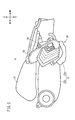
- FIG. 5 is a diagram schematically showing a structure around an opening as seen from the front direction (direction A in arrow view of FIG. 4).
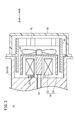
- FIG. 6 is a diagram schematically showing a structure around an opening cut along the VI-VI line of FIG.
- crankcase structure according to the present invention will be described in detail with reference to the attached drawings with reference to suitable embodiments.
- the motorcycle 10 includes a swing unit 12 that is long in the front-rear direction.
- the front portion of the swing unit 12 is held by the frame (not shown) of the motorcycle 10 via the link member 90 (FIG. 5).
- the rear portion of the swing unit 12 is held by the frame (not shown) of the motorcycle 10 via the rear cushion 16.
- An air cleaner 18 is provided in the upward direction of the swing unit 12.
- the swing unit 12 stores the crankshaft 28 (FIG. 3), each part of the drive train, and electrical components such as the generator 30 in the crankcase 22.
- the crankcase 22 has a right crankcase 22a (FIG. 2) arranged on the right side of the center of the motorcycle 10 in the width direction and a left crankcase 22b (FIG. 1) arranged on the left side.
- the right crankcase 22a also functions as a generator case.
- the left crankcase 22b also functions as a belt case extending in the rear direction and a gear case.
- the crankcase structure includes a right crankcase 22a, a crankshaft 28 extending in the width direction (left-right direction), and a crankshaft 28 extending to the right along the axis of the crankshaft 28. It has a generator 30, a fan 40, and a radiator 42, which are arranged in order.
- the generator 30 is housed in the right crankcase 22a together with the crankshaft 28.
- the stator 32 of the generator 30 is attached to the right crankcase 22a.
- a coil is provided in the stator 32, and a cable 36 that outputs electric power to the outside is connected to the stator 32.
- the outer rotor 34 of the generator 30 is arranged so as to cover the outer circumference and the right side of the stator 32.
- the center of the stator 32 penetrates in the width direction, and the right side portion of the crankshaft 28 and the inner center portion of the outer rotor 34 are connected by the penetrating portion.
- the fan 40 is formed on the right side surface of the outer rotor 34.
- the radiator 42 is arranged so as to face the fan 40 and is supported by the radiator cover 44.
- the radiator cover 44 is attached to the right crankcase 22a.
- the cover member 50 is arranged outside the radiator 42 and is attached to at least one of the radiator cover 44 and the right crankcase 22a.
- FIG. 4 schematically shows the internal structure of the right crankcase 22a as seen from the right side.
- the iron core of the stator 32 is shown, but the coil is not shown.
- the cable 36 is shown by a broken line.
- the right crankcase 22a is formed with an opening 60 for pulling out the cable 36 to the outside.
- the opening 60 is formed in a part of the wall portion 38 arranged on the outer periphery of the stator 32 in the right crankcase 22a, and in the present embodiment, in the wall portion 38 arranged on the front side of the stator 32. Will be done.
- the opening 60 is surrounded in the circumferential direction by a member constituting the right crankcase 22a.
- a grommet mounting portion 62 is formed on a part of the peripheral edge portion surrounding the opening 60, that is, the central side (left side) in the width direction in the present embodiment.
- the grommet mounting portion 62 extends along the left peripheral edge 60a of the opening 60 and a part 60b, 60c of the upper and lower peripheral edges, and projects inward of the opening 60.
- a bridge portion 64 is formed in a portion of the peripheral edge portion surrounding the opening 60 that faces the grommet mounting portion 62 with the opening 60 in between.
- the bridge portion 64 is offset with respect to the grommet mounting portion 62 when viewed from a direction orthogonal to the direction in which the cable 36 passes through the opening 60. For example, as shown in FIGS. 4 and 6, when viewed from the right, the bridge portion 64 is offset in the forward direction with respect to the grommet mounting portion 62. Further, as shown in FIG. 5, the bridge portion 64 has a bulging portion 64a that bulges outward (right side) in the width direction.
- a grommet 70 for holding the cable 36 in the opening 60 is attached to the grommet mounting portion 62.
- a groove 72 is formed at the upper and lower ends and the left end of the grommet 70.
- the grommet 70 is formed with a hole through which the cable 36 is passed.
- the grommet 70 may be composed of one member, or may be composed of two or more divided members 70a in combination.
- the radiator cover 44 covers the right side of the right crankcase 22a. That is, when viewed from the right, the radiator cover 44 overlaps the grommet 70 and a part of the bridge portion 64. As shown in FIGS. 5 and 6, the radiator cover 44 has an extending portion 46 extending toward the center in the width direction at a position facing the grommet mounting portion 62. With the grommet 70 fitted to the grommet mounting portion 62, the extension portion 46 faces the grommet mounting portion 62 with the grommet 70 interposed therebetween. Then, the left end of the extending portion 46 approaches or abuts on the right end portion of the grommet 70 fitted to the grommet mounting portion 62.
- the right crankcase 22a is formed with a support portion 80 that is fastened to the link member 90 connected to the frame by the fastening member 86.
- the support portion 80 is formed on the upward side of the bridge portion 64 and the opening 60. At least a part of the support portion 80 and at least a part of the fastening member 86 are arranged inside the bulging portion 64a in the width direction (center side of the vehicle) with respect to the outer end portion 64b (right end portion) in the width direction.
- each part of the support portion 80 and the position of at least a part of the fastening member 86 are inside in the width direction (on the vehicle center side) from the position of the outer end portion 64b (right end portion) of the bulging portion 64a. ..
- the generator 30 is illustrated as an electrical component housed in the right crankcase 22a.
- the electrical components are not limited to the generator 30.
- the electrical component may be a drive motor.
- the present invention can be used in a structure in which the cable 36 is used to transmit and receive electric power inside and outside the crankcase 22.
- FIG. 10 A crankcase structure of a motorcycle 10 that stores electrical components (generator 30) inside the crankcase 22 (right crankcase 22a).
- An opening 60 is formed in the wall portion 38 surrounding the electrical component (generator 30) of the crankcase 22 (right crankcase 22a).
- the cable 36 of the electrical component (generator 30) is held by the grommet 70, and is held.
- a grommet mounting portion 62 to which at least a part of the grommet 70 is mounted is formed in the opening 60, and the grommet mounting portion 62 is formed.
- a bridge portion 64 is formed at a position facing the grommet mounting portion 62 with the opening 60 in between.
- the wall portion 38 of the crankcase 22 (right crankcase 22a)
- the wall portion 38 surrounding the electrical component (generator 30) is formed with an opening 60 instead of a notch, so that the crankcase 22 ( It is possible to prevent the right crankcase 22a) from becoming less rigid. Therefore, the diameter of the cable 36 may be increased, or a structure in which a load is applied to the crankcase 22 (right crankcase 22a) may be used. As described above, according to the above configuration, the degree of freedom in designing the peripheral structure of the cable 36 and the crankcase 22 can be improved.
- the bridge portion 64 may be biased with respect to the grommet mounting portion 62 when viewed from a direction orthogonal to the direction in which the cable 36 passes through the opening 60.
- the grommet 70 can be easily attached to the grommet mounting portion 62.
- the grommet 70 may be a combination of two or more dividing members 70a.
- the grommet 70 is composed of two or more split members 70a, the grommet 70 can be easily attached to the grommet attachment portion 62. Further, it can correspond to various cables 36 having different diameters. Further, when the grommet 70 is replaced, the portion that does not need to be replaced can be reused, so that the cost can be suppressed.
- a radiator 42 supported by a radiator cover 44 is attached to the crankcase 22 (right crankcase 22a).
- One end of the grommet 70 may be attached to the grommet mounting portion 62, and the other end of the grommet 70 may be covered with the radiator cover 44.
- the grommet 70 can be held in the opening 60 by the radiator cover 44 of the existing radiator 42, so that an increase in the number of parts can be suppressed.
- the radiator cover 44 is provided with an extension portion 46 close to the grommet 70.
- the grommet mounting portion 62 and the extending portion 46 may be provided at positions facing each other with the grommet 70 interposed therebetween.
- the grommet mounting portion 62 and the extension portion 46 of the radiator cover 44 are arranged at positions facing each other with the grommet 70 sandwiched between them, the grommet 70 is positioned by the grommet mounting portion 62 and the extension portion 46. Can be held in.
- a support portion 80 to be fastened by a fastening member 86 is formed on the frame side of the motorcycle 10 in the crankcase 22 (right crankcase 22a). At least a part of the support portion 80 may be arranged inside the outer end portion 64b in the width direction of the bridge portion 64 in the width direction.
- the bridge portion 64 (bulging portion 64a) can suppress the influence of an external force from the bridge portion 64 side (outside in the width direction) to the fastening member 86 side (inside in the width direction).
- crankcase structure according to the present invention is not limited to the above-described embodiment, and it goes without saying that various configurations can be adopted without departing from the gist of the present invention.
Landscapes
- Engineering & Computer Science (AREA)
- Chemical & Material Sciences (AREA)
- Combustion & Propulsion (AREA)
- Mechanical Engineering (AREA)
- General Engineering & Computer Science (AREA)
- Transportation (AREA)
- Cylinder Crankcases Of Internal Combustion Engines (AREA)
- Motorcycle And Bicycle Frame (AREA)
Abstract
ケーブルやクランクケースの周辺構造の設計の自由度を向上させる。クランクケース(22)(右クランクケース(22a))の内側に電装品(ジェネレータ(30))を収納する自動二輪車(10)のクランクケース構造であって、クランクケース(22)(右クランクケース(22a))の電装品(ジェネレータ(30))を囲む壁部(38)には開口(60)が形成され、電装品(ジェネレータ(30))のケーブル(36)は、グロメット(70)で保持され、開口(60)には前記グロメット(70)の少なくとも一部が取り付けられるグロメット取付部(62)が形成されるとともに、前記開口(60)を挟んで前記グロメット取付部(62)と対向する位置にブリッジ部(64)が形成される。
Description
本発明は、クランクケースの内側に電装品を収納する自動二輪車のクランクケース構造に関する。
特開2018-66339号公報には、自動二輪車のエンジンを構成するクランクケースが示される。クランクケースは、内側にクランクシャフトとジェネレータ(ACG)を収納する。ジェネレータは、クランクシャフトに接続されるロータと、ロータの内側に配置されるステータと、を有する。ロータにはコイルが設けられる。コイルはケーブルに接続され、ケーブルは整流回路を介してバッテリに接続される。
クランクケースには、ジェネレータ等の電装品のケーブルをクランクケースの内側から外側に引き出すための切欠きが形成される。しかし、切欠きが大きすぎると、クランクケースの剛性が低くなる。クランクケースの剛性を一定以上にするためには切欠きを小さくする必要があり、結果として、ケーブルの太さの上限値を低くしなければならない。また、クランクケースへの偏った応力集中を防止するためには切欠きの周辺に高い負荷がかかる構造を避ける必要がある。このように、クランクケースに切欠きが形成されると、クランクケースから引き出されるケーブルやクランクケースの周辺構造を設計する際に自由度が制限される。
本発明はこのような課題を考慮してなされたものであり、ケーブルやクランクケースの周辺構造の設計の自由度を向上させることを目的とする。
本発明の態様は、
クランクケースの内側に電装品を収納する自動二輪車のクランクケース構造であって、
前記クランクケースの前記電装品を囲む壁部には開口が形成され、
前記電装品のケーブルは、グロメットで保持され、
前記開口には前記グロメットの少なくとも一部が取り付けられるグロメット取付部が形成されるとともに、
前記開口を挟んで前記グロメット取付部と対向する位置にブリッジ部が形成される。
クランクケースの内側に電装品を収納する自動二輪車のクランクケース構造であって、
前記クランクケースの前記電装品を囲む壁部には開口が形成され、
前記電装品のケーブルは、グロメットで保持され、
前記開口には前記グロメットの少なくとも一部が取り付けられるグロメット取付部が形成されるとともに、
前記開口を挟んで前記グロメット取付部と対向する位置にブリッジ部が形成される。
本発明によれば、ケーブルやクランクケースの周辺構造の設計の自由度を向上させることができる。
以下、本発明に係るクランクケース構造について、好適な実施形態を挙げ、添付の図面を参照して詳細に説明する。
図1、図2に示されるように、本実施形態に係る自動二輪車10は、前後方向に長尺であるスイングユニット12を備える。スイングユニット12の前部は、リンク部材90(図5)を介して自動二輪車10のフレーム(不図示)に保持される。また、スイングユニット12の後部は、リアクッション16を介して自動二輪車10のフレーム(不図示)に保持される。スイングユニット12の上方向には、エアクリーナ18が設けられる。
スイングユニット12は、クランクシャフト28(図3)、ドライブトレインの各部品、および、ジェネレータ30等の電装品をクランクケース22に収納する。クランクケース22は、自動二輪車10の幅方向中心よりも右側に配置される右クランクケース22a(図2)と左側に配置される左クランクケース22b(図1)とを有する。右クランクケース22aはジェネレータケースとしても機能する。左クランクケース22bは、後方向に延出するベルトケース、および、ギアケースとしても機能する。
図3に示されるように、本実施形態に係るクランクケース構造は、右クランクケース22aと、幅方向(左右方向)に延出するクランクシャフト28と、クランクシャフト28の軸線に沿って右方向に順に並べられるジェネレータ30と、ファン40と、ラジエータ42と、を有する。ジェネレータ30は、クランクシャフト28とともに右クランクケース22aに収納される。ジェネレータ30のステータ32は、右クランクケース22aに取り付けられる。ステータ32には、コイルが設けられており、電力を外部に出力するケーブル36が接続される。ジェネレータ30のアウタロータ34は、ステータ32の外周および右側を覆うように配置される。ステータ32の中心は幅方向に貫通しており、その貫通部分で、クランクシャフト28の右側の部分とアウタロータ34の内側中心部とが接続される。ファン40は、アウタロータ34の右側面に形成される。ラジエータ42は、ファン40と対向するように配置され、ラジエータカバー44により支持される。ラジエータカバー44は、右クランクケース22aに取り付けられる。カバー部材50は、ラジエータ42の外側に配置され、ラジエータカバー44と右クランクケース22aの少なくとも一方に取り付けられる。
図4は、右側から見た右クランクケース22aの内部構造を模式的に示す。ここでは、ステータ32の鉄心が示される一方でコイルは示されていない。但し、図4ではケーブル36が破線で示される。図4、図5に示されるように、右クランクケース22aにはケーブル36を外部に引き出すための開口60が形成される。具体的には、開口60は、右クランクケース22aのうち、ステータ32の外周に配置される壁部38の一部、本実施形態ではステータ32の前方向側に配置される壁部38に形成される。開口60は、切欠きと異なり、右クランクケース22aを構成する部材によって周方向を取り囲まれる。
開口60を取り囲む周縁部分のうちの一部分、本実施形態では幅方向の中心側(左側)の部分には、グロメット取付部62が形成される。グロメット取付部62は、開口60の左側周縁60aおよび上下周縁の一部60b、60cに沿って拡がり、開口60の内側に突出する。また、開口60を取り囲む周縁部分のうち、開口60を挟んでグロメット取付部62と対向する部分には、ブリッジ部64が形成される。
ブリッジ部64は、ケーブル36が開口60を通る方向と直交する方向から見て、グロメット取付部62に対して偏倚(オフセット)する。例えば、図4、図6に示されるように、右方向から見て、ブリッジ部64は、グロメット取付部62に対して前方向に偏倚(オフセット)する。また、図5に示されるように、ブリッジ部64は、幅方向の外側(右側)に膨出する膨出部64aを有する。
図5、図6に示されるように、グロメット取付部62には、開口60内でケーブル36を保持するためのグロメット70が取り付けられる。グロメット70の上下端部および左端部には溝72が形成される。グロメット70が幅方向の外側(右側)からグロメット取付部62に対して押し込まれると、グロメット70の溝72にグロメット取付部62が嵌め合わされる。グロメット70にはケーブル36を通す孔が形成される。なお、グロメット70は、1つの部材から構成されてもよいし、2以上の分割部材70aが組み合わされて構成されてもよい。
ラジエータカバー44は、右クランクケース22aの右側を覆う。すなわち、右方向から見て、ラジエータカバー44は、グロメット70とブリッジ部64の一部と重なる。図5、図6に示されるように、ラジエータカバー44は、グロメット取付部62と対向する位置に、幅方向の中心側に延出する延出部46を有する。グロメット70がグロメット取付部62に嵌め合わされた状態で、延出部46は、グロメット70を挟んでグロメット取付部62と対向する。そして、延出部46の左端は、グロメット取付部62に嵌め合わされたグロメット70の右端部に近接または当接する。
図5に示されるように、右クランクケース22aには、フレームに接続されるリンク部材90に対して締結部材86で締結される支持部80が形成される。支持部80は、ブリッジ部64および開口60よりも上方向側に形成される。支持部80の少なくとも一部と、締結部材86の少なくとも一部は、膨出部64aの幅方向における外側端部64b(右端部)よりも幅方向内側(車両中央側)に配置される。言い換えると、支持部80の各部の位置と、締結部材86の少なくとも一部の位置は、膨出部64aの外側端部64b(右端部)の位置よりも幅方向内側(車両中央側)である。
なお、上述した実施形態では、右クランクケース22aに収納される電装品としてジェネレータ30を例示する。しかし、電装品は、ジェネレータ30に限らない。例えば、自動二輪車10が電動車両である場合、電装品は駆動用のモータであってもよい。このように、本発明は、ケーブル36を使用してクランクケース22の内外で電力の送受電を行う構造に使用可能である。
上記実施形態および変形例から把握しうる技術的思想について、以下に記載する。
本発明の態様は、
クランクケース22(右クランクケース22a)の内側に電装品(ジェネレータ30)を収納する自動二輪車10のクランクケース構造であって、
前記クランクケース22(右クランクケース22a)の前記電装品(ジェネレータ30)を囲む壁部38には開口60が形成され、
前記電装品(ジェネレータ30)のケーブル36は、グロメット70で保持され、
前記開口60には前記グロメット70の少なくとも一部が取り付けられるグロメット取付部62が形成されるとともに、
前記開口60を挟んで前記グロメット取付部62と対向する位置にブリッジ部64が形成される。
クランクケース22(右クランクケース22a)の内側に電装品(ジェネレータ30)を収納する自動二輪車10のクランクケース構造であって、
前記クランクケース22(右クランクケース22a)の前記電装品(ジェネレータ30)を囲む壁部38には開口60が形成され、
前記電装品(ジェネレータ30)のケーブル36は、グロメット70で保持され、
前記開口60には前記グロメット70の少なくとも一部が取り付けられるグロメット取付部62が形成されるとともに、
前記開口60を挟んで前記グロメット取付部62と対向する位置にブリッジ部64が形成される。
上記構成によれば、クランクケース22(右クランクケース22a)の壁部38のうち、電装品(ジェネレータ30)を囲む壁部38に切欠きでなく開口60が形成されるため、クランクケース22(右クランクケース22a)の剛性が低くなることを抑制することができる。従って、ケーブル36の径を太くしてもよいし、クランクケース22(右クランクケース22a)に負荷がかかる構造を使用してもよい。このように、上記構成によれば、ケーブル36やクランクケース22の周辺構造の設計の自由度を向上させることができる。
本発明の態様において、
前記ケーブル36が前記開口60を通る方向と直交する方向から見て、前記ブリッジ部64は、前記グロメット取付部62に対して偏倚してもよい。
前記ケーブル36が前記開口60を通る方向と直交する方向から見て、前記ブリッジ部64は、前記グロメット取付部62に対して偏倚してもよい。
上記構成によれば、グロメット取付部62に対してブリッジ部64が偏倚(オフセット)するため、グロメット取付部62に対するグロメット70の取り付けを容易に行うことができる。
本発明の態様において、
前記グロメット70は、2以上の分割部材70aが組み合わされてもよい。
前記グロメット70は、2以上の分割部材70aが組み合わされてもよい。
上記構成によれば、グロメット70が2以上の分割部材70aからなるため、グロメット取付部62に対するグロメット70の取り付けを容易に行うことができる。また、径の異なる様々なケーブル36に対応することができる。また、グロメット70の交換時に、交換が不要な部分を再利用することができるため、コストを抑制することができる。
本発明において、
前記クランクケース22(右クランクケース22a)にラジエータカバー44で支持されるラジエータ42が取り付けられ、
前記グロメット70の一端は前記グロメット取付部62に取り付けられ、前記グロメット70の他端は前記ラジエータカバー44で覆われてもよい。
前記クランクケース22(右クランクケース22a)にラジエータカバー44で支持されるラジエータ42が取り付けられ、
前記グロメット70の一端は前記グロメット取付部62に取り付けられ、前記グロメット70の他端は前記ラジエータカバー44で覆われてもよい。
上記構成によれば、既存するラジエータ42のラジエータカバー44によりグロメット70を開口60に保持することができるために、部品点数の増加を抑えることができる。
本発明の態様において、
前記ラジエータカバー44には前記グロメット70に近接する延出部46が設けられ、
前記グロメット70を挟んで前記グロメット取付部62と前記延出部46は、互いに対向する位置に設けられてもよい。
前記ラジエータカバー44には前記グロメット70に近接する延出部46が設けられ、
前記グロメット70を挟んで前記グロメット取付部62と前記延出部46は、互いに対向する位置に設けられてもよい。
上記構成によれば、グロメット70を挟んでグロメット取付部62とラジエータカバー44の延出部46が互いに対向する位置に配置されるため、グロメット取付部62と延出部46によりグロメット70を定位置に保持することができる。
本発明の態様において、
前記クランクケース22(右クランクケース22a)には前記自動二輪車10のフレーム側に締結部材86で締結される支持部80が形成され、
前記支持部80の少なくとも一部は、前記ブリッジ部64の幅方向における外側端部64bよりも幅方向内側に配置されてもよい。
前記クランクケース22(右クランクケース22a)には前記自動二輪車10のフレーム側に締結部材86で締結される支持部80が形成され、
前記支持部80の少なくとも一部は、前記ブリッジ部64の幅方向における外側端部64bよりも幅方向内側に配置されてもよい。
上記構成によれば、ブリッジ部64(膨出部64a)により、ブリッジ部64側(幅方向外側)から締結部材86側(幅方向内側)への外力の影響を抑制することができる。
なお、本発明に係るクランクケース構造は、上述の実施形態に限らず、本発明の要旨を逸脱することなく、種々の構成を採り得ることはもちろんである。
Claims (6)
- クランクケース(22)の内側に電装品(30)を収納する自動二輪車(10)のクランクケース構造であって、
前記クランクケース(22)の前記電装品(30)を囲む壁部(38)には開口(60)が形成され、
前記電装品(30)のケーブル(36)は、グロメット(70)で保持され、
前記開口(60)には前記グロメット(70)の少なくとも一部が取り付けられるグロメット取付部(62)が形成されるとともに、
前記開口(60)を挟んで前記グロメット取付部(62)と対向する位置にブリッジ部(64)が形成される、クランクケース構造。 - 請求項1に記載のクランクケース構造であって、
前記ケーブル(36)が前記開口(60)を通る方向と直交する方向から見て、前記ブリッジ部(64)は、前記グロメット取付部(62)に対して偏倚する、クランクケース構造。 - 請求項1または2に記載のクランクケース構造であって、
前記グロメット(70)は、2以上の分割部材(70a)が組み合わされてなる、クランクケース構造。 - 請求項3に記載のクランクケース構造であって、
前記クランクケース(22)にラジエータカバー(44)で支持されるラジエータ(42)が取り付けられ、
前記グロメット(70)の一端は前記グロメット取付部(62)に取り付けられ、前記グロメット(70)の他端は前記ラジエータカバー(44)で覆われる、クランクケース構造。 - 請求項4に記載のクランクケース構造であって、
前記ラジエータカバー(44)には前記グロメット(70)に近接する延出部(46)が設けられ、
前記グロメット(70)を挟んで前記グロメット取付部(62)と前記延出部(46)は、互いに対向する位置に設けられる、クランクケース構造。 - 請求項1~5のいずれか1項に記載のクランクケース構造であって、
前記クランクケース(22)には前記自動二輪車(10)のフレーム側に締結部材(86)で締結される支持部(80)が形成され、
前記支持部(80)の少なくとも一部は、前記ブリッジ部(64)の幅方向における外側端部(64b)よりも幅方向内側に配置される、クランクケース構造。
Priority Applications (1)
| Application Number | Priority Date | Filing Date | Title |
|---|---|---|---|
| JP2021511461A JP7051002B2 (ja) | 2019-03-29 | 2020-03-23 | クランクケース構造 |
Applications Claiming Priority (2)
| Application Number | Priority Date | Filing Date | Title |
|---|---|---|---|
| JP2019-065346 | 2019-03-29 | ||
| JP2019065346 | 2019-03-29 |
Publications (1)
| Publication Number | Publication Date |
|---|---|
| WO2020203385A1 true WO2020203385A1 (ja) | 2020-10-08 |
Family
ID=72667638
Family Applications (1)
| Application Number | Title | Priority Date | Filing Date |
|---|---|---|---|
| PCT/JP2020/012582 Ceased WO2020203385A1 (ja) | 2019-03-29 | 2020-03-23 | クランクケース構造 |
Country Status (2)
| Country | Link |
|---|---|
| JP (1) | JP7051002B2 (ja) |
| WO (1) | WO2020203385A1 (ja) |
Cited By (1)
| Publication number | Priority date | Publication date | Assignee | Title |
|---|---|---|---|---|
| WO2025203331A1 (ja) * | 2024-03-27 | 2025-10-02 | 本田技研工業株式会社 | 電動車両 |
Citations (4)
| Publication number | Priority date | Publication date | Assignee | Title |
|---|---|---|---|---|
| JPS56173727U (ja) * | 1980-05-26 | 1981-12-22 | ||
| JPH11229891A (ja) * | 1998-02-18 | 1999-08-24 | Honda Motor Co Ltd | エンジンのグロメット取付構造及びエンジン構造 |
| JP2010190135A (ja) * | 2009-02-19 | 2010-09-02 | Honda Motor Co Ltd | 内燃機関のクランクケース構造 |
| JP2015116004A (ja) * | 2013-12-10 | 2015-06-22 | 本田技研工業株式会社 | 内燃機関のジェネレータ冷却構造 |
Family Cites Families (2)
| Publication number | Priority date | Publication date | Assignee | Title |
|---|---|---|---|---|
| JPH08198162A (ja) * | 1995-01-25 | 1996-08-06 | Mitsubishi Heavy Ind Ltd | 原動機付自転車 |
| JP2005210854A (ja) * | 2004-01-23 | 2005-08-04 | Yamaha Motor Co Ltd | ケースの線状部材シール構造 |
-
2020
- 2020-03-23 WO PCT/JP2020/012582 patent/WO2020203385A1/ja not_active Ceased
- 2020-03-23 JP JP2021511461A patent/JP7051002B2/ja active Active
Patent Citations (4)
| Publication number | Priority date | Publication date | Assignee | Title |
|---|---|---|---|---|
| JPS56173727U (ja) * | 1980-05-26 | 1981-12-22 | ||
| JPH11229891A (ja) * | 1998-02-18 | 1999-08-24 | Honda Motor Co Ltd | エンジンのグロメット取付構造及びエンジン構造 |
| JP2010190135A (ja) * | 2009-02-19 | 2010-09-02 | Honda Motor Co Ltd | 内燃機関のクランクケース構造 |
| JP2015116004A (ja) * | 2013-12-10 | 2015-06-22 | 本田技研工業株式会社 | 内燃機関のジェネレータ冷却構造 |
Cited By (1)
| Publication number | Priority date | Publication date | Assignee | Title |
|---|---|---|---|---|
| WO2025203331A1 (ja) * | 2024-03-27 | 2025-10-02 | 本田技研工業株式会社 | 電動車両 |
Also Published As
| Publication number | Publication date |
|---|---|
| JP7051002B2 (ja) | 2022-04-08 |
| JPWO2020203385A1 (ja) | 2021-12-23 |
Similar Documents
| Publication | Publication Date | Title |
|---|---|---|
| JP6349415B2 (ja) | ハイブリッド車両用駆動装置 | |
| CN204497914U (zh) | 电动机的冷却装置和电动机 | |
| JP4089623B2 (ja) | 回転電機 | |
| JP2016022799A (ja) | 電動車両 | |
| EP2698564A1 (en) | Power transmission device | |
| JP7051002B2 (ja) | クランクケース構造 | |
| US20150236573A1 (en) | Case structure for driving apparatus | |
| JP2012241687A (ja) | 船外機 | |
| WO2011111299A1 (ja) | 電動自転車 | |
| JP2024047785A (ja) | 駆動装置 | |
| WO2015063924A1 (ja) | 車両用回転電機 | |
| CN105682964A (zh) | 动力产生装置 | |
| JP2018085208A (ja) | コネクタ | |
| JP6077851B2 (ja) | 端子台の周辺構造 | |
| JPWO2012014969A1 (ja) | モールドモータ及びこれを搭載した移動体 | |
| CN110182146A (zh) | 车辆用驱动装置 | |
| US12199489B2 (en) | Vehicle drive device | |
| JP2007221879A (ja) | 車両用交流発電機 | |
| JP2005143152A (ja) | 車両用交流発電機 | |
| US20100176684A1 (en) | Dynamoelectric machine | |
| TWI644015B (zh) | 引擎 | |
| JP2011078258A (ja) | 電動発電機の支持構造 | |
| JP5764437B2 (ja) | エンジンのワイヤハーネス配索構造 | |
| JP6897506B2 (ja) | マウント | |
| JP5146074B2 (ja) | 車両用交流発電機 |
Legal Events
| Date | Code | Title | Description |
|---|---|---|---|
| 121 | Ep: the epo has been informed by wipo that ep was designated in this application |
Ref document number: 20781291 Country of ref document: EP Kind code of ref document: A1 |
|
| ENP | Entry into the national phase |
Ref document number: 2021511461 Country of ref document: JP Kind code of ref document: A |
|
| NENP | Non-entry into the national phase |
Ref country code: DE |
|
| 122 | Ep: pct application non-entry in european phase |
Ref document number: 20781291 Country of ref document: EP Kind code of ref document: A1 |