EP2698564A1 - Power transmission device - Google Patents
Power transmission device Download PDFInfo
- Publication number
- EP2698564A1 EP2698564A1 EP11863397.3A EP11863397A EP2698564A1 EP 2698564 A1 EP2698564 A1 EP 2698564A1 EP 11863397 A EP11863397 A EP 11863397A EP 2698564 A1 EP2698564 A1 EP 2698564A1
- Authority
- EP
- European Patent Office
- Prior art keywords
- rotating electric
- case
- electric machine
- motive power
- power transmission
- Prior art date
- Legal status (The legal status is an assumption and is not a legal conclusion. Google has not performed a legal analysis and makes no representation as to the accuracy of the status listed.)
- Granted
Links
Images

Classifications
-
- H—ELECTRICITY
- H02—GENERATION; CONVERSION OR DISTRIBUTION OF ELECTRIC POWER
- H02K—DYNAMO-ELECTRIC MACHINES
- H02K51/00—Dynamo-electric gears, i.e. dynamo-electric means for transmitting mechanical power from a driving shaft to a driven shaft and comprising structurally interrelated motor and generator parts
-
- B—PERFORMING OPERATIONS; TRANSPORTING
- B60—VEHICLES IN GENERAL
- B60K—ARRANGEMENT OR MOUNTING OF PROPULSION UNITS OR OF TRANSMISSIONS IN VEHICLES; ARRANGEMENT OR MOUNTING OF PLURAL DIVERSE PRIME-MOVERS IN VEHICLES; AUXILIARY DRIVES FOR VEHICLES; INSTRUMENTATION OR DASHBOARDS FOR VEHICLES; ARRANGEMENTS IN CONNECTION WITH COOLING, AIR INTAKE, GAS EXHAUST OR FUEL SUPPLY OF PROPULSION UNITS IN VEHICLES
- B60K6/00—Arrangement or mounting of plural diverse prime-movers for mutual or common propulsion, e.g. hybrid propulsion systems comprising electric motors and internal combustion engines ; Control systems therefor, i.e. systems controlling two or more prime movers, or controlling one of these prime movers and any of the transmission, drive or drive units Informative references: mechanical gearings with secondary electric drive F16H3/72; arrangements for handling mechanical energy structurally associated with the dynamo-electric machine H02K7/00; machines comprising structurally interrelated motor and generator parts H02K51/00; dynamo-electric machines not otherwise provided for in H02K see H02K99/00
- B60K6/20—Arrangement or mounting of plural diverse prime-movers for mutual or common propulsion, e.g. hybrid propulsion systems comprising electric motors and internal combustion engines ; Control systems therefor, i.e. systems controlling two or more prime movers, or controlling one of these prime movers and any of the transmission, drive or drive units Informative references: mechanical gearings with secondary electric drive F16H3/72; arrangements for handling mechanical energy structurally associated with the dynamo-electric machine H02K7/00; machines comprising structurally interrelated motor and generator parts H02K51/00; dynamo-electric machines not otherwise provided for in H02K see H02K99/00 the prime-movers consisting of electric motors and internal combustion engines, e.g. HEVs
- B60K6/22—Arrangement or mounting of plural diverse prime-movers for mutual or common propulsion, e.g. hybrid propulsion systems comprising electric motors and internal combustion engines ; Control systems therefor, i.e. systems controlling two or more prime movers, or controlling one of these prime movers and any of the transmission, drive or drive units Informative references: mechanical gearings with secondary electric drive F16H3/72; arrangements for handling mechanical energy structurally associated with the dynamo-electric machine H02K7/00; machines comprising structurally interrelated motor and generator parts H02K51/00; dynamo-electric machines not otherwise provided for in H02K see H02K99/00 the prime-movers consisting of electric motors and internal combustion engines, e.g. HEVs characterised by apparatus, components or means specially adapted for HEVs
- B60K6/40—Arrangement or mounting of plural diverse prime-movers for mutual or common propulsion, e.g. hybrid propulsion systems comprising electric motors and internal combustion engines ; Control systems therefor, i.e. systems controlling two or more prime movers, or controlling one of these prime movers and any of the transmission, drive or drive units Informative references: mechanical gearings with secondary electric drive F16H3/72; arrangements for handling mechanical energy structurally associated with the dynamo-electric machine H02K7/00; machines comprising structurally interrelated motor and generator parts H02K51/00; dynamo-electric machines not otherwise provided for in H02K see H02K99/00 the prime-movers consisting of electric motors and internal combustion engines, e.g. HEVs characterised by apparatus, components or means specially adapted for HEVs characterised by the assembly or relative disposition of components
- B60K6/405—Housings
-
- H—ELECTRICITY
- H02—GENERATION; CONVERSION OR DISTRIBUTION OF ELECTRIC POWER
- H02K—DYNAMO-ELECTRIC MACHINES
- H02K1/00—Details of the magnetic circuit
- H02K1/06—Details of the magnetic circuit characterised by the shape, form or construction
- H02K1/12—Stationary parts of the magnetic circuit
- H02K1/18—Means for mounting or fastening magnetic stationary parts on to, or to, the stator structures
- H02K1/185—Means for mounting or fastening magnetic stationary parts on to, or to, the stator structures to outer stators
-
- H—ELECTRICITY
- H02—GENERATION; CONVERSION OR DISTRIBUTION OF ELECTRIC POWER
- H02K—DYNAMO-ELECTRIC MACHINES
- H02K16/00—Machines with more than one rotor or stator
-
- H—ELECTRICITY
- H02—GENERATION; CONVERSION OR DISTRIBUTION OF ELECTRIC POWER
- H02K—DYNAMO-ELECTRIC MACHINES
- H02K5/00—Casings; Enclosures; Supports
- H02K5/04—Casings or enclosures characterised by the shape, form or construction thereof
-
- B—PERFORMING OPERATIONS; TRANSPORTING
- B60—VEHICLES IN GENERAL
- B60K—ARRANGEMENT OR MOUNTING OF PROPULSION UNITS OR OF TRANSMISSIONS IN VEHICLES; ARRANGEMENT OR MOUNTING OF PLURAL DIVERSE PRIME-MOVERS IN VEHICLES; AUXILIARY DRIVES FOR VEHICLES; INSTRUMENTATION OR DASHBOARDS FOR VEHICLES; ARRANGEMENTS IN CONNECTION WITH COOLING, AIR INTAKE, GAS EXHAUST OR FUEL SUPPLY OF PROPULSION UNITS IN VEHICLES
- B60K6/00—Arrangement or mounting of plural diverse prime-movers for mutual or common propulsion, e.g. hybrid propulsion systems comprising electric motors and internal combustion engines ; Control systems therefor, i.e. systems controlling two or more prime movers, or controlling one of these prime movers and any of the transmission, drive or drive units Informative references: mechanical gearings with secondary electric drive F16H3/72; arrangements for handling mechanical energy structurally associated with the dynamo-electric machine H02K7/00; machines comprising structurally interrelated motor and generator parts H02K51/00; dynamo-electric machines not otherwise provided for in H02K see H02K99/00
- B60K6/20—Arrangement or mounting of plural diverse prime-movers for mutual or common propulsion, e.g. hybrid propulsion systems comprising electric motors and internal combustion engines ; Control systems therefor, i.e. systems controlling two or more prime movers, or controlling one of these prime movers and any of the transmission, drive or drive units Informative references: mechanical gearings with secondary electric drive F16H3/72; arrangements for handling mechanical energy structurally associated with the dynamo-electric machine H02K7/00; machines comprising structurally interrelated motor and generator parts H02K51/00; dynamo-electric machines not otherwise provided for in H02K see H02K99/00 the prime-movers consisting of electric motors and internal combustion engines, e.g. HEVs
- B60K6/22—Arrangement or mounting of plural diverse prime-movers for mutual or common propulsion, e.g. hybrid propulsion systems comprising electric motors and internal combustion engines ; Control systems therefor, i.e. systems controlling two or more prime movers, or controlling one of these prime movers and any of the transmission, drive or drive units Informative references: mechanical gearings with secondary electric drive F16H3/72; arrangements for handling mechanical energy structurally associated with the dynamo-electric machine H02K7/00; machines comprising structurally interrelated motor and generator parts H02K51/00; dynamo-electric machines not otherwise provided for in H02K see H02K99/00 the prime-movers consisting of electric motors and internal combustion engines, e.g. HEVs characterised by apparatus, components or means specially adapted for HEVs
- B60K6/26—Arrangement or mounting of plural diverse prime-movers for mutual or common propulsion, e.g. hybrid propulsion systems comprising electric motors and internal combustion engines ; Control systems therefor, i.e. systems controlling two or more prime movers, or controlling one of these prime movers and any of the transmission, drive or drive units Informative references: mechanical gearings with secondary electric drive F16H3/72; arrangements for handling mechanical energy structurally associated with the dynamo-electric machine H02K7/00; machines comprising structurally interrelated motor and generator parts H02K51/00; dynamo-electric machines not otherwise provided for in H02K see H02K99/00 the prime-movers consisting of electric motors and internal combustion engines, e.g. HEVs characterised by apparatus, components or means specially adapted for HEVs characterised by the motors or the generators
- B60K2006/266—Arrangement or mounting of plural diverse prime-movers for mutual or common propulsion, e.g. hybrid propulsion systems comprising electric motors and internal combustion engines ; Control systems therefor, i.e. systems controlling two or more prime movers, or controlling one of these prime movers and any of the transmission, drive or drive units Informative references: mechanical gearings with secondary electric drive F16H3/72; arrangements for handling mechanical energy structurally associated with the dynamo-electric machine H02K7/00; machines comprising structurally interrelated motor and generator parts H02K51/00; dynamo-electric machines not otherwise provided for in H02K see H02K99/00 the prime-movers consisting of electric motors and internal combustion engines, e.g. HEVs characterised by apparatus, components or means specially adapted for HEVs characterised by the motors or the generators with two coaxial motors or generators
-
- F—MECHANICAL ENGINEERING; LIGHTING; HEATING; WEAPONS; BLASTING
- F16—ENGINEERING ELEMENTS AND UNITS; GENERAL MEASURES FOR PRODUCING AND MAINTAINING EFFECTIVE FUNCTIONING OF MACHINES OR INSTALLATIONS; THERMAL INSULATION IN GENERAL
- F16H—GEARING
- F16H57/00—General details of gearing
- F16H57/02—Gearboxes; Mounting gearing therein
- F16H2057/02034—Gearboxes combined or connected with electric machines
-
- H—ELECTRICITY
- H02—GENERATION; CONVERSION OR DISTRIBUTION OF ELECTRIC POWER
- H02K—DYNAMO-ELECTRIC MACHINES
- H02K7/00—Arrangements for handling mechanical energy structurally associated with dynamo-electric machines, e.g. structural association with mechanical driving motors or auxiliary dynamo-electric machines
- H02K7/10—Structural association with clutches, brakes, gears, pulleys or mechanical starters
- H02K7/108—Structural association with clutches, brakes, gears, pulleys or mechanical starters with friction clutches
-
- H—ELECTRICITY
- H02—GENERATION; CONVERSION OR DISTRIBUTION OF ELECTRIC POWER
- H02K—DYNAMO-ELECTRIC MACHINES
- H02K7/00—Arrangements for handling mechanical energy structurally associated with dynamo-electric machines, e.g. structural association with mechanical driving motors or auxiliary dynamo-electric machines
- H02K7/10—Structural association with clutches, brakes, gears, pulleys or mechanical starters
- H02K7/116—Structural association with clutches, brakes, gears, pulleys or mechanical starters with gears
Definitions
- the present invention relates to a motive power transmission device, and more particularly to a motive power transmission device including two rotating electric machines.
- PTL 1 discloses a transmission containing two rotating electric machines, in which at least one rotating electric machine has a stator fixed to one of housing cases for housing the respective rotating electric machine, on a side having matching surfaces of the cases.
- PTL 2 discloses a motive power transmission device in which two rotating electric machines are housed in one case.
- the present invention has been made to solve the aforementioned problem, and one object of the present invention is to provide a motive power transmission device capable of suppressing deformation of matching surfaces of two cases.
- a motive power transmission device in accordance with the present invention includes a first rotating electric machine axially extending from a first end surface to a second end surface, a first case housing the first rotating electric machine, a first fixing member fixing the first rotating electric machine to the first case on a side having the second end surface, a second rotating electric machine axially extending from a third end surface to a fourth end surface, a second case housing the second rotating electric machine, and a second fixing member fixing the second rotating electric machine to the second case on a side having the fourth end surface, a surface of the first case on a side having the first end surface being bonded to a surface of the second case on a side having the second end surface.
- the first and second rotating electric machines are fixed to the first and second cases on sides opposite to matching surfaces of the first case and the second case, input of vibrations of the rotating electric machines can be reduced in the matching surfaces. As a result, deformation in the matching surfaces of the two cases can be suppressed.
- the motive power transmission device further includes a motive power split mechanism connected to the first rotating electric machine and the second rotating electric machine.
- the motive power transmission device further includes a third fixing member bonding the first and second cases.
- the motive power transmission device further includes a first pedestal interposed between the first rotating electric machine and the first case, and a second pedestal interposed between the second rotating electric machine and the second case.
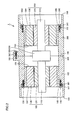
- Fig. 1 is a cross sectional view of first and second rotating electric machines as a motive power transmission device in accordance with Embodiment 1 of the present invention.
- a motive power transmission device 1 includes a first rotating electric machine 100 axially extending from a first end surface 191 to a second end surface 192, a first case 160 housing first rotating electric machine 100, a first fixing member 150 fixing first rotating electric machine 100 to first case 160 on a side having second end surface 192, a second rotating electric machine 200 axially extending from a third end surface 293 to a fourth end surface 294, a second case 260 housing second rotating electric machine 200, and a second fixing member 250 fixing second rotating electric machine 200 to second case 260 on a side having fourth end surface 294, a first matching surface 169 of first case 160 on a side having first end surface 191 being bonded to a second matching surface 269 of second case 260 on a side having third end surface 293.
- Motive power transmission device 1 further includes a third fixing member 350 bonding a flange portion 162 of first case 160 and a flange portion 262 of second case 260.
- a first pedestal 140 is interposed between first rotating electric machine 100 and first case 160, and a second pedestal 240 is interposed between second rotating electric machine 200 and second case 260.
- First case 160 and second case 260 are tubular, and first and second rotating electric machines 100, 200 are housed in internal spaces thereof. Stepped portions 161, 261 are formed in first and second cases 160, 260, and first and second pedestals 140, 240 abut on stepped portions 161, 261.
- first and second cases 160, 260 each include a large-diameter portion with a relatively large inner diameter and a small-diameter portion with a relatively small inner diameter, and flange portions 141, 241 of first and second pedestals 140, 240 are each located in the large-diameter portion, and portions other than flange portions 141, 241 are each located in the small-diameter portion.
- first and second cases 160, 260 are not limited thereto, and an inner peripheral surface as a tapered surface with a gradually decreasing or increasing inner diameter may be provided.
- First and second cases 160, 260 extend from end surfaces 168, 268 to first and second matching surfaces 169, 269.
- the inner peripheral surface is not limited to be cylindrical, and may have a shape of a tubular prism. Further, a portion of the cylindrical inner peripheral surface is provided with a rib, and the rib may axially extend.
- First and second fixing members 150, 250 formed of bolts are inserted into through holes 142, 242 in first and second pedestals 140, 240 and screwed into first and second cases 160, 260. Thereby, first and second pedestals 140, 240 can be fixed to first and second cases 160, 260.
- First and second rotating electric machines 100, 200 have rotatable first and second rotating shafts 110, 210, first and second rotors 120, 220 provided around outer peripheries of first and second rotating shafts 110, 210, and first and second stators 130, 230 arranged to face first and second rotors 120, 220.
- first and second rotors 120, 220 attached to the outer peripheries of first and second rotating shafts 110, 210 also rotate.
- First and second rotors 120, 220 face first and second stators 130, 230.
- a coil is wound around a stator coil.
- both distributed winding and concentrated winding can be adopted.
- a copper wire constituting the coil may be a round wire or a flat wire.
- first and second stators 130, 230 are held by first and second pedestals 140, 240.
- Outer peripheral surfaces of first and second cases 160, 260 are provided with flange portions 162, 262.
- Motive power transmission device 1 in accordance with the present invention is used as a transmission for a hybrid vehicle containing first rotating electric machine 100 and second rotating electric machine 200 as two rotating electric machines.
- First rotating electric machine 100 and second rotating electric machine 200 each serving as a motor/generator are housed in independent first case 160 and second case 260, and the both are coupled to constitute the transmission for a hybrid vehicle.
- First stator 130 and second stator 230 are fastened and fixed to first case 160 and second case 260 on sides opposite to first matching surface 169 and second matching surface 269.
- vibrations of first rotating electric machine 100 are transmitted to first case 160 through first fixing members 150.
- vibrations in the vicinity of first matching surface 169 can be suppressed.
- vibrations of second rotating electric machine 200 are transmitted to second case 260 through second fixing members 250.
- vibrations in the vicinity of second matching surface 269 can be suppressed.
- input of vibrations of the stators to first matching surface 169 and second matching surface 269 is reduced, improving reliability of fastening between the cases.
- heat of first stator 130 is transferred from flange portion 141 to first case 160 through stepped portion 161, heat transfer to first matching surface 169 is suppressed.
- heat of second stator 230 is also suppressed from being transferred to second matching surface 269. As a result, heat is transferred to both ends of motive power transmission device 1, and heat transfer to the center can be suppressed. Thereby, cooling capacity is improved.
- Fig. 2 is a cross sectional view of first and second rotating electric machines as a motive power transmission device in accordance with Embodiment 2 of the present invention.
- motive power transmission device 1 in accordance with Embodiment 2 of the present invention is different from the motive power transmission device in accordance with Embodiment 1 in that a motive power split mechanism 300 is provided between first rotating shaft 110 and second rotating shaft 210.
- Motive power split mechanism 300 is formed of, for example, a planetary gear device.
- Motive power split mechanism 300 is used to split motive power from an engine into motive power for traveling and motive power for generating electric power in a generator.
- one of first rotating shaft 110 and second rotating shaft 210 is connected to the engine.
- first matching surface 169 and second matching surface 269 When motive power split mechanism 300 formed of a planetary gear mechanism is driven, noise and vibrations are generated. However, since transmission of these vibrations to first matching surface 169 and second matching surface 269 is reduced as described in Embodiment 1, deformation in first matching surface 169 and second matching surface 269 can be suppressed.
- 1 motive power transmission device, 100: first rotating electric machine, 110: first rotating shaft, 120: first rotor, 130: first stator, 140: first pedestal, 141, 162, 262: flange portion, 142: through hole, 150: first fixing member, 160: first case, 161: stepped portion, 169: first matching surface, 191: first end surface, 192: second end surface, 200: second rotating electric machine, 210: second rotating shaft, 230: second stator, 240: second pedestal, 250: second fixing member, 260: second case, 269: second matching surface, 293: third end surface, 294: fourth end surface, 300: motive power split mechanism, 350: third fixing member.
Abstract
Description
- The present invention relates to a motive power transmission device, and more particularly to a motive power transmission device including two rotating electric machines.
- Conventionally, motive power transmission devices have been disclosed for example in Japanese Patent Laying-Open No.
2009-149114 2008-265517 -
- PTL 1: Japanese Patent Laying-Open No.
2009-149114 - PTL 2: Japanese Patent Laying-Open No.
2008-265517 - PTL 1 discloses a transmission containing two rotating electric machines, in which at least one rotating electric machine has a stator fixed to one of housing cases for housing the respective rotating electric machine, on a side having matching surfaces of the cases. PTL 2 discloses a motive power transmission device in which two rotating electric machines are housed in one case.
- Conventional motive power transmission devices have a problem that, since input of vibrations of a stator significantly acts on matching surfaces of housing cases, the matching surfaces of the cases have a reduced rigidity, which leads to deformation of the matching surfaces and increased occurrence of a sealing failure.
- Thus, the present invention has been made to solve the aforementioned problem, and one object of the present invention is to provide a motive power transmission device capable of suppressing deformation of matching surfaces of two cases.
- A motive power transmission device in accordance with the present invention includes a first rotating electric machine axially extending from a first end surface to a second end surface, a first case housing the first rotating electric machine, a first fixing member fixing the first rotating electric machine to the first case on a side having the second end surface, a second rotating electric machine axially extending from a third end surface to a fourth end surface, a second case housing the second rotating electric machine, and a second fixing member fixing the second rotating electric machine to the second case on a side having the fourth end surface, a surface of the first case on a side having the first end surface being bonded to a surface of the second case on a side having the second end surface.
- In the motive power transmission device configured as described above, since the first and second rotating electric machines are fixed to the first and second cases on sides opposite to matching surfaces of the first case and the second case, input of vibrations of the rotating electric machines can be reduced in the matching surfaces. As a result, deformation in the matching surfaces of the two cases can be suppressed.
- Preferably, the motive power transmission device further includes a motive power split mechanism connected to the first rotating electric machine and the second rotating electric machine.
- Preferably, the motive power transmission device further includes a third fixing member bonding the first and second cases.
- Preferably, the motive power transmission device further includes a first pedestal interposed between the first rotating electric machine and the first case, and a second pedestal interposed between the second rotating electric machine and the second case.
-
-
Fig. 1 is a cross sectional view of first and second rotating electric machines as a motive power transmission device in accordance with Embodiment 1 of the present invention. -
Fig. 2 is a cross sectional view of first and second rotating electric machines as a motive power transmission device in accordance with Embodiment 2 of the present invention. - Hereinafter, embodiments of the present invention will be described with reference to the drawings. In the embodiments below, identical or corresponding parts will be designated by the same reference numerals, and the description thereof will not be repeated. It is also possible to combine the embodiments.
-
Fig. 1 is a cross sectional view of first and second rotating electric machines as a motive power transmission device in accordance with Embodiment 1 of the present invention. Referring toFig. 1 , a motive power transmission device 1 includes a first rotatingelectric machine 100 axially extending from afirst end surface 191 to asecond end surface 192, afirst case 160 housing first rotatingelectric machine 100, afirst fixing member 150 fixing first rotatingelectric machine 100 tofirst case 160 on a side havingsecond end surface 192, a second rotatingelectric machine 200 axially extending from athird end surface 293 to afourth end surface 294, asecond case 260 housing second rotatingelectric machine 200, and asecond fixing member 250 fixing second rotatingelectric machine 200 tosecond case 260 on a side havingfourth end surface 294, a first matchingsurface 169 offirst case 160 on a side havingfirst end surface 191 being bonded to a second matchingsurface 269 ofsecond case 260 on a side havingthird end surface 293. Motive power transmission device 1 further includes athird fixing member 350 bonding aflange portion 162 offirst case 160 and aflange portion 262 ofsecond case 260. Afirst pedestal 140 is interposed between first rotatingelectric machine 100 andfirst case 160, and asecond pedestal 240 is interposed between second rotatingelectric machine 200 andsecond case 260. -
First case 160 andsecond case 260 are tubular, and first and second rotatingelectric machines portions second cases second pedestals stepped portions second cases flange portions second pedestals flange portions second cases second cases end surfaces second matching surfaces - Further, although this example shows a cylindrical inner peripheral surface, the inner peripheral surface is not limited to be cylindrical, and may have a shape of a tubular prism. Further, a portion of the cylindrical inner peripheral surface is provided with a rib, and the rib may axially extend.
- First and
second fixing members holes second pedestals second cases second pedestals second cases - As for each of first and
second fixing members electric machines shafts second rotors shafts second stators second rotors - When first and second rotating
shafts second rotors shafts second rotors second stators second stators - Outer peripheral surfaces of first and
second stators second pedestals second cases flange portions - Motive power transmission device 1 in accordance with the present invention is used as a transmission for a hybrid vehicle containing first rotating
electric machine 100 and second rotatingelectric machine 200 as two rotating electric machines. First rotatingelectric machine 100 and second rotatingelectric machine 200 each serving as a motor/generator are housed in independentfirst case 160 andsecond case 260, and the both are coupled to constitute the transmission for a hybrid vehicle.First stator 130 andsecond stator 230 are fastened and fixed tofirst case 160 andsecond case 260 on sides opposite to first matchingsurface 169 andsecond matching surface 269. - By adopting such a structure, vibrations of first rotating
electric machine 100 are transmitted tofirst case 160 throughfirst fixing members 150. As a result, vibrations in the vicinity of first matchingsurface 169 can be suppressed. Similarly, vibrations of second rotatingelectric machine 200 are transmitted tosecond case 260 throughsecond fixing members 250. As a result, vibrations in the vicinity of second matchingsurface 269 can be suppressed. Thereby, input of vibrations of the stators to first matchingsurface 169 and second matchingsurface 269 is reduced, improving reliability of fastening between the cases. Further, since heat offirst stator 130 is transferred fromflange portion 141 tofirst case 160 through steppedportion 161, heat transfer to first matchingsurface 169 is suppressed. Similarly, heat ofsecond stator 230 is also suppressed from being transferred to second matchingsurface 269. As a result, heat is transferred to both ends of motive power transmission device 1, and heat transfer to the center can be suppressed. Thereby, cooling capacity is improved. -
Fig. 2 is a cross sectional view of first and second rotating electric machines as a motive power transmission device in accordance with Embodiment 2 of the present invention. Referring toFig. 2 , motive power transmission device 1 in accordance with Embodiment 2 of the present invention is different from the motive power transmission device in accordance with Embodiment 1 in that a motivepower split mechanism 300 is provided between first rotatingshaft 110 and second rotatingshaft 210. Motivepower split mechanism 300 is formed of, for example, a planetary gear device. Motivepower split mechanism 300 is used to split motive power from an engine into motive power for traveling and motive power for generating electric power in a generator. Specifically, one of firstrotating shaft 110 and secondrotating shaft 210 is connected to the engine. When motivepower split mechanism 300 formed of a planetary gear mechanism is driven, noise and vibrations are generated. However, since transmission of these vibrations tofirst matching surface 169 andsecond matching surface 269 is reduced as described in Embodiment 1, deformation infirst matching surface 169 andsecond matching surface 269 can be suppressed. - Further, stress on motive
power split mechanism 300 is suppressed, and noise and vibrations can be reduced. - It should be understood that the embodiments disclosed herein are illustrative and non-restrictive in every respect. The scope of the present invention is defined by the scope of the claims, rather than the description above, and is intended to include any modifications within the scope and meaning equivalent to the scope of the claims.
- 1: motive power transmission device, 100: first rotating electric machine, 110: first rotating shaft, 120: first rotor, 130: first stator, 140: first pedestal, 141, 162, 262: flange portion, 142: through hole, 150: first fixing member, 160: first case, 161: stepped portion, 169: first matching surface, 191: first end surface, 192: second end surface, 200: second rotating electric machine, 210: second rotating shaft, 230: second stator, 240: second pedestal, 250: second fixing member, 260: second case, 269: second matching surface, 293: third end surface, 294: fourth end surface, 300: motive power split mechanism, 350: third fixing member.
Claims (4)
- A motive power transmission device, comprising:a first rotating electric machine (100) axially extending from a first end surface (191) to a second end surface (192);a first case (160) housing said first rotating electric machine;a first fixing member (150) fixing said first rotating electric machine to said first case on a side having said second end surface;a second rotating electric machine (200) axially extending from a third end surface (293) to a fourth end surface (294);a second case (260) housing said second rotating electric machine; anda second fixing member (250) fixing said second rotating electric machine to said second case on a side having said fourth end surface,a surface (169) of said first case on a side having said first end surface being bonded to a surface (269) of said second case on a side having said second end surface.
- The motive power transmission device according to claim 1, further comprising a motive power split mechanism (300) connected to said first rotating electric machine and said second rotating electric machine.
- The motive power transmission device according to claim 1, further comprising a third fixing member bonding said first and second cases.
- The motive power transmission device according to claim 1, further comprising a first pedestal (140) interposed between said first rotating electric machine and said first case, and a second pedestal (240) interposed between said second rotating electric machine and said second case.
Applications Claiming Priority (1)
| Application Number | Priority Date | Filing Date | Title |
|---|---|---|---|
| PCT/JP2011/059353 WO2012140771A1 (en) | 2011-04-15 | 2011-04-15 | Power transmission device |
Publications (3)
| Publication Number | Publication Date |
|---|---|
| EP2698564A1 true EP2698564A1 (en) | 2014-02-19 |
| EP2698564A4 EP2698564A4 (en) | 2015-12-30 |
| EP2698564B1 EP2698564B1 (en) | 2017-03-15 |
Family
ID=47008973
Family Applications (1)
| Application Number | Title | Priority Date | Filing Date |
|---|---|---|---|
| EP11863397.3A Active EP2698564B1 (en) | 2011-04-15 | 2011-04-15 | Power transmission device |
Country Status (5)
| Country | Link |
|---|---|
| US (1) | US9236787B2 (en) |
| EP (1) | EP2698564B1 (en) |
| JP (1) | JP5757326B2 (en) |
| CN (1) | CN103459895B (en) |
| WO (1) | WO2012140771A1 (en) |
Cited By (1)
| Publication number | Priority date | Publication date | Assignee | Title |
|---|---|---|---|---|
| EP2988397A3 (en) * | 2014-08-22 | 2016-04-13 | Weg Equipamentos Electricos S.A. | Shell for a rotating electrical machine |
Families Citing this family (8)
| Publication number | Priority date | Publication date | Assignee | Title |
|---|---|---|---|---|
| JP6078486B2 (en) * | 2014-02-17 | 2017-02-08 | 本田技研工業株式会社 | Case structure of drive unit |
| JP2016048099A (en) * | 2014-08-28 | 2016-04-07 | ナブテスコ株式会社 | Eccentric oscillation type gear device and torque adjustment method thereof |
| CN104779733B (en) * | 2015-03-26 | 2017-11-10 | 中国石油天然气股份有限公司 | A kind of submersible electric machine with oil |
| EP3540918A1 (en) * | 2018-03-13 | 2019-09-18 | FLET GmbH | Electric vehicle |
| JP7280721B2 (en) * | 2019-03-12 | 2023-05-24 | 本田技研工業株式会社 | MOTOR UNIT AND MOTOR UNIT MANUFACTURING METHOD |
| US10804766B1 (en) * | 2019-04-11 | 2020-10-13 | Ford Global Technologies, Llc | Hybrid/electric vehicle transmission |
| CN111546867A (en) * | 2020-06-04 | 2020-08-18 | 江苏途跃特种车技术有限公司 | Special-shaped double-power full-time synchronous four-wheel drive power assembly |
| CN113708539B (en) * | 2021-10-28 | 2022-02-08 | 南昌耀德精密五金有限公司 | Motor housing and motor stator structure |
Family Cites Families (17)
| Publication number | Priority date | Publication date | Assignee | Title |
|---|---|---|---|---|
| DE4323599C1 (en) * | 1993-07-09 | 1994-10-27 | Mannesmann Ag | Drive unit |
| CA2471811C (en) * | 2001-12-26 | 2007-11-20 | Toyota Jidosha Kabushiki Kaisha | Drive apparatus for hybrid vehicle |
| US7586225B2 (en) * | 2004-03-22 | 2009-09-08 | Gm Global Technology Operations, Inc. | Hybrid transmission motor module with integral wire connections |
| US7002267B2 (en) * | 2004-03-22 | 2006-02-21 | General Motors Corporation | Method and apparatus for cooling a hybrid transmission electric motor |
| JP4687003B2 (en) * | 2004-04-21 | 2011-05-25 | トヨタ自動車株式会社 | Rotating member support structure and power mechanism |
| US7339300B2 (en) * | 2004-07-28 | 2008-03-04 | Gm Global Technology Operations, Inc. | Structural support member for stator retention and method of assembling an electromechanical transmission |
| AT8336U1 (en) * | 2004-09-27 | 2006-06-15 | Magna Steyr Fahrzeugtechnik Ag | DRIVE UNIT FOR MOTOR VEHICLE WITH HYBRID DRIVE IN LENGTH ORDER |
| US8097997B2 (en) | 2005-02-24 | 2012-01-17 | Toyota Jidosha Kabushiki Kaisha | Driving device with rotating electric machine |
| JP4341577B2 (en) * | 2005-04-25 | 2009-10-07 | トヨタ自動車株式会社 | Vehicle drive device |
| CN100581863C (en) * | 2005-06-27 | 2010-01-20 | 丰田自动车株式会社 | Power transmission apparatus of hybrid vehicle |
| JP4239102B2 (en) | 2005-07-05 | 2009-03-18 | アイシン・エィ・ダブリュ株式会社 | Hybrid vehicle drive system |
| JP4258556B2 (en) * | 2007-03-24 | 2009-04-30 | トヨタ自動車株式会社 | Control device for drive device for hybrid vehicle |
| JP4293263B2 (en) | 2007-04-19 | 2009-07-08 | トヨタ自動車株式会社 | Power transmission device for vehicle |
| JP2009142031A (en) | 2007-12-05 | 2009-06-25 | Aisin Seiki Co Ltd | Stator for dynamo electric machine |
| JP5141233B2 (en) | 2007-12-18 | 2013-02-13 | トヨタ自動車株式会社 | Drive device |
| JP2010114951A (en) * | 2008-11-04 | 2010-05-20 | Toyota Motor Corp | Electric motor |
| JP5196268B2 (en) * | 2009-02-27 | 2013-05-15 | 本田技研工業株式会社 | Hybrid vehicle drive device |
-
2011
- 2011-04-15 CN CN201180070007.5A patent/CN103459895B/en active Active
- 2011-04-15 JP JP2013509716A patent/JP5757326B2/en active Active
- 2011-04-15 US US14/111,320 patent/US9236787B2/en active Active
- 2011-04-15 EP EP11863397.3A patent/EP2698564B1/en active Active
- 2011-04-15 WO PCT/JP2011/059353 patent/WO2012140771A1/en active Application Filing
Cited By (1)
| Publication number | Priority date | Publication date | Assignee | Title |
|---|---|---|---|---|
| EP2988397A3 (en) * | 2014-08-22 | 2016-04-13 | Weg Equipamentos Electricos S.A. | Shell for a rotating electrical machine |
Also Published As
| Publication number | Publication date |
|---|---|
| WO2012140771A1 (en) | 2012-10-18 |
| JPWO2012140771A1 (en) | 2014-07-28 |
| CN103459895A (en) | 2013-12-18 |
| US9236787B2 (en) | 2016-01-12 |
| EP2698564B1 (en) | 2017-03-15 |
| CN103459895B (en) | 2016-09-07 |
| US20140035415A1 (en) | 2014-02-06 |
| EP2698564A4 (en) | 2015-12-30 |
| JP5757326B2 (en) | 2015-07-29 |
Similar Documents
| Publication | Publication Date | Title |
|---|---|---|
| EP2698564B1 (en) | Power transmission device | |
| JP4337800B2 (en) | Power transmission device for hybrid vehicle | |
| JP4661614B2 (en) | Cooling pipe fixing structure and electric vehicle | |
| EP2521245A1 (en) | Fixing structure for stator core and dynamo-electric machine provided with same | |
| US9379589B2 (en) | Stator | |
| EP1093958A2 (en) | Vehicle drive unit | |
| JP5742570B2 (en) | Electric vehicle drive device | |
| EP2757667A1 (en) | Dynamo-electric machine and power transmission device | |
| JP4958925B2 (en) | Rotating electrical machine apparatus and manufacturing method thereof | |
| JP2015228730A (en) | Rotary electric machine | |
| US9941776B2 (en) | Case structure for driving apparatus | |
| JP6209127B2 (en) | Motor structure | |
| US9812834B2 (en) | Rotor of rotating electric machine | |
| US20190331168A1 (en) | Coupler and motor assembly including same | |
| US8733198B2 (en) | Helical gear and power transmission apparatus | |
| JP2020090979A (en) | In-wheel motor | |
| JP2016226260A (en) | Coupler and motor with the same | |
| JP2010124661A (en) | Rotary electric machine | |
| JP5141233B2 (en) | Drive device | |
| JP6563235B2 (en) | Insulating spacer of rotor of rotating electrical machine | |
| KR20160051580A (en) | Permanent magnet motor | |
| JP5957366B2 (en) | Rotating electric machine stator | |
| US11031837B2 (en) | Vehicle motor unit | |
| JP2016005415A (en) | Rotor for rotary electric machine | |
| US20220352786A1 (en) | Motor case |
Legal Events
| Date | Code | Title | Description |
|---|---|---|---|
| PUAI | Public reference made under article 153(3) epc to a published international application that has entered the european phase |
Free format text: ORIGINAL CODE: 0009012 |
|
| 17P | Request for examination filed |
Effective date: 20131115 |
|
| AK | Designated contracting states |
Kind code of ref document: A1 Designated state(s): AL AT BE BG CH CY CZ DE DK EE ES FI FR GB GR HR HU IE IS IT LI LT LU LV MC MK MT NL NO PL PT RO RS SE SI SK SM TR |
|
| DAX | Request for extension of the european patent (deleted) | ||
| RA4 | Supplementary search report drawn up and despatched (corrected) |
Effective date: 20151201 |
|
| RIC1 | Information provided on ipc code assigned before grant |
Ipc: F16H 57/02 20120101AFI20151125BHEP |
|
| REG | Reference to a national code |
Ref country code: DE Ref legal event code: R079 Ref document number: 602011036089 Country of ref document: DE Free format text: PREVIOUS MAIN CLASS: F16H0057020000 Ipc: B60K0006405000 |
|
| GRAP | Despatch of communication of intention to grant a patent |
Free format text: ORIGINAL CODE: EPIDOSNIGR1 |
|
| RIC1 | Information provided on ipc code assigned before grant |
Ipc: F16H 57/02 20120101ALI20160909BHEP Ipc: B60K 6/26 20071001ALI20160909BHEP Ipc: H02K 51/00 20060101ALI20160909BHEP Ipc: H02K 7/116 20060101ALI20160909BHEP Ipc: H02K 16/00 20060101ALI20160909BHEP Ipc: H02K 5/04 20060101ALI20160909BHEP Ipc: B60K 6/405 20071001AFI20160909BHEP Ipc: H02K 7/108 20060101ALI20160909BHEP Ipc: H02K 1/18 20060101ALI20160909BHEP |
|
| INTG | Intention to grant announced |
Effective date: 20161004 |
|
| STAA | Information on the status of an ep patent application or granted ep patent |
Free format text: STATUS: GRANT OF PATENT IS INTENDED |
|
| GRAS | Grant fee paid |
Free format text: ORIGINAL CODE: EPIDOSNIGR3 |
|
| GRAA | (expected) grant |
Free format text: ORIGINAL CODE: 0009210 |
|
| STAA | Information on the status of an ep patent application or granted ep patent |
Free format text: STATUS: THE PATENT HAS BEEN GRANTED |
|
| AK | Designated contracting states |
Kind code of ref document: B1 Designated state(s): AL AT BE BG CH CY CZ DE DK EE ES FI FR GB GR HR HU IE IS IT LI LT LU LV MC MK MT NL NO PL PT RO RS SE SI SK SM TR |
|
| REG | Reference to a national code |
Ref country code: CH Ref legal event code: EP Ref country code: GB Ref legal event code: FG4D |
|
| REG | Reference to a national code |
Ref country code: IE Ref legal event code: FG4D |
|
| REG | Reference to a national code |
Ref country code: AT Ref legal event code: REF Ref document number: 875153 Country of ref document: AT Kind code of ref document: T Effective date: 20170415 |
|
| REG | Reference to a national code |
Ref country code: DE Ref legal event code: R096 Ref document number: 602011036089 Country of ref document: DE |
|
| REG | Reference to a national code |
Ref country code: NL Ref legal event code: MP Effective date: 20170315 |
|
| REG | Reference to a national code |
Ref country code: LT Ref legal event code: MG4D |
|
| PG25 | Lapsed in a contracting state [announced via postgrant information from national office to epo] |
Ref country code: HR Free format text: LAPSE BECAUSE OF FAILURE TO SUBMIT A TRANSLATION OF THE DESCRIPTION OR TO PAY THE FEE WITHIN THE PRESCRIBED TIME-LIMIT Effective date: 20170315 Ref country code: NO Free format text: LAPSE BECAUSE OF FAILURE TO SUBMIT A TRANSLATION OF THE DESCRIPTION OR TO PAY THE FEE WITHIN THE PRESCRIBED TIME-LIMIT Effective date: 20170615 Ref country code: LT Free format text: LAPSE BECAUSE OF FAILURE TO SUBMIT A TRANSLATION OF THE DESCRIPTION OR TO PAY THE FEE WITHIN THE PRESCRIBED TIME-LIMIT Effective date: 20170315 Ref country code: GR Free format text: LAPSE BECAUSE OF FAILURE TO SUBMIT A TRANSLATION OF THE DESCRIPTION OR TO PAY THE FEE WITHIN THE PRESCRIBED TIME-LIMIT Effective date: 20170616 Ref country code: FI Free format text: LAPSE BECAUSE OF FAILURE TO SUBMIT A TRANSLATION OF THE DESCRIPTION OR TO PAY THE FEE WITHIN THE PRESCRIBED TIME-LIMIT Effective date: 20170315 |
|
| REG | Reference to a national code |
Ref country code: AT Ref legal event code: MK05 Ref document number: 875153 Country of ref document: AT Kind code of ref document: T Effective date: 20170315 |
|
| PG25 | Lapsed in a contracting state [announced via postgrant information from national office to epo] |
Ref country code: SE Free format text: LAPSE BECAUSE OF FAILURE TO SUBMIT A TRANSLATION OF THE DESCRIPTION OR TO PAY THE FEE WITHIN THE PRESCRIBED TIME-LIMIT Effective date: 20170315 Ref country code: LV Free format text: LAPSE BECAUSE OF FAILURE TO SUBMIT A TRANSLATION OF THE DESCRIPTION OR TO PAY THE FEE WITHIN THE PRESCRIBED TIME-LIMIT Effective date: 20170315 Ref country code: BG Free format text: LAPSE BECAUSE OF FAILURE TO SUBMIT A TRANSLATION OF THE DESCRIPTION OR TO PAY THE FEE WITHIN THE PRESCRIBED TIME-LIMIT Effective date: 20170615 Ref country code: RS Free format text: LAPSE BECAUSE OF FAILURE TO SUBMIT A TRANSLATION OF THE DESCRIPTION OR TO PAY THE FEE WITHIN THE PRESCRIBED TIME-LIMIT Effective date: 20170315 |
|
| PG25 | Lapsed in a contracting state [announced via postgrant information from national office to epo] |
Ref country code: NL Free format text: LAPSE BECAUSE OF FAILURE TO SUBMIT A TRANSLATION OF THE DESCRIPTION OR TO PAY THE FEE WITHIN THE PRESCRIBED TIME-LIMIT Effective date: 20170315 |
|
| PG25 | Lapsed in a contracting state [announced via postgrant information from national office to epo] |
Ref country code: SK Free format text: LAPSE BECAUSE OF FAILURE TO SUBMIT A TRANSLATION OF THE DESCRIPTION OR TO PAY THE FEE WITHIN THE PRESCRIBED TIME-LIMIT Effective date: 20170315 Ref country code: EE Free format text: LAPSE BECAUSE OF FAILURE TO SUBMIT A TRANSLATION OF THE DESCRIPTION OR TO PAY THE FEE WITHIN THE PRESCRIBED TIME-LIMIT Effective date: 20170315 Ref country code: IT Free format text: LAPSE BECAUSE OF FAILURE TO SUBMIT A TRANSLATION OF THE DESCRIPTION OR TO PAY THE FEE WITHIN THE PRESCRIBED TIME-LIMIT Effective date: 20170315 Ref country code: ES Free format text: LAPSE BECAUSE OF FAILURE TO SUBMIT A TRANSLATION OF THE DESCRIPTION OR TO PAY THE FEE WITHIN THE PRESCRIBED TIME-LIMIT Effective date: 20170315 Ref country code: RO Free format text: LAPSE BECAUSE OF FAILURE TO SUBMIT A TRANSLATION OF THE DESCRIPTION OR TO PAY THE FEE WITHIN THE PRESCRIBED TIME-LIMIT Effective date: 20170315 Ref country code: CZ Free format text: LAPSE BECAUSE OF FAILURE TO SUBMIT A TRANSLATION OF THE DESCRIPTION OR TO PAY THE FEE WITHIN THE PRESCRIBED TIME-LIMIT Effective date: 20170315 Ref country code: AT Free format text: LAPSE BECAUSE OF FAILURE TO SUBMIT A TRANSLATION OF THE DESCRIPTION OR TO PAY THE FEE WITHIN THE PRESCRIBED TIME-LIMIT Effective date: 20170315 |
|
| PG25 | Lapsed in a contracting state [announced via postgrant information from national office to epo] |
Ref country code: PT Free format text: LAPSE BECAUSE OF FAILURE TO SUBMIT A TRANSLATION OF THE DESCRIPTION OR TO PAY THE FEE WITHIN THE PRESCRIBED TIME-LIMIT Effective date: 20170717 Ref country code: PL Free format text: LAPSE BECAUSE OF FAILURE TO SUBMIT A TRANSLATION OF THE DESCRIPTION OR TO PAY THE FEE WITHIN THE PRESCRIBED TIME-LIMIT Effective date: 20170315 Ref country code: IS Free format text: LAPSE BECAUSE OF FAILURE TO SUBMIT A TRANSLATION OF THE DESCRIPTION OR TO PAY THE FEE WITHIN THE PRESCRIBED TIME-LIMIT Effective date: 20170715 Ref country code: SM Free format text: LAPSE BECAUSE OF FAILURE TO SUBMIT A TRANSLATION OF THE DESCRIPTION OR TO PAY THE FEE WITHIN THE PRESCRIBED TIME-LIMIT Effective date: 20170315 |
|
| REG | Reference to a national code |
Ref country code: CH Ref legal event code: PL |
|
| REG | Reference to a national code |
Ref country code: DE Ref legal event code: R097 Ref document number: 602011036089 Country of ref document: DE |
|
| PLBE | No opposition filed within time limit |
Free format text: ORIGINAL CODE: 0009261 |
|
| STAA | Information on the status of an ep patent application or granted ep patent |
Free format text: STATUS: NO OPPOSITION FILED WITHIN TIME LIMIT |
|
| REG | Reference to a national code |
Ref country code: DE Ref legal event code: R084 Ref document number: 602011036089 Country of ref document: DE |
|
| REG | Reference to a national code |
Ref country code: IE Ref legal event code: MM4A |
|
| REG | Reference to a national code |
Ref country code: FR Ref legal event code: ST Effective date: 20171229 |
|
| PG25 | Lapsed in a contracting state [announced via postgrant information from national office to epo] |
Ref country code: MC Free format text: LAPSE BECAUSE OF FAILURE TO SUBMIT A TRANSLATION OF THE DESCRIPTION OR TO PAY THE FEE WITHIN THE PRESCRIBED TIME-LIMIT Effective date: 20170315 Ref country code: FR Free format text: LAPSE BECAUSE OF NON-PAYMENT OF DUE FEES Effective date: 20170515 Ref country code: DK Free format text: LAPSE BECAUSE OF FAILURE TO SUBMIT A TRANSLATION OF THE DESCRIPTION OR TO PAY THE FEE WITHIN THE PRESCRIBED TIME-LIMIT Effective date: 20170315 |
|
| 26N | No opposition filed |
Effective date: 20171218 |
|
| GBPC | Gb: european patent ceased through non-payment of renewal fee |
Effective date: 20170615 |
|
| PG25 | Lapsed in a contracting state [announced via postgrant information from national office to epo] |
Ref country code: LU Free format text: LAPSE BECAUSE OF NON-PAYMENT OF DUE FEES Effective date: 20170415 Ref country code: SI Free format text: LAPSE BECAUSE OF FAILURE TO SUBMIT A TRANSLATION OF THE DESCRIPTION OR TO PAY THE FEE WITHIN THE PRESCRIBED TIME-LIMIT Effective date: 20170315 Ref country code: LI Free format text: LAPSE BECAUSE OF NON-PAYMENT OF DUE FEES Effective date: 20170430 Ref country code: CH Free format text: LAPSE BECAUSE OF NON-PAYMENT OF DUE FEES Effective date: 20170430 |
|
| REG | Reference to a national code |
Ref country code: BE Ref legal event code: MM Effective date: 20170430 |
|
| PG25 | Lapsed in a contracting state [announced via postgrant information from national office to epo] |
Ref country code: GB Free format text: LAPSE BECAUSE OF NON-PAYMENT OF DUE FEES Effective date: 20170615 Ref country code: IE Free format text: LAPSE BECAUSE OF NON-PAYMENT OF DUE FEES Effective date: 20170415 |
|
| PG25 | Lapsed in a contracting state [announced via postgrant information from national office to epo] |
Ref country code: BE Free format text: LAPSE BECAUSE OF NON-PAYMENT OF DUE FEES Effective date: 20170430 |
|
| PG25 | Lapsed in a contracting state [announced via postgrant information from national office to epo] |
Ref country code: MT Free format text: LAPSE BECAUSE OF NON-PAYMENT OF DUE FEES Effective date: 20170415 |
|
| RIC2 | Information provided on ipc code assigned after grant |
Ipc: H02K 7/108 20060101ALI20160909BHEP Ipc: H02K 1/18 20060101ALI20160909BHEP Ipc: H02K 16/00 20060101ALI20160909BHEP Ipc: H02K 5/04 20060101ALI20160909BHEP Ipc: H02K 51/00 20060101ALI20160909BHEP Ipc: H02K 7/116 20060101ALI20160909BHEP Ipc: B60K 6/26 20071001ALI20160909BHEP Ipc: F16H 57/02 20120101ALI20160909BHEP Ipc: B60K 6/405 20071001AFI20160909BHEP |
|
| PG25 | Lapsed in a contracting state [announced via postgrant information from national office to epo] |
Ref country code: HU Free format text: LAPSE BECAUSE OF FAILURE TO SUBMIT A TRANSLATION OF THE DESCRIPTION OR TO PAY THE FEE WITHIN THE PRESCRIBED TIME-LIMIT; INVALID AB INITIO Effective date: 20110415 |
|
| PG25 | Lapsed in a contracting state [announced via postgrant information from national office to epo] |
Ref country code: CY Free format text: LAPSE BECAUSE OF NON-PAYMENT OF DUE FEES Effective date: 20170315 |
|
| PG25 | Lapsed in a contracting state [announced via postgrant information from national office to epo] |
Ref country code: MK Free format text: LAPSE BECAUSE OF FAILURE TO SUBMIT A TRANSLATION OF THE DESCRIPTION OR TO PAY THE FEE WITHIN THE PRESCRIBED TIME-LIMIT Effective date: 20170315 |
|
| PG25 | Lapsed in a contracting state [announced via postgrant information from national office to epo] |
Ref country code: TR Free format text: LAPSE BECAUSE OF FAILURE TO SUBMIT A TRANSLATION OF THE DESCRIPTION OR TO PAY THE FEE WITHIN THE PRESCRIBED TIME-LIMIT Effective date: 20170315 |
|
| PG25 | Lapsed in a contracting state [announced via postgrant information from national office to epo] |
Ref country code: AL Free format text: LAPSE BECAUSE OF FAILURE TO SUBMIT A TRANSLATION OF THE DESCRIPTION OR TO PAY THE FEE WITHIN THE PRESCRIBED TIME-LIMIT Effective date: 20170315 |
|
| P01 | Opt-out of the competence of the unified patent court (upc) registered |
Effective date: 20230427 |
|
| PGFP | Annual fee paid to national office [announced via postgrant information from national office to epo] |
Ref country code: DE Payment date: 20230228 Year of fee payment: 13 |