EP1093958A2 - Vehicle drive unit - Google Patents
Vehicle drive unit Download PDFInfo
- Publication number
- EP1093958A2 EP1093958A2 EP00122632A EP00122632A EP1093958A2 EP 1093958 A2 EP1093958 A2 EP 1093958A2 EP 00122632 A EP00122632 A EP 00122632A EP 00122632 A EP00122632 A EP 00122632A EP 1093958 A2 EP1093958 A2 EP 1093958A2
- Authority
- EP
- European Patent Office
- Prior art keywords
- electric motor
- cover
- inverter
- drive unit
- disposed
- Prior art date
- Legal status (The legal status is an assumption and is not a legal conclusion. Google has not performed a legal analysis and makes no representation as to the accuracy of the status listed.)
- Withdrawn
Links
Images


Classifications
-
- B—PERFORMING OPERATIONS; TRANSPORTING
- B60—VEHICLES IN GENERAL
- B60K—ARRANGEMENT OR MOUNTING OF PROPULSION UNITS OR OF TRANSMISSIONS IN VEHICLES; ARRANGEMENT OR MOUNTING OF PLURAL DIVERSE PRIME-MOVERS IN VEHICLES; AUXILIARY DRIVES FOR VEHICLES; INSTRUMENTATION OR DASHBOARDS FOR VEHICLES; ARRANGEMENTS IN CONNECTION WITH COOLING, AIR INTAKE, GAS EXHAUST OR FUEL SUPPLY OF PROPULSION UNITS IN VEHICLES
- B60K6/00—Arrangement or mounting of plural diverse prime-movers for mutual or common propulsion, e.g. hybrid propulsion systems comprising electric motors and internal combustion engines ; Control systems therefor, i.e. systems controlling two or more prime movers, or controlling one of these prime movers and any of the transmission, drive or drive units Informative references: mechanical gearings with secondary electric drive F16H3/72; arrangements for handling mechanical energy structurally associated with the dynamo-electric machine H02K7/00; machines comprising structurally interrelated motor and generator parts H02K51/00; dynamo-electric machines not otherwise provided for in H02K see H02K99/00
- B60K6/20—Arrangement or mounting of plural diverse prime-movers for mutual or common propulsion, e.g. hybrid propulsion systems comprising electric motors and internal combustion engines ; Control systems therefor, i.e. systems controlling two or more prime movers, or controlling one of these prime movers and any of the transmission, drive or drive units Informative references: mechanical gearings with secondary electric drive F16H3/72; arrangements for handling mechanical energy structurally associated with the dynamo-electric machine H02K7/00; machines comprising structurally interrelated motor and generator parts H02K51/00; dynamo-electric machines not otherwise provided for in H02K see H02K99/00 the prime-movers consisting of electric motors and internal combustion engines, e.g. HEVs
- B60K6/22—Arrangement or mounting of plural diverse prime-movers for mutual or common propulsion, e.g. hybrid propulsion systems comprising electric motors and internal combustion engines ; Control systems therefor, i.e. systems controlling two or more prime movers, or controlling one of these prime movers and any of the transmission, drive or drive units Informative references: mechanical gearings with secondary electric drive F16H3/72; arrangements for handling mechanical energy structurally associated with the dynamo-electric machine H02K7/00; machines comprising structurally interrelated motor and generator parts H02K51/00; dynamo-electric machines not otherwise provided for in H02K see H02K99/00 the prime-movers consisting of electric motors and internal combustion engines, e.g. HEVs characterised by apparatus, components or means specially adapted for HEVs
- B60K6/26—Arrangement or mounting of plural diverse prime-movers for mutual or common propulsion, e.g. hybrid propulsion systems comprising electric motors and internal combustion engines ; Control systems therefor, i.e. systems controlling two or more prime movers, or controlling one of these prime movers and any of the transmission, drive or drive units Informative references: mechanical gearings with secondary electric drive F16H3/72; arrangements for handling mechanical energy structurally associated with the dynamo-electric machine H02K7/00; machines comprising structurally interrelated motor and generator parts H02K51/00; dynamo-electric machines not otherwise provided for in H02K see H02K99/00 the prime-movers consisting of electric motors and internal combustion engines, e.g. HEVs characterised by apparatus, components or means specially adapted for HEVs characterised by the motors or the generators
-
- B—PERFORMING OPERATIONS; TRANSPORTING
- B60—VEHICLES IN GENERAL
- B60K—ARRANGEMENT OR MOUNTING OF PROPULSION UNITS OR OF TRANSMISSIONS IN VEHICLES; ARRANGEMENT OR MOUNTING OF PLURAL DIVERSE PRIME-MOVERS IN VEHICLES; AUXILIARY DRIVES FOR VEHICLES; INSTRUMENTATION OR DASHBOARDS FOR VEHICLES; ARRANGEMENTS IN CONNECTION WITH COOLING, AIR INTAKE, GAS EXHAUST OR FUEL SUPPLY OF PROPULSION UNITS IN VEHICLES
- B60K6/00—Arrangement or mounting of plural diverse prime-movers for mutual or common propulsion, e.g. hybrid propulsion systems comprising electric motors and internal combustion engines ; Control systems therefor, i.e. systems controlling two or more prime movers, or controlling one of these prime movers and any of the transmission, drive or drive units Informative references: mechanical gearings with secondary electric drive F16H3/72; arrangements for handling mechanical energy structurally associated with the dynamo-electric machine H02K7/00; machines comprising structurally interrelated motor and generator parts H02K51/00; dynamo-electric machines not otherwise provided for in H02K see H02K99/00
- B60K6/20—Arrangement or mounting of plural diverse prime-movers for mutual or common propulsion, e.g. hybrid propulsion systems comprising electric motors and internal combustion engines ; Control systems therefor, i.e. systems controlling two or more prime movers, or controlling one of these prime movers and any of the transmission, drive or drive units Informative references: mechanical gearings with secondary electric drive F16H3/72; arrangements for handling mechanical energy structurally associated with the dynamo-electric machine H02K7/00; machines comprising structurally interrelated motor and generator parts H02K51/00; dynamo-electric machines not otherwise provided for in H02K see H02K99/00 the prime-movers consisting of electric motors and internal combustion engines, e.g. HEVs
- B60K6/22—Arrangement or mounting of plural diverse prime-movers for mutual or common propulsion, e.g. hybrid propulsion systems comprising electric motors and internal combustion engines ; Control systems therefor, i.e. systems controlling two or more prime movers, or controlling one of these prime movers and any of the transmission, drive or drive units Informative references: mechanical gearings with secondary electric drive F16H3/72; arrangements for handling mechanical energy structurally associated with the dynamo-electric machine H02K7/00; machines comprising structurally interrelated motor and generator parts H02K51/00; dynamo-electric machines not otherwise provided for in H02K see H02K99/00 the prime-movers consisting of electric motors and internal combustion engines, e.g. HEVs characterised by apparatus, components or means specially adapted for HEVs
- B60K6/40—Arrangement or mounting of plural diverse prime-movers for mutual or common propulsion, e.g. hybrid propulsion systems comprising electric motors and internal combustion engines ; Control systems therefor, i.e. systems controlling two or more prime movers, or controlling one of these prime movers and any of the transmission, drive or drive units Informative references: mechanical gearings with secondary electric drive F16H3/72; arrangements for handling mechanical energy structurally associated with the dynamo-electric machine H02K7/00; machines comprising structurally interrelated motor and generator parts H02K51/00; dynamo-electric machines not otherwise provided for in H02K see H02K99/00 the prime-movers consisting of electric motors and internal combustion engines, e.g. HEVs characterised by apparatus, components or means specially adapted for HEVs characterised by the assembly or relative disposition of components
- B60K6/405—Housings
-
- B—PERFORMING OPERATIONS; TRANSPORTING
- B60—VEHICLES IN GENERAL
- B60K—ARRANGEMENT OR MOUNTING OF PROPULSION UNITS OR OF TRANSMISSIONS IN VEHICLES; ARRANGEMENT OR MOUNTING OF PLURAL DIVERSE PRIME-MOVERS IN VEHICLES; AUXILIARY DRIVES FOR VEHICLES; INSTRUMENTATION OR DASHBOARDS FOR VEHICLES; ARRANGEMENTS IN CONNECTION WITH COOLING, AIR INTAKE, GAS EXHAUST OR FUEL SUPPLY OF PROPULSION UNITS IN VEHICLES
- B60K6/00—Arrangement or mounting of plural diverse prime-movers for mutual or common propulsion, e.g. hybrid propulsion systems comprising electric motors and internal combustion engines ; Control systems therefor, i.e. systems controlling two or more prime movers, or controlling one of these prime movers and any of the transmission, drive or drive units Informative references: mechanical gearings with secondary electric drive F16H3/72; arrangements for handling mechanical energy structurally associated with the dynamo-electric machine H02K7/00; machines comprising structurally interrelated motor and generator parts H02K51/00; dynamo-electric machines not otherwise provided for in H02K see H02K99/00
- B60K6/20—Arrangement or mounting of plural diverse prime-movers for mutual or common propulsion, e.g. hybrid propulsion systems comprising electric motors and internal combustion engines ; Control systems therefor, i.e. systems controlling two or more prime movers, or controlling one of these prime movers and any of the transmission, drive or drive units Informative references: mechanical gearings with secondary electric drive F16H3/72; arrangements for handling mechanical energy structurally associated with the dynamo-electric machine H02K7/00; machines comprising structurally interrelated motor and generator parts H02K51/00; dynamo-electric machines not otherwise provided for in H02K see H02K99/00 the prime-movers consisting of electric motors and internal combustion engines, e.g. HEVs
- B60K6/42—Arrangement or mounting of plural diverse prime-movers for mutual or common propulsion, e.g. hybrid propulsion systems comprising electric motors and internal combustion engines ; Control systems therefor, i.e. systems controlling two or more prime movers, or controlling one of these prime movers and any of the transmission, drive or drive units Informative references: mechanical gearings with secondary electric drive F16H3/72; arrangements for handling mechanical energy structurally associated with the dynamo-electric machine H02K7/00; machines comprising structurally interrelated motor and generator parts H02K51/00; dynamo-electric machines not otherwise provided for in H02K see H02K99/00 the prime-movers consisting of electric motors and internal combustion engines, e.g. HEVs characterised by the architecture of the hybrid electric vehicle
- B60K6/44—Series-parallel type
- B60K6/445—Differential gearing distribution type
-
- B—PERFORMING OPERATIONS; TRANSPORTING
- B60—VEHICLES IN GENERAL
- B60L—PROPULSION OF ELECTRICALLY-PROPELLED VEHICLES; SUPPLYING ELECTRIC POWER FOR AUXILIARY EQUIPMENT OF ELECTRICALLY-PROPELLED VEHICLES; ELECTRODYNAMIC BRAKE SYSTEMS FOR VEHICLES IN GENERAL; MAGNETIC SUSPENSION OR LEVITATION FOR VEHICLES; MONITORING OPERATING VARIABLES OF ELECTRICALLY-PROPELLED VEHICLES; ELECTRIC SAFETY DEVICES FOR ELECTRICALLY-PROPELLED VEHICLES
- B60L50/00—Electric propulsion with power supplied within the vehicle
- B60L50/10—Electric propulsion with power supplied within the vehicle using propulsion power supplied by engine-driven generators, e.g. generators driven by combustion engines
- B60L50/16—Electric propulsion with power supplied within the vehicle using propulsion power supplied by engine-driven generators, e.g. generators driven by combustion engines with provision for separate direct mechanical propulsion
-
- B—PERFORMING OPERATIONS; TRANSPORTING
- B60—VEHICLES IN GENERAL
- B60L—PROPULSION OF ELECTRICALLY-PROPELLED VEHICLES; SUPPLYING ELECTRIC POWER FOR AUXILIARY EQUIPMENT OF ELECTRICALLY-PROPELLED VEHICLES; ELECTRODYNAMIC BRAKE SYSTEMS FOR VEHICLES IN GENERAL; MAGNETIC SUSPENSION OR LEVITATION FOR VEHICLES; MONITORING OPERATING VARIABLES OF ELECTRICALLY-PROPELLED VEHICLES; ELECTRIC SAFETY DEVICES FOR ELECTRICALLY-PROPELLED VEHICLES
- B60L50/00—Electric propulsion with power supplied within the vehicle
- B60L50/50—Electric propulsion with power supplied within the vehicle using propulsion power supplied by batteries or fuel cells
- B60L50/60—Electric propulsion with power supplied within the vehicle using propulsion power supplied by batteries or fuel cells using power supplied by batteries
- B60L50/61—Electric propulsion with power supplied within the vehicle using propulsion power supplied by batteries or fuel cells using power supplied by batteries by batteries charged by engine-driven generators, e.g. series hybrid electric vehicles
-
- B—PERFORMING OPERATIONS; TRANSPORTING
- B60—VEHICLES IN GENERAL
- B60W—CONJOINT CONTROL OF VEHICLE SUB-UNITS OF DIFFERENT TYPE OR DIFFERENT FUNCTION; CONTROL SYSTEMS SPECIALLY ADAPTED FOR HYBRID VEHICLES; ROAD VEHICLE DRIVE CONTROL SYSTEMS FOR PURPOSES NOT RELATED TO THE CONTROL OF A PARTICULAR SUB-UNIT
- B60W10/00—Conjoint control of vehicle sub-units of different type or different function
- B60W10/24—Conjoint control of vehicle sub-units of different type or different function including control of energy storage means
- B60W10/26—Conjoint control of vehicle sub-units of different type or different function including control of energy storage means for electrical energy, e.g. batteries or capacitors
-
- H—ELECTRICITY
- H02—GENERATION; CONVERSION OR DISTRIBUTION OF ELECTRIC POWER
- H02K—DYNAMO-ELECTRIC MACHINES
- H02K11/00—Structural association of dynamo-electric machines with electric components or with devices for shielding, monitoring or protection
- H02K11/04—Structural association of dynamo-electric machines with electric components or with devices for shielding, monitoring or protection for rectification
- H02K11/049—Rectifiers associated with stationary parts, e.g. stator cores
- H02K11/05—Rectifiers associated with casings, enclosures or brackets
-
- H—ELECTRICITY
- H02—GENERATION; CONVERSION OR DISTRIBUTION OF ELECTRIC POWER
- H02K—DYNAMO-ELECTRIC MACHINES
- H02K5/00—Casings; Enclosures; Supports
- H02K5/04—Casings or enclosures characterised by the shape, form or construction thereof
- H02K5/22—Auxiliary parts of casings not covered by groups H02K5/06-H02K5/20, e.g. shaped to form connection boxes or terminal boxes
- H02K5/225—Terminal boxes or connection arrangements
-
- B—PERFORMING OPERATIONS; TRANSPORTING
- B60—VEHICLES IN GENERAL
- B60K—ARRANGEMENT OR MOUNTING OF PROPULSION UNITS OR OF TRANSMISSIONS IN VEHICLES; ARRANGEMENT OR MOUNTING OF PLURAL DIVERSE PRIME-MOVERS IN VEHICLES; AUXILIARY DRIVES FOR VEHICLES; INSTRUMENTATION OR DASHBOARDS FOR VEHICLES; ARRANGEMENTS IN CONNECTION WITH COOLING, AIR INTAKE, GAS EXHAUST OR FUEL SUPPLY OF PROPULSION UNITS IN VEHICLES
- B60K1/00—Arrangement or mounting of electrical propulsion units
- B60K2001/003—Arrangement or mounting of electrical propulsion units with means for cooling the electrical propulsion units
-
- B—PERFORMING OPERATIONS; TRANSPORTING
- B60—VEHICLES IN GENERAL
- B60L—PROPULSION OF ELECTRICALLY-PROPELLED VEHICLES; SUPPLYING ELECTRIC POWER FOR AUXILIARY EQUIPMENT OF ELECTRICALLY-PROPELLED VEHICLES; ELECTRODYNAMIC BRAKE SYSTEMS FOR VEHICLES IN GENERAL; MAGNETIC SUSPENSION OR LEVITATION FOR VEHICLES; MONITORING OPERATING VARIABLES OF ELECTRICALLY-PROPELLED VEHICLES; ELECTRIC SAFETY DEVICES FOR ELECTRICALLY-PROPELLED VEHICLES
- B60L2220/00—Electrical machine types; Structures or applications thereof
- B60L2220/10—Electrical machine types
- B60L2220/16—DC brushless machines
-
- H—ELECTRICITY
- H02—GENERATION; CONVERSION OR DISTRIBUTION OF ELECTRIC POWER
- H02K—DYNAMO-ELECTRIC MACHINES
- H02K7/00—Arrangements for handling mechanical energy structurally associated with dynamo-electric machines, e.g. structural association with mechanical driving motors or auxiliary dynamo-electric machines
- H02K7/10—Structural association with clutches, brakes, gears, pulleys or mechanical starters
- H02K7/116—Structural association with clutches, brakes, gears, pulleys or mechanical starters with gears
-
- H—ELECTRICITY
- H02—GENERATION; CONVERSION OR DISTRIBUTION OF ELECTRIC POWER
- H02K—DYNAMO-ELECTRIC MACHINES
- H02K7/00—Arrangements for handling mechanical energy structurally associated with dynamo-electric machines, e.g. structural association with mechanical driving motors or auxiliary dynamo-electric machines
- H02K7/14—Structural association with mechanical loads, e.g. with hand-held machine tools or fans
-
- Y—GENERAL TAGGING OF NEW TECHNOLOGICAL DEVELOPMENTS; GENERAL TAGGING OF CROSS-SECTIONAL TECHNOLOGIES SPANNING OVER SEVERAL SECTIONS OF THE IPC; TECHNICAL SUBJECTS COVERED BY FORMER USPC CROSS-REFERENCE ART COLLECTIONS [XRACs] AND DIGESTS
- Y02—TECHNOLOGIES OR APPLICATIONS FOR MITIGATION OR ADAPTATION AGAINST CLIMATE CHANGE
- Y02T—CLIMATE CHANGE MITIGATION TECHNOLOGIES RELATED TO TRANSPORTATION
- Y02T10/00—Road transport of goods or passengers
- Y02T10/60—Other road transportation technologies with climate change mitigation effect
- Y02T10/62—Hybrid vehicles
-
- Y—GENERAL TAGGING OF NEW TECHNOLOGICAL DEVELOPMENTS; GENERAL TAGGING OF CROSS-SECTIONAL TECHNOLOGIES SPANNING OVER SEVERAL SECTIONS OF THE IPC; TECHNICAL SUBJECTS COVERED BY FORMER USPC CROSS-REFERENCE ART COLLECTIONS [XRACs] AND DIGESTS
- Y02—TECHNOLOGIES OR APPLICATIONS FOR MITIGATION OR ADAPTATION AGAINST CLIMATE CHANGE
- Y02T—CLIMATE CHANGE MITIGATION TECHNOLOGIES RELATED TO TRANSPORTATION
- Y02T10/00—Road transport of goods or passengers
- Y02T10/60—Other road transportation technologies with climate change mitigation effect
- Y02T10/64—Electric machine technologies in electromobility
-
- Y—GENERAL TAGGING OF NEW TECHNOLOGICAL DEVELOPMENTS; GENERAL TAGGING OF CROSS-SECTIONAL TECHNOLOGIES SPANNING OVER SEVERAL SECTIONS OF THE IPC; TECHNICAL SUBJECTS COVERED BY FORMER USPC CROSS-REFERENCE ART COLLECTIONS [XRACs] AND DIGESTS
- Y02—TECHNOLOGIES OR APPLICATIONS FOR MITIGATION OR ADAPTATION AGAINST CLIMATE CHANGE
- Y02T—CLIMATE CHANGE MITIGATION TECHNOLOGIES RELATED TO TRANSPORTATION
- Y02T10/00—Road transport of goods or passengers
- Y02T10/60—Other road transportation technologies with climate change mitigation effect
- Y02T10/70—Energy storage systems for electromobility, e.g. batteries
-
- Y—GENERAL TAGGING OF NEW TECHNOLOGICAL DEVELOPMENTS; GENERAL TAGGING OF CROSS-SECTIONAL TECHNOLOGIES SPANNING OVER SEVERAL SECTIONS OF THE IPC; TECHNICAL SUBJECTS COVERED BY FORMER USPC CROSS-REFERENCE ART COLLECTIONS [XRACs] AND DIGESTS
- Y02—TECHNOLOGIES OR APPLICATIONS FOR MITIGATION OR ADAPTATION AGAINST CLIMATE CHANGE
- Y02T—CLIMATE CHANGE MITIGATION TECHNOLOGIES RELATED TO TRANSPORTATION
- Y02T10/00—Road transport of goods or passengers
- Y02T10/60—Other road transportation technologies with climate change mitigation effect
- Y02T10/7072—Electromobility specific charging systems or methods for batteries, ultracapacitors, supercapacitors or double-layer capacitors
-
- Y—GENERAL TAGGING OF NEW TECHNOLOGICAL DEVELOPMENTS; GENERAL TAGGING OF CROSS-SECTIONAL TECHNOLOGIES SPANNING OVER SEVERAL SECTIONS OF THE IPC; TECHNICAL SUBJECTS COVERED BY FORMER USPC CROSS-REFERENCE ART COLLECTIONS [XRACs] AND DIGESTS
- Y10—TECHNICAL SUBJECTS COVERED BY FORMER USPC
- Y10S—TECHNICAL SUBJECTS COVERED BY FORMER USPC CROSS-REFERENCE ART COLLECTIONS [XRACs] AND DIGESTS
- Y10S903/00—Hybrid electric vehicles, HEVS
- Y10S903/902—Prime movers comprising electrical and internal combustion motors
- Y10S903/903—Prime movers comprising electrical and internal combustion motors having energy storing means, e.g. battery, capacitor
- Y10S903/904—Component specially adapted for hev
- Y10S903/906—Motor or generator
-
- Y—GENERAL TAGGING OF NEW TECHNOLOGICAL DEVELOPMENTS; GENERAL TAGGING OF CROSS-SECTIONAL TECHNOLOGIES SPANNING OVER SEVERAL SECTIONS OF THE IPC; TECHNICAL SUBJECTS COVERED BY FORMER USPC CROSS-REFERENCE ART COLLECTIONS [XRACs] AND DIGESTS
- Y10—TECHNICAL SUBJECTS COVERED BY FORMER USPC
- Y10S—TECHNICAL SUBJECTS COVERED BY FORMER USPC CROSS-REFERENCE ART COLLECTIONS [XRACs] AND DIGESTS
- Y10S903/00—Hybrid electric vehicles, HEVS
- Y10S903/902—Prime movers comprising electrical and internal combustion motors
- Y10S903/903—Prime movers comprising electrical and internal combustion motors having energy storing means, e.g. battery, capacitor
- Y10S903/951—Assembly or relative location of components
-
- Y—GENERAL TAGGING OF NEW TECHNOLOGICAL DEVELOPMENTS; GENERAL TAGGING OF CROSS-SECTIONAL TECHNOLOGIES SPANNING OVER SEVERAL SECTIONS OF THE IPC; TECHNICAL SUBJECTS COVERED BY FORMER USPC CROSS-REFERENCE ART COLLECTIONS [XRACs] AND DIGESTS
- Y10—TECHNICAL SUBJECTS COVERED BY FORMER USPC
- Y10S—TECHNICAL SUBJECTS COVERED BY FORMER USPC CROSS-REFERENCE ART COLLECTIONS [XRACs] AND DIGESTS
- Y10S903/00—Hybrid electric vehicles, HEVS
- Y10S903/902—Prime movers comprising electrical and internal combustion motors
- Y10S903/903—Prime movers comprising electrical and internal combustion motors having energy storing means, e.g. battery, capacitor
- Y10S903/952—Housing details
Definitions
- the invention relates to a vehicle drive unit such as a hybrid vehicle and an electric vehicle obtaining a vehicle drive force by a drive motor.
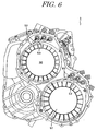
- an inverter connected to an electric motor and a generator is separately arranged from a hybrid drive unit 55 as a vehicle drive unit, and, as shown in Fig. 6 and Fig. 7, the inverter and the hybrid drive unit 55 are connected with a motor lead wire 53 pulled out at a rear cover 52 side, which is opposite side to a side where an output gear 51 of the electric motor 50 is disposed.
- the upper face, side face and the rear cover 52 side of the hybrid drive unit 55 are enlarged for obtaining a space for pulling out the motor lead wire 53.
- the inverter can not be disposed because a terminal for pulling out a motor lead wire disturbs.
- an object of the invention is to provide an enhanced vehicle drive unit.
- a vehicle drive unit obtaining a drive force for driving a vehicle by the drive force of an electric motor comprises the electric motor, a differential unit, a gear unit transmitting a drive force from the electric motor to the differential unit, a cover covering the electric motor, an inverter disposed on the cover, and a lead wire from the electric motor disposed in neighborhood of an output gear of the electric motor, which structures a part of the gear unit, and in a space structured by diameter differences between the output gear and the electric motor, and pulled out to the outside of the cover at a position corresponding to the output gear.
- the electric motor and the inverter are electrically connected through the lead wire.
- an inverter can be disposed on the upper portion of the vehicle drive unit and a rear cover side of the vehicle drive unit is compactly covered.
- the lead wire is structured from a first lead wire, a terminal and a second lead wire, wherein the terminal is disposed in a neighborhood portion of the cover to the output gear by penetrating the cover, the electric motor and the terminal are connected with a first lead wire, and the inverter and the terminal are connected with a second lead wire.
- the lead wire from the electric motor may be a lead wire connected to a stator of the electric motor.
- An inverter case in which the inverter is disposed, may be integrated with the cover, and a grooving space is formed between the rear portion of the cover and the inverter case.
- a heat sink for refrigerating the inverter may be formed in a part of the cover between the inverter and the electric motor.
- a chamfer portion may be formed on the rear portion of the cover corresponding to the rear portion of the electric motor along the outline of the stator of the electric motor.
- a lead wire from the electric motor is disposed in neighborhood of an output gear of the electric motor and in a space structured by diameter differences between the output gear and the electric motor.
- the lead wire is pulled out to the outside of the cover from the space. Therefore, the upper face portion of the electric motor of the vehicle drive unit, which is used as a space for pulling out the lead wire in the conventional unit, is used as a space for disposing the inverter, and the inverter can be disposed on the upper face of the vehicle drive unit, which comparatively has an affording space in the vehicle.
- the vehicle drive unit is compactly structured with the inverter.
- the lead wire is not pulled out from the rear portion of the cover or the rear cover portion. Therefore, the rear cover portion is compactly structured. As a result, interference between the vehicle drive unit and vehicle side members is appreciably prevented during the vehicle drive unit is mounted.
- the terminal which is a comparatively large member, is disposed a neighborhood portion of the cover to the output gear. Therefore, the space structured by the diameter differences between the output gear and the electric motor is effectively used.
- a brushless DC motor can be used as an electric motor, and then, the structure of the vehicle drive unit is simplified.
- the heat sink for refrigerating the inverter is formed at a position corresponding to the rotor portion of the electric motor along with the outline of the rotor. Therefore, the heat sink is formed without futile space.
- a chamfer portion is formed on the rear portion of the cover along the outline of the stator of the electric motor, and the outline of the cover is formed along with the electric motor. Therefore, futile thickness of the rear portion of the cover is prevented, and then, interference with side members of a vehicle is prevented.
- Fig. 1 is a schematic diagram showing an example of a vehicle drive unit
- Fig. 2 is a developed side cross sectional diagram
- Fig. 3 is an elevation of the vehicle drive unit in Fig. 2
- Fig. 4 is a back elevation of the vehicle drive unit in Fig. 2
- Fig. 5 is a partial cross sectional diagram of the vehicle drive unit in Fig, 2.
- An hybrid drive unit 1 as a vehicle drive unit comprises an internal engine 2, a generator 3 structuring a first electric rotation member, a brake unit 4, an electric motor 5 structuring a second electric rotation member, a planetary gear 6, a hydraulic pressure generating unit 7, and a differential unit 9.
- the generator 3, the brake unit 4, the motor 5, the planetary gear 6, the hydraulic pressure generating unit 7 and the differential unit 9 are disposed.
- a first axis A aligned with an engine output shaft 2a, a second axis B structured from a counter shaft 11, a third axis C structured from a motor output shaft 5a, a fourth axis D structured from a drive wheel shafts extending from the differential unit 9 to left and right side and a fifth axis E structured from a drive shaft 8 as a drive member of an oil pump are disposed as shown in Fig. 3. That is, the first axis A, the third axis C and the fourth axis D are disposed so as to surround the second axis B structured from the counter shaft.
- the fifth axis E is disposed under the first axis A and on the side of the fourth axis D.
- Fig. 2 shows the vehicle drive unit, in which the first through fourth axis A, B, C, D are developed.
- an input shaft 13 connected through a flywheel 14 and a damper 12 to the engine output shaft 2a, the generator 3, the brake unit 4 and the planetary gear 6 are disposed.
- the oil pump 7 is connected to the input shaft 13.
- a sun gear S of the planetary gear 6 is connected to a transmission shaft (rotor shaft) 15 transmitting a torque to the generator 3
- a carrier CR supporting the pinions P is connected to the input shaft 13
- a ring gear R is connected to a running rotation shaft 16 structured from a sleeve which is arranged around the input shaft 13.
- the generator 3 comprises a rotor 17 fixed to the transmission shaft 15 and a stator 19 fixed to the cover 10.
- An excitational generator or the like is applicable as the generator 3, however, a magneto generator, such as a blushless DC motor/generator, in which a permanent magnet is used in the rotor, is preferable.
- a rotational position sensor 20 such as a resolver is disposed on a portion of the transmission shaft 15, which penetrates through the rear cover 10c and protrudes therefrom, and correctly detects a rotational position of the rotor for controlling the rotation minutely.
- a counter drive gear 21 for an engine output is fixed to the running rotation shaft 16, a large gear 22 and a small gear 23 are integrally fixed on the counter shaft 11, and the counter drive gear 21 is meshed with the large gear 22.
- a positional relationship of the large gear and the small gear in Fig. 1 is reversed with relationship of them in Fig. 2.
- the electric motor 5 comprises a rotor 25 integrally fixed to the output shaft 5a and a stator 26 fixed to the case 10.
- a DC motor, an induction AC motor or the like are applicable as the electric motor.
- a blushless DC motor having a permanent magnet in the rotor is preferable.
- a rotational position sensor 27 such as a resolver is disposed on a portion of the output shaft 5a, which penetrates through the cover 10 and protrudes therefrom at the opposite side of the motor 5, and correctly detects a rotational position of the rotor 25 for controlling the motor output.
- a counter drive gear 29 for motor output is integrally fixed to the motor output shaft 5a, and the gear 29 is also meshed with the large gear 22 on the counter shaft.
- the differential unit 9 comprises an input gear 31 fixed to a differential case 30.
- the input gear 31 is meshed with the small gear 23 on the counter shaft.
- a center gear 32 which is supported by the differential case, is meshed, with left and right side gears 33l, 33r, separates and transmits an input torque from the input gear 31 to the left and right side gears, then, left and right drive wheel shafts connected to left and right front wheels are driven.
- a cylindrical main cover 10b is disposed at the center position, a front cover 10a is connected to the main cover 10b at the right side in Fig. 5, and a rear cover 10c is connected to the main cover 10b at the left side in Fig. 5.
- the cover 10 is integrally structured from the main cover 10b, the front cover 10a and the rear cover 10c.
- the electric motor 5 is disposed in the main cover 10b.
- first lead wires 35 are connected to the stator including a coil of the electric motor 5. In case of the generator 3, it is same manner.
- the first lead wires 35 are pulled out at a neighborhood portion of the electric motor 5 to the counter drive gear 29 and at a periphery space of the counter drive gear 29.
- the neighborhood portion to the counter drive gear 29 is a portion which is within the axial, i.e. in left-right direction in Fig. 5, length of the gear unit structured from the counter drive gear 29, large gear 22, small gear 23 and the input gear 31 of the differential unit and which is at the radial outer side of the output shaft 5a.
- the counter drive gear 29 of the electric motor 5 is structured from a smaller diameter gear than the large gear 22 on the counter shaft 11 connected to the differential unit 9.
- a dead space is formed around the counter drive gear 29 by the stator 26 of the electric motor 5 having comparatively large diameter and the counter drive gear 29 having smaller diameter. Then, the first lead wires 35 are disposed in the space S, which is surrounding the counter drive gear 29 and is the dead space.
- Six penetrating holes 10f are formed on the center upper portion of the cover 10, which is corresponding to the periphery space S of the counter drive gear 29.
- Six terminals 36 are disposed in the penetrating holes 10f individually.
- the other ends of the first lead wires 35 from the electric motor 5 are individually connected to the three terminals 36 arranged at the left side of Fig. 3, and the other ends of the first lead wires 35 from the generator 3 are individually connected to the three terminals 36 arranged at the right side of Fig. 3.
- a heat sink 10d for refrigerating is formed in the main cover 10b and in the upper portion of Fig. 5 corresponding to the electric motor 5.
- An inverter 37 is disposed on the heat sink 10d.
- First lead wires 39 from the six terminals are connected to terminals 37a of the inverter 37.
- the cover 40 covers the upper portion of the inverter 37.
- a streamlined chamfer portion 10e is formed on the upper portion of the rear cover 10c corresponding to the electric motor 5.
- the streamlined chamfer portion 10e is formed extending to the radial direction from the output shaft 5a and along with the outline of the stator 26.
- a space 43 having a cross section of a triangle groove is formed between an inverter case 41 integrated with the cover 10 and covering the inverter 37 and a periphery portion 10g of the rear cover 10c.
- the hybrid drive unit 1 comprises the aforementioned structure.
- the drive force occurred by the rotation of the electric motor 5 is transmitted through the counter drive gear 29 to the large gear 22 on the counter shaft 11, further outputted through the differential unit 9 to the drive wheel shaft D.
- the output from the engine is transmitted to the input shaft 13, separated by the planetary gear 6 disposed on the same axis with the input shaft 13, then, the output from the engine rotationally drives the generator 3 with necessity, is transmitted to the large gear 22 on the counter shaft 11, and is transmitted through the differential unit 9 to the drive wheel axis D.
- first lead wires 35, connecting the electric motor 5 and the terminals 36 in the cover 10, and the terminals, connecting the first lead wires 35 through the first lead wires 39 to the inverter 37 are disposed in the periphery space S of the counter drive gear 29 of the electric motor 5, that is, in the front dead space of the counter drive gear 29 of the electric motor 5. Therefore, a space for disposing the first lead wires 35 and the terminals 36 is not needed at the rear cover 10c side. As a result, the rear cover 10c can be formed along with the outline of the stator 26 of the electric motor 5.
- first lead wires 35 are not limited to connect to the stators 26, 29 of the electric motor 5 and the generator 3, the first lead wires 35 can be connected to the rotors 25, 17 according to the motor structure.
- the disposing form of the first lead wires 35 and the terminals 36 is arbitrary as long as they are disposed in a neighborhood position to the counter drive gear 29 as the output gear and in the dead space formed by the diameter differences between the output gear and the electric motor. Therefore, an appropriate cable supporting portion such as grooves can be formed in the cover 10 for supporting the lead wires.
- the invention is described with a vehicle drive unit comprising an electric motor of a hybrid vehicle obtaining a drive force from an electric motor and an internal engine.
- the invention is not limited to a hybrid vehicle, and applicable to a vehicle drive unit of an electric vehicle obtaining a drive force from only electric motor.
- An inverter 37 is disposed on a cover 10, lead wires 35, 39 from an electric motor 5 are disposed at a neighborhood position to an output gear 29 in a dead space formed by diameter differences between the output gear 29 and the motor 5, and the lead wires 35, 39 are pulled out to the outside of the cover 10 at a position corresponding to the output gear portion.
- An upper side portion of the electric motor 5, which is used as a space for pulling out the lead wires 35, 39 in the conventional unit, can be used as a space for disposing the inverter 37. That is, the inverter 37 can be disposed at the upper side of the vehicle drive unit, which comparatively has affording space. As a result, the vehicle drive unit and the inverter 37 are disposed in compact. [Fig. 5]
- An inverter (37) is disposed on a cover (10), lead wires (35, 39) from an electric motor (5) are disposed at a neighborhood position to an output gear (29) in a dead space formed by diameter differences between the output gear (29) and the motor (5), and the lead wires (35, 39) are pulled out to the outside of the cover (10) at a position corresponding to the output gear portion.
- An upper side portion of the electric motor (5) which is used as a space for pulling out the lead wires (35, 39) in the conventional unit, can be used as a space for disposing the inverter (37). That is, the inverter (37) can be disposed at the upper side of the vehicle drive unit, which comparatively has affording space. As a result, the vehicle drive unit and the inverter (37) are disposed in compact. [Fig. 5]
Abstract
Description
[Fig. 5]
[Fig. 5]
Claims (6)
- A vehicle drive unit obtaining a drive force for driving a vehicle by the drive force of an electric motor (5) comprising:the electric motor (5);a differential unit (9);a gear unit (22, 23, 29, 31) transmitting a drive force from the electric motor (5) to the differential unit (9);a cover (10) covering the electric motor (5);an inverter (37) disposed on the cover (10); anda lead wire (35, 39) from the electric motor (5) disposed in neighborhood of an output gear (29) of the electric motor (5), which structures a part of the gear unit (22, 23, 29, 31), and in a space (S) structured by diameter differences between the output gear (29) and the electric motor (5), and pulled out to the outside of the cover (10) at a position corresponding to the output gear (29);
wherein the electric motor (5) and the inverter (37) are electrically connected through the lead wire (35, 39). - A vehicle drive unit according to claim 1, wherein the lead wire is structured from a first lead wire (35), a terminal (36) and a second lead wire (39), wherein the terminal (36) is disposed in a neighborhood portion of the cover (10) to the output gear (29) by penetrating the cover (10), the electric motor (5) and the terminal (36) are connected with said first lead wire (35), and the inverter (37) and the terminal (36) are connected with said second lead wire (39).
- A vehicle drive unit according to claim 2, wherein the first lead wire (35) from the electric motor (5) is a lead wire connected to a stator (26) of the electric motor (5).
- A vehicle drive unit according to any of claims 1 to 3, wherein an inverter case (41), in which the inverter (37) is disposed, is integrated with the cover (10), and a grooving space (42) is formed between the rear portion (10c) of the cover (10) and the inverter case (41).
- A vehicle drive unit according to any of claims 1 to 4, wherein a chamfer portion (10e) is formed on the rear portion (10c) of the cover (10) corresponding to the rear portion of the electric motor (5) along the outline of the stator (26) of the electric motor (5).
- The vehicle drive unit according to any of claims 1 to 6, wherein a heat sink (10d) for refrigerating the inverter (37) is formed in a part of the cover (10) between the inverter (37) and the electric motor (5).
Applications Claiming Priority (2)
| Application Number | Priority Date | Filing Date | Title |
|---|---|---|---|
| JP29556699 | 1999-10-18 | ||
| JP29556699A JP3893815B2 (en) | 1999-10-18 | 1999-10-18 | Vehicle drive device |
Publications (2)
| Publication Number | Publication Date |
|---|---|
| EP1093958A2 true EP1093958A2 (en) | 2001-04-25 |
| EP1093958A3 EP1093958A3 (en) | 2005-06-08 |
Family
ID=17822309
Family Applications (1)
| Application Number | Title | Priority Date | Filing Date |
|---|---|---|---|
| EP00122632A Withdrawn EP1093958A3 (en) | 1999-10-18 | 2000-10-17 | Vehicle drive unit |
Country Status (4)
| Country | Link |
|---|---|
| US (1) | US6533696B1 (en) |
| EP (1) | EP1093958A3 (en) |
| JP (1) | JP3893815B2 (en) |
| KR (1) | KR100651161B1 (en) |
Cited By (6)
| Publication number | Priority date | Publication date | Assignee | Title |
|---|---|---|---|---|
| WO2003021747A1 (en) * | 2001-09-03 | 2003-03-13 | Honda Giken Kogyo Kabushiki Kaisha | Wiring structure of hybrid vehicle motor |
| FR2854283A1 (en) * | 2003-04-23 | 2004-10-29 | Mitsubishi Electric Corp | Automotive electric motor-generator apparatus for hybrid vehicle, has inverter unit installed in close proximity to rotary electric machine, and AC and DC wirings electrically connecting machine and battery respectively to unit |
| WO2008011958A1 (en) * | 2006-07-22 | 2008-01-31 | Daimler Ag | Motor vehicle |
| CN104626953A (en) * | 2013-11-08 | 2015-05-20 | 株式会社Vctech | Integrated electric power system used for electric vehicle |
| CN105216598A (en) * | 2015-09-28 | 2016-01-06 | 蔚来汽车有限公司 | A kind of power drive system of automobile and employ the automobile of this power drive system |
| WO2022053748A1 (en) * | 2020-09-11 | 2022-03-17 | Psa Automobiles Sa | Electrical connection system |
Families Citing this family (21)
| Publication number | Priority date | Publication date | Assignee | Title |
|---|---|---|---|---|
| JP3558277B2 (en) * | 2000-03-22 | 2004-08-25 | ジヤトコ株式会社 | Transmission unit for hybrid vehicle |
| JP3603889B2 (en) * | 2002-10-25 | 2004-12-22 | 日産自動車株式会社 | Hybrid transmission |
| JP4243954B2 (en) * | 2002-12-27 | 2009-03-25 | アイシン・エィ・ダブリュ株式会社 | Vibration control device for electric drive control unit |
| US7357203B2 (en) * | 2004-09-28 | 2008-04-15 | Oshkosh Truck Corporation | Self-contained axle module |
| US8561735B2 (en) * | 2004-09-28 | 2013-10-22 | Oshkosh Corporation | Self-contained axle module |
| US7448460B2 (en) * | 2004-09-28 | 2008-11-11 | Oshkosh Corporation | Power takeoff for an electric vehicle |
| JP4650691B2 (en) * | 2006-03-03 | 2011-03-16 | 住友電装株式会社 | Electrical connection structure |
| US8585526B2 (en) | 2007-06-18 | 2013-11-19 | American Axle & Manufacturing, Inc. | Vehicle driveline component having heat sink for increased heat rejection capabilities |
| US7819769B2 (en) * | 2007-06-18 | 2010-10-26 | American Axle & Manufacturing, Inc. | Vehicle driveline component having heat sink for increased heat rejection capabilities |
| JP2011062023A (en) | 2009-09-11 | 2011-03-24 | Aisin Aw Co Ltd | Electrical connection device |
| JP5721332B2 (en) * | 2010-03-05 | 2015-05-20 | 矢崎総業株式会社 | Inverter terminal block installed in the motor case |
| JP5632225B2 (en) * | 2010-07-30 | 2014-11-26 | 矢崎総業株式会社 | Terminal connection structure |
| DE102011006281A1 (en) * | 2011-03-29 | 2012-10-04 | Zf Friedrichshafen Ag | Electric machine of electric drive strand for hybrid vehicle powertrain, has component element that is firmly connected with rotor shaft by which component element is rotated along axial direction |
| US8646563B2 (en) * | 2012-03-21 | 2014-02-11 | Deere & Company | Work machine with compact generator and hydraulic drive assembly |
| JP5862502B2 (en) * | 2012-07-27 | 2016-02-16 | アイシン・エィ・ダブリュ株式会社 | Vehicle drive device |
| US9391496B2 (en) * | 2013-01-18 | 2016-07-12 | GM Global Technology Operations LLC | Transmission for a vehicle |
| US9120389B1 (en) * | 2014-02-08 | 2015-09-01 | Atieva, Inc. | Integrated motor assembly with compliantly mounted power inverter |
| WO2015188826A1 (en) * | 2014-06-13 | 2015-12-17 | Schaeffler Technologies AG & Co. KG | Hybrid module designed as an insertable module |
| US9283837B1 (en) * | 2015-01-28 | 2016-03-15 | Atieva, Inc. | Compliantly mounted motor assembly utilizing dual levels of vibration isolation |
| CN112075013B (en) * | 2018-04-25 | 2023-08-18 | 日本电产株式会社 | Motor unit and method for manufacturing motor unit |
| US11223305B2 (en) * | 2018-11-16 | 2022-01-11 | Toyota Jidosha Kabushiki Kaisha | Vehicle driving device |
Citations (2)
| Publication number | Priority date | Publication date | Assignee | Title |
|---|---|---|---|---|
| JPH09182352A (en) * | 1995-12-26 | 1997-07-11 | Aisin Aw Co Ltd | Motor drive |
| JPH11180163A (en) * | 1997-12-18 | 1999-07-06 | Honda Motor Co Ltd | Electric vehicle |
Family Cites Families (9)
| Publication number | Priority date | Publication date | Assignee | Title |
|---|---|---|---|---|
| WO1988006107A1 (en) * | 1987-02-18 | 1988-08-25 | Hino Jidosha Kogyo Kabushiki Kaisha | Electric braking and auxiliary acceleration apparatus for automotive vehicles |
| JP2967103B2 (en) * | 1993-05-24 | 1999-10-25 | 株式会社エクォス・リサーチ | Hybrid vehicle |
| US5744895A (en) * | 1995-01-31 | 1998-04-28 | Nippondenso Co., Ltd. | System for driving electric vehicles |
| JP3173319B2 (en) * | 1995-04-28 | 2001-06-04 | 株式会社エクォス・リサーチ | Hybrid vehicle |
| US6018694A (en) * | 1996-07-30 | 2000-01-25 | Denso Corporation | Controller for hybrid vehicle |
| JP3661288B2 (en) * | 1996-08-05 | 2005-06-15 | 株式会社エクォス・リサーチ | Hybrid type vehicle |
| JP3891533B2 (en) * | 1998-11-16 | 2007-03-14 | アイシン・エィ・ダブリュ株式会社 | Drive device |
| JP3886697B2 (en) * | 1999-04-27 | 2007-02-28 | アイシン・エィ・ダブリュ株式会社 | Drive device |
| JP3886696B2 (en) * | 1999-04-27 | 2007-02-28 | アイシン・エィ・ダブリュ株式会社 | Drive device |
-
1999
- 1999-10-18 JP JP29556699A patent/JP3893815B2/en not_active Expired - Lifetime
-
2000
- 2000-10-17 KR KR1020000061072A patent/KR100651161B1/en active IP Right Grant
- 2000-10-17 EP EP00122632A patent/EP1093958A3/en not_active Withdrawn
- 2000-10-18 US US09/690,874 patent/US6533696B1/en not_active Expired - Lifetime
Patent Citations (3)
| Publication number | Priority date | Publication date | Assignee | Title |
|---|---|---|---|---|
| JPH09182352A (en) * | 1995-12-26 | 1997-07-11 | Aisin Aw Co Ltd | Motor drive |
| JPH11180163A (en) * | 1997-12-18 | 1999-07-06 | Honda Motor Co Ltd | Electric vehicle |
| US6220380B1 (en) * | 1997-12-18 | 2001-04-24 | Honda Giken Kogyo Kabushiki Kaisha | Electric vehicle with battery box arrangement |
Cited By (14)
| Publication number | Priority date | Publication date | Assignee | Title |
|---|---|---|---|---|
| US7193344B2 (en) | 2001-09-03 | 2007-03-20 | Honda Motor Co., Ltd. | Wiring structure of hybrid vehicle motor |
| WO2003021747A1 (en) * | 2001-09-03 | 2003-03-13 | Honda Giken Kogyo Kabushiki Kaisha | Wiring structure of hybrid vehicle motor |
| AU2002332237B2 (en) * | 2001-09-03 | 2005-06-09 | Honda Giken Kogyo Kabushiki Kaisha | Wiring structure of hybrid vehicle motor |
| AU2002332237B9 (en) * | 2001-09-03 | 2005-07-14 | Honda Giken Kogyo Kabushiki Kaisha | Wiring structure of hybrid vehicle motor |
| US7610973B2 (en) | 2003-04-23 | 2009-11-03 | Mitsubishi Denki Kabushiki Kaisha | Automotive electric motor-generator apparatus |
| FR2854283A1 (en) * | 2003-04-23 | 2004-10-29 | Mitsubishi Electric Corp | Automotive electric motor-generator apparatus for hybrid vehicle, has inverter unit installed in close proximity to rotary electric machine, and AC and DC wirings electrically connecting machine and battery respectively to unit |
| WO2008011958A1 (en) * | 2006-07-22 | 2008-01-31 | Daimler Ag | Motor vehicle |
| US8857543B2 (en) | 2006-07-22 | 2014-10-14 | Daimler A.G. | Motor vehicle |
| CN104626953A (en) * | 2013-11-08 | 2015-05-20 | 株式会社Vctech | Integrated electric power system used for electric vehicle |
| CN104626953B (en) * | 2013-11-08 | 2018-01-09 | 株式会社Vctech | Electric vehicles integrated electric Force system |
| CN105216598A (en) * | 2015-09-28 | 2016-01-06 | 蔚来汽车有限公司 | A kind of power drive system of automobile and employ the automobile of this power drive system |
| US10988013B2 (en) | 2015-09-28 | 2021-04-27 | Nio (Anhui) Holding Co., Ltd. | Electric drive system for motor vehicle and motor vehicle using same |
| WO2022053748A1 (en) * | 2020-09-11 | 2022-03-17 | Psa Automobiles Sa | Electrical connection system |
| FR3114052A1 (en) * | 2020-09-11 | 2022-03-18 | Psa Automobiles Sa | ELECTRICAL CONNECTION SYSTEM |
Also Published As
| Publication number | Publication date |
|---|---|
| EP1093958A3 (en) | 2005-06-08 |
| US6533696B1 (en) | 2003-03-18 |
| KR100651161B1 (en) | 2006-11-28 |
| JP3893815B2 (en) | 2007-03-14 |
| KR20010051080A (en) | 2001-06-25 |
| JP2001119810A (en) | 2001-04-27 |
Similar Documents
| Publication | Publication Date | Title |
|---|---|---|
| EP1093958A2 (en) | Vehicle drive unit | |
| US7975571B2 (en) | Hybrid drive device | |
| US8142317B2 (en) | Power transmission apparatus of hybrid vehicle | |
| JP3656841B2 (en) | Drive unit with electric motor | |
| US7259493B2 (en) | Stator of two rotor single stator type electric motor | |
| US7239033B2 (en) | Drive apparatus for hybrid vehicle | |
| US20120242198A1 (en) | Vehicle drive device | |
| JP3660460B2 (en) | Electric bicycle drive device | |
| US6092985A (en) | Connection for a torque converter | |
| JP7216195B2 (en) | Engine and motor assemblies and vehicle drives | |
| US8973456B2 (en) | Fitting structure | |
| WO2017170081A1 (en) | Hybrid car and vehicle | |
| JP2944815B2 (en) | Electric vehicle drive | |
| JP4406883B2 (en) | Drive device for hybrid vehicle | |
| JP2004153895A (en) | Electric motor for vehicle | |
| CN110912337A (en) | Vehicle driving motor with built-in planet row speed reduction unit | |
| EP1419920B1 (en) | Hybrid transmission | |
| JP6365576B2 (en) | Hybrid vehicles and vehicles | |
| JP6365577B2 (en) | Hybrid vehicles and vehicles | |
| CN211508826U (en) | Integrated motor driving system for dual-output vehicle | |
| CN113335082A (en) | Vehicle drive device | |
| JPH07143696A (en) | Motor | |
| US20120049675A1 (en) | Electric power generating differential | |
| JP2004058700A (en) | Drive unit for electric automobile | |
| EP3713054A1 (en) | Motor for vehicle |
Legal Events
| Date | Code | Title | Description |
|---|---|---|---|
| PUAI | Public reference made under article 153(3) epc to a published international application that has entered the european phase |
Free format text: ORIGINAL CODE: 0009012 |
|
| AK | Designated contracting states |
Kind code of ref document: A2 Designated state(s): AT BE CH CY DE DK ES FI FR GB GR IE IT LI LU MC NL PT SE |
|
| AX | Request for extension of the european patent |
Free format text: AL;LT;LV;MK;RO;SI |
|
| PUAL | Search report despatched |
Free format text: ORIGINAL CODE: 0009013 |
|
| AK | Designated contracting states |
Kind code of ref document: A3 Designated state(s): AT BE CH CY DE DK ES FI FR GB GR IE IT LI LU MC NL PT SE |
|
| AX | Request for extension of the european patent |
Extension state: AL LT LV MK RO SI |
|
| RIC1 | Information provided on ipc code assigned before grant |
Ipc: 7H 02K 11/04 B Ipc: 7H 02K 5/22 B Ipc: 7B 60L 11/12 A Ipc: 7B 60K 6/04 B |
|
| 17P | Request for examination filed |
Effective date: 20050901 |
|
| AKX | Designation fees paid |
Designated state(s): DE FR GB IT |
|
| 17Q | First examination report despatched |
Effective date: 20130523 |
|
| STAA | Information on the status of an ep patent application or granted ep patent |
Free format text: STATUS: THE APPLICATION IS DEEMED TO BE WITHDRAWN |
|
| 18D | Application deemed to be withdrawn |
Effective date: 20171024 |
|
| RIC1 | Information provided on ipc code assigned before grant |
Ipc: B60K 6/04 20060101ALI20050418BHEP Ipc: H02K 5/22 20060101ALI20050418BHEP Ipc: B60L 11/12 20060101AFI20010209BHEP Ipc: H02K 11/04 20160101ALI20050418BHEP |