WO2020203333A1 - 光ファイバ表示システム及び光ファイバ切替方法 - Google Patents
光ファイバ表示システム及び光ファイバ切替方法 Download PDFInfo
- Publication number
- WO2020203333A1 WO2020203333A1 PCT/JP2020/012212 JP2020012212W WO2020203333A1 WO 2020203333 A1 WO2020203333 A1 WO 2020203333A1 JP 2020012212 W JP2020012212 W JP 2020012212W WO 2020203333 A1 WO2020203333 A1 WO 2020203333A1
- Authority
- WO
- WIPO (PCT)
- Prior art keywords
- optical fiber
- identification number
- communication device
- acquired
- control terminal
- Prior art date
- Legal status (The legal status is an assumption and is not a legal conclusion. Google has not performed a legal analysis and makes no representation as to the accuracy of the status listed.)
- Ceased
Links
Images












Classifications
-
- H—ELECTRICITY
- H04—ELECTRIC COMMUNICATION TECHNIQUE
- H04B—TRANSMISSION
- H04B10/00—Transmission systems employing electromagnetic waves other than radio-waves, e.g. infrared, visible or ultraviolet light, or employing corpuscular radiation, e.g. quantum communication
- H04B10/07—Arrangements for monitoring or testing transmission systems; Arrangements for fault measurement of transmission systems
- H04B10/075—Arrangements for monitoring or testing transmission systems; Arrangements for fault measurement of transmission systems using an in-service signal
- H04B10/079—Arrangements for monitoring or testing transmission systems; Arrangements for fault measurement of transmission systems using an in-service signal using measurements of the data signal
- H04B10/0795—Performance monitoring; Measurement of transmission parameters
-
- H—ELECTRICITY
- H04—ELECTRIC COMMUNICATION TECHNIQUE
- H04B—TRANSMISSION
- H04B10/00—Transmission systems employing electromagnetic waves other than radio-waves, e.g. infrared, visible or ultraviolet light, or employing corpuscular radiation, e.g. quantum communication
- H04B10/27—Arrangements for networking
- H04B10/272—Star-type networks or tree-type networks
-
- H—ELECTRICITY
- H04—ELECTRIC COMMUNICATION TECHNIQUE
- H04Q—SELECTING
- H04Q11/00—Selecting arrangements for multiplex systems
- H04Q11/0001—Selecting arrangements for multiplex systems using optical switching
- H04Q11/0062—Network aspects
- H04Q11/0067—Provisions for optical access or distribution networks, e.g. Gigabit Ethernet Passive Optical Network (GE-PON), ATM-based Passive Optical Network (A-PON), PON-Ring
-
- G—PHYSICS
- G02—OPTICS
- G02B—OPTICAL ELEMENTS, SYSTEMS OR APPARATUS
- G02B6/00—Light guides; Structural details of arrangements comprising light guides and other optical elements, e.g. couplings
- G02B6/24—Coupling light guides
- G02B6/26—Optical coupling means
- G02B6/28—Optical coupling means having data bus means, i.e. plural waveguides interconnected and providing an inherently bidirectional system by mixing and splitting signals
- G02B6/2804—Optical coupling means having data bus means, i.e. plural waveguides interconnected and providing an inherently bidirectional system by mixing and splitting signals forming multipart couplers without wavelength selective elements, e.g. "T" couplers, star couplers
- G02B6/2852—Optical coupling means having data bus means, i.e. plural waveguides interconnected and providing an inherently bidirectional system by mixing and splitting signals forming multipart couplers without wavelength selective elements, e.g. "T" couplers, star couplers using tapping light guides arranged sidewardly, e.g. in a non-parallel relationship with respect to the bus light guides (light extraction or launching through cladding, with or without surface discontinuities, bent structures)
-
- G—PHYSICS
- G02—OPTICS
- G02B—OPTICAL ELEMENTS, SYSTEMS OR APPARATUS
- G02B6/00—Light guides; Structural details of arrangements comprising light guides and other optical elements, e.g. couplings
- G02B6/24—Coupling light guides
- G02B6/42—Coupling light guides with opto-electronic elements
- G02B6/4201—Packages, e.g. shape, construction, internal or external details
- G02B6/4202—Packages, e.g. shape, construction, internal or external details for coupling an active element with fibres without intermediate optical elements, e.g. fibres with plane ends, fibres with shaped ends, bundles
- G02B6/4203—Optical features
-
- G—PHYSICS
- G02—OPTICS
- G02B—OPTICAL ELEMENTS, SYSTEMS OR APPARATUS
- G02B6/00—Light guides; Structural details of arrangements comprising light guides and other optical elements, e.g. couplings
- G02B6/24—Coupling light guides
- G02B6/42—Coupling light guides with opto-electronic elements
- G02B6/4201—Packages, e.g. shape, construction, internal or external details
- G02B6/4219—Mechanical fixtures for holding or positioning the elements relative to each other in the couplings; Alignment methods for the elements, e.g. measuring or observing methods especially used therefor
-
- H—ELECTRICITY
- H04—ELECTRIC COMMUNICATION TECHNIQUE
- H04Q—SELECTING
- H04Q11/00—Selecting arrangements for multiplex systems
- H04Q11/0001—Selecting arrangements for multiplex systems using optical switching
- H04Q11/0062—Network aspects
- H04Q2011/0079—Operation or maintenance aspects
- H04Q2011/0083—Testing; Monitoring
Definitions
- the present disclosure relates to an optical fiber display system used for optical cable switching work and an optical fiber switching method thereof.
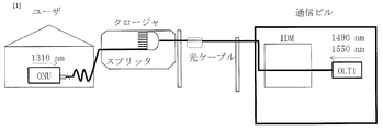
- the optical access network provides users with Internet and telephone services by providing the equipment shown in Fig. 1.
- An optical subscriber line termination device (Optical Line Thermal: OLT), which is a communication device, is installed in a communication building, and an optical subscriber line network device (Optical Network Unit: ONU) is installed in the user's home.
- OLT and ONU are connected by an IDM, an optical cable, and a splitter.
- IDM optical data management
- the OLT and ONU recognize each other and provide users with high-speed broadband services such as the Internet and telephone. ..
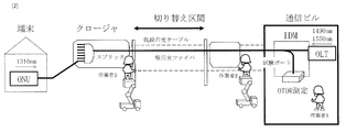
- Non-Patent Document 1 In addition to communication equipment including optical cables, social infrastructure equipment such as roads, electricity, gas, water supply, and railway companies have been constructed. If the optical cable interferes with the construction of social infrastructure equipment, the route of the optical cable must be changed in advance. The route change is shown in FIGS. 2 to 4. Cut the optical cable fiber that provides the current service at two points and replace it with a new optical cable fiber. By cutting two optical fibers in this way and connecting them to a new cable, the area that hinders the construction is bypassed (Non-Patent Document 1).
- a large number of optical fibers are included in the optical fiber cable. Cutting the optical cable and moving it to a new route means selecting the optical fiber in the cable without mistake and connecting it to the optical fiber in the new optical cable.
- This worker 1 is in a position to monitor the entire construction.
- the worker 1 carries out a pulse test (Optical Time Domain Reflectometer: OTDR).
- OTDR Optical Time Domain Reflectometer
- This pulse test is a test device that outputs a wavelength of 1650 nm from an OTDR measuring device installed in a communication building and monitors the state of an optical fiber extending from the communication building in real time.
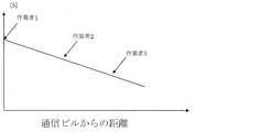
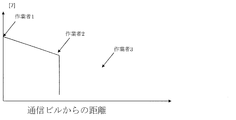
- FIGS. 2 to 9. 2 to 4 show the whole process
- FIGS. 5 to 9 show changes in the waveform of the OTDR measurement with respect to the process.
- the worker 1 carries out the OTDR test in the state of FIG. This test is a test in which a wavelength of 1650 nm is propagated from a communication building to an optical fiber (Non-Patent Document 2).
- FIG. 5 is a waveform of the OTDR measurement screen.
- the worker 3 confirms that the test wavelength has been reached, and then the worker 2 confirms that the test wavelength has also been reached (Fig. 2).
- the three workers are cooperating with each other using mobile phones or the like.
- the worker 3 cuts the optical fiber (FIG. 3). By cutting the optical fiber, a change in waveform appears on the measurement screen of the OTDR as shown in FIG. 6, and the worker 1 in the communication building confirms that the worker 3 has cut the optical fiber.
- the worker 2 cuts the optical fiber (FIG. 2), and a change appears in the waveform of the OTDR measurement screen (FIG. 7). In this way, the optical fiber is identified and cut without mistake.
- connection of the new optical fiber is carried out by the worker 2 first (Fig. 4), and the worker 1 confirms from the waveform change on the OTDR measurement screen (Fig. 8). Then, the worker 3 connects the newly installed optical fiber (FIG. 4), and the worker 1 also confirms from the waveform change on the measurement screen of the OTDR (FIG. 9). Finally, the worker 1 confirms the communication between the OLT and the ONU, and completes the switching of the optical fiber.
- the work to transfer the existing optical fiber to the new optical fiber is being carried out outside the communication building.
- the confirmation work and the instruction are given by the worker 1 in the communication building, and the workers 2 and 3 are in contact with each other to carry out the work.
- the conventional optical fiber switching work has a problem of inefficiency because the work is performed while the workers are in contact with each other.
- the purpose of this patent is to provide an optical fiber display system and an optical fiber switching method capable of efficiently performing optical fiber switching work.
- the present invention uses a terminal that can confirm the confirmation work for switching the optical fiber at the construction site, and does not assign a worker to the communication building.
- the optical fiber display system is an optical fiber display system including a plurality of core wire control terminals.
- the core wire control terminal is A bending forming portion that forms a bend at an arbitrary position of the optical fiber and leaks an optical signal propagating through the optical fiber from the bending.
- An analysis unit that acquires the identification numbers of communication devices connected to both ends of the optical fiber included in the leaked optical signal, and an analysis unit.
- the communication unit that queries the database that stores the relationship between the optical fiber and the communication device for the acquired identification number of the communication device, and receives the identification number of the optical fiber corresponding to the acquired identification number of the communication device from the database.
- a display unit that displays the acquired identification number of the communication device and the received identification number of the optical fiber, and It is characterized by having.
- a worker leaks an optical signal from a communication device from an optical fiber using a core wire control terminal at one cutting point of the optical fiber, and an identification number such as a MAC address is generated from the optical signal. To confirm. By confirming this identification number, it is possible to identify the optical fiber to be switched without allocating a worker to the communication building. Further, at other cut points of the optical fiber, the worker similarly confirms the identification number such as the MAC address using the core wire control terminal. Then, by sharing this information with each other, the optical fiber to be switched can be identified, disconnected, and connected without the worker in the communication building.
- a specific optical fiber switching method is to use an optical access network that connects an optical network unit (OLT) and an optical subscriber line network unit (Optical Network Unit: ONU) with an optical fiber.
- This is an optical fiber switching method for switching a part of an optical fiber from an existing optical fiber to a new optical fiber.
- the identification numbers of the OLT and the ONU communication device are acquired by using a core wire control terminal at both ends of the partial section, and the acquired communication.
- the device identification number is queried in a database that stores the relationship between the optical fiber, the OLT, and the ONU, and the optical fiber identification number corresponding to the acquired communication device identification number is the current optical fiber to be switched.
- the end on the ONU side is cut first among both ends of the partial section, and the core wire control terminal on the OLT side is connected to the communication device of the ONU.
- a cutting step of cutting the end on the OLT side after the identification number is not displayed, and An information update step of updating information in the database, wherein the identification number of the optical fiber in the database is rewritten from the identification number of the current optical fiber to the identification number of the newly installed optical fiber.
- the OLT-side communication device is connected to the OLT-side core wire control terminal by first connecting to the OLT-side end of both ends of the partial section.
- the connection process of connecting to the end on the ONU side and the confirmation step performed after connecting the new optical fiber the identification numbers of the communication devices of the OLT and the ONU are acquired by using the core wire control terminal at both ends of the partial section, and the acquired communication is performed.
- the present invention can provide an optical fiber display system and an optical fiber switching method capable of efficiently performing optical fiber switching work.
- the core wire control terminal of the optical fiber display system further has a position information acquisition unit for grasping its own position, and the communication unit of the core wire control terminal is the communication device.
- the identification number, the identification number of the optical fiber, and the grasped position of the optical fiber are notified to each other, and the display unit of the core wire control terminal is a communication device notified from the other core wire control terminal. It is characterized in that the identification number, the identification number of the optical fiber, and the position of the other core wire control terminal are also displayed.
- the analysis unit of the core wire control terminal provided in the optical fiber display system causes the display unit to hide the identification number of the communication device when the leaked optical signal disappears.
- the communication unit is made to make an inquiry again to receive the identification number of the optical fiber corresponding to the newly acquired identification number of the communication device from the database.
- the display unit is characterized in that the newly acquired identification number of the communication device and the received identification number of the optical fiber are displayed.
- the analysis unit of the core wire control terminal of the optical fiber display system acquires the authentication information transmitted by the communication device included in the leaked optical signal, and the display unit acquires the acquired communication device.
- the authentication information acquired together with the identification number of the optical fiber and the identification number of the received optical fiber may also be displayed.
- the authentication information from the ONU can also be acquired and confirmed by the core wire control terminal.
- the communication unit of the core wire control terminal included in the optical fiber display system according to the present invention transmits a correction signal for correcting the relationship between the optical fiber stored in the database and the communication device to the database.
- a registration step of registering the position information obtained by cutting the working optical fiber in the cutting step, the identification number of the communication device acquired in the confirmation step, and the authentication information in the database can be further performed.
- the present invention can provide an optical fiber display system and an optical fiber switching method capable of efficiently performing optical fiber switching work.
- the present invention provides a method in which no worker is assigned to the communication building in order to improve work efficiency. Specifically, the communication light output from the OLT and the communication light output from the ONU are used.
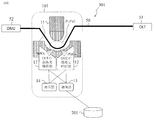
- FIG. 10 is a diagram illustrating the optical fiber display system 301 of the present embodiment.
- the optical fiber display system 301 is an optical fiber display system including a plurality of core wire control terminals 101.
- the core line control terminal 101 is A bending forming portion 11 that forms a bend at an arbitrary position of the optical fiber 50 and leaks an optical signal propagating through the optical fiber 50 from the bending.
- the optical fiber display system 301 includes two core wire control terminals 101 as described in FIGS. 14 and 14, but in FIGS. 10 to 13, only one core wire control terminal 101 is displayed for explanation. There is.
- the communication light output from the OLT 51 and the ONU 52 includes a MAC address (Media Access Control address: hereinafter abbreviated as the MAC address) that is a unique identification number assigned to each. Efficient construction can be performed by acquiring the MAC address at the construction site where the optical fiber is cut and connected. In this embodiment, a method of acquiring a MAC address will be described.
- MAC address Media Access Control address: hereinafter abbreviated as the MAC address
- the OLT 51 and ONU 52 are connected to both ends of the optical fiber 50, and the OLT 51 and ONU 52 are communicating with each other.
- the core wire control terminal 101 is arranged at a desired position of the optical fiber 50.
- the optical fiber 50 is bent by sandwiching the optical fiber 50 between the concave and convex bending forming portions 11. In the bent optical fiber 50, the communication light of the OLT 51 and the ONU 52 leaks separately from the bent portion.
- the analysis unit 12 acquires the leaked light and analyzes it.
- An avalanche photodiode (abbreviated as APD), which is a type of photodiode, is used in the analysis unit 12. This is because the communication light is high speed, and the signal cannot be analyzed if it is a low speed photodiode.
- the analysis unit 12 converts an optical signal into an electric signal by APD, extracts only the MAC address information from the electric signal, and displays the MAC address on the display unit 14.
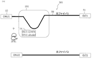
- (Embodiment 2) 11 to 13 are views for explaining the present embodiment. As described in the first embodiment, it is assumed that the optical fiber 50 is bent to acquire the MAC addresses of the OLT 51 and the ONU 52. However, since the MAC address displayed on the display unit 14 is a list of numerical values, the operator cannot determine whether or not the optical fiber is the target of switching work just by looking at it.
- the communication unit 13 that communicates with the database 201 that manages the optical access network is used.
- the communication unit 13 is, for example, a tablet terminal that can be carried by an operator.
- wireless communication can be performed between the core line control terminal 101, the communication unit 13, and the database 201.
- the core wire control terminal 101 acquires the MAC addresses of the OLT 51 and the ONU 52.
- the MAC address of the OLT51 is 123456
- the MAC address of the ONU52 is abcdef.
- the tablet queries the database 201 for this information.
- Database 201 manages the MAC addresses of OLT and ONU connected to each optical fiber, the number of connection points, the length of the optical fiber, and the like.
- the optical fiber number corresponding to the MAC address is transmitted from the database 201 to the tablet.
- the tablet displays the optical fiber number on the screen. For example, the displayed optical fiber number is 1.
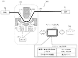
- the worker can recognize the number of the currently selected optical fiber as shown in FIG.
- the worker starts the construction after confirming that the number matches the optical fiber number specified in the construction instruction sheet or the like. Therefore, the optical fiber to be constructed can be confirmed only by the on-site worker without allocating the worker of the communication building.
- FIG. 14 is a diagram illustrating the present embodiment. It is shown in FIGS. 2 to 4 that the switching work of the optical fiber 50 is performed at two places other than the communication building. The worker 2 and the worker 3 are separated into two places, each of which cuts and connects the optical fiber 50. Both have to work on the correct optical fiber 50. That is, the worker 3 is not allowed to cut an optical fiber different from the optical fiber cut by the worker 2. Therefore, a mechanism that can share both information is required. Therefore, the tablet has the following two new functions. (1) GPS function (2) A function that recognizes tablets and displays the same information on multiple tablets.
- the core wire control terminal further has a position information acquisition unit for grasping its own position.
- the communication unit of the core wire control terminal notifies each other of the identification number of the communication device, the identification number of the optical fiber, and the grasped position of itself.
- the display unit of the core wire control terminal also displays the identification number of the communication device, the identification number of the optical fiber, and the position of the other core wire control terminal notified from the other core wire control terminal. It is characterized by that.
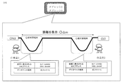
- two workers (worker 2 and worker 3), both of which use the core wire control terminal 101, acquire the MAC address information of the OLT 51 and the ONU 52, and further use the tablet (communication unit 13) to acquire the MAC address information of the database 201.
- FIG. 15 will be further described.
- the two workers bend the optical fiber 50 to acquire the MAC addresses of the ONU 52 and the OLT 51, and acquire the optical fiber numbers from the database.
- Each tablet displays information for the two workers on the screen. Further, the tablet grasps each other's positions by using the GPS function, and displays the distance between the worker 2 and the worker 3 on the screen.
- This optical fiber switching method is an optical fiber switching method in which a part of the optical fiber is switched from an existing optical fiber to a new optical fiber in an optical access network connecting an OLT and an ONU with an optical fiber.
- a specific process for identifying the active optical fiber to be switched, and The cutting step of cutting the working optical fiber and The information update process for updating the information in the database, and The connection process for connecting the new optical fiber and The confirmation process performed after connecting the new optical fiber and It is characterized by performing.
- an identification number of the communication device of the OLT and the ONU is acquired by using a core wire control terminal, and the acquired identification number of the communication device is used as an optical fiber, an OLT, and the like.
- the database for storing the ONU relationship is inquired, and it is confirmed by the core wire control terminal that the identification number of the optical fiber corresponding to the acquired identification number of the communication device is the working optical fiber to be switched.
- the end on the ONU side is cut first among both ends of the partial section, and the identification number of the communication device of the ONU is not displayed on the core wire control terminal on the OLT side. Later, the end on the OLT side is cut.
- the identification number of the optical fiber in the database is rewritten from the identification number of the current optical fiber to the identification number of the newly installed optical fiber.
- connection step the connection step is first connected to the end on the OLT side of both ends of the partial section, and after the identification number of the communication device of the OLT is displayed on the core wire control terminal on the OLT side, the connection step is performed. Connect to the end on the ONU side.
- the identification numbers of the communication devices of the OLT and the ONU are acquired by using the core wire control terminal, and the acquired identification numbers of the communication devices are queried to the database.
- the acquired identification number of the communication device and the identification number of the optical fiber corresponding to the acquired identification number of the communication device are confirmed by the core wire control terminal.
- the two workers have the tablets having the functions shown in the third and fourth embodiments, so that the optical fiber can be switched only by the workers at the construction site.
- FIG. 16 is a diagram illustrating the specific process.
- the MAC addresses of OLT and ONU are displayed on the tablets owned by the two workers, and the optical fiber number in which the MAC addresses are registered is referred to the database. Then, the optical fiber number of the inquiry result is shown on the tablet.
- “1”, which is the number of the optical fiber to be constructed, is displayed, which is the result of being able to identify the optical fiber.
- FIG. 17 is a diagram illustrating a step of cutting the optical fiber on the ONU side (worker 3 side) among the cutting steps.
- the OLT and ONU are communicating while recognizing each other.
- the OLT continues to output the optical signal unilaterally, but the ONU stops the communication when the OLT signal does not arrive. Therefore, when the worker 3 cuts the optical fiber, the optical signal output from the ONU is stopped, but the optical signal output from the OLT is maintained.
- the optical signal from the OLT does not reach, and the MAC address of the OLT is not displayed in the display column of the worker 3. Further, since the optical signal from the OLT does not reach the ONU, the ONU does not output the optical signal, and the MAC address of the ONU is not displayed in the display column of the worker 3.
- FIG. 18 is a diagram illustrating a step of cutting the optical fiber on the OLT side (worker 2 side) among the cutting steps.
- the location where the optical fiber on the OLT side is cut is between the core wire control terminal and the OLT. If this portion is disconnected, the optical signal from the OLT does not reach the core line control terminal of the worker 2, so that the MAC address of the OLT is not displayed in the display column of the worker 2. That is, the MAC address is not displayed in all the display fields.
- FIG. 19 is a diagram for explaining that the cut optical fiber is removed and a new optical fiber is prepared. In this state, there is no change in the tablet display.
- FIG. 20 is a diagram illustrating a process of connecting a newly installed optical fiber to the OLT side (worker 2 side) in the connection process.
- the optical signal from the OLT reaches the core line control terminal of the worker 2, and the MAC address of the OLT is displayed in the display column of the worker 2. Therefore, it can be understood from the display status of the display column of the tablet that the worker 2 has connected the newly installed optical fiber. Then, since the display status is displayed on the tablets of both workers, both workers can share the information.
- the worker 2 or 3 writes in the tablet that the current optical fiber 1 is changed to the new optical fiber 3.
- the tablet then accesses the database and updates the information in the database.
- the optical fiber number displayed in the display field on the tablet in the connection process is changed from "1 (current)" to "3 (new)".
- FIG. 22 is a diagram illustrating a process of connecting a new optical fiber to the ONU side (worker 3 side) in the connection process.
- the worker 3 connects the newly installed optical fiber 3 to the ONU side
- the communication between the OLT and the ONU is restored.
- the optical signal from the OLT also reaches the core line control terminal of the worker 3, and the MAC address of the OLT is also displayed in the display column of the worker 3.
- the ONU also starts to output an optical signal, the optical signal from the ONU reaches the core line control terminals of both workers, and the MAC address of the ONU is displayed in the display column of both workers.
- FIG. 23 is a diagram illustrating the optical fiber display system 301 of the present embodiment.
- the analysis unit 12 of the core line control terminal 101 acquires the authentication information transmitted by the communication device (ONU52) included in the leaked optical signal, and the display unit 14 receives the acquired identification number of the communication device and the reception.
- the authentication information acquired together with the identification number of the optical fiber 50 is also displayed.
- the optical fiber is repeatedly cut and connected, but finally, communication must be started between the OLT51 and the ONU52 with the new optical fiber after the switching.
- the uplink light signal of the ONU 52 includes the authentication information. Therefore, if this authentication information is not acquired, the communication will not be started and the switching work will not be completed.
- the present embodiment is characterized in that, in the confirmation step, the authentication information from the ONU is also acquired and confirmed by the core wire control terminal 101.
- the core wire control terminal 101 can not only acquire the MAC address by bending the optical fiber 50, but also acquire the authentication information included in the optical signal of the ONU 52 at the construction site. That is, the optical fiber display system 301 can obtain proof that communication has resumed at the site where the switching work is being performed.
- FIG. 24 is a diagram illustrating the optical fiber display system 301 of the present embodiment.
- the communication unit 13 of the core line control terminal 101 is characterized in that a correction signal for correcting the relationship between the optical fiber stored in the database 201 and the communication device is transmitted to the database 201.
- a registration step of registering the position information obtained by cutting the active optical fiber in the cutting step, the identification number of the communication device acquired in the confirmation step, and the authentication information in the database is further performed.
- the MAC address of ONU52 and the authentication information can be acquired at the same time by analyzing the leaked light.
- the date and time of confirmation, the location of construction using the GPS function, and the utility pole number where the optical fiber is installed can also be displayed on the tablet.
- the communication has been restored can be displayed in a batch, which can be confirmed in real time at the construction site.
- the tablet registers the information in the database 201. By registering the information in the database 201, the switching work of the corresponding optical fiber is completed.
Landscapes
- Physics & Mathematics (AREA)
- Engineering & Computer Science (AREA)
- Computer Networks & Wireless Communication (AREA)
- Electromagnetism (AREA)
- Signal Processing (AREA)
- General Physics & Mathematics (AREA)
- Optics & Photonics (AREA)
- Computing Systems (AREA)
- Optical Communication System (AREA)
- Light Guides In General And Applications Therefor (AREA)
Abstract
効率よく光ファイバ切替作業を実施できる光ファイバ表示システム及び光ファイバ切替方法を提供することを目的とする。 本発明に係る光ファイバ表示システムは、心線対照端末101を複数備えており、心線対照端末101は、光ファイバ50の任意の位置に曲げを形成し、前記曲げから光ファイバ50を伝搬する光信号を漏洩させる曲げ形成部11と、漏洩した前記光信号に含まれる、光ファイバ50の両端に接続されている通信機器(51、52)の識別番号を取得する解析部12と、取得した前記通信機器の識別番号を、光ファイバと通信機器との関係を記憶するデータベース201に問い合わせ、取得した前記通信機器の識別番号に対応する光ファイバ50の識別番号をデータベース201から受信する通信部13と、取得した前記通信機器の識別番号と受信した光ファイバ50の識別番号を表示する表示部14と、を有する。
Description
本開示は、光ケーブルの切り替え作業に使用する光ファイバ表示システム、及びその光ファイバ切替方法に関する。
光アクセス網では、図1に示す設備を提供することで、ユーザにインターネット、電話のサービスを提供している。通信ビルに通信機器である光加入者線終端装置(Optical Line Terminal:OLT)を設置し、ユーザ宅内に光加入者線ネットワーク装置(Optical Network Unit:ONU)を設置している。OLTとONUは、IDM、光ケーブル、及びスプリッタで接続されている。通信光として、OLT側から波長1490nm、1550nmを出力し、ONU側から波長1310nmを出力することで、OLTとONUが互いを認識し、ユーザにインターネット、電話などの高速ブロードバンドサービスを提供している。
光ケーブルを含めた通信設備以外にも、道路、電気、ガス、水道、鉄道会社などの社会インフラ設備が構築されている。社会インフラ設備の工事の際に、光ケーブルが工事の妨げとなる場合は、事前に光ケーブルのルート変更をしなければならない。ルート変更を図2から図4に示す。現用のサービスを提供している光ケーブルファイバを二箇所切断し、新規の光ケーブルファイバにつなぎかえる。このように光ファイバ二箇所を切断し、新規ケーブルにつなぎかえることで、工事の妨げとなるエリアを迂回している(非特許文献1)。
H.Hirota, T. Kawano, M. Shinpo, K. Noto, T. Uematsu, N. Honda, T. Kiyokura, and T. Manabe, "Optical Cable Changeover Tool With Light Injection and Detection Technology," Journal of Lightwave Technology, Vol. 34, No. 14, pp. 3379-3388, 2016.
泉田史、倉嶋利雄、電子情報通信学会「知識ベース」2017、5群 2編 6章6-1-2 光パルス試験器(OTDR)
光ファイバケーブルの中には、多数の光ファイバが内包されている。その光ケーブルを切断して、新しいルートに移しかえるとは、ケーブルの中の光ファイバを間違いすることなく選定して、作業員が新しい光ケーブル内の光ファイバに接続することである。
間違って異なる光ファイバを切断してしまうと、サービスを提供できなくなる。また、新設側の光ファイバを間違ってつなげてしまうとサービスが提供できなくなる。そこで、切替の作業は、光ファイバ1本ずつを監視しながら進めている。その作業を図2を用いて示す。
通信ビルの中に作業員1を配置する。この作業員1が工事全体を監視する立場になる。また、作業員1はパルス試験(Optical Time Domain Reflectometer:OTDRとする)を実施する。このパルス試験は、通信ビルに設置したOTDR測定装置から波長1650nmの波長を出力し、通信ビルから伸びる光ファイバの状態をリアルタイムで監視する試験装置である。
手順の概要を図2から図9に示す。図2から図4が全体の工程であり、図5から図9は工程に対するOTDR測定の波形の変化を示している。まずは、図2の状態で作業員1がOTDR試験を実施する。この試験は波長1650nmを通信ビルから光ファイバに伝搬させる試験である(非特許文献2)。図5は、OTDRの測定画面の波形である。
続いて、作業員3は試験波長が到達したことを確認し、その後に作業員2は同じく試験波長が到達したことを確認する(図2)。このとき、作業員3名は携帯電話等で連携を取っている。その後、作業員3が光ファイバを切断する(図3)。光ファイバを切断することで、図6に示すようにOTDRの測定画面に波形の変化が現れ、作業員3が光ファイバを切断したことを通信ビル内の作業員1は確認する。次に、作業員2が光ファイバを切断し(図2)、OTDRの測定画面の波形に変化が現れる(図7)。このようにして、光ファイバを間違えることなく特定し、切断している。
そして、新設光ファイバの接続は、作業員2が先に実施し(図4)、作業員1がOTDRの測定画面の波形変化より確認する(図8)。そして、作業員3が新設光ファイバをつなぎ(図4)、同じく、作業員1がOTDRの測定画面の波形変化より確認している(図9)。最後に、OLTとONUの通信を作業員1が確認し、光ファイバの切替を完了する。
既設の光ファイバから新設の光ファイバへの移し替えの工事は、通信ビルの外側で実施されている。確認作業や指示出しは、作業員1が通信ビルの中で行い、作業員2と3が互いに連絡を取りながら工事を行っている。このように、従前の光ファイバ切替作業は、作業員が連絡を取りながらの作業であって非効率という課題があった。
そこで、本特許は、上記課題を解決するために、効率よく光ファイバ切替作業を実施できる光ファイバ表示システム及び光ファイバ切替方法を提供することを目的とする。
上記目的を達成するために、本発明は、光ファイバを切り替えするための確認作業を工事現場で確認できる端末を用い、通信ビルに作業員を配置しないこととした。
具体的には、本発明に係る光ファイバ表示システムは、心線対照端末を複数備える光ファイバ表示システムであって、
前記心線対照端末は、
光ファイバの任意の位置に曲げを形成し、前記曲げから前記光ファイバを伝搬する光信号を漏洩させる曲げ形成部と、
漏洩した前記光信号に含まれる、前記光ファイバの両端に接続されている通信機器の識別番号を取得する解析部と、
取得した前記通信機器の識別番号を、光ファイバと通信機器との関係を記憶するデータベースに問い合わせ、取得した前記通信機器の識別番号に対応する前記光ファイバの識別番号を前記データベースから受信する通信部と、
取得した前記通信機器の識別番号と受信した前記光ファイバの識別番号を表示する表示部と、
を有することを特徴とする。
前記心線対照端末は、
光ファイバの任意の位置に曲げを形成し、前記曲げから前記光ファイバを伝搬する光信号を漏洩させる曲げ形成部と、
漏洩した前記光信号に含まれる、前記光ファイバの両端に接続されている通信機器の識別番号を取得する解析部と、
取得した前記通信機器の識別番号を、光ファイバと通信機器との関係を記憶するデータベースに問い合わせ、取得した前記通信機器の識別番号に対応する前記光ファイバの識別番号を前記データベースから受信する通信部と、
取得した前記通信機器の識別番号と受信した前記光ファイバの識別番号を表示する表示部と、
を有することを特徴とする。
本光ファイバ表示システムは、光ファイバの1つの切断箇所において、作業員が心線対照端末を使って通信機器からの光信号を光ファイバから漏洩させて、当該光信号からMACアドレス等の識別番号を確認する。この識別番号を確認することで、通信ビルに作業員を配置することなく切り替え対象の光ファイバの特定を行うことができる。さらに、光ファイバの他の切断箇所においても、作業員が心線対照端末を使って同様にMACアドレス等の識別番号を確認する。そして、これらの情報を作業員が互いに共有することで、切り替え対象の光ファイバの特定、切断及び接続を通信ビルの作業員なく実施できる。
具体的な光ファイバ切替方法は、光加入者線終端装置(Optical Line Terminal:OLT)と光加入者線ネットワーク装置(Optical Network Unit:ONU)との間を光ファイバで接続する光アクセス網において、前記光ファイバの一部区間を現用光ファイバから新たな新設光ファイバへ切り替える光ファイバ切替方法であって、
切り替え対象の前記現用光ファイバを特定する特定工程であって、前記一部区間の両端において、心線対照端末を用いて前記OLTと前記ONUの通信機器の識別番号を取得し、取得した前記通信機器の識別番号を、光ファイバ、OLT及びONUの関係を記憶するデータベースに問い合わせ、取得した前記通信機器の識別番号に対応する前記光ファイバの識別番号が切り替え対象の前記現用光ファイバであることを前記心線対照端末で確認する特定工程と、
前記現用光ファイバを切断する切断工程であって、前記一部区間の両端の内、先に前記ONU側の端を切断し、前記OLT側の前記心線対照端末に前記ONUの前記通信機器の識別番号が未表示となった後に前記OLT側の端を切断する切断工程と、
前記データベースの情報を更新する情報更新工程であって、前記データベースの前記光ファイバの識別番号を前記現用光ファイバの識別番号から前記新設光ファイバの識別番号へ書き換える情報更新工程と、
前記新設光ファイバを接続する接続工程であって、前記一部区間の両端の内、先に前記OLT側の端に接続し、前記OLT側の前記心線対照端末に前記OLTの前記通信機器の識別番号が表示された後に前記ONU側の端に接続する接続工程と、
前記新設光ファイバを接続した後に行う確認工程であって、前記一部区間の両端において、前記心線対照端末を用いて前記OLTと前記ONUの通信機器の識別番号を取得し、取得した前記通信機器の識別番号を前記データベースに問い合わせ、取得した前記通信機器の識別番号及び取得した前記通信機器の識別番号に対応する前記光ファイバの識別番号を前記心線対照端末で確認する確認工程と、
を行うことを特徴とする。
切り替え対象の前記現用光ファイバを特定する特定工程であって、前記一部区間の両端において、心線対照端末を用いて前記OLTと前記ONUの通信機器の識別番号を取得し、取得した前記通信機器の識別番号を、光ファイバ、OLT及びONUの関係を記憶するデータベースに問い合わせ、取得した前記通信機器の識別番号に対応する前記光ファイバの識別番号が切り替え対象の前記現用光ファイバであることを前記心線対照端末で確認する特定工程と、
前記現用光ファイバを切断する切断工程であって、前記一部区間の両端の内、先に前記ONU側の端を切断し、前記OLT側の前記心線対照端末に前記ONUの前記通信機器の識別番号が未表示となった後に前記OLT側の端を切断する切断工程と、
前記データベースの情報を更新する情報更新工程であって、前記データベースの前記光ファイバの識別番号を前記現用光ファイバの識別番号から前記新設光ファイバの識別番号へ書き換える情報更新工程と、
前記新設光ファイバを接続する接続工程であって、前記一部区間の両端の内、先に前記OLT側の端に接続し、前記OLT側の前記心線対照端末に前記OLTの前記通信機器の識別番号が表示された後に前記ONU側の端に接続する接続工程と、
前記新設光ファイバを接続した後に行う確認工程であって、前記一部区間の両端において、前記心線対照端末を用いて前記OLTと前記ONUの通信機器の識別番号を取得し、取得した前記通信機器の識別番号を前記データベースに問い合わせ、取得した前記通信機器の識別番号及び取得した前記通信機器の識別番号に対応する前記光ファイバの識別番号を前記心線対照端末で確認する確認工程と、
を行うことを特徴とする。
従って、本発明は、効率よく光ファイバ切替作業を実施できる光ファイバ表示システム及び光ファイバ切替方法を提供することができる。
また、本発明に係る光ファイバ表示システムの前記心線対照端末は、自身の位置を把握する位置情報取得部をさらに有しており、前記心線対照端末の前記通信部は、前記通信機器の識別番号、前記前記光ファイバの識別番号、及び把握した前記自身の位置を互いに通知し合い、前記心線対照端末の前記表示部は、他の前記心線対照端末から通知された前記通信機器の識別番号、前記前記光ファイバの識別番号、及び他の前記心線対照端末の位置も表示することを特徴とする。
さらに、本発明に係る光ファイバ表示システムが備える心線対照端末の前記解析部は、漏洩していた前記光信号が消滅した場合に前記表示部に前記通信機器の識別番号を未表示とさせ、消滅していた前記光信号が再度漏洩した場合に前記通信部に再度問い合わせを行わせて、新たに取得した前記通信機器の識別番号に対応する前記光ファイバの識別番号を前記データベースから受信させ、前記表示部に新たに取得した前記通信機器の識別番号と受信した前記光ファイバの識別番号を表示させることを特徴とする。
本発明に係る光ファイバ表示システムの心線対照端末の前記解析部は、漏洩した前記光信号に含まれる、前記通信機器が送信した認証情報を取得し、前記表示部は、取得した前記通信機器の識別番号と受信した前記光ファイバの識別番号とともに取得した前記認証情報も表示することとしてもよい。前記確認工程で、前記ONUからの認証情報も取得し、前記心線対照端末で確認することができる。
さらに、本発明に係る光ファイバ表示システムが備える心線対照端末の前記通信部は、前記データベースが記憶する光ファイバと通信機器との関係を修正する修正信号を前記データベースに送信することが好ましい。前記切断工程で前記現用光ファイバを切断した位置情報、及び前記確認工程で取得した前記通信機器の識別番号と前記認証情報を前記データベースに登録する登録工程をさらに行うことができる。
本発明は、効率よく光ファイバ切替作業を実施できる光ファイバ表示システム及び光ファイバ切替方法を提供することができる。
添付の図面を参照して本発明の実施形態を説明する。以下に説明する実施形態は本発明の実施例であり、本発明は、以下の実施形態に制限されるものではない。なお、本明細書及び図面において符号が同じ構成要素は、相互に同一のものを示すものとする。
(実施形態1)
従来は、図2から図4で説明したように、通信ビル内にOTDR試験装置を配置し、波長1650nmを用いて、光ファイバを切断、新設光ファイバへ接続することを作業員同士が確認していた。そこで、本発明は、作業効率を向上させるために通信ビルに作業員を配置しない手法を提供する。具体的には、OLTから出力される通信光、ONUから出力される通信光を利用する。
従来は、図2から図4で説明したように、通信ビル内にOTDR試験装置を配置し、波長1650nmを用いて、光ファイバを切断、新設光ファイバへ接続することを作業員同士が確認していた。そこで、本発明は、作業効率を向上させるために通信ビルに作業員を配置しない手法を提供する。具体的には、OLTから出力される通信光、ONUから出力される通信光を利用する。
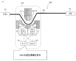
図10は、本実施形態の光ファイバ表示システム301を説明する図である。光ファイバ表示システム301は、心線対照端末101を複数備える光ファイバ表示システムであって、
心線対照端末101は、
光ファイバ50の任意の位置に曲げを形成し、前記曲げから光ファイバ50を伝搬する光信号を漏洩させる曲げ形成部11と、
漏洩した前記光信号に含まれる、光ファイバ50の両端に接続されている通信機器(51、52)の識別番号を取得する解析部12と、
取得した前記通信機器の識別番号を、光ファイバと通信機器との関係を記憶するデータベース201に問い合わせ、取得した前記通信機器の識別番号に対応する光ファイバ50の識別番号をデータベース201から受信する通信部13と、
取得した前記通信機器の識別番号と受信した光ファイバ50の識別番号を表示する表示部14と、
を有する。
なお、光ファイバ表示システム301は、図14以降の説明のように心線対照端末101を2つ備えるが、図10から図13では、説明のため心線対照端末101を1つのみ表示している。
心線対照端末101は、
光ファイバ50の任意の位置に曲げを形成し、前記曲げから光ファイバ50を伝搬する光信号を漏洩させる曲げ形成部11と、
漏洩した前記光信号に含まれる、光ファイバ50の両端に接続されている通信機器(51、52)の識別番号を取得する解析部12と、
取得した前記通信機器の識別番号を、光ファイバと通信機器との関係を記憶するデータベース201に問い合わせ、取得した前記通信機器の識別番号に対応する光ファイバ50の識別番号をデータベース201から受信する通信部13と、
取得した前記通信機器の識別番号と受信した光ファイバ50の識別番号を表示する表示部14と、
を有する。
なお、光ファイバ表示システム301は、図14以降の説明のように心線対照端末101を2つ備えるが、図10から図13では、説明のため心線対照端末101を1つのみ表示している。
OLT51とONU52から出力される通信光の中には、それぞれに割り振られた特有の識別番号となるMACアドレス(Media Access Control address:以後、MACアドレスと省略)が含まれている。そのMACアドレスを光ファイバの切断及び接続を実施している工事現場で取得することで、効率的な工事ができる。本実施形態では、MACアドレスの取得方法について述べる。
通信光を屋外で簡易に取り出す方法として、光ファイバを曲げる方法がある。光ファイバのコアに閉じ込められている通信光は、光ファイバを曲げるとコアの外部に漏れ出す。光ファイバは細くしなやかなため、光ファイバを曲げる行為は工事現場では最適である。
光ファイバ50の両端にOLT51とONU52が接続されており、OLT51とONU52が通信をしている。心線対照端末101を光ファイバ50の所望の位置に配置する。光ファイバ50を凹型と凸型の曲げ形成部11で挟み込むことで光ファイバ50を曲げる。曲げられた光ファイバ50は、OLT51とONU52のそれぞれの通信光が曲げ部から別々に漏洩する。
解析部12は、漏洩光を取得して解析する。解析部12には、フォトダイオードの一種であるアバランシェフォトダイオード(avalanche photodiode:APDと省略)を用いる。通信光は高速のため、低速のフォトダイオードであると信号の解析ができないためである。解析部12は、APDで光信号から電気信号に変換し、その電気信号の中からMACアドレスの情報のみを取り出し、表示部14でMACアドレスを表示する。
(実施形態2)
図11から図13は、本実施形態を説明する図である。実施形態1で説明したように、光ファイバ50を曲げて、OLT51とONU52のMACアドレスを取得したとする。しかし、表示部14に表示されるMACアドレスは数値の羅列なので、作業者はそれを見ただけでは切り替え工事対象の光ファイバであるかどうか判断できない。
図11から図13は、本実施形態を説明する図である。実施形態1で説明したように、光ファイバ50を曲げて、OLT51とONU52のMACアドレスを取得したとする。しかし、表示部14に表示されるMACアドレスは数値の羅列なので、作業者はそれを見ただけでは切り替え工事対象の光ファイバであるかどうか判断できない。
そこで、本実施形態では、光アクセス網を管理しているデータベース201と通信する通信部13を利用する。通信部13は、例えば、作業者が携帯可能なタブレット端末である。心線対照端末101、通信部13及びデータベース201との間は、例えば、無線で通信することができる。
心線対照端末101は、OLT51とONU52のMACアドレスを取得する。例えば、OLT51のMACアドレスを123456、ONU52のMACアドレスをabcdefとする。タブレット(通信部13)は、この情報をデータベース201に照会する。データベース201は、光ファイバそれぞれにつながっているOLTとONUのMACアドレス、接続ポイント数、光ファイバの長さ等を管理している。データベース201に当該MACアドレスの情報を照会すると、データベース201から当該MACアドレスに対応する光ファイバの番号がタブレットに送信される。タブレットは、その光ファイバの番号を画面上に表示する。例えば、表示された光ファイバの番号を1とする。
作業員は、図13のように現在選択している光ファイバの番号を認知できる。作業員は、その番号と工事指示書などで指示されている光ファイバの番号と一致していることを確認後、工事を開始する。従って、通信ビルの作業員を配置せずとも現場の作業員のみで工事対象の光ファイバの確認ができる。
(実施形態3)
図14は、本実施形態を説明する図である。光ファイバ50の切替工事は、通信ビル以外で2ヶ所であることを図2から図4で示した。作業員2と作業員3が2ヶ所に別れ、それぞれが光ファイバ50の切断と接続を行う。両者が正しい光ファイバ50に対して、作業を行わないといけない。つまり、作業員2が切断した光ファイバとは違う光ファイバを作業員3が切断することは許されない。よって、両者の情報を共有できる仕組みが必要である。そこで、新たに機能として下記の2点をタブレットに持たせる。
(1)GPS機能
(2)タブレット間同士を認識し、同じ情報を複数のタブレットの表示させる機能
図14は、本実施形態を説明する図である。光ファイバ50の切替工事は、通信ビル以外で2ヶ所であることを図2から図4で示した。作業員2と作業員3が2ヶ所に別れ、それぞれが光ファイバ50の切断と接続を行う。両者が正しい光ファイバ50に対して、作業を行わないといけない。つまり、作業員2が切断した光ファイバとは違う光ファイバを作業員3が切断することは許されない。よって、両者の情報を共有できる仕組みが必要である。そこで、新たに機能として下記の2点をタブレットに持たせる。
(1)GPS機能
(2)タブレット間同士を認識し、同じ情報を複数のタブレットの表示させる機能
つまり、前記心線対照端末は、自身の位置を把握する位置情報取得部をさらに有しており、
前記心線対照端末の前記通信部は、前記通信機器の識別番号、前記前記光ファイバの識別番号、及び把握した前記自身の位置を互いに通知し合い、
前記心線対照端末の前記表示部は、他の前記心線対照端末から通知された前記通信機器の識別番号、前記前記光ファイバの識別番号、及び他の前記心線対照端末の位置も表示することを特徴とする。
前記心線対照端末の前記通信部は、前記通信機器の識別番号、前記前記光ファイバの識別番号、及び把握した前記自身の位置を互いに通知し合い、
前記心線対照端末の前記表示部は、他の前記心線対照端末から通知された前記通信機器の識別番号、前記前記光ファイバの識別番号、及び他の前記心線対照端末の位置も表示することを特徴とする。
図14では、2名の作業員(作業員2と作業員3)、両者とも心線対照端末101を用い、OLT51とONU52のMACアドレス情報を取得し、さらにタブレット(通信部13)でデータベース201にアクセスしている。タブレットがGPS機能を持つことで、作業員は自身の位置が分かる。さらに、タブレット間で通信することで図15に示すような情報を作業員2と作業員3とで共有できる。
光ファイバの切り替えポイントは、光ファイバごとに異なるケースがある。この場合、1つの光ファイバの工事が終わったら、他の光ファイバの工事をするために作業員が移動しなければならない。タブレットにGPS機能を持たせることで、作業員同士が可視化でき、作業員が移動していく様子をリアルタイムに画面に表示することができる。
(実施形態4)
図15についてさらに説明する。作業員2名は、光ファイバ50を曲げてONU52とOLT51のMACアドレスを取得し、データベースより光ファイバの番号を取得する。各タブレットは、その作業員2名分の情報を画面上に表示する。さらに、タブレットはGPS機能を利用して互いの位置を把握し、作業員2と作業員3との距離を画面上に表示する。
図15についてさらに説明する。作業員2名は、光ファイバ50を曲げてONU52とOLT51のMACアドレスを取得し、データベースより光ファイバの番号を取得する。各タブレットは、その作業員2名分の情報を画面上に表示する。さらに、タブレットはGPS機能を利用して互いの位置を把握し、作業員2と作業員3との距離を画面上に表示する。
(実施形態5)
図16から図22は、本実施形態の光ファイバ切替方法を説明する図である。本光ファイバ切替方法は、OLTとONUとの間を光ファイバで接続する光アクセス網において、前記光ファイバの一部区間を現用光ファイバから新たな新設光ファイバへ切り替える光ファイバ切替方法であって、
切り替え対象の前記現用光ファイバを特定する特定工程と、
前記現用光ファイバを切断する切断工程と、
前記データベースの情報を更新する情報更新工程と、
前記新設光ファイバを接続する接続工程と、
前記新設光ファイバを接続した後に行う確認工程と、
を行うことを特徴とする。
図16から図22は、本実施形態の光ファイバ切替方法を説明する図である。本光ファイバ切替方法は、OLTとONUとの間を光ファイバで接続する光アクセス網において、前記光ファイバの一部区間を現用光ファイバから新たな新設光ファイバへ切り替える光ファイバ切替方法であって、
切り替え対象の前記現用光ファイバを特定する特定工程と、
前記現用光ファイバを切断する切断工程と、
前記データベースの情報を更新する情報更新工程と、
前記新設光ファイバを接続する接続工程と、
前記新設光ファイバを接続した後に行う確認工程と、
を行うことを特徴とする。
前記特定工程は、前記一部区間の両端において、心線対照端末を用いて前記OLTと前記ONUの通信機器の識別番号を取得し、取得した前記通信機器の識別番号を、光ファイバ、OLT及びONUの関係を記憶するデータベースに問い合わせ、取得した前記通信機器の識別番号に対応する前記光ファイバの識別番号が切り替え対象の前記現用光ファイバであることを前記心線対照端末で確認する。
前記切断工程は、前記一部区間の両端の内、先に前記ONU側の端を切断し、前記OLT側の前記心線対照端末に前記ONUの前記通信機器の識別番号が未表示となった後に前記OLT側の端を切断する。
前記情報更新工程は、前記データベースの前記光ファイバの識別番号を前記現用光ファイバの識別番号から前記新設光ファイバの識別番号へ書き換える。
前記接続工程は、前記一部区間の両端の内、先に前記OLT側の端に接続し、前記OLT側の前記心線対照端末に前記OLTの前記通信機器の識別番号が表示された後に前記ONU側の端に接続する。
前記確認工程は、前記一部区間の両端において、前記心線対照端末を用いて前記OLTと前記ONUの通信機器の識別番号を取得し、取得した前記通信機器の識別番号を前記データベースに問い合わせ、取得した前記通信機器の識別番号及び取得した前記通信機器の識別番号に対応する前記光ファイバの識別番号を前記心線対照端末で確認する。
実施形態3及び4で示した機能を有するタブレットを作業員2名が持つことで、光ファイバの切り替えを工事現場の作業員だけで可能であることを以下に説明する。
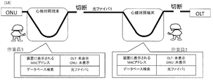
図16は、前記特定工程を説明する図である。本工程では、作業員2名が保有しているタブレットにOLTとONUのMACアドレスが表示され、そのMACアドレスが登録されている光ファイバの番号をデータベースに照会する。そして、照会結果の光ファイバの番号がタブレットに示される。図16では、工事対象の光ファイバの番号である“1”が表示されたので、光ファイバを特定できた結果である。
図17は、前記切断工程のうち、ONU側(作業者3側)の光ファイバを切断する工程を説明する図である。OLTとONUは互いを認識しながら通信をしている。ここで、光ファイバを切断すると、OLTは一方的に光信号を出力し続けるが、ONUはOLTの信号が到着しない場合、通信を止める。よって、作業員3が光ファイバを切断するとONUから出力される光信号は止まるが、OLTから出力される光信号は維持される。
作業員3から見るとOLT側で光ファイバが切断されているため、OLTからの光信号が到達しなくなり、作業員3の表示欄においてOLTのMACアドレスは未表示となる。また、OLTからの光信号がONUにも到達しないため、ONUが光信号を出力せず、作業員3の表示欄においてONUのMACアドレスも未表示となる。
一方、作業員2からみるとONU側で光ファイバが切断されているため、OLTの信号のみが到達する。このため、作業員2の表示欄においてOLTのMACアドレスのみ表示される。作業員2の表示欄においてONUのMACアドレスは未表示である。
よって、タブレットの表示欄の表示状況から、作業員3が光ファイバを切断したことが把握できる。そして、その表示状況は、両作業員のタブレットに表示されるため、両作業員ともその情報を共有できる。
図18は、前記切断工程のうち、OLT側(作業者2側)の光ファイバを切断する工程を説明する図である。OLT側の光ファイバを切断する箇所は、心線対照端末とOLTとの間である。この箇所を切断すると、OLTからの光信号も作業員2の心線対照端末に到着しないため、作業員2の表示欄においてOLTのMACアドレスが未表示となる。つまり、すべての表示欄においてMACアドレスが未表示となる。
よって、タブレットの表示欄の表示状況から、作業員2が光ファイバを切断したことが把握できる。そして、その表示状況は、両作業員のタブレットに表示されるため、両作業員ともその情報を共有できる。
図19は、切断した光ファイバを撤去し、新設の光ファイバを準備していることを説明する図である。この状態ではタブレットの表示に変化は無い。
図20は、前記接続工程のうち、OLT側(作業者2側)に新設の光ファイバを接続する工程を説明する図である。OLT側に新設の光ファイバ3を接続すると、OLTからの光信号が作業員2の心線対照端末に到達し、作業員2の表示欄にOLTのMACアドレスが表示される。よって、タブレットの表示欄の表示状況から、作業員2が新設の光ファイバを接続したことが把握できる。そして、その表示状況は、両作業員のタブレットに表示されるため、両作業員ともその情報を共有できる。
なお、接続工程の前あるいは接続工程中に情報更新工程を行っておくことが好ましい。情報更新工程では、作業員2又は3が、タブレットに現用光ファイバ1から新設光ファイバ3へ変更することを書き込む。そうすると、タブレットはデータベースにアクセスし、データベースの情報を更新する。この結果、接続工程にてタブレットに表示欄に表示される光ファイバの番号が“1(現用)”から“3(新設)”に変更される。
図22は、前記接続工程のうち、ONU側(作業者3側)に新設の光ファイバを接続する工程を説明する図である。作業員3が新設の光ファイバ3をONU側に接続するとOLTとONUとの通信が回復する。OLTからの光信号が作業員3の心線対照端末にも到達し、作業員3の表示欄にもOLTのMACアドレスが表示される。さらに、ONUも光信号を出力し始めるので、両作業員の心線対照端末にONUからの光信号が到達し、両作業員の表示欄にONUのMACアドレスが表示される。
よって、タブレットの表示欄の表示状況から、作業員3が新設の光ファイバを接続したことが把握できる。そして、その表示状況は、両作業員のタブレットに表示されるため、両作業員ともその情報を共有できる。そして、この状態は、切替工事が終わったことを示す。
従来は、通信ビルから作業員がOTDR試験装置を用いて工事現場の作業員に対して指示を出していた。しかし、光ファイバ表示システム301用いることで、工事現場で確認作業ができ、光ファイバの切替工事を実施できる。作業員を減らしつつ、作業を工事現場に集約できるため、従来の工法と比べると明らかに効率が良い。
(実施形態6)
図23は、本実施形態の光ファイバ表示システム301を説明する図である。心線対照端末101の解析部12は、漏洩した前記光信号に含まれる、前記通信機器(ONU52)が送信した認証情報を取得し、表示部14は、取得した前記通信機器の識別番号と受信した光ファイバ50の識別番号とともに取得した前記認証情報も表示する。
図23は、本実施形態の光ファイバ表示システム301を説明する図である。心線対照端末101の解析部12は、漏洩した前記光信号に含まれる、前記通信機器(ONU52)が送信した認証情報を取得し、表示部14は、取得した前記通信機器の識別番号と受信した光ファイバ50の識別番号とともに取得した前記認証情報も表示する。
光ファイバの切替工事では、光ファイバの切断や接続を繰り返すが、最終的には、切り替えた後の新設光ファイバでOLT51とONU52間で通信を開始しなければならない。通常、OLT51とONU52との通信がされるときには、ONU52の上り光信号に認証情報が含まれる。このため、この認証情報を取得しなければ、通信が開始したことにならず、切り替え工事が終わったことにならない。
本実施形態では、前記確認工程で、ONUからの認証情報も取得し、心線対照端末101で確認することを特徴とする。図23に示すように、心線対照端末101は、光ファイバ50を曲げてMACアドレスを取得するだけではなく、さらに、ONU52の光信号に含まれる認証情報も工事現場で取得できる。つまり、光ファイバ表示システム301は、切り替え工事を行っている現場で通信が再開した証明を得ることができる。
(実施形態7)
図24は、本実施形態の光ファイバ表示システム301を説明する図である。心線対照端末101の通信部13は、データベース201が記憶する光ファイバと通信機器との関係を修正する修正信号をデータベース201に送信することを特徴とする。本実施形態では、前記切断工程で前記現用光ファイバを切断した位置情報、及び前記確認工程で取得した前記通信機器の識別番号と前記認証情報を前記データベースに登録する登録工程をさらに行う。
図24は、本実施形態の光ファイバ表示システム301を説明する図である。心線対照端末101の通信部13は、データベース201が記憶する光ファイバと通信機器との関係を修正する修正信号をデータベース201に送信することを特徴とする。本実施形態では、前記切断工程で前記現用光ファイバを切断した位置情報、及び前記確認工程で取得した前記通信機器の識別番号と前記認証情報を前記データベースに登録する登録工程をさらに行う。
例えば、図24に示すように、漏洩光を分析することでONU52のMACアドレスと認証情報を同時に取得することができる。その情報とともに、確認した日時、GPS機能による工事の場所、光ファイバが設置される電柱番号もタブレットに表示できる。つまり、いつ、どこで、どのONU52(MACアドレスから)から通信が回復したことを、一括で表示でき、それが工事現場でリアルタイムに確認できる。
当該タブレットは、その情報をデータベース201に登録する。データベース201に当該情報を登録することで、該当する光ファイバの切り替え工事が完了することになる。
従来であれば、現場で取得したデータを事務所に持ち帰り、そのデータを手入力をしてデータベースに登録していた。また、工事が終えてから時間がたっているため、工事をした作業員も工事内容を明確に覚えていないこともある。本システムを用いることで、工事現場となるその場で登録ができる。
11:曲げ形成部
12:解析部
13:通信部
14:表示部
50:光ファイバ
51:OLT
52:ONU
101:心線対照端末
201:データベース
301:光ファイバ表示システム
12:解析部
13:通信部
14:表示部
50:光ファイバ
51:OLT
52:ONU
101:心線対照端末
201:データベース
301:光ファイバ表示システム
Claims (8)
- 心線対照端末を複数備える光ファイバ表示システムであって、
前記心線対照端末は、
光ファイバの任意の位置に曲げを形成し、前記曲げから前記光ファイバを伝搬する光信号を漏洩させる曲げ形成部と、
漏洩した前記光信号に含まれる、前記光ファイバの両端に接続されている通信機器の識別番号を取得する解析部と、
取得した前記通信機器の識別番号を、光ファイバと通信機器との関係を記憶するデータベースに問い合わせ、取得した前記通信機器の識別番号に対応する前記光ファイバの識別番号を前記データベースから受信する通信部と、
取得した前記通信機器の識別番号と受信した前記光ファイバの識別番号を表示する表示部と、
を有することを特徴とする光ファイバ表示システム。 - 前記心線対照端末は、自身の位置を把握する位置情報取得部をさらに有しており、
前記心線対照端末の前記通信部は、前記通信機器の識別番号、前記前記光ファイバの識別番号、及び把握した前記自身の位置を互いに通知し合い、
前記心線対照端末の前記表示部は、他の前記心線対照端末から通知された前記通信機器の識別番号、前記前記光ファイバの識別番号、及び他の前記心線対照端末の位置も表示することを特徴とする請求項1に記載の光ファイバ表示システム。 - 前記解析部は、
漏洩していた前記光信号が消滅した場合に前記表示部に前記通信機器の識別番号を未表示とさせ、
消滅していた前記光信号が再度漏洩した場合に前記通信部に再度問い合わせを行わせて、新たに取得した前記通信機器の識別番号に対応する前記光ファイバの識別番号を前記データベースから受信させ、前記表示部に新たに取得した前記通信機器の識別番号と受信した前記光ファイバの識別番号を表示させる
ことを特徴とする請求項1又は2に記載の光ファイバ表示システム。 - 前記解析部は、漏洩した前記光信号に含まれる、前記通信機器が送信した認証情報を取得し、
前記表示部は、取得した前記通信機器の識別番号と受信した前記光ファイバの識別番号とともに取得した前記認証情報も表示する
ことを特徴とする請求項1から3のいずれかに記載の光ファイバ表示システム。 - 前記通信部は、前記データベースが記憶する光ファイバと通信機器との関係を修正する修正信号を前記データベースに送信することを特徴とする請求項1から4のいずれかに記載の光ファイバ表示システム。
- 光加入者線終端装置(Optical Line Terminal:OLT)と光加入者線ネットワーク装置(Optical Network Unit:ONU)との間を光ファイバで接続する光アクセス網において、前記光ファイバの一部区間を現用光ファイバから新たな新設光ファイバへ切り替える光ファイバ切替方法であって、
切り替え対象の前記現用光ファイバを特定する特定工程であって、前記一部区間の両端において、心線対照端末を用いて前記OLTと前記ONUの通信機器の識別番号を取得し、取得した前記通信機器の識別番号を、光ファイバ、OLT及びONUの関係を記憶するデータベースに問い合わせ、取得した前記通信機器の識別番号に対応する前記光ファイバの識別番号が切り替え対象の前記現用光ファイバであることを前記心線対照端末で確認する特定工程と、
前記現用光ファイバを切断する切断工程であって、前記一部区間の両端の内、先に前記ONU側の端を切断し、前記OLT側の前記心線対照端末に前記ONUの前記通信機器の識別番号が未表示となった後に前記OLT側の端を切断する切断工程と、
前記データベースの情報を更新する情報更新工程であって、前記データベースの前記光ファイバの識別番号を前記現用光ファイバの識別番号から前記新設光ファイバの識別番号へ書き換える情報更新工程と、
前記新設光ファイバを接続する接続工程であって、前記一部区間の両端の内、先に前記OLT側の端に接続し、前記OLT側の前記心線対照端末に前記OLTの前記通信機器の識別番号が表示された後に前記ONU側の端に接続する接続工程と、
前記新設光ファイバを接続した後に行う確認工程であって、前記一部区間の両端において、前記心線対照端末を用いて前記OLTと前記ONUの通信機器の識別番号を取得し、取得した前記通信機器の識別番号を前記データベースに問い合わせ、取得した前記通信機器の識別番号及び取得した前記通信機器の識別番号に対応する前記光ファイバの識別番号を前記心線対照端末で確認する確認工程と、
を行うことを特徴とする光ファイバ切替方法。 - 前記確認工程で、前記ONUからの認証情報も取得し、前記心線対照端末で確認することを特徴とする請求項6に記載の光ファイバ切替方法。
- 光ファイバの切り替え作業が完了したことを前記データベースに登録する登録工程であって、前記切断工程で前記現用光ファイバを切断した位置情報、及び前記確認工程で取得した前記通信機器の識別番号と前記認証情報を前記データベースに登録する登録工程をさらに行うことを特徴とする請求項7に記載の光ファイバ切替方法。
Priority Applications (1)
| Application Number | Priority Date | Filing Date | Title |
|---|---|---|---|
| US17/600,537 US11711144B2 (en) | 2019-04-03 | 2020-03-19 | Optical fiber display system and optical fiber switching method |
Applications Claiming Priority (2)
| Application Number | Priority Date | Filing Date | Title |
|---|---|---|---|
| JP2019071646A JP7268455B2 (ja) | 2019-04-03 | 2019-04-03 | 光ファイバ表示システム及び光ファイバ切替方法 |
| JP2019-071646 | 2019-04-03 |
Publications (1)
| Publication Number | Publication Date |
|---|---|
| WO2020203333A1 true WO2020203333A1 (ja) | 2020-10-08 |
Family
ID=72668414
Family Applications (1)
| Application Number | Title | Priority Date | Filing Date |
|---|---|---|---|
| PCT/JP2020/012212 Ceased WO2020203333A1 (ja) | 2019-04-03 | 2020-03-19 | 光ファイバ表示システム及び光ファイバ切替方法 |
Country Status (3)
| Country | Link |
|---|---|
| US (1) | US11711144B2 (ja) |
| JP (1) | JP7268455B2 (ja) |
| WO (1) | WO2020203333A1 (ja) |
Cited By (1)
| Publication number | Priority date | Publication date | Assignee | Title |
|---|---|---|---|---|
| WO2022079843A1 (ja) * | 2020-10-14 | 2022-04-21 | 日本電信電話株式会社 | モニタ装置及び光ファイバ特定方法 |
Families Citing this family (6)
| Publication number | Priority date | Publication date | Assignee | Title |
|---|---|---|---|---|
| US11683091B2 (en) * | 2019-06-18 | 2023-06-20 | Nippon Telegraph And Telephone Corporation | Communication apparatus identification device, optical fiber connection system, communication apparatus identification method, and optical fiber connection method |
| US12107624B2 (en) * | 2020-06-26 | 2024-10-01 | Nippon Telegraph And Telephone Corporation | Termination determination device and termination determination method |
| US20240280436A1 (en) * | 2021-06-10 | 2024-08-22 | Nippon Telegraph And Telephone Corporation | Visualization device, visualization method, visualization program |
| US20240322904A1 (en) * | 2021-06-30 | 2024-09-26 | Telefonaktiebolaget Lm Ericsson (Publ) | A method for determining information associated with an optical component system |
| WO2023190119A1 (ja) | 2022-03-31 | 2023-10-05 | 第一稀元素化学工業株式会社 | ジルコニア粉末、ジルコニア焼結体、及び、ジルコニア焼結体の製造方法 |
| US12244982B2 (en) | 2022-08-05 | 2025-03-04 | Viavi Solutions Inc. | Mapping ports in a passive optical network |
Citations (3)
| Publication number | Priority date | Publication date | Assignee | Title |
|---|---|---|---|---|
| JP2012060290A (ja) * | 2010-09-07 | 2012-03-22 | Nippon Telegr & Teleph Corp <Ntt> | 光通信システム及び接続状態判定方法 |
| JP2015132775A (ja) * | 2014-01-15 | 2015-07-23 | 日本電信電話株式会社 | 通信モニタ用受光装置とその漏洩光取得方法 |
| JP2017049214A (ja) * | 2015-09-04 | 2017-03-09 | 日本電信電話株式会社 | 光ファイバ側方入出力装置及び光線路切替システム |
Family Cites Families (4)
| Publication number | Priority date | Publication date | Assignee | Title |
|---|---|---|---|---|
| US20050041902A1 (en) * | 2003-08-20 | 2005-02-24 | Frigo Nicholas J. | Method, apparatus and system for minimally intrusive fiber identification |
| JP5399050B2 (ja) * | 2008-11-17 | 2014-01-29 | 株式会社フジクラ | 光ファイバ曲げ受光器 |
| US8976344B2 (en) * | 2013-04-16 | 2015-03-10 | Ofs Fitel, Llc | Live optical fiber identifier tool |
| US10790908B1 (en) * | 2019-04-05 | 2020-09-29 | Verizon Patent And Licensing Inc. | Optical communication link identifier |
-
2019
- 2019-04-03 JP JP2019071646A patent/JP7268455B2/ja active Active
-
2020
- 2020-03-19 US US17/600,537 patent/US11711144B2/en active Active
- 2020-03-19 WO PCT/JP2020/012212 patent/WO2020203333A1/ja not_active Ceased
Patent Citations (3)
| Publication number | Priority date | Publication date | Assignee | Title |
|---|---|---|---|---|
| JP2012060290A (ja) * | 2010-09-07 | 2012-03-22 | Nippon Telegr & Teleph Corp <Ntt> | 光通信システム及び接続状態判定方法 |
| JP2015132775A (ja) * | 2014-01-15 | 2015-07-23 | 日本電信電話株式会社 | 通信モニタ用受光装置とその漏洩光取得方法 |
| JP2017049214A (ja) * | 2015-09-04 | 2017-03-09 | 日本電信電話株式会社 | 光ファイバ側方入出力装置及び光線路切替システム |
Non-Patent Citations (1)
| Title |
|---|
| HIROTA H. ET AL.: "Optical Cable Changeover Tool With Light Injection and Detection Technology", JOURNAL OF LIGHTWAVE TECHNOLOGY, vol. 34, no. 14, 15 July 2016 (2016-07-15), pages 3379 - 3388, XP011615718, DOI: 10.1109/JLT.2016.2568221 * |
Cited By (3)
| Publication number | Priority date | Publication date | Assignee | Title |
|---|---|---|---|---|
| WO2022079843A1 (ja) * | 2020-10-14 | 2022-04-21 | 日本電信電話株式会社 | モニタ装置及び光ファイバ特定方法 |
| JPWO2022079843A1 (ja) * | 2020-10-14 | 2022-04-21 | ||
| JP7424506B2 (ja) | 2020-10-14 | 2024-01-30 | 日本電信電話株式会社 | モニタ装置及び光ファイバ特定方法 |
Also Published As
| Publication number | Publication date |
|---|---|
| JP7268455B2 (ja) | 2023-05-08 |
| US11711144B2 (en) | 2023-07-25 |
| US20220166502A1 (en) | 2022-05-26 |
| JP2020170949A (ja) | 2020-10-15 |
Similar Documents
| Publication | Publication Date | Title |
|---|---|---|
| JP7268455B2 (ja) | 光ファイバ表示システム及び光ファイバ切替方法 | |
| CN104467959A (zh) | 使用光损耗测试仪器的免提光纤测试 | |
| DE60025377D1 (de) | Verfahren und system für den schutz einer nutzeridentität | |
| WO2015196638A1 (zh) | 光纤检测方法、检测设备、检测平台及网元管理系统 | |
| JP5887536B2 (ja) | 機器管理システムおよび機器管理方法 | |
| JP5467080B2 (ja) | 光線路心線判定装置およびその判定方法 | |
| JP5315269B2 (ja) | 光設備判定システム及び判定方法 | |
| JP6106144B2 (ja) | 光ファイバ試験装置及び光ファイバ試験システム | |
| CN108123751B (zh) | 光缆故障快速定位的方法、设备及系统 | |
| CN105791029A (zh) | 用于工程质量检测的信息处理方法、系统和检测员终端 | |
| CN118740254A (zh) | 一种路由普查方法、系统和存储介质 | |
| JP7424506B2 (ja) | モニタ装置及び光ファイバ特定方法 | |
| JP2017050970A (ja) | 中継装置及びエネルギマネジメントシステム | |
| CN111416957B (zh) | 一种巡视检修系统及方法 | |
| JP2013120117A (ja) | 光線路心線判定装置およびその判定方法 | |
| KR100893625B1 (ko) | 원격 제어 지원 가능한 홍수 예/경보 시스템 | |
| JP2013026765A (ja) | 展示物説明システム | |
| JP5649222B2 (ja) | Pon接続工事方法及び光パルス試験装置 | |
| CN113490082A (zh) | 一种光缆看护接口模块 | |
| CN106358284B (zh) | 一种位置信息确定方法及装置 | |
| CN104467954A (zh) | 检测光纤路由信息的装置、系统及方法 | |
| JP5988229B2 (ja) | 機器管理システムおよび機器管理方法 | |
| JP5958901B2 (ja) | 通信情報提供システム、情報提供装置、端末、及び、無線アクセスポイントの選択方法 | |
| JP6472636B2 (ja) | 光パルス測定システム | |
| JP2006330881A (ja) | 端末機器の設定方法 |
Legal Events
| Date | Code | Title | Description |
|---|---|---|---|
| 121 | Ep: the epo has been informed by wipo that ep was designated in this application |
Ref document number: 20782804 Country of ref document: EP Kind code of ref document: A1 |
|
| NENP | Non-entry into the national phase |
Ref country code: DE |
|
| 122 | Ep: pct application non-entry in european phase |
Ref document number: 20782804 Country of ref document: EP Kind code of ref document: A1 |