WO2020203324A1 - ブレーキ制御装置 - Google Patents
ブレーキ制御装置 Download PDFInfo
- Publication number
- WO2020203324A1 WO2020203324A1 PCT/JP2020/012136 JP2020012136W WO2020203324A1 WO 2020203324 A1 WO2020203324 A1 WO 2020203324A1 JP 2020012136 W JP2020012136 W JP 2020012136W WO 2020203324 A1 WO2020203324 A1 WO 2020203324A1
- Authority
- WO
- WIPO (PCT)
- Prior art keywords
- brake
- braking force
- control device
- determination threshold
- vehicle
- Prior art date
- Legal status (The legal status is an assumption and is not a legal conclusion. Google has not performed a legal analysis and makes no representation as to the accuracy of the status listed.)
- Ceased
Links
Images
Classifications
-
- B—PERFORMING OPERATIONS; TRANSPORTING
- B60—VEHICLES IN GENERAL
- B60T—VEHICLE BRAKE CONTROL SYSTEMS OR PARTS THEREOF; BRAKE CONTROL SYSTEMS OR PARTS THEREOF, IN GENERAL; ARRANGEMENT OF BRAKING ELEMENTS ON VEHICLES IN GENERAL; PORTABLE DEVICES FOR PREVENTING UNWANTED MOVEMENT OF VEHICLES; VEHICLE MODIFICATIONS TO FACILITATE COOLING OF BRAKES
- B60T8/00—Arrangements for adjusting wheel-braking force to meet varying vehicular or ground-surface conditions, e.g. limiting or varying distribution of braking force
- B60T8/17—Using electrical or electronic regulation means to control braking
- B60T8/176—Brake regulation specially adapted to prevent excessive wheel slip during vehicle deceleration, e.g. ABS
- B60T8/1761—Brake regulation specially adapted to prevent excessive wheel slip during vehicle deceleration, e.g. ABS responsive to wheel or brake dynamics, e.g. wheel slip, wheel acceleration or rate of change of brake fluid pressure
- B60T8/17616—Microprocessor-based systems
-
- B—PERFORMING OPERATIONS; TRANSPORTING
- B60—VEHICLES IN GENERAL
- B60T—VEHICLE BRAKE CONTROL SYSTEMS OR PARTS THEREOF; BRAKE CONTROL SYSTEMS OR PARTS THEREOF, IN GENERAL; ARRANGEMENT OF BRAKING ELEMENTS ON VEHICLES IN GENERAL; PORTABLE DEVICES FOR PREVENTING UNWANTED MOVEMENT OF VEHICLES; VEHICLE MODIFICATIONS TO FACILITATE COOLING OF BRAKES
- B60T13/00—Transmitting braking action from initiating means to ultimate brake actuator with power assistance or drive; Brake systems incorporating such transmitting means, e.g. air-pressure brake systems
- B60T13/10—Transmitting braking action from initiating means to ultimate brake actuator with power assistance or drive; Brake systems incorporating such transmitting means, e.g. air-pressure brake systems with fluid assistance, drive, or release
- B60T13/12—Transmitting braking action from initiating means to ultimate brake actuator with power assistance or drive; Brake systems incorporating such transmitting means, e.g. air-pressure brake systems with fluid assistance, drive, or release the fluid being liquid
- B60T13/14—Transmitting braking action from initiating means to ultimate brake actuator with power assistance or drive; Brake systems incorporating such transmitting means, e.g. air-pressure brake systems with fluid assistance, drive, or release the fluid being liquid using accumulators or reservoirs fed by pumps
- B60T13/142—Systems with master cylinder
- B60T13/145—Master cylinder integrated or hydraulically coupled with booster
- B60T13/146—Part of the system directly actuated by booster pressure
-
- B—PERFORMING OPERATIONS; TRANSPORTING
- B60—VEHICLES IN GENERAL
- B60T—VEHICLE BRAKE CONTROL SYSTEMS OR PARTS THEREOF; BRAKE CONTROL SYSTEMS OR PARTS THEREOF, IN GENERAL; ARRANGEMENT OF BRAKING ELEMENTS ON VEHICLES IN GENERAL; PORTABLE DEVICES FOR PREVENTING UNWANTED MOVEMENT OF VEHICLES; VEHICLE MODIFICATIONS TO FACILITATE COOLING OF BRAKES
- B60T17/00—Component parts, details, or accessories of power brake systems not covered by groups B60T8/00, B60T13/00 or B60T15/00, or presenting other characteristic features
- B60T17/18—Safety devices; Monitoring
-
- B—PERFORMING OPERATIONS; TRANSPORTING
- B60—VEHICLES IN GENERAL
- B60T—VEHICLE BRAKE CONTROL SYSTEMS OR PARTS THEREOF; BRAKE CONTROL SYSTEMS OR PARTS THEREOF, IN GENERAL; ARRANGEMENT OF BRAKING ELEMENTS ON VEHICLES IN GENERAL; PORTABLE DEVICES FOR PREVENTING UNWANTED MOVEMENT OF VEHICLES; VEHICLE MODIFICATIONS TO FACILITATE COOLING OF BRAKES
- B60T7/00—Brake-action initiating means
- B60T7/02—Brake-action initiating means for personal initiation
- B60T7/04—Brake-action initiating means for personal initiation foot actuated
- B60T7/042—Brake-action initiating means for personal initiation foot actuated by electrical means, e.g. using travel or force sensors
-
- B—PERFORMING OPERATIONS; TRANSPORTING
- B60—VEHICLES IN GENERAL
- B60T—VEHICLE BRAKE CONTROL SYSTEMS OR PARTS THEREOF; BRAKE CONTROL SYSTEMS OR PARTS THEREOF, IN GENERAL; ARRANGEMENT OF BRAKING ELEMENTS ON VEHICLES IN GENERAL; PORTABLE DEVICES FOR PREVENTING UNWANTED MOVEMENT OF VEHICLES; VEHICLE MODIFICATIONS TO FACILITATE COOLING OF BRAKES
- B60T7/00—Brake-action initiating means
- B60T7/12—Brake-action initiating means for automatic initiation; for initiation not subject to will of driver or passenger
- B60T7/22—Brake-action initiating means for automatic initiation; for initiation not subject to will of driver or passenger initiated by contact of vehicle, e.g. bumper, with an external object, e.g. another vehicle, or by means of contactless obstacle detectors mounted on the vehicle
-
- B—PERFORMING OPERATIONS; TRANSPORTING
- B60—VEHICLES IN GENERAL
- B60T—VEHICLE BRAKE CONTROL SYSTEMS OR PARTS THEREOF; BRAKE CONTROL SYSTEMS OR PARTS THEREOF, IN GENERAL; ARRANGEMENT OF BRAKING ELEMENTS ON VEHICLES IN GENERAL; PORTABLE DEVICES FOR PREVENTING UNWANTED MOVEMENT OF VEHICLES; VEHICLE MODIFICATIONS TO FACILITATE COOLING OF BRAKES
- B60T8/00—Arrangements for adjusting wheel-braking force to meet varying vehicular or ground-surface conditions, e.g. limiting or varying distribution of braking force
- B60T8/17—Using electrical or electronic regulation means to control braking
- B60T8/176—Brake regulation specially adapted to prevent excessive wheel slip during vehicle deceleration, e.g. ABS
- B60T8/1761—Brake regulation specially adapted to prevent excessive wheel slip during vehicle deceleration, e.g. ABS responsive to wheel or brake dynamics, e.g. wheel slip, wheel acceleration or rate of change of brake fluid pressure
-
- B—PERFORMING OPERATIONS; TRANSPORTING
- B60—VEHICLES IN GENERAL
- B60T—VEHICLE BRAKE CONTROL SYSTEMS OR PARTS THEREOF; BRAKE CONTROL SYSTEMS OR PARTS THEREOF, IN GENERAL; ARRANGEMENT OF BRAKING ELEMENTS ON VEHICLES IN GENERAL; PORTABLE DEVICES FOR PREVENTING UNWANTED MOVEMENT OF VEHICLES; VEHICLE MODIFICATIONS TO FACILITATE COOLING OF BRAKES
- B60T8/00—Arrangements for adjusting wheel-braking force to meet varying vehicular or ground-surface conditions, e.g. limiting or varying distribution of braking force
- B60T8/32—Arrangements for adjusting wheel-braking force to meet varying vehicular or ground-surface conditions, e.g. limiting or varying distribution of braking force responsive to a speed condition, e.g. acceleration or deceleration
- B60T8/88—Arrangements for adjusting wheel-braking force to meet varying vehicular or ground-surface conditions, e.g. limiting or varying distribution of braking force responsive to a speed condition, e.g. acceleration or deceleration with failure responsive means, i.e. means for detecting and indicating faulty operation of the speed responsive control means
- B60T8/92—Arrangements for adjusting wheel-braking force to meet varying vehicular or ground-surface conditions, e.g. limiting or varying distribution of braking force responsive to a speed condition, e.g. acceleration or deceleration with failure responsive means, i.e. means for detecting and indicating faulty operation of the speed responsive control means automatically taking corrective action
- B60T8/96—Arrangements for adjusting wheel-braking force to meet varying vehicular or ground-surface conditions, e.g. limiting or varying distribution of braking force responsive to a speed condition, e.g. acceleration or deceleration with failure responsive means, i.e. means for detecting and indicating faulty operation of the speed responsive control means automatically taking corrective action on speed responsive control means
-
- B—PERFORMING OPERATIONS; TRANSPORTING
- B60—VEHICLES IN GENERAL
- B60T—VEHICLE BRAKE CONTROL SYSTEMS OR PARTS THEREOF; BRAKE CONTROL SYSTEMS OR PARTS THEREOF, IN GENERAL; ARRANGEMENT OF BRAKING ELEMENTS ON VEHICLES IN GENERAL; PORTABLE DEVICES FOR PREVENTING UNWANTED MOVEMENT OF VEHICLES; VEHICLE MODIFICATIONS TO FACILITATE COOLING OF BRAKES
- B60T2270/00—Further aspects of brake control systems not otherwise provided for
- B60T2270/40—Failsafe aspects of brake control systems
- B60T2270/402—Back-up
Definitions
- the present invention relates to a brake control device mounted on a vehicle.
- the front and rear wheels of the vehicle are connected by separate piping.
- the rear wheels simultaneously control the brake fluid pressures of the left and right wheels based on which of the left and right wheels is easier to lock.
- the rear wheels are controlled according to either the left or right wheel, which does not show a locking tendency, to increase the braking force of the rear wheels.
- the brake device in which the front wheel side is an electric hydraulic mechanism and the rear wheel side is an electric mechanism. ..
- the hydraulic mechanical connection between the electric hydraulic mechanism consisting of the pump and valve on the front wheel side and the brake pedal is by closing the valve connecting the hydraulic mechanism and the brake pedal. It is normally separated.
- the electric power on the front wheel side is based on a control amount such as a required braking force calculated based on the stroke of the brake pedal or a pedal force sensor signal, or a required braking force from a vehicle control device provided above the brake control device. It controls the hydraulic mechanism and the electric mechanism on the rear wheel side.
- the valve inside the hydraulic mechanism is opened and the brake caliper on the front wheel side and the brake pedal are directly connected by hydraulic pressure.
- an unassisted braking braking force by the electric mechanism corresponding to the driver's pedal operation is generated on the front wheels, and serves as a backup brake when the electric mechanism part of the electric hydraulic mechanism breaks down.
- the control function of the electric mechanism on the rear wheel side remains, the braking force of the rear wheels is controlled based on the pedal operation amount of the driver.
- Patent Document 1 the control method of the brake device provided with the backup brake that operates when a part of the functions of the brake device fails is not considered.
- the rear wheels are controlled according to one of the left and right wheels, which does not show a locking tendency, to increase the braking force of the rear wheels. As a result, the rear wheels may lock and the running stability of the vehicle may decrease.
- An object of the present invention is to provide a brake control device provided with a backup brake that operates when a part of the functions of the brake device fails, and which can achieve both ensuring deceleration and vehicle running stability. is there.
- the present invention is a brake control device for controlling the braking force of the front wheels and the rear wheels of a vehicle, which is provided on at least one of the front wheels or the rear wheels and is a brake mechanism of one system.
- a backup brake that operates by switching to another system when a failure occurs, and a slip determination threshold setting unit that sets a slip determination threshold are provided, and the slip determination threshold setting unit is provided with the backup brake when the backup brake is activated. It is characterized in that the slip determination threshold value is set based on the braking force information of.
- a brake control device provided with a backup brake that can achieve both ensuring deceleration and vehicle running stability.
- FIG. 1 It is a figure which shows the schematic structure of the brake device of the vehicle which concerns on 1st Embodiment of this invention. It is a figure which shows the schematic structure of the front wheel side braking mechanism of the brake device in FIG. It is a figure which shows the schematic structure of the rear wheel side braking mechanism of the brake device in FIG. 1. It is a block diagram which shows the control executed by the brake control device which concerns on 1st Embodiment of this invention. It is a flowchart which shows the control method of the brake device which concerns on 1st Embodiment of this invention. It is a figure which shows the relationship between the brake pedal operation at the time of braking by the control method shown in FIG. 5, a vehicle speed, a wheel speed, and a slip determination threshold.
- FIG. 1 It is a figure which shows the modification of FIG. It is a flowchart which shows the control executed by the brake control device which concerns on 2nd Embodiment of this invention. It is a block diagram which shows the control executed by the brake control device which concerns on 3rd Embodiment of this invention. It is a flowchart which shows the control executed by the brake control device which concerns on 3rd Embodiment of this invention.
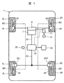
- FIG. 1 is a diagram showing a schematic configuration of a vehicle braking device according to a first embodiment of the present invention
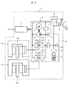
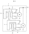
- FIGS. 2 and 3 show a schematic configuration of each braking mechanism on the front wheel side and the rear wheel side in FIG. .
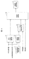
- FIG. 4 is a block diagram showing the control executed by the brake control device 30 according to the first embodiment of the present invention
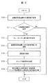
- FIG. 5 is a flowchart showing the control flow.
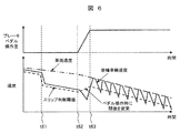
- FIG. 6 shows the relationship between the change in the operation amount of the brake pedal 16 and the vehicle speed, the rear wheel speed, and the slip determination threshold value by the control method shown in FIG.
- the vehicle 1 includes a pair of front wheels 2R and 2L and a pair of rear wheels 3R and 3L, and a front wheel side braking mechanism 4 (see FIG. 2) that applies braking force to the front wheels 2R and 2L. ) And a rear wheel side braking mechanism 5 (see FIG. 3) that applies a braking force to the rear wheels 3R and 3L.
- the front wheel side braking mechanism 4 operates with the brake hydraulic pressure to sandwich the brake disc BD with the hydraulic disc brakes (hydraulic brake mechanism) 4R and 4L, and the front wheel side electric motor that generates the brake hydraulic pressure. It is composed of a hydraulic mechanism 6 and a front wheel side braking control device 7.
- the rear wheel side braking mechanism 5 is operated by the rotation of the electric brake motors 25R and 25L to sandwich the brake disc BD with the electric disc brakes (electric brake mechanism) 5R and 5L, and the electric brake motors 25R and 25L. It is composed of.
- a brake control device 30 that controls the front wheel side braking control device 7 and the electric motors 25R and 25L for braking to adjust the braking force generated by the vehicle 1.
- the front wheel side electric hydraulic mechanism 6 is driven by a pump electric motor 8 which is an electric component element, and is a hydraulic pump 10 which is a hydraulic pressure source for pressurizing the brake fluid in the reservoir tank 9.
- An electromagnetic pressure regulating valve 11 that adjusts the brake fluid pressure of the hydraulic pump 10, an electromagnetic inflow valve 12R, 12L that adjusts the brake fluid that flows into the hydraulic disc brakes 4R, 4L, and an electromagnetic that adjusts the outflowing brake fluid.
- It includes a hydraulic circuit system 15 composed of outflow valves 13R and 13L and electric component elements such as an electromagnetic shutoff valve 14 that shuts off the brake pedal 16 side.
- the front wheel side electric hydraulic pressure mechanism 6 and the hydraulic pressure circuit system 15, which are electric hydraulic pressure systems, are surrounded by the same frame.
- the front wheel side braking mechanism 4 shown in FIG. 2 has a master cylinder 17 that operates by the operation of the brake pedal 16 operated by the driver separately from the front wheel side electric hydraulic pressure mechanism 6.
- the master cylinder 17 is connected to the hydraulic disc brakes 4R and 4L by the hydraulic circuit system 15, the electromagnetic shutoff valve 14 and the electromagnetic inflow valve 12R and 12L are opened, and the electromagnetic outflow valves 13R and 13L are closed. Therefore, the hydraulic disc brakes 4R and 4L can be operated by the brake hydraulic pressure generated by the master cylinder 17 to brake the vehicle 1.
- the master cylinder pressure sensor 20 is in the middle of the hydraulic circuit system 15, the pump pressure sensor 21 is on the discharge side of the hydraulic pump 10, and the caliper pressure sensors 22R, 22L are in the middle of the hydraulic circuit toward the hydraulic disc brakes 4R and 4L. Are attached to each, and the hydraulic pressure of each part of the hydraulic pressure circuit can be detected.
- the hydraulic circuit system 15 is provided with an appropriate reaction force to the driver for the operation of the brake pedal 16 when the electromagnetic shutoff valve 14 is closed, and the brake hydraulic pressure discharged from the master cylinder 17 is applied to the hydraulic circuit system 15.
- a stroke simulator 18 is provided for absorption.
- hydraulic circuit system 15 leading to the stroke simulator 18 is also provided with an electromagnetic stroke simulator valve 19 for adjusting the inflow and outflow of the brake fluid into the stroke simulator 18.
- the electric motor 8 for the pump which is an electric component element
- the electromagnetic pressure regulating valve 11 that functions as an electromagnetic hydraulic pressure control valve
- the electromagnetic inflow valve 12R, 12L the electromagnetic outflow valve 13R, 13L
- the electromagnetic shutoff valve the electromagnetic stroke simulator valve 19 is controlled by the front wheel side braking control device 7.
- a control signal line 23 is connected to the front wheel side braking control device 7.
- the control signal line 23 inputs control command information such as a hydraulic pressure command value of each wheel from the brake control device 30 (see FIG. 1) to the front wheel side braking control device 7, and the electric motor 8 for the pump of the front wheel side braking mechanism 4 It plays a role of outputting drive state information such as a current value and pressure of each part of the hydraulic pressure circuit to the brake control device 30.
- the rear wheel side braking mechanism 5 includes electric disc brakes 5R and 5L.
- the electric disc brakes 5R and 5L have the same configuration.
- the rear wheel side electric mechanism 24 uses the electric brake motors 25R and 25L to use the brake pads 26 as the brake disc BD. Pressing and pressing force are generated to generate braking force.
- the rotational force of the electric brake motors 25R and 25L is converted into a linear motion by the rotation / linear motion conversion mechanism 27, and the brake pad 26 is pressed against the brake disc BD to apply the braking force.
- the rotary / linear motion conversion mechanism 27 adopts, for example, a feed screw mechanism to convert the rotary motion into a linear motion.
- the rear wheel side electric mechanism 24 includes thrust sensors 29R and 29L, and the brake control device 30 controls the rotation of the brake electric motors 25R and 25L based on the pressing force detected by the thrust sensors 29R and 29L. , Adjust the pressing force of the brake pad 26.
- the rear wheel side electric mechanism 24 and the brake control device 30 are connected by a control signal line 23.
- control signal line 23 inputs control command information from the brake control device 30 to the electric brake motors 25R and 25L to drive the pressing force of the rear wheel side braking mechanism 5 and the current value of the electric brake motors 25R and 25L. It plays a role of outputting state information to the brake control device 30.
- the operating amount of the brake pedal 16 (stroke of the brake pedal, pedaling force, etc.) is transmitted to the brake control device 30 as braking force information.
- wheel rotation speed sensors 34 are attached to the front wheels 2R and 2L and the rear wheels 3R and 3L of the vehicle 1, and the wheel speed information is transmitted to the brake control device 30.
- the vehicle motion sensor 35 also detects vehicle behavior information such as acceleration and yaw rate of the vehicle 1 and transmits the vehicle behavior information to the brake control device 30.
- the vehicle 1 is equipped with an upper control device 33.
- the host control device 33 includes external world information from a camera, radar, etc., map information from a navigation system, operating state information of a driving device, a steering device, a braking device, etc. provided in the vehicle 1, motion state information of the vehicle 1, and the like. Based on one or more pieces of information, an appropriate braking operation amount of the vehicle 1 is calculated, and this vehicle braking amount is transmitted to the brake control device 30 as control command information. Further, the host control device 33 obtains the vehicle speed from the GPS function of the radar and the navigation system and transmits the vehicle speed to the brake control device 30.
- the brake control device 30 mounted on the vehicle 1 the operation information obtained from the stroke of the brake pedal 16 by the driver, the master cylinder pressure sensor 20, and the like, and the wheel speeds of the front and rear wheels obtained from the wheel rotation speed sensor 34. Based on the information, the vehicle behavior information of the vehicle 1 obtained from the vehicle motion sensor 35, and the control command information of the upper control device 33, a control command is transmitted to the front wheel side braking control device 7 and the electric brake motors 25R and 25L to transmit the control command to the front wheels. It controls the operation of the side braking mechanism 4 and the rear wheel side braking mechanism 5.
- the front wheel side braking mechanism 4 cuts off the connection between the master cylinder 17 and the hydraulic disc brakes 4R and 4L by closing the electromagnetic shutoff valve 14 during normal control, and the electromagnetic stroke simulator valve 19 Is released to absorb the brake fluid pressure discharged by the operation of the driver's brake pedal 16.
- the brake control device 30 calculates a control amount corresponding to the braking force generated by the front wheels 2R and 2L and the rear wheels 3R and 3L, and transmits the control amount to the front wheel side braking control device 7 and the electric brake motors 25R and 25L.
- the front wheel side braking control device 7 of the front wheel side braking mechanism 4 is based on the control amount command value of the brake control device 30, the electric motor 8 for the pump, the electromagnetic pressure regulating valve 11, the electromagnetic inflow valve 12R, 12L, and the electromagnetic outflow.
- the operation of the valves 13R and 13L is controlled, and the hydraulic disc brakes 4R and 4L generate a braking force.
- the rear wheel side braking mechanism 5 controls the operation of the electric brake motors 25R and 25L based on the control amount command value of the brake control device 30 to adjust the braking force of the electric disc brakes 5R and 5L. There is.
- the backup braking mode is shifted to by taking measures such as shutting off the relay provided in the front wheel side braking control device 7.
- the electromagnetic shutoff valve 14 and the electromagnetic inflow valves 12R and 12L are opened, and the electromagnetic outflow valves 13R and 13L are closed so that the hydraulic disc brake is directly operated by the driver's pedal force to operate the brake pedal 16.
- Operate 4R and 4L That is, the backup brake operates by switching to another system when the brake mechanism of one system fails.
- the electromagnetic shutoff valve 14 and the electromagnetic inflow valves 12R and 12L are in the open state, and the electromagnetic outflow valves 13R and 13L are in the closed state in order to immediately shift to the backup brake mode in the event of a failure.
- the braking mechanism 5 is controlled, and braking force is generated by the electric disc brakes 5R and 5L.
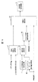
- FIG. 4 is an example of a control block diagram mounted in the brake control device 30 in order to realize control executed when a part of the front wheel side braking mechanism 4 in the first embodiment fails.
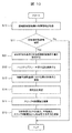
- FIG. 5 is a control flow diagram performed by the brake control device 30 when the front wheel side braking mechanism 4 fails, and is assumed to be activated at predetermined time intervals.
- Step S10 the brake control device 30 acquires failure information of the front wheel side braking mechanism 4.
- the brake control device 30 acquires failure information of the front wheel side braking mechanism 4 based on, for example, a response to an inspection signal from the brake control device 30, error information from the front wheel side braking control device 7, and the like. After that, the process proceeds to step S11.
- step S11 the brake control device 30 determines the failure of the front wheel side braking mechanism 4.
- the relay of the front wheel side braking control device 7 is shut off, and the front wheel side braking mechanism enters the backup brake mode. If there is no failure, this flow is terminated, and if there is a failure, the process proceeds to step S12.
- step S12 the brake control device 30 acquires the operation amount Pf of the brake pedal.
- the amount of operation of the brake pedal may be, for example, a pedal stroke or a pedal depression force. After that, the process proceeds to step S13.
- step S13 the required braking force calculation unit 41 of the brake control device 30 applies to the rear wheel side braking mechanism 5 based on the operation amount Pf of the brake pedal and the command value Ft of the upper control device 33.
- the required braking force Fr required is calculated.
- the process proceeds to step S14.
- step S14 the speed difference calculation unit 42 of the brake control device 30 has a speed difference from the vehicle speed (vehicle body speed) obtained via the front wheel side braking control device 7 and the operation amount Pf of the brake pedal.
- the speed difference ⁇ v indicates the difference between the vehicle speed (vehicle body speed) and the slip determination threshold value vth.
- the speed difference ⁇ v is a value calculated according to the operation amount of the brake pedal.
- step S15 the slip determination threshold setting unit 43 of the brake control device 30 calculates the slip determination threshold vs.
- the slip determination threshold value vs. is a value lower than the vehicle speed vcar, and is a value smaller by a value corresponding to the operation amount of the brake pedal.
- the vehicle speed vcar may be obtained from, for example, the speeds of the four wheels. For example, when there is a difference in wheel speed between the front wheels and the rear wheels, the one with the higher wheel speed may be set as the vehicle speed vcar.
- the vehicle speed vcar may be obtained from the GPS function of the navigation system.
- the slip determination threshold value setting unit 43 sets the slip determination threshold value vs. based on the braking force information of the backup brake when the backup brake is operated. After that, the process proceeds to step S16.
- step S16 the braking force adjusting unit 44 of the brake control device 30 calculates the rear wheel thrust command values for the rear wheel electric disc brakes 5R and 5L.
- the rear wheel thrust command value is based on the required braking force Fr calculated by the required braking force calculation unit 41 when the wheel speed of each wheel of the rear wheels exceeds the slip determination threshold vs. calculated by the slip determination threshold setting unit 43. It is calculated.
- the wheel speed of each of the rear wheels is lower than the slip determination threshold value vs., it is determined that the rear wheels are slipping, and the thrust command value is reduced in order to reduce the braking force.
- FIG. 6 schematically shows the operation amount of the brake pedal 16 before and after the failure, the vehicle speed, and the time change of the wheel speed in the brake device provided with the brake control device 30 that performs the above control.
- FIG. 6 is a diagram showing the relationship between the brake pedal operation during braking by the control method shown in FIG. 5 and the vehicle speed, wheel speed, and slip determination threshold value.
- the upper figure of FIG. 6 shows the amount of operation of the brake pedal 16 by the driver, and the lower figure shows the time change of the vehicle speed, the rear wheel speed, and the slip judgment threshold. Since there are two rear wheels, it should be indicated by two lines originally, but in the first embodiment, it is described by one line for easy understanding of the contents of the present invention. Further, in the first embodiment, an example will be described in which the vehicle is equipped with an automatic brake that detects an obstacle with a camera or a radar and automatically brakes the wheels according to the vehicle speed and the presence or absence of the obstacle.
- FIG. 6 it is assumed that the vehicle 1 is in a state in which the automatic brake is operated by a command from the upper control device 33 at the start time, and a failure occurs in a part of the front wheel side braking mechanism 4 at time t61.
- the vehicle speed of the vehicle 1 is decelerated due to the operation of the automatic brake.
- braking force is acting on all the front wheels and the rear wheels of the vehicle 1.
- step S11 the brake control device 30 detects the failure in step S11 (FIG. 5)
- the rear wheel side braking is performed in step S13 based on the brake pedal operation amount Pf acquired in step S12.
- the required braking force for the mechanism 5 is calculated.
- the front wheel side braking mechanism 4 shuts off the power supply due to a failure, the electromagnetic shutoff valve 14 and the electromagnetic inflow valves 12R and 12L are in the valve open state, and the electromagnetic outflow valves 13R and 13L are in the valve closed state, and the backup brake operation mode
- the braking force generated by the front wheel side braking mechanism 4 is eliminated. That is, until the driver operates the brake pedal 16, the vehicle is decelerated by the braking force of only the rear wheel side braking mechanism 5. Therefore, in step S13, the required braking force for the rear wheel side braking mechanism 5 is calculated to be large to prevent a decrease in deceleration.
- step S14 the speed difference ⁇ v between the vehicle speed and the rear wheel speed is calculated based on the operation amount of the brake pedal 16. Since the brake pedal 16 is not operated at the time t61, the speed difference ⁇ v is calculated to be larger than that in the normal state.
- the slip determination threshold setting unit 43 calculates the slip determination threshold based on this speed difference ⁇ v (step S15). Since the speed difference ⁇ v is expanded at the time t61 by these operations, the slip determination threshold value is set lower than that before the time t61. Since the required braking force for the rear wheel side braking mechanism 5 is set to be large, the slip determination is not performed for the decrease in the rear wheel speed due to the generation of the large braking force by the rear wheels in step S16. Therefore, in the section from time t61 to time t62, the rear wheels cause a larger deceleration than usual.
- the slip determination threshold setting unit 43 has a difference from the speed of the vehicle when the brake mechanism of one system in the front wheels fails during the automatic braking operation and the backup brake does not generate braking force.
- the slip judgment threshold is set so as to be the largest.
- the slip determination threshold value setting unit 43 sets the slip determination threshold value so that the difference from the speed of the vehicle becomes small when a braking force due to the backup brake is generated. In this way, the slip determination threshold value setting unit 43 determines slip so that when the backup brake does not generate braking force, the difference from the speed of the vehicle becomes larger than when the backup brake generates braking force.
- the threshold is set.
- the driver starts operating the brake pedal 16 from time t62.
- the slip determination threshold value is changed according to the operation amount of the brake pedal 16.
- the slip determination threshold setting unit 43 sets the slip determination threshold so that the difference from the speed of the vehicle becomes smaller when the braking force due to the backup brake increases. As described above, the larger the braking force of the backup brake, the smaller the difference between the speed of the vehicle and the slip determination threshold value of the rear wheels at the time when the relaxation of the braking force of the rear wheels is started.
- step S13 Based on the brake pedal operation amount acquired in step S12, the required braking force for the rear wheel side braking mechanism 5 is calculated in step S13.
- the speed difference ⁇ v is calculated based on the amount of operation of the brake pedal. Since the brake pedal operation amount gradually increases during the time t62 to t63, the speed difference ⁇ v also decreases accordingly. Therefore, the slip determination threshold value calculated in step S15 also increases.
- the slip determination threshold is set to be smaller than the speed of the vehicle by a value corresponding to the amount of operation of the brake pedal.
- the slip determination threshold setting unit 43 reduces the difference between the vehicle speed and the slip determination threshold when the braking force due to the backup brake increases.
- the braking force generated by the front wheels increases the deceleration and transfers the load to the front wheels. Therefore, the upper limit of the braking force that can be generated by the rear wheels is lowered, and the wheel speed of the rear wheels is also lowered.
- the rear wheel thrust command values for the electric disc brakes 5R and 5L of the rear wheels are reduced, and the wheel speed is restored until the wheel speed approaches the vehicle speed.
- the rear wheel thrust command values for the rear wheel electric disc brakes 5R and 5L are increased again, and the rear wheel speed decreases as the deceleration by the rear wheels increases.
- the slip determination threshold value is set higher than the section from the time t61 to t62 so that the difference between the rear wheel speed and the vehicle speed does not become large.
- a vehicle equipped with the brake control device 30 that performs processing when the front wheel side braking mechanism 4 fails as described above can control the braking force of the rear wheels according to the amount of operation of the brake pedal by the driver. Therefore, when the driver does not operate the brake pedal during automatic driving, a large braking force is obtained by the rear wheels.
- the slip judgment threshold is set high, so when the driver suddenly operates the pedal with a large pedaling force and the rear wheel load decreases due to the sudden increase in braking force generated by the front wheels. However, the slip of the rear wheels does not increase, and the possibility of the rear wheels locking is reduced. Therefore, even if the driver suddenly operates the brake pedal, the running stability of the vehicle does not deteriorate due to the rear wheel lock.
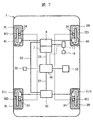
- FIG. 7 is a diagram showing a modified example of FIG.
- the differences from FIG. 1 are the rear wheel electric hydraulic pressure mechanism 50, the rear wheel side hydraulic disc brakes 51R and 51L, the front wheel side electric hydraulic pressure mechanism 6 and the rear wheel electric hydraulic pressure mechanism 50. It is provided with a liquid pipe 52 to be connected.
- the braking force of the four front and rear wheels is controlled by using the electric hydraulic mechanism, and in addition, the braking force of the rear wheels can be controlled by the electric mechanism.
- a slip determination threshold value according to the operation amount of the brake pedal 16 is set in the same manner as described above.
- the brake pedal is not operated, the braking force by the electric mechanism is increased, and when the brake pedal is operated, it is possible to control so that the rear wheel slip does not increase, which is almost the same as the above-described embodiment. The same effect can be obtained.
- the backup brake is provided on the front wheel side, but it may be provided on the rear wheel side. That is, the backup brake is provided on at least one of the front wheels and the rear wheels, and when the brake mechanism of one system (electric hydraulic system) fails, it switches to the other system (hydraulic circuit system) and operates. All you need is. Then, at the time of backup braking, the slip determination threshold value of the wheel (front wheel or rear wheel) on the side where the backup brake is not operating is set based on the braking force information of the backup brake.
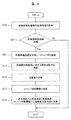
- FIG. 8 is a flowchart showing the control executed by the brake control device according to the second embodiment of the present invention, and corresponds to a modified example of the first embodiment.
- the control steps having the same contents as those in FIG. 6 are designated by the same reference numbers, and the description thereof will be omitted.
- step S21 is added instead of step S12 of the control flow shown in FIG.
- step S21 is executed after determining the failure in step S11.
- the average or smaller wheel speed of the two wheels may be set to vf.
- step S13 the required braking force calculation unit 41 of the brake control device 30 requests the rear wheel side braking mechanism 5 based on the slip ratio s and the command value Ft of the upper control device 33.
- the required braking force Fr is calculated.
- the process proceeds to step S14.
- the operation of the brake pedal 16 can be read by a stroke sensor or the like, but as in the second embodiment (FIG. 8), the slip ratio calculated from the front wheel speed is used instead of the stroke sensor information.
- the driver's backup brake operation amount may be read. That is, in the second embodiment, the backup brake operation amount (braking force information) is calculated based on the slip ratio calculated from the speed of the vehicle and the speed of the front wheels. After the failure of the front wheel side braking mechanism 4, the increase in slip ratio is due to the operation of the backup brake by the driver's operation of the brake pedal 16, except for the engine brake and the like.
- the slip determination threshold of the rear wheel brake is changed based on the slip ratio as in the second embodiment instead of the brake pedal operation amount of the first embodiment, if the backup brake is not operated, it is electrically operated. It is possible to increase the braking force by the mechanism and control so as to suppress the slip of the rear wheels when the backup brake is operated, and almost the same effect as that of the first embodiment described above can be obtained.
- FIG. 9 is a block diagram showing the control executed by the brake control device 30 according to the third embodiment of the present invention
- FIG. 10 is a flowchart showing the control executed by the brake control device 30 according to the third embodiment of the present invention. Yes, it corresponds to a modified example of the first embodiment.
- the control steps having the same contents as those in FIG. 6 are designated by the same reference numbers, and the description thereof will be omitted.
- the block diagram of the third embodiment shown in FIG. 9 is different from the block diagram (FIG. 4) of the first embodiment in that the backup brake operation amount calculation unit 45 is added.
- step S31 is executed after determining the failure in step S11.
- step S31 the brake control device 30 acquires the front-rear acceleration Av of the vehicle and the braking force Fr generated by the rear wheel side braking mechanism 5.
- the braking force Fr generated by the rear wheel side braking mechanism 5 is calculated based on the operating amount of the electric disc brakes 5R and 5L.
- step S32 the process proceeds to step S32.
- step S32 the backup brake operation amount calculation unit 45 of the brake control device 30 calculates the backup brake operation amount Fb from the front-rear acceleration Av of the vehicle and the braking force Fr generated by the rear wheel side braking mechanism 5.
- the backup brake operation amount calculation unit 45 of the brake control device 30 calculates the backup brake operation amount Fb from the front-rear acceleration Av of the vehicle and the braking force Fr generated by the rear wheel side braking mechanism 5.
- the vehicle body weight Mv
- Fr MvAv-Fr.
- the operation of the brake pedal 16 can be read by a stroke sensor or the like, but as in the third embodiment, the driver's backup brake is based on the slip ratio obtained from the front wheel speed instead of the stroke sensor information. The operation amount may be read. After the failure of the front wheel side braking mechanism 4, the increase in slip ratio is due to the operation of the backup brake by the driver's operation of the brake pedal 16, except for the engine brake and the like.
- a backup brake is used when a part of the control brake function fails.
- control for obtaining a large deceleration can be performed, and when the backup brake is operated, control for improving running stability can be performed.
- stroke simulator 19 ... electromagnetic stroke simulator valve, 20 ... Master cylinder pressure sensor, 21 ... Pump pressure sensor, 22R, 22L ... Caliper pressure sensor, 23 ... Control signal line, 24 ... Rear wheel side electric mechanism, 25R, 25L ... Brake electric motor, 26 ... Brake pad, 27 ... Rotation / linear motion conversion mechanism, 29R, 29L ... thrust sensor, 30 ... brake control device, 33 ... higher control device, 34 ... wheel rotation speed sensor, 35 ... vehicle motion sensor, 41 ... required braking force calculation unit, 42 ... speed Difference calculation unit, 43 ... Slip judgment threshold setting unit, 44 ... Braking force adjustment unit, 45 ... Backup brake operation amount calculation unit.
Landscapes
- Engineering & Computer Science (AREA)
- Transportation (AREA)
- Mechanical Engineering (AREA)
- Physics & Mathematics (AREA)
- Fluid Mechanics (AREA)
- Microelectronics & Electronic Packaging (AREA)
- Regulating Braking Force (AREA)
- Valves And Accessory Devices For Braking Systems (AREA)
Abstract
本発明の課題は、バックアップブレーキを備えたものにおいて、減速度の確保と車両走行安定性を両立することができるブレーキ制御装置を提供することである。 本発明は、前輪側電動液圧機構6と液圧回路系統とを備え、前輪2L,2Rに制動力を与える前輪側制動機構4と、前記後輪側に制動を与える後輪側制動機構5と、前記前輪側電動液圧機構6が失陥した時に液圧回路系統15に切り替えて作動し、前輪2R,2Lに制動力を与えるバックアップブレーキと、スリップ判断閾値を設定するスリップ判断閾値設定部43と、を備える。 スリップ判断閾値設定部43は、前記バックアップブレーキの作動時に前記バックアップブレーキの制動力情報に基づいて後輪3L,3Rの前記スリップ判断閾値を設定する。
Description
本発明は、車両に搭載されるブレーキ制御装置に関する。
車両に搭載されるブレーキ装置は、車両の前輪と後輪が別系統の配管で接続されている。従来、前輪と後輪の制動系統が正常であれば、後輪は左右輪のうちどちらかロックし易い側を基準に左右両輪のブレーキ液圧を同時に制御する。また、前輪の制動系統に欠陥が生じた場合には、後輪は左右輪のうちどちらかロック傾向を示していない車輪に合わせて制御を行うようにして後輪の制動力を高めるようにしている。このような技術として、例えば特許文献1に記載の技術が提案されている。
ところで、特許文献1に記載されたような前輪と後輪が別系統の配管で接続されたブレーキ装置とは異なり、前輪側を電動液圧機構、後輪側を電動機構としたブレーキ装置がある。このような装置では、前輪側のポンプとバルブで構成された電動液圧機構とブレーキペダルとの間の液圧による機械的な接続は、液圧機構とブレーキペダルをつなぐバルブを閉止することによって通常時は切り離されている。この場合、ブレーキペダルのストロークまたは踏力センサ信号に基づいて演算される要求制動力や、ブレーキ制御装置の上位に設けられた車両制御装置からの要求制動力などの制御量に基づいて前輪側の電動液圧機構と後輪側の電動機構を制御する。
また、前輪の電動液圧機構が故障した場合、液圧機構内のバルブを開放して前輪側にあるブレーキキャリパとブレーキペダルとを直接液圧で接続される。この際にドライバのペダル操作に応じた電動機構によるアシストのないブレーキ制動力が前輪に発生し、電動液圧機構における電動機構の部分が故障した際のバックアップブレーキとしての役割を果たす。このときに、後輪側の電動機構の制御機能が残存する場合はドライバのペダル操作量に基づいて後輪の制動力を制御する。
特許文献1に記載の技術においては、ブレーキ装置の一部機能が故障した際に作動するバックアップブレーキを備えたブレーキ装置の制御方法については考慮されていなかった。特許文献1では、前輪の制動系統に欠陥が生じた場合には、後輪は左右輪のうちどちらかロック傾向を示していない車輪に合わせて制御を行うようにして後輪の制動力を高めるようにしているので、後輪がロックし、車両の走行安定性が低下する可能性があった。
本発明の目的は、ブレーキ装置の一部機能が故障した際に作動するバックアップブレーキを備えたものにおいて、減速度の確保と車両走行安定性を両立することができるブレーキ制御装置を提供することにある。
上記課題を解決するために、本発明は、車両の前輪と後輪の制動力を制御するブレーキ制御装置であって、前記前輪もしくは前記後輪の少なくとも一方に備えられ、一の系統のブレーキ機構が失陥した時に他の系統に切り替えて作動するバックアップブレーキと、スリップ判断閾値を設定するスリップ判断閾値設定部と、を備え、前記スリップ判断閾値設定部は、前記バックアップブレーキの作動時に前記バックアップブレーキの制動力情報に基づいて前記スリップ判断閾値を設定することを特徴とする。
本発明によれば、バックアップブレーキを備えたものにおいて、減速度の確保と車両走行安定性を両立することができるブレーキ制御装置を提供することができる。
以下、本発明の実施例について図面を用いて詳細に説明する。なお、各図面において、同一の構成については同一の符号を付し、重複する部分についてはその詳細な説明は省略する。また、本発明は以下の実施形態に限定されることなく、本発明の技術的な概念の中で種々の変形例や応用例をもその範囲に含むものである。
図1から図6を参照して、本発明の第1実施例に係る車両のブレーキシステムとその制御方法について説明する。図1は本発明の第1実施例に係る車両のブレーキ装置の概略構成を示す図、図2,図3は図1における前輪側と後輪側のそれぞれの制動機構の概略構成を示している。図4は本発明の第1実施例に係るブレーキ制御装置30で実行される制御を示すブロック図であり、図5はその制御フローを示すフローチャートである。図6は図5に示す制御方法によるブレーキペダル16操作量変化と車両速度、後輪車輪速とスリップ判断閾値の関係を示す。
図1において、車両1は一対の前輪2R,2Lと、一対の後輪3R,3Lと、を備え、また、前輪2R,2Lに対して制動力を付与する前輪側制動機構4(図2参照)と、後輪3R,3Lに対して制動力を付与する後輪側制動機構5(図3参照)を備えている。
第1実施例においては、前輪側制動機構4は、ブレーキ液圧で動作してブレーキディスクBDを挟み込む液圧ディスクブレーキ(液圧ブレーキ機構)4R,4Lと、ブレーキ液圧を生成する前輪側電動液圧機構6と、前輪側制動制御装置7と、から構成されている。
また、後輪側制動機構5は、ブレーキ用電動モータ25R,25Lの回転によって動作してブレーキディスクBDを挟み込む電動ディスクブレーキ(電動ブレーキ機構)5R,5Lと、ブレーキ用電動モータ25R,25Lと、から構成されている。
さらに、前輪側制動制御装置7とブレーキ用電動モータ25R,25Lを制御し、車両1が発生する制動力を調整するブレーキ制御装置30を備えている。
前輪側電動液圧機構6は、例えば図2に示すように、電動部品要素であるポンプ用電動モータ8で駆動され、リザーバタンク9内のブレーキ液を加圧する液圧源である液圧ポンプ10と、液圧ポンプ10のブレーキ液圧を調整する電磁調圧弁11と、液圧ディスクブレーキ4R,4Lに流入するブレーキ液を調整する電磁流入弁12R,12Lと、流出するブレーキ液を調整する電磁流出弁13R,13Lと、ブレーキペダル16側を遮断する電磁遮断弁14等の電動部品要素で構成された液圧回路系統15を備えている。なお、第1実施例の図2では、電動液圧系統となる前輪側電動液圧機構6と液圧回路系統15は同じ枠で囲っている。
さらに、図2に示す前輪側制動機構4は、前輪側電動液圧機構6とは別に運転者が操作するブレーキペダル16の操作を動力源として動作するマスタシリンダ17を有している。マスタシリンダ17は液圧回路系統15によって液圧ディスクブレーキ4R,4Lと接続されており、電磁遮断弁14と電磁流入弁12R,12Lを開弁状態とし、電磁流出弁13R,13Lを閉弁状態にすることで、マスタシリンダ17で生成されたブレーキ液圧により液圧ディスクブレーキ4R,4Lを動作させて、車両1を制動することが可能である。
また、液圧回路系統15の途中にマスタシリンダ圧力センサ20、液圧ポンプ10の吐出側にポンプ圧力センサ21、液圧ディスクブレーキ4R,4Lに向かう液圧回路の途中にキャリパ圧力センサ22R,22Lがそれぞれ取り付けられ、液圧回路各部の液圧を検出可能である。
また、液圧回路系統15には、電磁遮断弁14が閉弁状態の時にブレーキペダル16の操作に対して、適切な反力を運転者に与え、マスタシリンダ17から吐出されるブレーキ液圧を吸収するためにストロークシミュレータ18を備えている。
さらに、ストロークシミュレータ18に至る液圧回路系統15には、ストロークシミュレータ18へのブレーキ液の流入、流出を調整する電磁ストロークシミュレータ弁19も備えられている。
前輪側制動機構4のうち、電動部品要素である、ポンプ用電動モータ8、電磁液圧制御弁として機能する電磁調圧弁11、電磁流入弁12R,12L、電磁流出弁13R,13L、電磁遮断弁14、電磁ストロークシミュレータ弁19は、前輪側制動制御装置7で制御される。
前輪側制動制御装置7には制御信号線23が接続されている。制御信号線23はブレーキ制御装置30(図1参照)から各車輪の液圧指令値などの制御指令情報を前輪側制動制御装置7に入力し、前輪側制動機構4のポンプ用電動モータ8の電流値や液圧回路各部の圧力などの駆動状態情報をブレーキ制御装置30に出力する役割を果たす。
また、第1実施例において、後輪側制動機構5は電動ディスクブレーキ5R,5Lを備えている。ここで、電動ディスクブレーキ5R,5Lは同じ構成とされており、例えば、図3に示すように、後輪側電動機構24は、ブレーキ用電動モータ25R,25Lによってブレーキパッド26をブレーキディスクBDに押し付け、押圧力を生成して制動力を発生させている。ブレーキ用電動モータ25R,25Lの回転力は、回転/直動変換機構27によって直動運動に変換されて、ブレーキパッド26をブレーキディスクBDに押し付けて制動力を付与している。ここで、回転/直動変換機構27は、例えば送りねじ機構を採用して、回転運動を直動運動に変換している。
また、後輪側電動機構24は推力センサ29R,29Lを備えており、ブレーキ制御装置30は推力センサ29R,29Lで検出される押圧力に基づいてブレーキ用電動モータ25R,25Lの回転を制御し、ブレーキパッド26の押圧力を調整する。後輪側電動機構24とブレーキ制御装置30は、制御信号線23によって接続されている。
さらに、制御信号線23はブレーキ制御装置30から制御指令情報をブレーキ用電動モータ25R,25Lに入力し、後輪側制動機構5の押圧力やブレーキ用電動モータ25R,25Lの電流値などの駆動状態情報をブレーキ制御装置30に出力する役割を果たす。
図1に戻って、ブレーキペダル16の操作量(ブレーキペダルのストローク、踏力等)は、制動力情報としてブレーキ制御装置30に送信される。また、車両1の前輪2R,2Lと後輪3R,3Lには車輪回転速度センサ34が取り付けられており、車輪速度情報をブレーキ制御装置30に送信している。また、車両運動センサ35も車両1の加速度、ヨーレイトなどの車両挙動情報を検出し、ブレーキ制御装置30に送信している。
これに加えて、車両1には、上位制御装置33を備えている。上位制御装置33は、カメラ、レーダ等からの外界情報、ナビゲーションシステムからの地図情報、車両1に備えられた駆動装置、操舵装置、ブレーキ装置等の動作状態情報、車両1の運動状態情報等の1つ以上の情報に基づき、車両1の適切な制動動作量を演算し、この車両制動量を制御指令情報としてブレーキ制御装置30に送信する。また、上位制御装置33は、レーダ、ナビゲーションシステムのGPS機能から車両速度を得て、ブレーキ制御装置30に送信する。
このような車両1に搭載されたブレーキ制御装置30においては、運転者によるブレーキペダル16のストロークやマスタシリンダ圧力センサ20などから得られる操作情報、車輪回転速度センサ34から得られる前後輪の車輪速度情報、車両運動センサ35から得られる車両1の車両挙動情報、上位制御装置33の制御指令情報に基づいて、前輪側制動制御装置7とブレーキ用電動モータ25R,25Lに制御指令を送信し、前輪側制動機構4、後輪側制動機構5の動作を制御している。
第1実施例の場合、通常制御時に前輪側制動機構4は、電磁遮断弁14を閉弁することにより、マスタシリンダ17と液圧ディスクブレーキ4R,4Lの接続を遮断し、電磁ストロークシミュレータ弁19を開放して運転者のブレーキペダル16の操作により吐出されたブレーキ液圧を吸収する。
同時にブレーキペダル16の操作情報、車両1の車輪速度情報や車両挙動情報、上位制御装置33の制御指令情報、後輪3R,3L側の電動ディスクブレーキ5R,5Lの動作状態情報等に基づいて、ブレーキ制御装置30は前輪2R,2Lと後輪3R,3Lで発生させる制動力に対応した制御量を演算し、前輪側制動制御装置7とブレーキ用電動モータ25R,25Lに送信する。
そして、前輪側制動機構4の前輪側制動制御装置7は、ブレーキ制御装置30の制御量指令値に基づいて、ポンプ用電動モータ8、及び電磁調圧弁11、電磁流入弁12R,12L、電磁流出弁13R,13Lの動作を制御して、液圧ディスクブレーキ4R,4Lで制動力を発生させる。
一方、後輪側制動機構5は、ブレーキ制御装置30の制御量指令値に基づいて、ブレーキ用電動モータ25R,25Lの動作を制御して、電動ディスクブレーキ5R,5Lの制動力を調整している。
次に、このブレーキ装置において、前輪側制動機構4の一部が故障した場合の動作について説明する。前輪側制動機構4の一部が故障した場合は、前輪側制動制御装置7に備えられたリレーを遮断するなどの対応によりバックアップブレーキモードに移行する。バックアップブレーキモードでは、電磁遮断弁14と電磁流入弁12R,12Lを開弁状態、電磁流出弁13R,13Lを閉弁状態にすることでブレーキペダル16を操作するドライバの踏力で直接液圧ディスクブレーキ4R,4Lを操作する。すなわち、バックアップブレーキは、一の系統のブレーキ機構が失陥した時に他の系統に切り替えて作動するものである。
故障時に即座にバックアップブレーキモードに移行するために、第1実施例では、非通電状態において電磁遮断弁14と電磁流入弁12R,12Lが開弁状態、電磁流出弁13R,13Lが閉弁状態になる弁を使う。前輪側制動機構4の一部が故障した場合も後輪側制動機構5が正常な場合、ドライバのブレーキペダル16操作情報や上位制御装置33の制御情報に基づいてブレーキ制御装置30により後輪側制動機構5が制御され、電動ディスクブレーキ5R,5Lにより制動力を発生する。
以上のような動作を行うブレーキ装置において、前輪側制動機構4が故障した場合に、バックアップブレーキの操作状態に応じてブレーキ制御装置30で行う制御について図4の制御ブロック図、及び図5の制御フローに基づいて説明する。図4は、第1実施例における前輪側制動機構4の一部が故障した際に実行される制御を実現するためにブレーキ制御装置30内に搭載される制御ブロック図の一例である。また、図5は、前輪側制動機構4の故障時にブレーキ制御装置30により行われる制御フロー図であり、所定時間毎に起動されるものとする。
〔ステップS10〕 先ず、ステップS10において、ブレーキ制御装置30は、前輪側制動機構4の故障情報を取得する。ブレーキ制御装置30は、例えばブレーキ制御装置30からの検査信号に対する応答や、前輪側制動制御装置7からのエラー情報などを元に前輪側制動機構4の故障情報を取得する。その後、ステップS11に移行する。
〔ステップS11〕 次に、ステップS11において、ブレーキ制御装置30は、前輪側制動機構4の故障を判定する。故障を判定した場合、前輪側制動制御装置7のリレーを遮断し、前輪側制動機構はバックアップブレーキモードになる。故障がない場合には本フローを終了し、故障した場合にはステップS12に移行する。
〔ステップS12〕 次に、ステップS12において、ブレーキ制御装置30は、ブレーキペダルの操作量Pfを取得する。ブレーキペダルの操作量は例えばペダルストロークや、ペダル踏力などにするとよい。その後、ステップS13に移行する。
〔ステップS13〕 次に、ステップS13において、ブレーキ制御装置30の要求制動力演算部41は、ブレーキペダルの操作量Pfや上位制御装置33の指令値Ftに基づいて後輪側制動機構5に対して要求する要求制動力Frを演算する。ここでFrはブレーキペダル操作量に対してFr=f1(Pf)のような関数で求め、上位制御装置33の指令値に対してFr=f2(Ft)のような関数で演算する値とする。その後、ステップS14に移行する。
〔ステップS14〕 次に、ステップS14において、ブレーキ制御装置30の速度差演算部42は、前輪側制動制御装置7を介して得た車両速度(車体速度),ブレーキペダルの操作量Pfから速度差Δvを演算する。速度差Δvとは車両速度(車体速度)とスリップ判断閾値vthとの差を示すものである。ここで、速度差ΔvはΔv=g(Pf)の関数で求められる値とする。関数gは例えばPf=0のときに速度差Δvが最も大きな値とし、Pfが大きくなるとΔvが小さくなる関数とするとよい。速度差Δvはブレーキペダルの操作量に応じて演算される値となる。その後、ステップS15に移行する。
〔ステップS15〕 次に、ステップS15において、ブレーキ制御装置30のスリップ判断閾値設定部43は、スリップ判断閾値vthを演算する。スリップ判断閾値vthは車両速度vcarと速度差Δvを用いて、vth=vcar-Δvのように求めるとよい。スリップ判断閾値vthは車両速度vcarよりも低い値であり、ブレーキペダルの操作量の応じた値だけ小さい値となる。車両速度vcarは例えば4輪の車輪速度から求めることにするとよい。例えば前輪と後輪の車輪速度に差がある場合には、車輪速度が速い方を車両速度vcarとするとよい。または、ナビゲーションシステムのGPS機能から車両速度vcarを得るようにしてもよい。スリップ判断閾値設定部43は、バックアップブレーキの作動時にバックアップブレーキの制動力情報に基づいてスリップ判断閾値vthを設定するものである。その後、ステップS16に移行する。
〔ステップS16〕 次に、ステップS16において、ブレーキ制御装置30の制動力調整部44は、後輪の電動ディスクブレーキ5R、5Lに対する後輪推力指令値を演算する。後輪推力指令値はスリップ判断閾値設定部43で演算されたスリップ判断閾値vthを後輪の各車輪の車輪速度が上回る場合は要求制動力演算部41で演算された要求制動力Frに基づいて演算される。一方、後輪の各車輪の車輪速度がスリップ判断閾値vthを下回る場合、後輪がスリップしつつあると判断して、制動力を減少させるため推力指令値を小さくする。
以上のような制御を行うブレーキ制御装置30を備えたブレーキ装置における失陥前後のブレーキペダル16の操作量と車両速度、車輪速度の時間変化を模式的に図6に示す。
図6は、図5に示す制御方法による制動時のブレーキペダル操作と車両速度、車輪速度、スリップ判断閾値の関係を示す図である。
図6は、図5に示す制御方法による制動時のブレーキペダル操作と車両速度、車輪速度、スリップ判断閾値の関係を示す図である。
図6の上図はドライバによるブレーキペダル16操作量を示し、下図が車両速度、後輪車輪速度、スリップ判断閾値の時間変化を示す。後輪は2輪あるため本来は2本の線で示すべきだが、第1実施例では本発明の内容の理解し易くするため1本の線で記載している。また、第1実施例では、カメラやレーダで障害物を検知し、車両速度、障害物の有無に応じて自動で車輪に制動をかける自動ブレーキを車両に搭載した例で説明する。
図6において、車両1は、開始時点で上位制御装置33からの指令で自動ブレーキが作動している状態にあり、時間t61で前輪側制動機構4の一部に故障が発生したと仮定して説明する。車両1は自動ブレーキの作動により車両速度が減速している。開始時点において、車両1には前輪及び後輪の全てに制動力が作用している。時間t61で前輪側制動機構に故障が発生し、ブレーキ制御装置30がステップS11(図5)により故障を検知すると、ステップS12で取得したブレーキペダル操作量Pfに基づき、ステップS13で後輪側制動機構5に対する要求制動力を演算する。ここで、前輪側制動機構4は故障により電力供給を遮断し、電磁遮断弁14と電磁流入弁12R,12Lが開弁状態、電磁流出弁13R,13Lが閉弁状態となり、バックアップブレーキの動作モードとなるが、ドライバがブレーキペダル16を操作していないため、前輪側制動機構4で発生する制動力はなくなる。すなわち、ドライバがブレーキペダル16を操作するまでの間は、後輪側制動機構5のみの制動力で減速している。そこで、ステップS13では後輪側制動機構5に対する要求制動力を大きく演算し、減速度の低下を防ぐ。同時に、ステップS14においてブレーキペダル16操作量に基づいて車両速度と後輪車輪速度の速度差Δvを演算する。時間t61の時点で、ブレーキペダル16は操作されていないため、速度差Δvは正常時よりも大きく演算される。スリップ判断閾値設定部43は、この速度差Δvに基づいてスリップ判断閾値を演算する(ステップS15)。これらの演算によって、時間t61で速度差Δvが拡張されたため、スリップ判断閾値が時間t61以前よりも低く設定される。後輪側制動機構5に対する要求制動力が大きく設定されたことにより、ステップS16において後輪による大きな制動力発生に伴う後輪車輪速度の低下に対してスリップ判断を行わない。そのため時間t61から時間t62の区間では後輪によって通常よりも大きな減速度を発生する。
換言すると、スリップ判断閾値設定部43は、自動ブレーキ作動中に前輪における一の系統のブレーキ機構が失陥した時、バックアップブレーキが制動力を発生していない場合には車両の速度との差が最も大きくなるようにスリップ判断閾値を設定する。逆にスリップ判断閾値設定部43は、バックアップブレーキによる制動力が発生した場合には車両の速度との差が小さくなるようにスリップ判断閾値を設定する。このようにスリップ判断閾値設定部43は、バックアップブレーキが制動力を発生していない場合、バックアップブレーキが制動力を発生している場合に比べ、車両の速度との差が大きくなるようにスリップ判断閾値を設定している。
時間t62からドライバがブレーキペダル16の操作を開始する。ブレーキペダル16の操作により液圧回路系統による前輪の制動が開始されると、前輪側に荷重が移動し、後輪側の荷重が小さくなるので、後輪車輪速が大きく低下する。この状態が継続されると後輪がロックし、車両が不安定となる。そこで第1実施例では、後輪のロックを抑制するために、ブレーキペダル16の操作量に応じて、スリップ判断閾値を変更する。スリップ判断閾値設定部43は、バックアップブレーキによる制動力が大きくなると、車両の速度との差が小さくなるようにスリップ判断閾値を設定する。このように、バックアップブレーキの制動力が大きいほど、後輪の制動力の緩和を開始した時点における車両の速度と後輪のスリップ判断閾値との差が小さくなる。
ステップS12で取得したブレーキペダル操作量に基づき、ステップS13で後輪側制動機構5に対する要求制動力を演算する。図4ではドライバが急激に大きなブレーキペダル操作をしたと仮定している。ステップS14でブレーキペダル操作量に基づいて速度差Δvを演算する。時間t62からt63の間はブレーキペダル操作量が漸増するため、速度差Δvもこれにあわせて減少する。そのため、ステップS15で演算されるスリップ判断閾値も上昇する。スリップ判断閾値は車両の速度に対し、ブレーキペダルの操作量の応じた値だけ小さい値としている。スリップ判断閾値設定部43は、バックアップブレーキによる制動力が大きくなると、車両の速度とスリップ判断閾値の差を小さくする。ブレーキペダルが踏まれると前輪が発生する制動力により減速度が増し前輪に荷重が移動する。
そのため、後輪で発生可能な制動力の上限が低下し、後輪の車輪速度も低下する。車輪速度低下がスリップ判断閾値を下回ると後輪の電動ディスクブレーキ5R、5Lに対する後輪推力指令値を減少させ車輪速を車両速度に近くなるまで車輪速度を復帰させる。後輪車輪速度が復帰すると再度後輪の電動ディスクブレーキ5R、5Lに対する後輪推力指令値を増加させ後輪による減速度の増加と共に後輪車輪速度が減少する。
そのため、後輪で発生可能な制動力の上限が低下し、後輪の車輪速度も低下する。車輪速度低下がスリップ判断閾値を下回ると後輪の電動ディスクブレーキ5R、5Lに対する後輪推力指令値を減少させ車輪速を車両速度に近くなるまで車輪速度を復帰させる。後輪車輪速度が復帰すると再度後輪の電動ディスクブレーキ5R、5Lに対する後輪推力指令値を増加させ後輪による減速度の増加と共に後輪車輪速度が減少する。
時間t63以降はブレーキペダル16が操作され続けるため、時間t61からt62の区間よりもスリップ判断閾値は高めに設定され、後輪車輪速度と車両速度の差が大きくならないようにする。
以上のような前輪側制動機構4故障時の処理を行うブレーキ制御装置30を備えた車両はドライバによるブレーキペダル操作量に応じた後輪の制動力制御が可能となる。そのため、自動運転中にドライバによるブレーキペダル操作がない場合には後輪による大きな制動力が得られる。一方で、ドライバによるブレーキペダル操作がある場合にはスリップ判断閾値を高くとるため、ドライバが急に大きな踏力でペダルを操作して、前輪で発生する制動力の急増による後輪荷重が減少した場合にも後輪のスリップは大きくならず、後輪がロックする可能性が低くなる。そのため、ドライバの急なブレーキペダル操作に対しても後輪ロックによる車両の走行安定性の低下を招くことがない。
また、第1実施例ではブレーキペダル16操作による液圧回路系統によって前輪のみ制動力が発生する構成を示したが、この構成に代えてブレーキペダル16操作による液圧回路系統によって前後輪に制動力が発生する構成としても先に説明した実施例とほぼ同等の効果が得られる。その変形例を図7に示す。図7は図1の変形例を示す図である。図7において、図1と異なるところは、後輪電動液圧機構50と、後輪側の液圧ディスクブレーキ51R,51Lと、前輪側電動液圧機構6と後輪電動液圧機構50とを接続する液配管52を備えたことにある。
図7の構成では、電動液圧機構を用いて前後4輪の制動力を制御し、これに加えて後輪は電動機構による制動力制御も可能としている。このような構成に対しても電動液圧機構が故障した場合に、先に述べたものと同様にブレーキペダル16操作量に応じたスリップ判断閾値を設定する。これによってブレーキペダル操作がない場合には、電動機構による制動力を大きくし、ブレーキペダル操作ある場合には後輪スリップが大きくならないように制御することが可能となり、先に説明した実施例とほぼ同等の効果が得られる。
第1実施例においては、前輪側にバックアップブレーキを設けるようにしたが、後輪側に設けるようにしても良い。すなわち、バックアップブレーキは、前輪もしくは後輪の少なくとも一方に備えられ、一の系統(電動液圧系統)のブレーキ機構が失陥した時に他の系統(液圧回路系統)に切り替えて作動するものであればよい。そして、バックアップブレーキ時には、バックアップブレーキの制動力情報に基づいて、バックアップブレーキが作動していない側の車輪(前輪もしくは後輪)のスリップ判断閾値を設定する。
次に図8を参照して、本発明の第2実施例に係る車両のブレーキシステムの制御方法について説明する。図8は本発明の第2実施例に係るブレーキ制御装置で実行される制御を示すフローチャートであり、第1実施例の変形例に相当する。なお、図6の制御ステップと同じ内容の制御ステップについては同じ参照番号を付し、その説明は省略する。
図8に示す第2実施例の制御フローは、図6に示す制御フローのステップS12の代わりにステップS21が追加されている点で、第1実施例と異なっている。第2実施例ではステップS11で故障を判断した後にステップS21を実行する。
〔ステップS21〕 ステップS21において、ブレーキ制御装置30は前輪車輪速度vfを取得し、車両速度Vを用いて前輪の車輪のスリップ率s=vf/Vにより求める。ここで、前輪は2輪あるため2輪の平均あるいはより小さいほうの車輪速度をvfとすると良い。その後、ステップS13に移行する。
〔ステップS13〕 次に、ステップS13において、ブレーキ制御装置30の要求制動力演算部41は、スリップ率sや上位制御装置33の指令値Ftに基づいて後輪側制動機構5に対して要求する要求制動力Frを演算する。ここでFrはスリップ率に対してFr=f1(s)のような関数で求め、上位制御装置33の指令値に対してFr=f2(Ft)のような関数で演算する値とする。その後、ステップS14に移行する。
第1実施例ではブレーキペダル16の操作をストロークセンサなどにより読み取れるものとしたが、第2実施例(図8)のようにストロークセンサの情報の代わりに前輪車輪速度から演算されるスリップ率を元にドライバのバックアップブレーキ操作量を読み取るようにしてもよい。すなわち、第2実施例では、バックアップブレーキ操作量(制動力情報)を車両の速度と、前輪の速度とから演算されたスリップ率に基づき算出している。前輪側制動機構4の故障後は、エンジンブレーキなどを除くと、スリップ率の増加はドライバのブレーキペダル16操作によるバックアップブレーキの作動によるものである。そのため、第1実施例のブレーキペダル操作量に代えて第2実施例のようにスリップ率に基づいて後輪ブレーキのスリップ判断閾値を変えることにしてもバックアップブレーキの操作がない場合には、電動機構による制動力を大きくし、バックアップブレーキの操作ある場合には後輪のスリップを抑制するように制御することが可能となり、先に説明した第1実施例とほぼ同等の効果が得られる。
次に図9及び図10を参照して、本発明の第3実施例に係る車両のブレーキシステムの制御方法について説明する。図9は本発明の第3実施例に係るブレーキ制御装置30で実行される制御を示すブロック図、図10は本発明の第3実施例に係るブレーキ制御装置で実行される制御を示すフローチャートであり、第1実施例の変形例に相当する。なお、図6の制御ステップと同じ内容の制御ステップについては同じ参照番号を付し、その説明は省略する。
図9に示す第3実施例のブロック図は、バックアップブレーキ操作量演算部45を追加した点で第1実施例のブロック図(図4)と異なっている。
また、図10に示す第3実施例の制御フローは、図5に示す制御フローのステップS12の代わりにステップS31とステップS32が追加されている点で、第1実施例と異なっている。第3実施例ではステップS11で故障を判断した後にステップS31を実行する。
〔ステップS31〕 ステップS31において、ブレーキ制御装置30は、車両の前後加速度Avと後輪側制動機構5で発生している制動力Frを取得する。後輪側制動機構5で発生する制動力Frは電動ディスクブレーキ5R,5Lの操作量に基づいて演算する。次にステップS32に移行する。
〔ステップS32〕 ステップS32において、ブレーキ制御装置30のバックアップブレーキ操作量演算部45は、車両の前後加速度Avと後輪側制動機構5で発生する制動力Frからバックアップブレーキ操作量Fbを演算する。例えば、車体重量をMvとした場合、Fb=MvAv-Frから演算すると良い。
第1実施例ではブレーキペダル16の操作をストロークセンサなどにより読み取れるものとしたが、第3実施例のようにストロークセンサの情報の代わりに前輪車輪速度から求められるスリップ率を元にドライバのバックアップブレーキ操作量を読み取ることにしてもよい。前輪側制動機構4の故障後は、エンジンブレーキなどを除くと、スリップ率の増加はドライバのブレーキペダル16操作によるバックアップブレーキの作動によるものである。そのため、第1実施例1のブレーキペダル操作量に代えて第3実施例のようにスリップ率に基づいて後輪ブレーキのスリップ判断閾値を変えることにしてもバックアップブレーキの操作がない場合には、電動機構による制動力を大きくし、バックアップブレーキの操作ある場合には後輪のスリップを抑制するように制御することが可能となり、先に説明した実施例とほぼ同等の効果が得られる。
以上説明したように本発明の各実施例によれば、前後輪を独立に制御可能な制御ブレーキ機能とバックアップブレーキ機能を備えた車両において、制御ブレーキ機能の一部が故障した際に、バックアップブレーキが操作されていない場合には大きな減速度を得る制御を行い、バックアップブレーキが操作されている際には走行安定性を高める制御を行うことができる。これにより、制御ブレーキ機能の一部が失陥した際の高い減速度と走行安定性の維持を両立できるブレーキ制御装置を提供することができる。
1…車両、2R,2L…(一対の)前輪、3R,3L…(一対の)後輪、4…前輪側制動機構、4R,4L…液圧ディスクブレーキ、5…後輪側制動機構、5R,5L…電動ディスクブレーキ、6…前輪側電動液圧機構、7…前輪側制動制御装置、8…ポンプ用電動モータ、9…リザーバタンク、10…液圧ポンプ、11…電磁調圧弁、12R,12L…電磁流入弁、13R,13L…電磁流出弁、14…電磁遮断弁、15…液圧回路系統、16…ブレーキペダル、17…マスタシリンダ、18…ストロークシミュレータ、19…電磁ストロークシミュレータ弁、20…マスタシリンダ圧力センサ、21…ポンプ圧力センサ、22R,22L…キャリパ圧力センサ、23…制御信号線、24…後輪側電動機構、25R,25L…ブレーキ用電動モータ、26…ブレーキパッド、27…回転/直動変換機構、29R,29L…推力センサ、30…ブレーキ制御装置、33…上位制御装置、34…車輪回転速度センサ、35…車両運動センサ、41…要求制動力演算部、42…速度差演算部、43…スリップ判断閾値設定部、44…制動力調整部、45…バックアップブレーキ操作量演算部。
Claims (10)
- 車両の前輪と後輪の制動力を制御するブレーキ制御装置であって、
前記前輪もしくは前記後輪の少なくとも一方に備えられ、一の系統のブレーキ機構が失陥した時に他の系統に切り替えて作動するバックアップブレーキと、
スリップ判断閾値を設定するスリップ判断閾値設定部と、を備え、
前記スリップ判断閾値設定部は、前記バックアップブレーキの作動時に前記バックアップブレーキの制動力情報に基づいて前記スリップ判断閾値を設定することを特徴とするブレーキ制御装置。 - 請求項1において、
前記バックアップブレーキはブレーキペダルの操作に応じて制動力が発生し、
前記スリップ判断閾値は前記車両の速度に対し、前記ブレーキペダルの操作量の応じた値だけ小さい値としたことを特徴とするブレーキ制御装置。 - 請求項1または2において、
前記スリップ判断閾値設定部は、前記バックアップブレーキによる制動力が大きくなると、前記車両の速度との差が小さくなるように前記スリップ判断閾値を設定することを特徴とするブレーキ制御装置。 - 請求項1または2において、
前記スリップ判断閾値設定部は、自動ブレーキ作動中に前記前輪または前記後輪の何れかにおける一の系統のブレーキ機構が失陥した時、前記バックアップブレーキが制動力を発生していない場合には前記車両の速度との差が最も大きくなるように前記スリップ判断閾値を設定し、前記バックアップブレーキによる制動力が発生した場合には前記車両の速度との差が小さくなるように前記スリップ判断閾値を設定することを特徴とするブレーキ制御装置。 - 請求項1または2において、
前記スリップ判断閾値設定部は、前記バックアップブレーキが制動力を発生していない場合、前記バックアップブレーキが制動力を発生している場合に比べ、前記車両の速度との差が大きくなるように前記スリップ判断閾値を設定することを特徴とするブレーキ制御装置。 - 請求項1または2において、
前記バックアップブレーキの制動力が大きいほど、前記前輪もしくは前記後輪の制動力の緩和を開始した時点における前記車両の速度と前記前輪もしくは前記後輪との前記スリップ判断閾値と差が小さくなることを特徴とするブレーキ制御装置。 - 請求項1において、
前記バックアップブレーキは、ドライバによるブレーキペダルの踏力で前記前輪もしくは前記後輪の何れか一方の車輪に制動力を付与することを特徴とするブレーキ制御装置。 - 請求項1または2において、
前記バックアップブレーキの制動力情報は、前記車両の速度と、前記前輪もしくは前記後輪の速度から演算されたスリップ率に基づいて算出することを特徴とするブレーキ制御装置。 - 請求項1または2において、
前記車両の前後加速度と、前記前輪または前記後輪の制動力とから前記バックアップブレーキの操作量を演算するバックアップブレーキ操作量演算部を備えたことを特徴とするブレーキ制御装置。 - 車両の前輪と後輪の制動力を制御するブレーキ制御装置であって、
電動液圧系統と液圧回路系統とを備え、前記前輪に制動力を与える前輪側制動機構と、前記後輪側に制動を与える後輪側制動機構と、
前記電動液圧系統が失陥した時に前記液圧回路系統に切り替えて作動し、前記前輪に制動力を与えるバックアップブレーキと、
前記車両の速度よりも低い値となるスリップ判断閾値を設定するスリップ判断閾値設定部と、
前記スリップ判断閾値と前記車両の車輪速度に応じて前記制動力を調節する制動力調整部と、を備え、
前記スリップ判断閾値設定部は、前記バックアップブレーキの作動時に前記バックアップブレーキの制動力情報に基づいて前記後輪の前記スリップ判断閾値を設定することを特徴とするブレーキ制御装置。
Priority Applications (4)
| Application Number | Priority Date | Filing Date | Title |
|---|---|---|---|
| KR1020217029619A KR102570368B1 (ko) | 2019-04-04 | 2020-03-18 | 브레이크 제어 장치 |
| CN202080019639.8A CN113613976B (zh) | 2019-04-04 | 2020-03-18 | 制动控制装置 |
| DE112020000908.4T DE112020000908T5 (de) | 2019-04-04 | 2020-03-18 | Bremssteuervorrichtung |
| US17/439,533 US11958462B2 (en) | 2019-04-04 | 2020-03-18 | Brake control apparatus |
Applications Claiming Priority (2)
| Application Number | Priority Date | Filing Date | Title |
|---|---|---|---|
| JP2019071900A JP7224226B2 (ja) | 2019-04-04 | 2019-04-04 | ブレーキ制御装置 |
| JP2019-071900 | 2019-04-04 |
Publications (1)
| Publication Number | Publication Date |
|---|---|
| WO2020203324A1 true WO2020203324A1 (ja) | 2020-10-08 |
Family
ID=72667881
Family Applications (1)
| Application Number | Title | Priority Date | Filing Date |
|---|---|---|---|
| PCT/JP2020/012136 Ceased WO2020203324A1 (ja) | 2019-04-04 | 2020-03-18 | ブレーキ制御装置 |
Country Status (6)
| Country | Link |
|---|---|
| US (1) | US11958462B2 (ja) |
| JP (1) | JP7224226B2 (ja) |
| KR (1) | KR102570368B1 (ja) |
| CN (1) | CN113613976B (ja) |
| DE (1) | DE112020000908T5 (ja) |
| WO (1) | WO2020203324A1 (ja) |
Families Citing this family (2)
| Publication number | Priority date | Publication date | Assignee | Title |
|---|---|---|---|---|
| JP7528723B2 (ja) * | 2020-10-30 | 2024-08-06 | 株式会社アドヴィックス | 車両用制動装置 |
| CN116494943A (zh) * | 2023-04-30 | 2023-07-28 | 华为数字能源技术有限公司 | 一种双重备份的车辆制动系统及车辆 |
Citations (5)
| Publication number | Priority date | Publication date | Assignee | Title |
|---|---|---|---|---|
| JPH0585336A (ja) * | 1991-09-26 | 1993-04-06 | Aisin Seiki Co Ltd | アンチスキツド装置 |
| JPH06227384A (ja) * | 1993-02-03 | 1994-08-16 | Nisshinbo Ind Inc | アンチスキッド制御方法 |
| JP2004268849A (ja) * | 2003-03-11 | 2004-09-30 | Toyota Motor Corp | アンチスキッド制御装置 |
| JP2010064652A (ja) * | 2008-09-11 | 2010-03-25 | Hitachi Ltd | ブレーキ制御システム |
| WO2014136891A1 (ja) * | 2013-03-06 | 2014-09-12 | 株式会社アドヴィックス | ブレーキ装置 |
Family Cites Families (10)
| Publication number | Priority date | Publication date | Assignee | Title |
|---|---|---|---|---|
| JP2880663B2 (ja) * | 1995-04-18 | 1999-04-12 | アイシン精機株式会社 | ブレーキ液圧制御装置 |
| JP4449117B2 (ja) * | 1999-09-21 | 2010-04-14 | 株式会社アドヴィックス | 制動力配分制御装置 |
| JP2004130851A (ja) * | 2002-10-08 | 2004-04-30 | Advics:Kk | ハイブリッド式車両スリップ防止装置 |
| CN1778598A (zh) | 2004-11-17 | 2006-05-31 | 丰田自动车株式会社 | 电动汽车及其控制方法 |
| WO2010113308A1 (ja) * | 2009-04-02 | 2010-10-07 | ボッシュ株式会社 | ブレーキ制御装置 |
| JP5123972B2 (ja) * | 2010-04-05 | 2013-01-23 | 本田技研工業株式会社 | 車両用ブレーキ装置および車両用ブレーキ装置の制御方法 |
| JP2015134545A (ja) * | 2014-01-17 | 2015-07-27 | トヨタ自動車株式会社 | ハイブリッド車両の制御装置 |
| DE102016208944A1 (de) * | 2016-05-24 | 2017-11-30 | Robert Bosch Gmbh | Verfahren zum Abbremsen eines Fahrzeugs mit hydraulischer Fahrzeugbremse und elektromechanischer Bremsvorrichtung |
| US10293799B2 (en) * | 2016-07-29 | 2019-05-21 | Ford Global Technologies, Llc | Methods for transitioning into reduced braking performance modes upon failure of a primary braking system |
| JP7249729B2 (ja) * | 2017-06-27 | 2023-03-31 | 日立Astemo株式会社 | ブレーキ装置 |
-
2019
- 2019-04-04 JP JP2019071900A patent/JP7224226B2/ja active Active
-
2020
- 2020-03-18 US US17/439,533 patent/US11958462B2/en active Active
- 2020-03-18 CN CN202080019639.8A patent/CN113613976B/zh active Active
- 2020-03-18 DE DE112020000908.4T patent/DE112020000908T5/de active Pending
- 2020-03-18 KR KR1020217029619A patent/KR102570368B1/ko active Active
- 2020-03-18 WO PCT/JP2020/012136 patent/WO2020203324A1/ja not_active Ceased
Patent Citations (5)
| Publication number | Priority date | Publication date | Assignee | Title |
|---|---|---|---|---|
| JPH0585336A (ja) * | 1991-09-26 | 1993-04-06 | Aisin Seiki Co Ltd | アンチスキツド装置 |
| JPH06227384A (ja) * | 1993-02-03 | 1994-08-16 | Nisshinbo Ind Inc | アンチスキッド制御方法 |
| JP2004268849A (ja) * | 2003-03-11 | 2004-09-30 | Toyota Motor Corp | アンチスキッド制御装置 |
| JP2010064652A (ja) * | 2008-09-11 | 2010-03-25 | Hitachi Ltd | ブレーキ制御システム |
| WO2014136891A1 (ja) * | 2013-03-06 | 2014-09-12 | 株式会社アドヴィックス | ブレーキ装置 |
Also Published As
| Publication number | Publication date |
|---|---|
| US20220153245A1 (en) | 2022-05-19 |
| JP7224226B2 (ja) | 2023-02-17 |
| CN113613976B (zh) | 2024-04-12 |
| KR20210126716A (ko) | 2021-10-20 |
| CN113613976A (zh) | 2021-11-05 |
| JP2020168966A (ja) | 2020-10-15 |
| KR102570368B1 (ko) | 2023-08-25 |
| DE112020000908T5 (de) | 2021-11-04 |
| US11958462B2 (en) | 2024-04-16 |
Similar Documents
| Publication | Publication Date | Title |
|---|---|---|
| JP6849822B2 (ja) | 電動倍力装置およびブレーキ制御装置 | |
| US12024150B2 (en) | Method and apparatus for vehicle braking | |
| JP4762283B2 (ja) | ブレーキ制御装置 | |
| CN103260968B (zh) | 车辆用制动装置 | |
| US6205375B1 (en) | Vehicle stability control apparatus | |
| KR20210142793A (ko) | 듀얼 엑츄에이터로 구성된 자율 주행 차량용 전동식 부스터 | |
| JP7727837B2 (ja) | 車両制御装置、車両制御方法および車両制御システム | |
| CN111344199B (zh) | 制动系统 | |
| CN113613976B (zh) | 制动控制装置 | |
| WO2020175419A1 (ja) | 車両制御装置 | |
| WO2019069681A1 (ja) | 自動車のブレーキシステム | |
| JP4678249B2 (ja) | 車両用ブレーキ装置 | |
| JPH06312655A (ja) | 自動ブレーキ装置の制御方法 | |
| JP3899621B2 (ja) | ペダルストロークシミュレータ付き車両ブレーキ装置 | |
| JP2009137459A (ja) | 車両運動制御システム | |
| US20240217492A1 (en) | Vehicle braking force control device | |
| JP4858110B2 (ja) | 車両制動力制御装置 | |
| JP2960986B2 (ja) | アンチスキッド制御装置 | |
| JP2025058650A (ja) | 制動制御装置 | |
| JP2020138657A (ja) | 制動制御装置 | |
| KR102651942B1 (ko) | Ars를 이용한 제동 어시스트방법 및 시스템 | |
| KR100429035B1 (ko) | 차량용 제동장치 | |
| JP2009143496A (ja) | 車両運動制御システム | |
| JP2000211491A (ja) | ブレ―キ制御装置 | |
| JPH09303435A (ja) | 電気自動車の液圧ブレーキ装置 |
Legal Events
| Date | Code | Title | Description |
|---|---|---|---|
| 121 | Ep: the epo has been informed by wipo that ep was designated in this application |
Ref document number: 20784859 Country of ref document: EP Kind code of ref document: A1 |
|
| ENP | Entry into the national phase |
Ref document number: 20217029619 Country of ref document: KR Kind code of ref document: A |
|
| 122 | Ep: pct application non-entry in european phase |
Ref document number: 20784859 Country of ref document: EP Kind code of ref document: A1 |