WO2020203293A1 - 電動機 - Google Patents
電動機 Download PDFInfo
- Publication number
- WO2020203293A1 WO2020203293A1 PCT/JP2020/011978 JP2020011978W WO2020203293A1 WO 2020203293 A1 WO2020203293 A1 WO 2020203293A1 JP 2020011978 W JP2020011978 W JP 2020011978W WO 2020203293 A1 WO2020203293 A1 WO 2020203293A1
- Authority
- WO
- WIPO (PCT)
- Prior art keywords
- electric motor
- axial direction
- peripheral side
- axial
- iron core
- Prior art date
- Legal status (The legal status is an assumption and is not a legal conclusion. Google has not performed a legal analysis and makes no representation as to the accuracy of the status listed.)
- Ceased
Links
Images









Classifications
-
- H—ELECTRICITY
- H02—GENERATION; CONVERSION OR DISTRIBUTION OF ELECTRIC POWER
- H02K—DYNAMO-ELECTRIC MACHINES
- H02K1/00—Details of the magnetic circuit
- H02K1/06—Details of the magnetic circuit characterised by the shape, form or construction
- H02K1/22—Rotating parts of the magnetic circuit
- H02K1/28—Means for mounting or fastening rotating magnetic parts on to, or to, the rotor structures
-
- H—ELECTRICITY
- H02—GENERATION; CONVERSION OR DISTRIBUTION OF ELECTRIC POWER
- H02K—DYNAMO-ELECTRIC MACHINES
- H02K11/00—Structural association of dynamo-electric machines with electric components or with devices for shielding, monitoring or protection
- H02K11/30—Structural association with control circuits or drive circuits
-
- H—ELECTRICITY
- H02—GENERATION; CONVERSION OR DISTRIBUTION OF ELECTRIC POWER
- H02K—DYNAMO-ELECTRIC MACHINES
- H02K5/00—Casings; Enclosures; Supports
- H02K5/04—Casings or enclosures characterised by the shape, form or construction thereof
- H02K5/18—Casings or enclosures characterised by the shape, form or construction thereof with ribs or fins for improving heat transfer
-
- H—ELECTRICITY
- H02—GENERATION; CONVERSION OR DISTRIBUTION OF ELECTRIC POWER
- H02K—DYNAMO-ELECTRIC MACHINES
- H02K9/00—Arrangements for cooling or ventilating
- H02K9/02—Arrangements for cooling or ventilating by ambient air flowing through the machine
Definitions
- the present invention relates to an electric motor having a bracket integrally provided with a heat sink.
- an inner rotor type permanent magnet electric motor in which a rotor having a permanent magnet is rotatably arranged inside a stator that generates a rotating magnetic field is known.
- This permanent magnet electric motor is used, for example, for rotationally driving a blower fan mounted on an air conditioner.
- an aluminum heat sink (radiating fin) is attached to the outer surface of a metal bracket that closes an opening provided on the opposite output side of a cylindrical resin (motor outer shell).
- a metal bracket that closes an opening provided on the opposite output side of a cylindrical resin (motor outer shell).
- the metal bracket and the heat radiation fin are separate parts, so the manufacturing cost has increased.
- the thermal resistance when heat is transferred from the metal bracket, which is a separate component, to the heat dissipation fins is large, and there is a limit to improving the heat dissipation of the heat generated in the electric motor.
- the problem that the electric motor becomes larger in the axial direction due to the increase in the number of connected parts and the work of connecting the parts (for example, screwing) are also required.
- an object of the present invention is to provide an electric motor that is miniaturized in the axial direction and has improved heat dissipation.
- one aspect of the electric motor of the present invention is a cylindrical motor outer shell having an opening on one end surface in the axial direction, and a coil and a stator integrally formed with the motor outer shell.
- a stator having an iron core, a rotor arranged inside the stator, and a circuit board arranged inside the outer shell of the motor are provided.
- the electric motor includes a heat sink attached to the outer shell of the motor so as to close the opening on one end surface of the motor.
- the heat sink has a plurality of heat radiation fins erected outward on the outer surface on one side in the axial direction, and the inner surface on the other side in the axial direction faces the circuit board. Is placed.
- the size is reduced in the axial direction and the heat dissipation is improved.
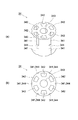
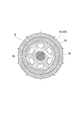
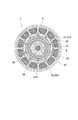
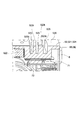
- FIG. 6 is a cross-sectional view taken along the line AA of FIG.
- FIG. 6 is a cross-sectional view taken along the line BB of FIG.
- FIG. 7 is a cross-sectional view taken along the line CC of FIG.
- FIG. 7 is a sectional view taken along line DD of FIG.
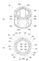
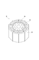
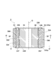
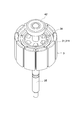
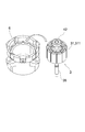
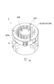
- It is a perspective view of the rotor, the shaft and the 2nd bearing of the permanent magnet electric motor which concerns on this invention. It is sectional drawing which shows the permanent magnet electric motor which concerns on this invention. It is the back side perspective view (a) and the front side perspective view (b) of the stator of the permanent magnet electric motor which concerns on this invention. It is a perspective view which shows the state before the rotor of FIG. 11 is combined with the stator of FIG.
- FIG. 11 It is a perspective view which shows the state after the rotor of FIG. 11 is combined with the stator of FIG. It is a front side perspective view (a) and the back side side perspective view (b) of the 2nd bracket of the permanent magnet electric motor which concerns on this invention. It is a perspective view of the permanent magnet electric motor which concerns on this invention. It is a partial cross-sectional view of the upper outer diameter side of FIG. It is a partially enlarged view on the left side of FIG.
- the permanent magnet electric motor 1 is, for example, a brushless DC motor.
- the electric motor 1 is used, for example, to rotationally drive a blower fan mounted on an outdoor unit of an air conditioner, and is screwed to the outdoor unit (not shown).
- an inner rotor type permanent magnet electric motor 1 in which a rotor 3 having a permanent magnet 31 is rotatably arranged inside a stator 2 that generates a rotating magnetic field will be described as an example.
- the permanent magnet electric motor 1 in the present embodiment includes a stator (stator) 2, a rotor (rotor) 3, and a motor outer shell 6.
- a circuit board 72 for controlling the electric motor 1 is arranged inside the motor outer shell 6.
- the stator 2 is provided via a stator core 21 having a cylindrical yoke portion and a plurality of teeth portions extending from the yoke portion to the inner diameter side, and an insulator 22.
- a winding (coil) 23 wound around the teeth portion is provided.
- the stator 2 is covered with a cylindrical motor outer shell 6 made of resin, except for the inner peripheral surface of the stator core 21.
- the motor outer shell 6 has an opening 6O (see FIG. 13A) formed on an end surface on the opposite output side (end surface 6S on one side in the axial direction) in the direction of the central axis O (hereinafter, axial direction). ..
- the electric motor 1, the stator 2, the insulator 22, the rotor 3, and the central axis O of the shaft 35 all match.
- the rotor 3 is rotatably arranged with a predetermined gap on the inner peripheral side of the stator core 21 of the stator 2.
- the rotor 3 is a surface magnet type in which permanent magnets 31 are arranged in an annular shape on the outer peripheral surface facing the stator core 21.
- the permanent magnet 31 is fixed around the shaft 35 via the outer peripheral side iron core 32, the insulating member 33, and the inner peripheral side iron core 34, which will be described later (see FIG. 11).
- the shaft 35 is supported by a first bearing 41 and a second bearing 42, the first bearing 41 is supported by the first bracket 51, and the second bearing 42 is supported by the second bracket 52. By doing so, the rotor 3 is rotatably supported.
- the second bearing 42 rotatably supports one end (counter-output side) of the shaft 35 of the rotor 3.
- the first bearing 41 rotatably supports the other end (output side) of the shaft 35 of the rotor 3.
- ball bearings are used as the first bearing 41 and the second bearing 42.
- the first bracket 51 is made of metal (steel plate, aluminum, etc.) and is arranged on one end side of the motor outer shell 6 in the axial direction, that is, on the output side of the shaft 35.
- the first bracket 51 has a first bearing accommodating portion 511 for accommodating the first bearing 41, and a flange portion 512 extending around from the open end of the first bearing accommodating portion 511.
- the first bearing accommodating portion 511 is formed in a cylindrical shape having a bottom having a through hole for passing the shaft 35, and the flange portion 512 of the first bracket 51 is insert-molded at the time of molding the motor outer shell 6, and the motor is formed. It is integrated with the outer shell 6.
- the outer ring of the first bearing 41 is press-fitted into the inner surface of the first bearing accommodating portion 511, and the output side of the shaft 35 supported by the inner ring of the first bearing 41 is formed in the center of the bottom portion of the first bearing accommodating portion 511. It protrudes to the outside from the through hole.
- the second bracket (heat sink) 52 is made of metal (steel plate, aluminum, etc.), and as shown in FIGS. 1, 16 to 18, the other end side of the motor outer shell 6 in the axial direction, that is, the opposite side of the shaft 35. It is fixed on the output side. As shown in FIG. 16, the second bracket 52 is formed in a substantially disk shape.
- the second bracket 52 includes a disk-shaped bracket main body 521, a flange portion 524 (outer edge portion 520) formed so as to extend in the outer diameter direction from one end in the axial direction of the bracket main body 521, and a second bearing 42. Has a second bearing accommodating portion 522 for accommodating and positioning.
- the bracket main body 521 is press-fitted into the opening 6O of the motor outer shell 6, and the flange portion 524 is in contact with one end surface 6S (outer edge portion 6E of the motor outer shell 6) of the motor outer shell 6. There is.
- the bracket main body 521 is attached to the motor outer shell 6 so as to close the opening 6O provided on one end surface 6S of the motor outer shell 6 by screwing the flange portion 524 to the outer edge portion 6E of the motor outer shell 6. It is attached.
- the second bearing accommodating portion 522 is formed as a hole having a circular bottom surface provided in the central portion of the bracket main body portion 521 so as to be recessed from the motor outer shell 6 side (output side of the shaft 35). In the present embodiment, the bearing 522 is arranged on the opening 6O side of the stator 2.
- the first bearing 41 is housed in the first bearing accommodating portion 511 provided in the first bracket 51, and the second bearing 42 is accommodated in the second bearing accommodating portion 522 provided in the second bracket 52.
- the first bearing 41 and the first bearing accommodating portion 511, and the second bearing 42 and the second bearing accommodating portion 522 are electrically conductive, respectively.
- the second bracket 52 functions not only as a bracket for closing the opening 6O provided in the end surface 6S on one side of the motor outer shell 6, but also as a heat sink in the present embodiment, and has a counter-output of the shaft 35.
- a heat radiating fin 523 erected toward the outside is provided on the side (outer surface).
- the second bracket 52 includes a plurality of grooves 525 provided so as to be recessed from the outer surface of the second bracket 52 toward the output side (inner surface) of the shaft 35 in the axial direction.
- heat radiation fins 523 are formed between adjacent grooves 525. Further, as shown in FIG.
- the groove 525 in the present embodiment has a shape in which a plurality of linear grooves 525 are arranged in parallel.
- the pattern of the shape drawn by these plurality of grooves 525 on the outer surface of the second bracket 52 is arbitrary.
- the groove 525 may be formed so as to extend radially from the central axis O.
- the heat radiating fin 523 may be provided with a contact portion 523a to which a drawing pin for removing the second bracket 52 from the mold is applied when the second bracket 52 (heat sink) is die-cast. ..
- the contact portion 523a integrated with the heat radiation fin 523 is arranged on the same circumference centered on the central axis O.
- the second bracket 52 which is the heat sink in the present embodiment, is integrally provided with the heat radiation fins 523 at a position between the second bearing accommodating portion 522 and the outer edge portion 520 in the radial direction.
- the heat radiation fins 523 do not overlap in the axial direction with the outer edge portion 520 connecting the second bracket 52 and the motor outer shell 6 and the second bearing accommodating portion 522 accommodating the second bearing 42. Since it can be arranged, it is possible to prevent the second bracket from becoming large in the axial direction, and it is possible to save space in the electric motor 1.
- the output side (inner surface) of the shaft 35 of the second bracket 52 which is a heat sink, is arranged to face the circuit board 72 and is in contact with the circuit board 72 via the heat transfer member 71.
- the heat generated in the circuit board 72 is transferred to the second bracket 52, which is an aluminum heat sink, as compared with the case where a metal bracket is provided as a separate component between the heat sink and the circuit board (not shown). Since it is transmitted directly, the thermal resistance can be reduced and the heat dissipation is improved.
- the base end portion 523b of the heat radiation fin 523 is located on the other side (inner surface side) in the axial direction from the end surface 6S (outer edge portion 6E) on one side of the motor outer shell 6 in the axial direction. ..
- the base end portion 523b of the heat radiation fin 523 is located on the other side (inner surface side) in the axial direction from the outer edge portion 520 (flange portion 524) of the second bracket 52.
- the tip portion 523t of the heat radiating fin 523 is formed so as not to be located outside the outer edge portion 520 (flange portion 524) (on the opposite output side of the shaft 35, that is, on one side in the axial direction) in the axial direction. There is. That is, the tip portion 523t of the heat radiation fin 523 is located on the inner surface side (the output side of the shaft 35, that is, the other side in the axial direction) or flush with the flange portion 524 with respect to the flange portion 524 in the axial direction.
- the heat radiating fin 523 is arranged on the inner peripheral side of the outer edge portion 520 (flange portion 524) in the radial direction of the rotor 3.
- the second bracket 52 includes an annular portion 52a formed around the heat radiation fin 523.
- the annular portion 52a connects the plurality of heat radiation fins 523 to each other (see FIG. 16A).
- the outer edge portion 520 includes an annular portion 52a and a flange portion 524 located on the outer peripheral side of the annular portion 52a, and the outer edge portion 520 has a plurality of holes for screwing to the flange portion 524. Has.
- the outer diameter side of the heat radiation fin 523 is surrounded by the annular portion 52a (and the flange portion 524), so that external force is prevented from being directly applied to the heat radiation fin 523 (for example, when screwing), and the heat radiation fin 523 is damaged. Can be prevented. Further, since the plurality of heat radiation fins 523 are connected to each other via the annular portion 52a, the strength of the heat radiation fins 523 can be increased.
- the second bracket 52 is formed, for example, by integrally molding aluminum die-cast. That is, the annular portion 52a is integrally formed with the flange portion 524 and the heat radiation fin 523. As a result, the strength of the annular portion 52a and the heat radiation fin 523 can be increased.
- the rotor 3 has a permanent magnet 31, an outer peripheral side iron core 32, an insulating member (connecting portion) 33, and an inner peripheral side iron core 34 from the outer diameter side to the inner diameter side. And the shaft 35 is provided.
- the permanent magnet 31 is annular with a plurality of (for example, 8 or 10) permanent magnet pieces 311 so that the north and south poles appear alternately at equal intervals in the circumferential direction. Is formed in.
- a plastic magnet formed in an annular shape by solidifying the magnet powder with a resin may be used.
- the outer peripheral side iron core 32 is formed in an annular shape as shown in FIG. 2, and is located on the inner diameter side of the permanent magnet 31 as shown in FIGS. 11 and 12.
- the outer peripheral side iron core 32 is recessed from the inner peripheral surface (see FIG. 2) to the outer diameter side in order to secure the function of preventing rotation with the insulating member 33 described later, and the direction of the axis O of the rotor 3 (hereinafter, hereinafter, It is provided with a plurality of (for example, five in the circumferential direction) inner peripheral side recesses 321 extending in the axial direction. That is, the inner peripheral side recess 321 is a key groove that prevents rotation of the insulating member 33 (a groove that prevents slipping between the insulating member 33.
- the outer peripheral side iron core 32 is provided with a plurality of outer peripheral side protrusions 322 (for example, 10 in the circumferential direction) protruding from the outer peripheral surface to the outer diameter side in order to position the permanent magnet 31.
- the plurality of inner peripheral side recesses 321 extend in the axial direction from the end face of the insulating member 33 and are arranged at equal intervals in the circumferential direction.
- two inner peripheral side recesses 321 are arranged so as to extend from both ends of the outer peripheral side iron core 32 in the axial direction.
- the outer peripheral side iron core 32 has a partition wall 323 (retaining portion) between the inner peripheral side recesses 321 adjacent to each other in the axial direction, and the partition wall 323 causes the insulating member 33 (connecting portion) (in both axial directions). ) Can be prevented from coming off.
- the plurality of outer peripheral protrusions 322 extend in the axial direction and are arranged at equal intervals in the circumferential direction. Further, each outer peripheral side protrusion 322 is arranged so as to extend from one end to the other end of the outer peripheral side iron core 32 in the axial direction.
- the inner peripheral side iron core 34 is formed in an annular shape as shown in FIG. 3, and is located on the inner diameter side of the outer peripheral side iron core 32 as shown in FIGS. 5 to 10.
- the inner peripheral side iron core 34 is recessed from the outer peripheral surface (see FIG. 3) toward the inner diameter side and extends in the axial direction (for example, in the circumferential direction) in order to secure the function of preventing rotation with the insulating member 33 described later. 6) outer peripheral side recesses 341 are provided. That is, the outer peripheral side recess 341 functions as a key groove for preventing rotation of the insulating member 33.
- the plurality of outer peripheral side recesses 341 extend in the axial direction and are arranged at equal intervals in the circumferential direction.
- the outer peripheral side recess 341 is partitioned by a partition wall 344 (retaining portion) arranged at the center in the axial direction. Therefore, two outer peripheral side recesses 341 are arranged so as to extend from both end portions of the inner peripheral side iron core 34.
- the inner peripheral side iron core 34 has a partition wall 344 between the outer peripheral side recesses 341 adjacent to each other in the axial direction, and the partition wall 344 (removal portion) of the insulating member 33 (connecting portion) (in both axial directions). ) Can be prevented from coming off.
- the inner peripheral side iron core 34 may be provided with a plurality of through holes 342 for lightening the weight between the through hole 343 and the outer peripheral surface of the inner peripheral side iron core 34. These plurality of through holes 342 are arranged at equal intervals in the circumferential direction so that the shape of the inner peripheral side iron core 34 in which the through holes 342 are formed becomes a spoke shape when viewed from the axial direction.
- the insulating member 33 is made of a dielectric resin such as PBT (polybutylene terephthalate) or PET (polyethylene terephthalate), and is located between the outer peripheral side iron core 32 and the inner peripheral side iron core 34.
- the insulating member 33 is integrally formed with the outer peripheral side iron core 32 and the inner peripheral side iron core 34 by insert molding in which a resin is filled between the outer peripheral side iron core 32 and the inner peripheral side iron core 34.
- the insulating member 33 has a small capacitance between the outer peripheral side iron core 32 and the inner peripheral side iron core 34 (a part of the capacitance between the winding 23 of the stator 2 and the shaft 35).
- the insulating member 33 includes (plural) outer peripheral side convex portions 338 on the outer peripheral surface that engage with the inner peripheral side concave portion 321 of the outer peripheral side iron core 32 described above. Further, the insulating member 33 includes (plural) inner peripheral side convex portions 339 that engage with the outer peripheral side concave portions 341 of the inner peripheral side iron core 34 on the inner peripheral surface.
- an engaging portion (inner peripheral side recess 321 and outer peripheral side recess 321) provided between the outer peripheral side iron core 32 and the insulating member (connecting portion) 33 to prevent rotation between the outer peripheral side iron core 32 and the insulating member 33.
- the side convex portion 338) is used as the first concave-convex engaging portion, and is provided between the insulating member 33 and the inner peripheral side iron core 34 to prevent rotation between the insulating member 33 and the inner peripheral side iron core 34.
- the joint portion (inner peripheral side convex portion 339 and outer peripheral side concave portion 341) is referred to as a second uneven engagement portion.
- the outer peripheral side iron core 32 and the inner peripheral side iron core 34 are formed with recesses of the concave-convex engaging portion (the first concave-convex engaging portion and the second concave-convex engaging portion) to insulate.
- An example is shown in which a convex portion of the concave-convex engaging portion is formed on the member (connecting portion) 33.
- the concave portion and the convex portion of the concave-convex engaging portion are arranged on the rotor core (32, 34) or the insulating member 33 may be reversed from the above-mentioned case.
- the convex portion of the concave-convex engaging portion may be provided on the outer peripheral side iron core 32 and the inner peripheral side iron core 34, and the concave portion of the concave-convex engaging portion may be provided on the insulating member 33.
- the first concave-convex engaging portions 321 and 338 and the second concave-convex engaging portions 339 and 341 have inner peripheral recesses 321 adjacent to each other in the axial direction. Since the partition wall 323 (retaining portion) is formed between the two, and the partition wall 344 (removing portion) is formed between the outer peripheral side recesses 341 adjacent to each other in the axial direction, the outer peripheral side iron core 32 and the inner peripheral side iron core 34 are formed.
- the insulating member 33 can be prevented from coming off. Therefore, as described above, the first concavo-convex engaging portion 321 and 338 and the second concavo-convex engaging portion 339 and 341 can have both a rotation preventing function and a retaining function by engaging each of the unevenness.
- the concave-convex engaging portion that functions as a key (a mechanical element that fastens the rotating body to the shaft) when the rotor 3 rotates.
- the position where the concave-convex engaging portion (key) is arranged is the position of the radius r [m] from the central axis O on the shaft for transmitting the torque having a size of T [Nm], the shape of the concave-convex engaging portion.
- the shear stress ⁇ 1 acting between the members on the outer diameter side is always larger (that is, ⁇ 1 ⁇ 2 always holds). Therefore, by increasing the number of the second concave-convex engaging portions 339 and 341 in the circumferential direction to be larger than the number of the first concave-convex engaging portions 321 and 338 in the circumferential direction, they are provided between the members on the inner diameter side.
- the shear stress acting on the individual first uneven engaging portions 321 and 338 can be reduced, and the detent of the insulating member 33 can be further strengthened.
- the shaft 35 is passed through a through hole 343 provided in the inner peripheral side iron core 34, and is fixed to the inner peripheral side iron core 34 by press fitting or caulking.
- the neutral point potential of the winding does not become zero, and the common mode voltage is used. A voltage called is generated. Due to this common mode voltage, a potential difference (shaft voltage) is generated between the outer ring and the inner ring of the first bearing 41 and the second bearing 42 due to the stray capacitance inside the permanent magnet motor 1. When this shaft voltage reaches the dielectric breakdown voltage of the oil film inside the bearing, a current flows inside the bearing and causes electrolytic corrosion inside the bearing.
- the insulating member 33 is formed in a cylindrical shape as shown in FIGS. 4 to 10, and in order to reduce the capacitance of the rotor 3, one end in the axial direction is in the first axial direction.
- a hole 331 is formed, and a second axial hole 332 for reducing the capacitance of the rotor 3 is similarly formed at the other end in the axial direction.
- a plurality (for example, 10) of these first axial holes 331 and the second axial holes 332 are formed at equal intervals in the circumferential direction.
- a partition wall 334 is uniformly formed between each of the plurality of first axial holes 331 and between each of the plurality of second axial holes 332, and the first axial holes adjacent to each other in the circumferential direction.
- the 331s and the second axial holes 332 adjacent to each other in the circumferential direction are separated from each other.
- the plan view and the bottom view of the rotor 3 are the same.
- the partition wall 334 enhances the mechanical strength of the insulating member 33 (connecting portion), and when the rotor 3 rotates, the power of the rotational motion is sufficiently transmitted between the inner peripheral side iron core 34 and the outer peripheral side iron core 32. Can be done.
- the first axial hole 331 and the second axial hole 332 face each other in the axial direction, and the center of the insulating member 33 in the axial direction (the first axis facing the axial direction).
- a wall portion 333 is provided so as to divide the holes so that the depths of the holes are the same.
- the wall portion 333 enhances the mechanical strength of the insulating member 33 (connecting portion), and when the rotor 3 rotates, the power of the rotational movement is sufficiently transmitted between the inner peripheral side iron core 34 and the outer peripheral side iron core 32. be able to.
- a bottom portion 335c of the first axial direction hole 331 is formed on one end side of the wall portion 333, and a bottom portion of the second axial direction hole 332 is formed on the other end side of the wall portion 333.
- 335c is formed.
- a side wall 335a and a side wall 335b are formed along the axial direction from the bottom 335c of each of the first axial hole 331 and the second axial hole 332.
- the first axial hole 331 and the second axial hole 332 have a structure having a depth in the direction along the axial direction from both end faces by forming the wall portion 333. Further, as shown in FIGS. 6 to 9, the first axial hole 331 and the second axial hole 332 are formed so that the end face shape seen from the axial direction is an arc shape along the circumferential direction, respectively. Are formed at equal intervals (for example, 10 in the circumferential direction).
- the radius of the rotor 3 is small, so that the first axial direction is formed.
- the radial length (width) R of the hole 331 and the second axial hole 332 is also limited to be small.
- the insulating member 33 in the present embodiment is formed by integrally molding a dielectric resin such as PBT or PET together with the outer peripheral side iron core 32 and the inner peripheral side iron core 34, the first axial direction hole 331 and the first Considering the draft of the mold at the time of molding the biaxial hole 332, the length (width) R in the radial direction of the first axial hole 331 and the second axial hole 332 cannot be increased.
- the axial thickness of the partition wall 323 (retaining portion) of the outer peripheral side iron core 32 and the axial thickness of the partition wall 344 (removing portion) of the inner peripheral side iron core 34 are set to the wall portion 333. Is approximately equal to the (axial) thickness of.
- the first axial hole 331 and the second axial hole 332 have a circumferential end face shape when viewed from the axial direction, as shown in FIGS. 6 to 9. It is formed in an arc shape along. That is, by making the length (width) R in the radial direction of the first axial hole 331 and the second axial hole 332 constant in the circumferential direction, the size of the hole can be increased in a limited space. Moreover, the capacitance of the rotor 3 can be reduced.
- the size and shape of the first axial hole 331 and the second axial hole 332 are determined in consideration of both the reduction of the capacitance of the rotor 3 and the securing of mechanical strength.
- the coefficient of linear expansion of resin is 10 times or more larger than the coefficient of linear expansion of metal. Therefore, in the resin insulating member 33, the amount of expansion when the temperature rises and the amount of contraction when the temperature drops are larger than those of the metal outer peripheral side iron core 32 and the inner peripheral side iron core 34.
- the side walls 335a and 335b of the insulating member 33 are thin in the radial direction and thick in the axial direction. Therefore, the amount of expansion and contraction of the side walls 335a and 335b of the insulating member 33 is larger in the axial direction than in the radial direction.
- the amount of expansion and contraction of the wall portion 333 and the partition wall 334 of the insulating member 33 are divided into a radial component and an axial component, but the radial expansion and contraction are performed on the outer peripheral side iron core 32 and the inner peripheral side. Since it is regulated by the iron core 34, the amount of expansion and contraction in the axial direction tends to be larger than the amount of expansion and contraction in the radial direction.
- the insulating member 33 sandwiched between the outer peripheral side iron core 32 and the inner peripheral side iron core 34 shown in FIGS. 7 and 8 is displaced in the axial direction (change in position) due to expansion or contraction. It varies depending on where it was in the axial direction before it contracted. That is, since the insulating member 33 expands or contracts in both axial directions with the central portion in the axial direction as a boundary, the displacement becomes larger as the insulating member 33 is farther from the central portion in the axial direction. For example, the central portion in the axial direction (near the wall portion 333) has almost no axial displacement before and after expansion. On the other hand, the axial end (near the end 335d) has a large axial displacement before and after expansion. Since the insulating member 33 has a small radial width and is restricted from expanding and contracting in the radial direction, the displacement in the radial direction due to the expansion and contraction is almost the same regardless of the axial position. Absent.
- thermal stress is likely to be concentrated in a portion where expansion or contraction in the radial direction is regulated by the outer peripheral side iron core 32 and the inner peripheral side iron core 34. Therefore, in the present embodiment, the thermal stress is concentrated on the wall portion 333 and the partition wall 334 of the insulating member 33.
- the amount of expansion in the axial direction tends to be larger than that in the radial direction.
- Thermal stress is particularly concentrated in places where expansion is regulated or where the amount of displacement is large.
- the thermal stress is concentrated on the portion where the wall portion 333 and the side walls 335a and 335b shown in FIG. 7 intersect, but the first axial direction hole 331 and the second axial direction hole 332 Since the (first recess) is provided, the force can be released to the first recess side, and the thermal stress can be relaxed.
- the thermal stress is concentrated on the axial ends of the side walls 335a and 335b, but the above-mentioned first recess is provided, so that the first recess side The force can be released and the thermal stress can be relieved.
- the expansion in the radial direction is restricted to the outer peripheral side iron core 32 and the inner peripheral side iron core 34, and the displacement amount due to the expansion near the axial end portion 335d becomes particularly large. .. Therefore, due to the influence of the expansion of the insulating member 33, the vicinity of the axial end portion 335d of the insulating member 33 that covers the inner and outer edges of the outer peripheral side iron core 32 and the inner peripheral side iron core 34 is particularly liable to crack.
- the insulating member 33 is provided between the first axial holes 331 and between the second axial holes 332, which are arranged in an annular shape, as shown in FIGS. 6 and 8.
- a third axial hole 336 is formed at one end in the axial direction, and a fourth axial hole 337 is similarly formed at the other end in the axial direction at a position between the two.
- the third axial hole 336 and the fourth axial hole 337 are the same as the first axial hole 331 and the second axial hole 332 (first recesses 331 and 332). It is formed on the circumference and is arranged in an annular shape.
- third axial hole 336 and fourth axial hole 337 are provided at equal intervals in the circumferential direction, similarly to the first axial hole 331 and the second axial hole 332 (for example,). 10) are formed. Further, each of the third axial hole 336 and the fourth axial hole 337 is arranged so as to overlap the partition wall 334 described above in the axial direction. Further, as shown in FIGS. 6 to 9, the third axial hole 336 and the fourth axial hole 337 are formed so that the end face shape when viewed from the axial direction is an arc shape along the circumferential direction.
- the third axial hole 336 and the fourth axial hole 337 are continuous with the first axial hole 331 and the second axial hole 332, so that the insulating member 33 has an annular recess on both end surfaces in the axial direction.
- a groove is formed. That is, when the first axial hole 331 and the second axial hole 332 are the first recesses, and the third axial hole 336 and the fourth axial hole 337 are the second recesses, the insulating member (connecting portion).
- An annular concave groove portions (331, 336, and 332, 337) formed in an annular shape are provided on both end faces in the axial direction of the 33.
- the bottom portion (position of the axial end portion of the partition wall 334) of the second recess (third axial hole 336, fourth axial hole 337) is a rotor core (outer peripheral side iron core 32 and inner peripheral side). It has been confirmed that the concentration of thermal stress in the insulating member 33 is suppressed when the iron core 34) is formed so as to be closer to the central portion in the axial direction than the end face in the axial direction. Based on this, in the present embodiment, the depth of the third axial hole 336 and the fourth axial hole 337 is formed so as to be 5.5 mm from the axial end face of the insulating member 33. On the other hand, the depth of the first axial hole 331 and the second axial hole 332 is formed so as to be 16.5 mm from the axial end face of the insulating member 33.
- the depth of the first axial hole 331 and the second axial hole 332 (the depth of the first recess) is M [mm], and the third axial hole.
- the depth of the 336 and the fourth axial hole 337 (the depth of the second recess) is S [mm]
- the axial length (core product thickness) of the outer peripheral side iron core 32 and the inner peripheral side iron core 34 is L [mm].
- the axial thickness (central wall thickness) of the wall portion 333 is C [mm].
- 2M + C-2S ⁇ L Is to be. It is desirable that the rotor 3 is designed so as to satisfy this conditional expression. That is, by satisfying this conditional expression, it is possible to more reliably prevent thermal cracking of the insulating member 33.
- 2M + C corresponds to the axial length of the insulating member 33.
- the region where the insulating member 33 has a large axial length is reduced, and the total volume of the insulating member 33 is reduced.
- the amount of expansion and contraction of the insulating member 33 in the axial direction can be reduced.
- the second recesses 336 and 337 are provided, the force applied to the vicinity of the axial end portion 335d can be released to the second recess side, the thermal stress is relaxed, and the thermal stress is concentrated. Can be suppressed. Therefore, it is possible to suppress a decrease in durability due to the concentration of thermal stress of the insulating member 33, and it is possible to suppress the occurrence of thermal cracks and cracks and extend the life.
- the plurality of third axial holes 336 are the plurality of first axial holes 331 (first recesses) arranged in an annular shape. It is arranged between the holes and is formed so as to connect the first axial holes 331 adjacent to each other in the circumferential direction.
- the plurality of fourth axial holes 337 are arranged between the plurality of second axial holes 332 (first recesses) arranged in an annular shape and have a circumference. It is formed so as to connect the second axial holes 332 adjacent to each other in the direction. As a result, the concentration of thermal stress can be suppressed.
- the depths of the third axial hole 336 and the fourth axial hole 337 are formed to be smaller (shallow) than the depths of the first axial hole 331 and the second axial hole 332.
- a partition wall 334 that partitions the second axial holes 332 between the first axial holes 331 adjacent to each other in the circumferential direction and between the second axial holes 332 adjacent to each other in the circumferential direction is provided. It can be formed, and the strength of the insulating member 33 (connecting portion) can be increased.
- the insulating member (connecting portion).
- An annular concave groove portions (331, 336, and 332, 337) formed in an annular shape are provided on both end faces in the axial direction of the 33.
- the side walls 335a and 335b can expand toward the annular concave groove in the radial direction, so that the influence of thermal stress is further mitigated and the insulating member 33 is thermally cracked. Can be prevented.
- the insulating member 33 thermally expands due to heat generated by the winding 23 of the stator 2 in the usage environment and the driving state of the permanent magnet electric motor 1 has been described.
- the heat around the bottom of the first axial hole 331 and the second axial hole 332 and around the upper part of the insulating member 33 also during heat shrinkage when the temperature drops depending on the usage environment and driving state of the permanent magnet motor 1.
- the concentration of stress can be relaxed.
- the insulating member 33 is provided with the first recesses 331 and 332 and the second recesses 336 and 337, and the thickness (and resin) of the insulating member 33 in the axial direction is provided.
- the volume) can be reduced, the stresses during thermal expansion and contraction can be reduced, and thermal cracking of the insulating member 33 can be prevented.
- the insulating member 33 is arranged on the rotor 3, and the insulating member 33 has the first axial hole 331 and the second axial direction.
- the concentration of thermal stress generated in the insulating member 33 which is a problem when the rotor 3 having a small diameter is manufactured, is alleviated. Can be made to.
- the permanent magnet electric motor 1 provided with the rotor 3 can also be miniaturized.
- the second bracket 52 that closes the opening 6O of the cylindrical motor outer shell 6 also functions as a heat sink, it is not necessary to combine the bracket and the heat sink individually. As a result, the number of parts to be combined with the electric motor 1 can be reduced, and the increase in size of the electric motor 1 in the axial direction can be suppressed (that is, the size of the electric motor 1 can be reduced). Further, in the present embodiment, as compared with the case where a metal bracket is provided as a separate component between the heat sink and the circuit board (not shown), the heat generated in the circuit board 72 is directly applied to the aluminum heat sink 52. Since it is transmitted to, heat dissipation is improved.
- the present invention is not limited to this.
- the present invention can also be applied to an embedded magnet type rotor in which a slot extending in the axial direction is formed at a chord position with respect to the outer peripheral surface of the outer peripheral side iron core 32 and a permanent magnet is arranged in this slot.
- bracket body part 522 ... second bearing accommodating part 523 ... heat radiation fin 524 ... flange part 525 ... groove 6 ... motor outer shell 6E ... outer edge part 6S ... end face 71 ... heat transfer member 72 ... circuit Board O ... Central axis
Landscapes
- Engineering & Computer Science (AREA)
- Power Engineering (AREA)
- Physics & Mathematics (AREA)
- Thermal Sciences (AREA)
- Iron Core Of Rotating Electric Machines (AREA)
- Motor Or Generator Frames (AREA)
- Motor Or Generator Cooling System (AREA)
Abstract
【課題】軸方向に小型化され、放熱性が向上した電動機を提供する。 【解決手段】電動機1は、軸O方向の一端の面に開口部6Oを有する円筒状のモータ外郭6と、上記モータ外郭によって一体的に形成されたコイル23および固定子鉄心21を備えるステータ2と、上記ステータの内部に配置されたロータ3と、上記モータ外郭の内部に配置された回路基板72とを備える。上記電動機は、上記一端の面の開口部を閉塞するように上記モータ外郭に取り付けられたヒートシンク52を備える。上記ヒートシンクは、上記軸方向における上記一方側である外面には、外方へ向けて立設した複数の放熱フィン523を有し、上記軸方向における他方側である内面が、上記回路基板に対向して配置される。
Description
本発明は、ヒートシンクを一体的に備えたブラケットを有する電動機に関する。
従来の電動機には、回転磁界を発生させる固定子の内側に、永久磁石を有する回転子を回転可能に配置したインナーロータ型の永久磁石電動機が知られている。この永久磁石電動機は、例えば、空気調和機に搭載する送風ファンの回転駆動用として用いられる。
このような電動機の中には、円筒状の樹脂(モータ外郭)の反出力側に設けられた開口部を閉塞する金属ブラケットの外面に、アルミ製のヒートシンク(放熱フィン)が取り付けられたものがあった(例えば特許文献1)。これにより、電動機を制御する制御基板において発生した熱を放熱フィンへ伝達させ、電動機内の制御基板で発生する熱の放熱性が高められている。
上述の先行技術においては、金属ブラケットと放熱フィンとは別部品であるため、製造コストが増加していた。また、別部品である金属ブラケットから放熱フィンへ熱が伝達する際の熱抵抗が大きく、電動機内で発生した熱の放熱性を高めるのには限界があった。さらに、部品の連結数が増えることで電動機が軸方向に大型化する問題や、部品連結の作業(例えばねじ留め)も必要とされていた。
そこで、本発明は、軸方向に小型化され、放熱性が向上した電動機を提供することを目的としている。
上記課題を解決するために、本発明の電動機の一態様は、軸方向の一方側の端面に開口部を有する円筒状のモータ外郭と、上記モータ外郭と一体的に形成されたコイルおよび固定子鉄心を備えるステータと、上記ステータの内部に配置されたロータと、上記モータ外郭の内部に配置された回路基板とを備える。上記電動機は、上記一方側の端面の上記開口部を閉塞するように上記モータ外郭に取り付けられたヒートシンクを備える。上記ヒートシンクは、上記軸方向における上記一方側である外面には、外方へ向けて立設した複数の放熱フィンを有し、上記軸方向における他方側である内面が、上記回路基板に対向して配置される。
本発明の電動機によれば、軸方向に小型化され、かつ、放熱性が向上する。
次に、図面を参照して、本発明の一実施形態について説明する。以下の図面の記載において、同一又は類似の部分には同一又は類似の符号を付している。但し、図面は模式的なものであり、現実のものとは必ずしも一致しないことに留意すべきである。したがって、具体的な構成部品については以下の説明を参酌して判断すべきものである。
また、以下に示す実施形態は、本発明の技術的思想を具体化するための装置や方法を例示するものであって、本発明の技術的思想は、構成部品の形状、構造、配置等を下記のものに特定するものでない。本発明の技術的思想は、特許請求の範囲に記載された請求項が規定する技術的範囲内において、種々の変更を加えることができる。
以下に、本発明の一実施形態に係る電動機について説明する。
<電動機の全体構成>
図1乃至図18は、一実施形態における電動機1の構成を説明する図である。これらの図に示すように、この永久磁石電動機1は、例えば、ブラシレスDCモータである。この電動機1は、例えば、空気調和機の室外機に搭載される送風ファンを回転駆動するために用いられ、室外機にねじ留めされる(図示せず)。
図1乃至図18は、一実施形態における電動機1の構成を説明する図である。これらの図に示すように、この永久磁石電動機1は、例えば、ブラシレスDCモータである。この電動機1は、例えば、空気調和機の室外機に搭載される送風ファンを回転駆動するために用いられ、室外機にねじ留めされる(図示せず)。
以下では、回転磁界を発生する固定子2の内部に、永久磁石31を有する回転子3を回転可能に配置したインナーロータ型の永久磁石電動機1を例に説明する。本実施形態における永久磁石電動機1は、固定子(ステータ)2と、回転子(ロータ)3と、モータ外郭6とを備えている。永久磁石電動機1には、モータ外郭6の内部に、電動機1を制御するための回路基板72が配置されている。
<固定子と回転子>
図1、図12乃至14に示されるように、固定子2は、円筒形状のヨーク部とヨーク部から内径側に延びる複数のティース部とを有した固定子鉄心21と、インシュレータ22を介してティース部に巻回された巻線(コイル)23を備えている。この固定子2は、固定子鉄心21の内周面を除いて、樹脂で形成された円筒状のモータ外郭6で覆われている。モータ外郭6は、中心軸Oの方向(以下、軸方向)の反出力側の端面(軸方向の一方側の端面6S)に、開口部6O(図13(a)参照)が形成されている。なお、電動機1、固定子2、インシュレータ22、回転子3、シャフト35の中心軸Oは全て一致している。
図1、図12乃至14に示されるように、固定子2は、円筒形状のヨーク部とヨーク部から内径側に延びる複数のティース部とを有した固定子鉄心21と、インシュレータ22を介してティース部に巻回された巻線(コイル)23を備えている。この固定子2は、固定子鉄心21の内周面を除いて、樹脂で形成された円筒状のモータ外郭6で覆われている。モータ外郭6は、中心軸Oの方向(以下、軸方向)の反出力側の端面(軸方向の一方側の端面6S)に、開口部6O(図13(a)参照)が形成されている。なお、電動機1、固定子2、インシュレータ22、回転子3、シャフト35の中心軸Oは全て一致している。
回転子3は、固定子2の固定子鉄心21の内周側に所定の空隙(ギャップ)を持って回転自在に配置されている。この回転子3は、固定子鉄心21に対向する外周面に環状に永久磁石31を配置した表面磁石型である。永久磁石31は、後述する外周側鉄心32、絶縁部材33および内周側鉄心34を介してシャフト35の周りに固定されている(図11参照)。このシャフト35は、図1に図示されるように、第1軸受41および第2軸受42によって支持され、第1軸受41が第1ブラケット51に、第2軸受42が第2ブラケット52にそれぞれ支持されることで、回転子3が回転自在に支持されている。
<軸受とブラケット>
第2軸受42は、回転子3のシャフト35の一端(反出力側)を回転自在に支持している。第1軸受41は、回転子3のシャフト35の他端(出力側)を回転自在に支持している。第1軸受41および第2軸受42は、例えば、ボールベアリングが用いられる。
第2軸受42は、回転子3のシャフト35の一端(反出力側)を回転自在に支持している。第1軸受41は、回転子3のシャフト35の他端(出力側)を回転自在に支持している。第1軸受41および第2軸受42は、例えば、ボールベアリングが用いられる。
第1ブラケット51は、金属製(鋼板やアルミニウムなど)であり、モータ外郭6の軸方向の一端側、すなわちシャフト35の出力側に配置されている。この第1ブラケット51は、第1軸受41を収容するための第1軸受収容部511と、第1軸受収容部511の開放端から周りに広がるフランジ部512を有する。第1軸受収容部511は、シャフト35を通すための貫通穴を有する底部を有する円筒形状に形成されており、第1ブラケット51のフランジ部512は、モータ外郭6の成形時にインサート成形され、モータ外郭6と一体になっている。
この第1軸受収容部511の内面に第1軸受41の外輪が圧入され、この第1軸受41の内輪に支持されたシャフト35の出力側が、第1軸受収容部511の底部の中央に形成された貫通穴から外部に突出されている。
第2ブラケット(ヒートシンク)52は、金属製(鋼板やアルミニウムなど)であり、図1、図16乃至図18に示されるように、モータ外郭6の軸方向の他端側、すなわちシャフト35の反出力側に固定されている。この第2ブラケット52は、図16に示されるように、概ね円板形状に形成されている。第2ブラケット52は、円板形状のブラケット本体部521と、ブラケット本体部521の軸方向の一端から外径方向へ延びるように形成されたフランジ部524(外縁部520)と、第2軸受42を収容および位置決めするための第2軸受収容部522を有する。
第2ブラケット52は、ブラケット本体部521が、モータ外郭6の開口部6Oに圧入され、フランジ部524が、モータ外郭6の一方側の端面6S(モータ外郭6の外縁部6E)に当接している。
ブラケット本体部521は、フランジ部524がモータ外郭6の外縁部6Eにねじ留めされることで、モータ外郭6の一方側の端面6Sに設けられた開口部6Oを閉塞するようにモータ外郭6に取り付けられている。第2軸受収容部522は、ブラケット本体部521の中央部に、モータ外郭6側(シャフト35の出力側)から凹むように設けられた円形の底面を有する穴として形成されている。本実施形態では、固定子2の開口部6O側に、軸受522が配置される。
第1軸受41は、第1ブラケット51に設けられた第1軸受収容部511に収容され、第2軸受42は、第2ブラケット52に設けられた第2軸受収容部522に収容されている。そして、第1軸受41と第1軸受収容部511、第2軸受42と第2軸受収容部522はそれぞれ電気的に導通している。
第2ブラケット52は、モータ外郭6の一方側の端面6Sに設けられた開口部6Oを閉塞するブラケットとしての機能に加え、本実施形態におけるヒートシンクとしても機能するものであり、シャフト35の反出力側(外面)に、外方(シャフト35の反出力側)へ向けて立設した放熱フィン523を備えている。また、第2ブラケット52は、軸方向において、第2ブラケット52の外面からシャフト35の出力側(内面)に向けて凹むよう設けられた複数の溝525を備えている。本実施形態では、第2ブラケット52において、隣り合う溝525同士の間に放熱フィン523が形成されている。また、本実施形態における溝525は、図17に示されているように、複数の線状の溝525が平行に配置された形状である。なお、これら複数の溝525が第2ブラケット52の外面において描く形状のパターンは任意である。例えば、中心軸Oから放射状に伸びるように溝525が形成されていてもよい。また、例えば、放熱フィン523には、第2ブラケット52(ヒートシンク)をダイキャスト成形する場合に、第2ブラケット52を金型から抜く際の抜きピンが当てられる当て部523aが設けられてもよい。本実施形態においては、放熱フィン523と一体となった当て部523aが、中心軸Oを中心とした同一円周上に配置されている。
本実施形態におけるヒートシンクである第2ブラケット52は、径方向において第2軸受収容部522と外縁部520との間となる位置に放熱フィン523を一体的に備える。これにより、例えば、第2ブラケット52とモータ外郭6とを連結する外縁部520や、第2軸受42を収容する第2軸受収容部522に対して、放熱フィン523が軸方向に重ならないように配置することができるので、第2ブラケットが軸方向に大型化するのを抑制することができ、電動機1の省スペース化を図ることができる。
ヒートシンクである第2ブラケット52のシャフト35の出力側(内面)は、回路基板72に対向して配置され、伝熱部材71を介して回路基板72と接触している。これにより、ヒートシンクと回路基板との間に、別部品として金属ブラケットを設けた場合(図示せず)と比較して、回路基板72で発生した熱がアルミ製のヒートシンクである第2ブラケット52へ直接的に伝達するので、熱抵抗を低減することができ、放熱性が向上する。
図18に示すように、放熱フィン523の基端部523bは、軸方向において、モータ外郭6の一方側の端面6S(外縁部6E)よりも、軸方向における他方側(内面側)に位置する。これにより、電動機1が軸方向に大型化するのを抑制しつつ、放熱フィン523の立設する高さを確保して放熱性を高めることができる。同様に、放熱フィン523の基端部523bは、第2ブラケット52の外縁部520(フランジ部524)よりも、軸方向における上記他方側(内面側)に位置する。これにより、電動機1が軸方向に大型化するのを抑制しつつ、放熱フィン523の立設する高さを確保して放熱性を高めることができる。
また、放熱フィン523の先端部523tは、軸方向において、外縁部520(フランジ部524)よりも外方(シャフト35の反出力側、すなわち軸方向の一方側)に位置しないように形成されている。つまり、放熱フィン523の先端部523tは、軸方向において、フランジ部524より内面側(シャフト35の出力側、すなわち軸方向の他方側)またはフランジ部524と面一に位置する。これにより、電動機1が軸方向に大型化するのをさらに抑制することができ、かつ、外部からの衝撃による放熱フィン523の先端部523tの欠損をフランジ部524によって防止することができる。
放熱フィン523は、回転子3の径方向において外縁部520(フランジ部524)よりも内周側に配置される。そして、第2ブラケット52は、放熱フィン523の周囲に形成される環状部52aを備えている。環状部52aは、複数の各放熱フィン523同士を連結している(図16(a)参照)。本実施形態においては、外縁部520は、環状部52aと、環状部52aの外周側に位置するフランジ部524とを備えており、外縁部520は、フランジ部524にねじ留め用の複数の穴を有する。
これにより、放熱フィン523の外径側が環状部52a(およびフランジ部524)によって囲まれるので、(例えばねじ留め時において)放熱フィン523に直接外力がかかるのを防止し、放熱フィン523の破損を防ぐことができる。また、複数の放熱フィン523同士が環状部52aを介して連結されるので、放熱フィン523の強度を高めることができる。
これにより、放熱フィン523の外径側が環状部52a(およびフランジ部524)によって囲まれるので、(例えばねじ留め時において)放熱フィン523に直接外力がかかるのを防止し、放熱フィン523の破損を防ぐことができる。また、複数の放熱フィン523同士が環状部52aを介して連結されるので、放熱フィン523の強度を高めることができる。
第2ブラケット52は、例えばアルミダイキャストの一体成形で形成される。つまり、環状部52aは、フランジ部524および放熱フィン523と一体的に形成される。これにより、環状部52aおよび放熱フィン523の強度を高めることができる。
<回転子の具体的な構成>
次に、本実施形態における永久磁石電動機1において、図2乃至図10を用いて、本発明に係る回転子3の構造やその作用および効果について説明する。
永久磁石電動機1では、第1軸受41や第2軸受42に電食が生じないようにするため、図1に示すように、回転子3の一部に絶縁部材33を備えている。以下、回転子3の具体的構成について説明する。
次に、本実施形態における永久磁石電動機1において、図2乃至図10を用いて、本発明に係る回転子3の構造やその作用および効果について説明する。
永久磁石電動機1では、第1軸受41や第2軸受42に電食が生じないようにするため、図1に示すように、回転子3の一部に絶縁部材33を備えている。以下、回転子3の具体的構成について説明する。
回転子3は、図1乃至図11に示すように、外径側から内径側に向かって、永久磁石31と、外周側鉄心32と、絶縁部材(連結部)33と、内周側鉄心34と、シャフト35を備えている。
永久磁石31は、図1,11及び図12に示すように、N極とS極が円周方向に等間隔に交互に表れるように複数(例えば8または10個)の永久磁石片311で環状に形成されている。なお、永久磁石31は、磁石粉末を樹脂で固めることで環状に形成されたプラスチックマグネットを用いてもよい。
外周側鉄心32は、図2に示すように、環状に形成されており、図11および図12に示すように、永久磁石31の内径側に位置している。外周側鉄心32には、後述する絶縁部材33との回り止めの機能を確保するために、内周面(図2参照)から外径側に凹み、回転子3の軸Oの方向(以下、軸方向)に延びた複数(例えば円周方向に5個)の内周側凹部321を備えている。すなわち、内周側凹部321が、絶縁部材33に対する回り止めを行うキー溝(回転する部材との間での滑りを防止する溝。キー溝により部材間の締結力が向上し、動力の伝達効率を高めることができる)として機能する。さらに外周側鉄心32には、永久磁石31の位置決めをするために、外周面から外径側に突出する複数(例えば円周方向に10個)の外周側突起322を備えている。
複数の内周側凹部321は、絶縁部材33の端面から軸方向に延びるとともに、円周方向に等間隔に配置されている。本実施形態では、内周側凹部321は、軸方向において、外周側鉄心32の両端部からそれぞれ延びるように2個配置される。これにより、外周側鉄心32は、軸方向に隣接する内周側凹部321同士の間に隔壁323(抜止部)が存在し、この隔壁323によって絶縁部材33(連結部)の(両軸方向への)抜け止めを行うことができる。
複数の外周側突起322は、それぞれ軸方向に延びるとともに、円周方向に等間隔に配置されている。また、各々の外周側突起322は、軸方向において、外周側鉄心32の一端から他端まで延びるように配置される。
内周側鉄心34は、図3に示すように、環状に形成されており、図5乃至図10に示すように、外周側鉄心32の内径側に位置している。内周側鉄心34には、後述する絶縁部材33との回り止めの機能を確保するために、外周面(図3参照)から内径側に凹み、軸方向に延びた複数(例えば円周方向に6個)の外周側凹部341を備えている。すなわち、外周側凹部341が、絶縁部材33に対する回り止めを行うキー溝として機能する。
複数の外周側凹部341は、軸方向に延びるとともに円周方向に等間隔に配置されている。本実施形態では、外周側凹部341は、軸方向の中央に配置される隔壁344(抜止部)により区画されている。そのため、外周側凹部341は、内周側鉄心34の両端部からそれぞれ延びるように2個配置される。これにより、内周側鉄心34は、軸方向に隣接する外周側凹部341同士の間に隔壁344が存在し、この隔壁344(抜止部)によって絶縁部材33(連結部)の(両軸方向への)抜け止めを行うことができる。
そして、内周側鉄心34の中心には、軸方向に貫通する貫通穴343を備えている。内周側鉄心34の貫通穴343にはシャフト35が通され、シャフト35と内周側鉄心34とが連結される。なお、内周側鉄心34は、この貫通穴343と内周側鉄心34の外周面との間に、重量を軽くするための肉抜き用の複数の貫通穴342を備えてもよい。これらの複数の貫通穴342は、軸方向から見て、貫通穴342が形成された内周側鉄心34の形状がスポーク状になるように、円周方向に等間隔に配置されている。
絶縁部材33は、PBT(ポリブチレンテレフタレート)やPET(ポリエチレンテレフタレート)などの誘電体の樹脂で形成されており、外周側鉄心32と内周側鉄心34の間に位置している。絶縁部材33は、外周側鉄心32と内周側鉄心34の間に樹脂が充填されるインサート成形により、外周側鉄心32と内周側鉄心34と一体に成形されている。この絶縁部材33は、外周側鉄心32と内周側鉄心34の間の静電容量(固定子2の巻線23とシャフト35の間の静電容量の一部)を小さくしており、第1軸受41および第2軸受42の内輪側の電位を下げることで内輪側と外輪側の電位差が小さくなるよう調整されている。
図4に示すように、絶縁部材33は、外周面に、上述した外周側鉄心32の内周側凹部321と係合する(複数の)外周側凸部338を備える。また、絶縁部材33は、内周面に、内周側鉄心34の外周側凹部341と係合する(複数の)内周側凸部339を備える。
ここで、外周側鉄心32と絶縁部材(連結部)33との間に設けられ、外周側鉄心32と絶縁部材33との間での回り止めを行う係合部(内周側凹部321および外周側凸部338)を第1の凹凸係合部とし、絶縁部材33と内周側鉄心34との間に設けられ、絶縁部材33と内周側鉄心34との間での回り止めを行う係合部(内周側凸部339および外周側凹部341)を第2の凹凸係合部と呼ぶこととする。上述のように、本実施形態では、外周側鉄心32および内周側鉄心34に、凹凸係合部(第1の凹凸係合部および第2の凹凸係合部)の凹部を形成し、絶縁部材(連結部)33に、凹凸係合部の凸部を形成した場合を例示した。
なお、凹凸係合部における凹部と凸部のそれぞれを、回転子鉄心(32、34)と絶縁部材33のどちらに配置するかは、上述の場合と逆になってもよい。例えば、凹凸係合部の凸部を、外周側鉄心32および内周側鉄心34に設け、凹凸係合部の凹部を、絶縁部材33に設けてもよい。
この第1の凹凸係合部321、338および第2の凹凸係合部339、341は、図2~4及び図7、8に示されるように、軸方向において隣接する内周側凹部321同士の間に隔壁323(抜止部)が形成され、軸方向において隣接する外周側凹部341同士の間に隔壁344(抜止部)が形成されているため、外周側鉄心32および内周側鉄心34に対する絶縁部材33の抜け止めを行うことができる。よって、上述のように、第1の凹凸係合部321、338および第2の凹凸係合部339、341は、各凹凸の係合で回り止めと抜け止めの機能を併せ持つことができる。
ここで、回転子3の回転時に、キー(回転体を軸に締結する機械要素)として機能する凹凸係合部が受けるせん断応力について考える。大きさがT[N・m]のトルクを伝達する軸において、凹凸係合部(キー)が配置される位置が中心軸Oから半径r[m]の位置とすると、凹凸係合部の形状が一様であると仮定したときに凹凸係合部に働くせん断応力τ[Pa]は、τ=α×T/r(α:比例定数)で表すことができる。また、外周側鉄心32と絶縁部材33との間に設けられた第1の凹凸係合部の径方向位置(すなわち外周側鉄心32の内径)r1と、絶縁部材33と内周側鉄心34との間に設けられた第2の凹凸係合部の径方向位置(すなわち内周側鉄心34の外径)r2とを比較すると、常にr1>r2が成り立つ。さらに、外周側鉄心32と絶縁部材33の間で伝達されるトルクと、絶縁部材33と内周側鉄心34の間で伝達されるトルクは等しいと見做すことができる。そのため、外径側の部材間(外周側鉄心32と絶縁部材33との間の第1の凹凸係合部)に働くせん断応力τ1よりも、内径側の部材間(内周側鉄心34と絶縁部材33の間の第2の凹凸係合部)に働くせん断応力τ2の方が、常に大きくなる(すなわち常にτ1<τ2が成り立つ)。そこで、円周方向における第2の凹凸係合部339、341の個数を、円周方向における第1の凹凸係合部321、338の個数よりも多くすることで、内径側の部材間に設けられた個々の第1の凹凸係合部321、338に働くせん断応力を小さくし、絶縁部材33の回り止めをさらに強固にすることができる。
シャフト35は、内周側鉄心34が備える貫通穴343に通され、圧入やカシメなどによって内周側鉄心34に固着されている。
空気調和機に搭載される送風ファンを回転駆動するために用いられる永久磁石電動機1は、PWM方式のインバータで駆動されるため、巻線の中性点電位が零にならず、コモンモード電圧と呼ばれる電圧が発生する。このコモンモード電圧に起因して、永久磁石電動機1の内部の浮遊容量によって、第1軸受41や第2軸受42の外輪と内輪の間に電位差(軸電圧)が発生する。この軸電圧が軸受内部油膜の絶縁破壊電圧に達すると、軸受内部に電流が流れて軸受内部に電食を発生させる。
上記の回転子3において、絶縁部材33は、図4乃至図10に示すように、円筒形状に形成され、回転子3の静電容量を低減させるために、軸方向の一端に第1軸方向穴331が形成され、軸方向の他端に同様に回転子3の静電容量を低減させるための第2軸方向穴332が形成されている。これらの第1軸方向穴331および第2軸方向穴332は、円周方向に等間隔に複数(例えば10個)形成されている。複数の第1軸方向穴331のそれぞれの間、および、複数の第2軸方向穴332のそれぞれの間には、隔壁334が一様に形成され、円周方向に隣接する第1軸方向穴331同士、および、円周方向に隣接する第2軸方向穴332同士を区切っている。ここで、回転子3の平面図および底面図は同一である。隔壁334は、絶縁部材33(連結部)の機械的強度を高めており、回転子3が回転する際、内周側鉄心34と外周側鉄心32間で回転運動の動力を十分に伝達させることができる。
さらに、図7に示すように、第1軸方向穴331と第2軸方向穴332は、軸方向で互いに対向しており、絶縁部材33の軸方向の中央(軸方向に対向する第1軸方向穴331と第2軸方向穴332の間)には、互いの穴の深さが同じになるように区切る壁部333が設けられている。壁部333は、絶縁部材33(連結部)の機械的強度を高めており、回転子3が回転する際、内周側鉄心34と外周側鉄心32間で回転運動の動力を十分に伝達させることができる。また、この壁部333が設けられることで、壁部333の一端側には第1軸方向穴331の底部335cが形成され、壁部333の他端側には第2軸方向穴332の底部335cが形成されている。そして、第1軸方向穴331と第2軸方向穴332のそれぞれの底部335cから軸方向に沿って側壁335aおよび側壁335bが形成されている。
このように、第1軸方向穴331と第2軸方向穴332は、壁部333が形成されることによって、両端面から軸方向に沿う方向に深さを有する構造になっている。また、第1軸方向穴331と第2軸方向穴332は、図6乃至図9に示すように、軸方向から見た端面形状が円周方向に沿う円弧状に形成されているとともに、それぞれが等間隔に複数(例えば円周方向に10個)形成されている。
ここで、例えば、半径が小さく軸方向に厚い回転子3に対して第1軸方向穴331と第2軸方向穴332を形成するときは、回転子3の半径が小さいので、第1軸方向穴331と第2軸方向穴332の半径方向の長さ(幅)Rも小さく制限される。
また、本実施形態における絶縁部材33は、PBTやPETなどの誘電体の樹脂を外周側鉄心32および内周側鉄心34とともに一体成型することで形成されるため、第1軸方向穴331と第2軸方向穴332の成型時の金型の抜き勾配を考慮すると、第1軸方向穴331および第2軸方向穴332の半径方向の長さ(幅)Rを大きくすることができない。
このような回転子3の静電容量を低減させるためには、例えば、第1軸方向穴331と第2軸方向穴332の深さを深くすることが考えられる。しかしながら、第1軸方向穴331と第2軸方向穴332の深さを深くしすぎると、第1軸方向穴331と第2軸方向穴332を区切る壁部333の厚さが薄くなり、絶縁部材33の機械的強度が低下することから、機械的強度を確保するためには適当な厚さの壁部333が必要となる。ここでは機械的強度を高めるため、外周側鉄心32の隔壁323(抜止部)の軸方向厚さ、および、内周側鉄心34の隔壁344(抜止部)の軸方向厚さを、壁部333の(軸方向)厚さに概ね等しくしている。
また、本実施形態では、上述したように、第1軸方向穴331と第2軸方向穴332は、図6乃至図9に示すように、軸方向から見た際の端面形状を円周方向に沿う円弧状に形成している。すなわち、第1軸方向穴331および第2軸方向穴332の半径方向の長さ(幅)Rを円周方向で一定にすることで、穴の大きさを限られた空間内で大きくし、かつ、回転子3の静電容量を低減させることができる。
上述のように、第1軸方向穴331および第2軸方向穴332の大きさや形状は、回転子3の静電容量の低減と機械的強度の確保の両方を考慮して決定される。
ところで、一般的に、樹脂の線膨張係数は、金属の線膨張係数に比較して10倍以上大きい。そのため、樹脂製の絶縁部材33は、温度上昇時の膨張量や温度降下時の収縮量が、金属製の外周側鉄心32および内周側鉄心34に比較して大きくなる。
そして、絶縁部材33は、図6乃至図8に示すように、側壁335a、335bが、半径方向に薄く、軸方向に厚い。そのため、絶縁部材33における側壁335a、335bの膨張量や収縮量は、半径方向に比較して軸方向の方が大きくなる。
また、絶縁部材33の壁部333および隔壁334の膨張量や収縮量は、半径方向の成分と軸方向の成分に分けられるが、半径方向への膨張や収縮は外周側鉄心32および内周側鉄心34によって規制されるので、半径方向の膨張量や収縮量に比べて軸方向の膨張量や収縮量の方が大きくなりやすい。
ここで、図7および図8に示される、外周側鉄心32と内周側鉄心34とに挟まれた絶縁部材33は、膨張や収縮による軸方向での変位(位置の変化)が、膨張や収縮する前に軸方向のどの位置にあったかによって変動する。すなわち、絶縁部材33は、軸方向の中央部分を境として両軸方向に向かってそれぞれ膨張または収縮するため、絶縁部材33において軸方向の中央部分から遠い箇所程、変位が大きくなる。例えば、軸方向の中央部分(壁部333付近)は、膨張前後での軸方向の変位は殆どない。一方、軸方向の端部(端部335d付近)は、膨張前後で軸方向の変位が大きい。なお、絶縁部材33は、径方向の幅が小さい上に、径方向への膨張及び収縮が規制されているため、膨張及び収縮による径方向での変位は、軸方向の位置に依らず殆ど変わらない。
また、絶縁部材33において半径方向への膨張や収縮が外周側鉄心32および内周側鉄心34によって規制される箇所は、熱応力が集中しやすい。そのため、本実施形態においては、絶縁部材33の壁部333および隔壁334に熱応力が集中してしまう。
このように、絶縁部材33の側壁335a、335b、壁部333、隔壁334の温度上昇による膨張を考えたときに、半径方向への膨張に比べて軸方向への膨張量が大きくなりやすい上に、膨張が規制された箇所や変位量が大きい箇所に特に熱応力が集中する。
そして、この絶縁部材33の膨張の影響により、図7に示される壁部333と側壁335aおよび335bとが交わる部分に熱応力が集中するが、第1軸方向穴331および第2軸方向穴332(第1の凹部)が設けられていることにより、この第1の凹部側に力を逃がすことができ、熱応力を緩和できる。
加えて、絶縁部材33の膨張の影響により、側壁335aおよび335bの軸方向の端部に熱応力が集中するが、上述の第1の凹部が設けられていることにより、この第1の凹部側に力を逃がすことができ、熱応力を緩和できる。
加えて、絶縁部材33の膨張の影響により、側壁335aおよび335bの軸方向の端部に熱応力が集中するが、上述の第1の凹部が設けられていることにより、この第1の凹部側に力を逃がすことができ、熱応力を緩和できる。
一方、図8に示される隔壁334は、径方向への膨張を外周側鉄心32と内周側鉄心34とに規制されるとともに、軸方向の端部335d付近の膨張による変位量が特に大きくなる。そのため、絶縁部材33の膨張の影響により、特に、外周側鉄心32および内周側鉄心34の内側および外側の縁部に被さっている絶縁部材33の軸方向の端部335d付近が割れやすい。
そこで、絶縁部材33は、上述した熱割れを防止するために、図6および図8に示すように、環状に配置されている第1軸方向穴331同士の間および第2軸方向穴332同士の間となる位置において、軸方向の一端に第3軸方向穴336が形成され、軸方向の他端に同様に第4軸方向穴337が形成されるようにした。これらの第3軸方向穴336および第4軸方向穴337(第2の凹部336,337)は、第1軸方向穴331および第2軸方向穴332(第1の凹部331、332)と同一円周上に形成されるとともに、円環状に配置されている。
また、第3軸方向穴336および第4軸方向穴337(第2の凹部)は、第1軸方向穴331および第2軸方向穴332と同様に、円周方向に等間隔に複数(例えば10個)形成されている。さらに、各々の第3軸方向穴336および第4軸方向穴337は、上述した隔壁334と軸方向に重なるように配置されている。また、第3軸方向穴336と第4軸方向穴337は、図6乃至図9に示すように、軸方向から見た際の端面形状を円周方向に沿う円弧状に形成されている。また、第3軸方向穴336や第4軸方向穴337が、第1軸方向穴331や第2軸方向穴332と連続することで、絶縁部材33の軸方向の両端面には環状の凹溝部が形成されている。すなわち、第1軸方向穴331および第2軸方向穴332を第1の凹部とし、第3軸方向穴336および第4軸方向穴337を第2の凹部としたとき、絶縁部材(連結部)33の軸方向の両端面に、環状に形成された環状の凹溝部(331、336、および、332、337)が設けられる。この環状の凹溝部は、両端面における径方向の長さ(幅)Rを円周方向で一定にすることで、円周方向で均一に力を分散することができる。
また、第3軸方向穴336および第4軸方向穴337(第2の凹部)は、第1軸方向穴331および第2軸方向穴332と同様に、円周方向に等間隔に複数(例えば10個)形成されている。さらに、各々の第3軸方向穴336および第4軸方向穴337は、上述した隔壁334と軸方向に重なるように配置されている。また、第3軸方向穴336と第4軸方向穴337は、図6乃至図9に示すように、軸方向から見た際の端面形状を円周方向に沿う円弧状に形成されている。また、第3軸方向穴336や第4軸方向穴337が、第1軸方向穴331や第2軸方向穴332と連続することで、絶縁部材33の軸方向の両端面には環状の凹溝部が形成されている。すなわち、第1軸方向穴331および第2軸方向穴332を第1の凹部とし、第3軸方向穴336および第4軸方向穴337を第2の凹部としたとき、絶縁部材(連結部)33の軸方向の両端面に、環状に形成された環状の凹溝部(331、336、および、332、337)が設けられる。この環状の凹溝部は、両端面における径方向の長さ(幅)Rを円周方向で一定にすることで、円周方向で均一に力を分散することができる。
なお、特に、第2の凹部(第3軸方向穴336、第4軸方向穴337)の底部(隔壁334の軸方向端部の位置)が、回転子鉄心(外周側鉄心32および内周側鉄心34)の軸方向の端面よりも軸方向中央部側となるように形成されるとき、絶縁部材33における熱応力の集中が抑制されることが確認されている。これを踏まえ、本実施形態においては、第3軸方向穴336および第4軸方向穴337の深さは、絶縁部材33の軸方向の端面から5.5mmの深さとなるよう形成されている。一方、第1軸方向穴331および第2軸方向穴332の深さは、絶縁部材33の軸方向の端面から16.5mmの深さとなるように形成されている。
ここで、図19および表1に示されるように、第1軸方向穴331および第2軸方向穴332の深さ(第1の凹部の深さ)をM[mm]、第3軸方向穴336および第4軸方向穴337の深さ(第2の凹部の深さ)をS[mm]、外周側鉄心32および内周側鉄心34の軸方向長さ(コア積厚)をL[mm]、壁部333の軸方向の厚さ(中央壁厚さ)をC[mm]とする。
このとき、第2の凹部(336、337)の底部が、回転子鉄心(32、34)の軸方向の端面よりも軸方向中央部側となる条件は、図19からも分かるように、
2M+C-2S<L
となることである。回転子3は、この条件式を満たすように設計されることが望ましい。すなわち、この条件式を満たすことで、より確実に絶縁部材33の熱割れを防止することができる。なお、2M+Cは絶縁部材33の軸方向長さに一致する。
このとき、第2の凹部(336、337)の底部が、回転子鉄心(32、34)の軸方向の端面よりも軸方向中央部側となる条件は、図19からも分かるように、
2M+C-2S<L
となることである。回転子3は、この条件式を満たすように設計されることが望ましい。すなわち、この条件式を満たすことで、より確実に絶縁部材33の熱割れを防止することができる。なお、2M+Cは絶縁部材33の軸方向長さに一致する。

よって、第2の凹部である第3軸方向穴336および第4軸方向穴337の形成によって、絶縁部材33の軸方向の長さが大きい領域を減らして絶縁部材33の総体積を減少させることができ、絶縁部材33の軸方向への膨張量や収縮量を小さくすることができる。また、第2の凹部336、337が設けられていることにより、軸方向の端部335d付近にかかる力を第2の凹部側に逃がすことができ、熱応力の緩和を行い、熱応力の集中を抑制することができる。このため、絶縁部材33の熱応力の集中による耐久性の低下を抑制することができ、熱割れやクラックの発生を抑制して長寿命化することができる。
すなわち、図5乃至図8に示されるように、これら複数の第3軸方向穴336(第2の凹部)は、環状に配置されている複数の第1軸方向穴331(第1の凹部)同士の間に配置されるとともに、円周方向に隣り合う第1軸方向穴331同士を繋ぐように形成されている。同様に、複数の第4軸方向穴337(第2の凹部)は、環状に配置されている複数の第2軸方向穴332(第1の凹部)同士の間に配置されるとともに、円周方向に隣り合う第2軸方向穴332同士を繋ぐように形成されている。これにより、熱応力の集中を抑制することができる。
また、第3軸方向穴336および第4軸方向穴337の深さは、第1軸方向穴331および第2軸方向穴332の深さより小さく(浅く)形成されている。これにより、円周方向に隣り合う第1軸方向穴331同士の間、および円周方向に隣り合う第2軸方向穴332同士の間に、第2軸方向穴332同士を区画する隔壁334を形成することができ、絶縁部材33(連結部)の強度を高めることができる。
また、第1軸方向穴331および第2軸方向穴332を第1の凹部とし、第3軸方向穴336および第4軸方向穴337を第2の凹部としたとき、絶縁部材(連結部)33の軸方向の両端面に、環状に形成された環状の凹溝部(331、336、および、332、337)が設けられる。これにより、絶縁部材33の軸方向の端部において、側壁335a,335bが径方向の環状の凹溝部側に膨張できるようになるので、熱応力の影響を更に緩和し、絶縁部材33の熱割れを防止できる。
上記説明では、永久磁石電動機1の使用環境や駆動状態で固定子2の巻線23での発熱によって絶縁部材33が熱膨張する場合について説明した。それだけでなく、永久磁石電動機1の使用環境や駆動状態によって温度降下する際の熱収縮時にも第1軸方向穴331および第2軸方向穴332の底部周辺や、絶縁部材33の上部周辺における熱応力の集中を緩和することができる。
本実施形態では、熱応力を抑制するために、絶縁部材33に、第1の凹部331、332と、第2の凹部336、337を設け、絶縁部材33の軸方向への厚み(および樹脂の体積)を小さくし、熱膨張時と熱収縮時の応力を下げ、絶縁部材33の熱割れを防止することができる。
本実施形態では、熱応力を抑制するために、絶縁部材33に、第1の凹部331、332と、第2の凹部336、337を設け、絶縁部材33の軸方向への厚み(および樹脂の体積)を小さくし、熱膨張時と熱収縮時の応力を下げ、絶縁部材33の熱割れを防止することができる。
したがって、シャフト35を支持する第1軸受41および第2軸受42の電食を防止するために回転子3に絶縁部材33を配置し、絶縁部材33に第1軸方向穴331および第2軸方向穴332と、第3軸方向穴336および第4軸方向穴337とを形成した場合に、直径の小さな回転子3を製作する際に問題となる絶縁部材33に発生する熱応力の集中を緩和させることができる。
その結果、外周側鉄心32と内周側鉄心34との間の連結強度を保持しながら、この間のインピーダンスを高め、回転子3の静電容量を低減する小型の回転子3を製作することができる。また、回転子3を備える永久磁石電動機1も小型化することができる。
その結果、外周側鉄心32と内周側鉄心34との間の連結強度を保持しながら、この間のインピーダンスを高め、回転子3の静電容量を低減する小型の回転子3を製作することができる。また、回転子3を備える永久磁石電動機1も小型化することができる。
上述したように、円筒状のモータ外郭6の開口部6Oを閉塞する第2ブラケット52が、ヒートシンクとしての機能も果たすので、ブラケットおよびヒートシンクを個別に組み合わせる必要がなくなる。これにより、電動機1に組み合わせる部品数が削減され、電動機1の軸方向への大型化を抑制することができる(すなわち、電動機1の小型化を図れる)。
また本実施形態では、ヒートシンクと回路基板との間に、別部品として金属ブラケットを設けた場合(図示せず)と比較して、回路基板72で発生した熱がアルミ製のヒートシンク52へ直接的に伝達するので、放熱性が向上する。
また本実施形態では、ヒートシンクと回路基板との間に、別部品として金属ブラケットを設けた場合(図示せず)と比較して、回路基板72で発生した熱がアルミ製のヒートシンク52へ直接的に伝達するので、放熱性が向上する。
ところで、上記各実施形態では、外周側鉄心32の外周面に永久磁石31を配置した表面磁石型の回転子3に本発明を適用した場合について説明したが、これに限定されるものではなく、外周側鉄心32の外周面に対する弦位置に軸方向に延長するスロットを形成し、このスロット内に永久磁石を配置した埋込磁石型の回転子にも本発明を適用することができる。
1…永久磁石電動機
2…固定子
10…室内機
101…ベース
102…底板
103…上板
104…側板
21…固定子鉄心
22…インシュレータ
23…巻線
3…回転子
31…永久磁石
311…永久磁石片
32…外周側鉄心
321…内周側凹部(第1の凹凸係合部)
323…隔壁部(抜止部)
33…絶縁部材(連結部)
33a…一端面
33b…他端面
331…第1軸方向穴(第1の凹部)
332…第2軸方向穴(第1の凹部)
333…壁部
334…隔壁
335a,335b…側壁
335c…底部
335d…端部
336…第3軸方向穴(第2の凹部)
337…第4軸方向穴(第2の凹部)
338…外周側凸部(第1の凹凸係合部)
339…内周側凸部(第2の凹凸係合部)
34…内周側鉄心
341…外周側凹部(第2の凹凸係合部)
343…貫通穴
344…隔壁(抜止部)
35…シャフト
41…第1軸受
42…第2軸受
51…第1ブラケット
511…第1軸受収容部
512…フランジ部
52…第2ブラケット(ヒートシンク)
52a…環状部
520…外縁部
521…ブラケット本体部
522…第2軸受収容部
523…放熱フィン
524…フランジ部
525…溝
6…モータ外郭
6E…外縁部
6S…端面
71…伝熱部材
72…回路基板
O…中心軸
2…固定子
10…室内機
101…ベース
102…底板
103…上板
104…側板
21…固定子鉄心
22…インシュレータ
23…巻線
3…回転子
31…永久磁石
311…永久磁石片
32…外周側鉄心
321…内周側凹部(第1の凹凸係合部)
323…隔壁部(抜止部)
33…絶縁部材(連結部)
33a…一端面
33b…他端面
331…第1軸方向穴(第1の凹部)
332…第2軸方向穴(第1の凹部)
333…壁部
334…隔壁
335a,335b…側壁
335c…底部
335d…端部
336…第3軸方向穴(第2の凹部)
337…第4軸方向穴(第2の凹部)
338…外周側凸部(第1の凹凸係合部)
339…内周側凸部(第2の凹凸係合部)
34…内周側鉄心
341…外周側凹部(第2の凹凸係合部)
343…貫通穴
344…隔壁(抜止部)
35…シャフト
41…第1軸受
42…第2軸受
51…第1ブラケット
511…第1軸受収容部
512…フランジ部
52…第2ブラケット(ヒートシンク)
52a…環状部
520…外縁部
521…ブラケット本体部
522…第2軸受収容部
523…放熱フィン
524…フランジ部
525…溝
6…モータ外郭
6E…外縁部
6S…端面
71…伝熱部材
72…回路基板
O…中心軸
Claims (6)
- 軸方向の一方側の端面に開口部を有する円筒状のモータ外郭と、前記モータ外郭と一体的に形成されたコイルおよび固定子鉄心を備えるステータと、前記ステータの内部に配置されたロータと、前記モータ外郭の内部に配置された回路基板とを備える電動機において、
前記一方側の端面の前記開口部を閉塞するように前記モータ外郭に取り付けられたヒートシンクを備え、
前記ヒートシンクは、前記軸方向における前記一方側である外面には、外方へ向けて立設した複数の放熱フィンを有し、前記軸方向における他方側である内面が、前記回路基板に対向して配置される
電動機。 - 請求項1に記載の電動機であって、
前記放熱フィンの基端部は、前記モータ外郭の前記一方側の端面よりも、前記軸方向における前記他方側に位置する
電動機。 - 請求項1または2に記載の電動機であって、
前記ヒートシンクは、前記モータ外郭の前記一方側の端面に当接するフランジ部を有し、前記放熱フィンの先端部は、前記軸方向において、前記フランジ部より前記他方側または前記フランジ部と面一に位置する
電動機。 - 請求項1~3のいずれか1項に記載の電動機であって、
前記放熱フィンは、前記ロータの径方向において前記フランジ部よりも内周側に配置される
電動機。 - 請求項1~4のいずれか1項に記載の電動機であって、
前記ヒートシンクは、前記放熱フィンの周囲に形成された環状部をさらに有し、
前記環状部は、複数の前記放熱フィン同士を連結している
電動機。 - 請求項1~5のいずれか1項に記載の電動機であって、
前記ロータは、前記軸方向に延びるシャフトと、前記シャフトの一端側を回転自在に支持する軸受とを有し、
前記ヒートシンクは、前記軸受を収容する軸受収容部が成形されている
電動機。
Priority Applications (1)
| Application Number | Priority Date | Filing Date | Title |
|---|---|---|---|
| CN202080020065.6A CN113557654A (zh) | 2019-03-29 | 2020-03-18 | 电动机 |
Applications Claiming Priority (2)
| Application Number | Priority Date | Filing Date | Title |
|---|---|---|---|
| JP2019066953A JP7293807B2 (ja) | 2019-03-29 | 2019-03-29 | 電動機 |
| JP2019-066953 | 2019-03-29 |
Publications (1)
| Publication Number | Publication Date |
|---|---|
| WO2020203293A1 true WO2020203293A1 (ja) | 2020-10-08 |
Family
ID=72668763
Family Applications (1)
| Application Number | Title | Priority Date | Filing Date |
|---|---|---|---|
| PCT/JP2020/011978 Ceased WO2020203293A1 (ja) | 2019-03-29 | 2020-03-18 | 電動機 |
Country Status (3)
| Country | Link |
|---|---|
| JP (1) | JP7293807B2 (ja) |
| CN (1) | CN113557654A (ja) |
| WO (1) | WO2020203293A1 (ja) |
Cited By (1)
| Publication number | Priority date | Publication date | Assignee | Title |
|---|---|---|---|---|
| US20210281133A1 (en) * | 2020-03-06 | 2021-09-09 | Samsung Electronics Co., Ltd. | Motor and washing machine having the same |
Families Citing this family (1)
| Publication number | Priority date | Publication date | Assignee | Title |
|---|---|---|---|---|
| WO2025215969A1 (ja) * | 2024-04-08 | 2025-10-16 | パナソニックIpマネジメント株式会社 | 電動機 |
Citations (6)
| Publication number | Priority date | Publication date | Assignee | Title |
|---|---|---|---|---|
| JP2001028858A (ja) * | 1999-07-14 | 2001-01-30 | Mitsubishi Electric Corp | 回転電機用鋳造フレームおよび鋳造ブラケットならびにこれを備えた回転電機 |
| US6449151B1 (en) * | 2001-06-15 | 2002-09-10 | Foxconn Precision Components Co., Ltd. | Heat sink assembly having fastening means for attaching fan to heat sink |
| JP2007124796A (ja) * | 2005-10-27 | 2007-05-17 | Toshiba Corp | 車両駆動用全閉形電動機 |
| JP2009131127A (ja) * | 2007-11-28 | 2009-06-11 | Panasonic Corp | ブラシレスモータ |
| JP2016140150A (ja) * | 2015-01-26 | 2016-08-04 | 株式会社デンソー | 回転電機 |
| WO2018061111A1 (ja) * | 2016-09-28 | 2018-04-05 | 三菱電機株式会社 | 電動機、送風機、及び空気調和機、並びに電動機の製造方法 |
Family Cites Families (7)
| Publication number | Priority date | Publication date | Assignee | Title |
|---|---|---|---|---|
| JP2008131683A (ja) * | 2006-11-16 | 2008-06-05 | Fujitsu General Ltd | アキシャルエアギャップ型電動機 |
| JP2013201878A (ja) * | 2012-02-24 | 2013-10-03 | Nissan Motor Co Ltd | 機電一体型電動機、及び機電一体型電動機の組付け方法 |
| JP6087123B2 (ja) * | 2012-12-06 | 2017-03-01 | ミネベアミツミ株式会社 | ブラシレスモータ |
| JP6086033B2 (ja) * | 2013-06-05 | 2017-03-01 | 株式会社豊田自動織機 | インバータ装置 |
| CN105337449A (zh) * | 2014-06-23 | 2016-02-17 | 苏州科沃斯商用机器人有限公司 | 直流永磁无刷电机 |
| JP2016034201A (ja) * | 2014-07-31 | 2016-03-10 | 株式会社デンソー | 駆動装置 |
| JP6372756B2 (ja) * | 2014-12-26 | 2018-08-15 | パナソニックIpマネジメント株式会社 | モータおよびそれを備えた電動工具 |
-
2019
- 2019-03-29 JP JP2019066953A patent/JP7293807B2/ja active Active
-
2020
- 2020-03-18 WO PCT/JP2020/011978 patent/WO2020203293A1/ja not_active Ceased
- 2020-03-18 CN CN202080020065.6A patent/CN113557654A/zh active Pending
Patent Citations (6)
| Publication number | Priority date | Publication date | Assignee | Title |
|---|---|---|---|---|
| JP2001028858A (ja) * | 1999-07-14 | 2001-01-30 | Mitsubishi Electric Corp | 回転電機用鋳造フレームおよび鋳造ブラケットならびにこれを備えた回転電機 |
| US6449151B1 (en) * | 2001-06-15 | 2002-09-10 | Foxconn Precision Components Co., Ltd. | Heat sink assembly having fastening means for attaching fan to heat sink |
| JP2007124796A (ja) * | 2005-10-27 | 2007-05-17 | Toshiba Corp | 車両駆動用全閉形電動機 |
| JP2009131127A (ja) * | 2007-11-28 | 2009-06-11 | Panasonic Corp | ブラシレスモータ |
| JP2016140150A (ja) * | 2015-01-26 | 2016-08-04 | 株式会社デンソー | 回転電機 |
| WO2018061111A1 (ja) * | 2016-09-28 | 2018-04-05 | 三菱電機株式会社 | 電動機、送風機、及び空気調和機、並びに電動機の製造方法 |
Cited By (2)
| Publication number | Priority date | Publication date | Assignee | Title |
|---|---|---|---|---|
| US20210281133A1 (en) * | 2020-03-06 | 2021-09-09 | Samsung Electronics Co., Ltd. | Motor and washing machine having the same |
| US11750050B2 (en) * | 2020-03-06 | 2023-09-05 | Samsung Electronics Co., Ltd. | Motor and washing machine having the same |
Also Published As
| Publication number | Publication date |
|---|---|
| JP2020167846A (ja) | 2020-10-08 |
| CN113557654A (zh) | 2021-10-26 |
| JP7293807B2 (ja) | 2023-06-20 |
Similar Documents
| Publication | Publication Date | Title |
|---|---|---|
| CN107005105A (zh) | 内转子型电动机以及具备该内转子型电动机的电动工具 | |
| WO2013042486A1 (ja) | 機電一体型モジュール | |
| JP6332376B2 (ja) | 永久磁石電動機 | |
| JP6855869B2 (ja) | 永久磁石電動機 | |
| JPWO2018179831A1 (ja) | モータ | |
| CN202737600U (zh) | 电机转子及电机 | |
| JP7395592B2 (ja) | 電動機およびそれを用いた空気調和機 | |
| WO2020203293A1 (ja) | 電動機 | |
| JP2012223030A (ja) | 電動モータおよびステータ | |
| JP7331418B2 (ja) | 回転子および回転子を備えた電動機 | |
| WO2022239484A1 (ja) | ポンプ装置 | |
| JP5885846B2 (ja) | 電動機 | |
| JP7119509B2 (ja) | 永久磁石電動機 | |
| JP7375805B2 (ja) | 電動機 | |
| JP7327462B2 (ja) | 電動機 | |
| CN113557651B (zh) | 转子以及具备转子的电动机 | |
| JP7091764B2 (ja) | 永久磁石電動機 | |
| JP2006087244A (ja) | 回転電機 | |
| JP7582368B2 (ja) | 電動機 | |
| CN218387063U (zh) | 电机及其轴承套 | |
| JP7255621B2 (ja) | 電動機及び電動機の製造方法 | |
| KR100997424B1 (ko) | 아우터 로터형 모터의 로터 브라켓 | |
| JP2005204369A (ja) | 回転電機のコア、及びモータ | |
| JP2005130660A (ja) | モールドモータ |
Legal Events
| Date | Code | Title | Description |
|---|---|---|---|
| 121 | Ep: the epo has been informed by wipo that ep was designated in this application |
Ref document number: 20783847 Country of ref document: EP Kind code of ref document: A1 |
|
| NENP | Non-entry into the national phase |
Ref country code: DE |
|
| 122 | Ep: pct application non-entry in european phase |
Ref document number: 20783847 Country of ref document: EP Kind code of ref document: A1 |