WO2020203281A1 - 濃度測定装置 - Google Patents
濃度測定装置 Download PDFInfo
- Publication number
- WO2020203281A1 WO2020203281A1 PCT/JP2020/011902 JP2020011902W WO2020203281A1 WO 2020203281 A1 WO2020203281 A1 WO 2020203281A1 JP 2020011902 W JP2020011902 W JP 2020011902W WO 2020203281 A1 WO2020203281 A1 WO 2020203281A1
- Authority
- WO
- WIPO (PCT)
- Prior art keywords
- flow path
- window
- gas
- light
- merging block
- Prior art date
- Legal status (The legal status is an assumption and is not a legal conclusion. Google has not performed a legal analysis and makes no representation as to the accuracy of the status listed.)
- Ceased
Links
Images



Classifications
-
- G—PHYSICS
- G01—MEASURING; TESTING
- G01N—INVESTIGATING OR ANALYSING MATERIALS BY DETERMINING THEIR CHEMICAL OR PHYSICAL PROPERTIES
- G01N21/00—Investigating or analysing materials by the use of optical means, i.e. using sub-millimetre waves, infrared, visible or ultraviolet light
- G01N21/17—Systems in which incident light is modified in accordance with the properties of the material investigated
- G01N21/25—Colour; Spectral properties, i.e. comparison of effect of material on the light at two or more different wavelengths or wavelength bands
- G01N21/31—Investigating relative effect of material at wavelengths characteristic of specific elements or molecules, e.g. atomic absorption spectrometry
-
- G—PHYSICS
- G01—MEASURING; TESTING
- G01N—INVESTIGATING OR ANALYSING MATERIALS BY DETERMINING THEIR CHEMICAL OR PHYSICAL PROPERTIES
- G01N21/00—Investigating or analysing materials by the use of optical means, i.e. using sub-millimetre waves, infrared, visible or ultraviolet light
- G01N21/01—Arrangements or apparatus for facilitating the optical investigation
- G01N21/03—Cuvette constructions
- G01N21/05—Flow-through cuvettes
-
- G—PHYSICS
- G01—MEASURING; TESTING
- G01N—INVESTIGATING OR ANALYSING MATERIALS BY DETERMINING THEIR CHEMICAL OR PHYSICAL PROPERTIES
- G01N21/00—Investigating or analysing materials by the use of optical means, i.e. using sub-millimetre waves, infrared, visible or ultraviolet light
- G01N21/01—Arrangements or apparatus for facilitating the optical investigation
- G01N21/03—Cuvette constructions
- G01N21/0303—Optical path conditioning in cuvettes, e.g. windows; adapted optical elements or systems; path modifying or adjustment
-
- G—PHYSICS
- G01—MEASURING; TESTING
- G01N—INVESTIGATING OR ANALYSING MATERIALS BY DETERMINING THEIR CHEMICAL OR PHYSICAL PROPERTIES
- G01N21/00—Investigating or analysing materials by the use of optical means, i.e. using sub-millimetre waves, infrared, visible or ultraviolet light
- G01N21/17—Systems in which incident light is modified in accordance with the properties of the material investigated
- G01N21/25—Colour; Spectral properties, i.e. comparison of effect of material on the light at two or more different wavelengths or wavelength bands
- G01N21/27—Colour; Spectral properties, i.e. comparison of effect of material on the light at two or more different wavelengths or wavelength bands using photo-electric detection ; circuits for computing concentration
-
- G—PHYSICS
- G01—MEASURING; TESTING
- G01N—INVESTIGATING OR ANALYSING MATERIALS BY DETERMINING THEIR CHEMICAL OR PHYSICAL PROPERTIES
- G01N21/00—Investigating or analysing materials by the use of optical means, i.e. using sub-millimetre waves, infrared, visible or ultraviolet light
- G01N21/17—Systems in which incident light is modified in accordance with the properties of the material investigated
- G01N21/25—Colour; Spectral properties, i.e. comparison of effect of material on the light at two or more different wavelengths or wavelength bands
- G01N21/31—Investigating relative effect of material at wavelengths characteristic of specific elements or molecules, e.g. atomic absorption spectrometry
- G01N21/33—Investigating relative effect of material at wavelengths characteristic of specific elements or molecules, e.g. atomic absorption spectrometry using ultraviolet light
-
- G—PHYSICS
- G01—MEASURING; TESTING
- G01N—INVESTIGATING OR ANALYSING MATERIALS BY DETERMINING THEIR CHEMICAL OR PHYSICAL PROPERTIES
- G01N21/00—Investigating or analysing materials by the use of optical means, i.e. using sub-millimetre waves, infrared, visible or ultraviolet light
- G01N21/17—Systems in which incident light is modified in accordance with the properties of the material investigated
- G01N21/25—Colour; Spectral properties, i.e. comparison of effect of material on the light at two or more different wavelengths or wavelength bands
- G01N21/31—Investigating relative effect of material at wavelengths characteristic of specific elements or molecules, e.g. atomic absorption spectrometry
- G01N21/35—Investigating relative effect of material at wavelengths characteristic of specific elements or molecules, e.g. atomic absorption spectrometry using infrared light
- G01N21/3504—Investigating relative effect of material at wavelengths characteristic of specific elements or molecules, e.g. atomic absorption spectrometry using infrared light for analysing gases, e.g. multi-gas analysis
-
- G—PHYSICS
- G01—MEASURING; TESTING
- G01N—INVESTIGATING OR ANALYSING MATERIALS BY DETERMINING THEIR CHEMICAL OR PHYSICAL PROPERTIES
- G01N21/00—Investigating or analysing materials by the use of optical means, i.e. using sub-millimetre waves, infrared, visible or ultraviolet light
- G01N21/84—Systems specially adapted for particular applications
- G01N21/85—Investigating moving fluids or granular solids
-
- H—ELECTRICITY
- H10—SEMICONDUCTOR DEVICES; ELECTRIC SOLID-STATE DEVICES NOT OTHERWISE PROVIDED FOR
- H10P—GENERIC PROCESSES OR APPARATUS FOR THE MANUFACTURE OR TREATMENT OF DEVICES COVERED BY CLASS H10
- H10P72/00—Handling or holding of wafers, substrates or devices during manufacture or treatment thereof
-
- H—ELECTRICITY
- H10—SEMICONDUCTOR DEVICES; ELECTRIC SOLID-STATE DEVICES NOT OTHERWISE PROVIDED FOR
- H10P—GENERIC PROCESSES OR APPARATUS FOR THE MANUFACTURE OR TREATMENT OF DEVICES COVERED BY CLASS H10
- H10P95/00—Generic processes or apparatus for manufacture or treatments not covered by the other groups of this subclass
-
- G—PHYSICS
- G01—MEASURING; TESTING
- G01N—INVESTIGATING OR ANALYSING MATERIALS BY DETERMINING THEIR CHEMICAL OR PHYSICAL PROPERTIES
- G01N21/00—Investigating or analysing materials by the use of optical means, i.e. using sub-millimetre waves, infrared, visible or ultraviolet light
- G01N21/01—Arrangements or apparatus for facilitating the optical investigation
- G01N21/03—Cuvette constructions
- G01N21/031—Multipass arrangements
- G01N2021/0314—Double pass, autocollimated path
-
- G—PHYSICS
- G01—MEASURING; TESTING
- G01N—INVESTIGATING OR ANALYSING MATERIALS BY DETERMINING THEIR CHEMICAL OR PHYSICAL PROPERTIES
- G01N21/00—Investigating or analysing materials by the use of optical means, i.e. using sub-millimetre waves, infrared, visible or ultraviolet light
- G01N21/01—Arrangements or apparatus for facilitating the optical investigation
- G01N21/03—Cuvette constructions
- G01N2021/0389—Windows
-
- G—PHYSICS
- G01—MEASURING; TESTING
- G01N—INVESTIGATING OR ANALYSING MATERIALS BY DETERMINING THEIR CHEMICAL OR PHYSICAL PROPERTIES
- G01N21/00—Investigating or analysing materials by the use of optical means, i.e. using sub-millimetre waves, infrared, visible or ultraviolet light
- G01N21/01—Arrangements or apparatus for facilitating the optical investigation
- G01N21/03—Cuvette constructions
- G01N21/05—Flow-through cuvettes
- G01N2021/052—Tubular type; cavity type; multireflective
-
- G—PHYSICS
- G01—MEASURING; TESTING
- G01N—INVESTIGATING OR ANALYSING MATERIALS BY DETERMINING THEIR CHEMICAL OR PHYSICAL PROPERTIES
- G01N21/00—Investigating or analysing materials by the use of optical means, i.e. using sub-millimetre waves, infrared, visible or ultraviolet light
- G01N21/01—Arrangements or apparatus for facilitating the optical investigation
- G01N21/03—Cuvette constructions
- G01N21/05—Flow-through cuvettes
- G01N2021/058—Flat flow cell
-
- G—PHYSICS
- G01—MEASURING; TESTING
- G01N—INVESTIGATING OR ANALYSING MATERIALS BY DETERMINING THEIR CHEMICAL OR PHYSICAL PROPERTIES
- G01N21/00—Investigating or analysing materials by the use of optical means, i.e. using sub-millimetre waves, infrared, visible or ultraviolet light
- G01N21/17—Systems in which incident light is modified in accordance with the properties of the material investigated
- G01N21/25—Colour; Spectral properties, i.e. comparison of effect of material on the light at two or more different wavelengths or wavelength bands
- G01N21/31—Investigating relative effect of material at wavelengths characteristic of specific elements or molecules, e.g. atomic absorption spectrometry
- G01N21/314—Investigating relative effect of material at wavelengths characteristic of specific elements or molecules, e.g. atomic absorption spectrometry with comparison of measurements at specific and non-specific wavelengths
- G01N2021/3181—Investigating relative effect of material at wavelengths characteristic of specific elements or molecules, e.g. atomic absorption spectrometry with comparison of measurements at specific and non-specific wavelengths using LEDs
-
- G—PHYSICS
- G01—MEASURING; TESTING
- G01N—INVESTIGATING OR ANALYSING MATERIALS BY DETERMINING THEIR CHEMICAL OR PHYSICAL PROPERTIES
- G01N21/00—Investigating or analysing materials by the use of optical means, i.e. using sub-millimetre waves, infrared, visible or ultraviolet light
- G01N21/84—Systems specially adapted for particular applications
- G01N21/85—Investigating moving fluids or granular solids
- G01N2021/8557—Special shaping of flow, e.g. using a by-pass line, jet flow, curtain flow
-
- G—PHYSICS
- G01—MEASURING; TESTING
- G01N—INVESTIGATING OR ANALYSING MATERIALS BY DETERMINING THEIR CHEMICAL OR PHYSICAL PROPERTIES
- G01N21/00—Investigating or analysing materials by the use of optical means, i.e. using sub-millimetre waves, infrared, visible or ultraviolet light
- G01N21/17—Systems in which incident light is modified in accordance with the properties of the material investigated
- G01N21/25—Colour; Spectral properties, i.e. comparison of effect of material on the light at two or more different wavelengths or wavelength bands
- G01N21/31—Investigating relative effect of material at wavelengths characteristic of specific elements or molecules, e.g. atomic absorption spectrometry
- G01N21/314—Investigating relative effect of material at wavelengths characteristic of specific elements or molecules, e.g. atomic absorption spectrometry with comparison of measurements at specific and non-specific wavelengths
- G01N21/3151—Investigating relative effect of material at wavelengths characteristic of specific elements or molecules, e.g. atomic absorption spectrometry with comparison of measurements at specific and non-specific wavelengths using two sources of radiation of different wavelengths
-
- G—PHYSICS
- G01—MEASURING; TESTING
- G01N—INVESTIGATING OR ANALYSING MATERIALS BY DETERMINING THEIR CHEMICAL OR PHYSICAL PROPERTIES
- G01N2201/00—Features of devices classified in G01N21/00
- G01N2201/08—Optical fibres; light guides
-
- H—ELECTRICITY
- H10—SEMICONDUCTOR DEVICES; ELECTRIC SOLID-STATE DEVICES NOT OTHERWISE PROVIDED FOR
- H10P—GENERIC PROCESSES OR APPARATUS FOR THE MANUFACTURE OR TREATMENT OF DEVICES COVERED BY CLASS H10
- H10P72/00—Handling or holding of wafers, substrates or devices during manufacture or treatment thereof
- H10P72/04—Apparatus for manufacture or treatment
- H10P72/0402—Apparatus for fluid treatment
-
- H—ELECTRICITY
- H10—SEMICONDUCTOR DEVICES; ELECTRIC SOLID-STATE DEVICES NOT OTHERWISE PROVIDED FOR
- H10P—GENERIC PROCESSES OR APPARATUS FOR THE MANUFACTURE OR TREATMENT OF DEVICES COVERED BY CLASS H10
- H10P72/00—Handling or holding of wafers, substrates or devices during manufacture or treatment thereof
- H10P72/06—Apparatus for monitoring, sorting, marking, testing or measuring
- H10P72/0604—Process monitoring, e.g. flow or thickness monitoring
Definitions
- the present invention relates to a concentration measuring device, and more particularly to a concentration measuring device that detects the concentration of gas based on the absorbance of light transmitted through the gas.
- the gas supply system used in the semiconductor manufacturing apparatus is configured to switch and supply various types of gas to the process chamber via a flow rate controller provided for each gas type.
- the types of gas used in semiconductor manufacturing tend to increase year by year, and the number of gas supply lines and the number of fluid control devices used are also increasing.
- the integrated gas supply system IGS (registered trademark) developed by the applicant of the present application is widely used as a means for forming a plurality of gas supply lines.
- each gas supply line is formed by arranging and fixing a flow path block (joint block), an on-off valve, a fluid controller, etc. on the base plate.
- each supply line is connected to a common manifold block (merging block) (for example, Patent Document 1).
- the outlet of the manifold block connected to each line is connected to the process chamber via a flow path, and it is possible to supply arbitrary gas by controlling the on-off valve provided in each supply line. ..
- a concentration measuring device in-line type concentration measuring device
- a concentration measurement in which light of a predetermined wavelength is incident from a light source through a light incident window into a measurement cell incorporated as a part of a flow path, and absorbance is measured from transmitted light passing through the measurement cell. The device is disclosed. From the measured absorbance, the concentration of the fluid can be determined according to Lambert-Beer's law or the like.
- the conventional in-line concentration measuring device was separately arranged on the downstream side of the integrated gas supply system, more specifically, in the middle of the flow path between the integrated gas supply system and the process chamber.
- the reflection type concentration measuring device using the vertical type measuring cell (the type in which the flow path in the measuring cell is orthogonal to the line flow path) described in Patent Document 2 has a relatively compact design and has an optical system. Since the mounting part of the measuring cell is concentrated at the upper end of the measuring cell, it is relatively easy to install even in the middle of the flow path.
- the present invention has been made in view of the above problems, and a main object of the present invention is to provide a concentration measuring device incorporated in a gas supply system in a compact manner.
- the concentration measuring device is a concentration measuring device configured to measure the concentration of gas flowing through a merging block in which a plurality of gas supply lines are connected, and is a flow formed in the merging block. It is provided with a light source that emits light incident on the path, a light detector that receives light emitted from the flow path, and an arithmetic control circuit that obtains the concentration of gas flowing through the flow path based on the output of the light detector. At least one of a translucent incident window for allowing light from the light source to enter the flow path and a translucent exit window for emitting light passing through the flow path with respect to the merging block. Is sealed and fixed.
- the merging block has a plurality of sub-channels to which the plurality of gas supply lines are connected, and a main channel to which the plurality of sub-channels are connected, and the incident window.
- the exit window is sealed and fixed at both ends of the main flow path.
- the incident window is sealed and fixed to the confluence block by a first sealing member having a collimator, and the light source and the first sealing member are connected by an optical transmission line member.
- the exit window is sealed and fixed to the merging block by a second sealing member, and the photodetector and the second sealing member are connected by an optical transmission line member.
- the incident window is sealed and fixed to the confluence block by a first sealing member having the light source and a collimator, and the exit window is confined to the confluence block by the photodetector. It is sealed and fixed by a second sealing member having.
- the confluence block has a plurality of subchannels to which the plurality of gas supply lines are connected, and a main channel to which the plurality of subchannels are connected, and the incident window is A common window member that also serves as the exit window, the common window member is sealed and fixed to one end of the main flow path, and a reflection member that reflects light incident on the flow path is fixed to the main flow path. ing.
- an optical transmission line member for connecting the common window member and the light source and an optical transmission line member for connecting the common window member and the photodetector are separately provided. There is.
- the confluence block has a plurality of subchannels to which the plurality of gas supply lines are connected, and a main channel to which the plurality of subchannels are connected, and the incident window is ,
- the common window member that also serves as the exit window, the common window member is fixed so as to seal the measurement hole portion, and the reflection member that reflects the light incident on the measurement hole portion is common. It is arranged so as to face the window member.
- the common window member is connected to a sealing member for sealing and fixing, has a support member extending along the measurement hole, and the reflective member is supported by the support member. ..
- the main flow path is formed by through holes extending along the longitudinal direction of the merging block, and each of the plurality of sub flow paths extends in a direction intersecting the main flow path. It is formed by holes provided so as to reach the main flow path from the surface of the merging block.
- the confluence block is a flow path block in which the plurality of gas supply lines are fixed on the base plate on the outlet side of an integration unit formed on the base plate.
- a concentration measuring device incorporated in a gas supply system in a compact manner is provided.
- FIG. It is a figure which shows the gas supply system which incorporated the concentration measuring apparatus by embodiment of this invention. It is a perspective view which shows the merging block provided with the gas unit of the concentration measuring apparatus of Embodiment 1.
- FIG. It is a figure which shows the gas unit of the concentration measuring apparatus of Embodiment 1, (a) is a vertical cross section when viewed from the top, (b) is a side view. It is a figure which shows the merging block of another aspect, (a) is a perspective view, (b) is a side view. It is a figure which shows the electric unit of the concentration measuring apparatus of Embodiment 1.
- the direction of arrangement can be appropriately set, such as turning the device upside down or changing the vertical direction to the horizontal direction.
- FIG. 1 shows a gas supply system 1 incorporating a concentration measuring device according to an embodiment of the present invention.
- the gas supply system 1 is configured to be able to supply gas from the gas supply source 3 to the process chamber 7 of the semiconductor manufacturing apparatus via an integration unit 10 provided with a plurality of gas supply lines 5.
- a vacuum pump 9 is connected to the process chamber 7, and gas can be supplied while the process chamber 7 and the flow path are evacuated.
- the integration unit 10 has a configuration in which a plurality of supply lines 5 are formed on the base plate.
- Each supply line 5 is arbitrary by fixing a flow path block (joint block), an on-off valve, a filter, a flow rate control device, etc. on the base plate with screws or the like, and interconnecting them via, for example, a metal gasket.
- the integration unit 10 can individually control the gas flow rate by using the flow rate control device 12 provided in each supply line 5.
- FIG. 1 shows only the flow rate control device 12, the on-off valves before and after the flow control device 12, and the outlet on-off valve after merging for the sake of simplicity, but other than the bypass flow path and the like, if necessary. Needless to say, various elements may be provided.
- each supply line 5 provided in the integration unit 10 is connected to a merging block 14 arranged on the outlet side of the integration unit 10.
- the merging block 14 is a manifold block having a plurality of sub-flow paths to which each supply line 5 is connected and one main flow path to which the plurality of sub-flow paths are connected in common, and is an outlet of the integration unit 10. It is a flow path block fixed on the base plate on the side.
- the outlet of the merging block 14 is connected to the process chamber 7 and any gas can be supplied from each supply line through the merging block 14.
- the integrated unit 10 may be provided with a plurality of merging blocks 14, and in this case, a part of the supply line is connected to each merging block.
- the concentration measuring device 20 is composed of a gas unit 22 formed by utilizing the above-mentioned merging block 14 and an electric unit 24 optically or electrically connected to the gas unit 22. It is configured so that the concentration of the gas flowing through the merging block 14 can be measured.
- the gas unit 22 constituting the concentration measuring device 20 may have a high temperature depending on the temperature of the gas (for example, 100 ° C. to 150 ° C.), it is preferably formed by using an optical system having high temperature resistance. ..
- the electric unit 24 is typically provided in a room temperature environment separated from the gas unit 22 and is less susceptible to temperature.
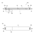
- FIG. 2 is a perspective view showing a merging block 14 in which the gas unit 22 constituting the concentration measuring device 20 of the first embodiment is formed, and FIGS. 3A and 3B are provided in the merging block 14. It is a vertical sectional view and a side view which show the gas unit 22.
- the merging block 14 used in the present embodiment is fixed on a base plate 16 provided with an integration unit, and is provided with an elongated through hole extending along the longitudinal direction D1 of the merging block 14. It has a main flow path L1 to be formed. Further, a plurality of sub flow paths L2 are connected to the main flow path L1. Each of the sub flow paths L2 is formed by holes provided so as to reach the main flow path from the upper surface of the merging block 14, and extends in a direction intersecting with the main flow path L1 (here, a direction orthogonal to each other). ..
- the through holes and holes forming the main flow path L1 and the sub flow path L2 can be easily formed in the merging block 14 by drilling with a drill.
- the merging block 14 may be made of, for example, stainless steel (particularly SUS316L), like the other flow path blocks constituting the integration unit.
- each supply line provided in the integration unit (more specifically, an on-off valve provided in the final stage of each line). Exit) is connected.
- the gas GasA, GasB, and GasC flowing through the arbitrary supply line of the integration unit can be flowed to the main flow path L1 via the sub flow path L2 of the merging block 14.
- a triple block in which three supply lines are connected is used as the merging block 14, but the present invention is not limited to this, and an arbitrary number of gas supply lines are connected. Blocks can be used.
- an outlet block 14A in which an L-shaped outflow path L3 communicating with the main flow path L1 is formed is fixed to the merging block 14.
- the merging block 14 is formed with a flow path for connecting the outflow path L3 of the outlet block 14A and the main flow path L1.
- the outlet block 14A is firmly fixed to the merging block 14 via a gasket by screwing, and gas can flow out from the main flow path L1 through the outflow path L3.
- the opening of the outflow passage L3 formed on the upper surface of the outlet block 14A is connected to an on-off valve (shutoff valve) (not shown).
- shutoff valve an on-off valve
- the gas flow from the integration unit can be stopped more reliably.
- the outflow path of the shutoff valve is connected to a flow path block provided with a tubular joint serving as a gas outlet, and when the shutoff valve is open, gas is sent to the downstream flow path and the process chamber via the tubular joint. Is supplied.
- FIGS. 4A and 4B show the merging block 14 of another aspect.
- the merging block 14 shown in FIGS. 4A and 4B has a joint portion 14b on the side surface and is provided with an L-shaped outflow path L3 that communicates the joint portion 14b and the upper surface opening. It is configured using.
- the outflow path L3 of the exit block 14B is different from the outflow path L3 of the exit block 14A shown in FIG. 2 and does not directly communicate with the main flow path L1.
- the upper surface opening of the outlet sub-flow path L2'(one of the sub-flow paths) and the upper surface opening of the exit block 14B straddle both. It is connected to a shutoff valve 18 arranged so as to.
- the outlet sub-flow path L2'communicating with the main flow path L1 is used to flow the gas from the main flow path L1 to the outflow path L3 of the outlet block 14B via the shutoff valve 18. Then, gas can be supplied to the process chamber from the side joint portion 14b of the outlet block 14B via the flow path.
- various merging blocks 14 can be used, but an example of forming the gas unit 22 by using the merging block 14 shown in FIG. 2 will be described below. However, it goes without saying that the gas unit 22 can be formed in the merging block 14 of another aspect as in the embodiment described below.
- FIG. 3 (a) and 3 (b) show the configuration of the gas unit 22 of the concentration measuring device 20 of the present embodiment.
- the gas unit 22 has a translucent incident window 26 and a translucent exit window 28 arranged at the end of the main flow path L1 of the merging block 14. ..
- the entrance window 26 and the exit window 28 are sealed and fixed to both ends of the merging block 14 by using sealing members 27 and 29.
- the main flow path L1 seals both ends of the through holes formed so as to extend along the longitudinal direction of the merging block 14 with sealing members 27 and 29 (here, blind joints), respectively. It is formed by doing. Then, using this sealing member, the optical system of the gas unit 22 constituting the concentration measuring device 20 is arranged.
- a collimator is provided on the sealing member 27 (hereinafter, may be referred to as a first sealing member) for fixing the incident window 26. Further, a condenser lens is provided on the sealing member 29 (hereinafter, may be referred to as a second sealing member) for fixing the exit window 28.
- the incident window 26 and the exit window 28 are arranged so as to face each other with the main flow path L1 interposed therebetween, and light incident from the incident window 26 and traveling straight through the main flow path L1 can be emitted from the exit window 28. it can.
- the main flow path L1 of the merging block 14 is used as an optical path for measurement light.
- the first sealing member 27 for fixing the incident window 26 is provided with an optical transmission line member connected to a collimator, specifically, an optical fiber 30.
- the optical fiber 30 is used for transmitting measurement light (here, ultraviolet light) from the electric unit 24 to the gas unit 22.
- the transmitted light is converted into parallel light by a collimator and then incident on the main flow path L1 through the incident window 26.
- the second sealing member 29 that fixes the exit window 28 is provided with an optical fiber 31 that receives the light collected by the condenser lens.
- the optical fiber 31 is used to transmit the light that has passed through the main flow path L1 of the gas unit 22 to the electric unit 24.
- the light includes not only visible light but also at least infrared rays and ultraviolet rays, and may include electromagnetic waves of any wavelength.
- the translucency means that the internal transmittance with respect to the light incident on the main flow path L1 is sufficiently high so that the concentration can be measured.
- the entrance window 26 and the exit window 28 are formed of, for example, a circular sapphire plate having a thickness of 0.5 mm to 2 mm and a diameter of 5 mm to 30 mm.
- sapphire which has resistance to detection light used for density measurement of ultraviolet light and the like and has high transmittance and is mechanically and chemically stable, is preferably used, but other Stable materials such as quartz glass can also be used.
- a metal gasket (for example, made of SUS316L) may be arranged.
- the metal gasket may be provided with an annular convex portion that is crushed to improve the sealing property.
- a diameter-expanded portion at the end of the main flow path L1 may be formed at the attachment portion of the incident window 26 and the exit window 28 in the merging block 14, and the diameter-expanded portion of the enlarged portion may be formed.
- the support surface of the enlarged diameter portion may be formed with a recess for fitting having a shape suitable for the incident window 26 and the exit window 28.
- the metal gasket with the annular convex portion may be arranged between the support surface of the enlarged diameter portion and the incident window 26 and the exit window 28 to improve the sealing property and maintainability.
- the blind joint used as the first and second sealing members 27 and 29 may be, for example, a metal plug having a male screw coated with a sealing material on the peripheral surface, and these are formed at both ends of the merging block 14.
- the incident window 26 and the exit window 28 can be sealed and fixed while being pressed against the support surface.
- the first and second sealing members 27 and 29 may be of any embodiment as long as the incident window 26 and the exit window 28 can be fixed while appropriately sealing the main flow path L1. For example, it may be fixed by caulking.
- the gas unit 22 configured as described above can receive incident light from the electric units 24 provided apart from each other and send the light after passing through the main flow path L1 to the electric unit 24. Since the gas unit 22 is formed by using the merging block 14 of the integrated unit, it can be compactly incorporated into the gas supply system with a relatively simple configuration, and the installation space of the gas unit, which has been conventionally required, can be reduced. Can be done. Further, as the electric unit 24, a conventionally used unit can be used, and cost reduction can be realized.
- FIG. 5 shows the configuration of the electric unit 24 used in this embodiment.
- the electric unit 24 includes a light source 40 that emits light for incident on the merging block 14 (see FIG. 3), a photodetector 44 that receives the light emitted from the merging block 14, and a photodetector. It is provided with an arithmetic control circuit 46 that calculates the gas concentration based on the detection signal output by 44 (detection signal according to the intensity of received light). Further, the electric unit 24 is also provided with a reference photodetector 48 that receives the reference light from the light source 40. In this embodiment, the electric unit 24 is optically connected to the gas unit 22 by optical fibers 30 and 31.
- the light source 40 includes two light emitting elements (here, LEDs) 41 and 42 that emit ultraviolet light having different wavelengths from each other. Drive currents of different frequencies are passed through the light emitting elements 41 and 42 using an oscillation circuit, and frequency analysis (for example, fast Fourier transform or wavelet transform) is performed to obtain the detection signal detected by the photodetector 44. The intensity of light corresponding to each frequency component can be measured.
- LEDs light emitting elements
- frequency analysis for example, fast Fourier transform or wavelet transform
- light emitting elements 41 and 42 light emitting elements other than LEDs, for example, LD (laser diode) can also be used. Further, instead of using a plurality of combined wave lights having different wavelengths as a light source, a single wavelength light source can be used. In this case, the combiner and the frequency analysis circuit can be omitted. Three or more light emitting elements may be provided, or may be configured to generate incident light using only an arbitrary light emitting element selected from the provided light emitting elements. A resistance temperature detector may be attached to the light source 40. Further, the light emitted by the light emitting element is not limited to ultraviolet light, but may be visible light or infrared light.
- the wavelength of light may be appropriately selected based on the absorption characteristics of the gas to be measured, but in the present embodiment, an organometallic gas that absorbs ultraviolet light (for example, trimethylgallium (TMGa) or trimethylaluminum (TMAl)) ) Is measured using ultraviolet light.
- an organometallic gas that absorbs ultraviolet light for example, trimethylgallium (TMGa) or trimethylaluminum (TMAl)
- the light source 40 and the reference photodetector 48 are attached to the beam splitter 49.
- the beam splitter 49 functions to incident a part of the light from the light source 40 onto the reference photodetector 48 and to guide the remaining light to the gas unit 22 via the optical fiber 30.
- a photodiode or a phototransistor is preferably used as the light receiving element constituting the photodetector 44 and the reference photodetector 48.
- the arithmetic control circuit 46 is composed of, for example, a processor or memory provided on a circuit board, includes a computer program that executes a predetermined arithmetic based on an input signal, and can be realized by a combination of hardware and software. .. In the illustrated embodiment, the arithmetic control circuit 46 is built in the electric unit 24, but a part (CPU or the like) or all of its constituent elements may be provided outside the electric unit 24.
- I 0 is the intensity of the incident light incident on the main flow path L1
- I is the intensity of the light passing through the gas in the main flow path L1
- ⁇ ' is the molar extinction coefficient (m 2 /).
- mol) is the optical path length of the main flow passage L1 (m)
- C M is the molar concentration (mol / m 3).
- the molar extinction coefficient ⁇ ' is a coefficient determined by the substance.
- I / I 0 is generally called transmittance. When the transmittance I / I 0 is 100%, the absorbance A ⁇ becomes 0, and when the transmittance I / I 0 is 0%, the absorbance A ⁇ is infinite. It becomes.
- the intensity of light detected by the photodetector 44 may be regarded as the incident light intensity I 0 .
- the optical path length L of the main flow path L1 is a distance from the surface of the incident window 26 on the gas contact side to the surface of the exit window 28 on the gas contact side, and this distance is known in advance. There is.
- the concentration measuring device 20 of the present embodiment can determine the concentration of the gas based on the absorbance of the light passing through the main flow path L1.
- the concentration measuring device 20 may be configured to obtain the gas concentration in consideration of the pressure and temperature of the gas flowing through the main flow path L1 of the merging block 14.
- an aspect of obtaining the concentration of the measurement gas (that is, the gas to be measured) contained in the mixed gas in consideration of the pressure and the temperature will be described.
- C M n / V.
- n is the amount of substance (mol) of the gas, that is, the number of moles
- V is the volume (m 3 ).
- P the pressure (Torr)
- T the temperature (K).
- the pressure that can be detected by the pressure sensor is the total pressure Pt (Torr) of the mixed gas containing the measurement gas and the carrier gas.
- the measured gas concentration (volume%) at the measured light wavelength can be obtained by calculation based on each measured value (gas temperature T, total pressure Pt, and transmitted light intensity I). Is.
- concentration of the absorbed gas in the mixed gas can be obtained in consideration of the gas temperature and the gas pressure.
- the extinction coefficient ⁇ a can be obtained in advance according to the formula (3) or (4) from the measured values (T, Pt, I) when a measurement gas having a known concentration (for example, 100% concentration) is flowed. it can.
- the extinction coefficient ⁇ a obtained in this way is stored in the memory, and when calculating the concentration of the measurement gas having an unknown concentration based on the equation (4), the extinction coefficient ⁇ a is read from the memory and used. Can be done.
- the temperature sensor for measuring the gas temperature T flowing through the main flow path L1 may be separately attached to the merging block 14, or the flow control device 12 provided in the integration unit has the temperature sensor. In some cases, the output of this temperature sensor may be used as the gas temperature T. Further, the pressure sensor for measuring the total pressure Pt may be separately attached to the merging block 14, or if the flow control device 12 has a pressure sensor on the downstream side, this pressure sensor may be attached. It is also possible to measure the total pressure Pt using.
- (Embodiment 2) 6 (a) and 6 (b) are a vertical sectional view and a side view showing a gas unit 22a included in the concentration measuring device of the second embodiment. Also in this embodiment, the gas unit 22a is configured by using the merging block 14 (see FIGS. 2 and 4) fixed to the integration unit.
- the same components as those in the first embodiment may be designated by the same reference numerals and detailed description thereof may be omitted.
- the gas unit 22a of the present embodiment is provided with a sealing member 27a with a built-in LED that is also used as a light source and a sealing member 29a with a built-in photodiode that is also used as a photodetector at both ends of the merging block 14.
- a sealing member 27a is used for sealing and fixing the incident window 26
- the sealing member 29a is used for sealing and fixing the exit window 28.
- the gas unit 22a of the present embodiment is configured to include the light source and the photodetector, it is not necessary to provide the light source and the photodetector in the electric unit connected to the gas unit 22a. ..
- the electric unit may include the same arithmetic control circuit 46 as in the first embodiment.
- the gas unit 22a receives a signal for controlling the light emission of the LED built in the sealing member 27a from the arithmetic control circuit provided in the electric unit via the wiring cable 32, and is incident.
- the measurement light is incident on the main flow path L1 through the window 26. Further, the light that has passed through the main flow path L1 is received by the photodiode of the sealing member 29a through the exit window 28. Then, it is converted into an electric signal by a photodiode and sent to the arithmetic control circuit of the electric unit via the wiring cable 33.
- the arithmetic control circuit can calculate the concentration of the gas flowing through the main flow path L1 based on the received electric signal, as in the first embodiment.
- the concentration measuring device of the second embodiment configured as described above can also be compactly incorporated into the gas supply system with a relatively simple configuration, and the installation space of the gas unit, which has been conventionally required, can be reduced.
- FIGS. 2 and 4 are a vertical sectional view and a side view showing a gas unit 22b included in the concentration measuring device of the third embodiment. Also in this embodiment, the gas unit 22b is configured by using the merging block 14 (see FIGS. 2 and 4) fixed to the integration unit.
- the same components as those in the first embodiment may be designated by the same reference numerals and detailed description thereof may be omitted.
- a common window member 23 that also serves as an incident window and an exit window is sealed and fixed to one end of the merging block 14 by a sealing member 27b.
- a reflective member 25 is sealed and fixed to the other end of the merging block 14 by a sealing member 29b.
- the reflecting surface of the reflecting member 25 is provided perpendicular to the traveling direction of the incident light or the central axis of the flow path, and the light traveling straight through the main flow path L1 can be reflected in the same direction.
- the reflective member 25 may be, for example, an aluminum layer as a reflective layer formed on the back surface of a sapphire plate (emission window 28 of embodiments 1 and 2) by sputtering. Further, the reflective member 25 may include a dielectric multilayer film as the reflecting layer, and if the dielectric multilayer film is used, light in a specific wavelength range (for example, near-ultraviolet rays) can be selectively reflected. ..
- the dielectric multilayer film is composed of a laminate of a plurality of optical coatings having different refractive indexes (a laminate of a high refractive index thin film and a low refractive index thin film), and the thickness and refractive index of each layer are appropriately selected. This makes it possible to reflect or transmit light of a specific wavelength.
- the dielectric multilayer film can reflect light at an arbitrary ratio, for example, when the incident light is reflected by the reflecting member 25, the incident light is not reflected 100% but is partially (for example). (For example, 10%) is transmitted, and the transmitted light can be received by a light detector or the like installed outside the reflecting member 25, and the transmitted light can be used as reference light.
- the gas unit 22b of the present embodiment is optically connected to the same electric unit 24 as that of the first embodiment. However, since light is incident and emitted at one end of the merging block 14, both the optical fiber 30 for incident and the optical fiber 31 for exit are connected to the sealing member 27b. ..
- the light from the light source 40 provided in the electric unit 24 is guided by the optical fiber 30 to the common window member 23 of the main flow path L1, and is guided from the common window member 23 to the main flow path. It is incident on L1. Further, the light that has passed through the main flow path L1 and is reflected by the reflecting member 25 is emitted from the common window member 23 and guided by the optical fiber 31 to the photodetector 44 of the electric unit.
- the influence of stray light is reduced by separately providing the optical fiber 30 for guiding the light to the main flow path L1 and the optical fiber 31 for guiding the light emitted from the main flow path L1.
- a single optical transmission line member for both incident light and emitted light such as an optical fiber bundle, is used to connect the light source and the photodetector to the measurement cell. May be good.
- Patent Document 2 The configuration of the reflection type concentration measuring device is described in, for example, Patent Document 2.
- various aspects described in Patent Document 2 can be applied to the design of the optical system.
- the concentration measuring device of the third embodiment configured as described above can also be compactly incorporated into the gas supply system with a relatively simple configuration, and the installation space of the gas unit, which has been conventionally required, can be reduced.
- the optical path length L of the main flow path L1 is defined as twice the distance from the surface of the incident window 26 on the gas contact side to the surface of the reflection member 25 on the gas contact side. Therefore, it is possible to obtain twice the optical path length with the same dimensions. As a result, the measurement accuracy can be improved in spite of the miniaturization. Further, in the concentration measuring device of the third embodiment, since light is incident and emitted only on one side of the merging block 14, the number of parts can be reduced.
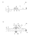
- (Embodiment 4) 8 (a) and 8 (b) are a top view and a side sectional view showing the gas unit 22c included in the concentration measuring device of the fourth embodiment.
- the gas unit 22c of the present embodiment is also configured by using the merging block 14 fixed to the integrated unit.
- the same components as those in the third embodiment may be designated by the same reference numerals and detailed description thereof may be omitted.
- the gas unit 22c of the present embodiment is configured to inject light in the same direction as the sub-flow path L2 instead of the main flow path L1 and measure the intensity of the transmitted light.
- the gas unit 22c utilizes one of the sub-channels L2 for arranging the optical system, and the optical system for density measurement is arranged on the upper surface of the merging block 14. Further, the gas unit 22c constitutes a reflection type concentration measuring device as in the third embodiment.
- the sub-channel L2 in which the optical system is arranged may be referred to as a measurement hole portion in order to distinguish it from the sub-channel L2 connected to the gas supply line.
- the measurement hole portion is typically a hole extending in a direction parallel to the sub flow path L2.
- the gas unit 22c has a collimator 50 provided on the upper surface of the merging block 14 and a window holding member 52 for sealing and fixing the common window member 23, and the collimator 50 and the window holding member 52 are sealed. It functions as a stop member 27b.
- the collimator 50 is provided with a collimator lens 50a, and after the light from the optical fiber 30 is made into parallel light, the light can be incident on the measurement hole along the sub-channel L2 direction through the common window member 23. it can.
- the collimator 50 and the window holding member 52 can be fixed to the merging block 14 by inserting bolts into the bolt holes 55.
- a reflective member 25 is provided so as to face the common window member 23.
- the reflective member 25 is sealed and fixed by the sealing member 29b.
- the light reflected by the reflecting member 25 returns to the measurement hole portion, passes through the common window member 23, and is input to the collimator 50. Then, it is transmitted to the photodetector of the electric unit via the optical fiber 31.
- the gas concentration can be calculated by calculation based on the output of the photodetector.
- the optical path length L in this embodiment is obtained as twice the distance between the common window member 23 and the reflective member 25 in the vertical direction.
- the main flow path L1 is not used as an optical path, it is not necessary to arrange optical systems at both ends of the main flow path L1. Therefore, as shown in FIGS. 8A and 8B, the main flow path L1 is not a through hole, but an elongated hole extending to the innermost sub flow path L2 is sealed by a sealing member 54. Is formed by. Further, in another aspect, a joint member may be provided instead of the sealing member 54, and this may be used as a gas outlet to allow gas to flow to the downstream side.
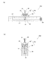
- the gas unit 22d constitutes a reflection type concentration measuring device that reciprocates light along the direction of the sub-channel L2, as in the fourth embodiment. ..
- the support member 58 connected to the sealing member 27b of the common window member 23 provided on the upper surface of the merging block 14 Is used to support the reflective member 25.
- the sealing member 27b is composed of a collimator 50 and a window receiving member 56.
- the support member 58 extends from the window receiving member 56 and can be inserted from above along the measurement hole portion with the reflection member 25 attached.
- the reflecting member 25 can be arranged below the flow path from above the merging block 14 by using one of the sub-flow paths L2 without particularly processing the merging block 14. it can.
- the reflective member 25 in addition to the collimator 50 and the common window member 23, the reflective member 25 can also be integrated, which is highly convenient.
- the support member 58 has a length that reaches the main flow path L1 in order to perform good gas concentration measurement.
- the support member 58 is not limited to a plate-like member as shown in the drawing, and may be cylindrical and has one side surface cut, or may be composed of two rods.
- the support member 58 may have any embodiment as long as it does not cross the optical path of the measurement light and does not prevent the gas from reaching the optical path.
- concentration measuring devices according to the first to fifth embodiments have been described above, but each of the concentration measuring devices is compactly incorporated into the gas supply system using the merging block, and the concentration of various gases flowing through the merging block is appropriately adjusted. Can be measured.
- the present invention is not limited to the above embodiment, and various modifications can be made without departing from the spirit of the present invention.
- the concentration measuring device is incorporated in a gas supply system and is suitably used for measuring the concentration of gas.
- Gas supply system 3 Gas supply source 5 Supply line 7 Process chamber 9 Vacuum pump 10 Integration unit 12 Flow control device 14 Confluence block 16 Base plate 20 Concentration measuring device 22 Gas unit 23 Common window member 24 Electric unit 25 Reflective member 26 Incident window 27 Sealing member 28 Exit window 29 Sealing member 30, 31 Optical fiber 32, 33 Wiring cable 40 Light source 44 Optical detector 46 Arithmetic control circuit 48 Reference optical detector
Landscapes
- Physics & Mathematics (AREA)
- Spectroscopy & Molecular Physics (AREA)
- Health & Medical Sciences (AREA)
- Life Sciences & Earth Sciences (AREA)
- Chemical & Material Sciences (AREA)
- Analytical Chemistry (AREA)
- Biochemistry (AREA)
- General Health & Medical Sciences (AREA)
- General Physics & Mathematics (AREA)
- Immunology (AREA)
- Pathology (AREA)
- Engineering & Computer Science (AREA)
- Mathematical Physics (AREA)
- Theoretical Computer Science (AREA)
- Investigating Or Analysing Materials By Optical Means (AREA)
- Optical Measuring Cells (AREA)
Abstract
Description
図2は、実施形態1の濃度測定装置20を構成するガスユニット22が形成される合流ブロック14を示す斜視図であり、図3(a)および(b)は、合流ブロック14に設けられたガスユニット22を示す縦断面図および側面図である。
Aλ=-log10(I/I0)=α’LCM ・・・(1)
ln(I0/I)=αL(P/RT) ・・・(2)
ln(I0/I)=αaL(Pt・Cv/RT) ・・・(3)
Cv=(RT/αaLPt)・ln(I0/I) ・・・(4)
図6(a)および(b)は、実施形態2の濃度測定装置が備えるガスユニット22aを示す縦断面図および側面図である。本実施形態においても、ガスユニット22aは、集積化ユニットに固定された合流ブロック14(図2、図4参照)を利用して構成されている。以下、実施形態1と同様の構成要素については、同じ参照符号を付すとともに詳細な説明を省略することがある。
図7(a)および(b)は、実施形態3の濃度測定装置が備えるガスユニット22bを示す縦断面図および側面図である。本実施形態においても、ガスユニット22bは、集積化ユニットに固定された合流ブロック14(図2、図4参照)を利用して構成されている。以下、実施形態1と同様の構成要素については、同じ参照符号を付すとともに詳細な説明を省略することがある。
図8(a)および(b)は、実施形態4の濃度測定装置が備えるガスユニット22cを示す上面図および側方からの横断面図である。本実施形態のガスユニット22cも、集積化ユニットに固定された合流ブロック14を利用して構成されている。以下、実施形態3と同様の構成要素については、同じ参照符号を付すとともに詳細な説明を省略することがある。
図9(a)および(b)は、実施形態5の濃度測定装置が備えるガスユニット22dを示す側方からの横断面図および端面からの横断面図である。本実施形態のガスユニット22dも、集積化ユニットに固定された合流ブロック14を利用して構成されている。以下、実施形態3、4と同様の構成要素については、同じ参照符号を付すとともに詳細な説明を省略することがある。
3 ガス供給源
5 供給ライン
7 プロセスチャンバ
9 真空ポンプ
10 集積化ユニット
12 流量制御装置
14 合流ブロック
16 ベースプレート
20 濃度測定装置
22 ガスユニット
23 共通窓部材
24 電気ユニット
25 反射部材
26 入射窓
27 封止部材
28 出射窓
29 封止部材
30、31 光ファイバ
32、33 配線ケーブル
40 光源
44 光検出器
46 演算制御回路
48 参照光検出器
Claims (10)
- 複数のガス供給ラインが接続された合流ブロックを流れるガスの濃度を測定するように構成された濃度測定装置であって、
前記合流ブロックに形成された流路に入射させる光を発する光源と、
前記流路から出射した光を受け取る光検出器と、
前記光検出器の出力に基づいて前記流路を流れるガスの濃度を求める演算制御回路と
を備え、
前記合流ブロックに対して、前記光源からの光を前記流路に入射させるための透光性の入射窓および前記流路を通過した光を出射させるための透光性の出射窓の少なくともいずれかが封止固定されている、濃度測定装置。 - 前記合流ブロックは、前記複数のガス供給ラインがそれぞれ接続される複数のサブ流路と、前記複数のサブ流路が接続されるメイン流路とを有し、
前記入射窓と前記出射窓とが、前記メイン流路の両端部に封止固定されている、請求項1に記載の濃度測定装置。 - 前記入射窓は、前記合流ブロックに対して、コリメータを有する第1封止部材によって封止固定され、前記光源と前記第1封止部材とが光伝送路部材によって繋がれており、
前記出射窓は、前記合流ブロックに対して、第2封止部材によって封止固定され、前記光検出器と前記第2封止部材とは光伝送路部材によって繋がれている、請求項2に記載の濃度測定装置。 - 前記入射窓は、前記合流ブロックに対して、前記光源およびコリメータを有する第1封止部材によって封止固定され、
前記出射窓は、前記合流ブロックに対して、前記光検出器を有する第2封止部材によって封止固定されている、請求項2に記載の濃度測定装置。 - 前記合流ブロックは、前記複数のガス供給ラインがそれぞれ接続される複数のサブ流路と、前記複数のサブ流路が接続されるメイン流路とを有し、
前記入射窓は、前記出射窓を兼ねる共通窓部材であり、前記共通窓部材が前記メイン流路の一端部に封止固定され、前記流路に入射した光を反射する反射部材が前記メイン流路に固定されている、請求項1に記載の濃度測定装置。 - 前記共通窓部材と前記光源とを接続するための光伝送路部材と、前記共通窓部材と前記光検出器とを接続するための光伝送路部材とが、別個に設けられている、請求項5に記載の濃度測定装置。
- 前記合流ブロックは、前記複数のガス供給ラインがそれぞれ接続される複数のサブ流路と、前記複数のサブ流路が接続されるメイン流路とを有し、
前記入射窓は、前記出射窓を兼ねる共通窓部材であり、前記共通窓部材が、測定用穴部を封止するように固定されており、前記測定用穴部に入射した光を反射する反射部材が前記共通窓部材と対向するように配置されている、請求項1に記載の濃度測定装置。 - 前記共通窓部材を封止固定するための封止部材と接続され、前記測定用穴部に沿って延びる支持部材を有し、前記反射部材が前記支持部材によって支持されている、請求項7に記載の濃度測定装置。
- 前記メイン流路は、前記合流ブロックの長手方向に沿って延びる貫通孔によって形成されており、前記複数のサブ流路の各々は、前記メイン流路と交差する方向に延び、前記合流ブロックの表面から前記メイン流路に達するように設けられた穴によって形成されている、請求項2から8のいずれかに記載の濃度測定装置。
- 前記合流ブロックは、前記複数のガス供給ラインがベースプレート上に形成された集積化ユニットの出口側において前記ベースプレート上に固定された流路ブロックである、請求項1から9のいずれかに記載の濃度測定装置。
Priority Applications (4)
| Application Number | Priority Date | Filing Date | Title |
|---|---|---|---|
| CN202080018145.8A CN113508287A (zh) | 2019-03-29 | 2020-03-18 | 浓度测定装置 |
| KR1020217019233A KR102525333B1 (ko) | 2019-03-29 | 2020-03-18 | 농도 측정 장치 |
| US17/442,529 US12424468B2 (en) | 2019-03-29 | 2020-03-18 | Concentration measurement device |
| JP2021511410A JP7699819B2 (ja) | 2019-03-29 | 2020-03-18 | 濃度測定装置 |
Applications Claiming Priority (2)
| Application Number | Priority Date | Filing Date | Title |
|---|---|---|---|
| JP2019-065571 | 2019-03-29 | ||
| JP2019065571 | 2019-03-29 |
Publications (1)
| Publication Number | Publication Date |
|---|---|
| WO2020203281A1 true WO2020203281A1 (ja) | 2020-10-08 |
Family
ID=72668744
Family Applications (1)
| Application Number | Title | Priority Date | Filing Date |
|---|---|---|---|
| PCT/JP2020/011902 Ceased WO2020203281A1 (ja) | 2019-03-29 | 2020-03-18 | 濃度測定装置 |
Country Status (6)
| Country | Link |
|---|---|
| US (1) | US12424468B2 (ja) |
| JP (1) | JP7699819B2 (ja) |
| KR (1) | KR102525333B1 (ja) |
| CN (1) | CN113508287A (ja) |
| TW (1) | TWI756651B (ja) |
| WO (1) | WO2020203281A1 (ja) |
Families Citing this family (3)
| Publication number | Priority date | Publication date | Assignee | Title |
|---|---|---|---|---|
| JP7393753B2 (ja) * | 2021-07-31 | 2023-12-07 | 株式会社フジキン | 濃度測定装置 |
| TWI817195B (zh) * | 2021-09-07 | 2023-10-01 | 劉茂誠 | 混濁液體光學偵測的系統與方法 |
| CN121666529A (zh) * | 2023-08-24 | 2026-03-13 | 三菱电机株式会社 | 臭氧浓度测定装置、臭氧浓度测定方法以及臭氧产生系统 |
Citations (8)
| Publication number | Priority date | Publication date | Assignee | Title |
|---|---|---|---|---|
| JPH05132393A (ja) * | 1991-11-08 | 1993-05-28 | Mitsubishi Electric Corp | 化学気相成長装置 |
| JPH08153685A (ja) * | 1994-11-25 | 1996-06-11 | Mitsubishi Corp | 半導体用特殊材料ガス供給装置 |
| WO2008074142A1 (en) * | 2006-12-18 | 2008-06-26 | Picomole Instruments Inc. | Apparatus and method for rapid and accurate quantification of an unknown, complex mixture |
| JP2011196832A (ja) * | 2010-03-19 | 2011-10-06 | Fuji Electric Co Ltd | レーザ式ガス分析装置 |
| JP2012173022A (ja) * | 2011-02-18 | 2012-09-10 | Shimadzu Corp | ガスセル |
| WO2017029792A1 (ja) * | 2015-08-18 | 2017-02-23 | 国立大学法人徳島大学 | 濃度測定装置 |
| JP2017211357A (ja) * | 2015-12-03 | 2017-11-30 | 富士電機株式会社 | レーザ式ガス分析装置 |
| JP2018017644A (ja) * | 2016-07-29 | 2018-02-01 | 国立大学法人徳島大学 | 濃度測定装置 |
Family Cites Families (10)
| Publication number | Priority date | Publication date | Assignee | Title |
|---|---|---|---|---|
| JP2002031621A (ja) | 2000-07-14 | 2002-01-31 | Ngk Spark Plug Co Ltd | ガス濃度センサ |
| JP2002089798A (ja) | 2000-09-11 | 2002-03-27 | Ulvac Japan Ltd | 流体制御装置およびこれを用いたガス処理装置 |
| JP2003207448A (ja) | 2002-01-09 | 2003-07-25 | Horiba Ltd | ガス分析装置 |
| JP3973605B2 (ja) | 2002-07-10 | 2007-09-12 | 東京エレクトロン株式会社 | 成膜装置及びこれに使用する原料供給装置、成膜方法 |
| JP5202101B2 (ja) | 2008-05-21 | 2013-06-05 | 旭有機材工業株式会社 | ミキシングバルブ及びそれを用いたミキシング装置 |
| US20120330568A1 (en) * | 2010-02-16 | 2012-12-27 | Hamamatsu Photonics K.K. | Gas concentration calculation device, gas concentration measurement module, and light detector |
| KR101366019B1 (ko) | 2010-02-22 | 2014-02-21 | 가부시키가이샤 후지킨 | 혼합 가스 공급 장치 |
| EP2632593B1 (en) * | 2010-10-27 | 2021-09-29 | Illumina, Inc. | Flow cells for biological or chemical analysis |
| JP6012247B2 (ja) | 2012-04-27 | 2016-10-25 | 株式会社フジキン | 流体制御装置 |
| JP5478666B2 (ja) | 2012-05-21 | 2014-04-23 | 株式会社アルバック | 流体制御装置およびこれを用いたガス処理装置 |
-
2020
- 2020-03-18 US US17/442,529 patent/US12424468B2/en active Active
- 2020-03-18 JP JP2021511410A patent/JP7699819B2/ja active Active
- 2020-03-18 KR KR1020217019233A patent/KR102525333B1/ko active Active
- 2020-03-18 WO PCT/JP2020/011902 patent/WO2020203281A1/ja not_active Ceased
- 2020-03-18 CN CN202080018145.8A patent/CN113508287A/zh active Pending
- 2020-03-24 TW TW109109775A patent/TWI756651B/zh active
Patent Citations (8)
| Publication number | Priority date | Publication date | Assignee | Title |
|---|---|---|---|---|
| JPH05132393A (ja) * | 1991-11-08 | 1993-05-28 | Mitsubishi Electric Corp | 化学気相成長装置 |
| JPH08153685A (ja) * | 1994-11-25 | 1996-06-11 | Mitsubishi Corp | 半導体用特殊材料ガス供給装置 |
| WO2008074142A1 (en) * | 2006-12-18 | 2008-06-26 | Picomole Instruments Inc. | Apparatus and method for rapid and accurate quantification of an unknown, complex mixture |
| JP2011196832A (ja) * | 2010-03-19 | 2011-10-06 | Fuji Electric Co Ltd | レーザ式ガス分析装置 |
| JP2012173022A (ja) * | 2011-02-18 | 2012-09-10 | Shimadzu Corp | ガスセル |
| WO2017029792A1 (ja) * | 2015-08-18 | 2017-02-23 | 国立大学法人徳島大学 | 濃度測定装置 |
| JP2017211357A (ja) * | 2015-12-03 | 2017-11-30 | 富士電機株式会社 | レーザ式ガス分析装置 |
| JP2018017644A (ja) * | 2016-07-29 | 2018-02-01 | 国立大学法人徳島大学 | 濃度測定装置 |
Also Published As
| Publication number | Publication date |
|---|---|
| JP7699819B2 (ja) | 2025-06-30 |
| US20220172969A1 (en) | 2022-06-02 |
| TWI756651B (zh) | 2022-03-01 |
| KR20210091313A (ko) | 2021-07-21 |
| KR102525333B1 (ko) | 2023-04-25 |
| US12424468B2 (en) | 2025-09-23 |
| CN113508287A (zh) | 2021-10-15 |
| JPWO2020203281A1 (ja) | 2020-10-08 |
| TW202100982A (zh) | 2021-01-01 |
Similar Documents
| Publication | Publication Date | Title |
|---|---|---|
| US11630058B2 (en) | Concentration measurement device | |
| KR20180104090A (ko) | 농도 측정 장치 | |
| KR102733863B1 (ko) | 농도 측정 방법 및 농도 측정 장치 | |
| JP7699819B2 (ja) | 濃度測定装置 | |
| KR102593815B1 (ko) | 농도 측정 장치 | |
| JP7492269B2 (ja) | 濃度測定装置 | |
| US11686671B2 (en) | Concentration measurement device | |
| JP2021021714A (ja) | 異常検知方法 | |
| JP7244900B2 (ja) | 反射部材の表裏識別方法 |
Legal Events
| Date | Code | Title | Description |
|---|---|---|---|
| 121 | Ep: the epo has been informed by wipo that ep was designated in this application |
Ref document number: 20783261 Country of ref document: EP Kind code of ref document: A1 |
|
| ENP | Entry into the national phase |
Ref document number: 2021511410 Country of ref document: JP Kind code of ref document: A |
|
| ENP | Entry into the national phase |
Ref document number: 20217019233 Country of ref document: KR Kind code of ref document: A |
|
| NENP | Non-entry into the national phase |
Ref country code: DE |
|
| 122 | Ep: pct application non-entry in european phase |
Ref document number: 20783261 Country of ref document: EP Kind code of ref document: A1 |
|
| WWG | Wipo information: grant in national office |
Ref document number: 17442529 Country of ref document: US |