WO2020202449A1 - モニタリングシステム、モニタリング方法、およびプログラム - Google Patents
モニタリングシステム、モニタリング方法、およびプログラム Download PDFInfo
- Publication number
- WO2020202449A1 WO2020202449A1 PCT/JP2019/014550 JP2019014550W WO2020202449A1 WO 2020202449 A1 WO2020202449 A1 WO 2020202449A1 JP 2019014550 W JP2019014550 W JP 2019014550W WO 2020202449 A1 WO2020202449 A1 WO 2020202449A1
- Authority
- WO
- WIPO (PCT)
- Prior art keywords
- living area
- information
- terminal
- position information
- monitoring system
- Prior art date
- Legal status (The legal status is an assumption and is not a legal conclusion. Google has not performed a legal analysis and makes no representation as to the accuracy of the status listed.)
- Ceased
Links
Images


Classifications
-
- G—PHYSICS
- G08—SIGNALLING
- G08B—SIGNALLING OR CALLING SYSTEMS; ORDER TELEGRAPHS; ALARM SYSTEMS
- G08B21/00—Alarms responsive to a single specified undesired or abnormal condition and not otherwise provided for
- G08B21/02—Alarms for ensuring the safety of persons
- G08B21/0202—Child monitoring systems using a transmitter-receiver system carried by the parent and the child
- G08B21/0294—Display details on parent unit
-
- H—ELECTRICITY
- H04—ELECTRIC COMMUNICATION TECHNIQUE
- H04W—WIRELESS COMMUNICATION NETWORKS
- H04W4/00—Services specially adapted for wireless communication networks; Facilities therefor
- H04W4/02—Services making use of location information
- H04W4/029—Location-based management or tracking services
-
- G—PHYSICS
- G06—COMPUTING OR CALCULATING; COUNTING
- G06Q—INFORMATION AND COMMUNICATION TECHNOLOGY [ICT] SPECIALLY ADAPTED FOR ADMINISTRATIVE, COMMERCIAL, FINANCIAL, MANAGERIAL OR SUPERVISORY PURPOSES; SYSTEMS OR METHODS SPECIALLY ADAPTED FOR ADMINISTRATIVE, COMMERCIAL, FINANCIAL, MANAGERIAL OR SUPERVISORY PURPOSES, NOT OTHERWISE PROVIDED FOR
- G06Q50/00—Information and communication technology [ICT] specially adapted for implementation of business processes of specific business sectors, e.g. utilities or tourism
- G06Q50/10—Services
-
- G—PHYSICS
- G08—SIGNALLING
- G08B—SIGNALLING OR CALLING SYSTEMS; ORDER TELEGRAPHS; ALARM SYSTEMS
- G08B21/00—Alarms responsive to a single specified undesired or abnormal condition and not otherwise provided for
- G08B21/02—Alarms for ensuring the safety of persons
- G08B21/0202—Child monitoring systems using a transmitter-receiver system carried by the parent and the child
- G08B21/0233—System arrangements with pre-alarms, e.g. when a first distance is exceeded
-
- G—PHYSICS
- G08—SIGNALLING
- G08B—SIGNALLING OR CALLING SYSTEMS; ORDER TELEGRAPHS; ALARM SYSTEMS
- G08B21/00—Alarms responsive to a single specified undesired or abnormal condition and not otherwise provided for
- G08B21/02—Alarms for ensuring the safety of persons
- G08B21/0202—Child monitoring systems using a transmitter-receiver system carried by the parent and the child
- G08B21/0272—System arrangements wherein the object is to detect exact location of child or item using triangulation other than GPS
-
- H—ELECTRICITY
- H04—ELECTRIC COMMUNICATION TECHNIQUE
- H04W—WIRELESS COMMUNICATION NETWORKS
- H04W4/00—Services specially adapted for wireless communication networks; Facilities therefor
- H04W4/02—Services making use of location information
- H04W4/021—Services related to particular areas, e.g. point of interest [POI] services, venue services or geofences
-
- H—ELECTRICITY
- H04—ELECTRIC COMMUNICATION TECHNIQUE
- H04W—WIRELESS COMMUNICATION NETWORKS
- H04W4/00—Services specially adapted for wireless communication networks; Facilities therefor
- H04W4/02—Services making use of location information
- H04W4/025—Services making use of location information using location based information parameters
- H04W4/027—Services making use of location information using location based information parameters using movement velocity, acceleration information
Definitions
- the present invention relates to, for example, a monitoring system, a monitoring method, and a program having a monitoring function suitable for watching over a child or a wandering elderly person.
- the watcher can not only grasp the whereabouts of the watched person in real time, but also grasp the movement history by tracking the whereabouts in chronological order.
- the watcher cannot always observe the whereabouts of the watcher. For this reason, even if the watched person deviates from the living area, it is not always possible to grasp it immediately, and there is a risk that it will be noticed after a considerable amount of time has passed. Alternatively, even if the watcher is constantly observing the whereabouts of the watcher, if the watcher does not know the living area of the watcher, the watcher deviates from the living area. There is also the fear that you will not notice it.
- the present invention has been made in view of such circumstances, and it is possible to determine the living area for the watched person and notify the watcher of the positional relationship between the watched person and the living area.
- the purpose is to provide systems, monitoring methods, and programs.
- the monitoring system of the first aspect of the present invention includes an information storage unit that stores the position information of the first terminal determined based on the information uploaded from the first terminal carried by the watcher. , Of the accumulated position information, it is determined based on the position information of the living area determination unit that determines the living area of the watched person and the position information of the first terminal based on the position information accumulated within a predetermined period. It includes a determination unit that determines the positional relationship between the position of the first terminal and the living area, and a notification unit that notifies the determination result by the determination unit to the second terminal designated in advance.
- the living area determination unit is accumulated within a predetermined period of each section in the map divided into a plurality of sections in advance. The living area is determined based on the section to which the location information belongs more than a predetermined number of times.
- the living area determination unit lives in an area including each position corresponding to the position information accumulated within a predetermined period. Determined as a sphere.
- the monitoring system of the fourth aspect of the present invention is the monitoring system of the third aspect, and the shape of the area is a convex shape, a circular shape, or a rectangular shape.
- the monitoring system according to the fifth aspect of the present invention is the monitoring system according to any one of the second to fourth aspects, in which the living area determination unit expands or contracts the determined living area based on a predetermined standard.
- the monitoring system of the sixth aspect of the present invention is the monitoring system of the second aspect, the predetermined period is the past 30 days, and the predetermined number of times is two times.
- the monitoring system of the seventh aspect of the present invention is the monitoring system of any one of the first to sixth aspects, and the living area determination unit determines the living area, and the position information accumulated within a predetermined period is accumulated. Of these, it is based on the position information accumulated under predetermined conditions.
- the position information accumulated under predetermined conditions includes the position information accumulated on weekdays, the position information accumulated on Saturdays, Sundays, and holidays, and the identification. It is any one of the location information accumulated on the day of the week.
- the position information accumulated under predetermined conditions is the position information accumulated in a specific time zone.
- the monitoring system according to the tenth aspect of the present invention is created by the monitoring system according to any one of the first to ninth aspects, with a map information creation unit that creates map information in which a living area is specified on a map. It further includes a transmitter that transmits map information to a second terminal.
- the monitoring system according to the eleventh aspect of the present invention further includes a living area correction unit that corrects the determined living area according to an instruction from the second terminal in the monitoring system according to any one of the first to tenth aspects. Includes.
- the monitoring system of the twelfth aspect of the present invention is the monitoring system of any one of the first to tenth aspects, and the notification unit determines that the position of the first terminal is outside the living area by the determination unit. If it is judged, the judgment result is notified.
- the monitoring system of the thirteenth aspect of the present invention is determined based on the receiving unit that receives the information defining the living area of the watcher and the information uploaded from the first terminal carried by the watcher.
- An information storage unit that stores the position information of the first terminal, a determination unit that determines the positional relationship between the position of the first terminal determined based on the position information of the first terminal, and the living area, and a determination It includes a notification unit that notifies a second terminal designated in advance of the determination result by the unit.
- the monitoring method of the fourteenth aspect of the present invention is a monitoring method carried out by a processor, the first in which the processor is determined based on information uploaded from a first terminal carried by a watcher.
- the processor determines the living area of the watcher based on the step of accumulating the position information of the terminal in the storage device and the position information accumulated within a predetermined period among the position information stored in the storage device.
- the processor specifies in advance the step, the step of determining the positional relationship between the position of the first terminal and the living area, which is determined by the processor based on the position information of the first terminal, and the determination result. It also includes a step of notifying the second terminal.
- the program of the fifteenth aspect of the present invention has a function of accumulating the position information of the first terminal determined based on the information uploaded from the first terminal carried by the watcher in the storage device, and the storage.
- the monitoring system, monitoring method, and program of the present invention it is possible to determine the living area for the watched person by taking the above measures. Furthermore, when the watched person deviates from the living area, it is possible to detect it and notify the watched person.
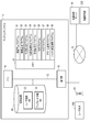
- FIG. 1 is a conceptual diagram for explaining the concept of a monitoring system to which the monitoring method according to the embodiment of the present invention is applied.
- the monitoring system 10 is a user terminal based on information uploaded from a terminal 100 (hereinafter referred to as "user terminal 100") carried by a watched person (for example, a target person to be watched like a child or an elderly person).
- a watched person for example, a target person to be watched like a child or an elderly person.
- the position of 100 is grasped, the living area of the watched person is determined based on the history of the position of the user terminal 100, and the positional relationship between the current position of the user terminal 100 and the living area is determined by the watcher (for example, the watched person).
- the terminal 200 hereinafter, referred to as "guardian terminal 200" of the guardian or supervisor of the watcher, hereinafter also referred to as "guardian").
- FIG. 2 is a schematic diagram showing an example of a functional configuration of a user terminal.
- the user terminal 100 transmits the SIM card 110, the transmission / reception function 120 capable of communicating with the monitoring system 10 via the base station 60 by a cellular system such as 3G, LTE (registered trademark), 4G, or 5G, and GPS information.
- the GPS function 130 to be acquired the WiFi function 140 to acquire the MAC address of the surrounding WiFi router together with the information indicating the reception strength (RSSI) of the radio wave received from the WiFi router, and the acceleration sensor to measure the acceleration of the user terminal 100.
- It includes a 150 and a rechargeable battery 160, such as a lithium ion battery, that supplies power to the user terminal 100. All of these apply well-known techniques and will not be discussed in further detail here.
- the user terminal 100 is not limited to directly communicating with the base station 60 by the transmission / reception function 120, but indirectly with the base station 60 by passing through the WiFi router 61 as shown by the broken line in FIG. You may communicate.
- the WiFi router 61 can be realized by, for example, a smartphone.
- the user terminal 100 may communicate with the monitoring system 10 by using a communication method other than the cellular system, such as LPWA (Low Power Wide Area).
- LPWA Low Power Wide Area
- the SIM card 110 is not required at the user terminal 100.
- the base station 60 is replaced with a gateway. In this way, depending on the communication method, the 60 becomes a base station or a gateway, but in the following, as an example, the user terminal 100 communicates with the monitoring system 10 by the cellular method, that is, via the base station 60. The form will be described.
- the user terminal 100 is lightweight and has a small size so that it will not be a burden even if it is carried by a child or an elderly person, and a unique identification number is set in advance for each user terminal 100.
- the monitoring system 10 In order to start using the monitoring system 10, it is first necessary to register the user terminal 100 in the monitoring system 10. User registration is performed by transmitting the identification number a of the user terminal 100 from the guardian terminal 200, which is a smartphone or a PC, to the monitoring system 10 via a communication network 70 such as the Internet.
- the guardian terminal 200 which is a smartphone or a PC
- the monitoring system 10 recognizes the user terminal 100 having the identification number a as the user terminal 100 to be monitored (watching target), and the guardian terminal 200 uses it to transmit the identification number a.
- the e-mail address is recognized as the address b of the guardian terminal 200 (hereinafter, also referred to as "guardian address b").
- the user terminal 100 awakens when the acceleration sensor 150 detects an acceleration equal to or higher than a predetermined value, that is, when the user terminal 100 moves, and is set by the GPS function 130, for example, by default. . Get GPS information at intervals such as every 5 minutes.
- the GPS information includes not only the position information but also a time stamp indicating the time at the time of determining the position.
- the user terminal 100 further uploads the acquired GPS information to the monitoring system 10 together with the identification number a of the user terminal 100 by using the transmission / reception function 120.
- the transmission / reception function 120 can acquire the battery remaining amount information from the battery 160, further add the battery remaining amount information, and upload it to the monitoring system 10.
- the user terminal 100 may be located in a place where the GPS function 130 cannot acquire GPS information.
- the user terminal 100 acquires the MAC addresses of a plurality of peripheral WiFi routers together with the reception strength information of the radio waves from each WiFi router by the WiFi function 140.
- the reception strength information also includes a time stamp indicating the time when the radio wave is transmitted from the WiFi router.
- the user terminal 100 monitors the acquired MAC addresses of the plurality of WiFi routers and the reception intensity information of the radio waves from each WiFi router from the transmission / reception function 120 together with the identification number a of the user terminal 100. Upload to 10.
- the MAC address of the WiFi router and the reception strength information of the radio wave from the WiFi router are used for the positioning performed by the positioning server 40, as will be described later.
- the user terminal 100 when the user terminal 100 is located in a place where the GPS function 130 cannot acquire GPS information, the user terminal 100 further receives radio waves from the base station 60 by the transmission / reception function 120, and instead of the GPS information, the base.
- the reception intensity information of the radio wave from the station 60 is uploaded from the transmission / reception function 120 to the monitoring system 10 via the base station 60 together with the identification number a of the user terminal 100 and the time stamp indicating the time when the radio wave is received from the base station 60. You can also do it.
- the reception intensity information of the radio wave from the base station 60 is also used for the positioning performed by the positioning server 40, as will be described later.
- the user terminal 100 selects either the MAC address of the WiFi router, the reception strength information of the radio wave from the WiFi router, the reception strength information of the radio wave from the base station 60, and the time stamp instead of the GPS information. Instead of uploading to the monitoring system 10, both can be uploaded to the monitoring system 10.
- the user terminal 100 can acquire GPS information, in addition to the GPS information, the MAC address of the WiFi router, the reception strength information of the radio wave from the WiFi router, and the reception of the radio wave from the base station 60 are received.
- the intensity information and the time stamp may be uploaded to the monitoring system 10.
- the monitoring system 10 has not only the position information determined from the GPS information but also the position information determined by the positioning server 40 based on the MAC address of the WiFi router and the reception intensity information of the radio wave from the WiFi router. , Any of the position information determined by the positioning server 40 based on the radio wave strength of the radio wave from the base station 60 can be used for positioning the user terminal 100.
- the user terminal 100 can acquire GPS information and receive radio waves from the WiFi router at the base station 60. It does not receive radio waves from the device and does not upload information to the monitoring system 10. In this way, when the user terminal 100 does not move, the user terminal 100 sleeps. This can save the power of the battery 160.
- the user terminal 100 does not have an operation button. All setting operations for the user terminal 100 (for example, setting or changing the interval for uploading) are performed remotely via the monitoring system 10 according to an instruction from the guardian terminal 200. Therefore, even if the watched person does not operate the user terminal 100 at all, the user terminal 100 automatically awakens / sleeps, and at the time of awakening, the information is uploaded to the monitoring system 10 at the set interval.
- FIG. 3 is a block diagram showing a configuration example of a monitoring system to which the monitoring method according to the embodiment of the present invention is applied.
- the monitoring system 10 includes a CPU 14, a communication unit 16, a storage device 20, and a memory 30 connected to each other by a bus 12.
- the CPU 14 is a computer and controls the internal operation of the monitoring system 10 according to various programs 31 to 39 stored in the memory 30.
- the communication unit 16 can receive the information uploaded from the user terminal 100 via the base station 60. Further, it is possible to communicate with the positioning server 40 and the guardian terminal 200 via a communication network 70 such as the Internet.
- an SSD Solid State Drive
- HDD Hard Disk Drive
- user registration DB 22 The registration database 22 (hereinafter referred to as "user registration DB" 22) and the upload information database 24 (hereinafter, "upload information DB") that stores the information uploaded from the user terminal 100 and the position information determined by the positioning server 40. 24) is memorized.
- the registration management program 31 performs the above-mentioned processing for user registration.
- User registration is performed by transmitting the identification number a of the user terminal 100 from the guardian terminal 200, which is a smartphone or a PC, to the monitoring system 10 via a communication network 70 such as the Internet.
- a communication network 70 such as the Internet.
- the transmitted identification number a is received by the communication unit 16, and the e-mail address used by the guardian terminal 200 to transmit the identification number a is recognized by the communication unit 16.
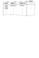
- FIG. 4 is a data structure diagram showing an example of a user registration DB.
- the user registration DB 22 includes the identification number a, the guardian address b, and the living area location information h as data items.
- the living area position information h is determined and written by the living area determination program 33, as will be described later.
- other information such as the address of the guardian and the start date of use of the user terminal 100 can be appropriately added as data items.
- the registration management program 31 writes the identification number a received by the communication unit 16 into the user registration DB 22. Further, the recognized e-mail address of the guardian terminal 200 is written in the user registration DB 22 as the guardian address b. This completes the user registration process.
- the monitoring system 10 can receive the information uploaded from the user terminal 100 having the identification number a.
- the information that can be uploaded includes the identification number a, GPS information, the MAC address of the WiFi router, the reception intensity information of the radio wave received by the user terminal 100 from the WiFi router and the time stamp indicating the reception time thereof, and the user terminal from the base station 60. It can include reception strength information of radio waves received by 100, battery remaining amount information, and the like.
- the user terminal 100 may not be able to receive any of GPS information, radio waves from the WiFi router, and radio waves from the base station 60. Therefore, for example, when the user terminal 100 cannot receive the GPS information, the uploaded information does not include the GPS information. On the other hand, when the user terminal 100 cannot receive the radio wave from the WiFi router, the uploaded information does not include the MAC address of the WiFi router and the reception strength information of the radio wave from the WiFi router. Further, when the user terminal 100 cannot receive the radio wave from the base station 60, the uploaded information does not include the reception strength information of the radio wave from the base station 60 and the time stamp indicating the reception time thereof.
- the information uploaded from the user terminal 100 at the set interval is received by the communication unit 16.
- the interval can be arbitrarily set and changed by the setting program 36 according to the instruction from the guardian terminal 200.
- the information storage program 32 writes the corresponding information in each data item specified in the upload information DB 24 based on the uploaded information.
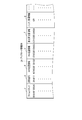
- FIG. 5 is a data structure diagram showing an example of the upload information DB.
- the upload information DB 24 includes time stamp c, identification number a, GPS position information d, WiFi position information e, base station position information f, battery remaining amount information g, and the like as data items.
- time stamp c identification number a
- GPS position information d GPS position information
- WiFi position information e WiFi position information
- base station position information f base station position information
- battery remaining amount information g battery remaining amount information g
- the MAC address of the WiFi router the reception strength of the radio wave from the WiFi router, the reception strength of the radio wave from the base station 60, and the like may be appropriately added as data items.
- the information storage program 32 stores the identification number a and the GPS information in the upload information DB 24 as the identification number a and the GPS position information d. Further, the time stamp included in the GPS information is stored in the upload information DB 24 as the time stamp c.
- the information storage program 32 uses the time stamp included in the reception intensity information as the time stamp c. While writing to the upload information DB 24, the MAC address and reception strength information are output from the communication unit 16 to the positioning server 40 via the communication network 70.
- the information storage program 32 writes the time stamp as the time stamp c in the upload information DB 24 and also writes the time stamp to the base station.
- the reception strength information of the radio wave from the station 60 is output to the positioning server 40 via the communication network 70.
- the positioning server 40 determines the position of the user terminal 100 based on these information, and obtains the corresponding position information (for example, latitude / longitude information).
- the WiFi position information e is returned to the communication unit 16 via the communication network 70.
- the positioning server 40 determines the position of the user terminal 100 based on this information, and the corresponding position information (for example, for example).
- the latitude / longitude information) is returned to the communication unit 16 as the base station position information f via the communication network 70.
- the monitoring system 10 can determine the position of the user terminal 100 even in a place where GPS signals cannot be acquired, such as a subway platform. Since such a positioning server 40 can be realized by using a known technique such as geoLocation provided by Google, further detailed description will be avoided.
- the information storage program 32 displays the WiFi position information e and / or the base station position information f with a corresponding time stamp. It is stored in the upload information DB 24 in association with.
- each user terminal 100 need only have the minimum required memory capacity, and the user The cost of the terminal 100 can be suppressed.
- the living area determination program 33 targets the location information d, e, f accumulated within a predetermined period among the location information d, e, and f stored in the upload information DB 24 based on the time stamp c. Determine the living area, which is the normal range of activity of the watcher. A default value such as the past 30 days is set for the predetermined period, but as described later, it is set to an arbitrary period by inputting necessary information from the guardian terminal 200 using the setting program 36. And can be changed.
- the living area determination program 33 further determines the living area more finely by using the position information d, e, f accumulated under the predetermined conditions among the position information d, e, f accumulated within the predetermined period. You can also do it.
- the predetermined condition For example, by setting the predetermined condition to weekdays, it is possible to determine the living area for weekdays only for the position information d, e, and f accumulated on weekdays based on the time stamp c. Further, by setting the predetermined condition to Saturdays, Sundays, and holidays, it is possible to determine the living area for Saturdays, Sundays, and holidays only for the position information d, e, and f accumulated on Saturdays, Sundays, and holidays based on the time stamp c. Furthermore, by setting a predetermined condition to a specific day of the week (for example, Friday), based on the time stamp c, only the position information d, e, and f accumulated on the specific day of the week are targeted for the specific day of the week. It is possible to determine the living area of the day of the week.
- a predetermined condition for example, Friday
- a specific time zone can be set as a predetermined condition.
- the living area on weekday mornings for example, 6 am to 10 am
- the daytime on weekdays for example, morning
- the living area determination program 33 includes a predetermined period, predetermined conditions, and further. Can determine various living areas according to the predetermined criteria described later.
- a predetermined period, a predetermined condition, and a predetermined standard may also be set and changed by making necessary inputs from the guardian terminal 200 using the setting program 36, as will be described later.
- a specific example of the process for determining the living area performed by the living area determination program 33 will be described with reference to the drawings.
- the living area is determined based on the position information d, e, and f accumulated in the past 30 days as a predetermined period.
- a predetermined condition such as a day of the week or a time zone
- only the position information to be considered is different, and the processing for determining the living area is the same. ..
- the living area determination program 33 has the location information d stored within a set predetermined period (for example, the past 30 days) among the location information d, e, and f of the specific user terminal 100 stored in the upload information DB 24. , E, f only.
- the living area determination program 33 can determine the living area by various methods as shown below by using any of the position information d, e, and f accumulated within a predetermined period.
- the living area determination program 33 determines the living area. Any one position information or one position information determined by appropriate weighting from a plurality of position information is used.
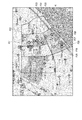
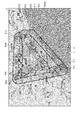
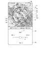
- FIG. 6 is a diagram for explaining an example of the first determination method of the living area.
- the living area is determined using a map divided into a plurality of sections in advance.
- the map illustrated in FIG. 6 is a well-known UTM grid map, and is divided by a plurality of square-shaped sections having a size corresponding to, for example, 100 meters in length and width.
- the living area determination program 33 determines as a living area a section to which the position information accumulated within a predetermined period belongs a predetermined number of times (for example, twice) or more among each section on such a map.
- plots P21 to P30 correspond to position information accumulated within a predetermined period
- plots P21, P22, and P24 are included in the compartment L3T3
- plots L3T2 are included in the plot L3T2.
- Plots P28, P29, P30 are included
- compartment L4T2 includes plots P25, P26, P27.
- the living area determination program 33 assigns the compartment L3T3, the compartment L3T2, and the compartment L4T2.
- the combined area is determined as the living area K.
- the compartment L3T4 contains only the plot P23, and the position information accumulated within the predetermined period belongs to, for example, only once, so that it is not regarded as the living area K.
- the map to be used is not necessarily limited to a map divided into squares like the UTM grid map, and is arbitrary. It is also possible to use a map divided into the shapes of, and for example, it is possible to determine a living area by using a map divided for each address, such as an address classification map. This will be described with reference to FIG.
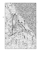
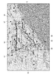
- FIG. 7 is a diagram for explaining another example of the first determination method of the living area.
- plots P21 to P30 correspond to the position information accumulated within a predetermined period, and plots P21 to P24 are included in 3-chome shown in FIG. 7, and plots P21 to P24 are included in 5-chome. Includes plots P25-P30.
- the living area determination program 33 determines the area where 3-chome and 5-chome are combined as the living area K.
- the living area determination program 33 can also determine the living area K by the second determination method as shown below.
- FIG. 8 is a diagram for explaining an example of the second determination method of the living area.
- the living area K can be determined by using the map divided into sections as shown in FIGS. 6 and 7, but the living area K is not divided into sections as shown in FIG.
- the living area K can also be determined by using the map.
- plots P21 to P30 correspond to the position information accumulated within a predetermined period, respectively.
- the living area determination program 33 determines the smallest convex area including all the plots P21 to P30 displayed on the map as the living area K, as illustrated in FIG. can do.
- the living area determination program 33 can also determine the living area K by the third determination method as shown below.
- FIG. 9 is a diagram for explaining an example of the third determination method of the living area.
- the living area K can be determined by using the map divided into sections as shown in FIGS. 6 and 7, but the living area K is not divided into sections as shown in FIG.
- the living area K can also be determined using the map.
- plots P21 to P30 correspond to the position information accumulated within a predetermined period, respectively.
- the living area determination program 33 determines the smallest circular area including all the plots P21 to P30 displayed on the map as the living area K, as illustrated in FIG. You can also do it.
- the living area determination program 33 can also determine the living area K by the fourth determination method as shown below.
- FIG. 10 is a diagram for explaining an example of the fourth determination method of the living area.
- the living area K can be determined by using the map divided into sections as shown in FIGS. 6 and 7, but the living area K is not divided into sections as shown in FIG.
- the living area K can also be determined using the map.
- plots P21 to P30 correspond to the position information accumulated within a predetermined period, respectively.
- the living area determination program 33 sets the area represented by the smallest rectangular shape including all the plots P21 to P30 displayed on the map as the living area K, as illustrated in FIG. Can be determined as.
- the living area determination program 33 can also determine the living area K by the fifth determination method as shown below.
- FIG. 11 is a diagram for explaining an example of the fifth determination method of the living area.
- the living area K can be determined by using the map divided into sections as shown in FIGS. 6 and 7, but the living area K is not divided into sections as shown in FIG.
- the living area K can also be determined using the map.
- the plots indicated by the water droplet marks correspond to the position information accumulated within a predetermined period.
- the living area determination program 33 determines the smallest area including all the plots displayed on the map as the living area K, as illustrated in FIG. For this purpose, some plots P11 to P15 that will be located on the outermost side of the living area K are selected from the displayed plots, and only the selected plots are targeted, and a straight line is drawn between adjacent plots. The area formed by connecting with L is determined as the living area K.
- the living area determination program 33 can also determine the living area K by the sixth determination method as shown below.
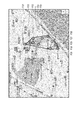
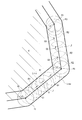
- FIG. 12 is a diagram for explaining an example of the sixth determination method of the living area.
- the living area determination program 33 determines the living area K by using the route of a road or a railroad. Therefore, it is necessary to use a map that contains information on road and rail routes. As long as information on road and railroad routes is included, life can be achieved by using a map divided into sections as shown in FIGS. 6 and 7, or by using a map not divided into sections. Area K can be determined.
- the plots indicated by the water droplet marks correspond to the position information accumulated within a predetermined period.
- the living area determination program 33 targets all the plots displayed on the map, and establishes an area formed by connecting adjacent plots along a road or railroad route. Determined as living area K. Therefore, the line ⁇ connecting adjacent plots does not always become a straight line L as shown in FIG. 11, but may become a straight line along the route of a road or a railroad, for example, as illustrated in FIG. , Can be curved.
- the method for determining the living area K as described above is only an example, and even if a part of one of the determination methods is modified to determine the living area K, or a method that combines a plurality of determination methods is used for living.
- the sphere K may be determined, or another determination method may be adopted to determine the living sphere K.
- the plot circle can also be determined as a living area.
- the living area determination program 33 writes the position information defining the living area K thus determined as the living area position information h of the corresponding identification number a in the user registration DB 22.
- the map information creation program 34 creates the map information in which the living area K is specified on the map based on the living area position information h written in the user registration DB 22. Then, when there is a request from the guardian terminal 200, this map information is transmitted from the communication unit 16 to the guardian terminal 200 via the communication network 70.
- the guardian can display the map information transmitted to the guardian terminal 200 from the display screen of the guardian terminal 200. As a result, the guardian can visually grasp the living area K of the watched person.
- the guardian thinks that the living area K determined in this way is not appropriate and wants to correct it, he / she can correct the living area K by using the setting program 36.
- the setting screen M as shown in FIG. 13 is displayed from the display screen of the guardian terminal 200 of the requesting source.
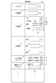
- FIG. 13 is a schematic diagram showing an example of the setting screen.
- an interval i a predetermined period t, a predetermined condition u (weekdays u1, Saturdays, Sundays, and holidays u2, a day of the week u3, a time zone u4), a predetermined reference v (radius v1, length v2, Each item for inputting the radius v3), the remaining battery level option x, and the forced sleep option y is shown.
- the guardian uses the input function of the guardian terminal 200 to input a numerical value from the setting screen M, or by selecting a desired content from the options prepared in advance, the interval i, predetermined Period t, predetermined condition u (weekdays u1, Saturdays, Sundays, and holidays u2, day of the week u3, time zone u4), predetermined reference v (radius v1, length v2, radius r3), battery level option x, forced sleep option y, etc. It can be set in the monitoring system 10.
- the setting contents of the interval i, the battery remaining amount option x, and the forced sleep option y are transmitted from the monitoring system 10 to the user terminal 100 via the communication unit 16 and received by the transmission / reception function 120 of the user terminal 100. , Set in the user terminal 100.
- the necessary items may be appropriately increased on the setting screen M to enable further various settings for the monitoring system 10.
- the monitoring system 10 can also determine a plurality of living areas K as described below.
- the monitoring system 10 can determine the living area for each predetermined condition u, such as the living area for weekdays, the living area for weekends and holidays, the living area on a specific day of the week, and the living area at a specific time zone. There is.
- the living area determination program 33 determines the living area K for weekdays only for the position information uploaded to the upload information DB 24 on weekdays within the predetermined period t. be able to.
- the living area determination program 33 targets only the location information uploaded to the upload information DB 24 on Saturdays, Sundays, and holidays within the predetermined period t, and the living area K for weekdays. Can be determined.
- the time zone u4 can be set independently, or can be set in combination with any of weekdays u1, Saturdays, Sundays, and holidays u2, and specific days of the week u3. For example, if "Tuesday" is specified in the input field u32 and "10:00" to "17:00" is selected or input in the time zone u4, the living area determination program 33 will be in the predetermined period t.
- the living area K can be determined only for the location information uploaded to the upload information DB 24 between 10:00 and 17:00 on Tuesday.
- the setting program 36 narrows down the target position information for determining the living area K and determines the living area. Since the program 33 determines the living area K based on the narrowed down position information, it is possible to finely set the living area K based on the time condition.
- the monitoring system 10 can also expand or contract the determined living area K. This function will be described below.
- the guardian In general, children have a wider range of activities as they grow up. On the contrary, the range of action of old people becomes narrower with age. Therefore, if the guardian is a child, the guardian may want to expand the living area K determined by the living area determination program 33 as the child grows. On the other hand, conversely, if the watcher is an elderly person, he / she may want to reduce the living area K determined by the living area determination program 33.
- the monitoring system 10 has a function of expanding or reducing the living area K once determined by the living area determination program 33 in response to a request from the guardian terminal 200. .. This is possible by setting a value in the predetermined reference v column (radius v1, length v2, radius v3) of the setting screen M displayed by the setting program 36. Specific examples will be described with reference to FIGS. 9, 10, and 11 described above.
- FIG. 9 shows the living area K defined by the smallest circular shape.
- the setting program 36 changes the size of the circular living area K to the living area determination program 33 concentrically according to the designated input.
- the living area determination program 33 can redetermine the living area K by expanding or contracting the circular living area K.
- the living area Kmax redetermined by expanding the living area K is illustrated together with the living area K before the redetermination.
- FIG. 10 shows the living area K defined by the smallest rectangular shape.
- FIG. 11 shows a living area K having an arbitrary shape defined as the minimum area including all location information.
- the expanded living area Kmax and the reduced living area Kmin are determined. This will be generally described with reference to FIG.
- FIG. 14 is a schematic diagram illustrating a part of a straight line that defines the outer circumference of the living area.
- the straight line L1 connecting the plot P1 and the plot P2 and the straight line L2 connecting the plot P2 and the plot P3 are a part of the straight line L defining the outer circumference of the living area K.
- the living area determination program 33 can redetermine the living area K by increasing or decreasing the size even if the living area K has an arbitrary shape.
- the living area Kmax expanded and the living area Kmin reduced by such redetermination are illustrated together with the living area K before the redetermination.
- FIG. 15 is a schematic diagram showing a display example on the display screen of the guardian terminal for setting a predetermined standard.
- FIG. 15 shows an example of a state in which a setting screen used as a substitute for the setting screen M is displayed from the display screen of the guardian terminal 200 when the setting program 36 is started.
- a map display unit M1 On this display screen, a map display unit M1, a slider display unit M2, and a setting determination unit M3 are displayed.
- the circular living area K as illustrated in FIG. 9 is displayed on the map display unit M1.
- the slider N for setting the value of the radius v1 of the predetermined reference v is displayed on the slider display unit M2.
- the guardian specifies the value of the radius v1 by moving the slider N using the input function (for example, the touch panel function) of the guardian terminal 200, and presses the setting button of the setting determination unit M3.
- the value of radius v1 can be transmitted to the monitoring system 10.
- the living area K is redetermined by the living area determination program 33 according to the transmitted value of the radius v1, and the expanded living area Kmax and the reduced living area Kmin are displayed from the map display unit M1.
- the guardian can input the conditions for determining the living area K.
- the monitoring system 10 also provides a living area modification program 35 for allowing parents to arbitrarily set the living area K.
- FIG. 16 is map information for explaining the method of setting the living area by the living area correction program.
- the location information targeted for determining the living area K is determined from the guardian terminal 200 as illustrated in FIG.
- the map information S showing the plot corresponding to is displayed.
- the guardian can specify the range B1 to B8 of the living area K by tracing the display screen with a finger.
- the guardian may specify the range B1 to B8 of the living area K with reference to the displayed plot, or may specify the range B1 to B8 of the living area K regardless of the displayed plot.
- B8 can be arbitrarily specified.
- the guardian transmits the map information S in which the range B1 to B8 of the living area K is designated from the guardian terminal 200 to the monitoring system 10.
- the map information S for which the ranges B1 to B8 are specified is received by the communication unit 16.
- the communication unit 16 also recognizes the guardian address b of the guardian terminal 200 of the transmission source.
- the living area modification program 35 refers to the user registration DB 22 and obtains the living area position information h of the recognized guardian address b. , The user registration DB 22 is updated by updating to the living area position information determined by the designated ranges B1 to B8.
- the living area modification program 35 enables the guardian to arbitrarily determine the living area K.
- the determination program 37 determines the user based on the information uploaded from the user terminal 100 after the living area K (including the expanded living area Kmax and the reduced living area Kmin) is determined as described above. Based on the position information d, e, and f of the terminal 100, the positional relationship between the position of the user terminal 100 and the living area K, for example, the position of the user terminal 100 is inside the living area K or the living area K. Determine if it is outside of.
- new information is uploaded from the user terminal 100, and new information (time stamp c, identification information a, GPS position information d, WiFi position information e, base station position information) is uploaded to the upload information DB 24. Every time f, battery remaining amount information g, etc.) is written, the user registration DB 22 is referred to, and the living area position information h of the user terminal 100 having the corresponding identification number a is acquired from the upload information DB 24. Then, by comparing at least one of the GPS position information d, the WiFi position information e, and the base station position information f written in the upload information DB 24 with the living area position information h, the position of the user terminal 100 Is inside the living area K or outside the living area K.
- the determination program 37 is any one. By comparing one position information or one position information determined by appropriate weighting from a plurality of position information with the living area position information h, the position of the user terminal 100 is inside the living area K. Or is outside the living area K.
- the alarm notification program 38 notifies the guardian terminal 200 of an alarm by sound or display. As a result, the guardian can quickly and surely grasp that the watched person has deviated from the living area K.
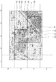
- the map information creation program 34 sets the living area K and the living area K as illustrated in FIG. Map information S displaying the current position H of the user terminal 100 is created and transmitted to the guardian terminal 200 via the communication unit 16.
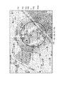
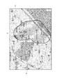
- FIG. 17 is a conceptual diagram showing an example of map information displaying the positional relationship between the living area and the current position of the user terminal.
- the map information creation program 34 is a map showing the position H of the user terminal 100 at any time and time zone in the present and past in response to a request from the guardian terminal 200, regardless of the determination result by the determination program 37.
- Information S can also be created and transmitted to the guardian terminal 200 via the communication unit 16.
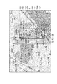
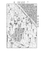
- the guardian terminal 200 not only displays the current position of the user terminal 100, but also the movement history (plot P21 ⁇ P22 ⁇ ... ⁇ P30) of the user terminal 100 for a certain period (for example, a certain day). It is also possible to check on the map. An example of this is shown in FIG.
- FIG. 18 is a schematic diagram showing an example of map information in which the movement history of the user terminal is displayed.
- the guardian By displaying the map information S as illustrated in FIG. 18 from the display screen of the guardian terminal 200, the guardian displays the movement history (plot P21 ⁇ ) of the user terminal 100 for a certain period (for example, a certain day). P22 ⁇ ... ⁇ P30) can be confirmed.
- the monitoring system 10 has a function of setting the living area K of the watched person and notifying the guardian that the position of the user terminal 100 is outside the living area K.
- the monitoring system 10 also has a battery level option x and a forced sleep option y as optional functions.
- the battery level option x is provided by the battery level grasping program 39.
- the battery remaining amount grasping program 39 refers to the upload information DB 24 and acquires the battery remaining amount information g. Then, based on the battery remaining amount information g, it is determined whether or not the battery remaining amount of the user terminal 100 is less than a preset predetermined amount (for example, the remaining 20%).
- the battery level level grasping program 39 sets the battery level to a predetermined amount. If it is determined that the value is lower, the alarm notification program 38 refers to the user registration DB 22 and recognizes the guardian address b of the corresponding identification number a, and tells the guardian terminal 200, for example, "remaining battery level”. Notify me with messages such as "I'm running low" or "Please charge”.
- the guardian can grasp from this message sent to the guardian terminal 200 that the battery level of the user terminal 100 is low.
- the guardian can charge the battery 160 of the user terminal 100 if the battery 160 of the user terminal 100 can be charged on the spot.
- the setting program 36 is activated from the guardian terminal 200 to reduce the consumption of the battery 160 and extend the operating time of the user terminal 100 from the setting screen M.
- You can also instruct the interval i to be longer (eg, 1.5 to 3 minutes).
- the time zone y2 for forcibly putting the user terminal 100 to sleep can be set from the forced sleep option y column. Thereby, in order to suppress the consumption of the battery 160 of the user terminal 100, for example, it is possible to set the time zone y2 for forcibly putting the user terminal 100 to sleep while the watcher is at school.
- the remaining battery information g of the upload information DB 24 reflects the remaining battery information, so that the battery remaining amount grasping program According to 39, it is recognized that the remaining battery level is sufficient. If it is specified in the battery remaining amount option x field on the setting screen M to notify x2 when the charging of the battery 160 is completed, the alarm notification program 38 causes the user terminal 100 to "charge the battery.” The message "Completed" is notified to the parent terminal 200.
- the user terminal 100 In order to start using the user terminal 100, it is first necessary to register the user by transmitting the identification number a of the user terminal 100 to the monitoring system 10. User registration is performed by transmitting the identification number a of the user terminal 100 from the guardian terminal 200, which is a smartphone or a PC, to the monitoring system 10 via a communication network 70 such as the Internet.
- the guardian terminal 200 which is a smartphone or a PC
- the transmitted identification number a is received by the communication unit 16, and the e-mail address of the guardian terminal 200 is recognized by the communication unit 16 as the guardian address b.
- the identification number a received by the communication unit 16 and the recognized guardian address b are written to the user registration DB 22 by the registration management program 31. This completes the user registration process.
- the identification number, GPS information, the MAC address of the WiFi router, and the radio wave from the WiFi router are sent from the user terminal 100 to the monitoring system 10 by the interval i set, for example, every 1.5 minutes. It is possible to upload information such as reception strength information of the above, reception strength information of radio waves from the base station 60, and remaining battery information.
- the interval i can be set by inputting a desired value from the guardian terminal 200 on the setting screen M displayed by the setting program 36.
- the information uploaded from the user terminal 100 is received by the communication unit 16, and the information storage program 32 writes the corresponding information in each data item in the upload information DB 24.
- the uploaded information includes the MAC address of the WiFi router, the reception strength information of the radio wave from the WiFi router, and the reception strength information of the radio wave from the base station 60, these information are used in the information storage program 32. Is output from the communication unit 16 to the positioning server 40 via the communication network 70.
- the position of the user terminal 100 is determined based on the information, and the corresponding position is determined.
- the position information (for example, latitude / longitude information) is returned to the communication unit 16 as WiFi position information e via the communication network 70.
- the positioning server 40 when the reception strength information of the radio wave from the base station 60 is transmitted from the communication unit 16, the position of the user terminal 100 is determined based on this information, and the corresponding position information (for example, for example).
- the latitude / longitude information) is returned to the communication unit 16 as the base station position information f via the communication network 70.
- the WiFi position information e and / or the base station position information f returned from the positioning server 40 is stored in the upload information DB 24 in association with the corresponding time stamp c by the information storage program 32.
- the living area K is determined by the living area determination program 33, and based on the determined living area K, the determination program 37 determines the user terminal 100. , The positional relationship with the living area K is determined.
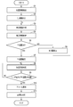
- FIG. 19 is a flowchart showing a flow of processing related to determination of the living area and determination of the positional relationship between the user terminal and the living area.
- the living area is determined based on the position information extracted in step S1 (S2).
- a plurality of types of position information for example, at least two of the position information d, the position information e, and the position information f
- the time stamps c that can be regarded as the same or the same, any of them.
- the specific method for determining the living area is not limited, and for example, as described with reference to FIGS. 6 and 7, the position information accumulated within a predetermined period among a plurality of sections on the map
- the living area K is determined by connecting the sections to which the divisions belong more than a predetermined number of times (for example, twice).
- the smallest convex area including all plots P21 to P30 displayed on the map is determined as the living area K.
- the area represented by the smallest circle including all the plots P21 to P30 displayed on the map is determined as the living area K.
- the area shown by the smallest rectangular shape including all the plots P21 to P30 displayed on the map is determined as the living area K.
- representative plots P11 to P15 located on the outermost side of the living area K are selected, and only the selected plots P11 to P15 are targeted, and the adjacent plots are linearly connected.
- the area containing all the plots is determined as the living area K by, or by connecting along the road or railroad route.
- the monitoring system 10 determines a plurality of living areas for each predetermined condition, such as a living area for u1 on weekdays, a living area for u2 on weekends and holidays, a living area on a specific day of the week u3, and a living area on a specific time zone u4. You can also do it.
- the position information that defines the living area K is written as the living area position information h of the corresponding identification number a in the user registration DB 22.
- the map information creation program 34 acquires the living area position information h registered for the user according to the corresponding identification number a from the user registration DB 22, and based on the acquired living area position information h, the living area.
- Map information S in which K is specified on the map is created, and is transmitted to the guardian terminal 200 via the communication unit 16 in response to a request from the guardian terminal 200 (S3).
- the map information S transmitted to the guardian terminal 200 is displayed from the display screen of the guardian terminal 200 (S4). As a result, the guardian can visually grasp the living area K of the watched person.
- the guardian can change the living area K by looking at such map information S. If it is not changed (S5: Yes), the living area K is determined (S7). On the other hand, when the guardian wants to change the living area K (S5: No), the guardian inputs values in the predetermined period t, the predetermined condition u, and the predetermined reference v from the setting screen M as shown in FIG. Alternatively, as shown in FIG. 15, the living area K can be changed by tracing the living area K displayed from the display screen of the guardian terminal 200 with a finger on the display screen (S6). ..
- the living area position information h of the user registration DB 22 is updated according to the changed living area K, and the process returns to step S3.
- new information (time stamp c, identification information a, GPS position information d,) is added to the upload information DB 24. Every time the WiFi position information e, the base station position information f, the battery remaining amount information g, etc. are written, the position information of the user terminal 100 is compared with the living area position information h by the determination program 37, so that the user It is determined whether the position of the terminal 100 is inside the living area K or outside the living area K (S8).
- the map information creation program 34 creates map information S displaying the living area K and the current position H of the user terminal 100, as illustrated in FIG. 17, and the communication unit It is transmitted to the guardian terminal 200 via 16. As a result, the guardian can grasp the current position of the guardian.
- the alarm notification program 38 sends a sound to the guardian terminal 200. An alarm is notified by the display (S10). As a result, the guardian can quickly and surely grasp that the watched person has deviated from the living area K and take necessary measures (S11).
- the monitoring system 10 can provide a function for the guardian to arbitrarily set a predetermined period t, a predetermined condition u, and a predetermined reference v for determining the living area K. Furthermore, when the position of the user terminal 100 deviates from the living area K, it can be detected and notified to the guardian by an alarm or the like, so that the guardian can almost move the watched person out of the normal action range. It will be possible to grasp it reliably in real time.
- the invention of the present application is not limited to the above embodiment, and can be variously modified at the implementation stage without departing from the gist thereof.
- each embodiment may be carried out in combination as appropriate as possible, in which case the combined effect can be obtained.
- the above-described embodiment includes inventions at various stages, and various inventions can be extracted by an appropriate combination in a plurality of disclosed constituent requirements.
Landscapes
- Business, Economics & Management (AREA)
- Engineering & Computer Science (AREA)
- Health & Medical Sciences (AREA)
- General Health & Medical Sciences (AREA)
- Computer Networks & Wireless Communication (AREA)
- Signal Processing (AREA)
- Child & Adolescent Psychology (AREA)
- Physics & Mathematics (AREA)
- General Physics & Mathematics (AREA)
- Emergency Management (AREA)
- Tourism & Hospitality (AREA)
- Economics (AREA)
- Theoretical Computer Science (AREA)
- Human Resources & Organizations (AREA)
- Marketing (AREA)
- Primary Health Care (AREA)
- Strategic Management (AREA)
- General Business, Economics & Management (AREA)
- Radar, Positioning & Navigation (AREA)
- Alarm Systems (AREA)
- Telephonic Communication Services (AREA)
- Emergency Alarm Devices (AREA)
- Medical Treatment And Welfare Office Work (AREA)
- Management, Administration, Business Operations System, And Electronic Commerce (AREA)
- Telephone Function (AREA)
Priority Applications (15)
| Application Number | Priority Date | Filing Date | Title |
|---|---|---|---|
| PCT/JP2019/014550 WO2020202449A1 (ja) | 2019-04-01 | 2019-04-01 | モニタリングシステム、モニタリング方法、およびプログラム |
| EP19922947.7A EP3951735A4 (en) | 2019-04-01 | 2019-04-01 | MONITORING SYSTEM, MONITORING PROCEDURE AND PROGRAM |
| JP2021511815A JP7381114B2 (ja) | 2019-04-01 | 2019-04-01 | モニタリングシステム |
| CN201980095133.2A CN113711281A (zh) | 2019-04-01 | 2019-04-01 | 监视系统、监视方法以及程序 |
| US17/486,263 US11954992B2 (en) | 2019-04-01 | 2021-09-27 | Monitoring system, monitoring method, and program |
| JP2023184289A JP7442905B2 (ja) | 2019-04-01 | 2023-10-26 | モニタリングシステム、モニタリング方法、およびプログラム |
| JP2024011895A JP7553163B2 (ja) | 2019-04-01 | 2024-01-30 | モニタリングシステム、モニタリング方法、およびプログラム |
| US18/586,288 US12387584B2 (en) | 2019-04-01 | 2024-02-23 | Monitoring system, monitoring method, and program |
| JP2024147591A JP2025011072A (ja) | 2019-04-01 | 2024-08-29 | モニタリングシステム、モニタリング方法、およびプログラム |
| JP2024200746A JP2025020438A (ja) | 2019-04-01 | 2024-11-18 | モニタリングシステム、モニタリング方法、およびプログラム |
| JP2025019800A JP7659877B1 (ja) | 2019-04-01 | 2025-02-10 | モニタリングシステム、モニタリング方法、およびプログラム |
| JP2025019801A JP7680105B2 (ja) | 2019-04-01 | 2025-02-10 | モニタリングシステム、モニタリング方法、およびプログラム |
| JP2025074401A JP7728622B2 (ja) | 2019-04-01 | 2025-04-28 | モニタリングシステム、モニタリング方法、およびプログラム |
| US19/266,032 US20250342760A1 (en) | 2019-04-01 | 2025-07-10 | Monitoring system, monitoring method, and program |
| JP2025130380A JP7763556B2 (ja) | 2019-04-01 | 2025-08-05 | モニタリングシステム、モニタリング方法、およびプログラム |
Applications Claiming Priority (1)
| Application Number | Priority Date | Filing Date | Title |
|---|---|---|---|
| PCT/JP2019/014550 WO2020202449A1 (ja) | 2019-04-01 | 2019-04-01 | モニタリングシステム、モニタリング方法、およびプログラム |
Related Child Applications (1)
| Application Number | Title | Priority Date | Filing Date |
|---|---|---|---|
| US17/486,263 Continuation US11954992B2 (en) | 2019-04-01 | 2021-09-27 | Monitoring system, monitoring method, and program |
Publications (1)
| Publication Number | Publication Date |
|---|---|
| WO2020202449A1 true WO2020202449A1 (ja) | 2020-10-08 |
Family
ID=72666198
Family Applications (1)
| Application Number | Title | Priority Date | Filing Date |
|---|---|---|---|
| PCT/JP2019/014550 Ceased WO2020202449A1 (ja) | 2019-04-01 | 2019-04-01 | モニタリングシステム、モニタリング方法、およびプログラム |
Country Status (5)
| Country | Link |
|---|---|
| US (3) | US11954992B2 (enExample) |
| EP (1) | EP3951735A4 (enExample) |
| JP (9) | JP7381114B2 (enExample) |
| CN (1) | CN113711281A (enExample) |
| WO (1) | WO2020202449A1 (enExample) |
Cited By (2)
| Publication number | Priority date | Publication date | Assignee | Title |
|---|---|---|---|---|
| JP2025169992A (ja) * | 2023-10-20 | 2025-11-14 | ビーサイズ株式会社 | 情報処理装置、情報処理端末、情報処理方法、情報処理プログラム |
| JP7792037B1 (ja) | 2025-06-19 | 2025-12-24 | ジオテクノロジーズ株式会社 | 情報処理方法、情報処理プログラム、情報処理装置、および情報処理システム |
Families Citing this family (2)
| Publication number | Priority date | Publication date | Assignee | Title |
|---|---|---|---|---|
| CN113711281A (zh) * | 2019-04-01 | 2021-11-26 | 比赛斯株式会社 | 监视系统、监视方法以及程序 |
| CN115273395B (zh) * | 2022-05-31 | 2024-03-12 | 歌尔股份有限公司 | 监控方法、装置、设备、系统及存储介质 |
Citations (2)
| Publication number | Priority date | Publication date | Assignee | Title |
|---|---|---|---|---|
| JP2002269653A (ja) * | 2001-03-07 | 2002-09-20 | Omron Corp | 監視装置および方法 |
| JP2013105457A (ja) * | 2011-11-16 | 2013-05-30 | Zenrin Datacom Co Ltd | 日常圏設定システム、日常圏設定方法及び日常圏設定プログラム |
Family Cites Families (36)
| Publication number | Priority date | Publication date | Assignee | Title |
|---|---|---|---|---|
| JP2007249665A (ja) * | 2006-03-16 | 2007-09-27 | Nec Corp | 異常状態通知システム、通知サーバ及び異常状態通知方法 |
| JP4820723B2 (ja) * | 2006-09-12 | 2011-11-24 | 富士通株式会社 | 通信制御システム |
| US8634813B2 (en) * | 2006-11-28 | 2014-01-21 | Verizon Patent And Licensing Inc. | Method and system for monitoring a mobile device over a video network |
| JP2009053171A (ja) * | 2007-08-29 | 2009-03-12 | Panasonic Corp | 表示システム、表示方法およびプログラム |
| CN101754435A (zh) * | 2010-01-22 | 2010-06-23 | 北京邮电大学 | 一种适用于无线局域网wlan的终端定位方法 |
| JP2012221267A (ja) * | 2011-04-11 | 2012-11-12 | Genetec Corp | 居場所確認方法 |
| CN102291674A (zh) * | 2011-07-25 | 2011-12-21 | 盛乐信息技术(上海)有限公司 | 一种基于Wi-Fi的无线定位方法与系统 |
| US20130225196A1 (en) * | 2012-02-27 | 2013-08-29 | Bryan J. James | Geo-Fence Generation and Updating Based on Device Movement Patterns |
| JP5851328B2 (ja) * | 2012-04-27 | 2016-02-03 | 京セラ株式会社 | 携帯通信装置、通信方法、及び通信プログラム |
| WO2014063121A1 (en) * | 2012-10-19 | 2014-04-24 | Mcafee, Inc. | Personal safety and emergency services |
| JP5910549B2 (ja) * | 2013-03-15 | 2016-04-27 | 富士通株式会社 | 監視装置、監視システムおよび監視方法 |
| US9123244B2 (en) * | 2013-03-15 | 2015-09-01 | Denso International America, Inc. | Vehicle tracking of personal devices with response system |
| JP2014186402A (ja) * | 2013-03-21 | 2014-10-02 | Toshiba Corp | 生活見守り支援装置 |
| JP2015114863A (ja) * | 2013-12-12 | 2015-06-22 | 株式会社日立システムズエンジニアリングサービス | 見守りシステム |
| US9485206B2 (en) | 2013-12-19 | 2016-11-01 | Websafety, Inc. | Devices and methods for improving web safety and deterrence of cyberbullying |
| JP5937146B2 (ja) | 2014-06-19 | 2016-06-22 | ソフトバンク株式会社 | 遺失物捜索システム及び制御方法 |
| US9875638B2 (en) * | 2014-10-28 | 2018-01-23 | Numerex Corp. | Method and system for generating geofences for managing offender movement |
| US20190213860A1 (en) * | 2014-11-25 | 2019-07-11 | Fynd Technologies, Inc. | Geolocation bracelet, system, and methods |
| US10397751B2 (en) * | 2014-11-25 | 2019-08-27 | Fynd Technologies, Inc. | Geolocation bracelet, system, and methods |
| CN107408330B (zh) * | 2015-03-26 | 2019-07-23 | 柯尼卡美能达株式会社 | 被监视者监视系统的显示装置及其显示方法以及被监视者监视系统 |
| EP3319058A4 (en) * | 2015-06-30 | 2018-06-27 | Fujitsu Limited | Anomaly detection method, anomaly detection program, and information processing device |
| KR20170009265A (ko) * | 2015-07-16 | 2017-01-25 | 황민섭 | 유아 및 어린이용 블랙박스 장치, 이를 이용한 안전관리 시스템 및 그 방법 |
| JP2017045252A (ja) * | 2015-08-26 | 2017-03-02 | パイオニア株式会社 | 情報処理装置、情報処理方法、情報処理プログラム及び記録媒体 |
| JP2017194786A (ja) | 2016-04-19 | 2017-10-26 | 株式会社Technology Gateway | Gpsトラッキングデバイス |
| JP2018022344A (ja) * | 2016-08-03 | 2018-02-08 | セゾン自動車火災保険株式会社 | 検知装置、運転挙動検知システム、運転挙動検知方法、運転挙動検知プログラム |
| JP6698009B2 (ja) * | 2016-12-27 | 2020-05-27 | 株式会社ゼンリンデータコム | 情報処理装置、情報処理方法、及びプログラム |
| CN106612494A (zh) * | 2017-01-20 | 2017-05-03 | 泉州奇鹭物联网科技有限公司 | 一种智能追踪定位方法及系统 |
| JP2018129598A (ja) | 2017-02-07 | 2018-08-16 | スター精密株式会社 | 位置情報管理システム及びそれに用いられる携帯機器 |
| JP2017130209A (ja) | 2017-02-14 | 2017-07-27 | 株式会社サテライト | 行動管理装置、情報端末、行動管理方法、情報処理方法、コンピュータプログラム |
| JP6188981B1 (ja) * | 2017-02-28 | 2017-08-30 | 株式会社ラエン | 捜索システム |
| EP3614331B1 (en) | 2017-04-21 | 2023-05-31 | Sony Group Corporation | Information processing device, information processing method, and program |
| JP6912271B2 (ja) * | 2017-05-17 | 2021-08-04 | 株式会社Nttドコモ | デバイス位置管理システム及びデバイス位置管理サーバ |
| JP6541189B2 (ja) * | 2017-06-20 | 2019-07-10 | 寛昌 澤和 | 送信装置および捜索システム |
| JP6379271B1 (ja) | 2017-12-04 | 2018-08-22 | ソフィア総合研究所株式会社 | 見守りシステム、見守り方法、見守り端末、サーバ、およびプログラム |
| CN108650630A (zh) * | 2018-05-08 | 2018-10-12 | 深圳市零度智控科技有限公司 | 通讯定位方法、定位终端、通讯定位系统及可读存储介质 |
| CN113711281A (zh) * | 2019-04-01 | 2021-11-26 | 比赛斯株式会社 | 监视系统、监视方法以及程序 |
-
2019
- 2019-04-01 CN CN201980095133.2A patent/CN113711281A/zh active Pending
- 2019-04-01 WO PCT/JP2019/014550 patent/WO2020202449A1/ja not_active Ceased
- 2019-04-01 EP EP19922947.7A patent/EP3951735A4/en active Pending
- 2019-04-01 JP JP2021511815A patent/JP7381114B2/ja active Active
-
2021
- 2021-09-27 US US17/486,263 patent/US11954992B2/en active Active
-
2023
- 2023-10-26 JP JP2023184289A patent/JP7442905B2/ja active Active
-
2024
- 2024-01-30 JP JP2024011895A patent/JP7553163B2/ja active Active
- 2024-02-23 US US18/586,288 patent/US12387584B2/en active Active
- 2024-08-29 JP JP2024147591A patent/JP2025011072A/ja active Pending
- 2024-11-18 JP JP2024200746A patent/JP2025020438A/ja active Pending
-
2025
- 2025-02-10 JP JP2025019800A patent/JP7659877B1/ja active Active
- 2025-02-10 JP JP2025019801A patent/JP7680105B2/ja active Active
- 2025-04-28 JP JP2025074401A patent/JP7728622B2/ja active Active
- 2025-07-10 US US19/266,032 patent/US20250342760A1/en active Pending
- 2025-08-05 JP JP2025130380A patent/JP7763556B2/ja active Active
Patent Citations (2)
| Publication number | Priority date | Publication date | Assignee | Title |
|---|---|---|---|---|
| JP2002269653A (ja) * | 2001-03-07 | 2002-09-20 | Omron Corp | 監視装置および方法 |
| JP2013105457A (ja) * | 2011-11-16 | 2013-05-30 | Zenrin Datacom Co Ltd | 日常圏設定システム、日常圏設定方法及び日常圏設定プログラム |
Cited By (2)
| Publication number | Priority date | Publication date | Assignee | Title |
|---|---|---|---|---|
| JP2025169992A (ja) * | 2023-10-20 | 2025-11-14 | ビーサイズ株式会社 | 情報処理装置、情報処理端末、情報処理方法、情報処理プログラム |
| JP7792037B1 (ja) | 2025-06-19 | 2025-12-24 | ジオテクノロジーズ株式会社 | 情報処理方法、情報処理プログラム、情報処理装置、および情報処理システム |
Also Published As
| Publication number | Publication date |
|---|---|
| EP3951735A1 (en) | 2022-02-09 |
| JP7659877B1 (ja) | 2025-04-10 |
| JP7442905B2 (ja) | 2024-03-05 |
| JP7763556B2 (ja) | 2025-11-04 |
| EP3951735A4 (en) | 2022-11-09 |
| JP2025105853A (ja) | 2025-07-10 |
| US20250342760A1 (en) | 2025-11-06 |
| JP2025067937A (ja) | 2025-04-24 |
| JP2024038507A (ja) | 2024-03-19 |
| JP2025011072A (ja) | 2025-01-23 |
| JPWO2020202449A1 (ja) | 2021-12-23 |
| JP7728622B2 (ja) | 2025-08-25 |
| US12387584B2 (en) | 2025-08-12 |
| JP2024010119A (ja) | 2024-01-23 |
| US20220012997A1 (en) | 2022-01-13 |
| JP2025147045A (ja) | 2025-10-03 |
| JP2025067938A (ja) | 2025-04-24 |
| CN113711281A (zh) | 2021-11-26 |
| US20240257624A1 (en) | 2024-08-01 |
| JP7381114B2 (ja) | 2023-11-15 |
| JP7680105B2 (ja) | 2025-05-20 |
| JP7553163B2 (ja) | 2024-09-18 |
| JP2025020438A (ja) | 2025-02-12 |
| US11954992B2 (en) | 2024-04-09 |
Similar Documents
| Publication | Publication Date | Title |
|---|---|---|
| JP7442905B2 (ja) | モニタリングシステム、モニタリング方法、およびプログラム | |
| US11819345B2 (en) | Geographic condition analysis in activity analysis for monitoring health concerns | |
| US11272321B2 (en) | Systems and methods for location and movement tracking using GPS enabled cell phones | |
| US20230324495A1 (en) | Dynamic selection and modification of tracking device behavior models | |
| CN104660838A (zh) | 设备位置监控 | |
| JP5405817B2 (ja) | 通信ネットワークシステム | |
| US11540784B2 (en) | Infection risk and illness assessment method | |
| US8565763B2 (en) | User device radio activity optimization in dead zones | |
| JP2009169634A (ja) | 施設利用者管理システム及びコンピュータプログラム | |
| JP5926607B2 (ja) | 情報処理システム、情報処理方法及びプログラム | |
| CN112488255B (zh) | 电子学生证信息的采集方法及系统 | |
| Devaraj et al. | MACBHA: Modified adaptive cluster-based heuristic approach with co-operative spectrum sensing in wireless sensor networks | |
| Arthi et al. | A study on energy-efficient and green IoT for healthcare applications | |
| JP7155648B2 (ja) | 監視システム | |
| US20220051168A1 (en) | Information processing apparatus, information processing system, and non-transitory storage medium | |
| AU2015238783A1 (en) | Event response management method and apparatus | |
| Garg | On Role Assignment for Participatory Sensing System | |
| PH12018050156A1 (en) | Multi-Purpose Interconnected Transceiver System |
Legal Events
| Date | Code | Title | Description |
|---|---|---|---|
| 121 | Ep: the epo has been informed by wipo that ep was designated in this application |
Ref document number: 19922947 Country of ref document: EP Kind code of ref document: A1 |
|
| ENP | Entry into the national phase |
Ref document number: 2021511815 Country of ref document: JP Kind code of ref document: A |
|
| NENP | Non-entry into the national phase |
Ref country code: DE |
|
| ENP | Entry into the national phase |
Ref document number: 2019922947 Country of ref document: EP Effective date: 20211102 |