WO2020196197A1 - 水力発電システム - Google Patents
水力発電システム Download PDFInfo
- Publication number
- WO2020196197A1 WO2020196197A1 PCT/JP2020/012138 JP2020012138W WO2020196197A1 WO 2020196197 A1 WO2020196197 A1 WO 2020196197A1 JP 2020012138 W JP2020012138 W JP 2020012138W WO 2020196197 A1 WO2020196197 A1 WO 2020196197A1
- Authority
- WO
- WIPO (PCT)
- Prior art keywords
- pressure
- generator
- turbine
- control
- curve
- Prior art date
Links
Images


Classifications
-
- F—MECHANICAL ENGINEERING; LIGHTING; HEATING; WEAPONS; BLASTING
- F03—MACHINES OR ENGINES FOR LIQUIDS; WIND, SPRING, OR WEIGHT MOTORS; PRODUCING MECHANICAL POWER OR A REACTIVE PROPULSIVE THRUST, NOT OTHERWISE PROVIDED FOR
- F03B—MACHINES OR ENGINES FOR LIQUIDS
- F03B13/00—Adaptations of machines or engines for special use; Combinations of machines or engines with driving or driven apparatus; Power stations or aggregates
-
- F—MECHANICAL ENGINEERING; LIGHTING; HEATING; WEAPONS; BLASTING
- F03—MACHINES OR ENGINES FOR LIQUIDS; WIND, SPRING, OR WEIGHT MOTORS; PRODUCING MECHANICAL POWER OR A REACTIVE PROPULSIVE THRUST, NOT OTHERWISE PROVIDED FOR
- F03B—MACHINES OR ENGINES FOR LIQUIDS
- F03B15/00—Controlling
- F03B15/02—Controlling by varying liquid flow
- F03B15/04—Controlling by varying liquid flow of turbines
- F03B15/06—Regulating, i.e. acting automatically
- F03B15/08—Regulating, i.e. acting automatically by speed, e.g. by measuring electric frequency or liquid flow
- F03B15/12—Regulating, i.e. acting automatically by speed, e.g. by measuring electric frequency or liquid flow with retroactive action
-
- F—MECHANICAL ENGINEERING; LIGHTING; HEATING; WEAPONS; BLASTING
- F03—MACHINES OR ENGINES FOR LIQUIDS; WIND, SPRING, OR WEIGHT MOTORS; PRODUCING MECHANICAL POWER OR A REACTIVE PROPULSIVE THRUST, NOT OTHERWISE PROVIDED FOR
- F03B—MACHINES OR ENGINES FOR LIQUIDS
- F03B15/00—Controlling
- F03B15/02—Controlling by varying liquid flow
- F03B15/04—Controlling by varying liquid flow of turbines
- F03B15/06—Regulating, i.e. acting automatically
- F03B15/16—Regulating, i.e. acting automatically by power output
-
- F—MECHANICAL ENGINEERING; LIGHTING; HEATING; WEAPONS; BLASTING
- F05—INDEXING SCHEMES RELATING TO ENGINES OR PUMPS IN VARIOUS SUBCLASSES OF CLASSES F01-F04
- F05B—INDEXING SCHEME RELATING TO WIND, SPRING, WEIGHT, INERTIA OR LIKE MOTORS, TO MACHINES OR ENGINES FOR LIQUIDS COVERED BY SUBCLASSES F03B, F03D AND F03G
- F05B2260/00—Function
- F05B2260/87—Using a generator as a motor
-
- F—MECHANICAL ENGINEERING; LIGHTING; HEATING; WEAPONS; BLASTING
- F05—INDEXING SCHEMES RELATING TO ENGINES OR PUMPS IN VARIOUS SUBCLASSES OF CLASSES F01-F04
- F05B—INDEXING SCHEME RELATING TO WIND, SPRING, WEIGHT, INERTIA OR LIKE MOTORS, TO MACHINES OR ENGINES FOR LIQUIDS COVERED BY SUBCLASSES F03B, F03D AND F03G
- F05B2270/00—Control
- F05B2270/30—Control parameters, e.g. input parameters
- F05B2270/301—Pressure
- F05B2270/3013—Outlet
-
- F—MECHANICAL ENGINEERING; LIGHTING; HEATING; WEAPONS; BLASTING
- F05—INDEXING SCHEMES RELATING TO ENGINES OR PUMPS IN VARIOUS SUBCLASSES OF CLASSES F01-F04
- F05B—INDEXING SCHEME RELATING TO WIND, SPRING, WEIGHT, INERTIA OR LIKE MOTORS, TO MACHINES OR ENGINES FOR LIQUIDS COVERED BY SUBCLASSES F03B, F03D AND F03G
- F05B2270/00—Control
- F05B2270/30—Control parameters, e.g. input parameters
- F05B2270/335—Output power or torque
-
- F—MECHANICAL ENGINEERING; LIGHTING; HEATING; WEAPONS; BLASTING
- F05—INDEXING SCHEMES RELATING TO ENGINES OR PUMPS IN VARIOUS SUBCLASSES OF CLASSES F01-F04
- F05B—INDEXING SCHEME RELATING TO WIND, SPRING, WEIGHT, INERTIA OR LIKE MOTORS, TO MACHINES OR ENGINES FOR LIQUIDS COVERED BY SUBCLASSES F03B, F03D AND F03G
- F05B2270/00—Control
- F05B2270/40—Type of control system
- F05B2270/402—Type of control system passive or reactive, e.g. using large wind vanes
-
- F—MECHANICAL ENGINEERING; LIGHTING; HEATING; WEAPONS; BLASTING
- F05—INDEXING SCHEMES RELATING TO ENGINES OR PUMPS IN VARIOUS SUBCLASSES OF CLASSES F01-F04
- F05B—INDEXING SCHEME RELATING TO WIND, SPRING, WEIGHT, INERTIA OR LIKE MOTORS, TO MACHINES OR ENGINES FOR LIQUIDS COVERED BY SUBCLASSES F03B, F03D AND F03G
- F05B2270/00—Control
- F05B2270/60—Control system actuates through
- F05B2270/602—Control system actuates through electrical actuators
-
- Y—GENERAL TAGGING OF NEW TECHNOLOGICAL DEVELOPMENTS; GENERAL TAGGING OF CROSS-SECTIONAL TECHNOLOGIES SPANNING OVER SEVERAL SECTIONS OF THE IPC; TECHNICAL SUBJECTS COVERED BY FORMER USPC CROSS-REFERENCE ART COLLECTIONS [XRACs] AND DIGESTS
- Y02—TECHNOLOGIES OR APPLICATIONS FOR MITIGATION OR ADAPTATION AGAINST CLIMATE CHANGE
- Y02E—REDUCTION OF GREENHOUSE GAS [GHG] EMISSIONS, RELATED TO ENERGY GENERATION, TRANSMISSION OR DISTRIBUTION
- Y02E10/00—Energy generation through renewable energy sources
- Y02E10/20—Hydro energy
Definitions
- This disclosure relates to a hydroelectric power generation system.
- the hydroelectric power generation system disclosed in Patent Document 1 includes a water turbine arranged in a flow path and a generator connected to the water turbine.
- the turbine is rotated by the fluid flowing through the flow path.
- the generator is driven.
- the driven generator produces electricity.
- the pressure on the downstream side of the turbine is adjusted.
- the pressure on the downstream side of the turbine can be adjusted by controlling the torque and rotation speed of the generator during regenerative operation.
- this control alone has a limit to the adjustment range of the adjusted pressure.
- the present disclosure is to expand the pressure adjustment range on the downstream side of the turbine.
- the first aspect is the water turbine (11) arranged in the flow path (4) through which the fluid flows, the generator (12) connected to the water turbine (11), and the fluid on the downstream side of the water turbine (11).
- a control unit (30) that controls the generator (12) so as to adjust the pressure is provided, and the pressure control adjusts the pressure while regenerating the generator (12).
- It is a hydroelectric power generation system characterized by including one control and a second control for adjusting the pressure while driving the generator (12).
- the pressure control of the first aspect includes the second control of powering the generator (12).
- the pressure on the downstream side of the turbine (11) can be adjusted in a range lower than that of the first control. This expands the pressure adjustment range in pressure control.
- control unit (30) controls the generator (12) so that the pressure of the fluid on the downstream side of the water turbine (11) converges to the target pressure in the pressure control. ) Is controlled.
- the range of pressure adjustment of the water turbine (11) is expanded, so that the pressure on the downstream side of the water turbine (11) can be easily converged to the target pressure.
- a third aspect is a hydroelectric power generation system according to the first or second aspect, wherein the flow path (4) is provided with an electric valve (15) arranged in series with the water turbine (11). Is.
- the pressure adjustment range in the pressure control is further expanded.
- control unit (30) uses the motorized valve (15) so as to converge the operating point of the water turbine (11) to a normal operating region in the pressure control. It is a hydroelectric power generation system characterized by being controlled.
- a fifth aspect is hydraulic power, wherein in the third or fourth aspect, the responsiveness of the pressure adjustment by the generator (12) is higher than the responsiveness of the pressure adjustment by the electric valve (15). It is a power generation system.
- the pressure on the downstream side of the water turbine (11) can be quickly converged to the target pressure by controlling the generator (12).
- the second control allows the pressure to be adjusted over a wide range.
- a sixth aspect is the bypass flow path (8) that bypasses the water turbine (11) and the electric valve (15) and the bypass flow path (8) in any one of the third to fifth aspects.
- the hydroelectric power generation system is provided with a pressure reducing valve (16) for adjusting the opening degree so that the pressure becomes a predetermined value.
- the pressure on the downstream side of the water turbine (11) Decreases.
- the opening degree of the pressure reducing valve (16) is increased, so that the fluid is supplied to the downstream side via the bypass flow path (8).
- the pressure on the downstream side of the water turbine (11) can be suppressed.
- FIG. 1 is a schematic configuration diagram of a hydroelectric power generation system and a water supply according to an embodiment.
- FIG. 2 is an overall configuration diagram of the hydroelectric power generation system of the embodiment.
- FIG. 3 is a characteristic map of the hydroelectric power generation system.
- FIG. 4 is a graph showing the relationship between the flow rate and the pressure, and shows the primary pressure, the secondary pressure, and other characteristic curves.
- FIG. 5 is a graph showing the relationship between the opening degree of the solenoid valve and the loss coefficient.
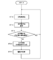
- FIG. 6 is a flowchart relating to generator control.
- FIG. 7 is a flowchart relating to motorized valve control.
- FIG. 8 is a graph showing a specific example of pressure control according to the embodiment. In this example, power running is prohibited.
- FIG. 9 is a graph showing a specific example of pressure control according to the embodiment. In this example, power running is permitted.
- FIG. 10 is a graph showing a specific example of pressure control according to a comparative example.
- FIG. 11 is a schematic configuration diagram of a hydroelectric power generation system and a water supply according to a modified example of the embodiment.
- Embodiment >> The hydroelectric power generation system (10) shown in FIG. 1 is applied to the water supply (1).
- the hydroelectric power generation system (10) of this example is applied to the terminal side of the water supply (1).
- the water (fluid) that flows through the hydroelectric power generation system (10) is supplied to houses and buildings.
- the water supply (1) includes a water distribution tank (2) and a flow path (4).
- the flow path (4) constitutes a pipeline between the water distribution tank (2) and a water supply target such as a house.
- the flow path (4) is a water channel through which water flows with a head.
- the flow path (4) includes a first flow path (5) and a second flow path (6).
- the first flow path (5) is formed on the upstream side of the water turbine (11).
- the first flow path (5) is formed between the water distribution tank (2) and the water turbine (11).
- the second flow path (6) is formed on the downstream side of the water turbine (11).
- the second flow path (6) is formed between the water turbine (11) and the water supply target.
- the hydroelectric power generation system (10) includes a water turbine (11), a generator (12), an electric valve (15), and a pressure sensor (20). As shown in FIG. 2, the hydroelectric power generation system (10) includes a generator controller (30) and a grid interconnection inverter (50).
- the water turbine (11) is arranged in the middle of the flow path (4).
- the water turbine (11) includes a casing and an impeller housed in the casing (not shown).
- a rotating shaft (13) is fixed to the center of the impeller. When the water turbine (11) is rotated by the water flowing through the flow path (4), the rotation shaft (13) is rotationally driven.
- the generator (12) is connected to the turbine (11) via a rotating shaft (13).
- the generator (12) has a rotor and a stator (not shown).
- the rotor is a permanent magnet embedded type.
- the stator has a coil.
- the generator (12) When the water turbine (11) rotates, the generator (12) is driven by the water turbine (11). As a result, the generator (12) performs regenerative operation. The generator (12) during rotary operation generates electric power. The electric power generated by the generator (12) is supplied to the electric power system (60) via the electric power circuit (C).
- the power system (60) is, for example, a commercial power source.
- the power circuit (C) is configured to be able to supply the power of the power system (60) to the generator (12).
- the generator (12) performs a power running operation.
- the generator (12) during power running functions as a motor for rotationally driving the water turbine (11).
- the rotation direction of the water turbine (11) during power running operation is the same as the rotation direction of the water turbine (11) during regenerative operation.
- the motorized valve (15) is arranged in series with the water turbine (11) in the flow path (4).
- the motorized valve (15) is arranged in the first flow path (5).
- the motorized valve (15) is a motor-driven pressure control valve.
- the opening degree of the motorized valve (15) is adjusted by a motor.
- the motorized valve (15) adjusts the effective head (H) of the turbine (11).
- the motorized valve (15) regulates the secondary pressure (P2), which is the pressure on the downstream side of the turbine (11).
- the pressure sensor (20) is arranged in the second flow path (6).
- the pressure sensor (20) is a pressure detection unit that detects the secondary pressure (P2), which is the pressure on the downstream side of the water turbine (11).
- the secondary pressure (P2) detected by the pressure sensor (20) is input to the generator controller (30).
- the power circuit (C) shown in FIG. 2 has an AC / DC converter (31) and a grid interconnection inverter (50).
- the power circuit (C) is configured to be able to supply power in both directions between the generator (12) and the power system.
- the AC / DC converter (31) is provided in the generator controller (30).
- the AC / DC converter (31) includes a plurality of switching elements.
- the AC / DC converter (31) converts the AC power generated by the generator (12) into DC power, and outputs the converted DC power to the grid interconnection inverter (50).
- the AC / DC converter (31) converts the DC power output from the grid interconnection inverter (50) into AC power, and outputs the converted AC power to the generator (12).
- the AC / DC converter (31) is a bidirectional converter.
- the grid interconnection inverter (50) has a plurality of switching elements constituting the inverter unit.
- the grid interconnection inverter (50) converts the DC power output from the AC / DC converter (31) into AC power, and supplies the converted AC power to the power system (60).
- the grid interconnection inverter (50) converts the AC power supplied from the power system into DC power, and outputs the converted DC power to the AC / DC converter (31).
- the grid interconnection inverter (50) has a bidirectional inverter.
- the generator controller (30) shown in FIG. 2 constitutes a control unit that controls the generator (12) and the motorized valve (15).
- the generator controller (30) includes the above-mentioned AC / DC converter (31), a rotation speed detection unit (32), a turbine operating point estimation unit (33), a pressure detection unit (34), and a pressure control unit ( It has a 35), a generator control unit (36), and a valve control unit (37).
- the generator controller (30) includes a microcomputer and a memory device in which a program for operating the microcomputer is stored.
- the rotation speed detection unit (32) detects the rotation speed of the generator (12).
- the rotation speed detected by the rotation speed detection unit (32) is output to the water turbine operating point estimation unit (33) and the generator control unit (36).
- the water turbine operating point estimation unit (33) obtains the water turbine operating point based on the rotation speed of the generator (12) and the torque command value of the generator (12).
- the secondary pressure (P2) detected by the pressure sensor (20) is input to the pressure detection unit (34).
- the pressure control unit (35) generates the torque command value of the generator (12) based on the preset target pressure (Po) and the secondary pressure (P2).
- the torque command value corresponds to the torque of the generator (12) for converging the secondary pressure (P2) to the target pressure (Po).
- the pressure control unit (35) outputs the generated torque command value to the generator control unit (36).
- the pressure control unit (35) generates an opening command value for the motorized valve (15).
- the opening command value corresponds to the opening of the motorized valve (15) for converging the operating point of the turbine to the normal operating region.
- the pressure control unit (35) outputs the generated opening command value to the valve control unit (37).
- the generator control unit (36) controls the torque of the generator (12) so that the secondary pressure (P2) converges to the target pressure (Po).
- the torque command value output from the pressure control unit (35) and the rotation speed output from the rotation speed detection unit (32) are input to the generator control unit (36).
- the generator control unit (36) calculates the voltage command value according to the input torque command value and the rotation speed.
- the generator control unit (36) controls the switching element of the AC / DC converter (31) based on the voltage command value. As a result, the torque of the generator (12) converges to the torque command value.
- the torque command value includes a negative torque command value for regenerative operation of the generator (12) and a positive torque command value for power running the generator (12).
- the valve control unit (37) controls the opening degree of the motorized valve (15) so that the secondary pressure (P2) converges to the target pressure (Po).
- the opening command value output from the pressure control unit (35) is input to the valve control unit (37).
- the valve control unit (37) outputs a predetermined control signal to the motorized valve (15) according to the input opening command value. As a result, the opening degree of the motorized valve (15) converges to the opening degree command value.
- FIG. 3 is a graph showing the characteristics of the water turbine, which is a so-called characteristic map.
- the vertical axis of FIG. 3 is the effective head (H) of the water turbine (11), and the horizontal axis is the flow rate (Q) flowing through the water turbine (11).
- the effective head (H) is a value obtained by subtracting the head corresponding to the flow path resistance, the pressure loss of the motorized valve (15), and the secondary pressure (P2) from the total head (Ho) shown in FIG.
- the total head (Ho) is the head from the liquid level of the water distribution tank (2) to the outflow end of the flow path (4).
- the flow path resistance corresponds to the resistance of the pipeline of the flow path (4).
- the relationship between the effective head (H) and the flow rate (Q) of the turbine (11) can be represented by the system loss curve (flow resistance characteristic line) shown in FIG.
- the system loss curve has a characteristic that the effective head (H) decreases as the flow rate (Q) increases.
- the point (water turbine operating point) corresponding to the flow rate (Q) and effective head (H) of the turbine (11) always moves on the system loss curve.
- FIG. 3 shows an equal torque curve and an equal rotation speed curve.
- the equal torque curve is a curve representing the torque (T) of the generator (12) and extends vertically.
- a curve in which the torque (T) is 0 is called an unrestrained curve (RC).
- the constant rotation speed curve is a curve representing the rotation speed (N) of the water turbine (11) and extends to the left and right.
- a curve in which the rotation speed (N) is 0 or a predetermined minimum rotation speed is called a turbine limit curve (LC).
- the region between the unrestrained curve (RC) and the turbine limit curve (LC) is the turbine region.
- the generator (12) performs regenerative operation. Negative torque increases as it travels to the right from the unrestrained curve (RC). The number of revolutions (N) increases as the turbine moves upward from the turbine limit curve (LC). Therefore, in the generator (12), the generated power tends to increase as it proceeds in the upper right direction of FIG.
- the area on the left side of the unrestrained curve (RC) is called the turbine brake area.
- the generator (12) performs power running.
- the positive torque increases as it travels to the left from the unrestrained curve (RC).
- FIG. 3 shows the cavitation curve (CC).
- the cavitation curve (CC) is a curve located inside the turbine limit curve (LC) so as to follow the turbine limit curve (LC). Cavitation can occur in the turbine (11) if there is a turbine operating point in the area between the unrestrained curve (RC) and the cavitation curve (CC). On the other hand, when the turbine operating point is in the region (normal operating region) between the cavitation curve (CC) and the turbine limit curve (LC), cavitation does not occur and normal operation can be performed.
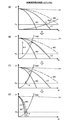
- FIG. 4 is a graph showing the characteristics of the primary pressure (P1), the secondary pressure (P2), and the motorized valve (15) in the hydroelectric power generation system (10) of the present embodiment.
- the vertical axis of FIG. 4 is the pressure of the fluid, and the horizontal axis is the flow rate (Q) of the water turbine (11).
- the primary pressure (P1) in FIG. 4 indicates the pressure on the upstream side of the turbine (11) and the motorized valve (15).
- the motor-operated valve curve (MC) shown in FIG. 4 is a curve showing the relationship between the pressure after depressurization by the motor-operated valve (15) at a predetermined opening degree and the flow rate (Q). Therefore, for example, the difference between the primary pressure (P1) and the motor-operated valve curve (MC) at the flow rate (Q) corresponding to the water turbine operating point (white points shown in FIG. 4) is the amount of decompression by the motor-operated valve (15). is there.
- the motorized valve curve (MC) becomes a gentle curve along the primary pressure (P1) as the opening degree increases.
- the motorized valve curve (MC) becomes a steeper curve along the unrestrained curve (RC) as the opening degree becomes smaller.
- the secondary characteristic curve (P2C) is a curve showing the relationship between the pressure loss and the flow rate on the downstream side of the turbine (11).
- the quadratic characteristic curve (P2C) can be said to be a curve connecting the difference between the pressure of the solenoid valve curve (MC) and the effective head (H) of the system loss curve at the same flow rate (Q). Therefore, the turbine operating point is always on the secondary characteristic curve (P2C).
- the quadratic characteristic curve (P2C) becomes a gentle curve that sleeps in the lower right as the flow rate (Q) increases.
- the quadratic characteristic curve (P2C) becomes a steep curve that rises to the upper left as the flow rate (Q) decreases.
- the difference between the motorized valve curve (MC) and the secondary characteristic curve (P2C) is the amount of decompression by the turbine (11).
- FIG. 4 shows the above-mentioned unrestrained curve (RC), turbine limit curve (LC), and cavitation curve (CC).
- the area indicated by the hatching on the left side of the unrestrained curve (RC) is the above-mentioned turbine braking area (power running area).
- the area between the turbine limit curve (LC) and the cavitation curve (CC) is the normal operating area.
- the turbine limit curve (LC) becomes a gentle curve along the primary pressure (P1) as the opening degree of the motorized valve (15) increases.
- the turbine limit curve (LC) becomes a steeper curve that follows the unrestrained curve (RC) as the opening degree of the motorized valve (15) becomes smaller.
- the unrestrained curve (RC) becomes a gentle curve as the opening degree of the motorized valve (15) increases, and becomes a steeper curve as the opening degree of the motorized valve (15) decreases.
- the relationship between the parameters shown in FIGS. 3 and 4 is stored in the memory device of the generator controller (30) as data such as tables and functions. Therefore, the generator controller (30) can obtain various indexes by using this data.
- the water in the water distribution tank (2) flows through the flow path (4).
- the water in the flow path (4) passes through the motorized valve (15) and then flows through the water turbine (11).
- electricity is generated from the generator (12).
- the generator (12) in this state is performing regenerative operation.
- the AC power generated by the generator (12) is converted to DC power by the AC / DC converter (31).
- the DC power converted by the AC / DC converter (31) is converted into AC power by the grid interconnection inverter (50) and supplied to the power grid (60).
- a control for lowering the secondary pressure (P2) As a control for lowering the secondary pressure (P2), as shown in FIG. 4, a control (electric valve control) in which the electric valve (15) is controlled and the amount of decompression by the electric valve (15) is adjusted, and a generator (electric valve control) There is a control (generator control) that controls 12) and adjusts the amount of decompression by the water turbine (11).
- the responsiveness of pressure regulation by the motorized valve (15) is extremely lower than the responsiveness of pressure regulation by the generator (12), and there is a problem that the secondary pressure (P2) cannot be reduced quickly. Specifically, since the motorized valve (15) is driven by a motor, its responsiveness is low. In addition, the motorized valve (15) has a characteristic that a sufficient amount of decompression cannot be obtained unless the opening degree is relatively small. This characteristic contributes to a decrease in the responsiveness of pressure regulation by the motorized valve (15).
- FIG. 5 is a graph showing an example of the relationship between the opening degree (%) of the solenoid valve and the loss coefficient.
- the loss factor is an index showing the amount of decompression of the motorized valve. According to the characteristics of the motorized valve shown in FIG. 5, the loss coefficient sharply increases when the opening degree is about 20% or less. In other words, the motorized valve cannot obtain a sufficient decompression amount unless its opening degree is about 20% or less. Therefore, in the solenoid valve control, when the secondary pressure (P2) suddenly rises, there is a concern that the secondary pressure (P2) cannot be quickly converged to the target pressure (Po).
- FIG. 10 is a graph corresponding to FIG. FIG. 10 shows the primary pressure (P1), the solenoid valve curve (Mc), the secondary side characteristic curve (P2C), the turbine limit curve (LC), and the unrestrained curve (RC). Although not shown, the cavitation curve (CC) is slightly inside the turbine limit curve (LC), as in FIG.
- the operating point of the turbine at position a is located on the intersection of the secondary characteristic curve (P2C) and the target pressure (Po). Therefore, the secondary pressure (P2) is maintained at the target pressure (Po). From this state, for example, when the amount of water consumed in a house or the like is almost eliminated and the secondary pressure (P2) rises sharply, the operating point of the turbine moves from a to b as shown in FIG. 10 (B).
- the opening of the motorized valve (15) gradually decreases, although it lags behind the control of the generator (12).
- the operating point of the turbine moves from f to g, and the secondary pressure (P2) converges to the target pressure (Po).
- the operating point of the water turbine is from FIG. 10C to FIG. 10D, it takes, for example, about 20 to 30 seconds to converge the opening degree of the electric valve (15) to the target opening degree. Therefore, even in the pressure control of the comparative example, there was a concern that the requirement of the water supply (1) could not be satisfied due to the delay in the response of the motorized valve (15).
- FIG. 6 is a flowchart relating to the generator control of the present embodiment.
- the pressure sensor (20) detects the secondary pressure (P2).
- the pressure deviation ( ⁇ P) and the threshold (Ps) are compared.
- step ST3 a flag that allows power running is established.
- the lower limit of the secondary pressure (P2) adjustment range can be expanded.
- the secondary pressure (P2) can be converged to the target pressure (Po) even when the pressure deviation ( ⁇ P) is larger than the threshold value (Ps).
- step ST4 a flag prohibiting power running is established.
- the pressure deviation ( ⁇ P) is equal to or less than the threshold value (Ps)
- the secondary pressure (P2) can be converged to the target pressure (Po) only by the regenerative operation.
- step ST5 the pressure control unit (35) generates a torque command value.
- the torque command value corresponds to the torque of the generator (12) for converging the secondary pressure (P2) to the target pressure (Po).
- step ST5 when the flag for permitting power running operation is established, the torque command value is generated in the range from the predetermined positive torque value in FIG. 3 to the predetermined negative torque value.
- the torque command value includes not only the region in which the generator (12) performs regenerative operation (water turbine region) but also the region in which the generator (12) performs power running operation (water turbine braking region or power running region).
- step ST5 when the flag for permitting power running is established in step ST5, it is preferable to set the upper limit value to the positive torque command value so that the operating point of the turbine does not reach the reverse pump region.
- the reversing pump region is an region in which the flow rate (Q) becomes negative as the turbine (11) rotates due to the excessively large positive torque when the generator (12) performs power running operation. ..
- the operating point of the turbine reaches the reverse pump region, water flows backward in the forward direction of the water flow of the turbine (11). Therefore, in the second control in which the power running operation is permitted, it is preferable to control the generator (12) so that the fluid flows in the forward direction of the water turbine (11) while performing the power running operation.
- the "forward direction” here is the direction in which water flows from the upstream side to the downstream side in the flow path (4) in the normal state.
- step ST5 When the torque command value is generated in step ST5, the process proceeds to step ST6.
- step ST6 the torque of the generator (12) converges to the torque command value, and the secondary pressure (P2) converges to the target pressure (Po).
- FIG. 7 is a flowchart relating to the motorized valve control of the present embodiment.
- the rotation speed detection unit (32) detects the rotation speed of the generator (12).
- the turbine operating point estimation unit (33) estimates the current turbine operating point.
- the water turbine operating point estimation unit (33) obtains the water turbine operating point from the rotation speed (N) and torque (T) of the generator (12) based on, for example, the data related to the characteristic map shown in FIG. As an index corresponding to the torque (T), the torque command value generated by the pressure control unit (35) is used.
- the turbine operating point estimation unit (33) may obtain the turbine operating point by, for example, measuring the flow rate (Q) of the turbine (11) or measuring the electric power generated by the generator (12). it can.
- step ST12 it is determined whether or not the turbine operating point obtained in step ST11 is in the normal operating area. This determination is made by the pressure control unit (35).
- the normal operating region is the region between the cavitation curve (CC) and the turbine limit curve (LC), as described above. If it is determined in step ST12 that the turbine operating point is in the normal operating range, the pressure control by the motorized valve (15) is not executed.
- step ST12 if it is determined that the turbine operating point is not in the normal operating area, the process proceeds to step ST13.
- the pressure control unit (35) generates an opening command value.
- the opening command value corresponds to the opening of the motorized valve (15) for converging the turbine operating point to the normal operating region.
- step ST13 When the opening command value is generated in step ST13, the process proceeds to step ST14.
- step ST14 the opening degree of the motorized valve (15) converges to the opening degree command value.
- FIG. 8 is a control example when pressure control by power running operation is prohibited.
- the responsiveness of pressure regulation by the generator (12) is higher than the responsiveness of pressure regulation by the motorized valve (15). Therefore, when the generator control is executed, the negative torque quickly decreases and the secondary pressure (P2) decreases. As shown in FIG. 8C, when the turbine operating point reaches the position c, the secondary pressure (P2) converges to the target pressure (Po). In this example, the pressure deviation ( ⁇ P) is relatively small. Therefore, the secondary pressure (P2) can be converged to the target pressure (Po) in the water turbine region where the rotary operation is performed.
- step ST12 of FIG. 7 it is determined that the turbine operating point is not in the normal operating area, and the process proceeds to step ST13.
- the opening degree of the motor-operated valve (15) becomes smaller, and the amount of decompression of the electric valve (15) becomes larger.
- the electric valve curve (MC), the turbine limit curve (LC), and the unrestrained curve (RC) become steep curves, and the turbine operating point approaches the turbine limit curve (LC).
- FIG. 9 is a control example when pressure control by power running is permitted.
- the responsiveness of pressure regulation by the generator (12) is higher than the responsiveness of pressure regulation by the motorized valve (15). Therefore, when the generator control is executed, the negative torque quickly decreases and the secondary pressure (P2) decreases.
- the pressure deviation ( ⁇ P) is relatively large. Therefore, the secondary pressure (P2) cannot be converged to the target pressure (Po) only in the turbine region where the rotary operation is performed. In this case, the positive torque increases in the power running region, and the secondary pressure (P2) further decreases.
- the operating point of the turbine moves to the position d, and the secondary pressure (P2) converges to the target pressure (Po).
- the turbine operating point at position d is in the power running region.
- the secondary pressure (P2) is lowered by utilizing the power running region under the condition that the pressure deviation ( ⁇ P) is relatively large.
- the relatively high secondary pressure (P2) can be quickly converged to the target pressure (Po), and the water supply (1) can be satisfied.
- step ST12 of FIG. 7 it is determined that the turbine operating point is not in the normal operating area, and the process proceeds to step ST13.
- the opening degree of the motor-operated valve (15) becomes smaller, and the amount of decompression of the electric valve (15) becomes larger.
- the electric valve curve (MC), the turbine limit curve (LC), and the unrestrained curve (RC) become steep curves, and the turbine operating point approaches the turbine limit curve (LC).
- a water wheel (11) arranged in a flow path (4) through which a fluid flows, a generator (12) connected to the water wheel (11), and a fluid pressure (secondary) on the downstream side of the water wheel (11). It is equipped with a control unit (30) that controls the generator (12) so as to adjust the pressure (P2)), and the pressure control adjusts the pressure while regenerating the generator (12). It includes a first control and a second control that adjusts the pressure while driving the generator (12).
- the embodiment includes an electric valve (15) arranged in series with the water turbine (11) in the flow path (4).
- the range of pressure adjustment of the secondary pressure (P2) can be expanded by adjusting the opening degree of the motorized valve (15) in addition to controlling the generator (12).
- control unit (30) controls the generator (12) so that the secondary pressure (P2) approaches the target pressure (Po) in the pressure control.
- control unit (30) controls the motorized valve (15) so that the operating point of the turbine is converged to the normal operating region in the pressure control.
- the opening of the motorized valve (15) is adjusted when the operating point of the turbine deviates from the normal operating range. Therefore, the secondary pressure (P2) can be quickly converged to the target pressure (Po), and the occurrence of cavitation can be suppressed.
- the responsiveness of the pressure adjustment by the generator (12) is higher than the responsiveness of the pressure adjustment by the electric valve (15). Therefore, first, the secondary pressure (P2) can be quickly and surely converged to the target pressure (Po) by controlling the generator with high responsiveness and a wide pressure adjustment range.
- the low responsive motorized valve (15) can complementarily adjust the secondary pressure (P2) and suppress the occurrence of cavitation.
- the second control for power running is permitted. Therefore, under the condition that the secondary pressure (P2) is relatively high, the secondary pressure (P2) can be quickly converged to the target pressure (Po).
- the second control for power running is prohibited. Therefore, under the condition that the secondary pressure (P2) is relatively small, the secondary pressure (P2) can be converged to the target pressure (Po) only by the regenerative operation. In this case, the power generation of the generator (12) can be continued.
- the modified example hydroelectric power generation system (10) shown in FIG. 11 includes a bypass flow path (8) and a pressure reducing valve (16).
- the bypass flow path (8) is a flow path that bypasses the motorized valve (15) and the water turbine (11).
- the inflow end of the bypass flow path (8) is connected to the upstream side of the motorized valve (15) in the first flow path (5).
- the outflow end of the bypass flow path (8) is connected to the upstream side of the pressure sensor (20) in the second flow path (6).
- the pressure reducing valve (16) is arranged in the bypass flow path (8).
- the opening degree of the pressure reducing valve (16) is adjusted so that the pressure (secondary pressure (P2)) on the downstream side of the water turbine (11) becomes a predetermined value.
- the pressure reducing valve (16) is mechanically released by a spring or the like to increase the secondary pressure (P2).
- the first value is set lower than the target pressure (Po) of the secondary pressure (P2). Therefore, in normal operation in which the secondary pressure (P2) is maintained at the target pressure (Po), the pressure reducing valve (16) is not opened.
- the secondary pressure (P2) on the downstream side of the turbine (11) may drop sharply. Also in this case, by opening the pressure reducing valve (16), it is possible to suppress a sudden drop in the secondary pressure (P2).
- the flow path (4) through which the fluid flows does not have to be a pipeline, and may be a groove with an open upper side.
- the flow path (4) may be applied to other than the water supply (1).
- the flow path (4) may not be provided with a water distribution tank (2), and a water storage tank may be provided instead of the water distribution tank (2).
- the fluid does not necessarily have to be water, and may be, for example, brine used in an air conditioner.
- the secondary pressure (P2) is adjusted by controlling the torque of the generator (12).
- the secondary pressure (P2) may be adjusted by controlling the rotation speed of the generator (12).
- the first control for adjusting the secondary pressure (P2) while performing the regenerative operation and the second control for adjusting the secondary pressure (P2) while performing the power running operation can be executed.
- the AC / DC converter (31) may be configured by a matrix converter or a cycloconverter.
- the AC / DC converter (31) may be provided separately from the generator controller (30).
- a rechargeable battery may be used instead of the commercial power supply that is the power system (60).
- the electric power generated by the generator (12) that performs regenerative operation is stored in the rechargeable battery.
- the generator (12) performs power running operation.
- This disclosure is useful as a hydroelectric power generation system.
Landscapes
- Engineering & Computer Science (AREA)
- Chemical & Material Sciences (AREA)
- Combustion & Propulsion (AREA)
- Mechanical Engineering (AREA)
- General Engineering & Computer Science (AREA)
- Control Of Water Turbines (AREA)
- Control Of Eletrric Generators (AREA)
Abstract
水力発電システム(10)は、水車(11)の下流側の流体の圧力を調節するように発電機(12)を制御する圧力制御を行う制御部(30)とを備える。圧力制御は、発電機(12)を回生運転させながら圧力を調節する第1制御と、発電機(12)を力行運転させながら圧力を調節する第2制御とを含んでいる。
Description
本開示は、水力発電システムに関する。
特許文献1に開示された水力発電システムは、流路に配置される水車と、水車と連結する発電機とを備える。水車は、流路を流れる流体によって回転される。水車が回転すると、発電機が駆動される。駆動された発電機は、電力を発生する。
水力発電システムにおいて、水車の下流側の圧力を調節することが想定される。具体的には、回生運転中の発電機のトルクや回転数を制御することで、水車の下流側の圧力を調節できる。しかし、この制御だけでは、調節される圧力の調整範囲に限界があった。
本開示は、水車の下流側の圧力の調節範囲を拡大することである。
第1の態様は、流体が流れる流路(4)に配置される水車(11)と、前記水車(11)と連結する発電機(12)と、前記水車(11)の下流側の流体の圧力を調節するように前記発電機(12)を制御する圧力制御を行う制御部(30)とを備え、前記圧力制御は、前記発電機(12)を回生運転させながら前記圧力を調節する第1制御と、前記発電機(12)を力行運転させながら前記圧力を調節する第2制御とを含んでいることを特徴とする水力発電システムである。
第1の態様の圧力制御は、発電機(12)を力行運転させる第2制御を含む。発電機(12)を力行運転させると、水車(11)の下流側の圧力を、第1制御よりも低い範囲で調節できる。これにより、圧力制御における圧力の調節範囲が拡大する。
第2の態様は、第1の態様において、前記制御部(30)は、前記圧力制御において、前記水車(11)の下流側の流体の圧力が目標圧力に収束するように前記発電機(12)を制御する。
第2の態様では、水車(11)の圧力の調節の範囲が拡大することで、水車(11)の下流側の圧力を目標圧力に収束させ易くなる。
第3の態様は、第1又は第2の態様において、前記流路(4)に前記水車(11)と直列に配置される電動弁(15)を備えていることを特徴とする水力発電システムである。
第3の態様では、電動弁(15)の開度を調節することで、圧力制御における圧力の調節範囲がさらに拡大する。
第4の態様は、第3の態様において、前記制御部(30)は、前記圧力制御において、前記水車(11)の動作点を正常の運転領域に収束させるように前記電動弁(15)を制御することを特徴とする水力発電システムである。
第4の態様では、水車(11)の動作点が正常の運転領域から外れてしまうことを、電動弁(15)の制御により抑制できる。
第5の態様は、第3又は第4の態様において、前記発電機(12)による圧力調節の応答性が、前記電動弁(15)による圧力調節の応答性よりも高いことを特徴とする水力発電システムである。
第5の態様では、発電機(12)の制御により、水車(11)の下流側の圧力を速やかに目標圧力に収束させることができる。加えて第2制御により、広い範囲での圧力の調節が可能となる。
第6の態様は、第3乃至5の態様のいずれか1つにおいて、前記水車(11)及び電動弁(15)をバイパスするバイパス流路(8)と、前記バイパス流路(8)に配置され、前記圧力が所定値となるように開度を調整する減圧弁(16)とを備えていることを特徴とする水力発電システムである。
第6の態様では、停電などにより電動弁(15)が閉じてしまった場合や、水車(11)の下流側の流体の流量が急激に増大した場合に、水車(11)の下流側の圧力が低下する。これに伴い減圧弁(16)の開度が大きくなることで、流体はバイパス流路(8)を経由して下流側へ供給される。これにより、水車(11)の下流側の圧力を抑制できる。
以下、本発明の実施形態について図面を参照しながら説明する。なお、以下の実施形態は、本質的に好ましい例示であって、本発明、その適用物、あるいはその用途の範囲を制限することを意図するものではない。
《実施形態》
図1に示す水力発電システム(10)は、上水道(1)に適用される。本例の水力発電システム(10)は、上水道(1)の末端側に適用される。水力発電システム(10)を流れた水(流体)は、住宅・ビルなどに供給される。
図1に示す水力発電システム(10)は、上水道(1)に適用される。本例の水力発電システム(10)は、上水道(1)の末端側に適用される。水力発電システム(10)を流れた水(流体)は、住宅・ビルなどに供給される。
〈上水道〉
上水道(1)は、配水槽(2)と流路(4)とを含む。流路(4)は、配水槽(2)と、住宅などの水の供給対象との間の管路を構成している。流路(4)は、落差を有して水が流れる水路である。
上水道(1)は、配水槽(2)と流路(4)とを含む。流路(4)は、配水槽(2)と、住宅などの水の供給対象との間の管路を構成している。流路(4)は、落差を有して水が流れる水路である。
流路(4)は、第1流路(5)と第2流路(6)とを含む。第1流路(5)は、水車(11)の上流側に形成される。第1流路(5)は、配水槽(2)と水車(11)との間に形成される。第2流路(6)は、水車(11)の下流側に形成される。第2流路(6)は、水車(11)と水の供給対象との間に形成される。
〈水力発電システム〉
図1及び図2に示すように、水力発電システム(10)は、水車(11)と、発電機(12)と、電動弁(15)と、圧力センサ(20)とを備える。図2に示すように、水力発電システム(10)は、発電機コントローラ(30)と、系統連系インバータ(50)とを備える。
図1及び図2に示すように、水力発電システム(10)は、水車(11)と、発電機(12)と、電動弁(15)と、圧力センサ(20)とを備える。図2に示すように、水力発電システム(10)は、発電機コントローラ(30)と、系統連系インバータ(50)とを備える。
〈水車〉
水車(11)は、流路(4)の途中に配置される。水車(11)は、ケーシングと、ケーシングに収容される羽根車とを備える(図示省略)。羽根車の中心部には、回転軸(13)が固定される。流路(4)を流れる水によって水車(11)が回転すると、回転軸(13)が回転駆動される。
水車(11)は、流路(4)の途中に配置される。水車(11)は、ケーシングと、ケーシングに収容される羽根車とを備える(図示省略)。羽根車の中心部には、回転軸(13)が固定される。流路(4)を流れる水によって水車(11)が回転すると、回転軸(13)が回転駆動される。
〈発電機〉
発電機(12)は、回転軸(13)を介して水車(11)と連結する。発電機(12)は、ロータとステータとを有する(図示省略)。ロータは、永久磁石埋込型である。ステータはコイルを有する。
発電機(12)は、回転軸(13)を介して水車(11)と連結する。発電機(12)は、ロータとステータとを有する(図示省略)。ロータは、永久磁石埋込型である。ステータはコイルを有する。
水車(11)が回転すると、水車(11)によって発電機(12)が駆動される。これにより、発電機(12)が回生運転を行う。回転運転中の発電機(12)は、電力を発生する。発電機(12)が発生した電力は、電力回路(C)を介して電力系統(60)へ供給される。電力系統(60)は、例えば商用電源である。
詳細は後述するが、電力回路(C)は、電力系統(60)の電力を発電機(12)に供給可能に構成される。電力系統(60)の電力が電力回路(C)を介して発電機(12)に供給されると、発電機(12)は力行運転を行う。力行運転中の発電機(12)は、水車(11)を回転駆動するモータとして機能する。なお、本実施形態では、力行運転時の水車(11)の回転方向と、回生運転時の水車(11)の回転方向は同じである。
〈電動弁〉
電動弁(15)は、流路(4)に水車(11)と直列に配置される。電動弁(15)は、第1流路(5)に配置される。電動弁(15)は、モータ駆動式の圧力調節弁である。電動弁(15)は、モータによって開度が調節される。電動弁(15)は、水車(11)の有効落差(H)を調節する。加えて、電動弁(15)は、水車(11)の下流側の圧力である二次圧(P2)を調節する。
電動弁(15)は、流路(4)に水車(11)と直列に配置される。電動弁(15)は、第1流路(5)に配置される。電動弁(15)は、モータ駆動式の圧力調節弁である。電動弁(15)は、モータによって開度が調節される。電動弁(15)は、水車(11)の有効落差(H)を調節する。加えて、電動弁(15)は、水車(11)の下流側の圧力である二次圧(P2)を調節する。
〈圧力センサ〉
圧力センサ(20)は、第2流路(6)に配置される。圧力センサ(20)は、水車(11)の下流側の圧力である二次圧(P2)を検出する圧力検知部である。圧力センサ(20)によって検出された二次圧(P2)は、発電機コントローラ(30)に入力される。
圧力センサ(20)は、第2流路(6)に配置される。圧力センサ(20)は、水車(11)の下流側の圧力である二次圧(P2)を検出する圧力検知部である。圧力センサ(20)によって検出された二次圧(P2)は、発電機コントローラ(30)に入力される。
〈電力回路〉
図2に示す電力回路(C)は、AC/DCコンバータ(31)と、系統連系インバータ(50)とを有する。電力回路(C)は、発電機(12)と電力系統の間で双方向に電力を供給可能に構成される。
図2に示す電力回路(C)は、AC/DCコンバータ(31)と、系統連系インバータ(50)とを有する。電力回路(C)は、発電機(12)と電力系統の間で双方向に電力を供給可能に構成される。
AC/DCコンバータ(31)は、発電機コントローラ(30)に設けられる。AC/DCコンバータ(31)は、複数のスイッチング素子を備える。AC/DCコンバータ(31)は、発電機(12)が発電した交流電力を直流電力に変換し、変換した直流電力を系統連系インバータ(50)に出力する。AC/DCコンバータ(31)は、系統連系インバータ(50)から出力された直流電力を交流電力に変換し、変換した交流電力を発電機(12)に出力する。このように、AC/DCコンバータ(31)は、双方向式のコンバータである。
系統連系インバータ(50)は、インバータ部を構成する複数のスイッチング素子を有する。系統連系インバータ(50)は、AC/DCコンバータ(31)から出力された直流電力を交流電力に変換し、変換した交流電力を電力系統(60)に供給する。系統連系インバータ(50)は、電力系統から供給された交流電力を直流電力に変換し、変換した直流電力をAC/DCコンバータ(31)に出力する。このように、系統連系インバータ(50)は、双方向式のインバータを有する。
〈発電機コントローラ〉
図2に示す発電機コントローラ(30)は、発電機(12)及び電動弁(15)を制御する制御部を構成している。発電機コントローラ(30)は、上述したAC/DCコンバータ(31)と、回転数検出部(32)と、水車動作点推定部(33)と、圧力検出部(34)と、圧力制御部(35)と、発電機制御部(36)と、弁制御部(37)とを有する。発電機コントローラ(30)は、マイクロコンピュータと、それを動作させるためのプログラムが格納されたメモリディバイスとを含む。
図2に示す発電機コントローラ(30)は、発電機(12)及び電動弁(15)を制御する制御部を構成している。発電機コントローラ(30)は、上述したAC/DCコンバータ(31)と、回転数検出部(32)と、水車動作点推定部(33)と、圧力検出部(34)と、圧力制御部(35)と、発電機制御部(36)と、弁制御部(37)とを有する。発電機コントローラ(30)は、マイクロコンピュータと、それを動作させるためのプログラムが格納されたメモリディバイスとを含む。
回転数検出部(32)は、発電機(12)の回転数を検出する。回転数検出部(32)で検出した回転数は、水車動作点推定部(33)及び発電機制御部(36)に出力される。水車動作点推定部(33)は、発電機(12)の回転数、及び発電機(12)のトルク指令値とに基づいて水車動作点を求める。圧力検出部(34)は、圧力センサ(20)で検出した二次圧(P2)が入力される。
圧力制御部(35)は、予め設定された目標圧力(Po)と、二次圧(P2)とに基づいて発電機(12)のトルク指令値を生成する。トルク指令値は、二次圧(P2)を目標圧力(Po)に収束させるための発電機(12)のトルクに相当する。圧力制御部(35)は、生成したトルク指令値を発電機制御部(36)に出力する。
加えて、圧力制御部(35)は、電動弁(15)の開度指令値を生成する。開度指令値は、水車動作点を通常の運転領域に収束させるための電動弁(15)の開度に相当する。圧力制御部(35)は、生成した開度指令値を弁制御部(37)に出力する。
発電機制御部(36)は、二次圧(P2)が目標圧力(Po)に収束するように発電機(12)のトルクを制御する。発電機制御部(36)には、圧力制御部(35)から出力されたトルク指令値と、回転数検出部(32)から出力された回転数とが入力される。発電機制御部(36)は、入力されたトルク指令値及び回転数に従って電圧指令値を算出する。発電機制御部(36)は、電圧指令値に基づいてAC/DCコンバータ(31)のスイッチング素子を制御する。これにより、発電機(12)のトルクがトルク指令値に収束する。ここで、トルク指令値は、発電機(12)を回生運転させる負のトルク指令値と、発電機(12)を力行運転させる正のトルク指令値とを含む。
弁制御部(37)は、二次圧(P2)が目標圧力(Po)に収束するように電動弁(15)の開度を制御する。弁制御部(37)には、圧力制御部(35)から出力された開度指令値が入力される。弁制御部(37)は、入力された開度指令値に従って所定の制御信号を電動弁(15)に出力する。これにより、電動弁(15)の開度が開度指令値に収束する。
〈水力発電システム及び流路の特性〉
水力発電システム(10)及び流路(4)の特性について、図3及び図4を参照しながら説明する。
水力発電システム(10)及び流路(4)の特性について、図3及び図4を参照しながら説明する。
図3は、水車の特性を示すグラフであり、いわゆる特性マップである。図3の縦軸は、水車(11)の有効落差(H)、横軸は水車(11)を流れる流量(Q)である。有効落差(H)は、図1に示す総落差(Ho)から、流路抵抗に相当する落差、電動弁(15)の圧力損失、及び二次圧(P2)を引いた値である。総落差(Ho)は、配水槽(2)の液面から流路(4)の流出端まで間の落差である。流路抵抗は、流路(4)の管路の抵抗に相当する。
水車(11)の有効落差(H)及び流量(Q)の関係は、図3に示すシステムロスカーブ(流動抵抗特性線)で表すことができる。システムロスカーブは、流量(Q)の増大に伴って有効落差(H)が減少する特性を有する。水車(11)の流量(Q)と有効落差(H)に対応する点(水車動作点)は、常にシステムロスカーブ上を移動する。
図3は、等トルク曲線及び等回転数曲線を表している。等トルク曲線は、発電機(12)のトルク(T)を表す曲線であり、上下に延びている。トルク(T)が0となる曲線を無拘束曲線(RC)という。等回転数曲線は、水車(11)の回転数(N)を表す曲線であり、左右に延びている。回転数(N)が0又は所定の最低回転数となる曲線を水車限界曲線(LC)という。
無拘束曲線(RC)と水車限界曲線(LC)の間の領域は、水車領域である。水車領域に水車動作点があるとき、発電機(12)は回生運転を行う。無拘束曲線(RC)から右方向に進むにつれて負のトルクが増大する。水車限界曲線(LC)から上方向にすすむにつれて回転数(N)が増大する。従って、発電機(12)では、図3の右上方向にすすむにつれて発電電力が増大する傾向にある。
無拘束曲線(RC)の左側の領域は、水車ブレーキ領域という。水車ブレーキ領域に水車動作点があるとき、発電機(12)は力行運転を行う。無拘束曲線(RC)から左方向に進むにつれて正のトルクが増大する。
図3は、キャビテーション曲線(CC)を表している。キャビテーション曲線(CC)は、水車限界曲線(LC)に沿うように該水車限界曲線(LC)の内側に位置する曲線である。無拘束曲線(RC)とキャビテーション曲線(CC)との間の領域に水車動作点がある場合、水車(11)においてキャビテーションが発生する可能性がある。一方、キャビテーション曲線(CC)と水車限界曲線(LC)との間の領域(通常の運転領域)に水車動作点がある場合、キャビテーションは発生せず、通常の運転を行うことができる。
図4は、本実施形態の水力発電システム(10)における一次圧(P1)、二次圧(P2)、電動弁(15)の特性を表したグラフである。図4の縦軸は流体の圧力、横軸は水車(11)の流量(Q)である。
図4の一次圧(P1)は、水車(11)及び電動弁(15)の上流側の圧力を示す。図4に示す電動弁曲線(MC)は、所定の開度での電動弁(15)による減圧後の圧力と流量(Q)との関係を表した曲線である。よって、例えば水車動作点(図4に示す白抜きの点)に対応する流量(Q)における一次圧(P1)と電動弁曲線(MC)との差が、電動弁(15)による減圧量である。電動弁曲線(MC)は、その開度が大きくなるほど一次圧(P1)に沿うように緩やかな曲線となる。電動弁曲線(MC)は、その開度が小さくなるほど無拘束曲線(RC)に沿うように急峻な曲線となる。
二次側特性曲線(P2C)は、水車(11)の下流側の圧力損失と流量の関係を表した曲線である。二次側特性曲線(P2C)は、同じ流量(Q)における、電動弁曲線(MC)の圧力とシステムロスカーブの有効落差(H)の差分を結んだ曲線といえる。従って、水車動作点は、常に二次側特性曲線(P2C)上にある。二次側特性曲線(P2C)は、流量(Q)が大きくなるほど、右下に寝るような緩やかな曲線となる。二次側特性曲線(P2C)は、流量(Q)が小さくなるほど、左上に立ち上がるような急峻な曲線となる。図4に例示する水車動作点に対応する流量(Q)において、電動弁曲線(MC)と二次側特性曲線(P2C)との差が水車(11)による減圧量である。
図4は、上述した無拘束曲線(RC)、水車限界曲線(LC)、及びキャビテーション曲線(CC)を表している。無拘束曲線(RC)の左側のハッチングで示す領域が、上述した水車ブレーキ領域(力行領域)である。水車限界曲線(LC)とキャビテーション曲線(CC)との間の領域が、通常の運転領域である。図4において、水車限界曲線(LC)は、電動弁(15)の開度が大きくなるほど一次圧(P1)に沿うような緩やかな曲線となる。水車限界曲線(LC)は、電動弁(15)の開度が小さくなるほど無拘束曲線(RC)に沿うような急峻な曲線となる。図4において、無拘束曲線(RC)は、電動弁(15)の開度が大きくなるほど緩やかな曲線となり、電動弁(15)の開度が小さくなるほど急峻な曲線となる。
図3や図4に示す各パラメータの関係は、テーブルや関数などのデータとして、発電機コントローラ(30)のメモリディバイスに記憶される。従って、発電機コントローラ(30)は、このデータを利用することで種々の指標を求めることができる。
-運転動作-
水力発電システム(10)の運転動作について説明する。
水力発電システム(10)の運転動作について説明する。
〈基本動作〉
水力発電システム(10)の基本動作について図1及び図2を参照しながら説明する。
水力発電システム(10)の基本動作について図1及び図2を参照しながら説明する。
配水槽(2)の水は、流路(4)を流れる。流路(4)の水は電動弁(15)を通過した後、水車(11)を流れる。水流によって水車(11)が回転すると発電機(12)から電力が発生する。この状態の発電機(12)は回生運転を行っている。
発電機(12)で発生した交流電力は、AC/DCコンバータ(31)で直流電力に変換される。AC/DCコンバータ(31)で変換された直流電力は、系統連系インバータ(50)で交流電力に変換され、電力系統(60)に供給される。
〈圧力制御の課題〉
水力発電システム(10)が適用される流路(4)では、水車(11)の二次圧(P2)を目標圧力(Po)に維持する必要がある。ところが、二次圧(P2)は、流路(4)の下流側の水の消費量に応じて変化する。例えば深夜においては、住宅などの水の消費量はほとんどない。このため、住宅などに供給される流量が減少し、これに伴い二次圧(P2)が急上昇することがある。この結果、二次圧(P2)を目標圧力(Po)に維持できず、上水道(1)の要求を満たすことができないという懸念があった。
水力発電システム(10)が適用される流路(4)では、水車(11)の二次圧(P2)を目標圧力(Po)に維持する必要がある。ところが、二次圧(P2)は、流路(4)の下流側の水の消費量に応じて変化する。例えば深夜においては、住宅などの水の消費量はほとんどない。このため、住宅などに供給される流量が減少し、これに伴い二次圧(P2)が急上昇することがある。この結果、二次圧(P2)を目標圧力(Po)に維持できず、上水道(1)の要求を満たすことができないという懸念があった。
二次圧(P2)を下げる制御としては、図4に示すように、電動弁(15)を制御し、電動弁(15)による減圧量を調節する制御(電動弁制御)と、発電機(12)を制御し、水車(11)による減圧量を調節する制御(発電機制御)がある。
電動弁(15)による圧力調節の応答性は、発電機(12)による圧力調節の応答性よりも極めて低く、二次圧(P2)を速やかに低減できないという問題がある。具体的には、電動弁(15)はモータによって駆動されるため、応答性が低い。加えて、電動弁(15)は、その開度が比較的小さくならないと十分な減圧量を得られない特性がある。この特性が、電動弁(15)による圧力調節の応答性の低下を助長している。
図5は、電動弁の開度(%)と、損失係数の関係の一例を示すグラフである。損失係数は、電動弁の減圧量を示す指標である。図5に示す電動弁の特性では、その開度が約20%以下になると、急峻に損失係数が増大する。換言すると、電動弁は、その開度が約20%以下にならないと、十分な減圧量を得ることができない。よって、電動弁制御では、二次圧(P2)が急上昇した場合、この二次圧(P2)を速やかに目標圧力(Po)に収束できないという懸念があった。
一方、発電機制御では、圧力調節の範囲に限界があるという問題がある。発電機(12)による圧力調節の応答性は、電動弁(15)による圧力調節の応答性よりも極めて高い。このため、発電機(12)の回生運転中において、負のトルクを低減させる(0に近づける)ことで、流量(Q)を低減でき、ひいては二次圧(P2)を低減できる。しかし、回生運転において、トルク(T)をゼロまで減少させたとしても、なお、二次圧(P2)が目標圧力(Po)に至らないことがある。
発電機制御と電動弁制御との双方を実行する圧力制御においても、類似の課題が生じる。この点について図10の比較例を参照しながら詳細に説明する。なお、比較例の水力発電システムは、図1と同様の構造である。
図10は、図4に対応するグラフである。図10は、一次圧(P1)、電動弁曲線(Mc)、二次側特性曲線(P2C)、水車限界曲線(LC)、及び無拘束曲線(RC)を表している。キャビテーション曲線(CC)は、図示していないが、図4と同様、水車限界曲線(LC)よりもやや内側にある。
図10(A)の状態では、aの位置の水車動作点が、二次側特性曲線(P2C)と目標圧力(Po)の交点上に位置する。このため、二次圧(P2)は目標圧力(Po)に維持されている。この状態から、例えば住宅などの水の消費量がほとんどなくなり、二次圧(P2)が急上昇すると、図10(B)に示すように、水車動作点がaからbの位置に移動する。
二次圧(P2)を低減させるために、上述した電動弁制御と発電機制御とを同時に行うとする。発電機(12)による圧力制御の応答性は、電動弁(15)による圧力制御の応答性よりも高い。このため、発電機制御により発電機(12)のトルクが低減され、水車動作点がbからfの位置に移動する。図10(C)の状態では、fの水車動作点が、二次側特性曲線(P2C)と無拘束曲線(RC)との交点上に位置する。発電機(12)のトルクはゼロであり、回生運転をしながらこれ以上、二次圧(P2)を低減できない。
一方、電動弁(15)の開度は、発電機(12)の制御に遅れながらも、徐々に小さくなっていく。この結果、図10(D)に示すように、水車動作点がfからgに移動し、二次圧(P2)が目標圧力(Po)に収束する。水車動作点が図10(C)から図10(D)までの間には、電動弁(15)の開度を目標開度に収束させるために、例えば20秒から30秒程度かかる。よって、比較例の圧力制御においても、電動弁(15)の応答の遅れに起因して上水道(1)の要求を充足できないという懸念があった。
-本実施形態の圧力制御-
本実施形態は、上記の課題を考慮し、回生運転をしながら二次圧(P2)を調節する第1制御に加えて、力行運転をしながら二次圧(P2)を調節する第2制御を実行する。本例の圧力制御について、図3、図6~図8を参照しながら詳細に説明する。本例の圧力制御は、以下に述べる発電機制御と、電動弁制御とが同じ期間に行われる。各制御について詳細に説明する。
本実施形態は、上記の課題を考慮し、回生運転をしながら二次圧(P2)を調節する第1制御に加えて、力行運転をしながら二次圧(P2)を調節する第2制御を実行する。本例の圧力制御について、図3、図6~図8を参照しながら詳細に説明する。本例の圧力制御は、以下に述べる発電機制御と、電動弁制御とが同じ期間に行われる。各制御について詳細に説明する。
〈発電機制御〉
図6は、本実施形態の発電機制御に係るフローチャートである。ステップST1では、圧力センサ(20)によって二次圧(P2)が検出される。ステップST2では、圧力偏差(ΔP)と閾値(Ps)とが比較される。圧力偏差(ΔP)は、検出した二次圧(P2)と目標圧力(Po)との差(ΔP=P2-Po)である。ステップST2において、圧力偏差(ΔP)が閾値(Ps)よりも大きい場合、ステップST3に移行する。ステップST2において、圧力偏差(ΔP)が閾値(Ps)以下である場合、ステップST4に移行する。
図6は、本実施形態の発電機制御に係るフローチャートである。ステップST1では、圧力センサ(20)によって二次圧(P2)が検出される。ステップST2では、圧力偏差(ΔP)と閾値(Ps)とが比較される。圧力偏差(ΔP)は、検出した二次圧(P2)と目標圧力(Po)との差(ΔP=P2-Po)である。ステップST2において、圧力偏差(ΔP)が閾値(Ps)よりも大きい場合、ステップST3に移行する。ステップST2において、圧力偏差(ΔP)が閾値(Ps)以下である場合、ステップST4に移行する。
ステップST3では、力行運転を許可するフラグが成立する。力行運転を許可することで、二次圧(P2)の調節範囲の下限を拡大できる。これにより、圧力偏差(ΔP)が閾値(Ps)より大きい場合にも、二次圧(P2)を目標圧力(Po)に収束させることができる。
ステップST4では、力行運転を禁止するフラグが成立する。圧力偏差(ΔP)が閾値(Ps)以下である場合、回生運転のみで二次圧(P2)を目標圧力(Po)に収束できる。
ステップST5では、圧力制御部(35)がトルク指令値を生成する。上述したように、トルク指令値は、二次圧(P2)を目標圧力(Po)に収束させるための発電機(12)のトルクに相当する。ステップST5において、力行運転を禁止するフラグが成立している場合、トルク指令値の範囲は、図3のトルク(T)=0から所定の負のトルク値までの間に制限される。換言すると、トルク指令値は、発電機(12)が回生運転のみを行う範囲に制限される。
ステップST5において、力行運転を許可するフラグが成立している場合、トルク指令値は、図3の所定の正のトルク値から所定の負のトルク値までの範囲で生成される。換言すると、トルク指令値は、発電機(12)が回生運転を行う領域(水車領域)に加えて、発電機(12)が力行運転を行う領域(水車ブレーキ領域ないし力行領域)も含まれる。
ステップST5において、力行運転を許可するフラグが成立している場合、厳密には、水車動作点が逆転ポンプ領域に至らないように、正のトルク指令値に上限値を設定するのが好ましい。逆転ポンプ領域は、発電機(12)が力行運転を行う際、正のトルクが過剰に大きくなることで、水車(11)の回転に伴って流量(Q)がマイナスになってしまう領域である。水車動作点が逆転ポンプ領域に至ると、水車(11)の水の流れの順方向に対して、水が逆流してしまう。そこで、力行運転が許可される第2制御では、力行運転を行いながら水車(11)の順方向に流体が流れるように発電機(12)を制御するのが好ましい。ここでいう、「順方向」は、通常の状態の流路(4)において、上流側から下流側へと水が流れる方向である。
ステップST5においてトルク指令値が生成されると、ステップST6に移行する。ステップST6では、発電機(12)のトルクがトルク指令値に収束し、ひいては二次圧(P2)が目標圧力(Po)に収束する。
詳細は後述するが、力行運転が禁止される場合、発電機(12)を回生運転させながら二次圧(P2)を調節する第1制御のみが実行される。力行運転が許可される場合、発電機(12)を回生運転させながら二次圧(P2)を調節する第1制御と、発電機(12)を力行運転させながら二次圧(P2)を調節する第2制御とが実行される。
〈電動弁制御〉
図7は、本実施形態の電動弁制御に係るフローチャートである。ステップST10では、回転数検出部(32)が発電機(12)の回転数を検出する。ステップST11では、水車動作点推定部(33)が現在の水車動作点を推定する。水車動作点推定部(33)は、例えば図3に示す特性マップに係るデータに基づき、発電機(12)の回転数(N)及びトルク(T)から水車動作点を求める。トルク(T)に相当する指標としては、圧力制御部(35)が生成したトルク指令値が用いられる。なお、水車動作点推定部(33)は、例えば水車(11)の流量(Q)を計測したり、発電機(12)が発生する電力を計測したりして、水車動作点を求めることもできる。
図7は、本実施形態の電動弁制御に係るフローチャートである。ステップST10では、回転数検出部(32)が発電機(12)の回転数を検出する。ステップST11では、水車動作点推定部(33)が現在の水車動作点を推定する。水車動作点推定部(33)は、例えば図3に示す特性マップに係るデータに基づき、発電機(12)の回転数(N)及びトルク(T)から水車動作点を求める。トルク(T)に相当する指標としては、圧力制御部(35)が生成したトルク指令値が用いられる。なお、水車動作点推定部(33)は、例えば水車(11)の流量(Q)を計測したり、発電機(12)が発生する電力を計測したりして、水車動作点を求めることもできる。
ステップST12では、ステップST11で求めた水車動作点が正常の運転領域にあるか否かが判定される。この判定は、圧力制御部(35)で行われる。正常の運転領域とは、上述したように、キャビテーション曲線(CC)と水車限界曲線(LC)の間の領域である。ステップST12において、水車動作点が正常の運転領域にあると判定されると、電動弁(15)による圧力制御は実行されない。
ステップST12において、水車動作点が正常の運転領域にないと判定されると、ステップST13に移行する。ステップST13では、圧力制御部(35)が開度指令値を生成する。上述したように、開度指令値は、水車動作点を正常の運転領域に収束させるための電動弁(15)の開度に相当する。
ステップST13において開度指令値が生成されると、ステップST14に移行する。ステップST14では、電動弁(15)の開度が開度指令値に収束する。
〈圧力制御の具体例1(力行運転禁止)〉
図8は、力行運転による圧力制御が禁止される場合の制御例である。
図8は、力行運転による圧力制御が禁止される場合の制御例である。
図8(A)の状態から図8(B)に示すように、二次圧(P2)が上昇すると、水車動作点の位置がaからbに移動する。本例では、二次圧(P2)の増圧量が比較的小さく、圧力偏差(ΔP)が閾値(Ps)以下となる。この場合、図6のステップST4に移行し、力行運転が禁止される。このため、発電機制御では、トルク指令値が0から所定の負のトルク値の間で生成される。
発電機(12)による圧力調節の応答性は電動弁(15)による圧力調節の応答性よりも高い。このため、発電機制御が実行されると、速やかに負のトルクが小さくなり、二次圧(P2)が低下していく。図8(C)に示すように、水車動作点がcの位置に至ると、二次圧(P2)が目標圧力(Po)に収束する。本例では、圧力偏差(ΔP)が比較的小さい。このため、回転運転が行われる水車領域において、二次圧(P2)を目標圧力(Po)に収束させることができる。
一方、図8(C)の状態では、水車動作点が水車限界曲線(LC)から大きく離れており、通常の運転領域から外れている。このため、キャビテーションが発生する可能性がある。この場合、図7のステップST12において、水車動作点が正常の運転領域にないと判定され、ステップST13へ移行する。これにより、電動弁(15)の開度が小さくなり、電動弁(15)の減圧量が大きくなる。すると、電動弁曲線(MC)、水車限界曲線(LC)、及び無拘束曲線(RC)が急峻な曲線となり、水車動作点が水車限界曲線(LC)に近づいていく。このような電動弁(15)の開度調節は、水車動作点が通常の運転領域に至るまで継続して行われる。この結果、図8(D)に示すように、cの位置の水車動作点が通常の運転領域に至る。この結果、キャビテーションの発生を抑制できる。
〈圧力制御の具体例2(力行運転許可)〉
図9は、力行運転による圧力制御が許可される場合の制御例である。
図9は、力行運転による圧力制御が許可される場合の制御例である。
図9(A)の状態から図9(B)に示すように、二次圧(P2)が上昇すると、水車動作点がaからbに移動する。本例では、二次圧(P2)の増圧量が比較的大きく、圧力偏差(ΔP)が閾値(Ps)より大きくなる。この場合、図6のステップST3に移行し、力行運転が許可される。このため、発電機制御では、トルク指令値が所定の正のトルク値から所定の負のトルク値の間で生成される。
発電機(12)による圧力調節の応答性は、電動弁(15)による圧力調節の応答性よりも高い。このため、発電機制御が実行されると、速やかに負のトルクが小さくなり、二次圧(P2)が低下していく。
本例では、圧力偏差(ΔP)が比較的大きい。このため、回転運転が行われる水車領域だけでは、二次圧(P2)を目標圧力(Po)に収束できない。この場合、力行領域において正のトルクが増大し、二次圧(P2)がさらに低下していく。図9(C)の状態では、水車動作点がdの位置に移動し、二次圧(P2)が目標圧力(Po)に収束する。dの位置の水車動作点は、力行領域にある。
以上のように、本実施形態では、圧力偏差(ΔP)が比較的大きい条件下において、力行領域も利用して二次圧(P2)を低下させる。この結果、比較的高い二次圧(P2)を速やかに目標圧力(Po)に収束させることができ、上水道(1)に要求を満たすことができる。
一方、図9(C)の状態では、水車動作点が水車限界曲線(LC)から大きく離れており、通常の運転領域から外れている。このため、キャビテーションが発生する可能性がある。この場合、図7のステップST12において、水車動作点が正常の運転領域にないと判定され、ステップST13へ移行する。これにより、電動弁(15)の開度が小さくなり、電動弁(15)の減圧量が大きくなる。すると、電動弁曲線(MC)、水車限界曲線(LC)、及び無拘束曲線(RC)が急峻な曲線となり、水車動作点が水車限界曲線(LC)に近づいていく。このような電動弁(15)の開度調節は、水車動作点が通常の運転領域に至るまで継続して行われる。この結果、図9(D)に示すように、dの位置の水車動作点が通常の運転領域に至る。この結果、キャビテーションの発生を抑制できる。
-実施形態の効果-
実施形態は、流体が流れる流路(4)に配置される水車(11)と、水車(11)と連結する発電機(12)と、水車(11)の下流側の流体の圧力(二次圧(P2))を調節するように発電機(12)を制御する圧力制御を行う制御部(30)とを備え、圧力制御は、発電機(12)を回生運転させながら前記圧力を調節する第1制御と、発電機(12)を力行運転させながら前記圧力を調節する第2制御とを含んでいる。
実施形態は、流体が流れる流路(4)に配置される水車(11)と、水車(11)と連結する発電機(12)と、水車(11)の下流側の流体の圧力(二次圧(P2))を調節するように発電機(12)を制御する圧力制御を行う制御部(30)とを備え、圧力制御は、発電機(12)を回生運転させながら前記圧力を調節する第1制御と、発電機(12)を力行運転させながら前記圧力を調節する第2制御とを含んでいる。
この構成では、発電機(12)による圧力調節の範囲を拡大できる。
実施形態は、流路(4)に水車(11)と直列に配置される電動弁(15)を備えている。
この構成では、発電機(12)の制御に加えて、電動弁(15)の開度を調節することで、二次圧(P2)の圧力調節の範囲を拡大できる。
実施形態では、制御部(30)は、圧力制御において、二次圧(P2)が目標圧力(Po)に近づくように、前記発電機(12)を制御する。
この構成では、二次圧(P2)が目標圧力(Po)に対して大きく上昇した場合にも、力行領域を利用して二次圧(P2)を速やか且つ確実に目標圧力(Po)に収束させることができる。
実施形態では、制御部(30)は、圧力制御において、水車動作点を正常の運転領域に収束させるように電動弁(15)を制御する。
この構成では、水車動作点が正常の運転領域から外れると、電動弁(15)の開度を調節する。このため、二次圧(P2)を速やかに目標圧力(Po)に収束させるとともに、キャビテーションの発生を抑制できる。
実施形態は、発電機(12)による圧力調節の応答性が、前記電動弁(15)による圧力調節の応答性よりも高い。このため、まずは応答性が高く圧力の調節範囲も広い発電機制御により、二次圧(P2)を速やか且つ確実に目標圧力(Po)に収束させることができる。一方で、応答性が低い電動弁(15)により、補完的に二次圧(P2)を調節でき、キャビテーションの発生を抑制できる。
実施形態は、二次圧(P2)と目標圧力(Po)との差(圧力偏差(ΔP))が閾値(Ps)よりも大きい場合、力行運転を行う第2制御を許可している。このため、二次圧(P2)が比較的高い条件下において、二次圧(P2)を速やかに目標圧力(Po)に収束させることができる。一方、圧力偏差(ΔP)が閾値(Ps)以下である場合、力行運転を行う第2制御を禁止している。このため、二次圧(P2)が比較的小さい条件では、回生運転のみで二次圧(P2)を目標圧力(Po)に収束させることができる。この場合、発電機(12)の発電を継続できる。
〈実施形態の変形例〉
図11に示す変形例の水力発電システム(10)は、バイパス流路(8)と、減圧弁(16)とを備えている。バイパス流路(8)は、電動弁(15)及び水車(11)をバイパスする流路である。バイパス流路(8)の流入端は、第1流路(5)における電動弁(15)の上流側に接続される。バイパス流路(8)の流出端は、第2流路(6)における圧力センサ(20)の上流側に接続される。
図11に示す変形例の水力発電システム(10)は、バイパス流路(8)と、減圧弁(16)とを備えている。バイパス流路(8)は、電動弁(15)及び水車(11)をバイパスする流路である。バイパス流路(8)の流入端は、第1流路(5)における電動弁(15)の上流側に接続される。バイパス流路(8)の流出端は、第2流路(6)における圧力センサ(20)の上流側に接続される。
減圧弁(16)はバイパス流路(8)に配置される。減圧弁(16)は、水車(11)の下流側の圧力(二次圧(P2))が所定値となるように開度を調整する。減圧弁(16)は、水車(11)の下流側の二次圧(P2)が第1値よりも低くなると、バネなどによって機械的に開放され、二次圧(P2)を増大させる。上記第1値は、二次圧(P2)の目標圧力(Po)よりも低めに設定されている。従って、二次圧(P2)が目標圧力(Po)に維持される通常の運転では、減圧弁(16)が開放されることはない。
一方、停電や故障などに起因して電動弁(15)が閉じてしまうと、水が電動弁(15)を通過せず、住宅などへ水を供給できない。本例では、電動弁(15)が閉じてしまい二次圧(P2)が低下すると、減圧弁(16)が開放される。これにより、電動弁(15)の上流側の水は、減圧弁(16)を通過し、バイパス流路(8)を流れる。従って、停電や故障などに起因して電動弁(15)が閉じてしまっても、住宅などへ確実に水を供給できる。
加えて、水車(11)の下流側の水の流量が急激に増大した場合には、水車(11)の下流側の二次圧(P2)が急低下してしまうことがある。この場合にも、減圧弁(16)が開放されることで、二次圧(P2)の急低下を抑制できる。
《その他の実施形態》
上述した各形態(変形例も含む)においては、以下のような構成としてもよい。
上述した各形態(変形例も含む)においては、以下のような構成としてもよい。
流体が流れる流路(4)は、管路でなくてもよく、上側が開放された溝などであってもよい。流路(4)は、上水道(1)以外に適用されてもよい。流路(4)には、配水槽(2)が設けられていなくてもよく、配水槽(2)の代わりに貯水槽を設けてもよい。流体は必ずしも水でなくてよく、例えば空気調和装置に用いられるブラインであってもよい。
発電機制御では、発電機(12)のトルクを制御することで二次圧(P2)を調節している。しかし、発電機(12)の回転数を制御することで二次圧(P2)を調節してもよい。この場合にも、回生運転をさせながら二次圧(P2)を調節する第1制御と、力行運転をさせながら二次圧(P2)を調節する第2制御とを実行できる。
AC/DCコンバータ(31)は、マトリクスコンバータやサイクロコンバータによって構成されてもよい。AC/DCコンバータ(31)は、発電機コントローラ(30)と別体で設けられてもよい。
電力系統(60)である商用電源に代えて充電池を採用してもよい。回生運転を行う発電機(12)が発電した電力は充電池に蓄電される。充電池の電力が発電機に供給されることで、発電機(12)が力行運転を行う。
本開示は、水力発電システムとして有用である。
4 流路
8 バイパス流路
10 水力発電システム
11 水車
12 発電機
15 電動弁
16 減圧弁
30 制御部
8 バイパス流路
10 水力発電システム
11 水車
12 発電機
15 電動弁
16 減圧弁
30 制御部
Claims (6)
- 流体が流れる流路(4)に配置される水車(11)と、
前記水車(11)と連結する発電機(12)と、
前記水車(11)の下流側の流体の圧力を調節するように前記発電機(12)を制御する圧力制御を行う制御部(30)とを備え、
前記圧力制御は、
前記発電機(12)を回生運転させながら前記圧力を調節する第1制御と、
前記発電機(12)を力行運転させながら前記圧力を調節する第2制御とを含んでいることを特徴とする水力発電システム。 - 請求項1において、
前記制御部(30)は、前記圧力制御において、前記水車(11)の下流側の流体の圧力が目標圧力に収束するように前記発電機(12)を制御することを特徴とする水力発電システム。 - 請求項1又は2において、
前記流路(4)に前記水車(11)と直列に配置される電動弁(15)を備えていることを特徴とする水力発電システム。 - 請求項3において、
前記制御部(30)は、前記圧力制御において、前記水車(11)の動作点を正常の運転領域に収束させるように前記電動弁(15)を制御することを特徴とする水力発電システム。 - 請求項3又は4おいて、
前記発電機(12)による圧力調節の応答性が、前記電動弁(15)による圧力調節の応答性よりも高いことを特徴とする水力発電システム。 - 請求項3乃至5のいずれか1つにおいて、
前記水車(11)及び電動弁(15)をバイパスするバイパス流路(8)と、
前記バイパス流路(8)に配置され、前記圧力が所定値となるように開度を調整する減圧弁(16)とを備えていることを特徴とする水力発電システム。
Priority Applications (4)
| Application Number | Priority Date | Filing Date | Title |
|---|---|---|---|
| CN202080013801.5A CN113424434B (zh) | 2019-03-28 | 2020-03-18 | 水力发电系统 |
| ES20778927T ES2987749T3 (es) | 2019-03-28 | 2020-03-18 | Sistema de generación de energía hidroeléctrica |
| EP20778927.2A EP3920407B1 (en) | 2019-03-28 | 2020-03-18 | Hydroelectric power generation system |
| US17/482,247 US11703028B2 (en) | 2019-03-28 | 2021-09-22 | Hydroelectric power generation system |
Applications Claiming Priority (2)
| Application Number | Priority Date | Filing Date | Title |
|---|---|---|---|
| JP2019-063941 | 2019-03-28 | ||
| JP2019063941A JP6733767B1 (ja) | 2019-03-28 | 2019-03-28 | 水力発電システム |
Related Child Applications (1)
| Application Number | Title | Priority Date | Filing Date |
|---|---|---|---|
| US17/482,247 Continuation US11703028B2 (en) | 2019-03-28 | 2021-09-22 | Hydroelectric power generation system |
Publications (1)
| Publication Number | Publication Date |
|---|---|
| WO2020196197A1 true WO2020196197A1 (ja) | 2020-10-01 |
Family
ID=71892472
Family Applications (1)
| Application Number | Title | Priority Date | Filing Date |
|---|---|---|---|
| PCT/JP2020/012138 WO2020196197A1 (ja) | 2019-03-28 | 2020-03-18 | 水力発電システム |
Country Status (6)
| Country | Link |
|---|---|
| US (1) | US11703028B2 (ja) |
| EP (1) | EP3920407B1 (ja) |
| JP (1) | JP6733767B1 (ja) |
| CN (1) | CN113424434B (ja) |
| ES (1) | ES2987749T3 (ja) |
| WO (1) | WO2020196197A1 (ja) |
Families Citing this family (2)
| Publication number | Priority date | Publication date | Assignee | Title |
|---|---|---|---|---|
| JP6593429B2 (ja) * | 2017-12-20 | 2019-10-23 | ダイキン工業株式会社 | 流体装置 |
| KR102790062B1 (ko) * | 2023-07-24 | 2025-04-04 | 렉스이노베이션 주식회사 | 축간 연결 제어를 활용한 소수력 발전 방법 및 그 시스템 |
Citations (4)
| Publication number | Priority date | Publication date | Assignee | Title |
|---|---|---|---|---|
| JP2008161022A (ja) * | 2006-12-26 | 2008-07-10 | Toyo Electric Mfg Co Ltd | 水力発電装置 |
| JP2014214710A (ja) | 2013-04-26 | 2014-11-17 | ダイキン工業株式会社 | 流体装置 |
| JP2018050357A (ja) * | 2016-09-20 | 2018-03-29 | ダイキン工業株式会社 | 水力発電システム |
| JP2018119547A (ja) * | 2017-01-23 | 2018-08-02 | ダイキン工業株式会社 | 水力発電システム |
Family Cites Families (21)
| Publication number | Priority date | Publication date | Assignee | Title |
|---|---|---|---|---|
| JP2585233B2 (ja) * | 1986-10-17 | 1997-02-26 | 株式会社日立製作所 | 可変速水車発電装置 |
| CN100386515C (zh) * | 1999-10-29 | 2008-05-07 | 株式会社日立制作所 | 水泵水轮机及其控制方法和使其停止的方法 |
| JP2004360479A (ja) * | 2003-06-02 | 2004-12-24 | Torishima Pump Mfg Co Ltd | ポンプ逆転水車型発電設備 |
| FR2908481B1 (fr) * | 2006-11-10 | 2008-12-26 | Joseph Paoli | Adaptateur debit-pression convertisseur hydroelectrique sur une conduite |
| US20140265328A1 (en) * | 2008-02-25 | 2014-09-18 | Coenraad Frederik Van Blerk | Electricity generating arrangement |
| US9243604B2 (en) * | 2011-04-29 | 2016-01-26 | James Scott MONTGOMERY | In-pipe turbine |
| CA2780451A1 (en) * | 2011-06-21 | 2012-12-21 | Genalta Power, Inc. | Variable speed power generation from industrial fluid energy sources |
| ES2394937B1 (es) * | 2011-06-27 | 2013-10-10 | Vicente RUIZ GOMIS | Dispositivo de control para turbinas hidráulicas |
| EP2826989A1 (en) * | 2013-07-15 | 2015-01-21 | Energreen AS | Fluid regulating valve |
| KR101544963B1 (ko) * | 2014-03-17 | 2015-08-18 | 엘에스산전 주식회사 | 상수도관용 수차발전기 제어 시스템 |
| WO2018056163A1 (ja) * | 2016-09-20 | 2018-03-29 | ダイキン工業株式会社 | 水力発電システム |
| CN109716642A (zh) * | 2016-09-20 | 2019-05-03 | 大金工业株式会社 | 水力发电系统 |
| EP3336344A1 (en) * | 2016-12-19 | 2018-06-20 | E.ON Sverige AB | Flow controller |
| JP6848470B2 (ja) * | 2017-01-23 | 2021-03-24 | ダイキン工業株式会社 | 水力発電システム |
| KR101761540B1 (ko) * | 2017-04-28 | 2017-08-04 | (주)큰나무 | 고정식 유로를 갖는 단계적 가동방식의 병렬식 소수력발전장치 |
| US10947953B2 (en) * | 2018-08-20 | 2021-03-16 | Hydrospark, Inc. | Secondary electric power system and method |
| US12259059B2 (en) * | 2019-03-08 | 2025-03-25 | John S. Heaney | Oscillator and flow diverter for a sprinkler system |
| JP6849034B1 (ja) * | 2019-09-26 | 2021-03-24 | ダイキン工業株式会社 | 水力発電システム及び発電機制御方法 |
| JP6993588B2 (ja) * | 2019-10-17 | 2022-01-13 | ダイキン工業株式会社 | 水力発電システム |
| US20220260084A1 (en) * | 2021-02-17 | 2022-08-18 | Michael Antonio Mariano | Artificial Intelligent Variable Speed Valves with Sensors and a Network controller |
| US20230088593A1 (en) * | 2021-09-22 | 2023-03-23 | K-Rain Manufacturing Corp. | Oscillating sprinkler assembly |
-
2019
- 2019-03-28 JP JP2019063941A patent/JP6733767B1/ja active Active
-
2020
- 2020-03-18 WO PCT/JP2020/012138 patent/WO2020196197A1/ja unknown
- 2020-03-18 CN CN202080013801.5A patent/CN113424434B/zh active Active
- 2020-03-18 ES ES20778927T patent/ES2987749T3/es active Active
- 2020-03-18 EP EP20778927.2A patent/EP3920407B1/en active Active
-
2021
- 2021-09-22 US US17/482,247 patent/US11703028B2/en active Active
Patent Citations (4)
| Publication number | Priority date | Publication date | Assignee | Title |
|---|---|---|---|---|
| JP2008161022A (ja) * | 2006-12-26 | 2008-07-10 | Toyo Electric Mfg Co Ltd | 水力発電装置 |
| JP2014214710A (ja) | 2013-04-26 | 2014-11-17 | ダイキン工業株式会社 | 流体装置 |
| JP2018050357A (ja) * | 2016-09-20 | 2018-03-29 | ダイキン工業株式会社 | 水力発電システム |
| JP2018119547A (ja) * | 2017-01-23 | 2018-08-02 | ダイキン工業株式会社 | 水力発電システム |
Non-Patent Citations (1)
| Title |
|---|
| See also references of EP3920407A4 |
Also Published As
| Publication number | Publication date |
|---|---|
| JP2020167775A (ja) | 2020-10-08 |
| EP3920407B1 (en) | 2024-08-07 |
| EP3920407A4 (en) | 2022-11-02 |
| EP3920407A1 (en) | 2021-12-08 |
| ES2987749T3 (es) | 2024-11-18 |
| CN113424434B (zh) | 2024-07-30 |
| US11703028B2 (en) | 2023-07-18 |
| US20220010764A1 (en) | 2022-01-13 |
| JP6733767B1 (ja) | 2020-08-05 |
| CN113424434A (zh) | 2021-09-21 |
Similar Documents
| Publication | Publication Date | Title |
|---|---|---|
| JP6751728B2 (ja) | 水力発電システム | |
| JP6304440B2 (ja) | 水力発電システム | |
| WO2020196197A1 (ja) | 水力発電システム | |
| WO2021060553A1 (ja) | 水力発電システム及び発電機制御方法 | |
| JP6421850B2 (ja) | 水力発電システム | |
| JP6848470B2 (ja) | 水力発電システム | |
| JP6569713B2 (ja) | 水力発電システム | |
| JP6993588B2 (ja) | 水力発電システム | |
| US12258868B2 (en) | System and method for an in-conduit hydroturbine | |
| JP2018050357A (ja) | 水力発電システム | |
| JP6805671B2 (ja) | 水力発電システム | |
| JP2024139962A (ja) | 水力発電システム | |
| JP2018050360A (ja) | 水力発電システム |
Legal Events
| Date | Code | Title | Description |
|---|---|---|---|
| 121 | Ep: the epo has been informed by wipo that ep was designated in this application |
Ref document number: 20778927 Country of ref document: EP Kind code of ref document: A1 |
|
| ENP | Entry into the national phase |
Ref document number: 2020778927 Country of ref document: EP Effective date: 20210901 |
|
| NENP | Non-entry into the national phase |
Ref country code: DE |