WO2020195698A1 - 可変抵抗器 - Google Patents
可変抵抗器 Download PDFInfo
- Publication number
- WO2020195698A1 WO2020195698A1 PCT/JP2020/009628 JP2020009628W WO2020195698A1 WO 2020195698 A1 WO2020195698 A1 WO 2020195698A1 JP 2020009628 W JP2020009628 W JP 2020009628W WO 2020195698 A1 WO2020195698 A1 WO 2020195698A1
- Authority
- WO
- WIPO (PCT)
- Prior art keywords
- resistor
- oil
- substrate
- repellent portion
- variable resistor
- Prior art date
- Legal status (The legal status is an assumption and is not a legal conclusion. Google has not performed a legal analysis and makes no representation as to the accuracy of the status listed.)
- Ceased
Links
Images


Classifications
-
- H—ELECTRICITY
- H01—ELECTRIC ELEMENTS
- H01C—RESISTORS
- H01C1/00—Details
- H01C1/02—Housing; Enclosing; Embedding; Filling the housing or enclosure
- H01C1/028—Housing; Enclosing; Embedding; Filling the housing or enclosure the resistive element being embedded in insulation with outer enclosing sheath
-
- H—ELECTRICITY
- H01—ELECTRIC ELEMENTS
- H01C—RESISTORS
- H01C1/00—Details
- H01C1/01—Mounting; Supporting
-
- H—ELECTRICITY
- H01—ELECTRIC ELEMENTS
- H01C—RESISTORS
- H01C10/00—Adjustable resistors
- H01C10/30—Adjustable resistors the contact sliding along resistive element
-
- H—ELECTRICITY
- H01—ELECTRIC ELEMENTS
- H01C—RESISTORS
- H01C10/00—Adjustable resistors
- H01C10/30—Adjustable resistors the contact sliding along resistive element
- H01C10/32—Adjustable resistors the contact sliding along resistive element the contact moving in an arcuate path
-
- H—ELECTRICITY
- H01—ELECTRIC ELEMENTS
- H01C—RESISTORS
- H01C17/00—Apparatus or processes specially adapted for manufacturing resistors
- H01C17/06—Apparatus or processes specially adapted for manufacturing resistors adapted for coating resistive material on a base
- H01C17/065—Apparatus or processes specially adapted for manufacturing resistors adapted for coating resistive material on a base by thick film techniques, e.g. serigraphy
Definitions
- the present invention relates to a variable resistor used as, for example, a position detection device, in which a resistance value changes as a sliding member moves on the surface of a resistor.
- the variable resistor includes a substrate provided with a resistor and a sliding member that moves (slides) on the resistor while touching its surface. As the sliding member slides on the resistor including the conductor and the relative position changes, the electric resistance value of the circuit connected to both of them fluctuates. Therefore, the variable resistor can detect the position of the external moving body interlocking with the sliding member, for example, based on the voltage that changes according to the resistance value.
- Patent Document 1 describes a position sensor in which at least a part of the surface of a resistor (film) is formed into an uneven shape.
- An object of the present invention is to provide a variable resistor capable of stably holding oil on the surface of a resistor without forming the surface of the resistor in an uneven shape.
- variable resistor of the present invention slides on a substrate, a resistor arranged on the substrate, oil applied to the surface of the resistor, and the surface of the resistor coated with the oil.
- the resistor is viewed in a plan view from the side on which the resistor is arranged on the substrate. It is characterized by having an oil-repellent portion that surrounds at least a part of the body and has a surface free energy smaller than that of the resistor.
- An oil film can be held on the surface of the resistor by surrounding it with an oil-repellent portion having a surface free energy smaller than that of the resistor.
- the oil may have a weight average molecular weight of 2000 or more and a kinematic viscosity at 20 ° C. of 40 [mm 2 / s] or more. By using an oil having this property, it is possible to suppress a change in the total resistance value of the resistor.
- the surface free energy of the oil-repellent portion is preferably 50 [mJ / m 2 ] or less. It is preferable that the oil-repellent portion is formed by using a resin paste using an epoxy resin as a base resin. Since the oil repellency of the oil repellent portion is increased by these configurations, an oil film having low kinematic viscosity can be stably held on the surface of the resistor.
- the oil-repellent portion is arranged along the peripheral edge of the resistor so as to surround the periphery of the resistor in a plan view. It is preferable that the height from the surface of the substrate to the surface of the oil-repellent portion is larger than the height from the surface of the substrate to the surface of the resistor. It is preferable that the oil-repellent portion has an overlapping portion arranged on the surface of the resistor. With these configurations, it is possible to prevent the oil film from diffusing from between the resistor and the oil-repellent portion, and to stably hold the oil film on the surface of the resistor.
- variable resistance device of the present invention prevents oil on the surface of the resistor from flowing to a portion other than the surface of the resistor by arranging an oil-repellent portion having a small oil wettability around the resistor. Therefore, the oil can be stably held on the surface of the resistor without forming an uneven shape on the surface of the resistor.
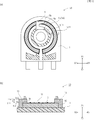
- A A plan view schematically showing a main part of a variable resistor as an embodiment of the present invention, (b) A cross-sectional view taken along the line AA of FIG. 1 (a). An exploded perspective view showing a variable resistor as an embodiment of the present invention.
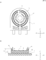
- A A plan view schematically showing a modification of a main part of a variable resistor as an embodiment of the present invention, (b) a sectional view taken along the line AA of FIG. 3 (a).
- A A plan view schematically showing another modification of the main part of the variable resistor as the embodiment of the present invention, (b) A cross-sectional view taken along the line AA of FIG. 4 (a).
- Graph showing weight loss due to heat of oil due to TG-DTA Graph showing the measurement results of Example 1 and Comparative Examples 4 to 5
- FIG. 1A is a plan view schematically showing a main part of a variable resistor according to an embodiment of the present invention
- FIG. 1B is a cross-sectional view taken along the line AA of FIG. 1A. is there.
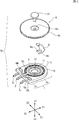
- FIG. 2 is an exploded perspective view showing a variable resistor.
- the variable resistor 50 is formed of a substrate 1, a knob member 8, a sliding member 9, and a shaft member 10.
- the substrate 1 has a first circular base portion 1a and a second base portion 1b protruding rectangularly from the first base portion 1a, and a central hole 1c is provided in the center of the first base portion 1a. ing.
- the substrate 1 has a resistor 5 formed on its surface, and is mainly composed of an insulating molded body such as a phenol laminated substrate, an epoxy substrate containing glass, a molding resin substrate, and a ceramics substrate.
- an insulating molded body such as a phenol laminated substrate, an epoxy substrate containing glass, a molding resin substrate, and a ceramics substrate.
- a current collecting portion 4 made of a conductive material containing silver or the like is provided in an annular shape around the central hole 1c.
- the terminal 2 is connected to the lower surface of the current collector 4 (the surface on the Z1-Z2 axis Z2 side), and the current collector 4 and the terminal 2 are set to the same potential.
- a resistor 5 having an arc shape in which a part of the annulus is cut is provided on the outer circumference of the current collector 4.
- the ends 5a and 5b of the resistor 5 are electrically connected to the terminals 3a and 3b via the electrodes 6A and 6B, respectively, and the terminals 3a and 3b and the ends 5a and 5b of the resistor 5 are connected to each other, respectively. It is set to the same potential.
- the resistor 5 is usually formed by using a resistor paste in which a conductor such as carbon black is dispersed in a binder resin dissolved in an appropriate solvent and a solvent is further added as needed.
- a pattern having a predetermined shape is formed using the resistor paste by a known screen printing or the like to obtain the resistor 5.
- it may be dried to remove the solvent and fired.
- a phenol resin, a polyimide resin, or the like is used to impart heat resistance and the like. Further, it is preferable to add a filler such as carbon fiber or silicon oxide to the resistor paste in order to impart wear resistance and the like. Further, in addition to the above materials, additives such as a defoaming agent can be added to the resistor paste forming the resistor 5.
- the sliding member 9 slides along the resistor 5. As described above, it is rotatably mounted on the substrate 1. As a result, the rotary type variable resistor 50 is obtained.
- the pattern of the resistor 5 is not limited to the arc shape.
- the sliding member 9 is formed in an elongated shape, the sliding member 9 is slidably mounted on the substrate 1 so as to slide along the resistor 5, whereby the sliding type variable resistor 50 is obtained. Be done.
- a pair of electrodes 6A and 6B are provided by screen-printing a conductive paste such as silver on the substrate 1 before providing the resistor 5.
- a pattern of a resistor 5 having an arc shape or the like is provided so as to connect the pair of electrodes 6A and 6B, and electrodes 6A and 6B are provided at both ends 5a and 5b of the resistor 5.
- the resistor 5 is preferably provided so as to cover the electrodes 6A and 6B from above.
- oil 11 is applied to the surfaces of the current collector 4 and the resistor 5.
- the oil 11 functions as a lubricant for improving the wear resistance of the surfaces of the current collector 4 and the resistor 5, and for example, a fluorine-based oil can be used.
- a fluorine-based oil can be used.
- the fluorine-based oil include perfluoroalkyl polyethers and perfluoropolyethers, and either linear type or side chain type can be used.
- oils and additives can be mixed with the oil 11 if necessary, but among the materials constituting the fluorine-based oil, for example, 80% by weight or more is preferably the fluorine-based oil, and 100% by weight. Is more preferable.
- the oil 11 functions as a lubricant and the performance of the variable resistor 50 deteriorates. From the viewpoint of preventing the above, 0.07 ⁇ m or more is preferable, 0.2 ⁇ m or more is more preferable, and 0.8 ⁇ m or more is further preferable. From the viewpoint of maintaining stable contact between the resistor 5 and the sliding member 9, the thickness is preferably 3 ⁇ m or less.
- the weight average molecular weight of the oil 11 is preferably 2000 to 18000, more preferably 4500 to 18000.
- the kinematic viscosity at 20 ° C. is preferably 40 to 500 [mm 2 / s] (cSt), more preferably 150 to 500 [mm 2 / s].
- the type of oil 11 used as a lubricant is not limited.
- Examples of commercially available products that can be used as the oil 11 include Solvay Specialty Polymers, Fomblin series; Daikin Industries, Demnum series; Chemours, Krytox series; Moresco, Morescophospharol and the like.
- the oil-repellent portion 15 is from the side where the resistor 5 of the substrate 1 is arranged (Z1 side of the ZZ2 axis of FIG. 1B). It is provided so as to surround at least a part of the resistor 5 in a plan view. Since the oil-repellent portion 15 has a smaller surface free energy (surface tension) than the resistor 5, it is difficult for the oil 11 to get wet (hereinafter, appropriately referred to as "small wettability"). When the oil-repellent portion 15 surrounding the resistor 5 repels the oil 11, the flow of the oil 11 on the surface of the resistor 5 can be suppressed and the oil 11 can be held on the surface of the resistor 5.
- the oil 11 can be held on the surface of the resistor 5 and maintained at a predetermined film thickness. Therefore, for example, it is possible to use a low molecular weight and low kinematic viscosity oil 11 having a weight average molecular weight of 2000 to 5500 and a kinematic viscosity of about 40 to 70 [mm 2 / s] (cSt) at 20 ° C. is there.
- the surface free energy of the oil-repellent portion 15 is preferably 50 [mJ / m 2 ] or less, and more preferably 40 [mJ / m 2 ] or less.
- the surface free energy is a value calculated from the contact angles of three types of liquids (water, bromonaphthalene, and ethylene glycol) having known surface free energies based on the Kitazaki-Hata theory.
- the oil-repellent portion 15 is usually formed by using a resin paste obtained by adding an additive such as a pigment or an antifoaming agent to a resin dissolved in an appropriate solvent as needed.
- a pattern of a resin paste having a predetermined shape is formed on the surface of the resistor 5 by using a known screen printing or the like to form an oil-repellent portion 15.
- the solvent may be removed by drying and firing may be performed, if necessary.
- the resin contained most in the resin paste used for forming the oil-repellent portion 15 is appropriately referred to as "base resin".
- the resin contained in the resin paste include thermosetting resins such as epoxy resin, polyimide and melamine, thermoplastic resins such as polyethylene, polypropylene, polystyrene and polycarbonate, and photocurable resins. From the viewpoint of forming the oil-repellent portion 15 having a low surface free energy, a resin having a low ⁇ OH content is preferable, and a resin containing no ⁇ OH is more preferable. Further, a thermosetting resin is preferable from the viewpoint of resistance to oil 11.
- the oil-repellent portion 15 is the resistor 5 along the peripheral edge 5E of the resistor 5 in a plan view (when the XY plane of the substrate 1 in FIG. 1A is viewed from the Z1 side in FIG. 1B). It is arranged around the perimeter of.
- the oil-repellent portion 15 can maintain a state in which the entire surface of the pattern of the resistor 5 is covered with the layer of oil 11.
- the oil-repellent portion 15 is continuously provided on the peripheral edge 5E of the resistor 5.
- "provided continuously on the peripheral edge 5E” means that the peripheral edge 5E of the pattern of the resistor 5 is in contact with the oil-repellent portion 15, and a gap through which the oil 11 flows is not formed between the two.
- the oil 11 is prevented from flowing out from the gap between the peripheral edge 5E and the oil-repellent portion 15, and the state in which the film of the oil 11 is formed on the surface of the resistor 5 with a predetermined film thickness is maintained. Can be done.
- the height from the surface 1S of the substrate 1 to the surface 15S of the oil-repellent portion 15 (the thickness of the oil-repellent portion 15 in the Z1-Z2 axial direction) h1 is the height from the surface 1S of the substrate 1 to the surface 5S of the resistor 5. (Thickness of resistor 5 in the Z1-Z2 axis direction) is larger than h2. Therefore, the oil-repellent portion 15 has an action based on the difference in surface free energy from the resistor 5 and an action based on the difference in height from the surface 1S of the substrate 1, so that the oil on the surface of the resistor 5 is oiled. 11 can be stably held.
- the film thickness of the resistor 5 is about 10 to 15 ⁇ m
- the film thickness of the oil repellent portion 15 in the Z1-Z2 axis direction is preferably about 20 to 50 ⁇ m.
- the difference between the height h1 and the height h2 described above, that is, the height X from the surface 5S of the resistor 5 to the surface 15S of the oil-repellent portion 15 is preferably 10 to 40 ⁇ m, preferably 15 to 35 ⁇ m, and 20 to 20 to. 30 ⁇ m is more preferable.
- the oil repellent portion 15 has an overlapping portion 15L arranged on the surface of the resistor 5.
- the overlap portion 15L refers to a portion provided on the surface of the resistor 5 which is superimposed on the resistor 5 when the substrate 1 is viewed in a plan view from the Z1 side of the Z1-Z2 axis of FIG. 1 (b).
- the knob member 8 is formed of an insulating material in a disk shape, and a hole 8a is provided in the center thereof. Further, an uneven portion 8b is formed on the outer edge of the picking member 8. When the knob member 8 is rotated, the uneven portion 8b prevents slippage between the member that imparts rotation and the outer edge.
- a sliding member 9 formed of a metal leaf spring such as phosphor bronze is fixed to the lower part of the picking member 8.
- the sliding member 9 has a slider 9a that slides while lightly oppressing the surface of the current collector 4, and a slider 9b that slides while lightly oppressing the surface of the resistor 5. There is. Of the slider 9a and the slider 9b, the portion in contact with the current collector 4 and the resistor 5 is the sliding contact.
- a noble metal material that can maintain good contact with the resistor 5 even during long-term sliding is used.
- nickel silver (copper-zinc-nickel alloy) with gold-plated or silver-plated surface, or alloys such as palladium, silver, platinum, and nickel can be used.
- a noble metal alloy when surface oxidation is a concern at high temperatures, it is desirable to use a noble metal alloy to maintain a stable contact state.
- the shaft member 10 is inserted through the hole 8a of the knob member 8 and the center hole 1c of the substrate 1, and the tip of the shaft member 10 is the back surface of the substrate 1 so that the shaft member 10 does not come out of the center hole 1c of the substrate 1. It is held on the side.
- the knob member 8 can rotate integrally with the sliding member 9 while facing the substrate 1.
- the sliders 9a and 9b of the sliding member 9 slide on the surfaces of the current collector 4 and the resistor 5, respectively, so that the resistance between the terminals 2 and the terminals 3a and 3b The value can be changed. Since the position of the external moving body interlocked with the rotation of the picking member 8 can be detected by the resistance value, the variable resistor 50 can be used as the position detecting device. A constant voltage may be applied between the terminals 3a and the terminals 3b, and the potential at the position where the slider 9b contacts may be used as an output to detect the position from the change in the output voltage.
- FIG. 3A is a plan view schematically showing a modified example of a main part of the variable resistor as an embodiment of the present invention
- FIG. 3B is a view taken along the line AA of FIG. 3A. It is a sectional view.
- the oil-repellent portion 15 can be configured to include only the overlap portion 15L arranged on the surface of the resistor 5.
- FIG. 4 (a) is a plan view schematically showing another modification of the main part of the variable resistor as the embodiment of the present invention
- FIG. 4 (b) is a plan view schematically showing another modification of the main part of the variable resistor. It is a cross-sectional view taken along the line.
- the oil-repellent portion 15 may be configured not to include the overlap portion 15L arranged on the surface of the resistor 5.
- the height h2 from the surface of the substrate to the surface of the oil-repellent portion 15 is larger than the sum of the height h1 from the surface of the substrate to the surface of the resistor and the film thickness of the oil 11 (h2> h1 + oil film thickness). ).
- Example 1 An amount of oil having an initial oil film thickness of 1.2 ⁇ m was applied to the resistor provided with the oil repellent portion, and the oil film thickness on the surface of the resistor was measured after the high temperature standing test (86 hours later).
- a resistor was formed on the substrate using a resin paste (carbon black graphite for the conductor and phenolic resin for the binder resin).
- the height h2 from the substrate surface to the resistor surface was 12 to 13 ⁇ m.
- the surface free energy of the resistor was 54.6 [mJ / m 2 ].
- the oil-repellent portion was formed by using a resin paste containing an epoxy resin at a concentration of about 60% by weight as a base resin.
- the height h1 from the substrate surface to the surface of the oil-repellent portion is 36 to 38 ⁇ m, and the difference X between h1 and the height h2 of the resistor is 23 to 26 ⁇ m (see FIGS. 1 (a) and 1 (b)).
- An oil-repellent portion was formed so as to surround the periphery of the.
- the surface free energy of the oil-repellent portion was 39.9 [mJ / m 2 ].
- Example 1 The same resistor as in Example 1 was formed except that it was not provided with an oil repellent portion.
- the same oil as in Example 1 was applied to the surface of the resistor in an amount such that the film thickness was 0.7 ⁇ m, 1.2 ⁇ m, and 1.6 ⁇ m (Comparative Examples 1, 2, and 3), and after a high temperature standing test (86 hours later). ), The film thickness of the oil on the surface of the resistor was measured.
- ⁇ Test method> As a standing test under high temperature conditions assuming long-term storage, the film thickness of the oil present on the surface of the resistor was measured after standing for 86 hours under 128 ° C. conditions. At the same time, the condition of the resistor surface after the test was visually confirmed. The posture of the variable resistor when left under high temperature conditions was such that the XY plane of the substrate 1 (see FIG. 1A) was in the vertical direction.
- Example 1 The measurement results of Example 1 and Comparative Examples 1 to 3 are shown in Table 1 and FIG.
- the resistor of the variable resistor of Example 1 maintained a wet state with a dark surface color of the resistor coated with oil even after the high temperature standing test. Further, the film thickness of the oil on the surface of the resistor was maintained at a sufficient film thickness to perform the lubrication function. From this result, it was found that the film thickness of the oil formed on the surface of the resistor can be maintained for a long period of time under high temperature conditions by providing the oil-repellent portion so as to surround the pattern of the resistor. On the other hand, none of the resistors of the variable resistors of Comparative Examples 1 to 3 had a light color on the surface of the oil-coated resistors and did not maintain a wet state. Further, the film thickness of the oil on the surface of the resistor was not sufficient to perform the lubrication function.
- ⁇ Comparative example 4> The standing test under high temperature conditions was carried out in the same manner as in Example 1 except that the resin paste used for forming the oil-repellent portion was changed as follows. Instead of the resin paste of Example 1, a resin paste containing xylene resin at a concentration of about 50% by weight was used as the base resin. The surface free energy of the oil-repellent portion was 136.9 [mJ / m 2 ].
- Example 1 The measurement results of Example 1 and Comparative Examples 4 to 5 are shown in Table 2 and FIG.
- the oil-repellent portion of Comparative Examples 4 and 5 have a larger surface free energy than the resistor and have good wettability with the oil, it is possible to suppress the oil on the surface of the resistor from flowing to a portion other than the surface of the resistor. It is probable that it was not.
- the oil-repellent portion of Example 1 formed by using the resin paste using epoxy as the base resin has a smaller surface free energy than the resistor.
- the oil on the surface of the resistor could be suppressed from flowing to other parts by the action of repelling the oil in the oil-repellent portion which is poorly wetted with the oil. From these results, the surface free energy is smaller than that of the resistor so that the oil-repellent portion provided so as to surround the resistor acts as a barrier to prevent the oil on the surface of the resistor from flowing to other parts. It can be said that it is necessary that the wetness with oil is poor. Therefore, it is preferable to use a resin having an oil-repellent property as the base resin of the resin paste that forms the oil-repellent portion.
- the present invention is a highly reliable variable resistor under high temperature conditions, and can be used, for example, as a position detection device or the like.
- Substrate 1S Surface 1a: First base 1b: Second base 1c: Center hole 2, 3a, 3b: Terminal 4: Current collector 5: Resistor 5E: Peripheral 5S: Surface 5a, 5b: Edge 6A, 6B: Electrode 8: Picking member 8a: Hole 8b: Concavo-convex portion 9: Sliding member 9a, 9b: Slider 10: Shaft member 11: Oil 15: Oil repellent portion 15L: Overlapping portion 15S: Surface 50: Variable resistors X, h1, h2: Height
Landscapes
- Engineering & Computer Science (AREA)
- Microelectronics & Electronic Packaging (AREA)
- Manufacturing & Machinery (AREA)
- Adjustable Resistors (AREA)
- Apparatuses And Processes For Manufacturing Resistors (AREA)
Abstract
基板1と、基板1に配置された抵抗体5と、抵抗体5の表面5Sに塗布されたオイル11と、オイル11が塗布された抵抗体5の表面5Sを摺動する摺動部材9と、を備え、摺動部材9が抵抗体5に接触する位置の変化に伴って、出力が変化する本発明の可変抵抗器50は、基板1の抵抗体5が配置された側からの平面視において、抵抗体5の少なくとも一部を取り囲んで、抵抗体5よりも表面自由エネルギーが小さい撥油部15を備えているため、抵抗体表面を凹凸形状に形成することなく、抵抗体表面に安定的にオイルを保持することができる。
Description
本発明は、抵抗体の表面を摺動部材が移動することにより抵抗値が変化する、例えば、位置検出装置等として用いられる可変抵抗器に関する。
可変抵抗器は、抵抗体が設けられた基板と、抵抗体上をその表面に触れた状態のままで移動(摺動)する摺動部材とを備えている。導電体を含む抵抗体上を摺動部材が摺動して相対的な位置が変化することにより、両者に接続された回路の電気抵抗値が変動する。このため、可変抵抗器は、例えば、抵抗値に対応して変化する電圧に基づいて、摺動部材と連動する外部移動体の位置を検出することができる。
可変抵抗器においては、摺動ノイズを小さくすること(マイクロリニアリティ)による信頼性や、抵抗体表面を摺動体が擦動する際の耐摩耗性を向上させるため、オイル等の潤滑剤が抵抗体表面に塗布されることがある。この場合、潤滑作用を維持するためには、抵抗体表面にオイルを保持する必要がある。例えば、特許文献1には、抵抗体(膜)表面の少なくとも一部が凹凸形状にされてなるポジションセンサが記載されている。
しかし、特許文献1に記載のポジションセンサは、抵抗体表面の一部が凹凸形状に形成されることにより微小な範囲での抵抗値の変化が発生するので、マイクロリニアリティが悪くなるという問題がある。また、抵抗体表面に所定の凹凸形状を形成することは、生産性の低下につながるという問題もある。
本発明は、抵抗体表面を凹凸形状に形成することなく、その表面に安定的にオイルを保持することができる可変抵抗器の提供を目的とする。
本発明は、抵抗体表面を凹凸形状に形成することなく、その表面に安定的にオイルを保持することができる可変抵抗器の提供を目的とする。
本発明の可変抵抗器は、基板と、前記基板に配置された抵抗体と、前記抵抗体の表面に塗布されたオイルと、前記オイルが塗布された前記抵抗体の表面を摺動する摺動部材とを備え、前記摺動部材が前記抵抗体に接触する位置の変化に伴って出力が変化する可変抵抗器において、前記基板の前記抵抗体が配置された側からの平面視において、前記抵抗体の少なくとも一部を取り囲む、前記抵抗体よりも表面自由エネルギーが小さい撥油部を備えていることを特徴とする。
表面自由エネルギーが抵抗体よりも小さい撥油部で取り囲むことにより、抵抗体の表面にオイルの膜を保持することができる。
表面自由エネルギーが抵抗体よりも小さい撥油部で取り囲むことにより、抵抗体の表面にオイルの膜を保持することができる。
前記オイルは、重量平均分子量が2000以上であり、20℃における動粘度が40[mm2/s]以上あればよい。この性質を備えたオイルを用いることにより、抵抗体の全抵抗値が変化することを抑制できる。
前記撥油部の前記表面自由エネルギーが50[mJ/m2]以下であることが好ましい。前記撥油部が、エポキシ樹脂をベース樹脂とする樹脂ペーストを用いて形成されていることが好ましい。これらの構成により撥油部の撥油性が高くなるから、動粘度が低いオイルの膜を抵抗体表面に安定的に保持することができる。
前記撥油部の前記表面自由エネルギーが50[mJ/m2]以下であることが好ましい。前記撥油部が、エポキシ樹脂をベース樹脂とする樹脂ペーストを用いて形成されていることが好ましい。これらの構成により撥油部の撥油性が高くなるから、動粘度が低いオイルの膜を抵抗体表面に安定的に保持することができる。
前記撥油部が、平面視において、前記抵抗体の周縁に沿って、前記抵抗体の周囲を取り囲んで配置されていることが好ましい。前記基板の表面から前記撥油部の表面までの高さが、前記基板の表面から前記抵抗体の表面までの高さよりも大きいことが好ましい。前記撥油部が、前記抵抗体の表面上に配置されたオーバーラップ部を有することが好ましい。これらの構成により、オイルの膜が抵抗体と撥油部との間から拡散することを防いで、オイルの膜を抵抗体表面に安定的に保持することができる。
本発明の可変抵抗装置は、抵抗体の周囲にオイルの濡れ性が小さい撥油部を配置することにより、抵抗体表面のオイルが抵抗体の表面以外の部分に流れることを防止する。したがって、抵抗体表面に凹凸形状を形成することなく、抵抗体表面にオイルを安定的に保持することができる。
本発明の実施形態について、以下、図を参照しつつ説明する。各図において、同一の部材に同じ番号を付して、適宜、説明を省略する。
図1(a)は本発明の実施の形態としての可変抵抗器の要部を模式的に示す平面図であり、図1(b)は図1(a)のA-A矢視断面図である。図2は可変抵抗器を示す分解斜視図である。
可変抵抗器50は、基板1と、摘み部材8、摺動部材9および軸部材10で形成されている。基板1は、円形状の第1の基部1aと、第1の基部1aから矩形状に突出する第2の基部1bとを有し、第1の基部1aの中央には中心孔1cが設けられている。
可変抵抗器50は、基板1と、摘み部材8、摺動部材9および軸部材10で形成されている。基板1は、円形状の第1の基部1aと、第1の基部1aから矩形状に突出する第2の基部1bとを有し、第1の基部1aの中央には中心孔1cが設けられている。
基板1は、その表面に抵抗体5が形成されるものであり、フェノール積層基板、ガラス入りエポキシ基板、成形樹脂基板、セラミックス基板等の主として絶縁性の成形体からなる。
第1の基部1aの表面には、銀等を含む導電材料からなる集電部4が中心孔1cの回りに環状に設けられている。端子2は集電部4の下面(Z1-Z2軸Z2側の面)に接続されており、集電部4と端子2とは同電位に設定されている。
集電部4の外周には円環の一部が切断された円弧形状からなる抵抗体5が設けられている。抵抗体5の端部5a、5bはそれぞれ、電極6A、6Bを介して、端子3a、3bと電気的に接続されており、端子3a、3bと抵抗体5の端部5a、5bとはそれぞれ同電位に設定されている。
抵抗体5は、通常、適当な溶剤に溶解したバインダ樹脂中にカーボンブラック等の導電体を分散するとともに、必要に応じてさらに溶剤を加えてなる抵抗体ペーストを用いて形成される。公知のスクリーン印刷等により、抵抗体ペーストを用いて所定形状のパターンを形成し、抵抗体5とする。抵抗体5の形成においては、必要に応じて乾燥して溶剤を除去して焼成してもよい。
抵抗体ペーストのバインダ樹脂としては、耐熱性等の付与のためにフェノール樹脂やポリイミド樹脂等が用いられる。また、抵抗体ペーストには、耐摩耗性付与等のためにカーボンファイバ、酸化ケイ素等のフィラーを配合することが好ましい。また、抵抗体5を形成する抵抗体ペーストには、上記材料の他、消泡剤等の添加剤を加えることもできる。
抵抗体5は、図1(a)、図1(b)、図2に示すように、円弧形状(馬蹄形状)に形成される場合、摺動部材9が抵抗体5に沿って摺動するように、基板1に対して回転可能に装着される。これにより、回転型の可変抵抗器50が得られる。ただし、抵抗体5のパターンは、円弧形状に限られない。例えば、細長形状に形成された場合、摺動部材9が抵抗体5に沿って摺動するように、基板1に対してスライド可能に装着されることにより、スライド型の可変抵抗器50が得られる。
通常は、抵抗体5を設ける前に、基板1の上に銀等の導電ペーストをスクリーン印刷等することにより、1対の電極6A、6Bが設けられる。当該1対の電極6A、6Bをつなぐ様に、円弧形状等の抵抗体5のパターンが設けられて、抵抗体5の両端部5a、5bに電極6A、6Bが設けられた構成とされる。抵抗体5は、電極6A、6Bを上から覆う様に設けることが好ましい。
図1(a)および図1(b)に示すように集電部4および抵抗体5の表面にはオイル11が塗布されている。オイル11は、集電部4および抵抗体5の表面の耐摩耗性を向上させる潤滑剤として機能するものであり、たとえば、フッ素系オイルを用いることができる。フッ素系オイルとして、パーフルオロアルキルポリエーテル、パーフルオロポリエーテル等が挙げられ、直鎖型、側鎖型のいずれをも用いることができる。
オイル11には、必要に応じて他のオイルや添加剤を混合することもできるが、フッ素系オイルを構成する材料中、例えば80重量%以上がフッ素系オイルであることが好ましく、100重量%であることがより好ましい。
抵抗体5の上に層状に形成されるオイル11の膜厚(図1(b)のZ1-Z2軸方向の厚さ)は、オイル11が潤滑剤として機能し、可変抵抗器50の性能劣化を防止する観点から、0.07μm以上が好ましく、0.2μm以上がより好ましく、0.8μm以上がさらに好ましい。抵抗体5と摺動部材9との安定的な接触を維持する観点から、好ましくは3μm以下とされる。
オイル11の重量平均分子量は、2000~18000が好ましく、4500~18000がより好ましい。20℃における動粘度は、40~500[mm2/s](cSt)が好ましく、150~500[mm2/s]がより好ましい。
潤滑剤として用いられるオイル11の種類は限定されない。オイル11として使用可能な市販品として、Solvay Specialty Polymers製の、Fomblinシリーズ;ダイキン工業製、デムナムシリーズ;Chemours製、Krytoxシリーズ;Moresco製、モレスコホスファロール等が挙げられる。
撥油部15は、図1(a)および図1(b)に示すように、基板1の抵抗体5が配置された側(図1(b)のZ-Z2軸のZ1側)からの平面視において、抵抗体5の少なくとも一部を取り囲むように設けられている。撥油部15は、抵抗体5よりも表面自由エネルギー(表面張力)が小さいから、オイル11によって濡れにくい(以下、適宜「濡れ性が小さい」という)。抵抗体5を取り囲む撥油部15がオイル11を弾くことにより、抵抗体5の表面におけるオイル11の流動を抑えて、オイル11を抵抗体5の表面に保持することができる。このため、オイル11が低分子量かつ低動粘度である場合でも、オイル11を抵抗体5表面に保持して所定の膜厚に維持することができる。それゆえ、例えば、重量平均分子量が2000~5500、20℃における動粘度が40~70[mm2/s](cSt)程度である、低分子量かつ低動粘度のオイル11を用いることが可能である。
抵抗体5の表面にオイル11を保持する観点から、抵抗体5よりも撥油部15の濡れ性が小さくなるようにする。撥油部15の表面自由エネルギーは、50[mJ/m2]以下が好ましく、40[mJ/m2]以下がより好ましい。表面自由エネルギーは、北崎・畑理論に基づいて、表面自由エネルギーが既知の値の3種類の液体(水、ブロモナフタレン、エチレングリコール)の接触角を測定し、その値より算出した値をいう。
撥油部15は、通常、適当な溶剤に溶解した樹脂に、必要に応じて顔料や消泡剤等の添加剤を加えてなる樹脂ペーストを用いて形成される。抵抗体5の表面に公知のスクリーン印刷等を用いて所定形状の樹脂ペーストのパターンを形成し、撥油部15とする。撥油部15の形成において、必要に応じて乾燥による溶剤の除去および焼成を行ってもよい。撥油部15の形成に用いられる樹脂ペースト中に最も多く含まれる樹脂を、適宜「ベース樹脂」という。
樹脂ペーストに含まれる樹脂の具体例としては、エポキシ樹脂、ポリイミド、メラミン等の熱硬化性樹脂、ポリエチレン、ポリプロピレン、ポリスチレン、ポリカーボネート等の熱可塑性樹脂、および光硬化性樹脂が挙げられる。表面自由エネルギーが低い撥油部15を形成する観点から、-OHの含有量が低い樹脂が好ましく、-OHを含有しない樹脂がより好ましい。また、オイル11に対する耐性の観点から、熱硬化性樹脂が好ましい。
撥油部15は、平面視(図1(a)における基板1のXY平面を、図1(b)のZ1側から見た場合)において、抵抗体5の周縁5Eに沿って、抵抗体5の周囲を取り囲んで配置されている。この撥油部15によって、抵抗体5のパターンの表面全体がオイル11の層で覆われた状態を保持することができる。
図1(b)に示すように、撥油部15は、抵抗体5の周縁5Eに連続して設けられている。ここで「周縁5Eに連続して設けられている」とは、抵抗体5のパターンの周縁5Eが撥油部15に接しており、両者の間にオイル11が流動する隙間が形成されていないことをいう。この構成により、周縁5Eと撥油部15との間のすき間からオイル11が流れ出ることを防止し、オイル11の膜が所定の膜厚で抵抗体5の表面に形成された状態を維持することができる。
基板1の表面1Sから撥油部15の表面15Sまでの高さ(撥油部15のZ1-Z2軸方向の膜厚)h1は、基板1の表面1Sから抵抗体5の表面5Sまでの高さ(抵抗体5のZ1-Z2軸方向の膜厚)h2よりも大きい。このため、撥油部15は、抵抗体5との表面自由エネルギーとの違いに基づく作用に加えて、基板1の表面1Sからの高さの違いに基づく作用により、抵抗体5の表面にオイル11を安定して保持することができる。
例えば、抵抗体5の膜厚が10~15μm程度の場合、撥油部15のZ1-Z2軸方向の膜厚は20~50μm程度が好ましい。上述した高さh1と高さh2との差、すなわち、抵抗体5の表面5Sから撥油部15の表面15Sまでの高さXは、10~40μmが好ましく、15~35μmが好ましく、20~30μmがさらに好ましい。
撥油部15は、抵抗体5の表面上に配置されたオーバーラップ部15Lを有している。オーバーラップ部15Lは、図1(b)のZ1-Z2軸のZ1側から基板1を平面視した場合に、抵抗体5と重畳する、抵抗体5表面に設けられた部分をいう。抵抗体5表面にオーバーラップ部15Lを設けることにより、スクリーン印刷時に多少の位置ずれが発生したとしても、撥油部15と抵抗体5とが隙間なく連続的に形成される。このため、抵抗体5表面のオイル11が撥油部15と抵抗体5との間から、抵抗体5表面以外の部分に流れ出すことを防止できる。
図2に示すように、摘み部材8は、絶縁材料で円盤状に形成されており、その中央には孔8aが設けられる。また摘み部材8の外縁には凹凸部8bが形成されている。凹凸部8bは摘み部材8に回転を与えるときに、回転を付与する部材と外縁との間の滑りを防止する。
摘み部材8の下部には、りん青銅等の金属製板バネで形成された摺動部材9が固着されている。そして、摺動部材9は、集電部4の表面を軽く弾圧しながら摺動する摺動子9aと、抵抗体5の表面を軽く弾圧しながら摺動する摺動子9bとを有している。なお、摺動子9aおよび摺動子9bのうち、集電部4および抵抗体5に接する部分が摺動接点である。
摺動部材9としては、長期の摺動においても抵抗体5と良好な接触を保ち得る貴金属性の材料が用いられる。具体的には洋白(銅亜鉛ニッケル合金)の表面に金メッキや銀メッキを施したものや、パラジューム、銀、白金あるいはニッケル等の合金を使用することができる。特に、高温で表面酸化が懸念される場合、安定した接触状態を維持するために貴金属合金を用いることが望ましい。
軸部材10は、摘み部材8の孔8aと基板1の中心孔1cに挿通されており、軸部材10が基板1の中心孔1cから抜けないように、軸部材10の先端が基板1の裏面側で保持されている。摘み部材8は基板1に対向しつつ摺動部材9と一体で回転可能となっている。
摘み部材8に回転を与えると、摺動部材9の摺動子9a、9bが集電部4と抵抗体5の表面をそれぞれ摺動するため、端子2と端子3a、3bとの間の抵抗値が可変させられる。抵抗値によって摘み部材8の回転と連動する外部移動体の位置を検出できるから、可変抵抗器50を位置検出装置として用いることができる。なお、端子3aと端子3bとの間に定電圧を印加し、摺動子9bが接触する位置における電位を出力として、出力電圧の変化から位置検出を行っても良い。
図3(a)は本発明の実施の形態としての可変抵抗器の要部の変形例を模式的に示す平面図であり、図3(b)は図3(a)のA-A矢視断面図である。これらの図に示すように、撥油部15は、抵抗体5の表面上に配置されたオーバーラップ部15Lのみからなる構成とすることができる。
図4(a)は本発明の実施の形態としての可変抵抗器の要部の他の変形例を模式的に示す平面図であり、図4(b)は図4(a)のA-A矢視断面図である。これらの図に示すように、撥油部15は、抵抗体5の表面上に配置されたオーバーラップ部15Lを備えていない構成とすることもできる。この場合、基板表面から撥油部15の表面までの高さh2が、基板表面から抵抗体表面までの高さh1とオイル11の膜厚との合計よりも大きくなる(h2>h1+オイル膜厚)ように構成する。
図4(a)は本発明の実施の形態としての可変抵抗器の要部の他の変形例を模式的に示す平面図であり、図4(b)は図4(a)のA-A矢視断面図である。これらの図に示すように、撥油部15は、抵抗体5の表面上に配置されたオーバーラップ部15Lを備えていない構成とすることもできる。この場合、基板表面から撥油部15の表面までの高さh2が、基板表面から抵抗体表面までの高さh1とオイル11の膜厚との合計よりも大きくなる(h2>h1+オイル膜厚)ように構成する。
以下、実施例等により本発明をさらに具体的に説明するが、本発明の範囲はこれらの実施例等に限定されるものではない。
(実施例1)
撥油部を備えた抵抗体に、初期のオイル膜厚が1.2μmとなる量のオイルを塗布し、高温放置試験後(86時間後)における抵抗体表面のオイル膜厚を測定した。
基板上に樹脂ペースト(導電体はカーボンブラック・グラファイト、バインダ樹脂はフェノール樹脂)を用いて抵抗体を形成した。基板表面から抵抗体表面までの高さh2(図1(b)参照)は、12~13μmとした。抵抗体の表面自由エネルギーは、54.6[mJ/m2]であった。
撥油部を備えた抵抗体に、初期のオイル膜厚が1.2μmとなる量のオイルを塗布し、高温放置試験後(86時間後)における抵抗体表面のオイル膜厚を測定した。
基板上に樹脂ペースト(導電体はカーボンブラック・グラファイト、バインダ樹脂はフェノール樹脂)を用いて抵抗体を形成した。基板表面から抵抗体表面までの高さh2(図1(b)参照)は、12~13μmとした。抵抗体の表面自由エネルギーは、54.6[mJ/m2]であった。
撥油部は、ベース樹脂としてエポキシ樹脂を約60重量%の濃度で含有する樹脂ペーストを用いて形成した。基板表面から撥油部表面までの高さh1を36~38μm、h1と抵抗体の高さh2との差Xを23~26μm(図1(a)図1(b)参照)として、抵抗体の周囲を取り囲むように撥油部を形成した。撥油部の表面自由エネルギーは、39.9[mJ/m2]であった。
<比較例1~3>
撥油部を備えない点を除いて、実施例1と同じ抵抗体を形成した。膜厚が0.7μm、1.2μm、1.6μm(比較例1、2、3)となる量で、実施例1と同じオイルを抵抗体表面に塗布し、高温放置試験後(86時間後)における抵抗体表面のオイルの膜厚を測定した。
撥油部を備えない点を除いて、実施例1と同じ抵抗体を形成した。膜厚が0.7μm、1.2μm、1.6μm(比較例1、2、3)となる量で、実施例1と同じオイルを抵抗体表面に塗布し、高温放置試験後(86時間後)における抵抗体表面のオイルの膜厚を測定した。
<試験方法>
長期間の保管を想定した高温条件下における放置試験として、128℃条件下86時間放置後において、抵抗体の表面に存在するオイルの膜厚を測定した。併せて、目視で試験後における抵抗体表面の状態を確認した。高温条件下で放置する際における可変抵抗器の姿勢は、基板1のXY平面(図1(a)参照)が鉛直方向となるようにした。
長期間の保管を想定した高温条件下における放置試験として、128℃条件下86時間放置後において、抵抗体の表面に存在するオイルの膜厚を測定した。併せて、目視で試験後における抵抗体表面の状態を確認した。高温条件下で放置する際における可変抵抗器の姿勢は、基板1のXY平面(図1(a)参照)が鉛直方向となるようにした。
実施例1および比較例1~3の測定結果を表1および図5に示す。

実施例1の可変抵抗器の抵抗体は、高温放置試験後においても、オイルを塗布した抵抗体の表面の色が濃く、濡れた状態を維持していた。また、抵抗体の表面におけるオイルの膜厚は潤滑機能を奏するために十分な膜厚を維持していた。この結果から、抵抗体のパターンの周囲を取り囲むように撥油部を設けることにより、抵抗体の表面に形成されたオイルの膜厚を高温条件下において長期間にわたり維持できることが分かった。対して、比較例1~3の可変抵抗器の抵抗体はいずれも、オイルを塗布した抵抗体の表面の色が薄く、濡れた状態を維持していなかった。また、抵抗体の表面におけるオイルの膜厚は、潤滑機能を奏するために十分な膜厚ではなかった。
図6に示す120℃および150℃条件における重量損失におけるグラフから、128℃条件下で86時間の高温放置試験により蒸発するオイルは10~20%程度であると考えられる。対して、比較例1~3では、高温放置試験後において、抵抗体表面のオイルが90%以上失われている。これらから、抵抗体表面のオイルが失われた理由は、オイルの蒸発ではなく、オイルの流動性が大きくなって抵抗体の表面とは別の場所に移動したことであると考えられる。
実施例1の可変抵抗器は、抵抗体を取り囲む撥油部がオイルの流動を抑えることにより、抵抗体表面にオイルの膜を維持できたといえる。
実施例1の可変抵抗器は、抵抗体を取り囲む撥油部がオイルの流動を抑えることにより、抵抗体表面にオイルの膜を維持できたといえる。
<比較例4>
撥油部を形成するために用いる樹脂ペーストを下記のように変更した以外は、実施例1と同様にして、高温条件下における放置試験を実施した。
実施例1の樹脂ペーストに代えて、ベース樹脂としてキシレン樹脂を約50重量%の濃度で含有する樹脂ペーストを用いた。撥油部の表面自由エネルギーは、136.9[mJ/m2]であった。
<比較例5>
撥油部を形成するために用いる樹脂ペーストを下記のように変更した以外は、実施例1と同様にして、高温条件下における放置試験を実施した。
実施例1の樹脂ペーストに代えて、ベース樹脂としてフェノール樹脂を約40重量%の濃度で含有する樹脂ペーストを用いた。撥油部の表面自由エネルギーは、159.8[mJ/m2]であった。
撥油部を形成するために用いる樹脂ペーストを下記のように変更した以外は、実施例1と同様にして、高温条件下における放置試験を実施した。
実施例1の樹脂ペーストに代えて、ベース樹脂としてキシレン樹脂を約50重量%の濃度で含有する樹脂ペーストを用いた。撥油部の表面自由エネルギーは、136.9[mJ/m2]であった。
<比較例5>
撥油部を形成するために用いる樹脂ペーストを下記のように変更した以外は、実施例1と同様にして、高温条件下における放置試験を実施した。
実施例1の樹脂ペーストに代えて、ベース樹脂としてフェノール樹脂を約40重量%の濃度で含有する樹脂ペーストを用いた。撥油部の表面自由エネルギーは、159.8[mJ/m2]であった。
実施例1および比較例4~5の測定結果を表2および図7に示す。
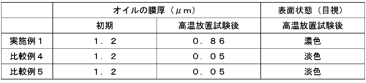
フェノールまたはキシレンをベース樹脂とする樹脂ペーストを用いて撥油部を形成した場合、高温放置試験後において、抵抗体の表面にオイルの膜厚を十分に維持することができなかった。比較例4および5の撥油部は、抵抗体よりも表面自由エネルギーが大きく、オイルとの濡れ性がよいことから、抵抗体表面のオイルが抵抗体表面以外の部分に流動することを抑制できなかったと考えられる。
対して、エポキシをベース樹脂とする樹脂ペーストを用いて形成した実施例1の撥油部は、抵抗体よりも表面自由エネルギーが小さい。このため、オイルとの濡れが悪い撥油部のオイルをはじく作用によって、抵抗体表面のオイルが他の部分に流動することを抑制できたといえる。
これらの結果から、抵抗体を囲むように設けた撥油部が、抵抗体表面のオイルが他の部分に流動することを防ぐ障壁として作用するには、抵抗体よりも表面自由エネルギーが小さく、オイルとの濡れが悪いことが必要といえる。このため、撥油部を形成する樹脂ペーストのベース樹脂としては、オイルをはじく性質を備えた樹脂を用いることが好ましい。
対して、エポキシをベース樹脂とする樹脂ペーストを用いて形成した実施例1の撥油部は、抵抗体よりも表面自由エネルギーが小さい。このため、オイルとの濡れが悪い撥油部のオイルをはじく作用によって、抵抗体表面のオイルが他の部分に流動することを抑制できたといえる。
これらの結果から、抵抗体を囲むように設けた撥油部が、抵抗体表面のオイルが他の部分に流動することを防ぐ障壁として作用するには、抵抗体よりも表面自由エネルギーが小さく、オイルとの濡れが悪いことが必要といえる。このため、撥油部を形成する樹脂ペーストのベース樹脂としては、オイルをはじく性質を備えた樹脂を用いることが好ましい。
本発明は、高温条件下における信頼性が高い可変抵抗器であり、例えば、位置検出装置等として用いることができる。
1 :基板
1S :表面
1a :第1の基部
1b :第2の基部
1c :中心孔
2、3a、3b:端子
4 :集電部
5 :抵抗体
5E :周縁
5S :表面
5a、5b:端部
6A、6B:電極
8 :摘み部材
8a :孔
8b :凹凸部
9 :摺動部材
9a、9b:摺動子
10 :軸部材
11 :オイル
15 :撥油部
15L :オーバーラップ部
15S :表面
50 :可変抵抗器
X、h1、h2:高さ
1S :表面
1a :第1の基部
1b :第2の基部
1c :中心孔
2、3a、3b:端子
4 :集電部
5 :抵抗体
5E :周縁
5S :表面
5a、5b:端部
6A、6B:電極
8 :摘み部材
8a :孔
8b :凹凸部
9 :摺動部材
9a、9b:摺動子
10 :軸部材
11 :オイル
15 :撥油部
15L :オーバーラップ部
15S :表面
50 :可変抵抗器
X、h1、h2:高さ
Claims (7)
- 基板と、前記基板に配置された抵抗体と、前記抵抗体の表面に塗布されたオイルと、前記オイルが塗布された前記抵抗体の表面を摺動する摺動部材とを備え、前記摺動部材が前記抵抗体に接触する位置の変化に伴って出力が変化する可変抵抗器において、
前記基板の前記抵抗体が配置された側からの平面視において、前記抵抗体の少なくとも一部を取り囲む、前記抵抗体よりも表面自由エネルギーが小さい撥油部を備えていることを特徴とする
可変抵抗器。 - 前記オイルは、重量平均分子量が2000以上であり、20℃における動粘度が40[mm2/s]以上である、請求項1に記載の可変抵抗器。
- 前記撥油部の前記表面自由エネルギーが50[mJ/m2]以下である、請求項1に記載の可変抵抗器。
- 前記撥油部が、エポキシ樹脂をベース樹脂とする樹脂ペーストを用いて形成されている、請求項1に記載の可変抵抗器。
- 前記撥油部が、平面視において、前記抵抗体の周縁に沿って、前記抵抗体の周囲を取り囲んで配置されている、請求項1に記載の可変抵抗器。
- 前記基板の表面から前記撥油部の表面までの高さが、前記基板の表面から前記抵抗体の表面までの高さよりも大きい、請求項1に記載の可変抵抗器。
- 前記撥油部が、前記抵抗体の表面上に配置されたオーバーラップ部を有する、請求項1に記載の可変抵抗器。
Priority Applications (3)
| Application Number | Priority Date | Filing Date | Title |
|---|---|---|---|
| JP2021508934A JP7170122B2 (ja) | 2019-03-25 | 2020-03-06 | 可変抵抗器 |
| CN202080014874.6A CN113454737B (zh) | 2019-03-25 | 2020-03-06 | 可变电阻器 |
| US17/394,037 US11631512B2 (en) | 2019-03-25 | 2021-08-04 | Variable resistor |
Applications Claiming Priority (2)
| Application Number | Priority Date | Filing Date | Title |
|---|---|---|---|
| JP2019056198 | 2019-03-25 | ||
| JP2019-056198 | 2019-03-25 |
Related Child Applications (1)
| Application Number | Title | Priority Date | Filing Date |
|---|---|---|---|
| US17/394,037 Continuation US11631512B2 (en) | 2019-03-25 | 2021-08-04 | Variable resistor |
Publications (1)
| Publication Number | Publication Date |
|---|---|
| WO2020195698A1 true WO2020195698A1 (ja) | 2020-10-01 |
Family
ID=72610059
Family Applications (1)
| Application Number | Title | Priority Date | Filing Date |
|---|---|---|---|
| PCT/JP2020/009628 Ceased WO2020195698A1 (ja) | 2019-03-25 | 2020-03-06 | 可変抵抗器 |
Country Status (5)
| Country | Link |
|---|---|
| US (1) | US11631512B2 (ja) |
| JP (1) | JP7170122B2 (ja) |
| CN (1) | CN113454737B (ja) |
| TW (1) | TWI731558B (ja) |
| WO (1) | WO2020195698A1 (ja) |
Cited By (1)
| Publication number | Priority date | Publication date | Assignee | Title |
|---|---|---|---|---|
| WO2022215391A1 (ja) * | 2021-04-08 | 2022-10-13 | アルプスアルパイン株式会社 | 抵抗体ポジションセンサ |
Citations (4)
| Publication number | Priority date | Publication date | Assignee | Title |
|---|---|---|---|---|
| JPS59126109A (ja) * | 1982-12-29 | 1984-07-20 | オリンパス光学工業株式会社 | グリ−スのにじみ出し防止装置 |
| JPH052941A (ja) * | 1991-06-25 | 1993-01-08 | Seiko Epson Corp | スイツチ基板 |
| JP2001288452A (ja) * | 2001-01-22 | 2001-10-16 | Hitachi Ltd | 物体の表面処理法,表面処理剤,表面処理された物品,部品及びそれらを備えた装置 |
| JP2006319274A (ja) * | 2005-05-16 | 2006-11-24 | Nidec Copal Corp | ポテンショメータ |
Family Cites Families (18)
| Publication number | Priority date | Publication date | Assignee | Title |
|---|---|---|---|---|
| US2827536A (en) * | 1954-11-04 | 1958-03-18 | Servomechanisms Inc | Method of fabricating film resistor elements |
| US2862088A (en) * | 1958-02-11 | 1958-11-25 | Acton Lab Inc | Hermetically sealed variable resistors and potentiometers |
| JPS6017197A (ja) * | 1983-07-08 | 1985-01-29 | 東洋紙業株式会社 | 紙の表面処理方法 |
| CN2161974Y (zh) * | 1993-05-10 | 1994-04-13 | 杨民 | 无噪声电位器 |
| US5554965A (en) * | 1994-11-02 | 1996-09-10 | The Erie Ceramic Arts Company | Lubricated variable resistance control having resistive pads on conductive path |
| AU743591B2 (en) * | 1997-01-31 | 2002-01-31 | Seydel Research, Inc. | Water dispersible/redispersible hydrophobic polyester resins and their application in coatings |
| JPH10223417A (ja) * | 1997-02-12 | 1998-08-21 | Aisan Ind Co Ltd | 摺動抵抗体の潤滑油塗布方法 |
| US6359545B1 (en) * | 1998-01-09 | 2002-03-19 | Capax B.V. | Adjustable resistor with slider made from elastomeric material |
| JP4288871B2 (ja) * | 2001-06-26 | 2009-07-01 | パナソニック電工株式会社 | 回転スイッチ |
| JP4583743B2 (ja) * | 2003-06-16 | 2010-11-17 | 株式会社村田製作所 | クリック機構付き回転型可変抵抗器 |
| JP2005150141A (ja) * | 2003-11-11 | 2005-06-09 | Alps Electric Co Ltd | 可変抵抗器 |
| US7605334B2 (en) | 2005-01-31 | 2009-10-20 | Kabushiki Kaisha Honda Lock | Rotary switch device |
| JP2007317971A (ja) | 2006-05-29 | 2007-12-06 | Mikuni Corp | ポジションセンサ |
| JP4955321B2 (ja) * | 2006-07-05 | 2012-06-20 | 協同油脂株式会社 | グリース組成物及び軸受 |
| JP5199498B2 (ja) | 2011-04-27 | 2013-05-15 | 株式会社日立製作所 | 電気接点用グリース及び摺動通電構造、電力用開閉機器、真空遮断器、真空絶縁スイッチギヤ、並びに真空絶縁スイッチギヤの組立方法 |
| CN103555141A (zh) * | 2013-10-28 | 2014-02-05 | 安徽明都电气有限公司 | 一种高耐水耐油性粉末涂料 |
| JPWO2016067769A1 (ja) * | 2014-10-31 | 2017-07-27 | 株式会社村田製作所 | 回転型可変抵抗器およびその製造方法 |
| CN106867327A (zh) * | 2016-12-22 | 2017-06-20 | 安徽易有墙纸有限公司 | 一种耐污耐油墙纸及其制备方法 |
-
2020
- 2020-01-20 TW TW109101954A patent/TWI731558B/zh active
- 2020-03-06 CN CN202080014874.6A patent/CN113454737B/zh active Active
- 2020-03-06 WO PCT/JP2020/009628 patent/WO2020195698A1/ja not_active Ceased
- 2020-03-06 JP JP2021508934A patent/JP7170122B2/ja active Active
-
2021
- 2021-08-04 US US17/394,037 patent/US11631512B2/en active Active
Patent Citations (4)
| Publication number | Priority date | Publication date | Assignee | Title |
|---|---|---|---|---|
| JPS59126109A (ja) * | 1982-12-29 | 1984-07-20 | オリンパス光学工業株式会社 | グリ−スのにじみ出し防止装置 |
| JPH052941A (ja) * | 1991-06-25 | 1993-01-08 | Seiko Epson Corp | スイツチ基板 |
| JP2001288452A (ja) * | 2001-01-22 | 2001-10-16 | Hitachi Ltd | 物体の表面処理法,表面処理剤,表面処理された物品,部品及びそれらを備えた装置 |
| JP2006319274A (ja) * | 2005-05-16 | 2006-11-24 | Nidec Copal Corp | ポテンショメータ |
Cited By (2)
| Publication number | Priority date | Publication date | Assignee | Title |
|---|---|---|---|---|
| WO2022215391A1 (ja) * | 2021-04-08 | 2022-10-13 | アルプスアルパイン株式会社 | 抵抗体ポジションセンサ |
| JP7604627B2 (ja) | 2021-04-08 | 2024-12-23 | アルプスアルパイン株式会社 | 抵抗体ポジションセンサ |
Also Published As
| Publication number | Publication date |
|---|---|
| JPWO2020195698A1 (ja) | 2021-11-25 |
| JP7170122B2 (ja) | 2022-11-11 |
| CN113454737A (zh) | 2021-09-28 |
| TW202043428A (zh) | 2020-12-01 |
| US11631512B2 (en) | 2023-04-18 |
| US20210366633A1 (en) | 2021-11-25 |
| TWI731558B (zh) | 2021-06-21 |
| CN113454737B (zh) | 2023-02-17 |
Similar Documents
| Publication | Publication Date | Title |
|---|---|---|
| JP5241180B2 (ja) | 先端に繊維を備えて接触させる技術を組入れた小型スリップ・リング | |
| US7362118B2 (en) | Probe with contact ring | |
| JP7170122B2 (ja) | 可変抵抗器 | |
| JP2014058682A (ja) | 末端コーティング | |
| JP6046796B2 (ja) | 改善された先端繊維接点設計ブラシ・アセンブリ | |
| JP5957693B2 (ja) | チップ抵抗器 | |
| JP2004031689A (ja) | 摺動接点と摺動型電気部品及びセンサ | |
| KR20160025625A (ko) | 슬라이딩형 전기 부품 | |
| RU2769371C1 (ru) | Электрический контактный элемент | |
| JPH03211802A (ja) | スイッチ付可変抵抗器 | |
| JP2022049477A (ja) | 抵抗基板及びそれを備える可変抵抗器 | |
| CN107077932A (zh) | 旋转型可变电阻器及其制造方法 | |
| US8466772B2 (en) | Precision variable resistor | |
| JP2005019103A (ja) | コネクタ接点材料および多極端子 | |
| US3188595A (en) | Adjustable resistor | |
| JP2005150141A (ja) | 可変抵抗器 | |
| JP7489614B2 (ja) | 抵抗基板及びそれを備える可変抵抗器 | |
| RU2793712C2 (ru) | Вращающееся контактное устройство | |
| WO2018224209A1 (de) | VARIABLER ELEKTRISCHER WIDERSTAND UND VERFAHREN ZUM ERKENNEN EINES VERSCHLEIßES AN EINEM SCHLEIFERKONTAKT DES VARIABLEN WIDERSTANDES | |
| RU2769459C1 (ru) | Электрический контактный элемент для высоких рабочих напряжений | |
| JP2006004865A (ja) | 摺動接点部材 | |
| KR102256592B1 (ko) | 저항식 선형 변위 변환기 | |
| JPH08177866A (ja) | 低発塵性転がり軸受 | |
| CN101283416B (zh) | 可变电阻器 | |
| JPS5923084B2 (ja) | 可変抵抗器 |
Legal Events
| Date | Code | Title | Description |
|---|---|---|---|
| 121 | Ep: the epo has been informed by wipo that ep was designated in this application |
Ref document number: 20779430 Country of ref document: EP Kind code of ref document: A1 |
|
| ENP | Entry into the national phase |
Ref document number: 2021508934 Country of ref document: JP Kind code of ref document: A |
|
| NENP | Non-entry into the national phase |
Ref country code: DE |
|
| 122 | Ep: pct application non-entry in european phase |
Ref document number: 20779430 Country of ref document: EP Kind code of ref document: A1 |