WO2020195521A1 - ヘッドマウントディスプレイ - Google Patents
ヘッドマウントディスプレイ Download PDFInfo
- Publication number
- WO2020195521A1 WO2020195521A1 PCT/JP2020/008121 JP2020008121W WO2020195521A1 WO 2020195521 A1 WO2020195521 A1 WO 2020195521A1 JP 2020008121 W JP2020008121 W JP 2020008121W WO 2020195521 A1 WO2020195521 A1 WO 2020195521A1
- Authority
- WO
- WIPO (PCT)
- Prior art keywords
- attachment
- display unit
- user
- head
- mounted display
- Prior art date
- Legal status (The legal status is an assumption and is not a legal conclusion. Google has not performed a legal analysis and makes no representation as to the accuracy of the status listed.)
- Ceased
Links
Images




Classifications
-
- G—PHYSICS
- G02—OPTICS
- G02B—OPTICAL ELEMENTS, SYSTEMS OR APPARATUS
- G02B27/00—Optical systems or apparatus not provided for by any of the groups G02B1/00 - G02B26/00, G02B30/00
- G02B27/01—Head-up displays
- G02B27/017—Head mounted
- G02B27/0176—Head mounted characterised by mechanical features
-
- G—PHYSICS
- G09—EDUCATION; CRYPTOGRAPHY; DISPLAY; ADVERTISING; SEALS
- G09F—DISPLAYING; ADVERTISING; SIGNS; LABELS OR NAME-PLATES; SEALS
- G09F9/00—Indicating arrangements for variable information in which the information is built-up on a support by selection or combination of individual elements
-
- H—ELECTRICITY
- H04—ELECTRIC COMMUNICATION TECHNIQUE
- H04N—PICTORIAL COMMUNICATION, e.g. TELEVISION
- H04N5/00—Details of television systems
- H04N5/64—Constructional details of receivers, e.g. cabinets or dust covers
-
- G—PHYSICS
- G02—OPTICS
- G02B—OPTICAL ELEMENTS, SYSTEMS OR APPARATUS
- G02B27/00—Optical systems or apparatus not provided for by any of the groups G02B1/00 - G02B26/00, G02B30/00
- G02B27/01—Head-up displays
- G02B27/0149—Head-up displays characterised by mechanical features
- G02B2027/0154—Head-up displays characterised by mechanical features with movable elements
-
- G—PHYSICS
- G02—OPTICS
- G02B—OPTICAL ELEMENTS, SYSTEMS OR APPARATUS
- G02B27/00—Optical systems or apparatus not provided for by any of the groups G02B1/00 - G02B26/00, G02B30/00
- G02B27/01—Head-up displays
- G02B27/0149—Head-up displays characterised by mechanical features
- G02B2027/0169—Supporting or connecting means other than the external walls
-
- G—PHYSICS
- G02—OPTICS
- G02B—OPTICAL ELEMENTS, SYSTEMS OR APPARATUS
- G02B27/00—Optical systems or apparatus not provided for by any of the groups G02B1/00 - G02B26/00, G02B30/00
- G02B27/01—Head-up displays
- G02B27/0179—Display position adjusting means not related to the information to be displayed
- G02B2027/0181—Adaptation to the pilot/driver
Definitions
- This disclosure relates to a head-mounted display.
- a head-mounted display that provides a user with an image related to virtual reality (VR) or augmented reality (AR) is known.
- the head-mounted display is attached to the user's head so as to cover the user's eyes, and provides the user with an image related to virtual reality or augmented reality through an image display unit arranged in front of the user's eyes.
- An attachment that is in close contact with the user's face so that the user can see at least the front, and a fixture that is attached to the attachment and is attached to the attachment to fix the attachment to the user's head while maintaining the state of close contact with the user's face.
- headgear including A display unit that has a video display unit that displays video and is removable from the attachment. It has a lock mechanism provided on at least one of the attachment and the display unit, and the display unit is detachably fixed to the attachment.
- a head-mounted display is provided in which the attachment and the display unit are configured to engage with each other in the front-back direction of the user.
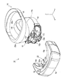
- a perspective view of a head-mounted display according to an embodiment of the present disclosure is exploded perspective view of a head-mounted display with the display unit separated.
- Perspective view of display unit and attachment Side view of display unit and attachment Top view of display unit and attachment
- the head-mounted display according to the embodiment of the present disclosure will be described below with reference to FIGS. 1 to 6.
- FIG. 1 is a perspective view showing a head-mounted display according to an embodiment of the present disclosure.
- FIG. 2 is a side view of the head-mounted display.
- FIG. 3 is an exploded perspective view of the head-mounted display.
- the XYZ coordinate system shown in the figure is for facilitating the understanding of the embodiment, and does not limit the embodiment.
- the X-axis direction is the front-back direction of the user who wears and uses the head-mounted display
- the Y-axis direction is the left-right direction
- the Z-axis direction is the up-down direction.
- the head-mounted display 10 generally includes a headgear 16 including an attachment 12 that is in close contact with the user's face and a fixture 14 for fixing the attachment 12 to the user's head, and the headgear thereof.
- a display unit 18 that can be attached to and detached from the attachment 12 of 16 is provided.
- the attachment 12 of the headgear 16 functions as a bracket for attaching the display unit 18 to the user's head.
- FIG. 4 is a perspective view of the display unit and the attachment. Further, FIG. 5 is a side view of the display unit and the attachment. FIG. 6 is a top view of the display unit and the attachment.
- the attachment 12 of the headgear 16 is a device that is in close contact with the user's face, particularly around the eyes, so that the user can see at least the front.
- the attachment 12 is in the shape of goggles in which through holes 12a are formed in front of each of the user's eyes.
- the attachment 12 is made of a washable material for a reason described later.
- the attachment 12 includes a nose pad 12b placed on the user's nose in order to position the user's face. The nose pad 12b positions the attachment 12 with respect to the user's face in the left-right direction (Y-axis direction) and the up-down direction (Z-axis direction).
- the attachment 12 is a convex portion 12c that curves convexly toward the front of the user in the vertical direction (Z-axis direction) of the user.
- the convex portion 12c of the attachment 12 has an arc shape. The reason for providing such a convex portion will be described later.
- the fixture 14 of the headgear 16 is a device that is attached to the attachment 12 and for fixing the attachment 12 to the user's head while maintaining a state of close contact with the user's face.
- the fixture 14 includes a first stretchable belt 14a extending from one end to the other end in the left-right direction (Y-axis direction) of the attachment 12, and a first from the upper end of the attachment 12. It is composed of a second stretchable belt 14b extending toward the central portion of the belt 14a.
- the fixture 14 is also made of a washable material like the attachment 12, although the reason will be described later. With such a fixture 14, the attachment 12 is fixed to the user's head in close contact with the user's face.
- the head-mounted display 10 When the head-mounted display 10 is used for an attraction in which the user's head repeatedly moves up and down, for example, when the head-mounted display 10 is attached to a user who rides in a moving housing such as a roller coaster, the head-mounted display 10
- the headgear 16 preferably includes a headpad unit 20 as in the present embodiment.
- the head pad unit 20 includes a front pad 20a that comes into contact with the user's forehead and a rear pad 20b that comes into contact with the back of the user's head, and the rear pad 20b is configured to be accessible and separated from the front pad 20a. Further, the front pad 20a is rotatably attached to the attachment 12. Specifically, as shown in FIG. 4, the head pad unit 20 is attached to the attachment 12 so as to be rotatable with respect to the support shaft 12d extending in the left-right direction (Y-axis direction). By sandwiching the user's head in the front-rear direction between the front pad 20a and the rear pad 20b, it is possible to prevent the attachment 12 with the display unit 18 attached from being displaced during the attraction.
- the head pad unit 20 is also made of a washable material, like the attachment 12 and the fixture 14.
- the display unit 18 is substantially the main body of the head-mounted display 10, and includes a housing 18a that can be attached to and detached from the attachment 12 of the headgear 16. Further, as shown in FIG. 2, the display unit 18 has an image display unit 18b such as a liquid crystal display that displays an image in the housing 18a. Further, the display unit 18 includes a lens (not shown) arranged between the image display unit 18b and the attachment 12. When the display unit 18 is attached to the attachment 12, the lens and the image display unit 18b are arranged in front of the eyes of the user who wears the attachment 12. As a result, the image displayed on the image display unit 18b is provided to the user via the lens.
- the housing 18a of the display unit 18 is located on the rear side, that is, on the attachment 12 side in the vertical direction (Z-axis direction) of the user.
- a concave portion 18c that engages with the convex portion 12c is provided.
- the attachment / detachment direction of the display unit 18 to the attachment 12 that is, the engagement direction is in the front-rear direction of the user. Be restricted. That is, the display cannot be attached to or detached from the attachment 12 in the left-right direction of the user.
- the reason for limiting the attachment / detachment direction of the display unit 18 to the attachment 12 in the front-rear direction of the user and the effect thereof will be described later.
- the display unit 18 is a pair that guides the display unit 18 itself in the front-back direction (X-axis direction) of the user when the display unit 18 is attached to and detached from the attachment 12.
- a side guide portion 18d is provided.
- the pair of side guide portions 18d are arranged at both ends of the concave portion 18c of the display unit 18.
- the pair of side guide portions 18d positions the display unit 18 with respect to the attachment 12 in the left-right direction while positioning the display unit 18 with respect to the attachment 12. Guide in the front-back direction.
- the attachment 12 exists between the pair of side guide portions 18d. Even with such a pair of side guide portions 18d, the attachment / detachment direction of the display unit 18 with respect to the attachment 12 is restricted to the user's front-rear direction.
- the head-mounted display 10 has a lock mechanism 22 that detachably fixes the display unit 18 to the attachment 12.
- the lock mechanism 22 is provided at the central portion of the display unit 18 in the left-right direction (Y-axis direction).
- the lock mechanism 22 includes a pair of clamp arms 22a and 22b for sandwiching the attachment 12 in the vertical direction (Z-axis direction) of the user.
- one clamp arm 22a is provided on the upper part of the display unit 18, and the other clamp arm 22b is provided on the lower part of the display unit 18.
- each of the clamp arms 22a and 22b is provided with a non-slip pad 22c whose tip is in contact with the display unit 18 and is made of an elastic material such as rubber.
- the clamp arms 22a and 22b of the lock mechanism 22 are springs (not shown) for sandwiching the attachment 12 in the vertical direction (Z-axis direction), that is, so that the tips (that is, the non-slip pads 22c) approach each other. It is urged by an urging member such as.
- the display unit 18 is provided with unlock buttons 22d and 22e for turning the clamp arms 22a and 22b so that the tips of the clamp arms 22a and 22b are separated from each other against the bias (two-dot chain line). ing. By pressing the unlock button 22d, one clamp arm 22a turns to fall forward, and by pressing the unlock button 22e, the other clamp arm 22b turns to fall forward. The tips move away from each other.
- the attachment 12 is provided with an upper contact surface 12f and a lower contact surface 12g that come into surface contact with the tips (that is, the non-slip pad 22c) of the clamp arms 22a and 22b.
- the upper contact surface 12f and the lower contact surface 12g are provided on opposite sides in the vertical direction (Z-axis direction) with respect to each other. Further, the upper contact surface 12f and the lower contact surface 12g are not parallel to each other, and the plane including the upper contact surface 12f and the plane including the lower contact surface 12g intersect with each other so as to intersect in front of the attachment 12. The other is tilted.
- a method of fixing the display unit 18 to the attachment 12 using such a lock mechanism 22 will be described.
- the display unit 18 is moved toward the attachment 12 in the front-back direction (X-axis direction) of the user.
- the attachment 12 is pushed between the tips of the pair of clamp arms 22a and 22b of the lock mechanism 22.
- the display unit 18 comes into contact with the attachment 12, and the attachment 12 is clamped in the upward direction (Z-axis direction) by the pair of clamp arms 22a and 22b.
- the display unit 18 is fixed to the attachment 12.
- the clamp arms 22a and 22b of the lock mechanism 22 sandwich the attachment 12 in the vertical direction (Z-axis direction) of the user, so that the attachment 12 is fixed to the user's head which repeatedly moves up and down during the attraction.
- the display unit 18 can be firmly fixed. That is, the display unit 18 is suppressed from moving up and down with respect to the attachment 12.
- the upper contact surface 12f and the lower contact surface 12g of the attachment 12 are inclined with respect to each other, so that the display unit 18 fixed to the attachment 12 via the lock mechanism 22 is attached to the attachment 12. It is suppressed from falling forward.
- the head-mounted display 10 has a notification unit 24 that notifies that the fixing of the display unit 18 to the attachment 12 by the lock mechanism 22 is completed.
- the head-mounted display 10 has a light emitting unit 24 such as an LED provided on the upper surface of the display unit 18 as a notification unit 24.
- the light emitting unit 24 emits, for example, green light when the fixing of the display unit 18 to the attachment 12 by the lock mechanism 22 is completed.
- a third party other than the user wearing the head-mounted display 10 for example, an operator of the attraction using the head-mounted display 10 is notified of the completion of fixing the display unit 18.
- the operator can start an attraction for the user wearing the head-mounted display 10.
- the completion of fixing the display unit 18 to the attachment 12 may be detected, for example, by pressing the detection switch of the display unit 18 with a protrusion provided on the attachment 12 and projecting forward. Further, for example, an IC (Integrated circuit) and a plurality of contact electrodes connected to the IC are provided in the attachment 12, and a plurality of terminals in contact with the plurality of contact electrodes are provided in the display unit 18.
- the display unit 18 may transmit a signal via the terminal and receive a signal corresponding to the signal from the IC to detect the completion of fixing the display unit 18 to the attachment 12. This fixing completion is variously changed according to the usage pattern of the head-mounted display 10.
- the light emission of the light emitting unit 24 is invisible to the user because it is for notifying a third party other than the user wearing the head-mounted display 10 of the completion of fixing the display unit 18 to the attachment 12.
- the user may be notified of the completion of fixing the display unit 18 via the image display unit 18b of the display unit 18.
- the operating rate of the head-mounted display used by an unspecified number of users can be increased.
- the display unit 18 which is substantially the main body of the head-mounted display 10 and the headgear 16 (attachment 12, fixed) which is a portion of the head-mounted display 10 that comes into contact with the user.
- the tool 14 and the head pad unit 20) can be separated from each other.
- the display unit 18, that is, the head-mounted display 10 can be used by using the remaining headgear 16 while cleaning some of the headgear 16. Can continue to do.
- the display unit 18 can be attached to the attachment 12 of the headgear 16 worn by the user who will experience the attraction from now on.
- a user who has a headgear 16 mounted on an attraction vehicle can board the vehicle, and a display unit 18 connected to the vehicle via a signal line can be attached to the user's attachment 12.
- the head-mounted display in the case of a head-mounted display in which the display unit is non-detachable, covers the user's eyes, so the user confirms whether or not the head-mounted display can be normally attached. Hateful. Therefore, in some cases, the operator needs to confirm it. Also, depending on the user, it may be necessary for the operator to assist in wearing the head-mounted display. On the other hand, in the case of the present embodiment, the user can normally and easily wear the headgear 16 while checking with his / her own eyes and, in some cases, using a mirror.
- the attachment 12 and the display unit 18 are configured to engage with each other in the front-rear direction (X-axis direction) of the user.
- the user wearing the headgear 16 can easily attach the display unit 18 to the attachment 12 by arranging the display unit 18 in front and bringing the display unit 18 closer to his / her face.
- the display unit 18 engages with the attachment 12 in the horizontal direction (Y-axis direction) or the vertical direction (Z-axis direction) of the user the user attaches the display unit 18 outside the field of view to the attachment 12. Need to move towards.
- the attachment 12 of the headgear 16 since the attachment 12 of the headgear 16 has a goggle shape, the user can intuitively align the attachment 12 with the face in a short time without worrying about how to wear it. be able to. As a result, the wearing time of the head-mounted display 10 is shortened, which increases the operating rate.
- the light emitting unit 24 notifies that the display unit 18 has been fixed to the attachment 12. Therefore, the operator can confirm the completion of fixing the display unit 18 to each of the plurality of users in a short time. As a result, the operator can start the attraction immediately and increase the operating rate of the head-mounted display.
- the display unit 18 is fixed to the attachment 12 by the pair of clamp arms 22a and 22b of the lock mechanism 22 sandwiching the attachment 12.
- fixing the display unit to the attachment is not limited to this.
- the attachment may be provided with a metal portion, and an electromagnet magnetically connected to the metal portion may be provided on the display unit.
- the display unit can be fixed to the attachment by the attraction operator energizing the electromagnet or by automatically energizing the electromagnet immediately before the start of the attraction.
- the lock mechanism 22 is provided in the display unit 18.
- the headgear attachment may be provided with a locking mechanism.
- the completion of fixing the display unit 18 to the attachment 12 is notified by the light emission of the light emitting unit 24.
- the notification of the completion of fixing is not limited to this.
- the display unit 18 may transmit a fixed completion signal to the attraction operating device for the operator to execute the start of the attraction.
- the user's front-back (X-axis direction) engagement between the attachment 12 and the display unit 18 attaches the display unit 18 to the attachment 12 in the front-back direction so that the head-mounted display 10 becomes the final form in which it can be used.
- an engaging pin provided on one of the attachment and the display and extending in the front-rear direction of the user and an engaging hole provided on the other side and penetrating in the front-rear direction are engaged is also included.
- the head-mounted display has an attachment that is in close contact with the user's face so that the user can see at least the front, and a state of being attached to the attachment and in close contact with the user's face.
- a headgear including a fixture for fixing the attachment to the user's head in a maintained state, a display unit for displaying an image, a display unit that can be attached to and detached from the attachment, the attachment, and the above. It has a lock mechanism provided on at least one of the display units and leasably fixing the display unit to the attachment so that the attachment and the display unit engage with each other in the front-rear direction of the user. It is configured.
- This disclosure is applicable to head-mounted displays.
Landscapes
- Physics & Mathematics (AREA)
- General Physics & Mathematics (AREA)
- Optics & Photonics (AREA)
- Engineering & Computer Science (AREA)
- Multimedia (AREA)
- Signal Processing (AREA)
- Theoretical Computer Science (AREA)
- Devices For Indicating Variable Information By Combining Individual Elements (AREA)
Priority Applications (4)
| Application Number | Priority Date | Filing Date | Title |
|---|---|---|---|
| JP2021508854A JP7462278B2 (ja) | 2019-03-27 | 2020-02-27 | ヘッドマウントディスプレイ |
| CN202080004593.2A CN112602136B (zh) | 2019-03-27 | 2020-02-27 | 头戴式显示器 |
| US17/269,782 US11668945B2 (en) | 2019-03-27 | 2020-02-27 | Head-mounted display |
| EP20777939.8A EP3951752B1 (en) | 2019-03-27 | 2020-02-27 | Head-mounted display |
Applications Claiming Priority (2)
| Application Number | Priority Date | Filing Date | Title |
|---|---|---|---|
| JP2019061678 | 2019-03-27 | ||
| JP2019-061678 | 2019-03-27 |
Publications (1)
| Publication Number | Publication Date |
|---|---|
| WO2020195521A1 true WO2020195521A1 (ja) | 2020-10-01 |
Family
ID=72609302
Family Applications (1)
| Application Number | Title | Priority Date | Filing Date |
|---|---|---|---|
| PCT/JP2020/008121 Ceased WO2020195521A1 (ja) | 2019-03-27 | 2020-02-27 | ヘッドマウントディスプレイ |
Country Status (5)
| Country | Link |
|---|---|
| US (1) | US11668945B2 (https=) |
| EP (1) | EP3951752B1 (https=) |
| JP (1) | JP7462278B2 (https=) |
| CN (1) | CN112602136B (https=) |
| WO (1) | WO2020195521A1 (https=) |
Cited By (1)
| Publication number | Priority date | Publication date | Assignee | Title |
|---|---|---|---|---|
| WO2024127188A1 (ja) * | 2022-12-15 | 2024-06-20 | 株式会社半導体エネルギー研究所 | 電子機器 |
Families Citing this family (3)
| Publication number | Priority date | Publication date | Assignee | Title |
|---|---|---|---|---|
| CN110716308B (zh) * | 2019-09-06 | 2024-07-16 | 华为技术有限公司 | 面罩及头戴式显示设备 |
| US12379604B2 (en) * | 2020-07-24 | 2025-08-05 | Universal City Studios Llc | Electromagnetic coupling systems and methods for visualization device |
| CN114637117A (zh) * | 2022-03-31 | 2022-06-17 | 苏州萤火空间科技有限公司 | 一种头戴式显示设备 |
Citations (4)
| Publication number | Priority date | Publication date | Assignee | Title |
|---|---|---|---|---|
| JP2009065310A (ja) * | 2007-09-05 | 2009-03-26 | Konica Minolta Holdings Inc | 映像表示ユニットおよび面体ユニット |
| JP2015504616A (ja) * | 2011-09-26 | 2015-02-12 | マイクロソフト コーポレーション | 透過近眼式ディスプレイのセンサ入力に基づく映像表示修正 |
| JP2019036888A (ja) * | 2017-08-18 | 2019-03-07 | セイコーエプソン株式会社 | 頭部装着型画像表示装置及び面体ユニット |
| JP2019039988A (ja) | 2017-08-23 | 2019-03-14 | 株式会社ソニー・インタラクティブエンタテインメント | 情報処理装置および画像表示方法 |
Family Cites Families (19)
| Publication number | Priority date | Publication date | Assignee | Title |
|---|---|---|---|---|
| JP3352210B2 (ja) | 1994-03-10 | 2002-12-03 | オリンパス光学工業株式会社 | 頭部装着型映像表示装置 |
| CN100544414C (zh) * | 2003-12-26 | 2009-09-23 | 株式会社尼康 | 可佩戴显示单元、耳机和设有它们的系统 |
| US8323216B2 (en) * | 2009-09-29 | 2012-12-04 | William Fabian | System and method for applied kinesiology feedback |
| CN102436064B (zh) * | 2010-09-29 | 2016-02-24 | 奥林巴斯株式会社 | 头戴式显示器 |
| JP5923926B2 (ja) * | 2011-10-24 | 2016-05-25 | ソニー株式会社 | ヘッド・マウント・ディスプレイ及びヘッド・マウント・ディスプレイの制御方法 |
| JP6099348B2 (ja) * | 2012-10-10 | 2017-03-22 | オリンパス株式会社 | 頭部装着型表示装置、ロック解除処理システム、プログラム及びロック解除の制御方法 |
| GB2499102B (en) * | 2013-01-11 | 2013-12-25 | Mvr Global Ltd | Head-mounted display device |
| JP6206099B2 (ja) * | 2013-11-05 | 2017-10-04 | セイコーエプソン株式会社 | 画像表示システム、画像表示システムを制御する方法、および、頭部装着型表示装置 |
| US20160011423A1 (en) * | 2014-03-10 | 2016-01-14 | Ion Virtual Technology Corporation | Method and system for reducing motion blur when experiencing virtual or augmented reality environments |
| CN204331156U (zh) * | 2014-09-16 | 2015-05-13 | 赵山山 | 一种手机3d立体眼镜中的视距调节装置 |
| US10085004B2 (en) * | 2015-06-15 | 2018-09-25 | Oculus Vr, Llc | Dual-screen head-mounted displays |
| KR102415898B1 (ko) * | 2015-10-21 | 2022-07-01 | 삼성전자 주식회사 | 외부장치 연결에 따른 기능 제어 방법 및 장치 |
| CN106125918A (zh) * | 2016-06-18 | 2016-11-16 | 深圳晨芯时代科技有限公司 | 一种虚拟现实装置和虚拟现实分享系统 |
| US11686946B2 (en) | 2016-09-19 | 2023-06-27 | Razer (Asia-Pacific) Pte. Ltd. | Head-mounted display for public use |
| JP6912889B2 (ja) * | 2017-01-12 | 2021-08-04 | 任天堂株式会社 | ゲームシステムおよびゲームコントローラ |
| CN108459413B (zh) * | 2017-02-22 | 2021-10-08 | 宏达国际电子股份有限公司 | 头戴式显示装置 |
| US10366347B2 (en) * | 2017-06-02 | 2019-07-30 | At&T Intellectual Property I, L.P. | Methods, systems and devices for monitoring and controlling media content using machine learning |
| US10578869B2 (en) | 2017-07-24 | 2020-03-03 | Mentor Acquisition One, Llc | See-through computer display systems with adjustable zoom cameras |
| US10838216B2 (en) * | 2018-01-19 | 2020-11-17 | Universal City Studios Llc | Virtual reality/augmented reality rapid deployment system |
-
2020
- 2020-02-27 JP JP2021508854A patent/JP7462278B2/ja active Active
- 2020-02-27 CN CN202080004593.2A patent/CN112602136B/zh active Active
- 2020-02-27 EP EP20777939.8A patent/EP3951752B1/en active Active
- 2020-02-27 WO PCT/JP2020/008121 patent/WO2020195521A1/ja not_active Ceased
- 2020-02-27 US US17/269,782 patent/US11668945B2/en active Active
Patent Citations (4)
| Publication number | Priority date | Publication date | Assignee | Title |
|---|---|---|---|---|
| JP2009065310A (ja) * | 2007-09-05 | 2009-03-26 | Konica Minolta Holdings Inc | 映像表示ユニットおよび面体ユニット |
| JP2015504616A (ja) * | 2011-09-26 | 2015-02-12 | マイクロソフト コーポレーション | 透過近眼式ディスプレイのセンサ入力に基づく映像表示修正 |
| JP2019036888A (ja) * | 2017-08-18 | 2019-03-07 | セイコーエプソン株式会社 | 頭部装着型画像表示装置及び面体ユニット |
| JP2019039988A (ja) | 2017-08-23 | 2019-03-14 | 株式会社ソニー・インタラクティブエンタテインメント | 情報処理装置および画像表示方法 |
Non-Patent Citations (1)
| Title |
|---|
| See also references of EP3951752A4 |
Cited By (1)
| Publication number | Priority date | Publication date | Assignee | Title |
|---|---|---|---|---|
| WO2024127188A1 (ja) * | 2022-12-15 | 2024-06-20 | 株式会社半導体エネルギー研究所 | 電子機器 |
Also Published As
| Publication number | Publication date |
|---|---|
| CN112602136B (zh) | 2023-12-15 |
| JP7462278B2 (ja) | 2024-04-05 |
| EP3951752A4 (en) | 2022-05-18 |
| US11668945B2 (en) | 2023-06-06 |
| JPWO2020195521A1 (https=) | 2020-10-01 |
| US20210318545A1 (en) | 2021-10-14 |
| EP3951752A1 (en) | 2022-02-09 |
| CN112602136A (zh) | 2021-04-02 |
| EP3951752B1 (en) | 2025-02-12 |
Similar Documents
| Publication | Publication Date | Title |
|---|---|---|
| WO2020195521A1 (ja) | ヘッドマウントディスプレイ | |
| KR102941765B1 (ko) | 웨어러블 시각화 디바이스 시스템 및 방법 | |
| CN111123517B (zh) | 头部佩戴型显示装置 | |
| CN111983807B (zh) | 佩戴型显示装置 | |
| JP5170144B2 (ja) | 眼鏡型の画像表示装置 | |
| JP2020504988A5 (https=) | ||
| JP2014137597A (ja) | 有害閃光遮断と防眩用の電子保護眼鏡 | |
| CN216221898U (zh) | 头戴式系统、装置和接口单元以及免手式开关系统 | |
| US20190056597A1 (en) | Head-mounted image display device and face mask unit | |
| US20210041723A1 (en) | Eyewear system | |
| US20120062806A1 (en) | Shutter glasses and image display system | |
| JP6547051B1 (ja) | 防塵用メガネ体 | |
| CN113655639B (zh) | 光机以及可穿戴设备 | |
| JP2017120336A (ja) | 頭部装着型画像表示装置 | |
| JPWO2019189868A1 (ja) | ヘッドマウントディスプレイ | |
| TW201839466A (zh) | 穿戴式裝置的保持具、及具備該保持具的顏面或頭部裝設具 | |
| JP4973423B2 (ja) | 頭部装着型画像表示装置 | |
| JP3121579U (ja) | 頭部装着型表示装置 | |
| TWI815207B (zh) | 頭戴顯示裝置 | |
| CN223513408U (zh) | 护目镜框及护目镜 | |
| CN120972362A (zh) | 近眼显示装置、穿戴设备及近眼显示装置的控制方法 | |
| JPH08106064A (ja) | 表示装置 | |
| JP3056072U (ja) | ヘッドマウントディスプレイ装置 | |
| JP2005134579A (ja) | 眼鏡用投光具、及び、眼鏡 | |
| JPH0888816A (ja) | 頭部装着型映像表示装置 |
Legal Events
| Date | Code | Title | Description |
|---|---|---|---|
| 121 | Ep: the epo has been informed by wipo that ep was designated in this application |
Ref document number: 20777939 Country of ref document: EP Kind code of ref document: A1 |
|
| ENP | Entry into the national phase |
Ref document number: 2021508854 Country of ref document: JP Kind code of ref document: A |
|
| NENP | Non-entry into the national phase |
Ref country code: DE |
|
| ENP | Entry into the national phase |
Ref document number: 2020777939 Country of ref document: EP Effective date: 20211027 |