EP3951752B1 - Head-mounted display - Google Patents
Head-mounted display Download PDFInfo
- Publication number
- EP3951752B1 EP3951752B1 EP20777939.8A EP20777939A EP3951752B1 EP 3951752 B1 EP3951752 B1 EP 3951752B1 EP 20777939 A EP20777939 A EP 20777939A EP 3951752 B1 EP3951752 B1 EP 3951752B1
- Authority
- EP
- European Patent Office
- Prior art keywords
- attachment
- display unit
- user
- head mounted
- mounted display
- Prior art date
- Legal status (The legal status is an assumption and is not a legal conclusion. Google has not performed a legal analysis and makes no representation as to the accuracy of the status listed.)
- Active
Links
Images




Classifications
-
- G—PHYSICS
- G02—OPTICS
- G02B—OPTICAL ELEMENTS, SYSTEMS OR APPARATUS
- G02B27/00—Optical systems or apparatus not provided for by any of the groups G02B1/00 - G02B26/00, G02B30/00
- G02B27/01—Head-up displays
- G02B27/017—Head mounted
- G02B27/0176—Head mounted characterised by mechanical features
-
- G—PHYSICS
- G09—EDUCATION; CRYPTOGRAPHY; DISPLAY; ADVERTISING; SEALS
- G09F—DISPLAYING; ADVERTISING; SIGNS; LABELS OR NAME-PLATES; SEALS
- G09F9/00—Indicating arrangements for variable information in which the information is built-up on a support by selection or combination of individual elements
-
- H—ELECTRICITY
- H04—ELECTRIC COMMUNICATION TECHNIQUE
- H04N—PICTORIAL COMMUNICATION, e.g. TELEVISION
- H04N5/00—Details of television systems
- H04N5/64—Constructional details of receivers, e.g. cabinets or dust covers
-
- G—PHYSICS
- G02—OPTICS
- G02B—OPTICAL ELEMENTS, SYSTEMS OR APPARATUS
- G02B27/00—Optical systems or apparatus not provided for by any of the groups G02B1/00 - G02B26/00, G02B30/00
- G02B27/01—Head-up displays
- G02B27/0149—Head-up displays characterised by mechanical features
- G02B2027/0154—Head-up displays characterised by mechanical features with movable elements
-
- G—PHYSICS
- G02—OPTICS
- G02B—OPTICAL ELEMENTS, SYSTEMS OR APPARATUS
- G02B27/00—Optical systems or apparatus not provided for by any of the groups G02B1/00 - G02B26/00, G02B30/00
- G02B27/01—Head-up displays
- G02B27/0149—Head-up displays characterised by mechanical features
- G02B2027/0169—Supporting or connecting means other than the external walls
-
- G—PHYSICS
- G02—OPTICS
- G02B—OPTICAL ELEMENTS, SYSTEMS OR APPARATUS
- G02B27/00—Optical systems or apparatus not provided for by any of the groups G02B1/00 - G02B26/00, G02B30/00
- G02B27/01—Head-up displays
- G02B27/0179—Display position adjusting means not related to the information to be displayed
- G02B2027/0181—Adaptation to the pilot/driver
Definitions
- the present disclosure relates to a head mounted display.
- a head mounted display that provides a user with video related to virtual reality (VR) or augmented reality (AR) is known.
- the head mounted display is worn on the head of the user so as to cover the eyes of the user, and provides the user with video related to virtual reality or augmented reality via a video display unit disposed in front of the eyes of the user.
- Patent document US 2018/0239151 A1 discloses a head-mounted display device with a head gear and a display unit releasably fixed to the head gear. Similar head-mounted display devices are also disclosed in patent documents WO 2018/053509 A1 , CN 204331156 U , and WO 2014/108693 A1 .
- an object of the present disclosure is to increase the operating rate of a head mounted display to be used by an unspecified large number of users.
- a head mounted display according to an embodiment of the present disclosure will be described below with reference to FIGS. 1 to 6 .
- FIG. 1 is a perspective view illustrating a head mounted display according to an embodiment of the present disclosure.
- FIG. 2 is a side view of the head mounted display.
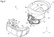
- FIG. 3 is an exploded perspective view of the head mounted display.
- the X-Y-Z coordinate system illustrated in the figures is to facilitate understanding of the embodiment, and does not limit the embodiment.
- the X-axis direction is the front-rear direction of the user who wears and uses the head mounted display
- the Y-axis direction is a right-left direction
- the Z-axis direction is an up-down direction.
- a head mounted display 10 generally includes: a headgear 16 having an attachment 12 that comes into close contact with the face of the user and a fixture 14 to be used for fixing the attachment 12 to the head of the user; and a display unit 18 that is detachable from the attachment 12 of the headgear 16.
- the attachment 12 of the headgear 16 functions as a bracket to be used for attaching the display unit 18 to the head of the user.
- FIG. 4 is a perspective view of the display unit and the attachment.
- FIG. 5 is a side view of the display unit and the attachment.
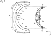
- FIG. 6 is a top view of the display unit and the attachment.
- the attachment 12 of the headgear 16 is a device that comes into close contact with the face of the user, particularly the periphery of the eyes, in a manner such that the user can see at least the front.
- the attachment 12 is in the shape of goggles in which a through hole 12a is formed in front of each of the eyes of the user.
- the attachment 12 is prepared from a cleanable material for a reason described later.
- the attachment 12 includes a nose pad 12b to be placed on the nose of the user in order to achieve positioning with respect to the face of the user. The nose pad 12b positions the attachment 12 with respect to the face of the user in the right-left direction (Y-axis direction) and the up-down direction (Z-axis direction).
- the attachment 12 includes, on the front side, a convex portion 12c that curves convexly toward the front of the user as viewed in the up-down direction (Z-axis direction) of the user as illustrated in FIG. 6 .
- the convex portion 12c of the attachment 12 has an arc shape. The reason of providing such a convex portion will be described later.
- the fixture 14 of the headgear 16 is a device that is attached to the attachment 12 and is used for fixing the attachment 12 to the head of the user while maintaining the close contact with the face of the user.
- the fixture 14 is composed of a first stretchable belt 14a that extends from one end toward the other end in the right-left direction (Y-axis direction) of the attachment 12, and a second stretchable belt 14b that extends from an upper end of the attachment 12 toward a central part of the first belt 14a.
- the fixture 14 is also prepared from a cleanable material as with the attachment 12 for a reason described later. With such a fixture 14, the attachment 12 is fixed to the head of the user in close contact with the face of the user.
- the head mounted display 10 is used for an attraction in which the head of the user repeatedly moves up and down, for example, in a case where the head mounted display 10 is worn by a user who gets on a moving casing such as a roller coaster, it is to be noted that the headgear 16 of the head mounted display 10 preferably includes a head pad unit 20 as in the present embodiment.
- the head pad unit 20 includes a front pad 20a that abuts on the forehead of the user and a rear pad 20b that abuts on the occipital region of the user, and the rear pad 20b is configured to be able to get close to and away from the front pad 20a.
- the front pad 20a is attached to the attachment 12 so as to be rotatable.
- the head pad unit 20 is attached so as to be rotatable with respect to a support shaft 12d that is provided at the attachment 12 and extends in the right-left direction (Y-axis direction).
- the head pad unit 20 is also prepared from a cleanable material as with the attachment 12 and the fixture 14.
- the display unit 18 is substantially a main body of the head mounted display 10, and includes a casing 18a that is detachable from the attachment 12 of the headgear 16. Moreover, as illustrated in FIG. 2 , the display unit 18 has, in the casing 18a, a video display unit 18b such as a liquid crystal display that displays video. Moreover, the display unit 18 includes a lens (not shown) to be disposed between the video display unit 18b and the attachment 12. When the display unit 18 is attached to the attachment 12, the lens and the video display unit 18b are disposed in front of the eyes of the user wearing the attachment 12. This provides the user with video displayed on the video display unit 18b via the lens.
- the casing 18a of the display unit 18 has a concave portion 18c that engages with the convex portion 12c of the attachment 12 on the rear side, that is, on the side of the attachment 12c as viewed in the up-down direction (Z-axis direction) of the user as illustrated in FIG. 6 .
- the attachment/detachment direction of the display unit 18 to/from the attachment 12 that is, the engagement direction is limited to the front-rear direction of the user. That is, the display cannot be attached to or detached from the attachment 12 in the right-left direction of the user.
- the reason of limiting the attachment/detachment direction of the display unit 18 to/from the attachment 12 to the front-rear direction of the user as described above and the effect thereof will be described later.
- the display unit 18 includes a pair of side guide portions 18d that guide the display unit 18 itself in the front-rear direction (X-axis direction) of the user when the display unit 18 is attached to and detached from the attachment 12 as illustrated in FIG. 6 .
- the pair of side guide portions 18d are disposed at both ends of the concave portion 18c of the display unit 18.
- the pair of side guide portions 18d guide the display unit 18 in the front-rear direction while positioning the display unit 18 with respect to the attachment 12 in the right-left direction.
- the attachment 12 exists between the pair of side guide portions 18d.
- Such a pair of side guide portions 18d also limit the attachment/detachment direction of the display unit 18 to/from the attachment 12 to the front-rear direction of the user.
- the head mounted display 10 has a lock mechanism 22 that fixes the display unit 18 to the attachment 12 in a manner such that the fixing can be released.
- the lock mechanism 22 is provided at a central part of the display unit 18 in the right-left direction (Y-axis direction).
- the lock mechanism 22 includes a pair of clamp arms 22a and 22b that sandwich the attachment 12 in the up-down direction (Z-axis direction) of the user.
- one clamp arm 22a is provided at an upper portion of the display unit 18, and the other clamp arm 22b is provided at a lower portion of the display unit 18.
- each of the clamp arms 22a and 22b includes a slip stopper pad 22c that has a tip configured to come into contact with the display unit 18 and is prepared from an elastic material such as rubber, for example.
- the clamp arms 22a and 22b of the lock mechanism 22 are each biased by a biasing member such as a spring (not shown) so that the attachment 12 is sandwiched in the up-down direction (Z-axis direction), that is, the tips (i.e., slip stopper pads 22c) of the clamp arms get close to each other.
- the display unit 18 is provided with unlock buttons 22d and 22e to be used for turning the clamp arms 22a and 22b so that the tips of the clamp arms 22a and 22b are separated from each other (two-dot chain line) against the biasing. Pressing the unlock button 22d turns one clamp arm 22a to tilt forward, and pressing the unlock button 22e turns the other clamp arm 22b to tilt forward, so that the tips of the clamp arms move away from each other.
- the attachment 12 is provided with an upper contact surface 12f and a lower contact surface 12g that come into surface contact with the tips (i.e., slip stopper pads 22c) of the clamp arms 22a and 22b.
- the upper contact surface 12f and the lower contact surface 12g are provided on opposite sides from each other in the up-down direction (Z-axis direction).
- the upper contact surface 12f and the lower contact surface 12g are not parallel to each other, and one is tilted with respect to the other so that a plane including the upper contact surface 12f and a plane including the lower contact surface 12g intersect with each other in front of the attachment 12.
- the display unit 18 is moved toward the attachment 12 in the front-rear direction (X-axis direction) of the user. This pushes the attachment 12 into between the tips of the pair of clamp arms 22a and 22b of the lock mechanism 22.
- the display unit 18 comes into contact with the attachment 12, and moreover, the attachment 12 is sandwiched by the pair of clamp arms 22a and 22b in the front-rear direction (Z-axis direction).
- the display unit 18 is fixed to the attachment 12.
- the pair of clamp arms 22a and 22b can release the attachment 12, so that the display unit 18 can be detached from the attachment 12.
- the display unit 18 can be firmly fixed to the attachment 12 fixed to the head of the user that repeatedly moves up and down during the attraction. That is, the display unit 18 is suppressed from moving up and down with respect to the attachment 12.
- the head mounted display 10 has a notification unit 24 that gives notification of completion of fixing the display unit 18 to the attachment 12 by the lock mechanism 22.
- the head mounted display 10 has a light emitting unit 24 such as an LED provided on an upper surface of the display unit 18 as the notification unit 24.
- the light emitting unit 24 emits, for example, green light when the fixing of the display unit 18 to the attachment 12 by the lock mechanism 22 is completed. This notifies a third party other than the user wearing the head mounted display 10, for example, an operator of the attraction that uses the head mounted display 10, of the completion of fixing the display unit 18. As a result, the operator can start the attraction for the user wearing the head mounted display 10.
- the completion of fixing the display unit 18 to the attachment 12 may be detected, for example, by pressing a detection switch of the display unit 18 with a protrusion projecting forward from the attachment 12.
- an integrated circuit (IC) and a plurality of contact electrodes connected to the IC are provided in the attachment 12, and a plurality of terminals that come into contact with the plurality of contact electrodes are provided in the display unit 18.
- the display unit 18 may transmit a signal via a terminal and receive a signal corresponding to the signal from the IC so as to detect the completion of fixing the display unit 18 to the attachment 12. This completion of fixing is variously changed according to the usage pattern of the head mounted display 10.
- the light emission of the light emitting unit 24 is invisible to the user because the light emission is to notify a third party other than the user wearing the head mounted display 10 of the completion of fixing the display unit 18 to the attachment 12. The user may be notified of the completion of fixing the display unit 18 via the video display unit 18b of the display unit 18.
- the display unit 18 that is substantially a main body of the head mounted display 10, and the headgear 16 (attachment 12, fixture 14, and head pad unit 20) that is a part of the head mounted display 10 to come into contact with the user are separable from each other.
- the display unit 18, that is, the head mounted display 10 can be continuously used by using some headgears 16 while other headgears 16 are cleaned.
- the display unit 18 can be attached to the attachment 12 of the headgear 16 worn by a user who is going to experience the attraction. For example, a user wearing a headgear 16 gets on an attraction vehicle, and the display unit 18 connected to the vehicle via a signal line can be attached to the attachment 12 of the user who has got on the vehicle.
- the user in the case of a head mounted display in which a display unit is undetachable, it is difficult for the user to check whether the head mounted display is normally worn or not, since the head mounted display covers the eyes of the user. Therefore, in some cases, the operator needs to make the check. Moreover, it may be necessary for the operator to assist some users in wearing the head mounted display. On the other hand, in the case of the present embodiment, the user can normally and easily wear the headgear 16 while checking with the eyes of the user and, in some cases, by using a mirror.
- the attachment 12 and the display unit 18 are configured to engage with each other in the front-rear direction (X-axis direction) of the user. This allows the user wearing the headgear 16 to easily attach the display unit 18 to the attachment 12 by disposing the display unit 18 in front and bringing the display unit 18 closer to the face of the user. In contrast, in a case where the display unit 18 engages with the attachment 12 in the right-left direction (Y-axis direction) or the up-down direction (Z-axis direction) of the user, the user needs to move the display unit 18 outside the field of view toward the attachment 12.
- the attachment 12 of the headgear 16 is in the shape of goggles, the user can intuitively position the attachment 12 with respect to the face of the user in a short time without worrying about how to wear the attachment. As a result, the wearing time of the head mounted display 10 is shortened, which increases the operating rate.
- the light emitting unit 24 gives notification of the completion of fixing the display unit 18 to the attachment 12. Accordingly, the operator can check the completion of fixing the display unit 18 to each of the plurality of users in a short time. This allows the operator to start the attraction immediately, which increases the operating rate of a head mounted display.
- fixing of the display unit 18 to the attachment 12 is achieved by the pair of clamp arms 22a and 22b of the lock mechanism 22 sandwiching the attachment 12 as illustrated in FIG. 2 .
- fixing the display unit to the attachment is not limited to this.
- the attachment may include a metal portion, and an electromagnet magnetically connected to the metal portion may be provided in the display unit.
- the display unit can be fixed to the attachment when the operator of the attraction turns on electricity of the electromagnet or when electricity of the electromagnet is automatically turned on immediately before the start of the attraction.
- the lock mechanism 22 is provided in the display unit 18 as illustrated in FIG. 3 .
- a lock mechanism may be provided in the attachment of the headgear.
- the light emission of the light emitting unit 24 gives notification of the completion of fixing the display unit 18 to the attachment 12.
- notification of the completion of fixing is not limited to this.
- the display unit 18 may transmit a fixing completion signal to a manual operating device of the attraction to be used by the operator to execute the start of the attraction.
- engagement between the attachment 12 and the display unit 18 in the front-rear direction (X-axis direction) of the user means engagement necessary for relatively moving the display unit 18 in the front-rear direction toward the attachment 12 so that the head mounted display 10 is brought into a final usable form. Accordingly, a case where the attachment 12 and the display unit 18 do not come into contact with each other in the front-rear direction is also included. For example, a case where an engagement pin that is provided in one of the attachment or the display and extends in the front-rear direction of the user, and an engagement hole that is provided in the other and penetrates in the front-rear direction engage with each other is also included.
- a head mounted display includes: a headgear having an attachment that comes into close contact with the face of the user in a manner such that the user can see at least the front and a fixture that is attached to the attachment and is used for fixing the attachment to the head of the user while maintaining the close contact with the face of the user; a display unit that has a video display unit configured to display video and is detachable from the attachment; and a lock mechanism that is provided in at least one of the attachment or the display unit, and fixes the display unit to the attachment in a manner such that the fixing can be released, in which the attachment and the display unit are configured to engage with each other in the front-rear direction of the user.
- components described in the accompanying drawings and the detailed description may include not only components essential for solving the problems, but also components not essential for solving the problems in order to illustrate the above technique. Therefore, it should not be immediately recognized that these non-essential components are essential even though those non-essential components are described in the accompanying drawings or the detailed description.
- the present disclosure is applicable to a head mounted display.
Landscapes
- Physics & Mathematics (AREA)
- General Physics & Mathematics (AREA)
- Optics & Photonics (AREA)
- Engineering & Computer Science (AREA)
- Multimedia (AREA)
- Signal Processing (AREA)
- Theoretical Computer Science (AREA)
- Devices For Indicating Variable Information By Combining Individual Elements (AREA)
Applications Claiming Priority (2)
| Application Number | Priority Date | Filing Date | Title |
|---|---|---|---|
| JP2019061678 | 2019-03-27 | ||
| PCT/JP2020/008121 WO2020195521A1 (ja) | 2019-03-27 | 2020-02-27 | ヘッドマウントディスプレイ |
Publications (3)
| Publication Number | Publication Date |
|---|---|
| EP3951752A1 EP3951752A1 (en) | 2022-02-09 |
| EP3951752A4 EP3951752A4 (en) | 2022-05-18 |
| EP3951752B1 true EP3951752B1 (en) | 2025-02-12 |
Family
ID=72609302
Family Applications (1)
| Application Number | Title | Priority Date | Filing Date |
|---|---|---|---|
| EP20777939.8A Active EP3951752B1 (en) | 2019-03-27 | 2020-02-27 | Head-mounted display |
Country Status (5)
| Country | Link |
|---|---|
| US (1) | US11668945B2 (https=) |
| EP (1) | EP3951752B1 (https=) |
| JP (1) | JP7462278B2 (https=) |
| CN (1) | CN112602136B (https=) |
| WO (1) | WO2020195521A1 (https=) |
Families Citing this family (4)
| Publication number | Priority date | Publication date | Assignee | Title |
|---|---|---|---|---|
| CN110716308B (zh) * | 2019-09-06 | 2024-07-16 | 华为技术有限公司 | 面罩及头戴式显示设备 |
| US12379604B2 (en) * | 2020-07-24 | 2025-08-05 | Universal City Studios Llc | Electromagnetic coupling systems and methods for visualization device |
| CN114637117A (zh) * | 2022-03-31 | 2022-06-17 | 苏州萤火空间科技有限公司 | 一种头戴式显示设备 |
| CN120266470A (zh) * | 2022-12-15 | 2025-07-04 | 株式会社半导体能源研究所 | 电子设备 |
Family Cites Families (23)
| Publication number | Priority date | Publication date | Assignee | Title |
|---|---|---|---|---|
| JP3352210B2 (ja) | 1994-03-10 | 2002-12-03 | オリンパス光学工業株式会社 | 頭部装着型映像表示装置 |
| CN100544414C (zh) * | 2003-12-26 | 2009-09-23 | 株式会社尼康 | 可佩戴显示单元、耳机和设有它们的系统 |
| JP4985248B2 (ja) * | 2007-09-05 | 2012-07-25 | コニカミノルタホールディングス株式会社 | 映像表示ユニットおよび面体ユニット |
| US8323216B2 (en) * | 2009-09-29 | 2012-12-04 | William Fabian | System and method for applied kinesiology feedback |
| CN102436064B (zh) * | 2010-09-29 | 2016-02-24 | 奥林巴斯株式会社 | 头戴式显示器 |
| EP2761362A2 (en) | 2011-09-26 | 2014-08-06 | Microsoft Corporation | Video display modification based on sensor input for a see-through near-to-eye display |
| JP5923926B2 (ja) * | 2011-10-24 | 2016-05-25 | ソニー株式会社 | ヘッド・マウント・ディスプレイ及びヘッド・マウント・ディスプレイの制御方法 |
| JP6099348B2 (ja) * | 2012-10-10 | 2017-03-22 | オリンパス株式会社 | 頭部装着型表示装置、ロック解除処理システム、プログラム及びロック解除の制御方法 |
| GB2499102B (en) * | 2013-01-11 | 2013-12-25 | Mvr Global Ltd | Head-mounted display device |
| JP6206099B2 (ja) * | 2013-11-05 | 2017-10-04 | セイコーエプソン株式会社 | 画像表示システム、画像表示システムを制御する方法、および、頭部装着型表示装置 |
| US20160011423A1 (en) * | 2014-03-10 | 2016-01-14 | Ion Virtual Technology Corporation | Method and system for reducing motion blur when experiencing virtual or augmented reality environments |
| CN204331156U (zh) * | 2014-09-16 | 2015-05-13 | 赵山山 | 一种手机3d立体眼镜中的视距调节装置 |
| US10085004B2 (en) * | 2015-06-15 | 2018-09-25 | Oculus Vr, Llc | Dual-screen head-mounted displays |
| KR102415898B1 (ko) * | 2015-10-21 | 2022-07-01 | 삼성전자 주식회사 | 외부장치 연결에 따른 기능 제어 방법 및 장치 |
| CN106125918A (zh) * | 2016-06-18 | 2016-11-16 | 深圳晨芯时代科技有限公司 | 一种虚拟现实装置和虚拟现实分享系统 |
| US11686946B2 (en) | 2016-09-19 | 2023-06-27 | Razer (Asia-Pacific) Pte. Ltd. | Head-mounted display for public use |
| JP6912889B2 (ja) * | 2017-01-12 | 2021-08-04 | 任天堂株式会社 | ゲームシステムおよびゲームコントローラ |
| CN108459413B (zh) * | 2017-02-22 | 2021-10-08 | 宏达国际电子股份有限公司 | 头戴式显示装置 |
| US10366347B2 (en) * | 2017-06-02 | 2019-07-30 | At&T Intellectual Property I, L.P. | Methods, systems and devices for monitoring and controlling media content using machine learning |
| US10578869B2 (en) | 2017-07-24 | 2020-03-03 | Mentor Acquisition One, Llc | See-through computer display systems with adjustable zoom cameras |
| JP2019036888A (ja) | 2017-08-18 | 2019-03-07 | セイコーエプソン株式会社 | 頭部装着型画像表示装置及び面体ユニット |
| JP6845111B2 (ja) | 2017-08-23 | 2021-03-17 | 株式会社ソニー・インタラクティブエンタテインメント | 情報処理装置および画像表示方法 |
| US10838216B2 (en) * | 2018-01-19 | 2020-11-17 | Universal City Studios Llc | Virtual reality/augmented reality rapid deployment system |
-
2020
- 2020-02-27 JP JP2021508854A patent/JP7462278B2/ja active Active
- 2020-02-27 CN CN202080004593.2A patent/CN112602136B/zh active Active
- 2020-02-27 EP EP20777939.8A patent/EP3951752B1/en active Active
- 2020-02-27 WO PCT/JP2020/008121 patent/WO2020195521A1/ja not_active Ceased
- 2020-02-27 US US17/269,782 patent/US11668945B2/en active Active
Also Published As
| Publication number | Publication date |
|---|---|
| WO2020195521A1 (ja) | 2020-10-01 |
| CN112602136B (zh) | 2023-12-15 |
| JP7462278B2 (ja) | 2024-04-05 |
| EP3951752A4 (en) | 2022-05-18 |
| US11668945B2 (en) | 2023-06-06 |
| JPWO2020195521A1 (https=) | 2020-10-01 |
| US20210318545A1 (en) | 2021-10-14 |
| EP3951752A1 (en) | 2022-02-09 |
| CN112602136A (zh) | 2021-04-02 |
Similar Documents
| Publication | Publication Date | Title |
|---|---|---|
| EP3951752B1 (en) | Head-mounted display | |
| JP7273928B2 (ja) | 頭部装着型コンピュータのための調節可能鼻用ブリッジアセンブリ | |
| JP6524482B2 (ja) | 有害閃光遮断と防眩用の電子保護眼鏡 | |
| US11144125B2 (en) | Hands-free switch system | |
| CN216221898U (zh) | 头戴式系统、装置和接口单元以及免手式开关系统 | |
| JP6155614B2 (ja) | 頭部装着型表示装置および頭部装着型表示装置の制御方法 | |
| KR20160125475A (ko) | 안경형 정보 단말, 정보 처리 장치, 컴퓨터 프로그램 및 기록 매체 | |
| JP2018142857A (ja) | 頭部装着型表示装置、プログラム、及び頭部装着型表示装置の制御方法 | |
| US20210041723A1 (en) | Eyewear system | |
| JP4926302B1 (ja) | 電子機器、制御方法及びプログラム | |
| US20230127100A1 (en) | Clench activated switch system | |
| JP2004233776A (ja) | ヘッドマウントディスプレイ | |
| KR20200137234A (ko) | 초소형 카메라 렌즈 및 적외선 플래시를 장착한 도촬기기 탐지 장치 | |
| JP2017120336A (ja) | 頭部装着型画像表示装置 | |
| JP2013114124A (ja) | 画像表示装置、画像表示装置における電源制御方法および画像表示装置における電源制御プログラム | |
| TW201839466A (zh) | 穿戴式裝置的保持具、及具備該保持具的顏面或頭部裝設具 | |
| KR20210111616A (ko) | 가상 이미지를 제공하는 웨어러블 전자 장치 | |
| JP4973423B2 (ja) | 頭部装着型画像表示装置 | |
| JP3121579U (ja) | 頭部装着型表示装置 | |
| CN223513408U (zh) | 护目镜框及护目镜 | |
| JP4517904B2 (ja) | ヘッドマウントディスプレイ | |
| CN114583770B (zh) | 充电座 | |
| JP3227691U (ja) | 居眠り防止用眼鏡 | |
| JP3056072U (ja) | ヘッドマウントディスプレイ装置 | |
| JPH10123456A (ja) | ヘッドマウントディスプレイ装置 |
Legal Events
| Date | Code | Title | Description |
|---|---|---|---|
| STAA | Information on the status of an ep patent application or granted ep patent |
Free format text: STATUS: THE INTERNATIONAL PUBLICATION HAS BEEN MADE |
|
| PUAI | Public reference made under article 153(3) epc to a published international application that has entered the european phase |
Free format text: ORIGINAL CODE: 0009012 |
|
| STAA | Information on the status of an ep patent application or granted ep patent |
Free format text: STATUS: REQUEST FOR EXAMINATION WAS MADE |
|
| 17P | Request for examination filed |
Effective date: 20210223 |
|
| AK | Designated contracting states |
Kind code of ref document: A1 Designated state(s): AL AT BE BG CH CY CZ DE DK EE ES FI FR GB GR HR HU IE IS IT LI LT LU LV MC MK MT NL NO PL PT RO RS SE SI SK SM TR |
|
| A4 | Supplementary search report drawn up and despatched |
Effective date: 20220420 |
|
| RIC1 | Information provided on ipc code assigned before grant |
Ipc: G02B 27/02 20060101ALI20220412BHEP Ipc: H04N 5/64 20060101ALI20220412BHEP Ipc: G09F 9/00 20060101AFI20220412BHEP |
|
| DAV | Request for validation of the european patent (deleted) | ||
| DAX | Request for extension of the european patent (deleted) | ||
| GRAP | Despatch of communication of intention to grant a patent |
Free format text: ORIGINAL CODE: EPIDOSNIGR1 |
|
| STAA | Information on the status of an ep patent application or granted ep patent |
Free format text: STATUS: GRANT OF PATENT IS INTENDED |
|
| INTG | Intention to grant announced |
Effective date: 20241008 |
|
| GRAS | Grant fee paid |
Free format text: ORIGINAL CODE: EPIDOSNIGR3 |
|
| GRAA | (expected) grant |
Free format text: ORIGINAL CODE: 0009210 |
|
| STAA | Information on the status of an ep patent application or granted ep patent |
Free format text: STATUS: THE PATENT HAS BEEN GRANTED |
|
| AK | Designated contracting states |
Kind code of ref document: B1 Designated state(s): AL AT BE BG CH CY CZ DE DK EE ES FI FR GB GR HR HU IE IS IT LI LT LU LV MC MK MT NL NO PL PT RO RS SE SI SK SM TR |
|
| REG | Reference to a national code |
Ref country code: GB Ref legal event code: FG4D |
|
| REG | Reference to a national code |
Ref country code: CH Ref legal event code: EP |
|
| REG | Reference to a national code |
Ref country code: DE Ref legal event code: R096 Ref document number: 602020045963 Country of ref document: DE |
|
| REG | Reference to a national code |
Ref country code: IE Ref legal event code: FG4D |
|
| REG | Reference to a national code |
Ref country code: NL Ref legal event code: MP Effective date: 20250212 |
|
| PG25 | Lapsed in a contracting state [announced via postgrant information from national office to epo] |
Ref country code: RS Free format text: LAPSE BECAUSE OF FAILURE TO SUBMIT A TRANSLATION OF THE DESCRIPTION OR TO PAY THE FEE WITHIN THE PRESCRIBED TIME-LIMIT Effective date: 20250512 |
|
| PG25 | Lapsed in a contracting state [announced via postgrant information from national office to epo] |
Ref country code: FI Free format text: LAPSE BECAUSE OF FAILURE TO SUBMIT A TRANSLATION OF THE DESCRIPTION OR TO PAY THE FEE WITHIN THE PRESCRIBED TIME-LIMIT Effective date: 20250212 |
|
| PG25 | Lapsed in a contracting state [announced via postgrant information from national office to epo] |
Ref country code: PL Free format text: LAPSE BECAUSE OF FAILURE TO SUBMIT A TRANSLATION OF THE DESCRIPTION OR TO PAY THE FEE WITHIN THE PRESCRIBED TIME-LIMIT Effective date: 20250212 |
|
| PG25 | Lapsed in a contracting state [announced via postgrant information from national office to epo] |
Ref country code: ES Free format text: LAPSE BECAUSE OF FAILURE TO SUBMIT A TRANSLATION OF THE DESCRIPTION OR TO PAY THE FEE WITHIN THE PRESCRIBED TIME-LIMIT Effective date: 20250212 |
|
| REG | Reference to a national code |
Ref country code: LT Ref legal event code: MG9D |
|
| PG25 | Lapsed in a contracting state [announced via postgrant information from national office to epo] |
Ref country code: IS Free format text: LAPSE BECAUSE OF FAILURE TO SUBMIT A TRANSLATION OF THE DESCRIPTION OR TO PAY THE FEE WITHIN THE PRESCRIBED TIME-LIMIT Effective date: 20250612 Ref country code: NO Free format text: LAPSE BECAUSE OF FAILURE TO SUBMIT A TRANSLATION OF THE DESCRIPTION OR TO PAY THE FEE WITHIN THE PRESCRIBED TIME-LIMIT Effective date: 20250512 |
|
| PG25 | Lapsed in a contracting state [announced via postgrant information from national office to epo] |
Ref country code: NL Free format text: LAPSE BECAUSE OF FAILURE TO SUBMIT A TRANSLATION OF THE DESCRIPTION OR TO PAY THE FEE WITHIN THE PRESCRIBED TIME-LIMIT Effective date: 20250212 |
|
| PG25 | Lapsed in a contracting state [announced via postgrant information from national office to epo] |
Ref country code: HR Free format text: LAPSE BECAUSE OF FAILURE TO SUBMIT A TRANSLATION OF THE DESCRIPTION OR TO PAY THE FEE WITHIN THE PRESCRIBED TIME-LIMIT Effective date: 20250212 |
|
| PG25 | Lapsed in a contracting state [announced via postgrant information from national office to epo] |
Ref country code: PT Free format text: LAPSE BECAUSE OF FAILURE TO SUBMIT A TRANSLATION OF THE DESCRIPTION OR TO PAY THE FEE WITHIN THE PRESCRIBED TIME-LIMIT Effective date: 20250612 Ref country code: LV Free format text: LAPSE BECAUSE OF FAILURE TO SUBMIT A TRANSLATION OF THE DESCRIPTION OR TO PAY THE FEE WITHIN THE PRESCRIBED TIME-LIMIT Effective date: 20250212 |
|
| PG25 | Lapsed in a contracting state [announced via postgrant information from national office to epo] |
Ref country code: GR Free format text: LAPSE BECAUSE OF FAILURE TO SUBMIT A TRANSLATION OF THE DESCRIPTION OR TO PAY THE FEE WITHIN THE PRESCRIBED TIME-LIMIT Effective date: 20250513 Ref country code: BG Free format text: LAPSE BECAUSE OF FAILURE TO SUBMIT A TRANSLATION OF THE DESCRIPTION OR TO PAY THE FEE WITHIN THE PRESCRIBED TIME-LIMIT Effective date: 20250212 |
|
| REG | Reference to a national code |
Ref country code: AT Ref legal event code: MK05 Ref document number: 1766857 Country of ref document: AT Kind code of ref document: T Effective date: 20250212 |
|
| PG25 | Lapsed in a contracting state [announced via postgrant information from national office to epo] |
Ref country code: SE Free format text: LAPSE BECAUSE OF FAILURE TO SUBMIT A TRANSLATION OF THE DESCRIPTION OR TO PAY THE FEE WITHIN THE PRESCRIBED TIME-LIMIT Effective date: 20250212 |
|
| REG | Reference to a national code |
Ref country code: CH Ref legal event code: PL |
|
| PG25 | Lapsed in a contracting state [announced via postgrant information from national office to epo] |
Ref country code: SM Free format text: LAPSE BECAUSE OF FAILURE TO SUBMIT A TRANSLATION OF THE DESCRIPTION OR TO PAY THE FEE WITHIN THE PRESCRIBED TIME-LIMIT Effective date: 20250212 |
|
| PG25 | Lapsed in a contracting state [announced via postgrant information from national office to epo] |
Ref country code: DK Free format text: LAPSE BECAUSE OF FAILURE TO SUBMIT A TRANSLATION OF THE DESCRIPTION OR TO PAY THE FEE WITHIN THE PRESCRIBED TIME-LIMIT Effective date: 20250212 |
|
| PG25 | Lapsed in a contracting state [announced via postgrant information from national office to epo] |
Ref country code: IT Free format text: LAPSE BECAUSE OF FAILURE TO SUBMIT A TRANSLATION OF THE DESCRIPTION OR TO PAY THE FEE WITHIN THE PRESCRIBED TIME-LIMIT Effective date: 20250212 Ref country code: LU Free format text: LAPSE BECAUSE OF NON-PAYMENT OF DUE FEES Effective date: 20250227 |
|
| PG25 | Lapsed in a contracting state [announced via postgrant information from national office to epo] |
Ref country code: AT Free format text: LAPSE BECAUSE OF FAILURE TO SUBMIT A TRANSLATION OF THE DESCRIPTION OR TO PAY THE FEE WITHIN THE PRESCRIBED TIME-LIMIT Effective date: 20250212 |
|
| PG25 | Lapsed in a contracting state [announced via postgrant information from national office to epo] |
Ref country code: CH Free format text: LAPSE BECAUSE OF NON-PAYMENT OF DUE FEES Effective date: 20250228 |
|
| PG25 | Lapsed in a contracting state [announced via postgrant information from national office to epo] |
Ref country code: EE Free format text: LAPSE BECAUSE OF FAILURE TO SUBMIT A TRANSLATION OF THE DESCRIPTION OR TO PAY THE FEE WITHIN THE PRESCRIBED TIME-LIMIT Effective date: 20250212 Ref country code: CZ Free format text: LAPSE BECAUSE OF FAILURE TO SUBMIT A TRANSLATION OF THE DESCRIPTION OR TO PAY THE FEE WITHIN THE PRESCRIBED TIME-LIMIT Effective date: 20250212 |
|
| PG25 | Lapsed in a contracting state [announced via postgrant information from national office to epo] |
Ref country code: RO Free format text: LAPSE BECAUSE OF FAILURE TO SUBMIT A TRANSLATION OF THE DESCRIPTION OR TO PAY THE FEE WITHIN THE PRESCRIBED TIME-LIMIT Effective date: 20250212 |
|
| PG25 | Lapsed in a contracting state [announced via postgrant information from national office to epo] |
Ref country code: SK Free format text: LAPSE BECAUSE OF FAILURE TO SUBMIT A TRANSLATION OF THE DESCRIPTION OR TO PAY THE FEE WITHIN THE PRESCRIBED TIME-LIMIT Effective date: 20250212 |
|
| REG | Reference to a national code |
Ref country code: DE Ref legal event code: R097 Ref document number: 602020045963 Country of ref document: DE |
|
| REG | Reference to a national code |
Ref country code: BE Ref legal event code: MM Effective date: 20250228 |
|
| PLBE | No opposition filed within time limit |
Free format text: ORIGINAL CODE: 0009261 |
|
| STAA | Information on the status of an ep patent application or granted ep patent |
Free format text: STATUS: NO OPPOSITION FILED WITHIN TIME LIMIT |
|
| PG25 | Lapsed in a contracting state [announced via postgrant information from national office to epo] |
Ref country code: MC Free format text: LAPSE BECAUSE OF FAILURE TO SUBMIT A TRANSLATION OF THE DESCRIPTION OR TO PAY THE FEE WITHIN THE PRESCRIBED TIME-LIMIT Effective date: 20250212 |
|
| PG25 | Lapsed in a contracting state [announced via postgrant information from national office to epo] |
Ref country code: BE Free format text: LAPSE BECAUSE OF NON-PAYMENT OF DUE FEES Effective date: 20250228 |
|
| PG25 | Lapsed in a contracting state [announced via postgrant information from national office to epo] |
Ref country code: IE Free format text: LAPSE BECAUSE OF NON-PAYMENT OF DUE FEES Effective date: 20250227 |
|
| 26N | No opposition filed |
Effective date: 20251113 |
|
| PGFP | Annual fee paid to national office [announced via postgrant information from national office to epo] |
Ref country code: GB Payment date: 20260220 Year of fee payment: 7 |
|
| PGFP | Annual fee paid to national office [announced via postgrant information from national office to epo] |
Ref country code: DE Payment date: 20260218 Year of fee payment: 7 |
|
| PGFP | Annual fee paid to national office [announced via postgrant information from national office to epo] |
Ref country code: FR Payment date: 20260219 Year of fee payment: 7 |