WO2020195418A1 - バタフライバルブ - Google Patents
バタフライバルブ Download PDFInfo
- Publication number
- WO2020195418A1 WO2020195418A1 PCT/JP2020/006985 JP2020006985W WO2020195418A1 WO 2020195418 A1 WO2020195418 A1 WO 2020195418A1 JP 2020006985 W JP2020006985 W JP 2020006985W WO 2020195418 A1 WO2020195418 A1 WO 2020195418A1
- Authority
- WO
- WIPO (PCT)
- Prior art keywords
- butterfly valve
- rod
- center
- axis
- gravity
- Prior art date
- Legal status (The legal status is an assumption and is not a legal conclusion. Google has not performed a legal analysis and makes no representation as to the accuracy of the status listed.)
- Ceased
Links
Images




Classifications
-
- F—MECHANICAL ENGINEERING; LIGHTING; HEATING; WEAPONS; BLASTING
- F16—ENGINEERING ELEMENTS AND UNITS; GENERAL MEASURES FOR PRODUCING AND MAINTAINING EFFECTIVE FUNCTIONING OF MACHINES OR INSTALLATIONS; THERMAL INSULATION IN GENERAL
- F16K—VALVES; TAPS; COCKS; ACTUATING-FLOATS; DEVICES FOR VENTING OR AERATING
- F16K1/00—Lift valves or globe valves, i.e. cut-off apparatus with closure members having at least a component of their opening and closing motion perpendicular to the closing faces
- F16K1/16—Lift valves or globe valves, i.e. cut-off apparatus with closure members having at least a component of their opening and closing motion perpendicular to the closing faces with pivoted closure-members
- F16K1/18—Lift valves or globe valves, i.e. cut-off apparatus with closure members having at least a component of their opening and closing motion perpendicular to the closing faces with pivoted closure-members with pivoted discs or flaps
- F16K1/22—Lift valves or globe valves, i.e. cut-off apparatus with closure members having at least a component of their opening and closing motion perpendicular to the closing faces with pivoted closure-members with pivoted discs or flaps with axis of rotation crossing the valve member, e.g. butterfly valves
-
- F—MECHANICAL ENGINEERING; LIGHTING; HEATING; WEAPONS; BLASTING
- F16—ENGINEERING ELEMENTS AND UNITS; GENERAL MEASURES FOR PRODUCING AND MAINTAINING EFFECTIVE FUNCTIONING OF MACHINES OR INSTALLATIONS; THERMAL INSULATION IN GENERAL
- F16K—VALVES; TAPS; COCKS; ACTUATING-FLOATS; DEVICES FOR VENTING OR AERATING
- F16K1/00—Lift valves or globe valves, i.e. cut-off apparatus with closure members having at least a component of their opening and closing motion perpendicular to the closing faces
- F16K1/24—Lift valves or globe valves, i.e. cut-off apparatus with closure members having at least a component of their opening and closing motion perpendicular to the closing faces with valve members that, on opening of the valve, are initially lifted from the seat and next are turned around an axis parallel to the seat
-
- F—MECHANICAL ENGINEERING; LIGHTING; HEATING; WEAPONS; BLASTING
- F16—ENGINEERING ELEMENTS AND UNITS; GENERAL MEASURES FOR PRODUCING AND MAINTAINING EFFECTIVE FUNCTIONING OF MACHINES OR INSTALLATIONS; THERMAL INSULATION IN GENERAL
- F16K—VALVES; TAPS; COCKS; ACTUATING-FLOATS; DEVICES FOR VENTING OR AERATING
- F16K1/00—Lift valves or globe valves, i.e. cut-off apparatus with closure members having at least a component of their opening and closing motion perpendicular to the closing faces
- F16K1/16—Lift valves or globe valves, i.e. cut-off apparatus with closure members having at least a component of their opening and closing motion perpendicular to the closing faces with pivoted closure-members
- F16K1/18—Lift valves or globe valves, i.e. cut-off apparatus with closure members having at least a component of their opening and closing motion perpendicular to the closing faces with pivoted closure-members with pivoted discs or flaps
- F16K1/22—Lift valves or globe valves, i.e. cut-off apparatus with closure members having at least a component of their opening and closing motion perpendicular to the closing faces with pivoted closure-members with pivoted discs or flaps with axis of rotation crossing the valve member, e.g. butterfly valves
- F16K1/221—Lift valves or globe valves, i.e. cut-off apparatus with closure members having at least a component of their opening and closing motion perpendicular to the closing faces with pivoted closure-members with pivoted discs or flaps with axis of rotation crossing the valve member, e.g. butterfly valves specially adapted operating means therefor
-
- F—MECHANICAL ENGINEERING; LIGHTING; HEATING; WEAPONS; BLASTING
- F16—ENGINEERING ELEMENTS AND UNITS; GENERAL MEASURES FOR PRODUCING AND MAINTAINING EFFECTIVE FUNCTIONING OF MACHINES OR INSTALLATIONS; THERMAL INSULATION IN GENERAL
- F16K—VALVES; TAPS; COCKS; ACTUATING-FLOATS; DEVICES FOR VENTING OR AERATING
- F16K1/00—Lift valves or globe valves, i.e. cut-off apparatus with closure members having at least a component of their opening and closing motion perpendicular to the closing faces
- F16K1/16—Lift valves or globe valves, i.e. cut-off apparatus with closure members having at least a component of their opening and closing motion perpendicular to the closing faces with pivoted closure-members
- F16K1/18—Lift valves or globe valves, i.e. cut-off apparatus with closure members having at least a component of their opening and closing motion perpendicular to the closing faces with pivoted closure-members with pivoted discs or flaps
- F16K1/22—Lift valves or globe valves, i.e. cut-off apparatus with closure members having at least a component of their opening and closing motion perpendicular to the closing faces with pivoted closure-members with pivoted discs or flaps with axis of rotation crossing the valve member, e.g. butterfly valves
- F16K1/224—Details of bearings for the axis of rotation
-
- F—MECHANICAL ENGINEERING; LIGHTING; HEATING; WEAPONS; BLASTING
- F16—ENGINEERING ELEMENTS AND UNITS; GENERAL MEASURES FOR PRODUCING AND MAINTAINING EFFECTIVE FUNCTIONING OF MACHINES OR INSTALLATIONS; THERMAL INSULATION IN GENERAL
- F16K—VALVES; TAPS; COCKS; ACTUATING-FLOATS; DEVICES FOR VENTING OR AERATING
- F16K31/00—Actuating devices; Operating means; Releasing devices
- F16K31/02—Actuating devices; Operating means; Releasing devices electric; magnetic
- F16K31/04—Actuating devices; Operating means; Releasing devices electric; magnetic using a motor
-
- F—MECHANICAL ENGINEERING; LIGHTING; HEATING; WEAPONS; BLASTING
- F16—ENGINEERING ELEMENTS AND UNITS; GENERAL MEASURES FOR PRODUCING AND MAINTAINING EFFECTIVE FUNCTIONING OF MACHINES OR INSTALLATIONS; THERMAL INSULATION IN GENERAL
- F16K—VALVES; TAPS; COCKS; ACTUATING-FLOATS; DEVICES FOR VENTING OR AERATING
- F16K31/00—Actuating devices; Operating means; Releasing devices
- F16K31/02—Actuating devices; Operating means; Releasing devices electric; magnetic
- F16K31/04—Actuating devices; Operating means; Releasing devices electric; magnetic using a motor
- F16K31/041—Actuating devices; Operating means; Releasing devices electric; magnetic using a motor for rotating valves
-
- F—MECHANICAL ENGINEERING; LIGHTING; HEATING; WEAPONS; BLASTING
- F16—ENGINEERING ELEMENTS AND UNITS; GENERAL MEASURES FOR PRODUCING AND MAINTAINING EFFECTIVE FUNCTIONING OF MACHINES OR INSTALLATIONS; THERMAL INSULATION IN GENERAL
- F16K—VALVES; TAPS; COCKS; ACTUATING-FLOATS; DEVICES FOR VENTING OR AERATING
- F16K37/00—Special means in or on valves or other cut-off apparatus for indicating or recording operation thereof, or for enabling an alarm to be given
- F16K37/0025—Electrical or magnetic means
-
- F—MECHANICAL ENGINEERING; LIGHTING; HEATING; WEAPONS; BLASTING
- F16—ENGINEERING ELEMENTS AND UNITS; GENERAL MEASURES FOR PRODUCING AND MAINTAINING EFFECTIVE FUNCTIONING OF MACHINES OR INSTALLATIONS; THERMAL INSULATION IN GENERAL
- F16K—VALVES; TAPS; COCKS; ACTUATING-FLOATS; DEVICES FOR VENTING OR AERATING
- F16K37/00—Special means in or on valves or other cut-off apparatus for indicating or recording operation thereof, or for enabling an alarm to be given
- F16K37/0025—Electrical or magnetic means
- F16K37/0041—Electrical or magnetic means for measuring valve parameters
-
- F—MECHANICAL ENGINEERING; LIGHTING; HEATING; WEAPONS; BLASTING
- F16—ENGINEERING ELEMENTS AND UNITS; GENERAL MEASURES FOR PRODUCING AND MAINTAINING EFFECTIVE FUNCTIONING OF MACHINES OR INSTALLATIONS; THERMAL INSULATION IN GENERAL
- F16K—VALVES; TAPS; COCKS; ACTUATING-FLOATS; DEVICES FOR VENTING OR AERATING
- F16K49/00—Means in or on valves for heating or cooling
-
- F—MECHANICAL ENGINEERING; LIGHTING; HEATING; WEAPONS; BLASTING
- F16—ENGINEERING ELEMENTS AND UNITS; GENERAL MEASURES FOR PRODUCING AND MAINTAINING EFFECTIVE FUNCTIONING OF MACHINES OR INSTALLATIONS; THERMAL INSULATION IN GENERAL
- F16K—VALVES; TAPS; COCKS; ACTUATING-FLOATS; DEVICES FOR VENTING OR AERATING
- F16K49/00—Means in or on valves for heating or cooling
- F16K49/002—Electric heating means
Definitions
- the present invention opens and closes a flow path by connecting to a motor, a flow path, a rod connected to the motor and arranged in a direction orthogonal to the flow path, and rotating the rod by the motor. It relates to a butterfly valve body and a butterfly valve having a butterfly valve body.
- a butterfly valve having a large flow path conductance is often arranged between the vacuum chamber and the vacuum pump as a vacuum pressure control device to control the vacuum pressure in the vacuum chamber.
- a butterfly valve is used in which a butterfly valve body coupled to a rod is brought into contact with and separated from an annular valve seat by rotating the rod with a motor.
- the butterfly valve body disclosed in Patent Document 1 is coupled to the rod in a state where the center point of the butterfly valve body is eccentric with respect to the rotation center axis of the rod. Therefore, the center of gravity of the butterfly valve body is not on the rotation center axis of the rod, and when the rod is rotated to open and close the flow path by the butterfly valve body, centrifugal force is generated, and the centrifugal force causes the rotation center axis of the rod to move. It will be shaken. If the rotation center axis of the rod is shaken, the load on the ball bearing that supports the rod becomes excessive, the ball bearing is damaged, and the butterfly valve body interferes with the inner wall of the flow path. There is a problem that the life is adversely affected.
- the speed of vacuum pressure control by the butterfly valve has also been increased, and the butterfly valve body is fully opened to fully closed.
- the time to (or from fully closed to fully open) is, for example, about 0.1 seconds, and the rotation speed is very fast. The faster the rotation speed, the more easily the rotation center axis of the rod is shaken due to the centrifugal force, and the above problem may become more remarkable.
- the present invention is for solving the above-mentioned problems, and it is possible to suppress the centrifugal force generated on the rod when the butterfly valve body is opened and closed, and to suppress the deviation of the rotation center axis of the rod, and the life is long. It is intended to provide a butterfly valve.
- the butterfly valve according to one aspect of the present invention has the following configuration.
- a motor, a flow path, a rod connected to the motor and arranged in a direction orthogonal to the flow path, and the rod are connected to the rod, and the rod is rotated by the motor to open and close the flow path.
- the butterfly valve having the butterfly valve body at least the combined center of gravity, which is the center of gravity of the coupling body including the rod and the butterfly valve body, is located on the axis of the rotation axis of the motor. And.
- any of the center of gravity of the constituent members which is the center of gravity of each constituent member constituting the coupled body, is placed on a virtual plane passing through the axis of the rotation axis.
- the distance between the center of gravity of the component and the axis placed in one area separated by the axis of the rotation axis is set as a positive value, and the center of gravity of the component and the axis placed in the other area are defined as positive values.
- the moment is calculated by multiplying the distance between the center of gravity of the component and the axis by the mass of each component, and the total value of the calculated moments is approximately 0. It is preferable that it is configured in.
- the coupling is formed by connecting the butterfly valve body to the rod by a fixture, and the combined weight center also considers the center of gravity of the fixture. It is preferable that there is.
- the fixture is either a screw and a washer or a rivet.
- the coupling body is formed by welding a butterfly valve body to a rod, and the beads generated by welding are removed.
- the motor is a direct drive motor.
- the rod is pivotally supported in a dual-holding state by two ball bearings arranged adjacent to each other in the axial direction of the rod and a bush.
- Each of the two ball bearings consists of an outer ring, an inner ring, and a rolling element arranged between the outer ring and the inner ring, and each of the two ball bearings is preloaded to form an outer ring and a rolling element.
- the virtual line connecting the contact point of the inner ring and the contact point of the rolling element has an angle with respect to the radial direction of the rod, so that the angle formed by each virtual line of the two ball bearings spreads toward the rod. It is preferable that it is arranged.
- the temperature of the valve body is based on the temperature sensor that measures the temperature of the valve body having a flow path inside and the measured value of the temperature sensor. It is preferable to provide a heater for adjusting the temperature and a thermostat for detecting an excessive temperature rise of the valve body.
- the butterfly valve of the present invention has the following actions and effects by having the above configuration.
- the combined weight center which is the center of gravity of the combined body of the rod and the butterfly valve body
- the rod is rotated by the motor.
- centrifugal force is less likely to work on the rod. If centrifugal force is less likely to act on the rod, it is possible to suppress the deviation of the rotation center axis of the rod. If the deflection of the rotation center axis can be suppressed, the load on the member (for example, a ball bearing) that supports the rod can be reduced, and the butterfly valve body can be prevented from interfering with the inner wall of the flow path. Life is also improved.
- all of the constituent member center of gravity which is the center of gravity of each constituent member constituting the combined body, are placed in a virtual plane passing on the axis of the rotation axis.
- the distance between the component center of gravity placed in one area separated by the axis and the axis is a positive value
- the distance between the component center of gravity placed in the other area and the axis is It is configured to be a negative value
- the moment obtained by multiplying the distance between the center of gravity of the component and the axis by the mass of each component is calculated, and the total value of the calculated moments is approximately 0. ing.
- the balance of the moments acting on the respective constituent members constituting the combined body is balanced on the axis, and the combined weight center of the combined body is located on the axis. Therefore, even if the rod is rotated by the motor, centrifugal force is less likely to act on the rod, and it is possible to suppress the deviation of the rotation center axis of the rod.
- the coupling is formed by connecting the butterfly valve body to the rod by a fixing tool such as a screw and a washer or a rivet, and the binding center of gravity is a fixing tool. Since the center of gravity of the rivet is also taken into consideration, the combined weight center of the combined body including the fixture is located on the axis of the rotation axis of the motor. Therefore, even if the rod is rotated by the motor, centrifugal force is less likely to act on the rod. If centrifugal force is less likely to act on the rod, it is possible to suppress the deviation of the rotation center axis of the rod.
- the coupling is formed by welding the butterfly valve body to the rod, and the bead generated by welding is removed. Therefore, the combined center of gravity is the bead generated by welding. It is determined only by the center of gravity of the rod and the center of gravity of the butterfly valve body, without being influenced by the center of gravity of the butterfly valve body.
- the motor that rotates the rod is a direct drive motor
- the rod can be rotated at high speed.
- a stepping motor has often been used for the butterfly valve.
- the time from fully open to fully closed (or from fully closed to fully open) of the butterfly valve body is, for example, about 0.5 seconds, which is the speed required by ALD, for example, 0.1 seconds. It was difficult to satisfy. Therefore, it was considered to increase the speed by using a direct drive motor, but by increasing the speed, the center axis of rotation of the rod tends to shake due to centrifugal force, and the load on the ball bearing that supports the rod becomes excessive.
- the rotation center axis of the rod is It is more stable and less likely to shake.
- the virtual line connecting the contact point between the outer ring and the rolling element and the contact point between the inner ring and the rolling element is configured to have an angle with respect to the radial direction of the rod. Since the angle formed by the virtual lines of each of the ball bearings is arranged so as to widen toward the rod, the internal clearance of the ball bearing that supports the rod is less likely to occur, and the rigidity is increased. When the rigidity of the ball bearing is increased, the vibration when the rod rotates is suppressed, and the deviation of the rotation center axis of the rod is suppressed.
- the temperature of the valve body can be adjusted by the temperature sensor and the heater. Further, since the thermostat can detect the excessive temperature rise of the valve body, the valve body is not excessively heated due to the runaway of the heater.
- the embodiment of the butterfly valve 1 of the present invention will be described in detail with reference to the drawings.
- the butterfly valve 1 is disposed on a pipe 34 connecting the vacuum chamber 32 and the vacuum pump 33 in the semiconductor manufacturing process, and controls the pressure of the vacuum chamber 32 in which gas is constantly supplied from the gas supply source 37. It is used as a control device (see FIG. 7).
- FIG. 1 is a cross-sectional view of the butterfly valve 1 according to the embodiment of the present invention in a direction parallel to the flow path 30.
- FIG. 2 is a side sectional view of the butterfly valve according to the embodiment of the present invention in a direction orthogonal to the flow path.
- the butterfly valve 1 includes a drive unit 2 and a valve unit 3.
- the drive unit 2 has a direct drive motor (hereinafter, DD motor) 11 which is an example of a motor, and as shown in FIG. 7, the DD motor 11 is connected to the motor driver 12 and the encoder 14. Further, the motor driver 12 is connected to the control board 13. Since the DD motor 11 does not require an intermediate mechanism such as a speed reducer, the drive unit 2 is downsized, noise is reduced, and response performance, speed stability performance, and positioning accuracy are improved. Therefore, the accuracy of the vacuum pressure control by the butterfly valve 1 is improved. Further, as shown in FIGS. 1 and 2, the DD motor 11 has a rotation shaft 11a, and the rotation center axis of the rotation shaft 11a is the axis RA.
- DD motor 11 has a rotation shaft 11a, and the rotation center axis of the rotation shaft 11a is the axis RA.
- a motor driver 12 and a pressure gauge 35 for detecting the pressure of the vacuum chamber 32 are connected to the control board 13.
- the control board 13 has a storage means 131, and the storage means 131 includes, for example, a rod corresponding to the rotation angle of the rod 10 corresponding to the fully closed position of the butterfly valve body 9 and a rod corresponding to the fully open position of the butterfly valve body 9.
- the rotation angle of the rod 10 and the rotation angle of the rod 10 corresponding to an arbitrary target pressure of the vacuum chamber 32 are stored.
- the motor driver 12 controls the rotation of the DD motor 11 based on the rotation angle read from the storage means 131.
- the drive unit 2 is connected to the valve unit 3 via the heat sink 15 and the heat insulating member 16.
- the valve portion 3 is heated to about 200 ° C. by the fluid flowing through the flow path 30 and the heater 27 described later, but the heat sink 15 and the heat insulating member 16 prevent the heat of the valve portion 3 from being transferred to the drive portion 2. I'm out.
- the valve portion 3 has a valve body 8, a rod 10, and a butterfly valve body 9.
- the valve body 8 is made of stainless steel having corrosion resistance and heat resistance.
- the valve body 8 is provided with an input port 5 at the right end in FIG. 1 and an output port 6 at the left end in FIG.
- An input side flow path 8b is formed on the inner wall of the input port 5, and an output side flow path 8c is formed on the inner wall of the output port 6.
- a valve hole 8a having an inner wall having an arcuate cross section is formed between the input side flow path 8b and the output side flow path 8c.
- the input side flow path 8b, the valve hole 8a, and the output side flow path 8c are provided coaxially to form a series of flow paths 30.
- the input port 5 is connected to the vacuum chamber 32 and the output port 6 is connected to the vacuum pump 33, and the vacuum chamber is exhausted by the flow path 30.
- the valve body 8 is provided with a thermocouple 28 as a temperature sensor, and the thermocouple 28 measures the temperature of the valve body 8.
- the valve body 8 is provided with a pair of heaters 27 so as to sandwich the valve hole 8a in order to maintain the temperature of the fluid flowing through the flow path 30.
- the heater 27 is a cartridge heater and is connected to an external control device (not shown) of the butterfly valve 1. Then, the heater 27 is controlled to be ON or OFF based on the measured value of the thermocouple 28 by the control device, and adjusts the temperature of the valve body 8.
- the valve body 8 includes a thermostat 29. The thermostat 29 operates when the heater 27 goes out of control and the valve body 8 is overheated. When the thermostat 29 is activated, the control device stops the heater 27.
- valve body 8 has an insertion hole 8d penetrating the upper surface in FIG. 1 and the valve hole 8a, and the rod 10 is inserted through the insertion hole 8d.
- the rod 10 inserted through the insertion hole 8d is erected in the valve hole 8a in a direction orthogonal to the flow path 30.
- the rod 10 is formed in a columnar shape by carving out stainless steel having corrosion resistance and heat resistance.
- the portion of the rod 10 inserted into the flow path 30 is provided with a valve body mounting portion 10b, and has a substantially D-shaped cross section in a direction orthogonal to the axis RA (see FIGS. 3 and 4).
- One end of the rod 10 on the side not inserted into the flow path 30 is connected to the rotating shaft 11a of the DD motor 11 via a joint 17.
- the joint 17 is a metal leaf spring type coupling, and the presence of the joint 17 makes it difficult for the heat to be transferred to the DD motor 11 even if the rod 10 is heated by the fluid.
- O-rings 18, 19 and 20 are arranged side by side in the rod 10 axial direction for sealing.
- the O-rings 18, 19 and 20 are compressed by the outer peripheral surface of the rod 10 and the inner wall of the insertion hole 8d to prevent the fluid flowing through the flow path 30 from leaking to the drive unit 2 side through the insertion hole 8d.
- All three O-rings 18, 19 and 20 are of the same type.
- the bush 22 is made of a resin having high corrosion resistance and good slidability.
- the rod 10 is rotatably supported on the outside of the valve body 8 by two ball bearings 21A and 21B arranged adjacent to each other in the axial direction of the rod 10.
- the rod 10 is pivotally supported in a double-sided state by the ball bearings 21A and 21B and the bush 22, so that the central axis of rotation is stable and is less likely to shake.
- Each of the ball bearings 21A and 21B is preloaded by the collar 23, the bearing retainer 24, and the flange portion 10a of the rod 10 (see FIG. 6).
- the protrusion 24a of the bearing holder 24 is located between the ball bearing 21A and the ball bearing 21B, and pushes the outer ring 211A of the ball bearing 21A in the direction of arrow F1 and pushes the outer ring 211B of the ball bearing 21B in the F2 direction. spread. Further, the collar 23 and the flange portion 10a of the rod 10 compress the inner ring 212A of the ball bearing 21A from the upper direction (arrow F3) in the figure, and the inner ring 212B of the ball bearing 21B from the lower direction (arrow F4) in the figure. Has been done.
- the virtual line VLA (VLB) connecting the contact point CP2A (CP2B) between (212B) and the rolling element 213A (213B) has an angle with respect to the radial direction of the rod (direction of arrow RD in the figure), and is a virtual line.
- the angle formed by the VLA and the virtual line VLB widens toward the rod 10.
- the ball bearings 21A and 21B are less likely to generate an internal clearance and are more rigid, so that vibration when the rod 10 is rotated is suppressed and the rotation center axis of the rod 10 is shaken. Is suppressed.
- the butterfly valve body 9 is formed in a disk shape by carving out stainless steel having corrosion resistance and heat resistance. As shown in FIG. 2, the outer diameter is substantially the same as the inner diameter of the valve hole 8a, and the gap between the outer circumference of the butterfly valve body 9 and the inner wall of the valve hole 8a is extremely small. Further, the butterfly valve body 9 has a recess 9a in order to adjust the position of the center of gravity CG9 (see FIG. 5) of the butterfly valve body 9, and the cross section in the direction orthogonal to the axis RA is substantially concave (omitted). C-shaped) (see FIGS. 3 and 4). Then, as shown in FIG.
- the butterfly valve body 9 is connected to the rod 10 by the screws 25A, 25B, 25C and the washers 26A, 26B, 26C, and forms the rotary coupling body 31 together with the rod 10.
- the screws 25A, 25B, and 25C are all the same type of screws, and the washers 26A, 26B, and 26C are all the same type of washers.
- the rotation axis 11a of the DD motor 11 is in the forward direction K about the axis RA.
- the rod 10 constituting the rotary coupling 31 is connected to the rotating shaft 11a via the joint 17, so that the rotary coupling 31 rotates in the direction of the arrow K (see FIGS. 1 and 2) in the positive direction.
- the butterfly valve body 9 that has closed the valve hole 8a rotates in the same direction, and the flow path 30 is fully opened (see FIG. 4). This allows a large amount of exhaust from the vacuum chamber 32.
- the rotation angle of the rotary coupling body 31 is grasped by the encoder 14, and the rotation angle when the butterfly valve body 9 rotates from the fully open position to the fully closed position (or from the fully closed position to the fully open position) is 90 °. is there.
- the center of gravity of the rotary coupling body 31 (coupling weight center) is located on the axis RA, which is the rotation center axis of the rotation axis 11a of the DD motor 11.
- the rotary coupling 31 is configured as follows.
- the rotary coupling 31 includes the rod 10 constituting the rotary coupling 31, the butterfly valve body 9, and the center of gravity of the constituent members, which are the centers of gravity of the screws 25A, 25B, 25C and the washers 26A, 26B, 26C, respectively. , Is placed on a virtual plane VP (see FIG. 3) passing through the axis RA.
- the center of gravity of the constituent members of the rod 10 is set to the center of gravity CG10
- the center of gravity of the constituent members of the butterfly valve body 9 is set to the center of gravity CG9
- the center of gravity of the constituent members of the screws 25A, 25B, and 25C is set to the center of gravity CG25A, CG25B, and CG25C, respectively
- the seat metal 26A is set to the center of gravity CG26A, CG26B, and CG26C, respectively (see FIG. 5).
- the distance between the center of gravity of the constituent member placed in one region separated by the axis RA and the axis RA is set as a positive value, and the center of gravity of the constituent member placed in the other region and the axis RA
- the distance is set to a negative value, and for each component, the moment obtained by multiplying the distance between the center of gravity of the component and the axis RA by the mass of each component is calculated, and the total value of the calculated moments is set to 0. Has been done.
- the distance D3A between the center of gravity CG25A and the axis RA, the distance D3B between the center of gravity CG25B and the axis RA, and the center of gravity CG25C and the axis RA in the region on the right side of the paper surface separated by the axis RA.
- the left side separated by the axis RA, where the distance D3C, the distance D4A between the center of gravity CG26A and the axis RA, the distance D4B between the center of gravity CG26B and the axis RA, and the distance D4C between the center of gravity CG26C and the axis RA are positive values.
- the distance D1 between the center of gravity CG10 and the axis RA in the region of is set to a negative value (since D3A, D3B, and D3C are all the same value, they are unified to D3 below, and D4A, D4B, and D4C are all. Since they have the same value, they will be unified and described below as D4).
- the distance between the center of gravity CG9 of the butterfly valve body 9 and the axis RA is defined as the distance D2. However, in the present embodiment, the center of gravity CG9 is on the axis RA, so the distance D2 is 0 and is not shown.
- the moment acting on the rod 10 Is W ⁇ D1
- the moment acting on the butterfly valve body 9 is X ⁇ D2
- the moment acting on the screws 25A, 25B, 25C is Y ⁇ D3
- the moment acting on the washers 26A, 26B, 26C is Z, respectively. It is calculated as ⁇ D4.
- each moment that is, W ⁇ D1 + X ⁇ D2 + (Y ⁇ D3) ⁇ 3 + (Z ⁇ D4) ⁇ 3) is configured to be 0.
- the moments acting on each component constituting the rotary coupling 31 are balanced on the axis RA, and the center of gravity of the rotary coupling 31 is the axis. It will be located on RA.
- the positions of the center of gravity shown in FIG. 5 are all examples, and are not limited to the contents shown.
- FIG. 4 shows the fully open position of the butterfly valve body 9, and the butterfly valve body 9 is moved from the fully opened position (rotation angle 0 °) to the fully open position (rotation) so that the vacuum chamber 32 becomes the target pressure.
- the flow path area of the flow path 30 is adjusted by rotating at an arbitrary rotation angle up to an angle of 90 °).
- the control board 13 of the butterfly valve 1 is stored in the storage means 131. Read the rotation angle corresponding to the target pressure from. Then, based on the read rotation angle, the motor driver 12 drives the DD motor 11 using the encoder 14. The rod 10 is rotated in the positive direction K up to the read rotation angle by the DD motor 11.
- the butterfly valve body 9 forming the rotary coupling 31 together with the rod 10 rotates in the positive direction K integrally with the rod 10 to expand the flow path area of the narrowed flow path 30.
- the control board 13 of the butterfly valve 1 is targeted from the storage means 131. Read the rotation angle corresponding to the pressure. Then, based on the read rotation angle, the motor driver 12 drives the DD motor 11 using the encoder 14. Then, the rod 10 rotates in the ⁇ K direction, which is the opposite direction to the case where the pressure of the vacuum chamber 32 is reduced.
- the butterfly valve body 9 forming the rotary coupling 31 together with the rod 10 rotates integrally with the rod 10 in the ⁇ K direction, and narrows the flow path area of the expanded flow path 30.
- screws 25A, 25B, 25C and washers 26A, 26B, 26C are used to connect the butterfly valve body 9 to the rod 10, and rivets 36A are used as shown in FIG. , 36B, 36C may be used.
- the rotary coupling 41 configured by using the rivets 36A, 36B, 36C will be described.
- the butterfly valve body 9 is fixed to the rod 10 by rivets 36A, 36B, 36C.
- the total moments acting on the rod 10, the butterfly valve body 9, and the rivets 36A, 36B, and 36C are configured to be 0. That is, the centers of gravity of the constituent members of the rivets 36A, 36B, and 36C are set to the centers of gravity CG36A, CG36B, and CG36C, respectively, and the distances between the centers of gravity CG36A, CG36B, CG36C and the axis RA are set to D5A, D5B, and D5C (D5A).
- the center of gravity of the rotary coupling 41 is located on the axis RA.
- the butterfly valve body 9 and the rod 10 are coupled by welding.
- the rotary coupling is constructed by considering only the moment obtained by multiplying the mass W of the rod 10 and the distance D1 and the moment obtained by multiplying the mass X of the butterfly valve body 9 and the distance D2 by scraping the bead, the rotation is rotated.
- the center of gravity of the conjugate can be located on the axis RA.
- the motor (DD motor 11), the flow path 30, and the motor (DD motor 11) are connected to each other in a direction orthogonal to the flow path 30.
- the combined weight center which is the center of gravity of the combined body (rotary combined body 31) including the butterfly valve body 9 and the butterfly valve body 9, is located on the axis RA of the rotating shaft 11a of the motor (DD motor 11). Therefore, even if the rod 10 is rotated by the motor (DD motor 11), centrifugal force is less likely to act on the rod 10.
- the coupling body (rotary coupling body 31) has each component (butterfly valve body 9, rod 10, and screw) constituting the coupling body (rotary coupling body 31).
- 25A, 25B, 25C and the center of gravity of the constituent members (centers of gravity CG9, CG10, CG25A, CG25B, CG25C, CG26A, CG26B, CG26C), which are the centers of gravity of the seats 26A, 26B, 26C), are all the axes RA of the rotating shaft 11a.
- center of gravity CG25A, CG25B, CG25C, CG26A, CG26B, CG26C placed on the virtual plane VP passing through the above and placed in one region separated by the axis RA of the rotation axis 11a on the virtual plane VP.
- the distance between the axis RA and the axis RA is a positive value, and the distance between the component center of gravity (center of gravity CG10) placed in the other region and the axis RA is a negative value, and the component members (butterfly valve body 9 and For each rod 10, screws 25A, 25B, 25C, and seats 26A, 26B, 26C), the distance between the center of gravity of the constituent members (center of gravity CG9, CG10, CG25A, CG25B, CG25C, CG26A, CG26B, CG26C) and the axis RA , The moment obtained by multiplying the masses (W, X, Y, Z) of each constituent member is calculated, and the total value of the calculated moments is substantially 0.
- the coupling (rotary coupling 31) is formed by connecting the butterfly valve 9 to the rod 10 by a fixture, and the coupling weight center is the center of gravity of the fixture.
- the fixture is either screws 25A, 25B, 25C and washers 26A, 26B, 26C or rivets 36A, 36B, 36C. Therefore, in the coupling body (rotary coupling body 31), the butterfly valve body 9 is connected to the rod 10 by a fixing tool such as screws 25A, 25B, 25C and washers 26A, 26B, 26C or rivets 36A, 36B, 36C.
- the combined weight center also takes into account the center of gravity of the fixture.
- the combined weight center of the coupling body (rotary coupling body 31) including the fixture is located on the axis of the rotation axis of the motor (DD motor 11), and the rod 10 is rotated by the motor (DD motor 11). Even if it is done, it becomes difficult for the centrifugal force to act on the rod 10. If centrifugal force is less likely to act on the rod 10, it is possible to suppress the deviation of the rotation center axis of the rod 10.
- the coupling body (rotary coupling body 31) is formed by joining the butterfly valve body 9 to the rod 10 by welding, and the beads generated by welding are removed. Therefore, the combined weight center is determined only by the center of gravity CG10 of the rod 10 and the center of gravity CG9 of the butterfly valve body 9 without being influenced by the center of gravity of the bead generated by welding.
- the motor is a DD motor 11. Therefore, since the motor that rotates the rod 10 is the DD motor 11, the rod 10 can be rotated at high speed.
- a stepping motor was often used for the butterfly valve 1, but when a stepping motor is used, the time from fully open to fully closed (or fully closed to fully open) of the butterfly valve body 9 is, for example, It was difficult to satisfy the speed of about 0.5 seconds, which is required by ALD, for example, 0.1 seconds.
- the center of gravity of the coupling (rotating coupling 31) of the rod 10 and the butterfly valve 9 is located on the axis RA of the rotating shaft 11a of the DD motor 11, the rod Centrifugal force is less likely to act on the 10 and it is possible to suppress the deviation of the rotation center axis of the rod 10. Therefore, the above-mentioned problems can be solved, and the speed of opening and closing of the butterfly valve body 9 by the DD motor 11 can be realized.
- the rod 10 is pivotally supported in a double-sided state by two ball bearings 21A and 21B and a bush 22 which are arranged adjacent to each other in the axial direction of the rod 10. .
- the two ball bearings 21A and 21B are composed of outer rings 211A and 211B, inner rings 212A and 212B, and rolling elements 213A and 213B arranged between the outer rings 211A and 211B and the inner rings 212A and 212B, respectively.
- Each of the two ball bearings 21A and 21B is preloaded, and virtual lines VLA and VLB connecting the contact points between the outer rings 211A and 211B and the rolling elements 213A and 213B and the contact points between the inner rings 212A and 212B and the rolling elements 213A and 213B are formed.
- It has an angle with respect to the radial direction of the rod, and the angle formed by the virtual lines VLA and VLB of the two ball bearings is arranged so as to widen toward the rod 10. Therefore, since the rod 10 is pivotally supported in a double-sided state by two ball bearings 21A and 21B and a bush 22 which are arranged adjacent to each other in the axial direction of the rod 10, the rotation center axis is more stable and shakes. It becomes difficult.
- each of the two ball bearings 21A and 21B has virtual lines VLA and VLB connecting the contact points between the outer rings 211A and 211B and the rolling elements 213A and 213b and the contact points between the inner rings 212A and 212B and the rolling elements 213A and 213B.
- the rod 10 is configured to have an angle with respect to the radial direction, and the angle formed by the virtual lines VLA and VLB of the two ball bearings 21A and 21B is arranged so as to widen toward the rod 10.
- Internal clearances of the ball bearings 21A and 21B that pivotally support the rod 10 are less likely to occur, and the rigidity is increased.
- the rigidity of the ball bearings 21A and 21B is increased, the vibration when the rod 10 is rotated is suppressed, and the deviation of the rotation center axis of the rod 10 is suppressed.
- the butterfly valve 1 of the present embodiment based on the measured values of the temperature sensor (thermocouple 28) for measuring the temperature of the valve body 8 having the flow path 30 inside and the temperature sensor (thermocouple 28).
- a heater 27 for adjusting the temperature of the valve body 8 and a thermostat 29 for detecting an excessive temperature rise of the valve body 8 are provided. Therefore, the temperature of the valve body 8 can be adjusted by the thermocouple 28 and the heater 27. Further, since the thermostat 29 can detect the excessive temperature rise of the valve body 8, the valve body 8 is not excessively heated due to the runaway of the heater 27.
- the present embodiment is merely an example and does not limit the present invention in any way. Therefore, as a matter of course, the present invention can be improved and modified in various ways without departing from the gist thereof.
- the present embodiment even if the butterfly valve body 9 is in the fully closed position, the flow path 30 is not completely sealed, but a valve seat is provided in the valve hole 8a and the butterfly valve is provided in the valve seat. It may be possible to completely seal the body 9 by bringing it into contact with the body 9.
- Butterfly valve 9 Butterfly valve body 10 Rod 11 DD motor (example of motor) 11a Rotating shaft 30 Flow path 31 Rotating coupling (example of coupling) RA axis
Landscapes
- Engineering & Computer Science (AREA)
- General Engineering & Computer Science (AREA)
- Mechanical Engineering (AREA)
- Lift Valve (AREA)
- Electrically Driven Valve-Operating Means (AREA)
- Indication Of The Valve Opening Or Closing Status (AREA)
- Details Of Valves (AREA)
Abstract
DDモータ(11)に接続され、流路(30)に対して直交する方向に配置されたロッド(10)と、ロッド(10)に結合され、DDモータ(11)によりロッド(10)が回転することで流路(30)の開閉を行うバタフライ弁体(9)と、を有するバタフライバルブ(1)において、少なくともロッド(10)とバタフライ弁体(9)とを構成部材とする回転結合体(31)の重心である結合体重心が、DDモータ(11)の回転軸(11a)の軸線(RA)上に位置している。
Description
本発明は、モータと、流路と、モータに接続され、流路に対して直交する方向に配置されたロッドと、ロッドに結合され、モータによりロッドが回転することで流路の開閉を行うバタフライ弁体と、を有するバタフライバルブに関するものである。
従来、半導体製造工程では、真空チャンバと真空ポンプとの間に、真空圧力制御装置として、流路のコンダクタンスが大きいバタフライバルブを配置し、真空チャンバの真空圧力を制御することが多い。例えば、特許文献1に開示されるような、モータによってロッドを回転させることで、ロッドに結合されたバタフライ弁体が、環状の弁座に接離するバタフライバルブが用いられる。
しかしながら、上記従来技術には次のような問題があった。
上記特許文献1に開示されるバタフライ弁体は、バタフライ弁体の中心点がロッドの回転中心軸に対して偏心した状態でロッドに結合されている。そのため、バタフライ弁体の重心は、ロッドの回転中心軸上になく、バタフライ弁体により流路の開閉を行うためにロッドを回転させると遠心力が発生し、遠心力によってロッドの回転中心軸がぶれることとなる。ロッドの回転中心軸がぶれると、ロッドを軸支するボールベアリングに対する負荷が過大となって、ボールベアリングが損傷を受けたり、バタフライ弁体が流路の内壁に干渉してしまうなど、バタフライバルブの寿命に悪影響を与えるという問題点がある。特に近年では、原子層堆積法(ALD:Atomic Layer Deposition)により半導体製造サイクルが高速化されているため、バタフライバルブによる真空圧力制御の速度も高速化されており、バタフライ弁体の全開から全閉まで(または全閉から全開まで)の時間が、例えば0.1秒程度と回転スピードが非常に速い。回転スピードが速いほど、遠心力によるロッドの回転中心軸のぶれが生じやすく、上記問題点がより顕著となるおそれがある。
本発明は、上記問題点を解決するためのものであり、バタフライ弁体の開閉時にロッドに対して発生する遠心力を抑え、ロッドの回転中心軸のぶれを抑えることが可能で、高寿命なバタフライバルブを提供することを目的とする。
本発明の一態様におけるバタフライバルブは、次のような構成を有している。
(1)モータと、流路と、モータに接続され、流路に対して直交する方向に配置されたロッドと、ロッドに結合され、モータによりロッドが回転されることで流路の開閉を行うバタフライ弁体と、を有するバタフライバルブにおいて、少なくともロッドとバタフライ弁体とを構成部材とする結合体の重心である結合体重心が、モータの回転軸の軸線上に位置していること、を特徴とする。
(2)(1)に記載の構成において、結合体は、結合体を構成するそれぞれの構成部材の重心である構成部材重心のいずれもが、回転軸の軸線を通る仮想平面上に置かれ、仮想平面上において、回転軸の軸線によって区切られる一方の領域に置かれた構成部材重心と、軸線と、の距離を正の値とし、他方の領域に置かれた構成部材重心と、軸線と、の距離を負の値とし、構成部材ごとに、構成部材重心と軸線との距離に、各構成部材の質量を乗じたモーメントを算出し、当該算出したモーメントを合計した値が略0となるように構成されていること、が好ましい。
(3)(1)または(2)に記載の構成において、結合体は、ロッドにバタフライ弁体が固定具により結合されることで成り、結合体重心は、固定具の重心も考慮したものであること、が好ましい。
(4)(3)に記載の構成において、固定具は、ねじおよび座金またはリベットのいずれかであること、が好ましい。
(5)(1)または(2)に記載の構成おいて、結合体は、ロッドにバタフライ弁体を溶接により結合することで成り、溶接によって生じるビードは取り除かれていること、が好ましい。
(6)(1)乃至(5)のいずれか1つに記載の構成において、モータは、ダイレクトドライブモータであること、が好ましい。
(7)(1)乃至(6)のいずれか1つに記載の構成において、ロッドは、ロッドの軸方向に隣接して並ぶ2つのボールベアリングと、ブッシュと、によって両持ち状態に軸支されていること、2つのボールベアリングのそれぞれは、外輪と、内輪と、外輪と内輪との間に配置される転動体と、からなり、2つボールベアリングのそれぞれは予圧され、外輪と転動体との接点と、内輪と転動体との接点とを結ぶ仮想線が、ロッドのラジアル方向に対して角度をもち、2つのボールベアリングのそれぞれの仮想線が成す角度が、ロッドに向かって広がるように配置されていること、が好ましい。
(8)(1)乃至(7)のいずれか1つに記載の構成において、流路を内部に有するバルブボディの温度を計測する温度センサと、温度センサの計測値に基づき、バルブボディの温度を調整するヒータと、バルブボディの過昇温を検知するサーモスタットと、を備えること、が好ましい。
本発明のバタフライバルブは、上記構成を有することにより次のような作用・効果を有する。
上記(1)に記載の構成によれば、ロッドとバタフライ弁体との結合体の重心である結合体重心が、モータの回転軸の軸線上に位置しているため、モータによりロッドが回転されても、ロッドに対して遠心力が働きにくくなる。ロッドに対して遠心力が働きにくくなれば、ロッドの回転中心軸のぶれを抑えることが可能である。そして、回転中心軸のぶれを抑えることができれば、ロッドを軸支する部材(例えばボールベアリング)に対する負荷を軽減できるほか、バタフライ弁体が流路の内壁に干渉することも防止できるため、バタフライバルブの寿命も改善される。
上記(2)に記載の構成によれば、結合体は、結合体を構成するそれぞれの構成部材の重心である構成部材重心のいずれもが、回転軸の軸線上を通る仮想平面状に置かれ、仮想平面状において、軸線によって区切られた一方の領域に置かれた構成部材重心と、軸線との距離を正の値とし、他方の領域に置かれた構成部材重心と、軸線との距離は負の値とし、構成部材ごとに、構成部材重心と軸線との距離に、各構成部材の質量を乗じたモーメントを算出し、当該算出したモーメントを合計した値が略0となるように構成されている。そのため、結合体を構成する各構成部材に働くモーメントのバランスが、軸線上で取られることとなり、結合体の結合体重心が、軸線上に位置することとなる。よって、モータによりロッドが回転されても、ロッドに対して遠心力が働きにくくなり、ロッドの回転中心軸のぶれを抑えることが可能である。
上記(3)または(4)に記載の構成によれば、結合体は、ロッドにバタフライ弁体が、ねじおよび座金またはリベットといった固定具により結合されることで成り、結合体重心は、固定具の重心も考慮したものであるため、固定具を含めた結合体の結合体重心が、モータの回転軸の軸線上に位置している。そのため、モータによりロッドが回転されても、ロッドに対して遠心力が働きにくくなる。ロッドに対して遠心力が働きにくくなれば、ロッドの回転中心軸のぶれを抑えることが可能である。
上記(5)に記載の構成によれば、結合体は、ロッドにバタフライ弁体を溶接により結合することで成り、溶接によって生じるビードは取り除かれているため、結合体重心は、溶接によって生じるビードの重心に左右されることなく、ロッドの重心およびバタフライ弁体の重心のみによって定まる。
上記(6)に記載の構成によれば、ロッドを回転させるモータが、ダイレクトドライブモータであるため、ロッドを高速回転させることができる。従来は、バタフライバルブには、ステッピングモータが用いられることが多かった。しかし、ステッピングモータを用いた場合、バタフライ弁体の全開から全閉まで(または全閉から全開まで)の時間が、例えば0.5秒程度と、ALDで求められる、例えば0.1秒という速度を満足することが困難であった。そこで、ダイレクトドライブモータを用いることで高速化することが考えられたが、高速化することにより、遠心力によりロッドの回転中心軸のぶれが生じやすく、ロッドを軸支するボールベアリングに対する負荷が過大となって、ボールベアリングが損傷を受けたり、バタフライ弁体が流路の内壁に干渉してしまうなど、バタフライバルブの寿命に悪影響を与えるという問題点が顕在化していた。しかし、本発明は、ロッドとバタフライ弁体の結合体の重心である結合体重心が、モータの回転軸の軸線上に位置しているため、ロッドに対して遠心力が働きにくく、ロッドの回転中心軸のぶれを抑えることが可能である。よって、上記問題点が解消され、ダイレクトドライブモータによるバタフライ弁体の開閉の高速化を実現することができる。
上記(7)に記載の構成によれば、ロッドは、ロッドの軸方向に隣接して並ぶ2つのボールベアリングと、ブッシュとによって両持ち状態に軸支されているため、ロッドの回転中心軸がより安定し、ぶれにくくなる。また、前記2つのボールベアリングのそれぞれは、外輪と転動体との接点と、内輪と転動体との接点とを結ぶ仮想線が、ロッドのラジアル方向に対して角度をもつように構成され、2つのボールベアリングのそれぞれの仮想線が成す角度が、ロッドに向かって広がるように配置されているため、ロッドを軸支するボールベアリングの内部すきまが発生しにくくなり、剛性が高まる。ボールベアリングの剛性が高まると、ロッドが回転する際の振動が抑えられ、ロッドの回転中心軸のぶれが抑えられる。
上記(8)に記載の構成によれば、温度センサとヒータにより、バルブボディの温度を調整することができる。また、サーモスタットにより、バルブボディの過昇温を検知できるため、ヒータの暴走により過剰にバルブボディが熱せられることがない。
本発明のバタフライバルブ1の実施形態について、図面を参照しながら詳細に説明する。バタフライバルブ1は、半導体製造工程において、真空チャンバ32と真空ポンプ33を接続する配管34上に配設され、ガス供給源37から絶えずガスが供給されている真空チャンバ32の圧力を制御する真空圧力制御装置として使用される(図7参照)。
図1は、本発明の実施形態に係るバタフライバルブ1の流路30に平行な方向の断面図である。また、図2は、本発明の実施形態に係るバタフライバルブの、流路に直交する方向の側方断面図である。図1および図2に示すように、バタフライバルブ1は、駆動部2と弁部3とからなる。
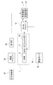
駆動部2は、モータの一例であるダイレクトドライブモータ(以下DDモータ)11を有しており、図7に示すように、DDモータ11は、モータドライバ12と、エンコーダ14に接続されている。また、モータドライバ12は、制御基板13に接続されている。DDモータ11は減速機等の中間機構を要さないため、駆動部2の小型化、騒音の低減の他、応答性能、速度安定性能、位置決め精度が向上する。よって、バタフライバルブ1による真空圧力制御の精度が高まる。また、DDモータ11は、図1および図2に示すように、回転軸11aを有しており、回転軸11aの回転中心軸を軸線RAとする。
図7に示すように、制御基板13には、モータドライバ12と、真空チャンバ32の圧力を検出する圧力計35が接続されている。制御基板13は、記憶手段131を有しており、記憶手段131には、例えば、バタフライ弁体9の全閉位置に対応するロッド10の回転角度およびバタフライ弁体9の全開位置に対応するロッド10の回転角度や、真空チャンバ32の任意の目標圧力等に対応するロッド10の回転角度が記憶されている。そして、記憶手段131から読み出される回転角度に基づき、モータドライバ12がDDモータ11の回転を制御する。
図1および図2に示すように、駆動部2は、ヒートシンク15と断熱部材16を介して、弁部3と連結している。弁部3は、流路30を流れる流体および後述するヒータ27により約200℃に熱せられるが、ヒートシンク15と断熱部材16により、弁部3の熱が、駆動部2に伝達されることを防いでいる。
弁部3は、バルブボディ8と、ロッド10と、バタフライ弁体9とを有している。バルブボディ8は、耐腐食性や耐熱性を有するステンレス鋼からなる。バルブボディ8は、図1中の右端部に入力ポート5を備えており、図1中の左端部に出力ポート6を備えている。入力ポート5の内壁には入力側流路8bが形成され、出力ポート6の内壁には出力側流路8cが形成されている。そして、入力側流路8bと出力側流路8cとの間には、断面円弧状の内壁からなる弁孔8aが形成されている。入力側流路8bと弁孔8aと出力側流路8cは、同軸上に設けられ、一連の流路30を構成する。入力ポート5は真空チャンバ32に、出力ポート6は真空ポンプ33に、それぞれ接続され、流路30によって真空チャンバの排気を行う。
また、バルブボディ8は、図2に示すように、温度センサとしての熱電対28を備えており、熱電対28は、バルブボディ8の温度を計測する。そして、バルブボディ8は、流路30を流れる流体の温度を保つため、弁孔8aを挟むように、一対のヒータ27を備えている。ヒータ27は、カートリッジヒータであり、バタフライバルブ1の外部の制御装置(図示せず)と接続されている。そして、ヒータ27は、制御装置によって熱電対28の計測値に基づいたONまたはOFFの制御がされ、バルブボディ8の温度を調整する。さらに、バルブボディ8は、サーモスタット29を備えている。サーモスタット29は、ヒータ27が暴走して、バルブボディ8が過剰に加熱された場合に作動する。サーモスタット29が作動すると、制御装置は、ヒータ27を停止させる。
さらに、バルブボディ8は、図1中の上面と弁孔8aとを貫通する挿通孔8dを有し、挿通孔8dにはロッド10が挿通されている。挿通孔8dに挿通されたロッド10は、弁孔8aに、流路30に対して直交する方向に架設されている。
ロッド10は、耐腐食性や耐熱性を有するステンレス鋼を削り出して、円柱状に形成されたものである。ロッド10の流路30に挿入されている部分は、弁体取付部10bを備えており、軸線RAに直交する方向の断面が略D字状となっている(図3,図4参照)。ロッド10の流路30に挿通されていない側の一端は、継手17を介してDDモータ11の回転軸11aに接続されている。継手17は、金属板ばね式のカップリングであり、継手17があることによって、ロッド10が流体により熱せられたとしても、その熱がDDモータ11に伝わりにくくなっている。
ロッド10と挿通孔8dの内壁と間には、シールのためOリング18,19,20がロッド10軸方向に3つ並んで配置されている。Oリング18,19,20は、ロッド10の外周面と挿通孔8dの内壁とに圧縮され、流路30を流れる流体が、挿通孔8dを通って駆動部2側へ漏れることを防止している。なお、Oリング18,19,20は、3つとも全て同一の種類のものである。
また、ロッド10は、流路30に挿通されている側の一端が、ブッシュ22によって回転可能に軸支されている。ブッシュ22は耐食性が高く、摺動性の良い樹脂からなる。また、ロッド10は、バルブボディ8の外側で、ロッド10の軸方向に隣接して並ぶ2つのボールベアリング21A,21Bによって、回転可能に軸支されている。ロッド10は、ボールベアリング21A,21Bと、ブッシュ22とによって両持ち状態に軸支されることで、回転中心軸が安定し、ぶれにくくなっている。
ボールベアリング21A,21Bのそれぞれは、カラー23と、軸受け押さえ24と、ロッド10のフランジ部10a(図6参照)とによって予圧されている。
予圧について、図6を用いて詳しく説明する。軸受け押さえ24の突起部24aが、ボールベアリング21Aとボールベアリング21Bの間に位置しており、ボールベアリング21Aの外輪211Aを矢印F1方向に押し広げるとともに、ボールベアリング21Bの外輪211BをF2方向に押し広げる。さらに、カラー23と、ロッド10のフランジ部10aによって、ボールベアリング21Aの内輪212Aが図中上方向(矢印F3)から圧縮され、ボールベアリング21Bの内輪212Bが図中下方向(矢印F4)から圧縮されている。
矢印F1,F2,F3,F4の方向から外輪211A,211Bと内輪212A,212Bに力をかけることで、外輪211A(211B)と転動体213A(213B)との接点CP1A(CP1B)と、内輪212A(212B)と転動体213A(213B)との接点CP2A(CP2B)とを結ぶ仮想線VLA(VLB)が、前記ロッドのラジアル方向(図中矢印RDの方向)に対して角度をもち、仮想線VLAと仮想線VLBが成す角度が、ロッド10に向かって広がるようになっている。
以上のように予圧されることによって、ボールベアリング21A,21Bは、内部すきまが発生しにくくなり、剛性が高まるため、ロッド10が回転する際の振動が抑えられ、ロッド10の回転中心軸のぶれが抑えられる。
バタフライ弁体9は、耐腐食性や耐熱性を有するステンレス鋼を削り出して円板状に形成されたものである。外径は、図2に示すように、弁孔8aの内径とほぼ同一であり、バタフライ弁体9の外周と、弁孔8aの内壁との隙間は極小となっている。また、バタフライ弁体9は、バタフライ弁体9の重心CG9(図5参照)の位置を調整するため、凹部9aを有しており、軸線RAに直交する方向の断面が略凹字状(略C字形状)となっている(図3,図4参照)。そして、バタフライ弁体9は、図5に示すように、ねじ25A,25B,25Cおよび座金26A,26B,26Cによりロッド10に結合され、ロッド10とともに回転結合体31をなしている。なお、ねじ25A,25B,25Cは3つとも全て同一種類のねじであり、座金26A,26B,26Cも3つとも全て同一種類の座金である。
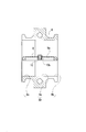
ロッド10と、バタフライ弁体9と、ねじ25A,25B,25Cおよび座金26A,26B,26Cと、からなる回転結合体31は、DDモータ11の回転軸11aが軸線RAを中心に正方向Kに回転すると、回転結合体31を構成するロッド10が回転軸11aと継手17を介して接続されているため、回転結合体31が正方向である矢印K(図1,2参照)の方向に回転する。これにより、弁孔8aを塞いでいたバタフライ弁体9が同方向に回転し、流路30が開放される全開位置となる(図4参照)。これにより、真空チャンバ32から大量の排気が可能となる。
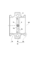
一方、DDモータ11の回転軸11aが軸線RAを中心に、開弁時とは逆方向の負方向である矢印-K(図1,2参照)の方向に回転すると、回転結合体31が-K方向に回転し、バタフライ弁体9が弁孔8aを塞ぐ全閉位置となる(図3参照)。このとき、バタフライ弁体9の外周面と弁孔8aの内壁との間には、極小の隙間が設けられているため、完全にシールされている状態ではなく、バタフライ弁体9は、絞りの役割を果たしている。したがって、真空チャンバ32は、排気が停止されることなく、絶えず排気されている状態にある。これは、ALDでは真空チャンバの圧力が制御できていれば良く、完全に流路30をシールする必要がないためである。また、回転結合体31は、エンコーダ14によって回転角度を把握されており、バタフライ弁体9が全開位置から全閉位置(または全閉位置から全開位置)に回転する際の回転角度は90°である。
また、回転結合体31の重心(結合体重心)は、DDモータ11の回転軸11aの回転中心軸である軸線RA上に位置している。これにより、DDモータ11によりロッド10が回転されても、ロッド10に対して遠心力が働きにくくなる。ロッド10に対して遠心力が働きにくくなれば、ロッド10の回転中心軸のぶれを抑えることが可能である。
回転結合体31の重心を軸線RA上に位置させるため、回転結合体31は、以下のように構成されている。
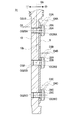
回転結合体31は、回転結合体31を構成するロッド10と、バタフライ弁体9と、ねじ25A,25B,25Cおよび座金26A,26B,26Cとのそれぞれの重心である構成部材重心のいずれもが、軸線RAを通る仮想平面VP(図3参照)上に置かれている。ここで、ロッド10の構成部材重心を重心CG10とし、バタフライ弁体9の構成部材重心を重心CG9とし、ねじ25A,25B,25Cの構成部材重心を、それぞれ重心CG25A,CG25B,CG25Cとし、座金26A,26B,26Cの構成部材重心を、それぞれ重心CG26A,CG26B,CG26Cとする(図5参照)。
そして、仮想平面VP上において、軸線RAによって区切られる一方の領域に置かれた構成部材重心と軸線RAとの距離を正の値とし、他方の領域に置かれた構成部材重心と軸線RAとの距離を負の値とし、構成部材ごとに、構成部材重心と軸線RAとの距離に各構成部材の質量を乗じたモーメントを算出し、当該算出したモーメントを合計した値が0となるように構成されている。
詳しく説明すると、図5に示すように、軸線RAによって区切られる紙面上右側の領域における、重心CG25Aと軸線RAとの距離D3Aと、重心CG25Bと軸線RAとの距離D3Bと、重心CG25Cと軸線RAとの距離D3Cと、重心CG26Aと軸線RAとの距離D4Aと、重心CG26Bと軸線RAとの距離D4Bと、重心CG26Cと軸線RAとの距離D4Cとを正の値とし、軸線RAによって区切られる左側の領域における、重心CG10と軸線RAとの距離D1を負の値とする(D3Aと、D3Bと、D3Cは全て同じ値であるため、以下D3に統一し、D4Aと、D4Bと、D4Cは全て同じ値であるため、以下D4に統一して説明する)。なお、バタフライ弁体9の重心CG9と軸線RAとの距離を距離D2とするが、本実施形態においては、重心CG9は軸線RA上にあるため、距離D2は0であり、図示していない。
そして、ロッド10の質量をW、バタフライ弁体9の質量をX、ねじ25A,25B,25Cの質量をそれぞれY、座金26A,26B,26Cの質量をそれぞれZとすれば、ロッド10に働くモーメントはW×D1であり、バタフライ弁体9に働くモーメントはX×D2であり、ねじ25A,25B,25Cに働くモーメントはそれぞれY×D3であり、座金26A,26B,26Cに働くモーメントはそれぞれZ×D4と算出される。
そして、それぞれのモーメントを合計した値(すなわち、W×D1+X×D2+(Y×D3)×3+(Z×D4)×3)が、0となるように構成されている。回転結合体31を以上のような構成とすることで、回転結合体31を構成する各構成部材に働くモーメントのバランスが、軸線RA上で取られることとなり、回転結合体31の重心が、軸線RA上に位置することとなる。なお、図5に図示される重心の位置は全て一例であり、図示される内容に限定されるものではない。
次に、バタフライバルブ1を用いた真空圧力制御の概要を説明する。バタフライ弁体9は、図3に示す全閉位置にある場合でも、弁孔8aの内周面に対して極小の隙間を持っているため、絞りの役割を果たすものである。したがって、バタフライバルブ1は、真空ポンプ33の吸引により、常に真空チャンバ32の排気を行っている。図4に示すのが、バタフライ弁体9の全開位置であり、バタフライ弁体9は、真空チャンバ32が目標の圧力となるように、全閉位置(回転角度0°)から、全開位置(回転角度90°)までの間で、任意の回転角度をもって回転し、流路30の流路面積を調整する。
例えば、全閉位置の状態、または、任意の回転角度で回転された位置から、より大量に排気を行い、真空チャンバ32の圧力を低下させる場合、バタフライバルブ1の制御基板13は、記憶手段131から目標とする圧力に対応する回転角度を読み出す。そして、読み出された回転角度に基づき、モータドライバ12が、エンコーダ14を用いてDDモータ11を駆動する。ロッド10は、DDモータ11により、読み出された回転角度まで正方向Kに回転する。ロッド10とともに回転結合体31を構成するバタフライ弁体9は、ロッド10と一体的に正方向Kに回転し、絞られていた流路30の流路面積を拡大させていく。
全開位置の状態、または任意の回転角度で回転された位置から、排気する量を絞り、真空チャンバ32の圧力を上昇させる場合は、バタフライバルブ1の制御基板13は、記憶手段131から目標とする圧力に対応する回転角度を読み出す。そして、読み出された回転角度に基づき、モータドライバ12が、エンコーダ14を用いてDDモータ11を駆動する。そして、ロッド10は、真空チャンバ32の圧力を低下させる場合とは逆方向である-K方向に回転する。ロッド10とともに回転結合体31を構成するバタフライ弁体9は、ロッド10と一体的に-K方向に回転し、拡大されていた流路30の流路面積を絞っていく。
なお、回転結合体31の変形例として、バタフライ弁体9をロッド10に結合するために、ねじ25A,25B,25Cおよび座金26A,26B,26Cを用いる他、図8に示すように、リベット36A,36B,36Cを用いることが考えられる。
リベット36A,36B,36Cを用いることで構成される回転結合体41について説明する。図8に示すように、バタフライ弁体9は、ロッド10に対してリベット36A,36B,36Cによって固定されている。
回転結合体41の重心を軸線RA上に位置させるため、ロッド10、バタフライ弁体9、リベット36A,36B,36Cのそれぞれに働くモーメントの合計が0となるように構成されている。つまり、リベット36A,36B,36Cのそれぞれの構成部材重心を、それぞれ重心CG36A,CG36B,CG36Cとし、それぞれの重心CG36A,CG36B,CG36Cと、軸線RAとの距離を、D5A,D5B,D5Cとし(D5Aと、D5Bと、D5Cは全て同じ値であるため、以下D5に統一して説明する)、さらに、リベット36A,36B,36C、それぞれの質量をVとすれば、W×D1+X×D2+(V×D5)×3=0となるように構成されているのである。回転結合体41を以上のような構成とすることで、回転結合体41の重心は、軸線RA上に位置することとなる。
さらに、回転結合体31の変形例として、バタフライ弁体9とロッド10との結合を、溶接により行うことが考えられる。溶接により結合を行った場合、溶接により生じるビードの量を制御することが困難であるため、重心の位置の制御が困難となる。したがって、溶接を行った後にビードを削り取る必要がある。ビードを削り取ることで、ロッド10の質量Wと距離D1を乗じて求まるモーメントおよびバタフライ弁体9の質量Xと距離D2とを乗じて求まるモーメントのみを考慮して回転結合体を構成すれば、回転結合体の重心を軸線RA上に位置させることができる。
以上説明したように、本実施形態のバタフライバルブ1によれば、 モータ(DDモータ11)と、流路30と、モータ(DDモータ11)に接続され、流路30に対して直交する方向に配置されたロッド10と、ロッド10に結合され、モータ(DDモータ11)によりロッド10が回転することで流路30の開閉を行うバタフライ弁体9と、を有するバタフライバルブ1において、少なくともロッド10とバタフライ弁体9とを構成部材とする結合体(回転結合体31)の重心である結合体重心が、モータ(DDモータ11)の回転軸11aの軸線RA上に位置している。よって、モータ(DDモータ11)によりロッド10が回転されても、ロッド10に対して遠心力が働きにくくなる。ロッド10に対して遠心力が働きにくくなれば、ロッド10の回転中心軸のぶれを抑えることが可能である。そして、回転中心軸のぶれを抑えることができれば、ロッド10を軸支するボールベアリング21A,21Bに対する負荷を軽減できるほか、バタフライ弁体9が流路30(弁孔8a)の内壁に干渉することも防止することができるため、バタフライバルブ1の寿命も改善される。
また、本実施形態のバタフライバルブ1によれば、結合体(回転結合体31)は、結合体(回転結合体31)を構成するそれぞれの構成部材(バタフライ弁体9と、ロッド10と、ねじ25A,25B,25Cと、座金26A,26B,26C)の重心である構成部材重心(重心CG9,CG10,CG25A,CG25B,CG25C,CG26A,CG26B,CG26C)のいずれもが、回転軸11aの軸線RAを通る仮想平面VP上に置かれ、仮想平面VP上において、回転軸11aの軸線RAによって区切られる一方の領域に置かれた構成部材重心(重心CG25A,CG25B,CG25C,CG26A,CG26B,CG26C)と、軸線RAと、の距離を正の値とし、他方の領域に置かれた構成部材重心(重心CG10)と、軸線RAと、の距離を負の値とし、構成部材(バタフライ弁体9と、ロッド10と、ねじ25A,25B,25Cと、座金26A,26B,26C)ごとに、構成部材重心(重心CG9,CG10,CG25A,CG25B,CG25C,CG26A,CG26B,CG26C)と軸線RAとの距離に、各構成部材の質量(W,X,Y,Z)を乗じたモーメントを算出し、当該算出したモーメントを合計した値が略0となるように構成されている。よって、結合体(回転結合体31)を構成する各構成部材に働くモーメントのバランスが、軸線RA上で取られることとなり、結合体(回転結合体31)の結合体重心が、軸線RA上に位置することとなる。よって、モータ(DDモータ11)によりロッド10が回転されても、ロッド10に対して遠心力が働きにくくなり、ロッド10の回転中心軸のぶれを抑えることが可能である。
また、本実施形態のバタフライバルブ1によれば、結合体(回転結合体31)は、ロッド10にバタフライ弁体9が固定具により結合されることで成り、結合体重心は、固定具の重心も考慮したものであること、また、固定具は、ねじ25A,25B,25Cおよび座金26A,26B,26Cまたはリベット36A,36B,36Cのいずれかである。よって、結合体(回転結合体31)は、ロッド10にバタフライ弁体9が、ねじ25A,25B,25Cおよび座金26A,26B,26Cまたはリベット36A,36B,36Cといった固定具により結合されることで成り、結合体重心は、固定具の重心も考慮したものである。そのため、固定具を含めた結合体(回転結合体31)の結合体重心が、モータ(DDモータ11)の回転軸の軸線上に位置しており、モータ(DDモータ11)によりロッド10が回転されても、ロッド10に対して遠心力が働きにくくなる。ロッド10に対して遠心力が働きにくくなれば、ロッド10の回転中心軸のぶれを抑えることが可能である。
また、本実施形態のバタフライバルブ1によれば、結合体(回転結合体31)は、ロッド10にバタフライ弁体9を溶接により結合することで成り、溶接によって生じるビードは取り除かれている。よって、結合体重心は、溶接によって生じるビードの重心に左右されることなく、ロッド10の重心CG10およびバタフライ弁体9の重心CG9のみによって定まる。
また、本実施形態のバタフライバルブ1によれば、モータは、DDモータ11である。よって、ロッド10を回転させるモータが、DDモータ11であるため、ロッド10を高速回転させることができる。従来は、バタフライバルブ1には、ステッピングモータが用いられることが多かったが、ステッピングモータを用いた場合、バタフライ弁体9の全開から全閉まで(または全閉から全開まで)の時間が、例えば0.5秒程度と、ALDで求められる、例えば0.1秒という速度を満足することが困難であった。そこで、DDモータ11を用いることで高速化することが考えられたが、高速化することにより、遠心力による回転中心軸のぶれが生じやすく、ロッド10を軸支するボールベアリング21A,21Bに対する負荷が過大となって損傷を受けたり、バタフライ弁体9が流路30(弁孔8a)の内壁に干渉してしまうなど、バタフライバルブ1の寿命に悪影響を与えるという問題点が顕在化していた。しかし、本発明は、ロッド10とバタフライ弁体9の結合体(回転結合体31)の重心である結合体重心が、DDモータ11の回転軸11aの軸線RA上に位置しているため、ロッド10に対して遠心力が働きにくく、ロッド10の回転中心軸のぶれを抑えることが可能である。よって、上記問題点が解消され、DDモータ11によるバタフライ弁体9の開閉の高速化を実現することができる。
また、本実施形態のバタフライバルブ1によれば、ロッド10は、ロッド10の軸方向に隣接して並ぶ2つのボールベアリング21A,21Bと、ブッシュ22と、によって両持ち状態に軸支されている。2つのボールベアリング21A,21Bは、それぞれ、外輪211A,211Bと、内輪212A,212Bと、外輪211A,211Bと内輪212A,212Bとの間に配置される転動体213A,213Bと、からなる。2つのボールベアリング21A,21Bのそれぞれは予圧され、外輪211A,211Bと転動体213A,213Bとの接点と、内輪212A,212Bと転動体213A,213Bとの接点とを結ぶ仮想線VLA,VLBが、ロッドのラジアル方向に対して角度をもち、2つのボールベアリングのそれぞれの仮想線VLA,VLBが成す角度が、ロッド10に向かって広がるように配置されている。よって、ロッド10は、ロッド10の軸方向に隣接して並ぶ2つのボールベアリング21A,21Bと、ブッシュ22と、によって両持ち状態に軸支されているため、より回転中心軸が安定し、ぶれにくくなる。
また、2つのボールベアリング21A,21Bのそれぞれは、外輪211A,211Bと転動体213A,213bとの接点と、内輪212A,212Bと転動体213A,213Bとの接点とを結ぶ仮想線VLA,VLBが、ロッド10のラジアル方向に対して角度をもつように構成され、2つのボールベアリング21A,21Bのそれぞれの仮想線VLA,VLBが成す角度が、ロッド10に向かって広がるように配置されているため、ロッド10を軸支するボールベアリング21A,21Bの内部すきまが発生しにくくなり、剛性が高まる。ボールベアリング21A,21Bの剛性が高まると、ロッド10が回転する際の振動が抑えられ、ロッド10の回転中心軸のぶれが抑えられる。
また、本実施形態のバタフライバルブ1によれば、流路30を内部に有するバルブボディ8の温度を計測する温度センサ(熱電対28)と、温度センサ(熱電対28)の計測値に基づき、バルブボディ8の温度を調整するヒータ27と、バルブボディ8の過昇温を検知するサーモスタット29と、を備える。よって、熱電対28とヒータ27により、バルブボディ8の温度を調整することができる。また、サーモスタット29により、バルブボディ8の過昇温を検知できるため、ヒータ27の暴走により過剰にバルブボディ8が熱せられることがない。
なお、本実施形態は単なる例示にすぎず、本発明を何ら限定するものではない。したがって本発明は当然に、その要旨を逸脱しない範囲内で様々な改良、変形が可能である。例えば、本実施形態においては、バタフライ弁体9が全閉位置にあっても、流路30を完全にシールするものとなっていないが、弁孔8aに弁座を設け、弁座にバタフライ弁体9を当接させることで、完全にシールできるものとしても良い。
1 バタフライバルブ
9 バタフライ弁体
10 ロッド
11 DDモータ(モータの一例)
11a 回転軸
30 流路
31 回転結合体(結合体の一例)
RA 軸線
9 バタフライ弁体
10 ロッド
11 DDモータ(モータの一例)
11a 回転軸
30 流路
31 回転結合体(結合体の一例)
RA 軸線
Claims (8)
- モータと、流路と、前記モータに接続され、前記流路に対して直交する方向に配置されたロッドと、前記ロッドに結合され、前記モータにより前記ロッドが回転することで前記流路の開閉を行うバタフライ弁体と、を有するバタフライバルブにおいて、
少なくとも前記ロッドと前記バタフライ弁体とを構成部材とする結合体の重心である結合体重心が、前記モータの回転軸の軸線の上に位置していること、
を特徴とするバタフライバルブ。 - 請求項1に記載のバタフライバルブにおいて、
前記結合体は、
前記結合体を構成するそれぞれの構成部材の重心である構成部材重心のいずれもが、前記軸線を通る仮想平面上に置かれ、
前記仮想平面上において、前記軸線によって区切られる一方の領域に置かれた前記構成部材重心と、前記軸線との距離を正の値とし、他方の領域に置かれた前記構成部材重心と、前記軸線との距離を負の値とし、
前記構成部材ごとに、前記構成部材重心と前記軸線との距離に、前記各構成部材の質量を乗じたモーメントを算出し、当該算出したモーメントを合計した値が略0となるように構成されていること、
を特徴とするバタフライバルブ。 - 請求項1または2に記載のバタフライバルブにおいて、
前記結合体は、前記ロッドに前記バタフライ弁体が固定具により結合されることで成り、前記結合体重心は、前記固定具の重心も考慮したものであること、
を特徴とするバタフライバルブ。 - 請求項3に記載のバタフライバルブにおいて、
前記固定具は、ねじおよび座金またはリベットのいずれかであること、
を特徴とするバタフライバルブ。 - 請求項1または2に記載のバタフライバルブにおいて、
前記結合体は、前記ロッドに前記バタフライ弁体を溶接により結合することで成り、前記溶接によって生じるビードは取り除かれていること、
を特徴とするバタフライバルブ。 - 請求項1乃至5のいずれか1つに記載のバタフライバルブにおいて、
前記モータは、ダイレクトドライブモータであること、
を特徴とするバタフライバルブ。 - 請求項1乃至6のいずれか1つに記載のバタフライバルブにおいて、
前記ロッドは、前記ロッドの軸方向に隣接して並ぶ2つのボールベアリングと、ブッシュと、によって両持ち状態に軸支されていること、
前記2つのボールベアリングのそれぞれは、外輪と、内輪と、前記外輪と前記内輪との間に配置される転動体と、からなり、
前記2つボールベアリングのそれぞれは予圧され、前記外輪と前記転動体との接点と、前記内輪と前記転動体との接点とを結ぶ仮想線が、前記ロッドのラジアル方向に対して角度をもち、
前記2つのボールベアリングのそれぞれの前記仮想線が成す角度が、前記ロッドに向かって広がるように配置されていること、
を特徴とするバタフライバルブ。 - 請求項1乃至7のいずれか1つに記載のバタフライバルブにおいて、
前記流路を内部に有するバルブボディの温度を計測する温度センサと、前記温度センサの計測値に基づき、前記バルブボディの温度を調整するヒータと、前記バルブボディの過昇温を検知するサーモスタットと、を備えること、
を特徴とするバタフライバルブ。
Priority Applications (3)
| Application Number | Priority Date | Filing Date | Title |
|---|---|---|---|
| US17/430,175 US11466782B2 (en) | 2019-03-26 | 2020-02-21 | Butterfly valve |
| CN202080022838.4A CN113614427B (zh) | 2019-03-26 | 2020-02-21 | 蝶形阀 |
| KR1020217029571A KR102548673B1 (ko) | 2019-03-26 | 2020-02-21 | 버터플라이 밸브 |
Applications Claiming Priority (2)
| Application Number | Priority Date | Filing Date | Title |
|---|---|---|---|
| JP2019058336A JP6959953B2 (ja) | 2019-03-26 | 2019-03-26 | バタフライバルブ |
| JP2019-058336 | 2019-03-26 |
Publications (1)
| Publication Number | Publication Date |
|---|---|
| WO2020195418A1 true WO2020195418A1 (ja) | 2020-10-01 |
Family
ID=72610488
Family Applications (1)
| Application Number | Title | Priority Date | Filing Date |
|---|---|---|---|
| PCT/JP2020/006985 Ceased WO2020195418A1 (ja) | 2019-03-26 | 2020-02-21 | バタフライバルブ |
Country Status (6)
| Country | Link |
|---|---|
| US (1) | US11466782B2 (ja) |
| JP (1) | JP6959953B2 (ja) |
| KR (1) | KR102548673B1 (ja) |
| CN (1) | CN113614427B (ja) |
| TW (1) | TWI748351B (ja) |
| WO (1) | WO2020195418A1 (ja) |
Families Citing this family (1)
| Publication number | Priority date | Publication date | Assignee | Title |
|---|---|---|---|---|
| KR102551928B1 (ko) * | 2022-12-08 | 2023-07-05 | 주식회사 파인솔루션 | 히팅 타입 스로틀 밸브 장치 |
Citations (10)
| Publication number | Priority date | Publication date | Assignee | Title |
|---|---|---|---|---|
| JPH0545343U (ja) * | 1991-11-15 | 1993-06-18 | エヌオーケー株式会社 | バタフライバルブ |
| JPH0828715A (ja) * | 1994-07-20 | 1996-02-02 | Tomoe Gijutsu Kenkyusho:Kk | バタフライ弁のダイナミックトルク測定方式及びそのためのバタフライ弁本体 |
| JPH08170735A (ja) * | 1994-12-16 | 1996-07-02 | Nippondenso Co Ltd | バタフライバルブ |
| JP2001214987A (ja) * | 2000-02-02 | 2001-08-10 | Benkan Corp | 真空排気弁 |
| US20100270489A1 (en) * | 2009-04-24 | 2010-10-28 | Honeywell International Inc. | Butterfly valve assembly including a bearing assembly for serrated spline constraint |
| JP2011058536A (ja) * | 2009-09-08 | 2011-03-24 | Denso Corp | 流体制御弁およびその製造方法 |
| US20130167815A1 (en) * | 2011-11-23 | 2013-07-04 | Bernd Bareis | Low pressure valve, for controlling exhaust gas recirculation |
| US20150219148A1 (en) * | 2014-01-31 | 2015-08-06 | New Hampshire Ball Bearings, Inc. | Bearing system and methods of use thereof |
| JP2015169280A (ja) * | 2014-03-07 | 2015-09-28 | 大豊工業株式会社 | バルブアセンブリ |
| JP2017141954A (ja) * | 2016-02-11 | 2017-08-17 | Ckd株式会社 | 真空圧力制御装置 |
Family Cites Families (16)
| Publication number | Priority date | Publication date | Assignee | Title |
|---|---|---|---|---|
| AT329813B (de) * | 1973-07-03 | 1976-05-25 | Siegwart Emil | Stromungsregler fur luftleitungen |
| JPS643119U (ja) * | 1987-06-24 | 1989-01-10 | ||
| JPH01255716A (ja) * | 1988-04-01 | 1989-10-12 | Sharp Corp | 超電導体軸受け |
| JPH02165476A (ja) * | 1988-12-19 | 1990-06-26 | Fuji Electric Co Ltd | 磁気ディスク装置 |
| CN2247258Y (zh) * | 1995-12-23 | 1997-02-12 | 刘平 | 用于部分回转阀门的电动装置 |
| DE19918128A1 (de) * | 1999-04-21 | 2000-10-26 | Dieter Moellmann | Absperrklappe für Rohrleitungen und Verfahren zur Herstellung derselben |
| JP3098236B1 (ja) * | 1999-08-23 | 2000-10-16 | リックス株式会社 | ロータリジョイントの軸受け構造 |
| JP4354309B2 (ja) * | 2004-03-12 | 2009-10-28 | 株式会社キッツ | バタフライ弁 |
| US7032885B2 (en) * | 2004-07-22 | 2006-04-25 | Automotive Components Holdings, Llc | Throttle body and method of assembly |
| US20080006328A1 (en) * | 2006-07-06 | 2008-01-10 | Honeywell International, Inc. | Electric motor pressure relief plate |
| JP4990808B2 (ja) * | 2008-01-28 | 2012-08-01 | セイコーインスツル株式会社 | アーム支持機構および情報再生装置 |
| KR101476518B1 (ko) * | 2010-04-13 | 2014-12-24 | 가부시키가이샤 도모에 기쥬츠 겐큐쇼 | 버터플라이 밸브의 밸브체 |
| CN201891510U (zh) | 2010-09-10 | 2011-07-06 | 胜利油田胜利动力机械集团有限公司 | 自动电动蝶阀 |
| CN107061758B (zh) | 2016-02-11 | 2019-04-12 | Ckd株式会社 | 真空压力控制装置 |
| US9915352B2 (en) * | 2016-08-03 | 2018-03-13 | Scc, Inc. | Butterfly valve utilizing spring for consistent disk placement |
| JP7013152B2 (ja) | 2017-07-13 | 2022-01-31 | Ckd株式会社 | バタフライバルブおよび真空圧力制御装置 |
-
2019
- 2019-03-26 JP JP2019058336A patent/JP6959953B2/ja active Active
-
2020
- 2020-02-21 US US17/430,175 patent/US11466782B2/en active Active
- 2020-02-21 CN CN202080022838.4A patent/CN113614427B/zh active Active
- 2020-02-21 KR KR1020217029571A patent/KR102548673B1/ko active Active
- 2020-02-21 WO PCT/JP2020/006985 patent/WO2020195418A1/ja not_active Ceased
- 2020-02-24 TW TW109105834A patent/TWI748351B/zh active
Patent Citations (10)
| Publication number | Priority date | Publication date | Assignee | Title |
|---|---|---|---|---|
| JPH0545343U (ja) * | 1991-11-15 | 1993-06-18 | エヌオーケー株式会社 | バタフライバルブ |
| JPH0828715A (ja) * | 1994-07-20 | 1996-02-02 | Tomoe Gijutsu Kenkyusho:Kk | バタフライ弁のダイナミックトルク測定方式及びそのためのバタフライ弁本体 |
| JPH08170735A (ja) * | 1994-12-16 | 1996-07-02 | Nippondenso Co Ltd | バタフライバルブ |
| JP2001214987A (ja) * | 2000-02-02 | 2001-08-10 | Benkan Corp | 真空排気弁 |
| US20100270489A1 (en) * | 2009-04-24 | 2010-10-28 | Honeywell International Inc. | Butterfly valve assembly including a bearing assembly for serrated spline constraint |
| JP2011058536A (ja) * | 2009-09-08 | 2011-03-24 | Denso Corp | 流体制御弁およびその製造方法 |
| US20130167815A1 (en) * | 2011-11-23 | 2013-07-04 | Bernd Bareis | Low pressure valve, for controlling exhaust gas recirculation |
| US20150219148A1 (en) * | 2014-01-31 | 2015-08-06 | New Hampshire Ball Bearings, Inc. | Bearing system and methods of use thereof |
| JP2015169280A (ja) * | 2014-03-07 | 2015-09-28 | 大豊工業株式会社 | バルブアセンブリ |
| JP2017141954A (ja) * | 2016-02-11 | 2017-08-17 | Ckd株式会社 | 真空圧力制御装置 |
Also Published As
| Publication number | Publication date |
|---|---|
| CN113614427A (zh) | 2021-11-05 |
| TW202040033A (zh) | 2020-11-01 |
| TWI748351B (zh) | 2021-12-01 |
| KR20210119542A (ko) | 2021-10-05 |
| CN113614427B (zh) | 2023-09-05 |
| US11466782B2 (en) | 2022-10-11 |
| JP6959953B2 (ja) | 2021-11-05 |
| JP2020159431A (ja) | 2020-10-01 |
| US20220099192A1 (en) | 2022-03-31 |
| KR102548673B1 (ko) | 2023-06-28 |
Similar Documents
| Publication | Publication Date | Title |
|---|---|---|
| US20190153896A1 (en) | Squeeze film damper for a gas turbine engine | |
| EP3171047A1 (en) | Gas lubricated foil bearing with self-induced cooling | |
| JP7013152B2 (ja) | バタフライバルブおよび真空圧力制御装置 | |
| CN108474295B (zh) | 涡轮增压器、发动机系统、涡轮增压器的控制方法 | |
| KR102525904B1 (ko) | 비밀폐식 버터플라이밸브 및 그의 제조방법 | |
| JP5846351B2 (ja) | ウェイストゲート弁の駆動機構及びターボチャージャ | |
| JP2001050451A (ja) | 交替する媒体のためのロータリジョイント | |
| JP2002089257A (ja) | 制御マフラ用バルブおよび制御マフラ用バルブの弁体組み付け方法 | |
| JP6959953B2 (ja) | バタフライバルブ | |
| CN110925197B (zh) | 涡旋机及其轴向背压动态控制方法、存储介质 | |
| JP2021116846A (ja) | バタフライバルブ | |
| JP4355915B2 (ja) | ガスタービンエンジンの流体流を調整する方法及び装置 | |
| JPWO2017150450A1 (ja) | ノズル駆動機構、過給機、および、可変容量型過給機 | |
| WO2017006865A1 (ja) | 軸受構造、および、過給機 | |
| JP2009209935A (ja) | ガスタービンエンジンの流体流調整方法および装置 | |
| JP6721351B2 (ja) | バルブ装置及び排熱回収システム | |
| JP6189224B2 (ja) | ジャーナル軸受及び蒸気タービン | |
| JP2019506562A (ja) | 排気タービン式過給機のための制御装置 | |
| RU2562503C2 (ru) | Центрирующее устройство, входной направляющий лопаточный аппарат и турбомашина | |
| JP6485241B2 (ja) | バルブ取付部材の固定方法及びバルブ取付部材の固定装置 | |
| JP2007040119A (ja) | 流体機械 | |
| JP6424968B2 (ja) | 流量可変バルブ機構及び過給機 | |
| WO2026079161A1 (ja) | 空気静圧軸受 | |
| JP2014211210A (ja) | バルブ装置 | |
| WO2015097525A1 (en) | Supercharger |
Legal Events
| Date | Code | Title | Description |
|---|---|---|---|
| 121 | Ep: the epo has been informed by wipo that ep was designated in this application |
Ref document number: 20778430 Country of ref document: EP Kind code of ref document: A1 |
|
| ENP | Entry into the national phase |
Ref document number: 20217029571 Country of ref document: KR Kind code of ref document: A |
|
| NENP | Non-entry into the national phase |
Ref country code: DE |
|
| 122 | Ep: pct application non-entry in european phase |
Ref document number: 20778430 Country of ref document: EP Kind code of ref document: A1 |