WO2020195231A1 - 車両における路面状態判定装置、運転支援システムおよび路面状態判定方法 - Google Patents
車両における路面状態判定装置、運転支援システムおよび路面状態判定方法 Download PDFInfo
- Publication number
- WO2020195231A1 WO2020195231A1 PCT/JP2020/004840 JP2020004840W WO2020195231A1 WO 2020195231 A1 WO2020195231 A1 WO 2020195231A1 JP 2020004840 W JP2020004840 W JP 2020004840W WO 2020195231 A1 WO2020195231 A1 WO 2020195231A1
- Authority
- WO
- WIPO (PCT)
- Prior art keywords
- road surface
- surface condition
- road
- vehicle
- condition determination
- Prior art date
- Legal status (The legal status is an assumption and is not a legal conclusion. Google has not performed a legal analysis and makes no representation as to the accuracy of the status listed.)
- Ceased
Links
Images


Classifications
-
- B—PERFORMING OPERATIONS; TRANSPORTING
- B60—VEHICLES IN GENERAL
- B60W—CONJOINT CONTROL OF VEHICLE SUB-UNITS OF DIFFERENT TYPE OR DIFFERENT FUNCTION; CONTROL SYSTEMS SPECIALLY ADAPTED FOR HYBRID VEHICLES; ROAD VEHICLE DRIVE CONTROL SYSTEMS FOR PURPOSES NOT RELATED TO THE CONTROL OF A PARTICULAR SUB-UNIT
- B60W40/00—Estimation or calculation of non-directly measurable driving parameters for road vehicle drive control systems not related to the control of a particular sub unit, e.g. by using mathematical models
- B60W40/02—Estimation or calculation of non-directly measurable driving parameters for road vehicle drive control systems not related to the control of a particular sub unit, e.g. by using mathematical models related to ambient conditions
- B60W40/06—Road conditions
-
- G—PHYSICS
- G06—COMPUTING OR CALCULATING; COUNTING
- G06T—IMAGE DATA PROCESSING OR GENERATION, IN GENERAL
- G06T7/00—Image analysis
- G06T7/0002—Inspection of images, e.g. flaw detection
- G06T7/0004—Industrial image inspection
-
- G—PHYSICS
- G06—COMPUTING OR CALCULATING; COUNTING
- G06T—IMAGE DATA PROCESSING OR GENERATION, IN GENERAL
- G06T7/00—Image analysis
-
- G—PHYSICS
- G08—SIGNALLING
- G08G—TRAFFIC CONTROL SYSTEMS
- G08G1/00—Traffic control systems for road vehicles
- G08G1/16—Anti-collision systems
-
- B—PERFORMING OPERATIONS; TRANSPORTING
- B60—VEHICLES IN GENERAL
- B60W—CONJOINT CONTROL OF VEHICLE SUB-UNITS OF DIFFERENT TYPE OR DIFFERENT FUNCTION; CONTROL SYSTEMS SPECIALLY ADAPTED FOR HYBRID VEHICLES; ROAD VEHICLE DRIVE CONTROL SYSTEMS FOR PURPOSES NOT RELATED TO THE CONTROL OF A PARTICULAR SUB-UNIT
- B60W2420/00—Indexing codes relating to the type of sensors based on the principle of their operation
- B60W2420/40—Photo, light or radio wave sensitive means, e.g. infrared sensors
- B60W2420/403—Image sensing, e.g. optical camera
-
- B—PERFORMING OPERATIONS; TRANSPORTING
- B60—VEHICLES IN GENERAL
- B60W—CONJOINT CONTROL OF VEHICLE SUB-UNITS OF DIFFERENT TYPE OR DIFFERENT FUNCTION; CONTROL SYSTEMS SPECIALLY ADAPTED FOR HYBRID VEHICLES; ROAD VEHICLE DRIVE CONTROL SYSTEMS FOR PURPOSES NOT RELATED TO THE CONTROL OF A PARTICULAR SUB-UNIT
- B60W2420/00—Indexing codes relating to the type of sensors based on the principle of their operation
- B60W2420/40—Photo, light or radio wave sensitive means, e.g. infrared sensors
- B60W2420/408—Radar; Laser, e.g. lidar
-
- B—PERFORMING OPERATIONS; TRANSPORTING
- B60—VEHICLES IN GENERAL
- B60W—CONJOINT CONTROL OF VEHICLE SUB-UNITS OF DIFFERENT TYPE OR DIFFERENT FUNCTION; CONTROL SYSTEMS SPECIALLY ADAPTED FOR HYBRID VEHICLES; ROAD VEHICLE DRIVE CONTROL SYSTEMS FOR PURPOSES NOT RELATED TO THE CONTROL OF A PARTICULAR SUB-UNIT
- B60W2552/00—Input parameters relating to infrastructure
- B60W2552/35—Road bumpiness, e.g. potholes
-
- G—PHYSICS
- G06—COMPUTING OR CALCULATING; COUNTING
- G06T—IMAGE DATA PROCESSING OR GENERATION, IN GENERAL
- G06T2207/00—Indexing scheme for image analysis or image enhancement
- G06T2207/10—Image acquisition modality
- G06T2207/10004—Still image; Photographic image
- G06T2207/10012—Stereo images
-
- G—PHYSICS
- G06—COMPUTING OR CALCULATING; COUNTING
- G06T—IMAGE DATA PROCESSING OR GENERATION, IN GENERAL
- G06T2207/00—Indexing scheme for image analysis or image enhancement
- G06T2207/10—Image acquisition modality
- G06T2207/10028—Range image; Depth image; 3D point clouds
-
- G—PHYSICS
- G06—COMPUTING OR CALCULATING; COUNTING
- G06T—IMAGE DATA PROCESSING OR GENERATION, IN GENERAL
- G06T2207/00—Indexing scheme for image analysis or image enhancement
- G06T2207/30—Subject of image; Context of image processing
- G06T2207/30248—Vehicle exterior or interior
- G06T2207/30252—Vehicle exterior; Vicinity of vehicle
- G06T2207/30256—Lane; Road marking
Definitions
- This disclosure relates to a technology for determining a road surface condition in a vehicle.
- a technique for detecting the environment around the vehicle by using a target detector such as an image pickup device and a radar has been proposed (for example, Japanese Patent Application Laid-Open No. 2017-182139).
- the first aspect provides a road surface condition determination device in a vehicle.
- the road surface condition determining device acquires information of a change pixel whose brightness value changes according to an absolute displacement of the road surface condition or a relative displacement of the road surface condition with respect to a traveling vehicle as a first detection signal. It includes an acquisition unit and a control unit that determines a road surface condition using the first detection signal.
- the road surface condition of the road can be accurately determined.
- the second aspect provides a road surface condition determination method.
- the information of the change pixel whose brightness value changes according to the absolute displacement of the road surface condition or the relative displacement of the road surface condition with respect to the traveling vehicle is acquired as the first detection signal.
- the first detection signal is used to determine the type of road surface condition.
- the road surface condition of the road can be accurately determined.
- the present disclosure can also be realized as a road surface condition determination program or a computer-readable recording medium for recording the program.
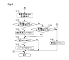
- Explanatory drawing showing an example of a vehicle equipped with the road surface condition determination device and a driving support system according to the first embodiment, A block diagram showing a functional configuration of the road surface condition determination device according to the first embodiment, A flowchart showing a processing flow of a road surface condition determination process executed by the road surface condition determination device according to the first embodiment. A flowchart showing a processing flow of a road surface condition determination process executed by the road surface condition determination device according to the first embodiment. A flowchart showing a processing flow of driving support processing executed by the driving support system according to the first embodiment.
- Explanatory drawing showing an example of road boundary and water flow in the horizontal direction when the road is viewed from above.
- Explanatory drawing showing an example of the road boundary and the water surface in the vertical direction when the road is viewed from the vehicle.
- Explanatory drawing which shows typically the appearance of unevenness on the road surface with the progress of a vehicle.
- the road surface condition determination device, the driving support system, and the road surface condition determination method in the vehicle according to the present disclosure will be described below based on some embodiments.
- the road surface condition determination device 100 in the vehicle according to the first embodiment is mounted on the vehicle 500 and used.
- the road surface condition determination device 100 may include at least a control unit and an acquisition unit, and the driving support system 10 includes a radar ECU 21, a millimeter wave radar 211, a camera ECU 22, and a camera as detectors in addition to the road surface condition determination device 100. It includes 221 and an event camera ECU 26, an event camera 261 and a driving support execution device 31.
- the detector at least the camera ECU 22 and the camera 221 may be provided in addition to the event camera ECU 26 and the event camera 261.
- the vehicle 500 further includes a rotation angle sensor 23, a wheel speed sensor 24, and a yaw rate sensor 25.
- the vehicle 500 further includes wheels 501, a braking device 502, a braking line 503, a steering wheel 504, a windshield 510, a front bumper 520 and a rear bumper 521.
- the vehicle 500 includes at least one of an internal combustion engine and an electric motor as a driving force source 505 for traveling the vehicle.
- the radar ECU 21 is connected to a millimeter-wave radar 211 that emits radio waves to detect reflected waves from a target, and uses the reflected waves acquired by the millimeter-wave radar 211 to detect an object, that is, an object by a reflection point.
- a second detection signal representing the target is generated and output.
- the camera ECU 22 is connected to the monocular camera 221 and identifies the target shape from the captured image acquired by the camera 221 and determines the target by pattern matching processing using the shape pattern of the target prepared in advance.
- a second detection signal indicating the type of object is generated and output. Identification of the target shape is performed, for example, by semantic segmentation using machine learning.
- pixel value information R, G, B
- coordinate information as position information are associated with the pixels included in each frame of the captured image.
- the radar ECU 21 and the millimeter wave radar 211, and the camera ECU 22 and the camera 221 correspond to a second detector that acquires information on an object around the own vehicle and outputs it as a second detection signal.
- the event camera ECU 26 is connected to an event camera 261 that can acquire a change in the brightness value of the object due to the displacement of the object in units of several ⁇ s, and the change in the brightness value according to the displacement of the object is a predetermined threshold.
- the information of the change pixel equal to or more than the value is generated and output as the first detection signal.
- the event camera ECU 26 and the event camera 261 acquire the information of the change pixel whose value has changed according to the absolute displacement of the road surface condition or the relative displacement of the road surface condition with respect to the traveling vehicle, and output it as the first detection signal. Corresponds to the detector of 1.
- the absolute displacement of the road surface condition is, for example, the flow of rainwater on the road surface or the water depth in rainy weather
- the relative displacement of the road surface condition with respect to the vehicle is, for example, the uneven shape of the road surface on the frozen road with respect to the traveling vehicle position. It is the displacement of the appearance of.
- Each ECU 21, 22, 26 is a microprocessor including a calculation unit, a storage unit, and an input / output unit.
- the radar ECU 21 and the millimeter wave radar 211 emit detection waves to detect reflected waves and reflection points, and generally correspond to a detector for measuring the distance between the own vehicle and the target. , Detects the distance, relative speed and angle of the target with respect to the vehicle 500.
- a lidar LIDAR: laser radar
- an ultrasonic detector that emits sound waves and detects the reflected waves may be used.
- the camera ECU 22 and the camera 221 are detectors capable of three-dimensionally recognizing the shape of a target, and the image pickup device corresponds to the camera ECU 22 and the camera 221.
- a 3D lidar may be used in addition to the camera 221.
- the camera 221 may be a stereo camera or a multi-camera composed of two or more cameras.
- As the event camera 261 in addition to an image sensor that does not output a detection signal consisting of a group of frames, absolute high-speed displacement such as water flow on the road surface or swell of the water surface, or relative high speed on the road surface due to vehicle running.
- An imaging device capable of outputting a detection signal consisting of a frame group having a high frame rate capable of detecting displacement, for example, 1000 fps or more may be used.
- the vehicle 500 is provided with a braking device 502 for realizing braking of the vehicle 500 and a steering wheel 504 for realizing steering of the vehicle 500.
- the braking device 502 is provided on each wheel 501.
- Each braking device 502 is, for example, a disc brake or a drum brake, and brakes each wheel 501 with a braking force corresponding to the brake hydraulic pressure supplied via the braking line 503 in response to the driver's braking pedal operation. Achieve braking of the vehicle 500.
- the braking line 503 includes a brake piston and a brake fluid line that generate a brake fluid pressure according to the operation of the braking pedal.
- a control signal line may be used to operate the actuator provided in each braking device 502.
- the steering wheel 504 is connected to the front wheel 501 via a steering device 42 including a steering rod, a steering mechanism, and a steering shaft 44.
- the road surface condition determination device 100 includes a central processing unit (CPU) 101 and a memory 102 as a control unit, an input / output interface 103 as an acquisition unit, and a bus 104.
- the CPU 101, the memory 102, and the input / output interface 103 are connected via the bus 104 so that they can communicate in both directions.
- the memory 102 stores the driving support program Pr1 for executing the driving support of the own vehicle and the road surface condition determination program Pr2 for determining the road surface condition using the detection result of the event camera 261 in a non-volatile and read-only manner.
- the CPU 101 includes a memory, for example, a ROM, and a memory, for example, a RAM that can be read and written by the CPU 101 and has a road surface state flag storage area 102a.
- the CPU 101 realizes a function as a control unit by expanding and executing the driving support program Pr1 and the road surface condition determination program Pr2 stored in the memory 102 in a readable and writable memory.
- the CPU 101 may be a single CPU, a plurality of CPUs that execute each program, or a multi-core type CPU that can execute a plurality of programs at the same time.
- a radar ECU 21, a camera ECU 22, an event camera ECU 26, a rotation angle sensor 23, a wheel speed sensor 24 and a yaw rate sensor 25, and a driving support execution device 31 are connected to the input / output interface 103 via control signal lines. Detection signals are input from the radar ECU 21, the camera ECU 22, the event camera ECU 26, the rotation angle sensor 23, the wheel speed sensor 24, and the yaw rate sensor 25, and the driving support executing device 31 is instructed to drive the driving force according to the required torque. A control signal, a control signal instructing the braking level, and a control signal instructing the steering angle are output. Therefore, the input / output interface 103 functions as an acquisition unit for acquiring the detection signals detected by various sensors including the first detection signal and the second detection signal.
- the millimeter wave radar 211 is a sensor that emits millimeter waves and receives the reflected waves reflected by the target.
- the millimeter wave radar 211 is arranged on the front bumper 520 and the rear bumper 521.
- the unprocessed detection signal output from the millimeter-wave radar 211 is processed by the radar ECU 21 and input to the road surface condition determination device 100 as a detection signal consisting of detection points or detection point sequences indicating one or a plurality of representative positions of the target. Will be done.
- a signal indicating an unprocessed received wave may be input from the millimeter wave radar 211 to the road surface condition determination device 100 as a detection signal without providing the radar ECU 21.
- the road surface condition determination device 100 executes signal processing for specifying the position and distance of the target.
- the camera 221 is an image pickup device including one image pickup element such as a CCD or an image pickup element array, and is a sensor that outputs external shape information or shape information of an object as image data as a detection result by receiving visible light. ..
- the image data captured by the camera 221 is subjected to the above-mentioned processing by the camera ECU 22 to generate a second detection signal indicating the type of the object.
- the unprocessed image data captured by the camera 221 may be input to the road surface condition determination device 100 as a second detection signal.
- the road surface condition determination device 100 executes the target segmentation process and the type determination process.
- the camera 221 is arranged in the upper center of the windshield 510.
- the pixel data output from the camera 221 may be monochrome pixel data. In this case, the luminance value is used for segmentation.
- the event camera 261 is an event detection type image sensor that has a plurality of pixels composed of a single image sensor and can detect an event of a change in the brightness value of an object caused by displacement of the object in units of several ⁇ s. is there.
- the event camera 261 outputs information on the changing pixels corresponding to the position where the brightness value has changed in the object, for example, the light receiving intensity and the pixel coordinates as the detection result, and scans all the plurality of pixels to obtain the detection result in frame units. Is not output. Therefore, by using the detection result of the event camera 261, it is possible to extract the absolute displacement of the road surface and the relative displacement of the road surface with respect to the traveling of the vehicle, and it is possible to determine the road surface condition.
- the information including the position coordinates and the brightness value regarding the change pixel whose change of the brightness value detected by the event camera ECU 26 is equal to or more than a predetermined threshold value, that is, the absolute displacement and relative of the road surface state.
- Information indicating the displacement is generated and output as a first detection signal.
- the event camera 261 only needs to be able to output information on changing pixels whose values have changed according to the displacement of an object, and is composed of a frame group at a high frame rate as described above, in addition to an image sensor that does not output a detection signal consisting of a frame group.
- An imaging device capable of outputting a detection signal may be used.
- the rotation angle sensor 23 is a torque sensor that detects the amount of twist generated in the steer rod by steering the steering wheel 504, that is, the steering torque, as a voltage value proportional to the amount of twist, and detects the steering angle of the steering wheel 504. ..
- the rotation angle sensor 23 is provided on the steering rod that connects the steering wheel 504 and the steering mechanism.
- the wheel speed sensor 24 is a sensor that detects the rotational speed of the wheels 501, and is provided on each wheel 501.
- the detection signal output from the wheel speed sensor 24 is a voltage value proportional to the wheel speed or a pulse wave indicating an interval according to the wheel speed.
- the yaw rate sensor 25 is a sensor that detects the rotational angular velocity of the vehicle 500.
- the yaw rate sensor 25 is arranged in the center of the vehicle, for example.
- the detection signal output from the yaw rate sensor 25 is a voltage value proportional to the rotation direction and the angular velocity.
- the driving support executing device 31 controls an increase or decrease in the output of the driving force source 505 according to the accelerator pedal operation by the driver or regardless of the accelerator pedal operation by the driver, and is irrelevant to the braking pedal operation by the driver. Braking by the braking device 502 is realized, or steering by the steering device 42 is realized regardless of the operation of the steering wheel 504 by the driver.
- the road surface condition determination process executed by the road surface condition determination device 100 according to the first embodiment will be described.
- the processing routines shown in FIGS. 3 and 4 are, for example, at predetermined time intervals, for example, several ⁇ s, from the start to the stop of the vehicle control system, or from the start switch on to the start switch off. It is executed repeatedly at.
- the CPU 101 executes the road surface condition determination program Pr2
- the road surface condition determination process shown in FIGS. 3 and 4 is executed.
- the CPU 101 acquires the event camera detection signal, which is the first detection signal, via the input / output interface 103 (step S100). Specifically, the CPU 101 receives the first detection signal output from the event camera ECU 26 over time, and receives information on one or a plurality of change pixels in which the brightness value detected by the event camera 261 has changed. get. Multiple changes that indicate the absolute displacement due to the behavior of the object itself, such as the flow of water on the road surface, the shaking or fluctuation of the water surface, or the relative displacement of the road surface shape due to the vehicle, such as the unevenness of the frozen surface with respect to the moving vehicle.
- the pixel group information is included in the first detection signal.
- the CPU 101 acquires surrounding information, that is, a second detection signal (step S102).
- the surrounding information is, for example, information indicating the state of the road surface extracted from the captured image which is the imaging result representing the state of the road surface imaged by the camera 221.
- the CPU 101 uses the acquired surrounding information to determine whether or not the road surface of the planned track of the own vehicle is a dry road that is not wet (step S104).
- the CPU 101 determines that the road is a dry road when the degree of whiteness of the road surface corresponding region included in the captured image is higher than a predetermined dry road determination value.
- step S104 determines whether the road surface is dry (step S104: Yes)
- the process proceeds to A in FIG. 4 and the processing routine is terminated. It is not necessary to determine whether or not the road surface of the planned track of the own vehicle is a dry road that is not wet, and when the wiper operation signal is on instead of the second detection signal. Is not a dry road due to rainfall or snowfall, and if the outside air temperature is a predetermined temperature, for example, 4 ° C. or lower, it may be a frozen road and it may be determined that the road is not a dry road.
- the CPU 101 determines that the road surface condition does not indicate that the road surface is dry (step S104: No).
- the CPU 101 further determines the road surface condition using the first detection signal obtained by the event camera 261.
- the determination that the road surface condition is not a dry road includes the case where a wet area exists in a part of the road surface and the case where the wet area is scattered.
- the road boundary line RB is determined using the second detection signal, and the area surrounded by the road boundary line RB, that is, sandwiched by the road boundary line RB. It is executed by determining the specific road surface RS.
- a wet area which is a part of the road surface determined by using the captured image, may be specified as the specific road surface RS, and a change pixel is present in the first detection signal acquired by the event camera 261.
- the region including the changing pixel may be specified as the specific road surface RS. That is, the specific road surface RS is not limited to the entire road surface, but may be a part of the road surface, for example, a wet area or a part of the area different from other areas where the water has flowed in the wet road, and a plurality of these are scattered. It may be in the area of.
- the vicinity of tires in other vehicles such as a front vehicle and an oncoming vehicle may be specified as a specific road surface RS.
- the CPU 101 represents the change pixel information of the specific road surface RS included in the first detection signal, that is, the change pixel group indicating at least one of the absolute displacement and the relative displacement of the specific road surface RS acquired by the event camera 261.
- Acquire information (step S108).
- the information acquisition may be executed mainly in the vicinity of the tire in another vehicle such as a front vehicle or an oncoming vehicle. This is because the absolute displacement of the road surface condition on a wet road becomes remarkable in the vicinity of the tire.
- the region near the tire may be specified by using the first detection signal, or may be executed by using the captured image obtained by the camera 221.
- the CPU 101 extracts the displacement component of the horizontal HD from the acquired displacements of the changing pixel group, and performs frequency analysis on the displacement characteristic of the horizontal HD (step S110).
- the horizontal direction HD means the width direction of the own vehicle M0 shown in FIG. 6 or the direction parallel to the road surface. Due to rainfall, a water flow HF flowing in the horizontal direction is generated on the specific road surface RS. In particular, on roads that are sloped so that the shoulders or drains are low, water flow HF is more likely to occur, and the tires of vehicles in front can generate high wave height water flows.
- the horizontal displacement component includes a horizontal displacement component that is a change in brightness corresponding to the water flow HF, that is, various velocity components, and a fast Fourier transform (fast Fourier transform) is applied to the extracted horizontal displacement component.
- Frequency analysis is performed by executing FFT).
- the frequency analysis may be performed using a band filter.
- the CPU 101 determines whether or not the amplitude A0 of the first frequency XHz or less is larger than the first amplitude A1 in the result of the frequency analysis, that is, whether or not A0> A1 (step S112).
- the amplitude A0 is, for example, the average value, the maximum value, and the median value of the amplitudes at the first frequency X Hz or lower.
- the frequency X is, for example, 1 Hz corresponding to the frequency of the water flow HF having a large flow rate, that is, the flow rate is fast, and the amplitude A1 is 10 cm corresponding to the change in the water surface height of the water flow HF having a large flow rate, for example.
- the frequency X and the amplitude A1 are merely examples, and appropriate values can be adopted according to the characteristics of the target water flow HF.
- the CPU 101 determines that A0> A1 (step S112: Yes)
- it determines that the type of road surface condition is a wet road having a large flow rate, and turns on the road surface flow rate large flag WF in the road surface condition flag storage area 102a. That is, with the road surface flow rate large flag WF 1 (step S114), the process proceeds to B in FIG.
- the CPU 101 determines whether or not the amplitude A0 below the first frequency XHz is smaller than the second amplitude A2, that is, whether or not A0 ⁇ A2. (Step S116).
- the amplitude A2 is, for example, 1 cm corresponding to a change in the water surface height of the water flow HF having a small flow rate.
- a lower frequency corresponding to the water flow HF having a small flow rate may be used instead of the first frequency XHz.
- step S116: No the CPU 101 determines that the road surface is a wet road with a small amount of water, and proceeds to B in FIG.
- the CPU 101 extracts the displacement component of the vertical VD from the displacement of the change pixel group included in the change pixel information of the specific road surface RS included in the acquired first detection signal. Frequency analysis is performed on the displacement characteristics of the vertical VD (step S118).
- the vertical VD means the height direction of the own vehicle M0 shown in FIG. 7 or the direction VD perpendicular to the road surface. Due to rainfall, a running water layer or a submerged layer covering the specific road surface RS is generated on the specific road surface RS in the vertical direction VD.
- the vertical displacement component includes a displacement component of various water surface WS heights, that is, a velocity component, which is a change in brightness corresponding to the depth of the water flow layer, and is included in the extracted vertical displacement component.
- the frequency analysis is performed by performing a fast Fourier transform (FFT).
- the CPU 101 determines whether or not the amplitude B0 of the second frequency Y to ZHz or less is larger than the third amplitude B1 in the result of the frequency analysis, that is, whether or not B0> B1 (step S120).
- the amplitude B0 is, for example, the average value, the maximum value, and the median value of the amplitudes in the second frequency Y to ZHz or less.
- the frequencies Y to Z are, for example, 0.1 to 3 Hz corresponding to the frequency of the water surface WS of the slow-flowing submerged layer or the fast-flowing water layer, and the amplitude B1 is, for example, the height of the water surface WS of the submerged channel. It is 1 cm corresponding to the change.
- the water surface of a deep submerged layer is calm and the wave height is low.
- the second frequency Y to ZHz instead of the second frequency Y to ZHz, only YHz or ZHz may be used, and the frequencies Y to Z and the amplitude B1 are merely examples, and the characteristics of the submerged layer or the water flow layer in the target submerged channel. Appropriate values can be adopted depending on the situation.
- the type of road surface condition is a wet road in a submerged state in which the water depth of the submerged layer or the running water layer covering the specific road surface RS is deep and affects the running of the vehicle.
- the CPU 101 determines that B0> B1 is not satisfied (step S120: No)
- whether or not the amplitude B0 of the second frequency Y to ZHz or less is smaller than the fourth amplitude B2, that is, whether or not B0 ⁇ B2.
- the amplitude B2 is, for example, 0.5 cm corresponding to a change in the height of the water surface WS of the shallow running water layer.
- a lower frequency corresponding to a shallow running water layer may be used instead of the second frequency Y to ZHz.
- step S124: No determines that the type of road surface condition is a wet road having a shallow water flow layer, and proceeds to step S128.
- the processing routine ends.
- the execution of the driving support process executed by the driving support system 10 will be described with reference to FIG.
- the processing routine shown in FIG. 5 is repeated at predetermined time intervals, for example, several ms, from the start to the stop of the vehicle control system, or from the start switch is turned on until the start switch is turned off. Is executed.
- the driving support process shown in FIG. 5 is executed.
- the CPU 101 acquires the road surface condition flag from the road surface condition flag storage area 102a (step S200).
- the driving support mode is set to the frozen road driving support
- the driving support mode is set to the frozen road driving support
- the driving is performed via the driving support executing device 31. It means both to carry out support.
- the freezing road driving support for example, the braking start timing in emergency braking is advanced, that is, the collision margin time (TTC) is increased, the braking line is pressurized in advance, or the braking force rises slowly.
- driving support such as controlled constant-speed driving / inter-vehicle distance control, that is, reduction of vehicle speed in adaptive cruise control (ACC) and increase of inter-vehicle distance can be implemented.
- Hydro driving support includes, for example, pressurization is applied to the braking line in advance to slow down or slow down, the rise of braking force is slowed down, steering support is used to change lanes to a lower water depth, or acceleration is performed. Driving assistance such as restrictions can be implemented.
- the standard driving support is a driving support process that avoids a collision with an obstacle on the road or reduces the damage caused by the collision on a dry road, and a driving support process such as braking support and steering support using TTC, or acceleration limitation is performed. included.
- the road surface condition determination device 100 it is possible to determine the type of road surface condition by using the information of the changing pixel whose brightness value changes according to the absolute displacement of the road surface condition. Therefore, it is possible to accurately determine the road surface condition of the road. That is, the water flow flowing on the road surface and the water depth on the road surface can be detected with high resolution as a change in the brightness value. For example, by using the detection result of the event camera 261, the magnitude of the water flow on the road surface showing the absolute displacement of the road surface state. By determining the displacement such as the depth of the water, the road surface condition can be accurately determined. Further, it is possible to determine whether the road surface condition is a wet road or an icy road.
- the driving support system 10 including the road surface condition determining device 100 according to the first embodiment, when the determined road surface condition is a frozen road, the frozen road driving support is executed, and the submerged road is hydroplaning. If there is a possibility, hydro operation support will be executed, and if it is a dry road, standard operation support will be executed. Therefore, it becomes possible to execute driving support according to the road condition, and the effectiveness of driving support can be improved.
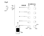
- Whether or not the road is an icy road may be determined by determining the unevenness of the road surface. That is, the water surface has a smooth flat surface or a spherical surface smooth due to surface tension, whereas the frozen surface has an uneven surface that is not smooth due to ice pellets. Therefore, in addition to the absolute displacement of the road surface condition, or without using the absolute displacement of the road surface condition, the information of the change pixel whose brightness value changes according to the relative displacement of the road surface condition with respect to the traveling vehicle is used. It may be determined whether or not the road is a frozen road. As shown in FIG. 8, concave DO and convex PO are present on the surface of the icy road. As shown in FIG.
- the displacement of the change pixels DO1 and PO1 schematically shows the displacement observed when the own vehicle M0 passes each position indicated by the arrow on the right side of the object DO and PO.
- the positions of the changing pixels DO1 and PO1 are displaced because the contours DO2 and PO2 of the objects DO and PO shown by the broken lines appear to be deformed according to the distance from the own vehicle M0, but in FIG.
- the deformation of the contours DO2 and PO2 of the objects DO and PO is not shown for the purpose of showing the displacement of the change pixels DO1 and PO1 with respect to the own vehicle M0.
- the road surface condition when it is determined that the road surface condition is at least one of a convex road surface and a concave road surface, it can be determined that the road surface condition is an icy road.
- the relative displacement of the road surface condition with respect to the traveling vehicle in addition to the determination using the absolute displacement of the road surface condition, it is possible to improve the accuracy of determining that the road surface condition is an icy road.
- the road surface condition when the road surface condition is wet, the displacement due to running water does not appear as the relative displacement of the road surface condition with respect to the traveling vehicle. Therefore, by using the relative displacement of the road surface condition with respect to the traveling vehicle, the road surface condition is used. Can improve the accuracy of determining that is a wet road.
- the determination that the road surface condition is an icy road may be determined when the icy road determination is continued over a predetermined distance, or freezing such as an intersection or a northern road surface is likely to occur, or It may be carried out in consideration of the characteristics of the road topography in which frozen roads are likely to be generated.
- the road surface condition determination device 100 determines the road surface when the position of the change pixel PO1 corresponding to the object PO moves away from the own vehicle M0 as the own vehicle M0 advances.
- the type of the road surface state is concave.
- the road surface By determining that the road surface is depressed, it can be determined whether or not the road surface is depressed or raised. Further, since the displacement of the changing pixel becomes larger as the concave portion or the convex portion becomes larger, the size of the concave portion or the convex portion can be determined.
- the driving support for the depressed / raised road a process of avoiding the depressed portion or the raised portion by steering support or reducing the speed of the own vehicle M0 by braking support or acceleration limitation can be executed.
- the wet path and the frozen path are determined by using the running water and the displacement of the running water layer.
- the type of road surface condition may be determined by acquiring the absolute displacement of the object for snow or sand on the road surface.
- snow and sand on the road surface move horizontally due to wind and running wind. Therefore, when it is determined to be a dry road in step S104 of FIG. 3, the amount of snow or sand on the road surface is determined by using the first detection signal output from the event camera 261 to determine the road surface condition.
- a snowfall road, a snowy road, or a sandy road may be determined.
- Snowy roads and sandy roads have a high degree of whiteness and may be determined to be dry roads by the camera 22, and generally, since they have a higher degree of whiteness than dry roads, they are determined to be snowy roads or sandy roads. Then, the displacement characteristic of the object may be used to determine whether the road is a snowy road or a sandy road. Since snowy roads and sandy roads are slippery, as driving support for snowy roads and sandy roads, the speed of the own vehicle M0 is suppressed by braking support or acceleration limitation, sudden acceleration / deceleration is suppressed, and braking start timing is set. Driving assistance that accelerates can be implemented.
- a control unit that executes the driving support process and the road surface condition determination process by software is realized by executing the driving support program Pr1 and the road surface condition determination program Pr2 by the CPU 101.
- the controls and methods thereof described in the present disclosure consist of a combination of a processor and memory programmed to perform one or more functions and a processor composed of one or more hardware logic circuits. It may be realized by one or more dedicated computers. Further, the computer program may be stored in a computer-readable non-transitional tangible recording medium as an instruction executed by the computer.
Landscapes
- Engineering & Computer Science (AREA)
- Physics & Mathematics (AREA)
- General Physics & Mathematics (AREA)
- Theoretical Computer Science (AREA)
- Computer Vision & Pattern Recognition (AREA)
- Mechanical Engineering (AREA)
- Transportation (AREA)
- Mathematical Physics (AREA)
- Automation & Control Theory (AREA)
- Quality & Reliability (AREA)
- Traffic Control Systems (AREA)
- Control Of Driving Devices And Active Controlling Of Vehicle (AREA)
- Image Analysis (AREA)
Priority Applications (2)
| Application Number | Priority Date | Filing Date | Title |
|---|---|---|---|
| DE112020001535.1T DE112020001535T5 (de) | 2019-03-25 | 2020-02-07 | Fahrbahnoberflächenzustands-bestimmungsvorrichtung für fahrzeuge, fahrassistenzsystem und fahrbahnoberflächenzustands-bestimmungsverfahren |
| US17/483,650 US11970171B2 (en) | 2019-03-25 | 2021-09-23 | Road surface condition determination device for vehicle, driving assistance system, and road surface condition determination method |
Applications Claiming Priority (2)
| Application Number | Priority Date | Filing Date | Title |
|---|---|---|---|
| JP2019056506A JP7120109B2 (ja) | 2019-03-25 | 2019-03-25 | 車両における路面状態判定装置、運転支援システムおよび路面状態判定方法 |
| JP2019-056506 | 2019-03-25 |
Related Child Applications (1)
| Application Number | Title | Priority Date | Filing Date |
|---|---|---|---|
| US17/483,650 Continuation US11970171B2 (en) | 2019-03-25 | 2021-09-23 | Road surface condition determination device for vehicle, driving assistance system, and road surface condition determination method |
Publications (1)
| Publication Number | Publication Date |
|---|---|
| WO2020195231A1 true WO2020195231A1 (ja) | 2020-10-01 |
Family
ID=72610761
Family Applications (1)
| Application Number | Title | Priority Date | Filing Date |
|---|---|---|---|
| PCT/JP2020/004840 Ceased WO2020195231A1 (ja) | 2019-03-25 | 2020-02-07 | 車両における路面状態判定装置、運転支援システムおよび路面状態判定方法 |
Country Status (4)
| Country | Link |
|---|---|
| US (1) | US11970171B2 (https=) |
| JP (1) | JP7120109B2 (https=) |
| DE (1) | DE112020001535T5 (https=) |
| WO (1) | WO2020195231A1 (https=) |
Cited By (4)
| Publication number | Priority date | Publication date | Assignee | Title |
|---|---|---|---|---|
| US20220185292A1 (en) * | 2020-12-11 | 2022-06-16 | Toyota Jidosha Kabushiki Kaisha | Update system for related value information and update method for related value information |
| CN114802259A (zh) * | 2021-01-19 | 2022-07-29 | 北京隐空科技有限公司 | 基于柔性轨道进路式点阵结构的无人驾驶控制系统及方法 |
| CN116295227A (zh) * | 2023-05-25 | 2023-06-23 | 湖南联智科技股份有限公司 | 一种路面平整度检测的方法、系统及存储介质 |
| US12441303B2 (en) | 2022-11-30 | 2025-10-14 | Bendix Commercial Vehicle Systems Llc | Systems and method for controlling driver assistance features of a vehicle based on images of a road surface condition |
Families Citing this family (13)
| Publication number | Priority date | Publication date | Assignee | Title |
|---|---|---|---|---|
| WO2021144029A1 (en) * | 2020-01-17 | 2021-07-22 | Volvo Truck Corporation | A cruise control system and a method for controlling a powertrain |
| CN111369709A (zh) * | 2020-04-03 | 2020-07-03 | 中信戴卡股份有限公司 | 行车场景确定方法、装置、计算机、存储介质及系统 |
| JP7279689B2 (ja) * | 2020-06-16 | 2023-05-23 | トヨタ自動車株式会社 | データ処理装置及びデータ処理システム |
| CN114822014B (zh) * | 2021-01-19 | 2023-11-03 | 北京隐空科技有限公司 | 基于柔性轨道进路式点阵结构的区域检测系统及方法 |
| KR20220111761A (ko) * | 2021-02-01 | 2022-08-10 | 주식회사 에이치엘클레무브 | 운전자 보조 장치 및 운전자 보조 방법 |
| JP7655760B2 (ja) * | 2021-03-31 | 2025-04-02 | 株式会社Subaru | 車両の走行制御装置 |
| IT202200003239A1 (it) * | 2022-02-22 | 2023-08-22 | Pirelli | Metodo e sistema di controllo di un veicolo in presenza di acquaplano |
| CN118810702B (zh) * | 2023-04-18 | 2026-02-10 | 比亚迪股份有限公司 | 一种车辆自动紧急制动的控制方法、电子设备及车辆 |
| CN116862164A (zh) * | 2023-07-04 | 2023-10-10 | 无锡惠友信息科技有限公司 | 智慧园区数字孪生系统 |
| CN117422699B (zh) * | 2023-11-10 | 2024-10-11 | 河北鹏鹄信息科技有限公司 | 公路检测方法、装置、计算机设备及存储介质 |
| CN117587680B (zh) * | 2023-11-20 | 2026-03-20 | 北京工业大学 | 一种路面跳车快速智能检测设备及检测方法 |
| CN119308204B (zh) * | 2024-12-11 | 2025-03-18 | 山东长中建筑工程有限公司 | 一种用于公路施工的路面基层测量装置 |
| CN119392577B (zh) * | 2024-12-30 | 2025-03-25 | 安徽建工建设投资集团有限公司 | 一种路基路面施工厚度检测方法 |
Citations (3)
| Publication number | Priority date | Publication date | Assignee | Title |
|---|---|---|---|---|
| WO2005075959A1 (ja) * | 2004-02-10 | 2005-08-18 | Nihon University | 摩擦係数推定方法及び装置 |
| JP2008269097A (ja) * | 2007-04-17 | 2008-11-06 | Nippon Telegr & Teleph Corp <Ntt> | 水面波挙動検出装置、水面波挙動検出方法、及び、水面波挙動検出プログラム |
| JP2009053818A (ja) * | 2007-08-24 | 2009-03-12 | Toshiba Corp | 画像処理装置及びその方法 |
Family Cites Families (7)
| Publication number | Priority date | Publication date | Assignee | Title |
|---|---|---|---|---|
| JP4315138B2 (ja) | 2004-09-13 | 2009-08-19 | ソニー株式会社 | 画像処理装置及び画像処理方法 |
| EP1897706B1 (en) * | 2005-06-17 | 2014-12-24 | Kabushiki Kaisha Bridgestone | Road surface state estimating method, road surface state estimating tire, road surface state estimating device, and vehicle control device |
| JP5436442B2 (ja) * | 2008-10-30 | 2014-03-05 | 株式会社ブリヂストン | 路面状態推定方法 |
| JP5657917B2 (ja) * | 2010-05-19 | 2015-01-21 | 株式会社ブリヂストン | 路面状態推定方法 |
| JP2017182139A (ja) | 2016-03-28 | 2017-10-05 | パナソニックIpマネジメント株式会社 | 判定装置、判定方法、および判定プログラム |
| DE102016210056A1 (de) | 2016-06-08 | 2017-12-14 | Robert Bosch Gmbh | Kameraanordnung zur Bestimmung des optischen Flusses, Fahrassistenzsystem und Überwachungskamera mit der Kameraanordnung |
| JP7017891B2 (ja) | 2017-09-20 | 2022-02-09 | 大和ハウス工業株式会社 | 空調システム |
-
2019
- 2019-03-25 JP JP2019056506A patent/JP7120109B2/ja active Active
-
2020
- 2020-02-07 DE DE112020001535.1T patent/DE112020001535T5/de active Pending
- 2020-02-07 WO PCT/JP2020/004840 patent/WO2020195231A1/ja not_active Ceased
-
2021
- 2021-09-23 US US17/483,650 patent/US11970171B2/en active Active
Patent Citations (3)
| Publication number | Priority date | Publication date | Assignee | Title |
|---|---|---|---|---|
| WO2005075959A1 (ja) * | 2004-02-10 | 2005-08-18 | Nihon University | 摩擦係数推定方法及び装置 |
| JP2008269097A (ja) * | 2007-04-17 | 2008-11-06 | Nippon Telegr & Teleph Corp <Ntt> | 水面波挙動検出装置、水面波挙動検出方法、及び、水面波挙動検出プログラム |
| JP2009053818A (ja) * | 2007-08-24 | 2009-03-12 | Toshiba Corp | 画像処理装置及びその方法 |
Cited By (6)
| Publication number | Priority date | Publication date | Assignee | Title |
|---|---|---|---|---|
| US20220185292A1 (en) * | 2020-12-11 | 2022-06-16 | Toyota Jidosha Kabushiki Kaisha | Update system for related value information and update method for related value information |
| US11904864B2 (en) * | 2020-12-11 | 2024-02-20 | Toyota Jidosha Kabushiki Kaisha | Update system for related value information and update method for related value information |
| CN114802259A (zh) * | 2021-01-19 | 2022-07-29 | 北京隐空科技有限公司 | 基于柔性轨道进路式点阵结构的无人驾驶控制系统及方法 |
| US12441303B2 (en) | 2022-11-30 | 2025-10-14 | Bendix Commercial Vehicle Systems Llc | Systems and method for controlling driver assistance features of a vehicle based on images of a road surface condition |
| CN116295227A (zh) * | 2023-05-25 | 2023-06-23 | 湖南联智科技股份有限公司 | 一种路面平整度检测的方法、系统及存储介质 |
| CN116295227B (zh) * | 2023-05-25 | 2023-07-28 | 湖南联智科技股份有限公司 | 一种路面平整度检测的方法、系统及存储介质 |
Also Published As
| Publication number | Publication date |
|---|---|
| JP2020157804A (ja) | 2020-10-01 |
| JP7120109B2 (ja) | 2022-08-17 |
| US20220009502A1 (en) | 2022-01-13 |
| US11970171B2 (en) | 2024-04-30 |
| DE112020001535T5 (de) | 2021-12-09 |
Similar Documents
| Publication | Publication Date | Title |
|---|---|---|
| JP7120109B2 (ja) | 車両における路面状態判定装置、運転支援システムおよび路面状態判定方法 | |
| US11919511B2 (en) | Driving support control device for vehicle, driving support system, and driving support method | |
| US11834039B2 (en) | Falling object determination device, driving support system, and falling object determination method | |
| US11097724B2 (en) | Apparatus and system for controlling travel of vehicle | |
| JP7111454B2 (ja) | 制御対象車両設定装置、制御対象車両設定システムおよび制御対象車両設定方法 | |
| US10745004B2 (en) | Object recognizing device and collision avoidance system | |
| JP5914524B2 (ja) | 3dカメラによる摩擦係数推定 | |
| US9594964B2 (en) | Vision-based wet road surface detection using texture analysis | |
| US20190041849A1 (en) | Monitor device | |
| CN110799387B (zh) | 车辆中的制动辅助装置以及制动辅助控制方法 | |
| US20190092326A1 (en) | Vehicle control apparatus | |
| US20190057272A1 (en) | Method of detecting a snow covered road surface | |
| US20210323545A1 (en) | Driver assistance apparatus | |
| JP7191143B2 (ja) | 他車両行動予測装置、他車両行動予測方法、及び自動運転システム | |
| US12065134B2 (en) | Wheel well mounted depth sensors for tire monitoring | |
| JP7111634B2 (ja) | 車両における対象物検出装置、対象物検出システムおよび対象物検出方法 | |
| CN113573965B (zh) | 用于为运输工具求取由潮湿引起的事故风险的方法 | |
| JP7243452B2 (ja) | 車両における物体検出装置、および車両における物体検出方法 | |
| CN114670817A (zh) | 车辆及其控制方法 | |
| US20240132052A1 (en) | Vehicle travel control device | |
| RU2814813C1 (ru) | Устройство и способ для отслеживания объектов | |
| RU2806452C1 (ru) | Устройство и способ для определения объектов | |
| RU2809334C1 (ru) | Беспилотное транспортное средство и способ управления его движением | |
| KR102915610B1 (ko) | 앙상블 기반 자동차 탐지 정확도-속도 트레이드오프 개선 방법 및 시스템 | |
| JP2020047177A (ja) | 車両における対象物特定装置、対象物特定システムおよび対象物特定方法 |
Legal Events
| Date | Code | Title | Description |
|---|---|---|---|
| 121 | Ep: the epo has been informed by wipo that ep was designated in this application |
Ref document number: 20776596 Country of ref document: EP Kind code of ref document: A1 |
|
| 122 | Ep: pct application non-entry in european phase |
Ref document number: 20776596 Country of ref document: EP Kind code of ref document: A1 |