WO2020195134A1 - 延長カテーテル - Google Patents
延長カテーテル Download PDFInfo
- Publication number
- WO2020195134A1 WO2020195134A1 PCT/JP2020/003217 JP2020003217W WO2020195134A1 WO 2020195134 A1 WO2020195134 A1 WO 2020195134A1 JP 2020003217 W JP2020003217 W JP 2020003217W WO 2020195134 A1 WO2020195134 A1 WO 2020195134A1
- Authority
- WO
- WIPO (PCT)
- Prior art keywords
- notch
- mass
- radiation opaque
- outer layer
- opaque substance
- Prior art date
- Legal status (The legal status is an assumption and is not a legal conclusion. Google has not performed a legal analysis and makes no representation as to the accuracy of the status listed.)
- Ceased
Links
Images




Classifications
-
- A—HUMAN NECESSITIES
- A61—MEDICAL OR VETERINARY SCIENCE; HYGIENE
- A61M—DEVICES FOR INTRODUCING MEDIA INTO, OR ONTO, THE BODY; DEVICES FOR TRANSDUCING BODY MEDIA OR FOR TAKING MEDIA FROM THE BODY; DEVICES FOR PRODUCING OR ENDING SLEEP OR STUPOR
- A61M25/00—Catheters; Hollow probes
-
- A—HUMAN NECESSITIES
- A61—MEDICAL OR VETERINARY SCIENCE; HYGIENE
- A61M—DEVICES FOR INTRODUCING MEDIA INTO, OR ONTO, THE BODY; DEVICES FOR TRANSDUCING BODY MEDIA OR FOR TAKING MEDIA FROM THE BODY; DEVICES FOR PRODUCING OR ENDING SLEEP OR STUPOR
- A61M25/00—Catheters; Hollow probes
- A61M25/01—Introducing, guiding, advancing, emplacing or holding catheters
- A61M25/06—Body-piercing guide needles or the like
Definitions
- the present invention relates to an extension catheter.
- ischemic heart disease such as angina and myocardial infarction
- percutaneous coronary artery formation that dilates the narrowed part of the coronary artery of the heart and increases blood flow using an intravascular treatment device such as a stent or balloon.
- Art is being performed.
- the tip of the tubular guiding catheter is inserted into the entrance of the coronary artery and placed, and then the endovascular treatment device is delivered through the guiding catheter to insert the endovascular treatment device into the peripheral side of the coronary artery.
- I was improving my sex.
- the backup force is small and the indwelling is unstable, the tip of the guiding catheter may come off from the entrance of the coronary artery. In that case, the backup force was improved by inserting a small-diameter extension catheter into the guiding catheter and projecting it from the distal opening of the guiding catheter.
- extension catheters for example, a proximal member including an extension portion of Patent Document 1, a collar member attached to the extension portion, and a distal sheath member attached to the collar member.
- Guide extension catheters with are known.
- a distal shaft forming the distal end side portion of Patent Document 2 and a proximal shaft forming the proximal end side portion are provided, and the proximal shaft is connected to the proximal end side portion of the distal shaft with a modified polyolefin adhesive.
- support catheters There are known support catheters.
- a coaxial guide catheter that can be delivered through the guide catheter by using the guide wire rail segment of Patent Document 3, the tip sheath of Patent Document 4, the proximal shaft, and the distal sheath on the proximal shaft.
- Guide extension catheters are known that include a coupling member to be immobilized.
- Patent Document 5 includes a balloon, an inner shaft joined to the tip of the balloon, a buffer film made of resin that covers the outer periphery of the inner shaft, and a metal that covers the outer periphery of the buffer film.
- a balloon catheter including a metal marker composed of a metal marker and a marker portion composed of the marker portion is disclosed.
- the position in the body is determined by X-ray fluoroscopy or the like.
- a radiation opaque substance was used for confirmation.
- an endovascular treatment device such as a stent or a balloon into an extension catheter in the body
- the opening on the proximal side of the extension catheter has a notched shape such as a taper shape, the position of the opening is difficult to understand, and it is often difficult to insert an endovascular treatment instrument into the extension catheter.
- the present invention has been made by paying attention to the above-mentioned problems, and an object of the present invention is to provide an extension catheter in which an endovascular treatment instrument can be easily inserted in the body.
- the extension catheter according to the present invention that has been able to solve the above problems is as follows.
- An extension catheter that can be inserted into a tubular catheter and protrudes from the distal opening of the tubular catheter. Equipped with a tubular member
- the tubular member has a tubular portion having a shape in which the radial cross-sectional shape is continuous in the circumferential direction, and a tubular portion having a radial cross-sectional shape continuous in the circumferential direction on the proximal side of the tubular portion.
- the tubular portion has a reinforcing portion provided with a reinforcing member and a non-reinforcing portion not provided with the reinforcing member proximal to the reinforcing portion.
- the non-reinforcing portion is an extension catheter characterized by containing a first radiation opaque substance.
- the notch has a first notch having a first notch surface having an angle formed by the tubular member with the axial direction of 90 ° or more and less than 175 °, and the first cut.
- the extension catheter according to [1], wherein the notch contains a second radiation opaque substance.
- the content (mass%) of the first radiation opaque substance in the outer layer of the non-reinforcing portion is 50% by mass or more and 90% by mass or less according to any one of [3] to [5].
- Extension catheter. [7] The extension catheter according to [4] or [5], wherein the content (mass%) of the second radiation opaque substance in the outer layer of the first notch is 40% by mass or less.
- the notch portion further forms a second notch portion having a second notch surface having an angle formed by the tubular member with the axial direction of ⁇ 5 ° or more and 5 ° or less.
- the extension catheter according to any one of [2] to [8], which is provided proximal to the notch.
- the extension catheter according to [10] The extension catheter according to [9], wherein the second notch portion contains a third radiation opaque substance.
- the extension catheter according to any one of [3] to [7], which is 10% by mass or more higher than the content (mass%) of the radiation opaque substance.
- a region not containing a radiation opaque substance is present in at least one portion selected from the group consisting of the reinforcing portion and the notched portion.
- the extension catheter described. [16] The extension catheter according to any one of [1] to [15], wherein the first radiation opaque substance is at least one selected from the group consisting of tungsten and barium salt. [17] The extension catheter according to any one of [2] to [14] and [16], wherein the second radiation opaque substance is at least one selected from the group consisting of tungsten and barium salt. [18] The extension catheter according to any one of [10] to [12], wherein the third radiation opaque substance is at least one selected from the group consisting of tungsten and barium salt.
- the present invention can provide an extension catheter in which an endovascular treatment instrument can be easily inserted in the body.
- FIG. 1 is a side view of an extension catheter according to an embodiment of the present invention.
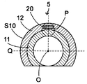
- FIG. 2 is a sectional view taken along line II-II of FIG.
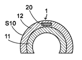
- FIG. 3 is a sectional view taken along line III-III of FIG.
- FIG. 4 is a sectional view taken along line IV-IV of FIG.
- FIG. 5 is a sectional view taken along line VV of FIG.
- FIG. 6 is an axial cross-sectional view of the R portion of FIG.
- FIG. 7 is a diagram showing a state when the extension catheter according to the embodiment of the present invention is inserted into the tubular catheter and protrudes from the distal opening of the tubular catheter.
- the extension catheter of the present invention is an extension catheter that is inserted into a tubular catheter and can protrude from an opening on the distal side of the tubular catheter, and includes a tubular member, and the tubular member is radial.
- a tubular portion having a shape in which the cross-sectional shape is continuous in the circumferential direction and a notch portion having a shape in which the cross-sectional shape in the radial direction is not continuous in the circumferential direction on the proximal side of the tubular portion.
- the tubular portion has a reinforcing portion provided with a reinforcing member and a non-reinforcing portion not provided with the reinforcing member proximal to the reinforcing portion, and the non-reinforcing portion is provided.
- the section contains the first radiation opaque material.
- the non-reinforcing portion of the tubular portion contains the first radiation opaque substance, the position of the non-reinforcing portion in the body such as under fluoroscopy can be easily confirmed. It is possible to easily grasp the position of the notch portion located on the proximal side of the non-reinforcing portion. As a result, it is possible to easily insert an endovascular treatment instrument such as a stent or a balloon into the extension catheter through the notch in the body.
- containing the radioactive impermeable substance is not only when the radioactive impermeable substance is mixed and present in the non-reinforcing portion, but also when the radioactive impermeable substance is present independently on the surface of the non-reinforcing portion. Including the case of doing.
- FIG. 1 is a side view of an extension catheter according to an embodiment of the present invention.
- FIG. 2 is a sectional view taken along line II-II of FIG.
- FIG. 3 is a sectional view taken along line III-III of FIG.
- FIG. 4 is a sectional view taken along line IV-IV of FIG.
- FIG. 5 is a sectional view taken along line VV of FIG.
- FIG. 6 is an axial cross-sectional view of the R portion of FIG.
- FIG. 7 is a diagram showing a state when the extension catheter according to the embodiment of the present invention is inserted into the tubular catheter and protrudes from the distal opening of the tubular catheter.
- the extension catheter 30 is an extension catheter that can be inserted into a tubular catheter 40 as shown in FIG. 7, and can protrude from an opening a40 on the distal side of the tubular catheter 40, for example. Is.
- the extension catheter 30 includes a tubular member 10.
- the tubular member 10 has a tubular portion 4 and a notch portion 3 located proximal to the tubular portion 4.
- the radial cross-sectional shape of the tubular portion 4 is a shape that is continuous in the circumferential direction as shown in FIGS. 2 and 5, that is, a shape in which at least the inner side surface of the tubular portion 4 is continuous.
- the cross-sectional shape of the notch portion 3 in the radial direction is a shape that is not continuous in the circumferential direction as shown in FIG.
- the tubular portion 4 is not provided with the reinforcing portion 6 provided with the reinforcing member 13 and the reinforcing member 13 proximal to the reinforcing portion 6. It has a non-reinforcing portion 5.
- the non-reinforcing portion 5 of the tubular portion 4 contains a first radiation opaque substance.
- the cutout portion 3 is a portion that is more difficult to confirm in the body than the tubular portion 4 due to the cutout portion, but the non-reinforcing portion 5 contains the first radiation opaque substance, so that the non-reinforcing portion 5 Since the radiation impermeableness of the non-reinforcing portion 5 becomes high, the non-reinforcing portion 5 can function as a mark. This makes it easier to grasp the position of the notch 3 proximal to the mark, so that an endovascular treatment instrument such as a stent or balloon is inserted into the extension catheter 30 through the notch 3 in the body. It can be made easier.
- the proximal side means the direction toward the operator's hand side with respect to the extending direction of the extension catheter 30, and the direction opposite to the distal side, that is, the treatment. It means the direction of the target side.
- the extension catheter 30 is inserted into the tubular catheter 40, for example, through the opening b40 on the proximal side of the tubular catheter 40 shown in FIG. 7.
- the tubular catheter 40 has a distal end A40 and a proximal end B40, and the distal end A40 and the proximal end B40 are provided with openings a40 and b40, respectively.
- the tubular catheter 40 may be a guiding catheter.
- the extension catheter 30 has a distal end A30, and the distal end A30 of the extension catheter 30 is inserted through the proximal opening b40 of the tubular catheter 40. As shown in FIG.
- the distal portion of the extension catheter 30 can be projected from the opening a40 on the distal side of the tubular catheter 40, or can be pulled back.
- the extension catheter 30 is inserted into the tubular catheter 40 which is previously arranged in the body cavity, and the device passing through the tubular catheter 40 and the extension catheter 30 is made to reach the distal side in the body cavity. Used.
- the inner diameter of the tubular catheter 40 is larger than the outer diameter of the extension catheter 30 in order to receive the extension catheter 30 into the lumen.
- the extension catheter 30 preferably has a shape in which a tubular member 10 including a tubular portion 4 and a notch portion 3 on the distal side and a rod-shaped linear member 20 are connected. As shown in FIG.
- the linear member 20 of the extension catheter 30 is preferably used without protruding from the opening a40 on the distal side of the tubular catheter 40.
- the length of the extension catheter 30 can be, for example, 1500 mm, and the length of the tubular member 10 of the extension catheter 30 can be, for example, 350 mm.
- the diameter of the distal end of the tubular member 10 of the extension catheter 30 can be, for example, 1.5 mm.
- the device for treatment enters the tubular catheter 40 through the proximal opening b40 of the tubular catheter 40, enters the extension catheter 30 through the proximal opening of the extension catheter 30, and enters the extension catheter 30 distally. It can protrude from the opening a30 of.
- the reinforcing portion 6 is a portion of the tubular portion 4 where the reinforcing member 13 is provided.
- the reinforcing member 13 can easily improve the kink resistance of the tubular portion 4, that is, the bending resistance, and as a result, it is possible to easily hold the lumen of the tubular portion 4.
- the reinforcing member 13 is not limited to the inside of the outer layer 12 of the tubular portion 4 described later, and may be provided in the inner layer 11 or between the inner layer 11 and the outer layer 12. Of these, if the reinforcing member 13 is provided in the outer layer 12, the kink resistance is likely to be improved. Therefore, it is preferable that the reinforcing member 13 is provided in the outer layer 12.
- Examples of the material constituting the reinforcing member 13 include metal wire and fiber.
- As the material constituting the metal wire for example, stainless steel, titanium, nickel-titanium alloy, cobalt-chromium alloy and the like, tungsten alloy and the like are preferable. Of these, stainless steel is more preferable.
- the metal wire may be a single wire or a stranded wire.
- Examples of the fiber include polyarylate fiber, aramid fiber, ultra-high molecular weight polyethylene fiber, PBO fiber, carbon fiber and the like.
- the fibers may be monofilaments or multifilaments.
- the shape of the reinforcing member 13 is not particularly limited, but a spiral shape, a mesh shape, or a braided shape is preferable. Of these, the braided shape tends to improve the kink resistance of the tubular portion 4, so that the shape of the reinforcing member 13 is more preferably braided.
- the reinforcing member 13 may contain a radiation opaque substance in order to make it easier to confirm the position of the tubular portion 4 under fluoroscopy or the like.
- a radiation opaque substance the first radiation opaque substance or the like described later can be referred to.
- the non-reinforcing portion 5 is a portion of the tubular portion 4 located proximal to the reinforcing portion 6 and not provided with the reinforcing member 13.
- the non-reinforcing portion 5 contains a first radiation opaque substance.
- the first radiation opaque substance may be inorganic fine particles, as long as the position of the non-reinforcing portion 5 in the body can be easily understood under fluoroscopy or the like.
- a material for the inorganic fine particles at least one selected from the group consisting of tungsten, barium salt, lead, barium, iodine, gold, platinum, iridium, platinum iridium alloy, stainless steel, titanium, cobalt-chromium alloy, palladium, and tantalum is selected.
- at least one selected from the group consisting of tungsten, barium salt, lead, and tantalum is more preferable, at least one selected from the group consisting of tungsten and barium salt is further preferable, and tungsten is particularly preferable. ..
- barium salt at least one selected from the group consisting of barium sulfate, barium carbonate, barium hydroxide, barium chloride, barium nitrate, and barium acetate is preferable. Of these, barium sulfate is more preferable.
- the first radiation opaque substance preferably contains an element having an atomic number of 20 or more. Since the radiation opacity of a substance tends to increase as the atomic weight increases, the radiation opacity can be improved by containing an element having an atomic number of 20 or more. Therefore, the first radiation impermeable substance more preferably contains an element having an atomic number of 30 or more, and further preferably contains an element having an atomic number of 40 or more. On the other hand, the upper limit of the atomic number of the element contained in the first radiation opaque substance may be, for example, 82 or less, 79 or less, or 74 or less.
- the average particle size of the first radiation opaque substance is preferably 100 nm or more and 100 ⁇ m or less.
- the average particle size is more preferably 500 nm or more, still more preferably 1 ⁇ m or more.
- the average particle size is more preferably 50 ⁇ m or less, still more preferably 20 ⁇ m or less.
- D50 median size of particle size distribution
- the non-reinforcing portion 5 preferably includes an inner layer 11 and an outer layer 12 as shown in FIGS. 2 and 6.
- the first radiation opaque substance is preferably contained in the outer layer 12 of the non-reinforcing portion 5.
- the position of the non-reinforcing portion 5 under fluoroscopy or the like becomes easy to understand, so that the position of the notch portion 3 located proximal to the non-reinforcing portion 5 can be easily grasped.
- the inner layer 11 of the non-reinforcing portion 5 may also contain the first radiation opaque substance.
- Resin can be mentioned as a material constituting the inner layer 11 of the non-reinforcing portion 5.
- the resin for example, at least one selected from the group consisting of polyamide-based resin, polyester-based resin, polyurethane-based resin, polyolefin-based resin, fluorine-based resin, vinyl chloride-based resin, silicone-based resin, and natural rubber is preferable. Of these, at least one selected from the group consisting of polyester-based resins, polyolefin-based resins, fluororesins, silicone-based resins, and natural rubber is more preferable. Of these, fluororesins are particularly preferable because they are excellent in chemical resistance, non-adhesiveness, and low friction.
- polyamide resin examples include nylon 12, nylon 12 elastomer, nylon 6, aromatic polyamide and the like.
- polyester resin examples include polyethylene terephthalate and the like.
- polyurethane-based resin examples include an aliphatic polyurethane containing an aliphatic isocyanate as a monomer unit and an aromatic polyurethane containing an aromatic isocyanate as a monomer unit.
- polyolefin resin examples include polyethylene and polypropylene.
- fluorine-based resin examples include polytetrafluoroethylene, ethylene tetrafluoroethylene, and fluorinated ethylene propylene. High-strength polytetrafluoroethylene is preferable as the polytetrafluoroethylene.
- Examples of the vinyl chloride resin include polyvinyl chloride and polyvinylidene chloride.
- Examples of the silicone-based resin include dimethylpolysiloxane, methylphenylpolysiloxane, methylvinylpolysiloxane, fluoroalkylmethylpolysiloxane, and the like.
- Examples of natural rubber include latex and the like.
- Resin can be mentioned as a material constituting the outer layer 12 of the non-reinforcing portion 5.
- the resin for example, at least one selected from the group consisting of polyamide-based resin, polyester-based resin, polyurethane-based resin, polyolefin-based resin, fluorine-based resin, vinyl chloride-based resin, silicone-based resin, and natural rubber is preferable.
- at least one selected from the group consisting of a polyamide resin, a polyurethane resin, and a polyolefin resin is more preferable, and at least one selected from the group consisting of a polyamide resin and a polyurethane resin is further preferable.
- Polyurethane-based resins are even more preferred.
- the outer surface S10 of the outer layer 12 of the non-reinforcing portion 5 is preferably coated with a hydrophilic polymer.
- a hydrophilic polymer examples include hydrophilic polymers such as maleic anhydride copolymers such as poly2-hydroxyethyl methacrylate, polyacrylamide, polyvinylpyrrolidone, and methyl vinyl ether maleic anhydride copolymers.
- the inner diameter of the non-reinforcing portion 5 is preferably 1.0 mm or more and 2.2 mm or less. Since the inner diameter of the non-reinforcing portion 5 is 2.2 mm or less, the shape of the non-reinforcing portion 5 is likely to be stable, so that the shape of the adjacent notch portion 3 is also easily stable. It is more preferably 2.0 mm or less, still more preferably 1.8 mm or less. On the other hand, by setting the inner diameter of the non-reinforcing portion 5 to 1.0 mm or more, the endovascular treatment instrument can easily pass through the non-reinforcing portion 5. It is more preferably 1.2 mm or more, still more preferably 1.4 mm or more.
- the outer diameter of the non-reinforcing portion 5 is preferably 1.2 mm or more and 3 mm or less. When the outer diameter of the non-reinforcing portion 5 is 3 mm or less, the non-reinforcing portion 5 can be easily inserted into the guiding catheter or the blood vessel. It is more preferably 2 mm or less, still more preferably 1.8 mm or less. On the other hand, by setting the outer diameter of the non-reinforcing portion 5 to 1.2 mm or more, it is possible to easily improve the strength of the non-reinforcing portion 5. It is more preferably 1.4 mm or more, still more preferably 1.6 mm or more.
- the non-reinforcing portion 5 preferably satisfies the following formula (1).
- D ⁇ L 3 ⁇ 6D ...
- L 3 indicates the axial length (mm) of the tubular portion 4 from the proximal end B5 to the distal end A5 of the non-reinforcing portion 5.
- D indicates the outer diameter (mm) of the non-reinforced portion 5 at a position 1 mm away from the proximal end B5 of the non-reinforced portion 5 on the distal side.
- the axial length L 3 of the cylindrical portion 4 from the proximal end B5 of unreinforced portion 5 to the distal end A5 is distally from the proximal end B5 of unreinforced portion 5
- the outer diameter D or more of the non-reinforcing portion 5 it is preferable that the outer diameter D or more of the non-reinforcing portion 5 at a position separated by 1 mm.
- L 3 is preferably 1.5 times or more of D, and more preferably 2 times or more of D.
- L 3 is 6 times or less of D, it is possible to easily avoid deformation of the non-reinforcing portion 5.
- L 3 is more preferably 4 times or less of D, and further preferably 3 times or less of D.
- L 3 is preferably 0.5 mm or more and 8 mm or less, more preferably 2 mm or more and 6 mm or less, and further preferably 3 mm or more and 5 mm or less.
- the notch portion 3 preferably has a first notch portion 1.
- the first notched portion 1 has a first notched surface S1 and an outer surface S10.
- the angle ⁇ 1 formed by the first cutout surface S1 and the axial direction X of the tubular member 10 is 90 ° or more and less than 175 °.
- ⁇ 1 is more preferably 140 ° or less, still more preferably 130 ° or less, and even more preferably 120 ° or less.
- ⁇ 1 is more preferably more than 90 °, still more preferably 95 ° or more, even more preferably 100 ° or more, and particularly preferably 110 ° or more.
- the radial cross-sectional shape of the outer surface S10 of the first notch 1 is from a circular arc with a large central angle as shown in FIG. 3 from the distal side to the proximal side of the first notch 1. It is preferable that the change is continuous in a circular arc with a small central angle as shown in FIG. By continuously changing in this way, it is possible to facilitate insertion of the endovascular treatment instrument from the opening of the first notch portion 1.
- the first notch portion 1 contains a second radiation opaque substance.
- the second radiation opaque substance may be inorganic fine particles, as long as the position of the first notch 1 in the body can be easily understood under fluoroscopy or the like.
- a material for the inorganic fine particles at least one selected from the group consisting of tungsten, barium salt, lead, barium, iodine, gold, platinum, iridium, platinum iridium alloy, stainless steel, titanium, cobalt-chromium alloy, palladium, and tantalum is selected.
- at least one selected from the group consisting of tungsten, barium salt, lead and tantalum is more preferable, and even more preferably at least one selected from the group consisting of tungsten and barium salt, especially barium salt. preferable.
- barium salt at least one selected from the group consisting of barium sulfate, barium carbonate, barium hydroxide, barium chloride, barium nitrate, and barium acetate is preferable. Of these, barium sulfate is more preferable as the barium salt.
- the second radiation opaque substance may contain, for example, an element having an atomic number of 20 or more and an element having an atomic number of 30 or more, an element having an atomic number of 82 or less, an element having an atomic number of 79 or less, and an atomic number. May contain elements of 74 or less.
- the average particle size of the second radiation opaque substance is preferably 100 nm or more and 100 ⁇ m or less.
- the average particle size is more preferably 500 nm or more, still more preferably 1 ⁇ m or more.
- the average particle size is more preferably 50 ⁇ m or less, still more preferably 20 ⁇ m or less.
- D50 median size of particle size distribution
- the second radiation opaque substance preferably has lower radiation opacity than the first radiation opaque substance. As a result, it is possible to facilitate the function as a mark for the first notched portion 1 of the non-reinforcing portion 5.
- the same substance as the first radiation opaque substance may be used. In this case, if the content (mass%) of the first radiation opaque substance in the non-reinforcing portion 5 is made larger than the content (mass%) of the second radiation opaque substance in the first notch portion 1. Good.
- the first cutout portion 1 includes an inner layer 11 and an outer layer 12 as shown in FIG.
- the second radiation opaque substance is preferably contained in the outer layer 12 of the first notch portion 1. This makes it easier to understand the shape of the first notch portion 1 under fluoroscopy or the like. Further, the inner layer 11 of the first notch portion 1 may also contain a second radiation opaque substance.
- the material constituting the inner layer 11 of the first notch portion 1 As the material constituting the inner layer 11 of the first notch portion 1, the material constituting the inner layer 11 of the non-reinforcing portion 5 can be referred to. Further, as the material constituting the outer layer 12 of the first notch portion 1, the material constituting the outer layer 12 of the non-reinforcing portion 5 can be referred to.
- the first notch portion 1 preferably satisfies the following formula (2). 0.3D ⁇ D 1 ... (2)
- D indicates the outer diameter (mm) of the non-reinforcing portion 5 at a position 1 mm away from the proximal end B5 of the non-reinforcing portion 5.
- D 1 indicates the radial length at the proximal end B1 of the first notch 1.
- the proximal end length D 1 of the radial direction in the B1 of the first cut-out portion 1 shown in FIG. 6, the outer non-reinforced portion 5 in 1mm away distally from the proximal end B5 of unreinforced portion 5 It is preferably 0.3 times or more the diameter D.
- D 1 is more preferably 0.4 times or more of D.
- D 1 is preferably 0.8 times or less of D.
- D 1 is more preferably 0.7 times or less of D, and further preferably 0.6 times or less of D.
- D 1 is preferably 0.2 mm or more and 2 mm or less, more preferably 0.5 mm or more and 1.5 mm or less, and further preferably 0.8 mm or more and 1.2 mm or less.
- D is preferably 0.5 mm or more and 4 mm or less, more preferably 1 mm or more and 2 mm or less, and further preferably 1.4 mm or more and 1.8 mm or less.
- L 1 is preferably 0.5 mm or more and 6 mm or less, more preferably 1 mm or more and 4 mm or less, and further preferably 1.5 mm or more and 3 mm or less.
- Radial length H 1 between the farthest point F1 closest point N1 to the center axis C of the cylindrical portion 4 of the first notch surface S1 is preferably 0.1mm or more, 1.5 mm or less, more preferably Is 0.2 mm or more and 1 mm or less, more preferably 0.4 mm or more and 0.7 mm or less.
- the content (mass%) of the first radiation opaque substance in the outer layer 12 of the non-reinforcing portion 5 is larger than the content (mass%) of the second radiation opaque substance in the outer layer 12 of the first notch portion 1. It is preferably 10% by mass or more. In this way, by increasing the content of the radiation opaque substance in the outer layer 12 of the non-reinforcing portion 5 than in the outer layer 12 of the first notch portion 1, the position of the non-reinforcing portion 5 in the body can be determined under fluoroscopy or the like. It can be easily confirmed. As a result, it is possible to easily exert the function as a mark for the first notched portion 1 of the non-reinforcing portion 5.
- the content (mass%) of the first radiation opaque substance in the outer layer 12 of the non-reinforcing portion 5 is larger than the content (mass%) of the second radiation opaque substance in the outer layer 12 of the first notch portion 1. It is more preferably 20% by mass or more, and further preferably 30% by mass or more.
- the upper limit of the difference in the content (mass%) is not particularly limited, but may be, for example, 70% by mass or less, 60% by mass or less, or 50% by mass or less.
- the content (mass%) of the first radiation opaque substance in the outer layer 12 of the non-reinforcing portion 5 is preferably 50% by mass or more and 90% by mass or less.
- the content (mass%) of the first radiation opaque substance in the outer layer 12 of the non-reinforcing portion 5 is 50% by mass or more, the position of the non-reinforcing portion 5 in the body can be easily understood under fluoroscopy or the like. be able to. Therefore, it is more preferably 55% by mass or more, further preferably 60% by mass or more, and even more preferably 65% by mass or more.
- the content (mass%) of the first radiation opaque substance in the outer layer 12 of the non-reinforcing portion 5 is 90% by mass or less, the flexibility of the non-reinforcing portion 5 can be easily improved. It is more preferably 85% by mass or less, further preferably 80% by mass or less, and even more preferably 75% by mass or less.
- the content (mass%) of the second radiation opaque substance in the outer layer 12 of the first notch portion 1 is preferably 40% by mass or less. As a result, it is possible to facilitate the function of the non-reinforcing portion 5 as a mark for the first notched portion 1. It is more preferably 35% by mass or less, still more preferably 30% by mass or less. On the other hand, by setting the content (mass%) of the second radiation opaque substance in the outer layer 12 of the first notch portion 1 to 5% by mass or more, it is easy to confirm the shape of the first notch portion 1. Can be done. It is preferably 5% by mass or more, more preferably 10% by mass or more, and further preferably 15% by mass or more.
- the mass of the linear member 20 described later shall be excluded.
- the non-reinforcing portion 5 includes a region having a higher radiation opacity than the first notched portion 1. As a result, it is possible to facilitate the function of the non-reinforcing portion 5 as a mark for the first notched portion 1. Further, it is preferable that the non-reinforcing portion 5 includes a region having a higher radiation opacity than the region on the distal side of the second notch portion 2 described later.
- the first notch 1 does not contain a radiation opaque substance while the non-reinforcing portion 5 Is a method of containing a first radiation opaque substance
- the first notch portion 1 contains a second radiation opaque substance
- the non-reinforcing portion 5 is more radiation than the second radiation opaque substance.
- Examples thereof include a method of containing a first radiation opaque substance having high opacity.
- the strength of radiation opacity for example, using an X-ray opaque device (OEC9800 SUP9 MD) manufactured by GE Yokogawa Medical System Co., Ltd., a voltage of 48 kVp, a current amount of 0.64 mA, and a time of 0.
- the strength of the radiation opacity can be determined by taking an X-ray image of the tubular member 10 under the condition of a dose of 0.25 mGy for 4 minutes and comparing the contrasts of the images.
- the tubular member 10 has the linear member 20 described later, the region excluding the linear member 20 is measured.
- the central portion P in the circumferential direction of the contact portion in contact with the first notch portion 1 and the shaft of the non-reinforcing portion 5
- the non-reinforcing portion 5 is divided into two by the plane Q passing through the axial center O of the non-reinforcing portion 5, which is a plane perpendicular to the straight line connecting the center O, the non-reinforcing portion 5 having no central portion P
- the content (mass%) of the first radiation opaque substance in the outer layer 12 is higher than the content (mass%) of the first radiation opaque substance in the outer layer 12 of the non-reinforcing portion 5 on which the central portion P is present.
- Is also preferably as high as 10% by mass or more, more preferably as high as 20% by mass or more, and further preferably as high as 30% by mass or more.
- the radiation opacity on the side where the central portion P does not exist, that is, on the opening side becomes high, so that the orientation of the first notch 1 under fluoroscopy or the like becomes easy to understand, and an endovascular treatment instrument is inserted. It can be made easier.
- the upper limit of the difference in the content (% by mass) is not particularly limited, but may be, for example, 90% by mass or less, 80% by mass or less, or 60% by mass or less. ..
- the central portion P in the circumferential direction of the contact portion in contact with the first notch portion 1 and the shaft of the non-reinforcing portion 5
- the non-reinforcing portion 5 is divided into two by the plane Q passing through the axial center O of the non-reinforcing portion 5, which is a plane perpendicular to the straight line connecting the center O, the non-reinforcing portion 5 on which the central portion P exists
- the outer layer 12 has a region that does not contain a radiation opaque substance. As a result, the orientation of the first notch portion 1 under fluoroscopy or the like becomes easy to understand, so that the endovascular treatment instrument can be easily inserted.
- the notch portion 3 preferably has a second notch portion 2 proximal to the first notch portion 1.
- the second notch portion 2 has a second notch surface S2 and an outer surface S10.
- the angle ⁇ 2 (not shown) formed by the second cutout surface S2 and the axial direction X of the tubular member 10 is ⁇ 5 ° or more and 5 ° or less.
- ⁇ 2 is ⁇ 5 ° or more and 5 ° or less.
- the endovascular treatment instrument is opened along the second notch 2. It can be easily inserted into the portion. It is more preferably -3 ° or more and 3 ° or less, further preferably -2 ° or more and 2 ° or less, and even more preferably -1 ° or more and 1 ° or less.
- the second notch portion 2 contains a third radiation opaque substance.
- the third radiation opaque substance may be inorganic fine particles, as long as the position of the second notch 2 in the body can be easily understood under fluoroscopy or the like.
- a material for the inorganic fine particles at least one selected from the group consisting of tungsten, barium salt, lead, barium, iodine, gold, platinum, iridium, platinum iridium alloy, stainless steel, titanium, cobalt-chromium alloy, palladium, and tantalum is selected.
- At least one selected from the group consisting of tungsten, barium salt, lead, and tantalum is more preferable, at least one selected from the group consisting of tungsten and barium salt is further preferable, and tungsten is particularly preferable. ..
- barium salt at least one selected from the group consisting of barium sulfate, barium carbonate, barium hydroxide, barium chloride, barium nitrate, and barium acetate is preferable. Of these, barium sulfate is more preferable as the barium salt.
- the third radiation impermeable substance may contain, for example, an element having an atomic number of 20 or more and an element having an atomic number of 30 or more, an element having an atomic number of 82 or less, an element having an atomic number of 79 or less, and an atomic number. May contain elements of 74 or less.
- the average particle size of the third radiation opaque substance is preferably 100 nm or more and 100 ⁇ m or less.
- the average particle size is more preferably 500 nm or more, still more preferably 1 ⁇ m or more.
- the average particle size is more preferably 50 ⁇ m or less, still more preferably 20 ⁇ m or less.
- D50 median size of particle size distribution
- the same substance as the first radiation opaque substance or the second radiation opaque substance may be used.
- the strength of the radiation opacity in each part may be controlled by increasing or decreasing the content (mass%) of the radiation opaque substance in each part.
- the second notch portion 2 preferably includes an inner layer 11 and an outer layer 12 as shown in FIG. It is preferable that the third radiation opaque substance is contained in the outer layer 12 of the second notch portion 2. This makes it easier to understand the position of the second notch portion 2 under fluoroscopy or the like. Further, the inner layer 11 of the second notch portion 2 may also contain a third radiation opaque substance.
- the material constituting the inner layer 11 of the second notch portion 2 the material constituting the inner layer 11 of the non-reinforcing portion 5 can be referred to. Further, as the material constituting the outer layer 12 of the second notch portion 2, the material constituting the outer layer 12 of the non-reinforcing portion 5 can be referred to.
- the second notch 2 (hereinafter, may be referred to as a proximal region of the second notch 2) from the proximal end B2 of the second notch 2 to a position 3 mm away from the distal side.
- the content (mass%) of the third radiation opaque substance in the outer layer 12 of) is the second notch 2 (hereinafter referred to as the second) from a position 3 mm away to the distal end A2 of the second notch 2. 2 It is preferable that the content is 10% by mass or more higher than the content (mass%) of the third radiation opaque substance in the outer layer 12 of the notch 2 (sometimes referred to as the distal region). Since the second notch 2 is notched, it is difficult to confirm it in the body.
- the second notch 2 is formed. 2 It is possible to easily confirm the position of the proximal end B2 of the notch portion 2. As a result, the endovascular treatment instrument can be easily inserted into the opening along the second notch 2. Therefore, the content (mass%) of the third radiation opaque substance in the outer layer 12 of the proximal region of the second notch 2 is the third in the outer layer 12 of the distal region of the second notch 2. It is more preferably 20% by mass or more higher than the content (mass%) of the radiation opaque substance, and further preferably 30% by mass or more. On the other hand, the upper limit of the difference in the content (mass%) is not particularly limited, but may be, for example, 90% by mass or less, 80% by mass or less, or 60% by mass or less. Good.
- the content (mass%) of the third radiation opaque substance in the outer layer 12 of the proximal region of the second notch 2 is preferably 50% by mass or more and 90% by mass or less.
- the content (mass%) of the third radiation opaque substance in the outer layer 12 in the proximal region of the second notch 2 is 50% by mass or more, the proximal end B2 of the second notch 2 It is possible to easily confirm the position of. Therefore, it is more preferably 55% by mass or more, further preferably 60% by mass or more, and even more preferably 65% by mass or more.
- the upper limit of the content (mass%) of the third radiation opaque substance in the outer layer 12 in the proximal region of the second notch 2 is not particularly limited, but may be, for example, 90% by mass or less. It may be 85% by mass or less, 80% by mass or less, or 75% by mass or less.
- the content (mass%) of the third radiation opaque substance in the outer layer 12 of the distal region of the second notch 2 is preferably 40% by mass or less.
- the proximal region of the second notch 2 Can be facilitated to function as a marker for the proximal end B2. It is more preferably 35% by mass or less, still more preferably 30% by mass or less.
- the shape of the second notch 2 can be changed. It can be easily confirmed. It is preferably 5% by mass or more, more preferably 10% by mass or more, and further preferably 15% by mass or more.
- the content (% by mass) of the first radiation opaque substance in the outer layer 12 of the non-reinforcing portion 5 is the content of the third radiation opaque substance in the outer layer 12 of the distal region of the second notch portion 2. It is preferably 10% by mass or more higher than (% by mass). In this way, by increasing the content of the radiation opaque substance in the outer layer 12 of the non-reinforcing portion 5 than in the outer layer 12 of the distal region of the second notch portion 2, the function as a mark of the non-reinforcing portion 5 is provided. It can be easily exerted.
- the content (% by mass) of the first radiation opaque substance in the outer layer 12 of the non-reinforcing portion 5 is the content of the third radiation opaque substance in the outer layer 12 of the distal region of the second notch portion 2. It is more preferably 20% by mass or more higher than (% by mass), and even more preferably 30% by mass or more.
- the upper limit of the difference in the content (mass%) is not particularly limited, but may be, for example, 70% by mass or less, 60% by mass or less, or 50% by mass or less.
- the second notch portion 2 preferably satisfies the following formula (3). 10D ⁇ L 2 ⁇ 200D ... (3)
- D indicates the outer diameter (mm) of the non-reinforcing portion 5 at a position 1 mm away from the proximal end B5 of the non-reinforcing portion 5.
- L 2 indicates the length (mm) of the tubular member 10 in the axial direction X from the distal end A2 of the second notch 2 to the proximal end B2 of the second notch 2.
- the length L 2 in the axial direction X of the tubular member 10 from the distal end A2 of the second cut-out portion 2 to the proximal end B2 of the second cut-out section 2, the proximal end B5 of unreinforced portion 5 It is preferably 10 times or more the outer diameter D of the non-reinforcing portion 5 at a position 1 mm away from the distal side.
- L 2 is more preferably 30 times or more the outer diameter D, and further preferably 60 times or more the outer diameter D.
- L 2 is preferably 200 times or less the outer diameter D. Thereby, the flexibility of the linear member 20 can be improved.
- L 2 is more preferably 120 times or less of the outer diameter D, and further preferably 90 times or less of the outer diameter D.
- L 2 is preferably 5 cm or more and 20 cm or less, more preferably 10 cm or more and 18 cm or less, and further preferably 12 cm or more and 15 cm or less.
- first notch portion 1 and the second notch portion 2 are adjacent to each other.
- a third notch (not shown) may be provided between the first notch 1 and the second notch 2.
- the third notched portion has a third notched surface and an outer surface. In this case, it is preferable that the first notch portion 1 and the third notch portion are adjacent to each other, and it is preferable that the third notch portion and the second notch portion 2 are adjacent to each other.
- the angle ⁇ 3 (not shown) formed by the third cutout surface and the axial direction X is preferably 120 ° or more. As a result, it is possible to easily increase the opening area of the opening for inserting the endovascular treatment instrument. Therefore, ⁇ 3 is more preferably 130 ° or more, still more preferably 140 ° or more, and even more preferably 150 ° or more. On the other hand, the upper limit of ⁇ 3 may be, for example, 175 °, 170 °, or 168 °.
- the axial length from the point farthest to the point closest to the central axis C of the tubular portion 4 of the third notched surface is preferably 0.5 mm or more, 6 mm or less, and more preferably 1 mm. It is 4 mm or less, more preferably 1.5 mm or more and 3 mm or less.
- the radial length of the point closest to the central axis C and the point farthest from the central axis C of the tubular portion 4 of the third cutout surface is preferably 0.1 mm or more, 1.5 mm or less, more preferably. Is 0.2 mm or more and 1 mm or less, more preferably 0.4 mm or more and 0.7 mm or less.
- At least one portion selected from the group consisting of the reinforcing portion 6 and the notched portion 3 has a region that does not contain a radiation opaque substance.
- the reinforcing portion 6, the notch portion 3, the reinforcing portion 6 and the notch portion 3, the first notch portion 1, the second notch portion 2, the first notch portion 1 and the first 2 Radiation opaque to the notch 2, the reinforcing part 6 and the first notch 1, the reinforcing part 6 and the second notch 2, or the reinforcing part 6 and the first notch 1 and the second notch 2.
- a region containing no substance can be mentioned.
- the non-reinforcing portion 5 may also have a region that does not contain a radiation opaque substance.
- the axial length from the distal end (not shown) to the proximal end (not shown) of the tubular portion 4 is preferably 10 cm or more and 50 cm or less, more preferably 20 cm or more and 40 cm or less, still more preferably. Is 25 cm or more and 35 cm or less.
- a radiation opaque marker made of a radiation opaque substance may be provided near the distal end, the proximal end, or the like of the reinforcing member 13.
- the length of the tubular member 10 of the radiation opaque marker in the axial direction X is preferably about 0.5 mm or more and 2 mm or less.
- the shape of the radiation opaque marker is not particularly limited, and examples thereof include a band shape and a spiral shape.
- the extension catheter 30 preferably includes a linear member 20 fixed to the tubular member 10 as shown in FIG.
- the linear member 20 is a long wire rod.
- the linear member 20 pushes the tubular member 10 to project the tubular member 10 from the opening of the tubular catheter (not shown).
- the linear member 20 is preferably fixed to the outer layer 12 of the non-reinforcing portion 5 and the outer layer 12 of the notch portion 3.
- the linear member 20 can be easily fixed firmly to the tubular member 10 having the tubular portion 4 and the notch portion 3. It is more preferable that the linear member 20 is fixed to the outer layer 12 of the reinforcing portion 6, the outer layer 12 of the non-reinforcing portion 5, and the outer layer 12 of the notch portion 3.
- the linear member 20 is preferably made of metal.
- the material constituting the linear member 20 for example, stainless steel, titanium, nickel-titanium alloy, cobalt-chromium alloy and the like, tungsten alloy and the like are preferable. Of these, stainless steel is more preferable.
- the cross-sectional shape of the linear member 20 in the thickness direction is not limited to the shape shown in FIG. 2, and may be, for example, a square, a rectangle, a trapezoid, a circle, or the like. Of these, a rectangle is preferable.
- the gripping member 21 is provided on the proximal side of the linear member 20.
- the gripping member 21 is attached to the proximal end of the linear member 20 and is shaped so that the practitioner can grip it with a finger.
- the material constituting the gripping member 21 include resins, and examples of the resin include polyolefin resins such as polyethylene and polypropylene.
- a method for manufacturing the extension catheter 30 will be described.
- a manufacturing method including a step of shrinking the heat-shrinkable tube to fix the linear member 20 to the tubular body and a step of forming a notched surface in the tubular body can be mentioned.
- a resin tube may be put on the linear member 20, or the resin may be attached in a molten state by heating.
- the linear member 20 By enclosing the linear member 20 and the tubular body with a heat-shrinkable tube and heating to shrink the heat-shrinkable tube to fix the linear member 20 to the tubular body, the linear member 20 can be easily fixed in the outer layer 12. can do.
- a heat-shrinkable tube it is preferable to insert a metal core material into the cylinder, surround it with a heat-shrinkable tube, and heat it to shrink the heat-shrinkable tube.
- the step of forming the notched surface on the cylinder includes the step of forming the first notched surface S1.
- the first notched surface S1 for example, it may be formed so as to satisfy the angle ⁇ 1 formed by the axial direction X of the tubular member 10. Further, by forming the first cutout surface S1, it is possible to easily control the angle ⁇ 2 formed by the second cutout surface S2 with the axial direction X of the tubular member 10.
- the step of forming the notched surface on the cylinder preferably includes a step of forming the second notched surface S2.
- the tubular member 10 may be formed so as to satisfy the angle ⁇ 2 formed by the axial direction X.
- a notch is made from the proximal side to the distal side of the first notch surface S1 to form the second notch surface S2, thereby forming a flat surface.
- the second cutout surface S2 can be easily formed.
- a notch may be made from the distal end of the first notch surface S1 toward the proximal side.
- the first cutout surface S1 and the second cutout surface S2 can be formed by continuously making cuts.
- a notch surface other than the first notch surface S1 and the second notch surface S2 may be formed. In forming these notched surfaces, a cutting tool such as a cutter may be used.
- An extension catheter 30 including a tubular member 10 composed of a tubular portion 4 and a notch portion 3 and a linear member 20 fixed to the tubular member 10 by a step of forming a notched surface in the tubular body. Is obtained. Since it is easier to fix the linear member 20 to the cylinder before forming the notched surface, the step of forming the notched surface on the cylinder is after the step of fixing the linear member 20 to the cylinder. Is preferable.
- the tubular body which is the basis of the tubular member 10
- extrusion molding can be mentioned.
- the tubular body may be manufactured by coextrusion molding in which the respective materials constituting the inner layer 11 and the outer layer 12 are extruded at the same time.
- the outer layer cylinders corresponding to the respective parts of the outer layer 12 are sequentially covered on the surface of the inner layer 11 and then heated and cooled to provide the outer layer 12 to manufacture the cylinder. You may.
- the method for manufacturing the tubular body include a manufacturing method including the following steps (i) to (v).
- the inner layer is extruded using the resin for the inner layer.
- a reinforcing member is put on the surface of the inner layer.
- a predetermined amount of a predetermined radiation opaque substance is mixed with the resin for the outer layer to prepare resin pellets corresponding to each part of the outer layer. Using the obtained resin pellets for each part, each is extruded into a tubular shape.
- the outer layer cylinders for each of the obtained parts are cut to a predetermined length, and are arranged so as to cover the inner layer and the surface of the reinforcing member in order.
- V Cover the surface of the outer layer cylinder with a heat-shrinkable tube. Next, the heat-shrinkable tube is heat-shrinked while melting the outer layer cylinder by heating, and the outer layer is formed by cooling.
Landscapes
- Health & Medical Sciences (AREA)
- Life Sciences & Earth Sciences (AREA)
- Biophysics (AREA)
- Pulmonology (AREA)
- Engineering & Computer Science (AREA)
- Anesthesiology (AREA)
- Biomedical Technology (AREA)
- Heart & Thoracic Surgery (AREA)
- Hematology (AREA)
- Animal Behavior & Ethology (AREA)
- General Health & Medical Sciences (AREA)
- Public Health (AREA)
- Veterinary Medicine (AREA)
- Media Introduction/Drainage Providing Device (AREA)
Abstract
体内において血管内治療用器具を挿入し易い延長カテーテルを提供する。筒状カテーテル内に挿入し、上記筒状カテーテルの遠位側の開口から突出可能な延長カテーテルであって、筒状部材を備え、上記筒状部材は、径方向の断面形状が周方向に連続している形状である筒状部と、上記筒状部よりも近位側に、径方向の断面形状が周方向に連続していない形状である切り欠き部とを有しており、上記筒状部は、補強部材が設けられている補強部と、上記補強部よりも近位側に上記補強部材が設けられていない非補強部とを有し、上記非補強部は第1の放射線不透過物質を含むことを特徴とする延長カテーテル。
Description
本発明は、延長カテーテルに関する。
狭心症や心筋梗塞等の虚血性心疾患に対して、ステントやバルーン等の血管内治療用器具を用いて心臓の冠状動脈の狭窄部を拡張し、血流を増加させる経皮的冠動脈形成術(PCI)が行われている。この際、一般に筒状のガイディングカテーテルの先端を冠動脈の入口に挿入して留置した後、ガイディングカテーテル内を通じて血管内治療機器を送達することにより、血管内治療機器の冠動脈末梢側への挿入性を高めていた。しかしバックアップ力が小さく上記留置が不安定である場合には、ガイディングカテーテルの先端が冠動脈の入口から外れてしまうことがあった。その場合、ガイディングカテーテル内に径が小さい延長カテーテルを挿入して、ガイディングカテーテルの遠位側の開口から突出させることによりバックアップ力を向上させていた。
このような延長カテーテルは種々知られており、例えば特許文献1の延長部分を含む近位部材と、延長部分に取り付けられているカラー部材と、カラー部材に取り付けられている遠位シース部材とを有するガイド延長カテーテルが知られている。その他に特許文献2の先端側部分を構成するディスタルシャフトと、基端側部分を構成するプロキシマルシャフトとを備え、プロキシマルシャフトは、ディスタルシャフトの基端側部分に変性ポリオレフィン系接着剤によって接続されているサポートカテーテルが知られている。更に、特許文献3のガイドワイヤレールセグメントを利用することによってガイドカテーテル内を通じて送達することが可能な同軸ガイドカテーテルや、特許文献4の先端シースと、基端シャフトと、基端シャフトに先端シースを固定する結合部材と、を備えるガイドエクステンションカテーテルが知られている。
また延長カテーテルではないが、特許文献5にはバルーンと、バルーンの先端と接合されたインナーシャフトとを備え、インナーシャフトの外周を被覆する樹脂からなる緩衝膜と、緩衝膜の外周を被覆する金属からなる金属マーカと、からなるマーカ部とを備えるバルーンカテーテルが開示されている。
特許文献1~4に示されているような延長カテーテルや、特許文献5に示されているようなバルーンカテーテル等の血管内に挿入されるカテーテルには、X線透視下等で体内における位置を確認するために放射線不透過物質が用いられていた。しかし、ステントやバルーン等の血管内治療用器具を体内で延長カテーテル内に挿入するに当たって、X線透視下等では延長カテーテルの近位側の開口部の位置が分かり難い場合があった。特に延長カテーテルの近位側の開口部がテーパ状等の切り欠き形状である場合には、開口部の位置が分かり難く、血管内治療用器具を延長カテーテル内に挿入し難い場合が多かった。本発明は上記の様な問題に着目してなされたものであって、その目的は、体内において血管内治療用器具を挿入し易い延長カテーテルを提供することにある。
上記課題を解決することのできた本発明に係る延長カテーテルは、以下の通りである。
[1]筒状カテーテル内に挿入し、上記筒状カテーテルの遠位側の開口から突出可能な延長カテーテルであって、
筒状部材を備え、
上記筒状部材は、径方向の断面形状が周方向に連続している形状である筒状部と、上記筒状部よりも近位側に、径方向の断面形状が周方向に連続していない形状である切り欠き部とを有しており、
上記筒状部は、補強部材が設けられている補強部と、上記補強部よりも近位側に上記補強部材が設けられていない非補強部とを有し、
上記非補強部は第1の放射線不透過物質を含むことを特徴とする延長カテーテル。
[2]上記切り欠き部は、上記筒状部材の軸方向とのなす角度が90°以上、175°未満である第1切り欠き面を備える第1切り欠き部を有し、上記第1切り欠き部には第2の放射線不透過物質が含まれている[1]に記載の延長カテーテル。
[3]上記非補強部は内層と外層を備えており、上記第1の放射線不透過物質は上記非補強部の外層に含まれている[2]に記載の延長カテーテル。
[4]上記第1切り欠き部は内層と外層を備えており、上記第2の放射線不透過物質は上記第1切り欠き部の外層に含まれている[3]に記載の延長カテーテル。
[5]上記非補強部の外層における上記第1の放射線不透過物質の含有量(質量%)は、上記第1切り欠き部の外層における上記第2の放射線不透過物質の含有量(質量%)よりも10質量%以上高いものである[4]に記載の延長カテーテル。
[6]上記非補強部の外層における上記第1の放射線不透過物質の含有量(質量%)は50質量%以上、90質量%以下である[3]~[5]のいずれかに記載の延長カテーテル。
[7]上記第1切り欠き部の外層における上記第2の放射線不透過物質の含有量(質量%)は40質量%以下である[4]または[5]に記載の延長カテーテル。
[8]上記非補強部には、上記第1切り欠き部よりも放射線不透過性が高い領域が含まれている[2]~[7]のいずれかに記載の延長カテーテル。
[9]上記切り欠き部は、更に上記筒状部材の軸方向とのなす角度が-5°以上、5°以下である第2切り欠き面を備える第2切り欠き部を、上記第1切り欠き部よりも近位側に有している[2]~[8]のいずれかに記載の延長カテーテル。
[10]上記第2切り欠き部には、第3の放射線不透過物質が含まれている[9]に記載の延長カテーテル。
[11]上記第2切り欠き部は内層と外層を備えており、上記第3の放射線不透過物質は上記第2切り欠き部の外層に含まれている[10]に記載の延長カテーテル。
[12]上記第2切り欠き部の近位端から遠位側に向かって3mm離れた位置までの上記第2切り欠き部の外層における上記第3の放射線不透過物質の含有量(質量%)は、上記3mm離れた位置から上記第2切り欠き部の遠位端までの上記第2切り欠き部の外層における上記第3の放射線不透過物質の含有量(質量%)よりも10質量%以上高いものである[11]に記載の延長カテーテル。
[13]上記筒状部の非補強部の近位端において、上記第1切り欠き部と接触している接触部の周方向における中央部と、上記非補強部の軸中心とを結ぶ直線に垂直な平面であって、上記非補強部の軸中心を通る平面により上記非補強部を2分割したとき、
上記中央部が存在しない方の上記非補強部の外層における上記第1の放射線不透過物質の含有量(質量%)は、上記中央部が存在する方の上記非補強部の外層における上記第1の放射線不透過物質の含有量(質量%)よりも10質量%以上高いものである[3]~[7]のいずれかに記載の延長カテーテル。
[14]上記筒状部の非補強部の近位端において、上記第1切り欠き部と接触している接触部の周方向における中央部と、上記非補強部の軸中心とを結ぶ直線に垂直な平面であって、上記非補強部の軸中心を通る平面により上記非補強部を2分割したとき、
上記中央部が存在する方の上記非補強部の外層には放射線不透過物質が含有されていない領域が存在する[3]~[7]、[13]のいずれかに記載の延長カテーテル。
[15]上記補強部、及び上記切り欠き部よりなる群から選択される少なくとも一つの部分には、放射線不透過物質が含有されていない領域が存在する[1]~[14]のいずれかに記載の延長カテーテル。
[16]上記第1の放射線不透過物質は、タングステンおよびバリウム塩よりなる群から選択される少なくとも1種である[1]~[15]のいずれかに記載の延長カテーテル。
[17]上記第2の放射線不透過物質は、タングステンおよびバリウム塩よりなる群から選択される少なくとも1種である[2]~[14]、[16]のいずれかに記載の延長カテーテル。
[18]上記第3の放射線不透過物質は、タングステンおよびバリウム塩よりなる群から選択される少なくとも1種である[10]~[12]のいずれかに記載の延長カテーテル。
[1]筒状カテーテル内に挿入し、上記筒状カテーテルの遠位側の開口から突出可能な延長カテーテルであって、
筒状部材を備え、
上記筒状部材は、径方向の断面形状が周方向に連続している形状である筒状部と、上記筒状部よりも近位側に、径方向の断面形状が周方向に連続していない形状である切り欠き部とを有しており、
上記筒状部は、補強部材が設けられている補強部と、上記補強部よりも近位側に上記補強部材が設けられていない非補強部とを有し、
上記非補強部は第1の放射線不透過物質を含むことを特徴とする延長カテーテル。
[2]上記切り欠き部は、上記筒状部材の軸方向とのなす角度が90°以上、175°未満である第1切り欠き面を備える第1切り欠き部を有し、上記第1切り欠き部には第2の放射線不透過物質が含まれている[1]に記載の延長カテーテル。
[3]上記非補強部は内層と外層を備えており、上記第1の放射線不透過物質は上記非補強部の外層に含まれている[2]に記載の延長カテーテル。
[4]上記第1切り欠き部は内層と外層を備えており、上記第2の放射線不透過物質は上記第1切り欠き部の外層に含まれている[3]に記載の延長カテーテル。
[5]上記非補強部の外層における上記第1の放射線不透過物質の含有量(質量%)は、上記第1切り欠き部の外層における上記第2の放射線不透過物質の含有量(質量%)よりも10質量%以上高いものである[4]に記載の延長カテーテル。
[6]上記非補強部の外層における上記第1の放射線不透過物質の含有量(質量%)は50質量%以上、90質量%以下である[3]~[5]のいずれかに記載の延長カテーテル。
[7]上記第1切り欠き部の外層における上記第2の放射線不透過物質の含有量(質量%)は40質量%以下である[4]または[5]に記載の延長カテーテル。
[8]上記非補強部には、上記第1切り欠き部よりも放射線不透過性が高い領域が含まれている[2]~[7]のいずれかに記載の延長カテーテル。
[9]上記切り欠き部は、更に上記筒状部材の軸方向とのなす角度が-5°以上、5°以下である第2切り欠き面を備える第2切り欠き部を、上記第1切り欠き部よりも近位側に有している[2]~[8]のいずれかに記載の延長カテーテル。
[10]上記第2切り欠き部には、第3の放射線不透過物質が含まれている[9]に記載の延長カテーテル。
[11]上記第2切り欠き部は内層と外層を備えており、上記第3の放射線不透過物質は上記第2切り欠き部の外層に含まれている[10]に記載の延長カテーテル。
[12]上記第2切り欠き部の近位端から遠位側に向かって3mm離れた位置までの上記第2切り欠き部の外層における上記第3の放射線不透過物質の含有量(質量%)は、上記3mm離れた位置から上記第2切り欠き部の遠位端までの上記第2切り欠き部の外層における上記第3の放射線不透過物質の含有量(質量%)よりも10質量%以上高いものである[11]に記載の延長カテーテル。
[13]上記筒状部の非補強部の近位端において、上記第1切り欠き部と接触している接触部の周方向における中央部と、上記非補強部の軸中心とを結ぶ直線に垂直な平面であって、上記非補強部の軸中心を通る平面により上記非補強部を2分割したとき、
上記中央部が存在しない方の上記非補強部の外層における上記第1の放射線不透過物質の含有量(質量%)は、上記中央部が存在する方の上記非補強部の外層における上記第1の放射線不透過物質の含有量(質量%)よりも10質量%以上高いものである[3]~[7]のいずれかに記載の延長カテーテル。
[14]上記筒状部の非補強部の近位端において、上記第1切り欠き部と接触している接触部の周方向における中央部と、上記非補強部の軸中心とを結ぶ直線に垂直な平面であって、上記非補強部の軸中心を通る平面により上記非補強部を2分割したとき、
上記中央部が存在する方の上記非補強部の外層には放射線不透過物質が含有されていない領域が存在する[3]~[7]、[13]のいずれかに記載の延長カテーテル。
[15]上記補強部、及び上記切り欠き部よりなる群から選択される少なくとも一つの部分には、放射線不透過物質が含有されていない領域が存在する[1]~[14]のいずれかに記載の延長カテーテル。
[16]上記第1の放射線不透過物質は、タングステンおよびバリウム塩よりなる群から選択される少なくとも1種である[1]~[15]のいずれかに記載の延長カテーテル。
[17]上記第2の放射線不透過物質は、タングステンおよびバリウム塩よりなる群から選択される少なくとも1種である[2]~[14]、[16]のいずれかに記載の延長カテーテル。
[18]上記第3の放射線不透過物質は、タングステンおよびバリウム塩よりなる群から選択される少なくとも1種である[10]~[12]のいずれかに記載の延長カテーテル。
本発明は、上記構成により、体内において血管内治療用器具を挿入し易い延長カテーテルを提供することができる。
以下では、下記実施の形態に基づき本発明をより具体的に説明するが、本発明はもとより下記実施の形態によって制限を受けるものではなく、前・後記の趣旨に適合し得る範囲で適当に変更を加えて実施することも勿論可能であり、それらはいずれも本発明の技術的範囲に包含される。なお、各図面において、便宜上、部材符号等を省略する場合もあるが、かかる場合、明細書や他の図面を参照するものとする。また、図面における種々部材の寸法は、本発明の特徴の理解に資することを優先しているため、実際の寸法とは異なる場合がある。
本発明の延長カテーテルは、筒状カテーテル内に挿入し、上記筒状カテーテルの遠位側の開口から突出可能な延長カテーテルであって、筒状部材を備え、上記筒状部材は、径方向の断面形状が周方向に連続している形状である筒状部と、上記筒状部よりも近位側に、径方向の断面形状が周方向に連続していない形状である切り欠き部とを有しており、上記筒状部は、補強部材が設けられている補強部と、上記補強部よりも近位側に上記補強部材が設けられていない非補強部とを有し、上記非補強部は第1の放射線不透過物質を含むものである。
本発明の延長カテーテルは、上記筒状部の非補強部が第1の放射線不透過物質を含むことにより、X線透視下等の体内における非補強部の位置を確認し易くすることができ、非補強部よりも近位側に位置する切り欠き部の位置を把握し易くすることができる。その結果、体内で切り欠き部を通じてステントやバルーン等の血管内治療用器具を延長カテーテル内に挿入し易くすることができる。ここで、放射性不透過物質を「含む」とは、放射性不透過物質が非補強部に混合されて存在している場合のみならず、放射性不透過物質が非補強部の表面に独立して存在している場合も含む。
以下では図1~7を参照して、本発明の実施の形態に係る延長カテーテルについて説明する。図1は、本発明の実施の形態に係る延長カテーテルの側面図である。図2は、図1のII-II断面図である。図3は、図1のIII-III断面図である。図4は、図1のIV-IV断面図である。図5は、図1のV-V断面図である。図6は、図1のR部分の軸方向断面図である。図7は、本発明の実施の形態に係る延長カテーテルを筒状カテーテル内に挿入して筒状カテーテルの遠位側の開口から突出させたときの状態を示す図である。
図1に示す本発明の実施の形態に係る延長カテーテル30は、例えば図7に示すような筒状カテーテル40内に挿入し、筒状カテーテル40の遠位側の開口a40から突出可能な延長カテーテルである。延長カテーテル30は筒状部材10を備える。筒状部材10は、筒状部4と、筒状部4よりも近位側に位置する切り欠き部3とを有している。筒状部4の径方向の断面形状は、図2、5に示すように周方向に連続している形状、即ち、少なくとも筒状部4の内側面が連続している形状である。一方、切り欠き部3の径方向の断面形状は、図3に示すように周方向に連続していない形状である。更に筒状部4は、図1、2、5、6に示すように、補強部材13が設けられている補強部6と、補強部6よりも近位側に補強部材13が設けられていない非補強部5とを有している。筒状部4の非補強部5は第1の放射線不透過物質を含んでいる。
切り欠き部3は、切り欠かれている分、筒状部4よりも体内で確認し難い部分であるが、非補強部5が第1の放射線不透過物質を含有することにより非補強部5の放射線不透過性が高くなるため、非補強部5を目印として機能させることができる。これにより当該目印よりも近位側の切り欠き部3の位置を把握し易くすることができるため、体内で切り欠き部3を通じてステントやバルーン等の血管内治療用器具を延長カテーテル30内に挿入し易くすることができる。
なお本発明の実施の形態において、近位側とは、延長カテーテル30の延在方向に対して術者の手元側の方向を意味し、遠位側とは近位側の反対方向、すなわち処置対象側の方向を意味する。
以下では、延長カテーテル30の各部材について詳述する。
延長カテーテル30は、例えば図7に示す筒状カテーテル40の近位側の開口b40から、筒状カテーテル40内に挿入される。筒状カテーテル40は、遠位端A40と近位端B40を有し、遠位端A40と近位端B40のそれぞれに開口a40、b40を備える。筒状カテーテル40は、ガイディングカテーテルであってもよい。延長カテーテル30は、遠位端A30を有し、筒状カテーテル40の近位側の開口b40から延長カテーテル30の遠位端A30が挿入される。図7に示すように筒状カテーテル40の遠位側の開口a40から延長カテーテル30の遠位部を突出させることもできるし、引き戻すこともできる。延長カテーテル30は、先に体腔内に配置されている筒状カテーテル40内に挿入され、筒状カテーテル40および延長カテーテル30の中を通過するデバイスをより体腔内の遠位側へ到達させるために用いられる。筒状カテーテル40の内径は、延長カテーテル30を内腔に受け入れるために、延長カテーテル30の外径よりも大きい。また延長カテーテル30は、図1に示すように遠位側の筒状部4や切り欠き部3を含む筒状部材10と、棒状の線状部材20が結合された形状であることが好ましい。延長カテーテル30の線状部材20は、図7に示すように筒状カテーテル40の遠位側の開口a40から突出させずに用いることが好ましい。延長カテーテル30の長さは、例えば1500mmとすることができ、延長カテーテル30の筒状部材10の長さは、例えば350mmとすることができる。延長カテーテル30の筒状部材10の遠位端の直径は、例えば1.5mmとすることができる。延長カテーテル30を用いることにより、筒状カテーテル40、延長カテーテル30を経由して、処置用のデバイスを延長カテーテルの遠位端A30の開口a30から突出させて用いることができる。処置用のデバイスは、筒状カテーテル40の近位側の開口b40から筒状カテーテル40内に入り、延長カテーテル30の近位側の開口から延長カテーテル30内に入り、延長カテーテル30の遠位側の開口a30から突出することができる。
補強部6は、図5、6に示すように筒状部4のうち補強部材13が設けられている部分である。補強部材13により筒状部4の耐キンク性、即ち、耐折れ曲がり性を向上し易くすることができ、その結果、筒状部4の内腔を保持し易くすることができる。補強部材13は、後述する筒状部4の外層12内に限定されず、内層11内に設けてもよいし、内層11と外層12の間に設けてもよい。このうち特に外層12内に補強部材13を設けると耐キンク性が向上し易いため、外層12内に補強部材13が設けられていることが好ましい。
補強部材13を構成する素材として、金属線、繊維等が挙げられる。金属線を構成する素材として、例えばステンレス鋼、チタン、ニッケルチタン合金、コバルトクロム合金等、タングステン合金等が好ましい。このうちステンレス鋼がより好ましい。金属線は、単線であってもよいし、撚線であってもよい。繊維として、例えばポリアリレート繊維、アラミド繊維、超高分子量ポリエチレン繊維、PBO繊維、炭素繊維等が挙げられる。繊維は、モノフィラメントであってもよいし、マルチフィラメントであってもよい。
補強部材13の形状は、特に限定されないが、らせん状、網目状、又は編組状が好ましい。このうち編組状が筒状部4の耐キンク性を向上し易いため、補強部材13の形状は編組状であることがより好ましい。
補強部材13には、筒状部4の位置をX線透視下等で確認し易くするために放射線不透過物質が含まれていてもよい。放射線不透過物質としては後記する第1の放射線不透過物質等を参照することができる。
非補強部5は、図6に示すように筒状部4のうち補強部6よりも近位側に位置し、補強部材13が設けられていない部分である。非補強部5は第1の放射線不透過物質を含んでいる。
第1の放射線不透過物質は、X線透視下等で体内における非補強部5の位置を分かり易くすることができればよく、無機微粒子が挙げられる。無機微粒子の素材として、タングステン、バリウム塩、鉛、バリウム、ヨウ素、金、白金、イリジウム、白金イリジウム合金、ステンレス、チタン、コバルトクロム合金、パラジウム、及びタンタルよりなる群から選択される少なくとも1種が好ましく、タングステン、バリウム塩、鉛、及びタンタルよりなる群から選択される少なくとも1種がより好ましく、タングステンおよびバリウム塩よりなる群から選択される少なくとも1種であることが更に好ましく、タングステンが特に好ましい。
バリウム塩として、硫酸バリウム、炭酸バリウム、水酸化バリウム、塩化バリウム、硝酸バリウム、及び酢酸バリウムよりなる群から選択される少なくとも1種が好ましい。このうち硫酸バリウムがより好ましい。
第1の放射線不透過物質は、原子番号が20以上の元素を含むことが好ましい。物質の放射線不透過性は、原子量が高い程、高くなる傾向にあるため、原子番号が20以上の元素を含むことにより、放射線不透過性を向上することができる。そのため、第1の放射線不透過物質は、原子番号が30以上の元素を含むことがより好ましく、原子番号が40以上の元素を含むことが更に好ましい。一方、第1の放射線不透過物質に含まれる元素の原子番号の上限は、例えば82以下であってもよく、79以下であってもよく、74以下であってもよい。
第1の放射線不透過物質の平均粒子径は、100nm以上、100μm以下であることが好ましい。平均粒子径が100nm以上であることにより、放射線不透過性が発揮され易くなる。そのため平均粒子径は、より好ましくは500nm以上、更に好ましくは1μm以上である。一方、平均粒子径が100μm以下であることにより、非補強部5の柔軟性が向上し易くなる。そのため平均粒子径は、より好ましくは50μm以下、更に好ましくは20μm以下である。平均粒子径として、レーザー回折・散乱法で測定される平均粒径(D50(粒子径分布のメジアン径))を採用することができる。
非補強部5は、図2、6に示すように内層11と外層12を備えていることが好ましい。第1の放射線不透過物質は非補強部5の外層12に含まれていることが好ましい。これにより、X線透視下等における非補強部5の位置が分かり易くなるため、非補強部5よりも近位側に位置する切り欠き部3の位置を把握し易くすることができる。更に非補強部5の内層11にも第1の放射線不透過物質が含まれていてもよい。
非補強部5の内層11を構成する素材として樹脂が挙げられる。樹脂として、例えばポリアミド系樹脂、ポリエステル系樹脂、ポリウレタン系樹脂、ポリオレフィン系樹脂、フッ素系樹脂、塩化ビニル系樹脂、シリコーン系樹脂、及び天然ゴムよりなる群から選択される少なくとも1種が好ましい。このうちポリエステル系樹脂、ポリオレフィン系樹脂、フッ素系樹脂、シリコーン系樹脂、及び天然ゴムよりなる群から選択される少なくとも1種がより好ましい。このうちフッ素系樹脂は、耐薬品性、非粘着性、低摩擦性に優れるため特に好ましい。
ポリアミド系樹脂として、ナイロン12、ナイロン12エラストマー、ナイロン6、芳香族ポリアミド等が挙げられる。ポリエステル系樹脂として、ポリエチレンテレフタレート等が挙げられる。ポリウレタン系樹脂として、脂肪族イソシアネートをモノマー単位として含む脂肪族ポリウレタン、芳香族イソシアネートをモノマー単位として含む芳香族ポリウレタン等が挙げられる。ポリオレフィン系樹脂として、ポリエチレン、ポリプロピレン等が挙げられる。フッ素系樹脂として、ポリテトラフルオロエチレン、エチレンテトラフルオロエチレン、フッ素化エチレンプロピレン等が挙げられる。ポリテトラフルオロエチレンとして高強度ポリテトラフルオロエチレンが好ましい。塩化ビニル系樹脂として、ポリ塩化ビニル、ポリ塩化ビニリデン等が挙げられる。シリコーン系樹脂として、ジメチルポリシロキサン、メチルフェニルポリシロキサン、メチルビニルポリシロキサン、フロロアルキルメチルポリシロキサン等が挙げられる。天然ゴムとして、ラテックス等が挙げられる。
非補強部5の外層12を構成する素材として樹脂が挙げられる。樹脂としては、例えばポリアミド系樹脂、ポリエステル系樹脂、ポリウレタン系樹脂、ポリオレフィン系樹脂、フッ素系樹脂、塩化ビニル系樹脂、シリコーン系樹脂、及び天然ゴムよりなる群から選択される少なくとも1種が好ましい。このうちポリアミド系樹脂、ポリウレタン系樹脂、及びポリオレフィン系樹脂よりなる群から選択される少なくとも1種がより好ましく、ポリアミド系樹脂、及びポリウレタン系樹脂よりなる群から選択される少なくとも1種が更に好ましく、ポリウレタン系樹脂が更により好ましい。
非補強部5の外層12の外側面S10は、親水性ポリマーがコーティングされていることが好ましい。これにより筒状部4のガイディングカテーテル内や血管内への挿入を容易にすることができる。親水性ポリマーとして、例えば、ポリ2-ヒドロキシエチルメタアクリレート、ポリアクリルアミド、ポリビニルピロリドン、メチルビニルエーテル無水マレイン酸共重合体等の無水マレイン酸共重合体等の親水性ポリマーが挙げられる。
非補強部5の内径は、1.0mm以上、2.2mm以下であることが好ましい。非補強部5の内径が2.2mm以下であることにより、非補強部5の形状が安定し易くなるため、隣接する切り欠き部3の形状も安定し易くなる。より好ましくは2.0mm以下、更に好ましくは1.8mm以下である。一方、非補強部5の内径を1.0mm以上とすることにより、血管内治療用器具が非補強部5内を通過し易くなる。より好ましくは1.2mm以上、更に好ましくは1.4mm以上である。
非補強部5の外径は、1.2mm以上、3mm以下であることが好ましい。非補強部5の外径が3mm以下であることにより、非補強部5をガイディングカテーテル内や血管内へ挿入し易くすることができる。より好ましくは2mm以下、更に好ましくは1.8mm以下である。一方、非補強部5の外径を1.2mm以上とすることにより、非補強部5の強度を向上し易くすることができる。より好ましくは1.4mm以上、更に好ましくは1.6mm以上である。
非補強部5は下記式(1)を満たすことが好ましい。
D≦L3≦6D・・・(1)
[式中、L3は、非補強部5の近位端B5から遠位端A5までの筒状部4の軸方向の長さ(mm)を示す。Dは、非補強部5の近位端B5から遠位側に1mm離れた位置における非補強部5の外径(mm)を示す。]
図6に示す通り、非補強部5の近位端B5から遠位端A5までの筒状部4の軸方向の長さL3が、非補強部5の近位端B5から遠位側に1mm離れた位置における非補強部5の外径D以上であることが好ましい。L3がD以上であることにより、切り欠き部3の変形を回避し易くすることができる。そのため、L3は、Dの1.5倍以上であることが好ましく、Dの2倍以上であることがより好ましい。一方、L3がDの6倍以下であることにより、非補強部5の変形を回避し易くすることができる。L3は、より好ましくはDの4倍以下、更に好ましくはDの3倍以下である。
D≦L3≦6D・・・(1)
[式中、L3は、非補強部5の近位端B5から遠位端A5までの筒状部4の軸方向の長さ(mm)を示す。Dは、非補強部5の近位端B5から遠位側に1mm離れた位置における非補強部5の外径(mm)を示す。]
図6に示す通り、非補強部5の近位端B5から遠位端A5までの筒状部4の軸方向の長さL3が、非補強部5の近位端B5から遠位側に1mm離れた位置における非補強部5の外径D以上であることが好ましい。L3がD以上であることにより、切り欠き部3の変形を回避し易くすることができる。そのため、L3は、Dの1.5倍以上であることが好ましく、Dの2倍以上であることがより好ましい。一方、L3がDの6倍以下であることにより、非補強部5の変形を回避し易くすることができる。L3は、より好ましくはDの4倍以下、更に好ましくはDの3倍以下である。
なおL3は、具体的には、好ましくは0.5mm以上、8mm以下、より好ましくは2mm以上、6mm以下、更に好ましくは3mm以上、5mm以下である。
切り欠き部3は、図6に示すように、第1切り欠き部1を有することが好ましい。第1切り欠き部1は、図3、6に示す通り、第1切り欠き面S1と、外側面S10とを有するものである。
第1切り欠き面S1と、筒状部材10の軸方向Xとのなす角度θ1が90°以上、175°未満であることが好ましい。θ1を175°以下とすることより、非補強部5の近位端B5の薄肉部分を低減することができ、血管内治療用器具の引っかかりを低減することができる。そのため、θ1は、より好ましくは140°以下、更に好ましくは130°以下、更により好ましくは120°以下である。一方、θ1を90°以上とすることにより、血管内治療用器具を挿入するための開口部の開口面積を大きくし易くすることができる。そのためθ1は、より好ましくは90°超、更に好ましくは95°以上、更により好ましくは100°以上、特に好ましくは110°以上である。
第1切り欠き部1における外側面S10の径方向の断面形状は、第1切り欠き部1の遠位側から近位側に向かって、図3に示すような中心角の大きい円孤状から図4に示す様な中心角の小さい円孤状に連続的に変化するようになっていることが好ましい。このように連続的に変化することにより第1切り欠き部1の開口より血管内治療用器具を挿入し易くすることができる。
第1切り欠き部1には第2の放射線不透過物質が含まれていることが好ましい。第2の放射線不透過物質は、X線透視下等で体内における第1切り欠き部1の位置を分かり易くすることができればよく、無機微粒子が挙げられる。無機微粒子の素材として、タングステン、バリウム塩、鉛、バリウム、ヨウ素、金、白金、イリジウム、白金イリジウム合金、ステンレス、チタン、コバルトクロム合金、パラジウム、及びタンタルよりなる群から選択される少なくとも1種が好ましく、タングステン、バリウム塩、鉛、及びタンタルよりなる群から選択される少なくとも1種がより好ましく、タングステンおよびバリウム塩よりなる群から選択される少なくとも1種であることが更に好ましく、バリウム塩が特に好ましい。
バリウム塩として、硫酸バリウム、炭酸バリウム、水酸化バリウム、塩化バリウム、硝酸バリウム、及び酢酸バリウムよりなる群から選択される少なくとも1種が好ましい。このうちバリウム塩として、硫酸バリウムがより好ましい。
第2の放射線不透過物質は、例えば原子番号が20以上の元素、原子番号が30以上の元素を含んでいてもよく、原子番号が82以下の元素、原子番号が79以下の元素、原子番号が74以下の元素を含んでいてもよい。
第2の放射線不透過物質の平均粒子径は、100nm以上、100μm以下であることが好ましい。平均粒子径が100nm以上であることにより、放射線不透過性が発揮され易くなる。そのため平均粒子径は、より好ましくは500nm以上、更に好ましくは1μm以上である。一方、平均粒子径が100μm以下であることにより、第1切り欠き部1の柔軟性が向上し易くなる。そのため平均粒子径は、より好ましくは50μm以下、更に好ましくは20μm以下である。平均粒子径として、レーザー回折・散乱法で測定される平均粒径(D50(粒子径分布のメジアン径))を採用することができる。
第2の放射線不透過物質は、第1の放射線不透過物質よりも放射線不透過性が低いことが好ましい。これにより非補強部5の第1切り欠き部1に対する目印としての機能を発揮させ易くすることができる。なお第2の放射線不透過物質として、第1の放射線不透過物質と同じものを用いてもよい。この場合、非補強部5における第1の放射線不透過物質の含有量(質量%)を、第1切り欠き部1における第2の放射線不透過物質の含有量(質量%)よりも多くすればよい。
第1切り欠き部1は、図3に示すように内層11と外層12を備えていることが好ましい。第2の放射線不透過物質は第1切り欠き部1の外層12に含まれていることが好ましい。これにより、X線透視下等における第1切り欠き部1の形状が分かり易くなる。更に第1切り欠き部1の内層11にも第2の放射線不透過物質が含まれていてもよい。
第1切り欠き部1の内層11を構成する素材としては、上記非補強部5の内層11を構成する素材を参照することができる。また第1切り欠き部1の外層12を構成する素材としては、上記非補強部5の外層12を構成する素材を参照することができる。
第1切り欠き部1は、下記式(2)を満たすことが好ましい。
0.3D≦D1 ・・・(2)
[式中、Dは、非補強部5の近位端B5から遠位側に1mm離れた位置における非補強部5の外径(mm)を示す。D1は、第1切り欠き部1の近位端B1における径方向の長さを示す。]
図6に示す第1切り欠き部1の近位端B1における径方向の長さD1は、非補強部5の近位端B5から遠位側に1mm離れた位置における非補強部5の外径Dの0.3倍以上であることが好ましい。これにより第1切り欠き部1の近位端B1近傍における局所的な屈曲を回避し易くすることができる。D1は、より好ましくはDの0.4倍以上である。一方、D1は、Dの0.8倍以下であることが好ましい。これにより開口部が大きくなるため血管内治療用器具を挿入し易くすることができる。そのためD1は、Dの0.7倍以下であることがより好ましく、Dの0.6倍以下であることが更に好ましい。
0.3D≦D1 ・・・(2)
[式中、Dは、非補強部5の近位端B5から遠位側に1mm離れた位置における非補強部5の外径(mm)を示す。D1は、第1切り欠き部1の近位端B1における径方向の長さを示す。]
図6に示す第1切り欠き部1の近位端B1における径方向の長さD1は、非補強部5の近位端B5から遠位側に1mm離れた位置における非補強部5の外径Dの0.3倍以上であることが好ましい。これにより第1切り欠き部1の近位端B1近傍における局所的な屈曲を回避し易くすることができる。D1は、より好ましくはDの0.4倍以上である。一方、D1は、Dの0.8倍以下であることが好ましい。これにより開口部が大きくなるため血管内治療用器具を挿入し易くすることができる。そのためD1は、Dの0.7倍以下であることがより好ましく、Dの0.6倍以下であることが更に好ましい。
なおD1は、具体的には、好ましくは0.2mm以上、2mm以下、より好ましくは0.5mm以上、1.5mm以下、更に好ましくは0.8mm以上、1.2mm以下である。Dは、好ましくは0.5mm以上、4mm以下、より好ましくは1mm以上、2mm以下、更に好ましくは1.4mm以上、1.8mm以下である。
第1切り欠き面S1の筒状部4の中心軸Cに最も遠い点F1から、第1切り欠き面S1の筒状部4の中心軸Cに最も近い点N1までの軸方向Xの長さL1は、好ましくは0.5mm以上、6mm以下、より好ましくは1mm以上、4mm以下、更に好ましくは1.5mm以上、3mm以下である。
第1切り欠き面S1の筒状部4の中心軸Cに最も近い点N1と最も遠い点F1との径方向の長さH1は、好ましくは0.1mm以上、1.5mm以下、より好ましくは0.2mm以上、1mm以下、更に好ましくは0.4mm以上、0.7mm以下である。
非補強部5の外層12における第1の放射線不透過物質の含有量(質量%)は、第1切り欠き部1の外層12における第2の放射線不透過物質の含有量(質量%)よりも10質量%以上高いものであることが好ましい。このように第1切り欠き部1の外層12よりも非補強部5の外層12における放射線不透過物質の含有量を多くすることにより、X線透視下等において体内の非補強部5の位置を確認し易くすることができる。その結果、非補強部5の第1切り欠き部1に対する目印としての機能を発揮し易くすることができる。非補強部5の外層12における第1の放射線不透過物質の含有量(質量%)は、第1切り欠き部1の外層12における第2の放射線不透過物質の含有量(質量%)よりも20質量%以上高いことがより好ましく、30質量%以上高いことが更に好ましい。一方、当該含有量(質量%)の差の上限は特に限定されないが、例えば70質量%以下であってもよく、60質量%以下であってもよく、50質量%以下であってもよい。
非補強部5の外層12における第1の放射線不透過物質の含有量(質量%)は50質量%以上、90質量%以下であることが好ましい。非補強部5の外層12における第1の放射線不透過物質の含有量(質量%)が50質量%以上であることにより、X線透視下等で体内における非補強部5の位置を分かり易くすることができる。そのため、より好ましくは55質量%以上、更に好ましくは60質量%以上、更により好ましくは65質量%以上である。一方、非補強部5の外層12における第1の放射線不透過物質の含有量(質量%)が90質量%以下であることにより、非補強部5の柔軟性を向上し易くすることができる。より好ましくは85質量%以下、更に好ましくは80質量%以下、更により好ましくは75質量%以下である。
第1切り欠き部1の外層12における第2の放射線不透過物質の含有量(質量%)は40質量%以下であることが好ましい。これにより、非補強部5の第1切り欠き部1に対する目印としての機能を発揮させ易くすることができる。より好ましくは35質量%以下、更に好ましくは30質量%以下である。一方、第1切り欠き部1の外層12における第2の放射線不透過物質の含有量(質量%)を5質量%以上とすることにより、第1切り欠き部1の形状を確認し易くすることができる。好ましくは5質量%以上、より好ましくは10質量%以上、更に好ましくは15質量%以上である。
なお、これらの放射線不透過物質の含有量(質量%)を算出するに当たっては、後記する線状部材20の質量は除いて算出するものとする。
非補強部5には、第1切り欠き部1よりも放射線不透過性が高い領域が含まれていることが好ましい。これにより非補強部5の第1切り欠き部1に対する目印としての機能を発揮し易くすることができる。また非補強部5には、後記する第2切り欠き部2の遠位側領域よりも放射線不透過性が高い領域が含まれていることが好ましい。
第1切り欠き部1等よりも放射線不透過性が高い領域を非補強部5に形成する方法として、例えば、第1切り欠き部1には放射線不透過物質を含有させない一方で非補強部5には第1の放射線不透過物質を含有させる方法、第1切り欠き部1には第2の放射線不透過物質を含有させる一方で非補強部5には第2の放射線不透過物質よりも放射線不透過性が高い第1の放射線不透過物質を含有させる方法が挙げられる。また第1の放射線不透過物質と第2の放射線不透過物質の放射線不透過性が同程度である場合には、非補強部5における第1の放射線不透過物質の含有量(質量%)を、第1切り欠き部1における第2の放射線不透過物質の含有量(質量%)よりも多くすればよい。
放射線不透過性の強弱を判断するに当たっては、例えばGE横河メディカルシステム(株)社製のX線不透過装置(OEC9800 SUP9 MD)を用いて、電圧48kVp、電流量0.64mA、時間0.4分、線量0.25mGyの条件で、筒状部材10をX線撮影して、その画像のコントラストを比較することにより放射線不透過性の強弱を判断することができる。なお筒状部材10に後記する線状部材20が存在する場合には、線状部材20を除いた領域を測定するものとする。
図2に示す通り、筒状部4の非補強部5の近位端B5において、第1切り欠き部1と接触している接触部の周方向における中央部Pと、非補強部5の軸中心Oとを結ぶ直線に垂直な平面であって、非補強部5の軸中心Oを通る平面Qにより非補強部5を2分割したとき、中央部Pが存在しない方の非補強部5の外層12における第1の放射線不透過物質の含有量(質量%)は、中央部Pが存在する方の非補強部5の外層12における第1の放射線不透過物質の含有量(質量%)よりも10質量%以上高いものであることが好ましく、20質量%以上高いものであることがより好ましく、30質量%以上高いものであることが更に好ましい。これにより中央部Pが存在しない方、即ち開口部側の放射線不透過性が高くなるため、X線透視下等における第1切り欠き部1の向きが分かり易くなり、血管内治療用器具を挿入し易くすることができる。一方、当該含有量(質量%)の差の上限は特に限定されないが例えば90質量%以下であってもよいし、80質量%以下であってもよいし、60質量%以下であってもよい。
図2に示す通り、筒状部4の非補強部5の近位端B5において、第1切り欠き部1と接触している接触部の周方向における中央部Pと、非補強部5の軸中心Oとを結ぶ直線に垂直な平面であって、非補強部5の軸中心Oを通る平面Qにより非補強部5を2分割したとき、中央部Pが存在する方の非補強部5の外層12には放射線不透過物質が含有されていない領域が存在することが好ましい。これによりX線透視下等における第1切り欠き部1の向きが分かり易くなるため、血管内治療用器具を挿入し易くすることができる。
切り欠き部3は、図4、6に示すように、第1切り欠き部1よりも近位側に第2切り欠き部2を有することが好ましい。第2切り欠き部2は、図6に示す通り、第2切り欠き面S2と、外側面S10とを有するものである。
第2切り欠き面S2と、筒状部材10の軸方向Xとのなす角度θ2(図示せず)が-5°以上、5°以下であることが好ましい。θ2を-5°以上、5°以下とすること、即ち第2切り欠き面S2と軸方向Xが略平行になることにより、第2切り欠き部2に沿って血管内治療用器具を開口部に挿入し易くすることができる。より好ましくは-3°以上、3°以下、更に好ましくは-2°以上、2°以下であり、更により好ましくは-1°以上、1°以下である。
第2切り欠き部2には、第3の放射線不透過物質が含まれていることが好ましい。第3の放射線不透過物質は、X線透視下等で体内における第2切り欠き部2の位置を分かり易くすることができればよく、無機微粒子が挙げられる。無機微粒子の素材として、タングステン、バリウム塩、鉛、バリウム、ヨウ素、金、白金、イリジウム、白金イリジウム合金、ステンレス、チタン、コバルトクロム合金、パラジウム、及びタンタルよりなる群から選択される少なくとも1種が好ましく、タングステン、バリウム塩、鉛、及びタンタルよりなる群から選択される少なくとも1種がより好ましく、タングステンおよびバリウム塩よりなる群から選択される少なくとも1種であることが更に好ましく、タングステンが特に好ましい。
バリウム塩として、硫酸バリウム、炭酸バリウム、水酸化バリウム、塩化バリウム、硝酸バリウム、及び酢酸バリウムよりなる群から選択される少なくとも1種が好ましい。このうちバリウム塩として、硫酸バリウムがより好ましい。
第3の放射線不透過物質は、例えば原子番号が20以上の元素、原子番号が30以上の元素を含んでいてもよく、原子番号が82以下の元素、原子番号が79以下の元素、原子番号が74以下の元素を含んでいてもよい。
第3の放射線不透過物質の平均粒子径は、100nm以上、100μm以下であることが好ましい。平均粒子径が100nm以上であることにより、放射線不透過性が発揮され易くなる。そのため平均粒子径は、より好ましくは500nm以上、更に好ましくは1μm以上である。一方、平均粒子径が100μm以下であることにより、第2切り欠き部2の柔軟性が向上し易くなる。そのため平均粒子径は、より好ましくは50μm以下、更に好ましくは20μm以下である。平均粒子径として、レーザー回折・散乱法で測定される平均粒径(D50(粒子径分布のメジアン径))を採用することができる。
なお第3の放射線不透過物質として、第1の放射線不透過物質や第2の放射線不透過物質と同じものを用いてもよい。この場合、各部における放射線不透過物質の含有量(質量%)を増減することにより、各部における放射線不透過性の強弱を制御すればよい。
第2切り欠き部2は、図4に示すように内層11と外層12を備えていることが好ましい。第3の放射線不透過物質は第2切り欠き部2の外層12に含まれていることが好ましい。これにより、X線透視下等における第2切り欠き部2の位置が分かり易くなる。更に第2切り欠き部2の内層11にも第3の放射線不透過物質が含まれていてもよい。
第2切り欠き部2の内層11を構成する素材としては、上記非補強部5の内層11を構成する素材を参照することができる。また第2切り欠き部2の外層12を構成する素材としては、上記非補強部5の外層12を構成する素材を参照することができる。
第2切り欠き部2の近位端B2から遠位側に向かって3mm離れた位置までの第2切り欠き部2(以下では、第2切り欠き部2の近位側領域と呼ぶ場合がある)の外層12における第3の放射線不透過物質の含有量(質量%)は、3mm離れた位置から第2切り欠き部2の遠位端A2までの第2切り欠き部2(以下では、第2切り欠き部2の遠位側領域と呼ぶ場合がある)の外層12における第3の放射線不透過物質の含有量(質量%)よりも10質量%以上高いものであることが好ましい。第2切り欠き部2は切り欠かれている分、体内で確認し難いが、第2切り欠き部2の遠位側領域よりも近位側領域の放射線不透過性を高くすることにより、第2切り欠き部2の近位端B2の位置を確認し易くすることができる。その結果、血管内治療用器具を第2切り欠き部2に沿って開口部に挿入し易くすることができる。そのため第2切り欠き部2の近位側領域の外層12における第3の放射線不透過物質の含有量(質量%)は、第2切り欠き部2の遠位側領域の外層12における第3の放射線不透過物質の含有量(質量%)よりも20質量%以上高いものであることがより好ましく、30質量%以上高いものであることが更に好ましい。一方、当該含有量(質量%)の差の上限は特に限定されないが、例えば90質量%以下であってもよいし、80質量%以下であってもよいし、60質量%以下であってもよい。
第2切り欠き部2の近位側領域の外層12における第3の放射線不透過物質の含有量(質量%)は50質量%以上、90質量%以下であることが好ましい。第2切り欠き部2の近位側領域における外層12の第3の放射線不透過物質の含有量(質量%)が50質量%以上であることにより、第2切り欠き部2の近位端B2の位置を確認し易くすることができる。そのため、より好ましくは55質量%以上、更に好ましくは60質量%以上、更により好ましくは65質量%以上である。一方、第2切り欠き部2の近位側領域における外層12の第3の放射線不透過物質の含有量(質量%)の上限は特に限定されないが、例えば90質量%以下であってもよく、85質量%以下であってもよく、80質量%以下であってもよく、75質量%以下であってもよい。
第2切り欠き部2の遠位側領域の外層12における第3の放射線不透過物質の含有量(質量%)は40質量%以下であることが好ましい。第2切り欠き部2の遠位側領域における外層12の第3の放射線不透過物質の含有量(質量%)が40質量%以下であることにより、第2切り欠き部2の近位側領域を近位端B2の目印として機能させ易くすることができる。より好ましくは35質量%以下、更に好ましくは30質量%以下である。一方、第2切り欠き部2の遠位側領域における外層12の第2の放射線不透過物質の含有量(質量%)を5質量%以上とすることにより、第2切り欠き部2の形状を確認し易くすることができる。好ましくは5質量%以上、より好ましくは10質量%以上、更に好ましくは15質量%以上である。
非補強部5の外層12における第1の放射線不透過物質の含有量(質量%)は、第2切り欠き部2の遠位側領域の外層12における第3の放射線不透過物質の含有量(質量%)よりも10質量%以上高いものであることが好ましい。このように第2切り欠き部2の遠位側領域の外層12よりも非補強部5の外層12における放射線不透過物質の含有量を多くすることにより、非補強部5の目印としての機能を発揮し易くすることができる。非補強部5の外層12における第1の放射線不透過物質の含有量(質量%)は、第2切り欠き部2の遠位側領域の外層12における第3の放射線不透過物質の含有量(質量%)よりも20質量%以上高いことがより好ましく、30質量%以上高いことが更に好ましい。一方、当該含有量(質量%)の差の上限は特に限定されないが、例えば70質量%以下であってもよく、60質量%以下であってもよく、50質量%以下であってもよい。
第2切り欠き部2は、下記式(3)を満たすものであることが好ましい。
10D≦L2≦200D・・・(3)
[式中、Dは、非補強部5の近位端B5から遠位側に1mm離れた位置における非補強部5の外径(mm)を示す。L2は、第2切り欠き部2の遠位端A2から第2切り欠き部2の近位端B2までの筒状部材10の軸方向Xの長さ(mm)を示す。]
第2切り欠き部2の遠位端A2から第2切り欠き部2の近位端B2までの筒状部材10の軸方向Xの長さL2は、非補強部5の近位端B5から遠位側に1mm離れた位置における非補強部5の外径Dの10倍以上であることが好ましい。これにより第2切り欠き部2と線状部材20との接触面積を大きくし易くすることができ、線状部材20が強固に固定され易くなる。L2は、より好ましくは外径Dの30倍以上、更に好ましくは外径Dの60倍以上である。一方、L2は、外径Dの200倍以下であることが好ましい。これにより線状部材20の柔軟性を向上することができる。L2は、より好ましくは外径Dの120倍以下、更に好ましくは外径Dの90倍以下である。
10D≦L2≦200D・・・(3)
[式中、Dは、非補強部5の近位端B5から遠位側に1mm離れた位置における非補強部5の外径(mm)を示す。L2は、第2切り欠き部2の遠位端A2から第2切り欠き部2の近位端B2までの筒状部材10の軸方向Xの長さ(mm)を示す。]
第2切り欠き部2の遠位端A2から第2切り欠き部2の近位端B2までの筒状部材10の軸方向Xの長さL2は、非補強部5の近位端B5から遠位側に1mm離れた位置における非補強部5の外径Dの10倍以上であることが好ましい。これにより第2切り欠き部2と線状部材20との接触面積を大きくし易くすることができ、線状部材20が強固に固定され易くなる。L2は、より好ましくは外径Dの30倍以上、更に好ましくは外径Dの60倍以上である。一方、L2は、外径Dの200倍以下であることが好ましい。これにより線状部材20の柔軟性を向上することができる。L2は、より好ましくは外径Dの120倍以下、更に好ましくは外径Dの90倍以下である。
なおL2は、具体的には、好ましくは5cm以上、20cm以下、より好ましくは10cm以上、18cm以下、更に好ましくは12cm以上、15cm以下である。
図1、6に示すように、第1切り欠き部1と第2切り欠き部2は隣接していることが好ましい。但し、第1切り欠き部1と第2切り欠き部2の間に第3切り欠き部(図示せず)を有していてもよい。第3切り欠き部は、第3切り欠き面と、外側面とを有するものである。この場合、第1切り欠き部1と第3切り欠き部が隣接していることが好ましく、第3切り欠き部と第2切り欠き部2が隣接していることが好ましい。
第3切り欠き面と軸方向Xとのなす角度θ3(図示せず)は、120°以上であることが好ましい。これにより、血管内治療用器具を挿入するための開口部の開口面積を大きくし易くすることができる。そのためθ3は、より好ましくは130°以上、更に好ましくは140°以上、更により好ましくは150°以上である。一方、θ3の上限は、例えば175°であってもよく、170°であってもよく、168°であってもよい。
第3切り欠き面(図示せず)の筒状部4の中心軸Cに最も遠い点から最も近い点までの軸方向の長さは、好ましくは0.5mm以上、6mm以下、より好ましくは1mm以上、4mm以下、更に好ましくは1.5mm以上、3mm以下である。
第3切り欠き面(図示せず)の筒状部4の中心軸Cに最も近い点と最も遠い点との径方向の長さは、好ましくは0.1mm以上、1.5mm以下、より好ましくは0.2mm以上、1mm以下、更に好ましくは0.4mm以上、0.7mm以下である。
補強部6、及び切り欠き部3よりなる群から選択される少なくとも一つの部分には、放射線不透過物質が含有されていない領域が存在することが好ましい。これにより非補強部5の目印としての機能を発揮させ易くすることができる。このような態様として具体的には、補強部6、切り欠き部3、補強部6と切り欠き部3、第1切り欠き部1、第2切り欠き部2、第1切り欠き部1と第2切り欠き部2、補強部6と第1切り欠き部1、補強部6と第2切り欠き部2、又は補強部6と第1切り欠き部1と第2切り欠き部2に放射線不透過物質が含有されていない領域が存在する態様が挙げられる。また非補強部5にも放射線不透過物質が含有されていない領域が存在していてもよい。
筒状部4の遠位端(図示せず)から近位端(図示せず)までの軸方向の長さは、好ましくは10cm以上、50cm以下、より好ましくは20cm以上、40cm以下、更に好ましくは25cm以上、35cm以下である。
なお補強部材13の遠位端、近位端の近傍等には放射線不透過物質からなる放射線不透過マーカーが設けられていてもよい。放射線不透過マーカーの筒状部材10の軸方向Xの長さはおおよそ0.5mm以上、2mm以下であることが好ましい。放射線不透過マーカーの形状は、特に限定されないが帯状、らせん状等が挙げられる。
延長カテーテル30は、図1に示す通り筒状部材10に固定されている線状部材20を備えることが好ましい。
線状部材20は、長尺の線材である。線状部材20は、筒状部材10をプッシュして、筒状カテーテル(図示せず)の開口から筒状部材10を突出させるものである。
線状部材20は、図1、6に示すように、非補強部5の外層12、及び切り欠き部3の外層12に固定されていることが好ましい。これにより、筒状部4と切り欠き部3を備える筒状部材10に線状部材20を強固に固定し易くすることができる。線状部材20は、補強部6の外層12、非補強部5の外層12、及び切り欠き部3の外層12に固定されていることがより好ましい。
線状部材20は金属製であることが好ましい。具体的には、線状部材20を構成する素材として、例えばステンレス鋼、チタン、ニッケルチタン合金、コバルトクロム合金等、タングステン合金等が好ましい。このうちステンレス鋼がより好ましい。線状部材20は、厚さ方向の断面形状が図2等に示す形状に限定されず、例えば、正方形、長方形、台形、円形等の形状であってもよい。このうち長方形が好ましい。
図1に示すように、線状部材20の近位側には把持部材21が設けられていることが好ましい。把持部材21は、線状部材20の近位端に取り付けられており、施術者が指で把持できるような形状になっている。把持部材21を構成する素材として樹脂が挙げられ、樹脂としてポリエチレン、ポリプロピレン等のポリオレフィン系樹脂が挙げられる。
次に、延長カテーテル30の製造方法について説明する。延長カテーテル30の製造方法として、線状部材20に樹脂を付着させて、線状部材20を筒体の上に配置する工程、線状部材20と筒体とを熱収縮チューブで囲い、加熱して熱収縮チューブを収縮させて線状部材20を筒体に固定する工程、及び筒体に切り欠き面を形成する工程、を含む製造方法が挙げられる。
線状部材20に樹脂を付着させる工程において、例えば樹脂チューブを線状部材20に被せたり、樹脂を加熱して溶融状態にした状態で付着させる等すればよい。
線状部材20と筒体とを熱収縮チューブで囲い、加熱して熱収縮チューブを収縮させて線状部材20を筒体に固定する工程により、線状部材20を外層12内に固定し易くすることができる。なお熱収縮チューブを用いる場合、筒体内に金属製の芯材を挿入した後に熱収縮チューブで囲い、加熱して熱収縮チューブを収縮させることが好ましい。
筒体に切り欠き面を形成する工程は、第1切り欠き面S1を形成する工程を含む。第1切り欠き面S1を形成するに当たっては、例えば上記筒状部材10の軸方向Xとのなす角度θ1を満たすように形成すればよい。また第1切り欠き面S1を形成しておくことにより、第2切り欠き面S2の上記筒状部材10の軸方向Xとのなす角度θ2を制御し易くすることができる。
更に、筒体に切り欠き面を形成する工程は、第2切り欠き面S2を形成する工程を含むことが好ましい。第2切り欠き面S2を形成する工程において、上記筒状部材10の軸方向Xとのなす角度θ2を満たすように形成すればよい。
また第2切り欠き面S2を形成する工程において、第1切り欠き面S1よりも近位側から遠位側に向かって切り込みを入れて第2切り欠き面S2を形成することにより、平面状に第2切り欠き面S2を形成し易くすることができる。但し、第1切り欠き面S1の遠位端から近位側に向かって切り込みを入れてもよい。この場合、連続的に切り込みを入れて第1切り欠き面S1と第2切り欠き面S2を形成することができる。また第1切り欠き面S1、第2切り欠き面S2以外の切り欠き面を形成してもよい。これらの切り欠き面を形成するに当たっては、カッター等の切込器具を用いればよい。
筒体に切り欠き面を形成する工程により、筒状部4と切り欠き部3により構成される筒状部材10と、及び筒状部材10に固定された線状部材20とを備える延長カテーテル30が得られる。切り欠き面を形成する前の方が線状部材20を筒体に固定し易いため、筒体に切り欠き面を形成する工程は、線状部材20を筒体に固定する工程後であることが好ましい。
筒状部材10のもととなる上記筒体を製造する方法として、例えば押出成形が挙げられる。内層11と外層12を備える多層構造とする場合には、内層11と外層12を構成するそれぞれの材料を同時に押し出しする共押出成形により筒体を製造してもよい。また、内層11を押出成形してから、外層12の各部位に対応する各外層筒体を順に内層11の表面に被せてから加熱、冷却することにより外層12を設けて上記筒体を製造してもよい。
上記筒体を製造する方法として、具体的には下記(i)~(v)の工程を含む製造方法が挙げられる。
(i)内層用樹脂を用いて内層を押し出し成形する。
(ii)内層の表面に補強部材を被せる。
(iii)所定の放射線不透過物質を所定量、外層用樹脂に混合して、外層の各部位に対応する樹脂ペレットをそれぞれ作製する。得られた部位毎の樹脂ペレットを用いて、それぞれ筒状に押し出し成形する。
(iv)得られた部位毎の外層筒体をそれぞれ所定長さに切断して、順に内層および補強部材の表面に被せて配置する。
(v)外層筒体の表面に熱収縮チューブを被せる。次いで加熱して、外層筒体を溶融させつつ熱収縮チューブを熱収縮させて、冷却することにより外層を形成する。
(i)内層用樹脂を用いて内層を押し出し成形する。
(ii)内層の表面に補強部材を被せる。
(iii)所定の放射線不透過物質を所定量、外層用樹脂に混合して、外層の各部位に対応する樹脂ペレットをそれぞれ作製する。得られた部位毎の樹脂ペレットを用いて、それぞれ筒状に押し出し成形する。
(iv)得られた部位毎の外層筒体をそれぞれ所定長さに切断して、順に内層および補強部材の表面に被せて配置する。
(v)外層筒体の表面に熱収縮チューブを被せる。次いで加熱して、外層筒体を溶融させつつ熱収縮チューブを熱収縮させて、冷却することにより外層を形成する。
本願は、2019年3月26日に出願された日本国特許出願第2019-058723号に基づく優先権の利益を主張するものである。2019年3月26日に出願された日本国特許出願第2019-058723号の明細書の全内容が、本願に参考のため援用される。
1 第1切り欠き部
2 第2切り欠き部
3 切り欠き部
4 筒状部
5 非補強部
6 補強部
10 筒状部材
11 内層
12 外層
13 補強部材
20 線状部材
21 把持部材
30 延長カテーテル
40 筒状カテーテル
S1 第1切り欠き面
S2 第2切り欠き面
S10 外側面
A5 非補強部の遠位端
B5 非補強部の近位端
B1 第1切り欠き部の近位端
B2 第2切り欠き部の近位端
A2 第2切り欠き部の遠位端
A30 延長カテーテルの遠位端
C 筒状部材の中心軸
F1 第1切り欠き面の筒状部の中心軸に最も遠い点
N1 第1切り欠き面の筒状部の中心軸に最も近い点
X 筒状部材の軸方向
O 非補強部の軸中心
P 接触部の周方向における中央部
Q 平面
A40 筒状カテーテルの遠位端
B40 筒状カテーテルの近位端
a30 延長カテーテルの遠位側の開口
a40 筒状カテーテルの遠位側の開口
b40 筒状カテーテルの近位側の開口
2 第2切り欠き部
3 切り欠き部
4 筒状部
5 非補強部
6 補強部
10 筒状部材
11 内層
12 外層
13 補強部材
20 線状部材
21 把持部材
30 延長カテーテル
40 筒状カテーテル
S1 第1切り欠き面
S2 第2切り欠き面
S10 外側面
A5 非補強部の遠位端
B5 非補強部の近位端
B1 第1切り欠き部の近位端
B2 第2切り欠き部の近位端
A2 第2切り欠き部の遠位端
A30 延長カテーテルの遠位端
C 筒状部材の中心軸
F1 第1切り欠き面の筒状部の中心軸に最も遠い点
N1 第1切り欠き面の筒状部の中心軸に最も近い点
X 筒状部材の軸方向
O 非補強部の軸中心
P 接触部の周方向における中央部
Q 平面
A40 筒状カテーテルの遠位端
B40 筒状カテーテルの近位端
a30 延長カテーテルの遠位側の開口
a40 筒状カテーテルの遠位側の開口
b40 筒状カテーテルの近位側の開口
Claims (18)
- 筒状カテーテル内に挿入し、前記筒状カテーテルの遠位側の開口から突出可能な延長カテーテルであって、
筒状部材を備え、
前記筒状部材は、径方向の断面形状が周方向に連続している形状である筒状部と、前記筒状部よりも近位側に、径方向の断面形状が周方向に連続していない形状である切り欠き部とを有しており、
前記筒状部は、補強部材が設けられている補強部と、前記補強部よりも近位側に前記補強部材が設けられていない非補強部とを有し、
前記非補強部は第1の放射線不透過物質を含むことを特徴とする延長カテーテル。 - 前記切り欠き部は、前記筒状部材の軸方向とのなす角度が90°以上、175°未満である第1切り欠き面を備える第1切り欠き部を有し、前記第1切り欠き部には第2の放射線不透過物質が含まれている請求項1に記載の延長カテーテル。
- 前記非補強部は内層と外層を備えており、前記第1の放射線不透過物質は前記非補強部の外層に含まれている請求項2に記載の延長カテーテル。
- 前記第1切り欠き部は内層と外層を備えており、前記第2の放射線不透過物質は前記第1切り欠き部の外層に含まれている請求項3に記載の延長カテーテル。
- 前記非補強部の外層における前記第1の放射線不透過物質の含有量(質量%)は、前記第1切り欠き部の外層における前記第2の放射線不透過物質の含有量(質量%)よりも10質量%以上高いものである請求項4に記載の延長カテーテル。
- 前記非補強部の外層における前記第1の放射線不透過物質の含有量(質量%)は50質量%以上、90質量%以下である請求項3~5のいずれかに記載の延長カテーテル。
- 前記第1切り欠き部の外層における前記第2の放射線不透過物質の含有量(質量%)は40質量%以下である請求項4または5に記載の延長カテーテル。
- 前記非補強部には、前記第1切り欠き部よりも放射線不透過性が高い領域が含まれている請求項2~7のいずれかに記載の延長カテーテル。
- 前記切り欠き部は、更に前記筒状部材の軸方向とのなす角度が-5°以上、5°以下である第2切り欠き面を備える第2切り欠き部を、前記第1切り欠き部よりも近位側に有している請求項2~8のいずれかに記載の延長カテーテル。
- 前記第2切り欠き部には、第3の放射線不透過物質が含まれている請求項9に記載の延長カテーテル。
- 前記第2切り欠き部は内層と外層を備えており、前記第3の放射線不透過物質は前記第2切り欠き部の外層に含まれている請求項10に記載の延長カテーテル。
- 前記第2切り欠き部の近位端から遠位側に向かって3mm離れた位置までの前記第2切り欠き部の外層における前記第3の放射線不透過物質の含有量(質量%)は、前記3mm離れた位置から前記第2切り欠き部の遠位端までの前記第2切り欠き部の外層における前記第3の放射線不透過物質の含有量(質量%)よりも10質量%以上高いものである請求項11に記載の延長カテーテル。
- 前記筒状部の非補強部の近位端において、前記第1切り欠き部と接触している接触部の周方向における中央部と、前記非補強部の軸中心とを結ぶ直線に垂直な平面であって、前記非補強部の軸中心を通る平面により前記非補強部を2分割したとき、
前記中央部が存在しない方の前記非補強部の外層における前記第1の放射線不透過物質の含有量(質量%)は、前記中央部が存在する方の前記非補強部の外層における前記第1の放射線不透過物質の含有量(質量%)よりも10質量%以上高いものである請求項3~7のいずれかに記載の延長カテーテル。 - 前記筒状部の非補強部の近位端において、前記第1切り欠き部と接触している接触部の周方向における中央部と、前記非補強部の軸中心とを結ぶ直線に垂直な平面であって、前記非補強部の軸中心を通る平面により前記非補強部を2分割したとき、
前記中央部が存在する方の前記非補強部の外層には放射線不透過物質が含有されていない領域が存在する請求項3~7、13のいずれかに記載の延長カテーテル。 - 前記補強部、及び前記切り欠き部よりなる群から選択される少なくとも一つの部分には、放射線不透過物質が含有されていない領域が存在する請求項1~14のいずれかに記載の延長カテーテル。
- 前記第1の放射線不透過物質は、タングステンおよびバリウム塩よりなる群から選択される少なくとも1種である請求項1~15のいずれかに記載の延長カテーテル。
- 前記第2の放射線不透過物質は、タングステンおよびバリウム塩よりなる群から選択される少なくとも1種である請求項2~14、16のいずれかに記載の延長カテーテル。
- 前記第3の放射線不透過物質は、タングステンおよびバリウム塩よりなる群から選択される少なくとも1種である請求項10~12のいずれかに記載の延長カテーテル。
Priority Applications (1)
| Application Number | Priority Date | Filing Date | Title |
|---|---|---|---|
| JP2021508150A JPWO2020195134A1 (ja) | 2019-03-26 | 2020-01-29 |
Applications Claiming Priority (2)
| Application Number | Priority Date | Filing Date | Title |
|---|---|---|---|
| JP2019058723 | 2019-03-26 | ||
| JP2019-058723 | 2019-03-26 |
Publications (1)
| Publication Number | Publication Date |
|---|---|
| WO2020195134A1 true WO2020195134A1 (ja) | 2020-10-01 |
Family
ID=72608596
Family Applications (1)
| Application Number | Title | Priority Date | Filing Date |
|---|---|---|---|
| PCT/JP2020/003217 Ceased WO2020195134A1 (ja) | 2019-03-26 | 2020-01-29 | 延長カテーテル |
Country Status (2)
| Country | Link |
|---|---|
| JP (1) | JPWO2020195134A1 (ja) |
| WO (1) | WO2020195134A1 (ja) |
Cited By (1)
| Publication number | Priority date | Publication date | Assignee | Title |
|---|---|---|---|---|
| WO2022158417A1 (ja) * | 2021-01-20 | 2022-07-28 | テルモ株式会社 | カテーテル |
Citations (4)
| Publication number | Priority date | Publication date | Assignee | Title |
|---|---|---|---|---|
| JP2003038656A (ja) * | 2001-07-31 | 2003-02-12 | Hideji Suzuki | 右冠状動脈用ガイドカテーテル |
| JP2007202979A (ja) * | 2006-02-06 | 2007-08-16 | Kaneka Corp | 医療用ガイディングカテーテルチューブ |
| WO2011086758A1 (ja) * | 2010-01-14 | 2011-07-21 | 株式会社グッドマン | カテーテル組立体 |
| JP2016517320A (ja) * | 2013-03-15 | 2016-06-16 | キューエックスメディカル リミテッド ライアビリティ カンパニー | ブースティングカテーテルおよび関連するシステムおよび方法 |
-
2020
- 2020-01-29 WO PCT/JP2020/003217 patent/WO2020195134A1/ja not_active Ceased
- 2020-01-29 JP JP2021508150A patent/JPWO2020195134A1/ja active Pending
Patent Citations (4)
| Publication number | Priority date | Publication date | Assignee | Title |
|---|---|---|---|---|
| JP2003038656A (ja) * | 2001-07-31 | 2003-02-12 | Hideji Suzuki | 右冠状動脈用ガイドカテーテル |
| JP2007202979A (ja) * | 2006-02-06 | 2007-08-16 | Kaneka Corp | 医療用ガイディングカテーテルチューブ |
| WO2011086758A1 (ja) * | 2010-01-14 | 2011-07-21 | 株式会社グッドマン | カテーテル組立体 |
| JP2016517320A (ja) * | 2013-03-15 | 2016-06-16 | キューエックスメディカル リミテッド ライアビリティ カンパニー | ブースティングカテーテルおよび関連するシステムおよび方法 |
Cited By (1)
| Publication number | Priority date | Publication date | Assignee | Title |
|---|---|---|---|---|
| WO2022158417A1 (ja) * | 2021-01-20 | 2022-07-28 | テルモ株式会社 | カテーテル |
Also Published As
| Publication number | Publication date |
|---|---|
| JPWO2020195134A1 (ja) | 2020-10-01 |
Similar Documents
| Publication | Publication Date | Title |
|---|---|---|
| EP3546008B1 (en) | Catheter and method for manufacturing catheter | |
| EP0808637B1 (en) | Multi-layer distal catheter section | |
| EP0807444B1 (en) | Catheter reinforcing braids | |
| EP1583579B1 (en) | Unbalanced reinforcement members for medical device | |
| JP5075632B2 (ja) | 予め形状化された遠位先端部を有するカテーテル | |
| AU712466B2 (en) | Catheter with multi-layer section | |
| EP3347078B1 (en) | Polymeric catheter shaft with reinforcement | |
| EP3347079B1 (en) | Catheter | |
| JPWO2020162287A1 (ja) | 延長カテーテル、及びその製造方法 | |
| US11547835B2 (en) | Systems, methods and apparatus for guiding and supporting catheters and methods of manufacture | |
| JP2008539962A (ja) | 医療用具 | |
| JP2018187229A (ja) | 医療用長尺体 | |
| JP7524080B2 (ja) | 延長カテーテル、及びその製造方法 | |
| CN211675819U (zh) | 一种医用导管 | |
| WO2024090107A1 (ja) | カテーテル | |
| WO2020195134A1 (ja) | 延長カテーテル | |
| JP7498709B2 (ja) | カテーテル | |
| JPWO2006093274A1 (ja) | 脈管カテーテルおよびその製造方法 | |
| JP2016154632A (ja) | 医療用長尺体 | |
| JP7715159B2 (ja) | ガイドエクステンションカテーテル | |
| CN117915978A (zh) | 延长引导导管 | |
| JP2013013654A (ja) | カテーテル | |
| WO2025028183A1 (ja) | カテーテル | |
| JP2007089847A (ja) | マイクロカテーテル及びその製造方法 | |
| JP2025023675A (ja) | カテーテル |
Legal Events
| Date | Code | Title | Description |
|---|---|---|---|
| 121 | Ep: the epo has been informed by wipo that ep was designated in this application |
Ref document number: 20776514 Country of ref document: EP Kind code of ref document: A1 |
|
| ENP | Entry into the national phase |
Ref document number: 2021508150 Country of ref document: JP Kind code of ref document: A |
|
| NENP | Non-entry into the national phase |
Ref country code: DE |
|
| 122 | Ep: pct application non-entry in european phase |
Ref document number: 20776514 Country of ref document: EP Kind code of ref document: A1 |