EP3347078B1 - Polymeric catheter shaft with reinforcement - Google Patents
Polymeric catheter shaft with reinforcement Download PDFInfo
- Publication number
- EP3347078B1 EP3347078B1 EP15770740.7A EP15770740A EP3347078B1 EP 3347078 B1 EP3347078 B1 EP 3347078B1 EP 15770740 A EP15770740 A EP 15770740A EP 3347078 B1 EP3347078 B1 EP 3347078B1
- Authority
- EP
- European Patent Office
- Prior art keywords
- polymer structure
- coil
- braid
- distal
- catheter
- Prior art date
- Legal status (The legal status is an assumption and is not a legal conclusion. Google has not performed a legal analysis and makes no representation as to the accuracy of the status listed.)
- Active
Links
- 230000002787 reinforcement Effects 0.000 title 1
- 229920000642 polymer Polymers 0.000 claims description 249
- 239000003550 marker Substances 0.000 claims description 21
- 230000007423 decrease Effects 0.000 claims description 10
- 239000010410 layer Substances 0.000 description 124
- 239000011295 pitch Substances 0.000 description 72
- 239000000463 material Substances 0.000 description 56
- 238000005516 engineering process Methods 0.000 description 28
- BASFCYQUMIYNBI-UHFFFAOYSA-N platinum Chemical compound [Pt] BASFCYQUMIYNBI-UHFFFAOYSA-N 0.000 description 22
- -1 polyoxymethylene Polymers 0.000 description 21
- 239000002356 single layer Substances 0.000 description 15
- 229920001577 copolymer Polymers 0.000 description 13
- BFKJFAAPBSQJPD-UHFFFAOYSA-N tetrafluoroethene Chemical group FC(F)=C(F)F BFKJFAAPBSQJPD-UHFFFAOYSA-N 0.000 description 13
- 238000000034 method Methods 0.000 description 12
- 239000004698 Polyethylene Substances 0.000 description 11
- 229910052697 platinum Inorganic materials 0.000 description 11
- 229920000573 polyethylene Polymers 0.000 description 11
- 239000004810 polytetrafluoroethylene Substances 0.000 description 11
- 229920001343 polytetrafluoroethylene Polymers 0.000 description 11
- 239000004812 Fluorinated ethylene propylene Substances 0.000 description 10
- 239000004696 Poly ether ether ketone Substances 0.000 description 10
- 239000004743 Polypropylene Substances 0.000 description 10
- 239000000203 mixture Substances 0.000 description 10
- 229920009441 perflouroethylene propylene Polymers 0.000 description 10
- 229920011301 perfluoro alkoxyl alkane Polymers 0.000 description 10
- 229920002530 polyetherether ketone Polymers 0.000 description 10
- 229920001155 polypropylene Polymers 0.000 description 10
- 238000003384 imaging method Methods 0.000 description 9
- BLTXWCKMNMYXEA-UHFFFAOYSA-N 1,1,2-trifluoro-2-(trifluoromethoxy)ethene Chemical compound FC(F)=C(F)OC(F)(F)F BLTXWCKMNMYXEA-UHFFFAOYSA-N 0.000 description 7
- BZPCMSSQHRAJCC-UHFFFAOYSA-N 1,2,3,3,4,4,5,5,5-nonafluoro-1-(1,2,3,3,4,4,5,5,5-nonafluoropent-1-enoxy)pent-1-ene Chemical compound FC(F)(F)C(F)(F)C(F)(F)C(F)=C(F)OC(F)=C(F)C(F)(F)C(F)(F)C(F)(F)F BZPCMSSQHRAJCC-UHFFFAOYSA-N 0.000 description 7
- 229920001903 high density polyethylene Polymers 0.000 description 7
- 239000004700 high-density polyethylene Substances 0.000 description 7
- 229920001774 Perfluoroether Polymers 0.000 description 6
- 239000004721 Polyphenylene oxide Substances 0.000 description 6
- 229910052751 metal Inorganic materials 0.000 description 6
- 239000002184 metal Substances 0.000 description 6
- UJMWVICAENGCRF-UHFFFAOYSA-N oxygen difluoride Chemical class FOF UJMWVICAENGCRF-UHFFFAOYSA-N 0.000 description 6
- 229920002614 Polyether block amide Polymers 0.000 description 5
- 229930040373 Paraformaldehyde Natural products 0.000 description 4
- 239000004734 Polyphenylene sulfide Substances 0.000 description 4
- 229910001092 metal group alloy Inorganic materials 0.000 description 4
- 150000002739 metals Chemical class 0.000 description 4
- 229920001707 polybutylene terephthalate Polymers 0.000 description 4
- 229920006324 polyoxymethylene Polymers 0.000 description 4
- 229920006380 polyphenylene oxide Polymers 0.000 description 4
- 229920000069 polyphenylene sulfide Polymers 0.000 description 4
- 238000005452 bending Methods 0.000 description 3
- 229910001000 nickel titanium Inorganic materials 0.000 description 3
- HLXZNVUGXRDIFK-UHFFFAOYSA-N nickel titanium Chemical compound [Ti].[Ti].[Ti].[Ti].[Ti].[Ti].[Ti].[Ti].[Ti].[Ti].[Ti].[Ni].[Ni].[Ni].[Ni].[Ni].[Ni].[Ni].[Ni].[Ni].[Ni].[Ni].[Ni].[Ni].[Ni] HLXZNVUGXRDIFK-UHFFFAOYSA-N 0.000 description 3
- 239000002861 polymer material Substances 0.000 description 3
- 239000004800 polyvinyl chloride Substances 0.000 description 3
- 230000008569 process Effects 0.000 description 3
- 229910052715 tantalum Inorganic materials 0.000 description 3
- GUVRBAGPIYLISA-UHFFFAOYSA-N tantalum atom Chemical compound [Ta] GUVRBAGPIYLISA-UHFFFAOYSA-N 0.000 description 3
- 230000002792 vascular Effects 0.000 description 3
- KHXKESCWFMPTFT-UHFFFAOYSA-N 1,1,1,2,2,3,3-heptafluoro-3-(1,2,2-trifluoroethenoxy)propane Chemical compound FC(F)=C(F)OC(F)(F)C(F)(F)C(F)(F)F KHXKESCWFMPTFT-UHFFFAOYSA-N 0.000 description 2
- 206010002329 Aneurysm Diseases 0.000 description 2
- 239000004677 Nylon Substances 0.000 description 2
- KDLHZDBZIXYQEI-UHFFFAOYSA-N Palladium Chemical compound [Pd] KDLHZDBZIXYQEI-UHFFFAOYSA-N 0.000 description 2
- 239000004952 Polyamide Substances 0.000 description 2
- 239000004642 Polyimide Substances 0.000 description 2
- BQCADISMDOOEFD-UHFFFAOYSA-N Silver Chemical compound [Ag] BQCADISMDOOEFD-UHFFFAOYSA-N 0.000 description 2
- 210000003484 anatomy Anatomy 0.000 description 2
- 210000004204 blood vessel Anatomy 0.000 description 2
- 238000010276 construction Methods 0.000 description 2
- 150000002148 esters Chemical class 0.000 description 2
- HQQADJVZYDDRJT-UHFFFAOYSA-N ethene;prop-1-ene Chemical group C=C.CC=C HQQADJVZYDDRJT-UHFFFAOYSA-N 0.000 description 2
- 238000001125 extrusion Methods 0.000 description 2
- 238000003780 insertion Methods 0.000 description 2
- 230000037431 insertion Effects 0.000 description 2
- 239000002905 metal composite material Substances 0.000 description 2
- 239000007769 metal material Substances 0.000 description 2
- 229920001778 nylon Polymers 0.000 description 2
- 229920002492 poly(sulfone) Polymers 0.000 description 2
- 229920002647 polyamide Polymers 0.000 description 2
- 229920000570 polyether Polymers 0.000 description 2
- 229920001721 polyimide Polymers 0.000 description 2
- 229920002635 polyurethane Polymers 0.000 description 2
- 239000004814 polyurethane Substances 0.000 description 2
- 239000012781 shape memory material Substances 0.000 description 2
- 229910052709 silver Inorganic materials 0.000 description 2
- 239000004332 silver Substances 0.000 description 2
- 229910001220 stainless steel Inorganic materials 0.000 description 2
- 239000010935 stainless steel Substances 0.000 description 2
- 230000007704 transition Effects 0.000 description 2
- 210000005166 vasculature Anatomy 0.000 description 2
- 238000003466 welding Methods 0.000 description 2
- 201000008450 Intracranial aneurysm Diseases 0.000 description 1
- FAPWRFPIFSIZLT-UHFFFAOYSA-M Sodium chloride Chemical compound [Na+].[Cl-] FAPWRFPIFSIZLT-UHFFFAOYSA-M 0.000 description 1
- 229910001080 W alloy Inorganic materials 0.000 description 1
- 238000004026 adhesive bonding Methods 0.000 description 1
- 210000004556 brain Anatomy 0.000 description 1
- 238000005219 brazing Methods 0.000 description 1
- 238000005266 casting Methods 0.000 description 1
- 230000008859 change Effects 0.000 description 1
- 239000011248 coating agent Substances 0.000 description 1
- 238000000576 coating method Methods 0.000 description 1
- 239000002131 composite material Substances 0.000 description 1
- 238000002788 crimping Methods 0.000 description 1
- 210000002249 digestive system Anatomy 0.000 description 1
- 239000003814 drug Substances 0.000 description 1
- 229940079593 drug Drugs 0.000 description 1
- 239000000975 dye Substances 0.000 description 1
- 229910000701 elgiloys (Co-Cr-Ni Alloy) Inorganic materials 0.000 description 1
- 210000001105 femoral artery Anatomy 0.000 description 1
- 239000000945 filler Substances 0.000 description 1
- 239000012530 fluid Substances 0.000 description 1
- PCHJSUWPFVWCPO-UHFFFAOYSA-N gold Chemical compound [Au] PCHJSUWPFVWCPO-UHFFFAOYSA-N 0.000 description 1
- 229910052737 gold Inorganic materials 0.000 description 1
- 239000010931 gold Substances 0.000 description 1
- 210000003709 heart valve Anatomy 0.000 description 1
- 238000009998 heat setting Methods 0.000 description 1
- 239000007943 implant Substances 0.000 description 1
- 238000001802 infusion Methods 0.000 description 1
- 238000004519 manufacturing process Methods 0.000 description 1
- 238000000465 moulding Methods 0.000 description 1
- 229910052763 palladium Inorganic materials 0.000 description 1
- 230000002093 peripheral effect Effects 0.000 description 1
- 229920000915 polyvinyl chloride Polymers 0.000 description 1
- 210000003137 popliteal artery Anatomy 0.000 description 1
- 230000003014 reinforcing effect Effects 0.000 description 1
- 210000002254 renal artery Anatomy 0.000 description 1
- 239000011347 resin Substances 0.000 description 1
- 229920005989 resin Polymers 0.000 description 1
- 239000011780 sodium chloride Substances 0.000 description 1
- 210000004872 soft tissue Anatomy 0.000 description 1
- 238000005476 soldering Methods 0.000 description 1
- WFKWXMTUELFFGS-UHFFFAOYSA-N tungsten Chemical compound [W] WFKWXMTUELFFGS-UHFFFAOYSA-N 0.000 description 1
- 229910052721 tungsten Inorganic materials 0.000 description 1
- 239000010937 tungsten Substances 0.000 description 1
- 238000012800 visualization Methods 0.000 description 1
Images

Classifications
-
- A—HUMAN NECESSITIES
- A61—MEDICAL OR VETERINARY SCIENCE; HYGIENE
- A61M—DEVICES FOR INTRODUCING MEDIA INTO, OR ONTO, THE BODY; DEVICES FOR TRANSDUCING BODY MEDIA OR FOR TAKING MEDIA FROM THE BODY; DEVICES FOR PRODUCING OR ENDING SLEEP OR STUPOR
- A61M25/00—Catheters; Hollow probes
- A61M25/0043—Catheters; Hollow probes characterised by structural features
- A61M25/005—Catheters; Hollow probes characterised by structural features with embedded materials for reinforcement, e.g. wires, coils, braids
- A61M25/0053—Catheters; Hollow probes characterised by structural features with embedded materials for reinforcement, e.g. wires, coils, braids having a variable stiffness along the longitudinal axis, e.g. by varying the pitch of the coil or braid
Definitions
- the present technology relates generally to catheters. More specifically, the invention relates to catheter shaft construction.
- Catheters are commonly used to facilitate navigation through and/or treatment within the anatomy of a patient.
- a physician must apply longitudinal forces, and sometimes rotational forces (i.e., torsional forces), from the proximal end of the catheter.
- the catheter shaft For the catheter shaft to transmit these forces from the proximal end to the distal end, the catheter must be sufficiently rigid to be pushed through the blood vessel (a property commonly referred to as "pushability"), yet flexible enough to navigate through the often tortuous bends in the blood vessel.
- the catheter may also require sufficient torsional stiffness to transmit the applied torque (a property commonly referred to as "torqueability").
- torqueability a property commonly referred to as "torqueability”
- U.S. Patent Application Publication No. 2011/0238041 A1 by Lim et al. describes a multi-layered catheter having various sections of different flexibility extending distally along the length of the catheter.
- European Patent Application Publication EP 2 174 685 A1 by Asahi Intecc Co Ltd. describes a catheter that includes a hollow coil whose outer and inner surfaces are coated with outer and inner resin layers. The catheter also includes a tapered tip and a braid embedded in the catheter body and the tip.
- International Publication No. WO 03/086519 A1 by Biosphere Medical describes a reinforced catheter that includes a helical strand that has a stiffness of about 30 % to about 100 % greater than the stiffness of other helical strands used for reinforcing the catheter.
- U.S. Patent Application Publication No. 006/089618 A1 by McFerran et al. describes a catheter having a preshaped tip configuration.
- the catheter may include features that transition the stiffness and flexibility of the catheter.
- European Patent Application Publication EP 0 661 072 A1 by Terumo Corp. describes a catheter that includes an intermediate layer including a double layer coil portion and a rigid layer.
- distal and proximal within this description, unless otherwise specified, the terms can reference a relative position of the portions of a catheter and/or an associated device with reference to an operator and/or a location in the vasculature.
- thickness as used herein with respect to a particular material or layer refers to the perpendicular distance between the plane running through and generally parallel with the radially outermost surface of the particular material or layer and the plane running through and generally parallel with the radially innermost surface of the particular material or layer.
- Figure 1A is a side view of a catheter 100 configured in accordance with an embodiment of the present technology
- Figure 1B is a cross-sectional side view of a portion of the catheter 100 shown in Figure 1A
- the catheter 100 includes a handle assembly 101 and an elongated shaft 106 having a proximal portion 106a coupled to the handle assembly 101 and a distal portion 106b.
- the handle assembly 101 includes a hub 102 configured to facilitate connection to other devices (e.g., a syringe, a Y-adapter, etc.) and a transition portion 104 configured to provide strain relief at the proximal portion 106a.
- the handle assembly 101 can have other suitable configurations based on the desired functions and characteristics of the catheter 100.
- the shaft 106 is a generally tubular member having an inner surface that defines a lumen 103 ( Figure 1B ) extending from the proximal portion 106a of the shaft 106 to an opening 118 at the distal terminus of the distal portion 106b.
- the shaft 106 can include a radiopaque marker 117 ( Figure 1B ) surrounding the lumen 103 at or just proximal to the opening 118.
- the lumen 103 is configured to slidably receive and facilitate the passage therethrough of one or more medical devices, such as guidewires, balloon catheters, implants, intrasaccular occlusion devices (e.g., coils, expandable cages, expandable meshes, etc.), infusion devices, stents and/or stent-grafts, intravascular occlusion devices, clot retrievers, implantable heart valves, and other suitable medical devices and/or associated delivery systems. Additionally, the lumen 103 is configured to receive one or more fluids therethrough, such as radiopaque dye, saline, drugs, and the like.
- one or more medical devices such as guidewires, balloon catheters, implants, intrasaccular occlusion devices (e.g., coils, expandable cages, expandable meshes, etc.), infusion devices, stents and/or stent-grafts, intravascular occlusion devices, clot retrievers, implantable heart valves, and other suitable
- the size of the lumen 103 can vary, depending on the desired characteristics of the catheter 100.
- the shaft 106 can have an inner diameter (e.g., lumen diameter) between about 0.254 millimeters (about 0.01 inches) and about 1.27 millimeters (about 0.05 inches) (e.g., 0.4318 millimeters (0.017 inches), 1.1303 millimeters (0.0445 inches, etc.), and in some embodiments between about 0.508 millimeters (about 0.02 inches) and 1.143 millimeters (about 0.045 inches) (e.g., 0.5334 millimeters (0.021 inches), etc.).
- the inner diameter is between about 0.635 millimeters (about 0.025 inches) and about 1.016 millimeters (about 0.04 inches) (e.g., 0.6858 millimeters (0.027 inches, 0.8128 millimeters (0.032 inches, etc.).
- the shaft 106 shown in Figure 1A has a generally round cross-sectional shape, it will be appreciated that the shaft 106 can include other cross-sectional shapes or combinations of shapes.
- the cross-sectional shape of the shaft 106 can be oval, rectangular, square, triangular, polygonal, and/or any other suitable shape and/or combination of shapes.
- the outer diameter of the shaft 106 can be the same or vary along its length.
- the shaft 106 has a first portion 190 with a first diameter, a tapered portion 192 with a diameter that decreases in a proximal to distal direction, and a second portion 194 with a second diameter less than the first diameter.
- the length of the tapered portion 192 can be between about 1 cm and about 5 cm.
- the shaft 106 does not include a second portion 194 and the tapered portion 192 extends distally to the distal terminus of the shaft 106.
- the shaft 106 has an outer diameter that is generally constant along its length.
- the length and/or outside diameter of the shaft 106 is generally selected for the desired use of the catheter 100.
- the outside diameter of the shaft 106 can be between about 1 millimeters (about 3 Fr) and about 3.333 millimeters (about 10 Fr).
- the outside diameter of the shaft 106 can be between about 0.333 millimeters (about 1 Fr) and about 1 millimeters (about 3 Fr).
- catheter 100 may be suited for uses in the digestive system, soft tissues, and/or any other insertion into an organism for medical uses.
- the catheter 100 may be significantly shorter and used as an introducer sheath, while in other embodiments the catheter 100 may be adapted for other medical procedures.
- the elongated shaft 106 includes an inner polymer structure 114 and an outer polymer structure 116 surrounding at least a portion of the inner polymer structure 114.
- the shaft 106 shown in Figure 1B also has an inner braid 160 embedded in the outer polymer structure 116, an outer braid 162 surrounding at least a portion of the inner braid 160, and a coil 170 wrapped around at least a portion of the inner polymer structure 114.
- the inner polymer structure 114 extends from the proximal portion 106a of the shaft 106 to a location within the distal portion 106b of the shaft 106.
- the inner polymer structure 114 extends from the proximal portion 106a of the shaft 106 to the opening 118 at the distal terminus of the distal portion 106b (e.g., the entire length of the shaft 106 or substantially the entire length of the shaft 106).
- the inner polymer structure 114 extends along only a portion of the length of the shaft 106 and/or has a proximal and/or a distal terminus that does not correspond to a proximal terminus and/or a distal terminus, respectively, of the shaft 106.
- the length of the inner polymer structure 114 can vary depending upon, for example, the length of the shaft 106 and the desired characteristics and functions of the catheter 100.
- the inner polymer structure 114 can be made of any suitable polymer (and/or combination of multiples polymers) and by any suitable process.
- Suitable polymers can include, for example, polyoxymethylene (POM), polybutylene terephthalate (PBT), polyether block ester, polyether block amide (PEBA), fluorinated ethylene propylene (FEP), polyethylene (PE), polypropylene (PP), polyvinylchloride (PVC), polyurethane, polytetrafluoroethylene (PTFE), polyether-ether ketone (PEEK), polyimide, polyamide, polyphenylene sulfide (PPS), polyphenylene oxide (PPO), polysulfone, nylon, perfluoro(propyl vinyl ether) (PFA), polyether-ester, platinum, polymer/metal composites, etc., or mixtures, blends or combinations thereof, and may also include or be made up of a lubricious polymer having a low coefficient of friction.
- the inner polymer structure 114 includes one or more metals or metal alloys and/or combinations thereof. In a particular embodiment, the inner polymer structure 114 does not include any polymer material and solely comprises a metal and/or metal alloy.
- the inner polymer structure 114 can include a single layer of material or it can have two or more layers of the same or different materials.
- the inner polymer structure 114 includes a first layer 112 and a second layer 113 surrounding at least a portion of the first layer 112.
- An inner surface of the first layer 112 defines the shaft lumen 103.
- the first layer 112 can comprise a lubricious polymer such as HDPE or PTFE, for example, or platinum, PEEK, PE, PP, or a copolymer of tetrafluoroethylene, such as FEP, a copolymer of tetrafluoroethylene with perfluoroethers, such as perfluoroalkoxy alkanes (PFA) (more specifically, perfluoropropyl vinyl ether or perfluoromethyl vinyl ether), or the like.
- the second layer 113 can be made of any of the materials described above with respect to the inner polymer structure 114 such as, for example, PEBA, PVC, PE, etc.
- the inner polymer structure 114 can be formed of a single layer (e.g., only the first layer 112, only the second layer 113, etc.), and in other embodiments the inner polymer structure 114 can include more than two layers (e.g., three layers, four layers, etc.) depending upon the desired characteristics of the catheter 100.
- the first and second layers 112, 113 have generally the same lengths and are coextensive along the length of the shaft 106, and in other embodiments the first and second layers 112, 113 have different lengths and/or are not coextensive along the shaft 106.
- the second layer 113 extends along only a portion of the length of the shaft 106 while the first layer 112 extends the entire length (or substantially the entire length) of the shaft 106.
- the first layer 112 can have a thickness of about 0.0127 millimeters (about 0.0005 inches) to about 0.127 millimeters (about 0.005 inches), or about 0.0254 millimeters (about 0.001 inches) to about 0.0762 millimeters (about 0.003 inches).
- the second layer 113 can have a thickness of about 0.0127 millimeters (about 0.0005 inches) to about 0.127 millimeters (about 0.005 inches), or about 0.0254 millimeters (about 0.001 inches) to about 0.0762 millimeters (about 0.003 inches).
- the stiffness of the inner polymer structure 114 can be generally uniform along its length, or the stiffness can vary along its length.
- the stiffness variation is a function of the size, shape, thickness, and/or materials of the inner polymer structure 114.
- the stiffness can change continuously (e.g., gradually) and/or be stepped from one section to another.
- the stiffness of the inner polymer structure 114 decreases in a proximal to distal direction along its length.
- the stiffness of the inner polymer structure 114 increases in a proximal to distal direction along it length, and/or increases and decreases in a proximal to distal direction along its length.
- the inner polymer structure 114 can be made of or include a radiopaque material for radiographic visualization.
- exemplary radiopaque materials include, for example, gold, platinum, palladium, tantalum, tungsten alloy, polymer materials loaded with radiopaque fillers, and the like.
- the inner polymer structure 114 is made of or include a material that may aid in MRI imaging, such as, for example, tungsten, Elgiloy, MP35N, nitinol, and others.
- the outer polymer structure 116 directly contacts at least a portion of the inner polymer structure 114 and encases at least a portion of each of the inner braid 160, the outer braid 162, and the coil 170.
- the outer polymer structure 116 extends distally from the proximal portion 106a of the shaft 106 to a location within the distal portion 106b of the shaft 106 (e.g., the entire length of the shaft 106 or substantially the entire length of the shaft 106).
- the length of the outer polymer structure 116 can vary depending upon, for example, the length of the shaft 106 and the desired characteristics and functions of the catheter 100.
- the outer polymer structure 116 extends substantially the entire length of the shaft 106. In other embodiments, the outer polymer structure 116 extends along only a portion of the length of the shaft 106 and/or has a proximal and/or distal terminus that does not correspond to a proximal terminus and/or distal terminus, respectively, of the shaft 106.
- the outer polymer structure 116 can be made of any suitable polymer (or composites or combinations thereof) and by any suitable process.
- Suitable polymers can include, for example, polyoxymethylene (POM), polybutylene terephthalate (PBT), polyether block ester, polyether block amide (PEBA), fluorinated ethylene propylene (FEP), polyethylene (PE), polypropylene (PP), polyvinylchloride (PVC), polyurethane, polytetrafluoroethylene (PTFE), polyether-ether ketone (PEEK), polyimide, polyamide, polyphenylene sulfide (PPS), polyphenylene oxide (PPO), polysulfone, nylon, perfluoro(propyl vinyl ether) (PFA), polyether-ester, platinum, polymer/metal composites, etc., or mixtures, blends or combinations thereof.
- POM polyoxymethylene
- PBT polybutylene terephthalate
- PEBA polyether block ester
- the outer polymer structure 116 is or at least includes a lubricious polymer. In some embodiments (not shown), the outer polymer structure 116 includes one or more metals or metal alloys (combinations thereof). In a particular embodiment, the outer polymer structure 116 does not include any polymer material and solely comprises a metal and/or metal alloy.
- the stiffness of the outer polymer structure 116 varies along its length.
- the stiffness variation may be continuous or stepped by varying the size, shape, thickness, and/or material composition of the outer polymer structure 116.
- the outer polymer structure 116 includes four unique portions along its length (labeled proximal to distal as first, second, third and fourth portions 120, 130, 140, and 150, respectively) in which the respective stiffnesses of the portions 120, 130, 140, 150 decrease sequentially in a proximal to distal direction.
- the first portion 120 has a first stiffness
- the second portion 130 has a second stiffness less than the first stiffness
- the third portion 140 has a third stiffness less than the second stiffness
- the fourth portion 150 has a fourth stiffness less than the third stiffness.
- the stiffness of the outer polymer structure 116 and/or the stiffnesses of the individual portions 120, 130, 140, 150 can increase in a proximal to distal direction (e.g., the second portion 130 can be stiffer than the first portion 120, etc.), increase and decrease in a proximal to distal direction (e.g., the second portion 130 can be stiffer than the first portion 120 but less stiff than the third portion 140, etc.), or be generally uniform in a proximal to distal direction.
- the outer polymer structure 116 can have more or fewer portions (e.g., one continuous portion, two portions, three portions, five portions, etc.).
- first and second portions 120, 130 can have an individual thickness of about 0.0762 millimeters (about 0.003 inches) to about 0.127 millimeters (about 0.005 inches), and in some embodiments, about 0.1016 millimeters (about 0.004 inches) to about 0.254 millimeters (about 0.010 inches).
- the fourth portion 150 can have a thickness of about 0.0254 millimeters (about 0.001 inches) to about 0.0762 millimeters (about 0.003 inches).
- the proximal portion of the tapered portion 192 can have a thickness equivalent to that of the corresponding second portion 130, and the distal portion of the tapered portion 192 can have a thickness generally equivalent to that of the corresponding fourth portion 150.
- the third portion 140 can have a proximal thickness between about 0.0762 millimeters (about 0.003 inches) to about 0.127 millimeters (about 0.005 inches), or in some embodiments about 0.1016 millimeters (about 0.004 inches) to about 0.254 millimeters (about 0.010 inches), and a distal portion have a thickness of about 0.0254 millimeters (about 0.001 inches) to about 0.0762 millimeters (about 0.003 inches).
- the portions 120, 130, 140, 150 can be made of the same or different materials, have the same or different size, have the same or different thickness, and/or have the same or different cross-sectional shape.
- the outer polymer structure 116 can include two or more layers (e.g., an inner layer surrounding an outer layer, etc.), and each layer can have the same or different material compositions, thicknesses, and/or stiffnesses.
- the portions 120, 130, 140, 150, either individually or any combination thereof can have a uniform or varying stiffness along its respective length.
- the portions 120, 130, 140, 150 can have a uniform or varying size, shape, thickness, and/or material composition along its respective length.
- each of the portions 120, 130, 140, 150 has a constant material composition and cross-sectional shape along its respective length.
- Each of the first, second, and fourth portions 120, 130, 150 also has a generally constant thickness along its respective length; accordingly, each of the first, second, and fourth portions 120, 130, 150 has a generally constant stiffness along its respective length.
- the third portion 140 includes the tapered portion 192 ( Figure 1A ) and thus varies in thickness (and stiffness) along its length. In other embodiments, the third portion 140 does not coincide with the tapered portion 192 and/or the tapered portion 192 spans more than one of the portions 120, 130, 140, 150.
- the inner and outer polymer structures 114, 116 can be provided as a single layer or structure.
- the inner polymer structure 114 and outer polymer structure 116 may be provided separately, but attached or combined together to physically form a single layer (e.g., a single homogeneous material).
- the inner braid 160 is on and around the inner polymer structure 114, and the outer polymer structure 116 is on and around the inner braid 160.
- the inner braid 160 directly contacts at least a portion of both the inner polymer structure 114 and the outer polymer structure 116.
- the outer polymer structure 116 is between at least a portion of the inner polymer structure 114 and at least a portion of the inner braid 160.
- the inner braid 160 extends distally from the proximal portion 106a of the shaft 106 to a distal terminus 160b aligned with or just proximal of the distal terminus of the shaft 106.
- the inner braid 160 extends the entire length of the shaft 106.
- the length of the inner braid 160 can vary depending upon, for example, the length of the shaft 106 and the desired characteristics and functions of the catheter 100.
- the inner braid 160 is coextensive with at least a portion of the outer braid 162.
- the inner braid 160 has a distal terminus 160b located at a position along the shaft 106 distal of a proximal terminus (not shown) of the outer braid 162 and proximal of a distal terminus 162b of the outer braid 162.
- no portion of the inner braid 160 is coextensive with a portion of the outer braid 162.
- At least a portion of the inner braid 160 is coextensive with at least a portion of the coil 170, and in other embodiments the inner braid 160 is adjacent to and/or spaced apart from the coil 170 along the length of the shaft 106.
- the distal terminus 160b of the inner braid 160 is located at a position along the shaft 106 proximal of a proximal terminus 170a of the coil 170 such that no portion of the inner braid 160 is coextensive with any portion of the coil 170.
- the distal terminus 160b of the inner braid 160 is located at a position along the shaft 106 distal of a proximal terminus 170a of the coil 170 such that at least a portion of the inner braid 160 is coextensive with at least a portion of the coil 170.
- the outer braid 162 is around the inner braid 160, and the outer polymer structure 116 contacts the outer braid 162. In some embodiments the outer braid 162 directly contacts the inner braid 160. In other embodiments, the outer polymer structure 116 is between at least a portion of the inner braid 160 and at least a portion of the outer braid 162. In the embodiment shown in Figure 1B , a distal portion of the outer braid 162 is around a proximal portion of the coil 170. In some embodiments the outer braid 162 directly contacts the coil 170. In other embodiments, the outer polymer structure 116 is between at least a portion of the outer braid 162 and at least a portion of the coil 170.
- the outer braid 162 extends distally from the proximal portion 106a of the shaft 106 to a distal terminus 162b proximal to the distal terminus of the shaft 106. In other embodiments, the outer braid 162 extends the entire length of the shaft 106. The length of the outer braid 162 can vary depending upon, for example, the length of the shaft 106 and the desired characteristics and functions of the catheter 100. In some embodiments, at least a portion of the outer braid 162 is coextensive with at least a portion of the coil 170.
- the distal terminus 162b of the outer braid 162 is located at a position along the shaft 106 that is distal of the proximal terminus 170a of the coil 170.
- the coextensive portions of the outer braid 162 and the coil 170 form an overlapping region 180.
- the outer braid 162 surrounds the coil 170 within the overlapping region 180.
- the coil 170 surrounds the outer braid 162 within the overlapping region 180 ( Figure 2 , described in greater detail below).
- the outer braid 162 is spaced apart from and/or adjacent to the coil 170 such that no portion of the outer braid 162 is coextensive with any portion of the coil 170.
- the inner braid 160 and/or the outer braid 162 can individually have a generally uniform pitch along its respective length or may have a varying pitch along its respective length.
- the flexibility of the individual inner braid 160 and/or the outer braid 162 may vary continuously along its respective length by continuously varying the pitch or may vary along its respective length in a stepwise fashion by stepwise varying the pitch.
- the inner braid 160 and/or the outer braid 162 can individually have a generally constant braid angle along its respective length or have a varying braid angle along its respective length to provide different zones of stiffness and/or flexibility.
- the inner braid 160 and/or the outer braid 162 can be formed of braided filaments having the same or varying diameters (individually and/or relative to the other braid).
- the inner braid 160 and/or the outer braid 162 are further shaped using a heat setting process. Additionally, the inner braid 160 and the outer braid 162 can have the same or different pitch, stiffness, braid angle, filament diameters, and filament count. In some embodiments, the inner and/or outer braids 160, 162 individually have a pitch of 17.71654 picks per centimeter (45 picks per inch (PPI) to 31.49606 picks per centimeter (80 PPI). In a particular embodiment, the shaft 106 includes a single braid. Additionally, in some embodiments, the inner braid 160 and/or the outer braid 162 can be made of or include a radiopaque or imaging material.
- the inner 160 and/or outer braids 162 are formed of a plurality of interwoven wires.
- the wires can have a circular or rectangular cross-sectional shape.
- the wires can be made of one or more metals, such as stainless steel, platinum, silver, tantalum, and the like.
- the wires can include or be made of non-metallic materials.
- the wires are made of a superelastic or shape-memory material, such as nitinol.
- the wires can have a cross-sectional area of about 0.0127 millimeters (about 0.0005 inches) by 0.0635 millimeters (0.0025 inches) to about 0.0254 millimeters (about 0.001 inches) by 0.127 millimeters (0.005 inches).
- the coil 170 can be one or more round wires or flat ribbons helically wound around the inner polymer structure 114.
- the outer polymer structure 116 encases the coil 170.
- the proximal terminus 170a of the coil 170 is positioned along the distal portion 106b of the shaft 106, and the distal terminus 170b of the coil 170 is positioned generally in alignment with or just proximal to the distal terminus of the shaft 106. Accordingly, the coil 170 is completely disposed within the distal portion of the shaft. In other embodiments, at least a portion of the coil 170 is outside of the distal portion 106b of the shaft 106.
- the pitch of adjacent turns of the coil 170 may be tightly wound so that each turn touches the succeeding turn or the pitch may be set such that the coil 170 is wound in an open fashion.
- the pitch of the coil 170 can be the same or may vary along the length of the coil 170.
- the coil 170 can have a pitch of about 0.1016 millimeters (about 0.004 inches) to about 0.3556 millimeters (about 0.014 inches). In some embodiments, the pitch of the coil 170 depends on the inner diameter of the shaft 106.
- the coil 170 can have a pitch of about 0.1016 millimeters (about 0.004 inches) to about 0.2286 millimeters (about 0.009 inches).
- the coil 170 can have a pitch of about 0.1524 millimeters (about 0.006 inches) to about 0.2794 millimeters (about 0.011 inches).
- the coil 170 can have a pitch of about 0.1778 millimeters (about 0.007 inches) to about 0.3048 millimeters (about 0.012 inches).
- the coil 170 can have a pitch of about 0.254 millimeters (about 0.010 inches) to about 0.3556 millimeters (about 0.014 inches). Additionally, in some embodiments, the coil 170 or portions thereof can be made of or include a radiopaque or imaging material.
- the wire of the coil 170 can be made of one or more metals, such as stainless steel, platinum, silver, tantalum, and the like. In other embodiments, the wire of the coil 170 can include or be made of non-metallic materials. In a particular embodiment, the wires are made of a superelastic or shape-memory material, such as nitinol
- the wire can have an outer diameter of about 0.0254 millimeters (about 0.001 inches) to about 0.127 millimeters (about 0.005 inches), or in some embodiments about 0.0254 millimeters (about 0.001 inches) to about 0.0762 millimeters (about 0.003 inches).
- the inner braid 160, outer braid 162, and coil 170 can have other suitable configurations and/or relative positions along the length of the shaft 106.
- the inner braid 160 can be coextensive with at least a portion of the coil 170, and in some embodiments the inner braid 160 can be generally coextensive with the outer braid 162.
- at least a portion of the outer braid 162 is not coextensive with a portion of the coil 170.
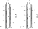
- Figure 2 is a cross-sectional side view of a portion of a catheter shaft 206 configured in accordance with another embodiment of the present technology.
- the shaft 206 can be generally similar to the shaft 106 shown in Figures 1A-1B , except the coil 170 in the shaft 206 of Figure 2 surrounds the outer braid 162 within the overlapping region 180.
- Figures 3-8 are cross-sectional side views of distal portions of catheter shafts configured in accordance with the present technology. Any of the distal portions (or aspects thereof) described below can be combined with any of the catheter shafts described above with reference to Figures 1A-2 . As described in greater detail below, the distal portion embodiments of the present technology include regions of varying stiffness and/or preferential bending that provide improved bending/buckling at the distal portion when contacting the wall of tortuous vessels, thereby improving ease of navigation of the corresponding shaft and/or distal portion.
- Figure 3 is a cross-sectional side view of a distal portion 300 of a catheter shaft configured in accordance with the present technology.
- the distal portion 300 can include a radiopaque marker 317, an inner polymer structure 314, an outer polymer structure 316 surrounding at least a portion of the inner polymer structure 314, and a coil 370 wrapped around at least a portion of the inner polymer structure 314.
- the inner polymer structure 314 extends the length of the distal portion 300 such that the inner polymer structure 314 terminates distally at an opening 318 at the distal terminus of the distal portion 300.
- the inner polymer structure 314 defines a lumen that can be generally continuous with the lumen 103 of any of the shaft embodiments described above with reference to Figures 1A-2 .
- the inner polymer structure 314 can include a single layer of material or it can have two or more layers of the same or different materials.
- the inner polymer structure 314 includes a first layer 312 and a second layer 313 surrounding the first layer 312. Accordingly, an inner surface of the first layer 312 defines the shaft lumen 103 at the distal portion 300.
- the first layer 312 can comprise a lubricious polymer such as HDPE or PTFE, for example, or platinum, PEEK, PE, PP, or a copolymer of tetrafluoroethylene, such as FEP, a copolymer of tetrafluoroethylene with perfluoroethers, such as PFA (more specifically, perfluoropropyl vinyl ether or perfluoromethyl vinyl ether), or the like.
- the second layer 313 can be made of any of the materials described above with respect to the inner polymer structure 114.
- the inner polymer structure 314 can be formed of a single layer (e.g., only the first layer 312, only the second layer 313, etc.), and in other embodiments the inner polymer structure 314 can include more than two layers (e.g., three layers, four layers) depending on the desired characteristics of the distal portion 300 of the catheter.
- the stiffness of the inner polymer structure 314 can be generally uniform along its length, or the stiffness can vary along its length.
- the second layer 313 of the inner polymer structure 314 includes two unique portions along its length (labeled proximal to distal as first portion 319 and second portion 320).
- the first and second portions 319, 320 can have at least one of a different size, shape, thickness, and material composition such that the first portion 319 has a different stiffness than the second portion 320 (or in other words, the second portion 320 is softer than the first portion 319).
- the first portion 319 can be a first material and the second portion 320 can be a second material different than the first material such that a stiffness of the first portion 319 is greater than a stiffness of the second portion 320.
- a stiffness of the inner polymer structure 314 can increase in a proximal to distal direction along its length, or increase and decrease in a proximal to distal direction along its length.
- the second portion 320 can have a stiffness that is greater than or equal to the stiffness of the first portion 319.
- the inner polymer structure 314 can have more or fewer portions (e.g., one continuous portion, three portions, four portions, etc.).
- both the first and second layers 312, 313 of the inner polymer structure 314 extend along the entire length of the distal portion 300 such that the distal termini of both the first and second layers 312, 313 are at the distal terminus of the distal portion 300.
- the second portion 319 of the second layer 313 defines a portion of the distal terminus of the distal portion 300 of the shaft.
- the distal-most surfaces of both the inner and the outer polymer structures 314, 316 define the distal terminus of the distal portion 300 of the shaft.
- the first layer 312 terminates proximal to the distal terminus of the distal portion 300.
- the inner polymer structure 314 is shown having two portions 319, 320 in Figure 3 , in other embodiments the inner polymer structure 314 can have a single continuous portion or more than two portions (e.g., three portions, four portions, etc.). Moreover, although the second layer 313 is shown having multiple portions, in other embodiments the first layer 312 can additionally or alternatively include multiple portions.
- the outer polymer structure 316 directly contacts at least a portion of the inner polymer structure 314 and encases at least a portion of the coil 370.
- at least a portion of the surface of the coil 370 directly contacts the first and second portions 319, 320 of the second layer 313 of the inner polymer structure 314, while a remaining portion of the coil's surface directly contacts the outer polymer structure 316.
- the outer polymer structure 316 extends along the length of the distal portion 300 such that a distal terminus of the outer polymer structure 316 corresponds to the distal terminus of the distal portion 300.
- the outer polymer structure 316 extends along only a portion of the length of the distal portion 300 and/or has a proximal and/or distal terminus that does not correspond to a proximal terminus and/or distal terminus, respectively, of the distal portion 300.
- the outer polymer structure 316 (and/or portions thereof) can be made of any of the materials described above with respect to the outer polymer structure 116.
- the coil 370 can be one or more round wires or flat ribbons helically wound around the inner polymer structure 314, and the outer polymer structure 316 can encase at least a portion of the coil 370.
- the coil 370 can extend all or a portion of the length of the distal portion 300.
- the coil 370 has a distal terminus that is aligned with or just proximal of the radiopaque marker 317, and the radiopaque marker 317 is proximal of the distal terminus of the distal portion 300.
- a distal terminus of the coil 370 is spaced apart from a distal terminus of the shaft.
- the pitch of adjacent turns of the coil 370 may be tightly wound so that each turn touches the succeeding turn or the pitch may be set such that the coil 370 is wound in an open fashion.
- the pitch of the coil 370 can be the same or vary along the length of the coil 370.
- the coil 370 or portions thereof can be made of or include a radiopaque or imaging material.
- Figure 4 is a cross-sectional side view of a distal portion 400 of a catheter shaft configured in accordance with another embodiment of the present technology.
- the distal portion 400 can include a radiopaque marker 417, an inner polymer structure 414, an outer polymer structure 416 surrounding at least a portion of the inner polymer structure 414, and a coil 470 wound around at least a portion of the inner polymer structure 414.
- the inner polymer structure 414 defines a lumen that can be generally continuous with the lumen 103 of any of the shaft embodiments described above with reference to Figures 1A-2 .
- the inner polymer structure 414 can include a single layer of material or it can have two or more layers of the same or different materials.
- the inner polymer structure 414 includes a first layer 412 and a second layer 413 surrounding the first layer 412. Accordingly, an inner surface of the first layer 412 defines the shaft lumen 103 at the distal portion 400.
- the first layer 412 can comprise a lubricious polymer such as HDPE or PTFE, for example, or platinum, PEEK, PE, PP, or a copolymer of tetrafluoroethylene, such as FEP, a copolymer of tetrafluoroethylene with perfluoroethers, such as PFA (more specifically, perfluoropropyl vinyl ether or perfluoromethyl vinyl ether), or the like.
- the second layer 413 can be made of any of the materials described above with respect to the inner polymer structure 414.
- the inner polymer structure 414 can be formed of a single layer (e.g., only the first layer 412, only the second layer 413, etc.), and in other embodiments the inner polymer structure 414 can include more than two layers (e.g., three layers, four layers) depending upon the desired characteristics of the catheter.
- the stiffness of the inner polymer structure 414 can be generally uniform along its length, or the stiffness can vary along its length.
- the second layer 413 of the inner polymer structure 414 includes two unique portions (labeled proximal to distal as first portion 419 and second portion 420) adjacent one another along its length having different stiffnesses.
- the first and second portions 419, 420 can have at least one of a different size, shape, thickness, and material composition such that the first portion 419 has a different stiffness than the second portion 420.
- the first portion 419 can be a first material and the second portion 420 can be a second material different than the first material such that a stiffness of the first portion 419 is greater than a stiffness of the second portion 420.
- a stiffness of the inner polymer structure 414 can increase in a proximal to distal direction along its length, or increase and decrease in a proximal to distal direction along its length.
- the second portion 420 has a stiffness that is greater than or equal to the stiffness of the first portion 419.
- the second layer 413 of the inner polymer structure 414 extends along only a portion of the length of the distal portion 400 such that a distal terminus of the second layer 413 is proximal of the distal terminus of the outer polymer structure 416 and the distal terminus of the distal portion 400. Accordingly, in contrast to the embodiment shown in Figure 3 , only the distal-most portions of the outer polymer structure 416 and the first layer 312 define the distal terminus of the distal portion 400 of the shaft (and not the second layer 313).
- the inner polymer structure 414 is shown having two portions 419, 420 in Figure 4 , in other embodiments the inner polymer structure 414 can have a single continuous portion or more than two portions (e.g., three portions, four portions, etc.). Moreover, although the second layer 413 is shown having multiple portions, in other embodiments the first layer 412 can additionally or alternatively include multiple portions.
- the outer polymer structure 416 directly contacts at least a portion of the inner polymer structure 414 and encases at least a portion of the coil 470.
- at least a portion of the surface of the coil 470 directly contacts the inner polymer structure 414, while a remaining portion of the coil's surface directly contacts the outer polymer structure 416.
- the outer polymer structure 416 extends along the length of the distal portion 400 such that a distal terminus of the outer polymer structure 416 corresponds to the distal terminus of the distal portion 400.
- the outer polymer structure 416 (and/or portions thereof) can be made of any of the materials described above with respect to the outer polymer structure 116.
- Such a construction allows for improved bending and trackability at the distal tip bend (for positioning at the aneurysm neck) while the proximal stiffer region of the distal portion 300/400 provides additional support and stability to the distal portion 300/400, thereby lessening or preventing kickback of the shaft during deployment of an occlusive device (such as a coil) in an aneurysm.
- an occlusive device such as a coil
- the inner polymer structure 514 can be formed of a single layer (e.g., only the first layer 512, only the second layer 513, etc.), and in other embodiments the inner polymer structure 514 can include more than two layers (e.g., three layers, four layers) depending upon the desired characteristics of the device.
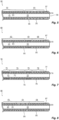
- the coil 570 has a first portion 572 and a second portion 574 distal of the first portion 572.
- the first portion 572 has a first pitch and the second portion 574 has a second pitch that is greater than the first pitch. Accordingly, a length of the distal portion 500 corresponding to the first portion 572 of the coil 570 is less flexible than a length of the distal portion 500 corresponding to the second portion 574 of the coil 570.
- the coil 570 or portions thereof can be made of or include a radiopaque or imaging material.
- Figure 6 is a cross-sectional side view of a distal portion 600 of a catheter shaft configured in accordance with the present technology.
- the distal portion 600 can include a radiopaque marker 617, an inner polymer structure 614, an outer polymer structure 616 surrounding at least a portion of the inner polymer structure 614, and a coil 670 wound around at least a portion of the inner polymer structure 614.
- the inner polymer structure 614 extends the length of the distal portion 600 such that the inner polymer structure 614 terminates distally at an opening 618 at the distal terminus of the distal portion 600.
- the inner polymer structure 614 defines a lumen that can be generally continuous with the lumen 103 of any of the shaft embodiments described above with reference to Figures 1A-2 .
- the inner polymer structure 614 can include a single layer of material or it can have two or more layers of the same or different materials.
- the inner polymer structure 614 can include a first layer 612 and a second layer 613 surrounding the first layer 612. As such, an inner surface of the first layer 612 defines the shaft lumen 103.
- the second layer 613 can be made of any of the materials described above with respect to the inner polymer structure 614.
- the first layer 612 can include a lubricious polymer such as HDPE or PTFE, for example, or a copolymer of tetrafluoroethylene with perfluoroalkyl vinyl ether (PFA) (more specifically, perfluoropropyl vinyl ether or perfluoromethyl vinyl ether), or the like.
- the inner polymer structure 614 can be formed of a single layer (e.g., only the first layer 612, only the second layer 613, etc.), and in other embodiments the inner polymer structure 614 can include more than two layers (e.g., three layers, four layers) depending upon the desired characteristics of the device.
- the outer polymer structure 616 directly contacts at least a portion of the inner polymer structure 614 and encases at least a portion of the coil 670.
- at least a portion of the surface of the coil 670 directly contacts the second layer 613 of the inner polymer structure 614, while a remaining portion of the coil's surface directly contacts the outer polymer structure 616.
- the outer polymer structure 616 extends along the length of the distal portion 600 such that a distal terminus of the outer polymer structure 616 corresponds to the distal terminus of the distal portion 600.
- the outer polymer structure 616 (and/or portions thereof) can be made of any of the materials described above with respect to the outer polymer structure 116.
- the coil 670 can be one or more round wires or flat ribbons helically wound around the inner polymer structure 614.
- the coil 670 can extend all or a portion of the length of the distal portion 600.
- the coil 670 has a distal terminus that is aligned with or just proximal of the radiopaque marker 617, and the radiopaque marker 617 is proximal of the distal terminus of the distal portion 600.
- the pitch of adjacent turns of the coil 670 may be tightly wound so that each turn touches the succeeding turn or the pitch may be set such that the coil 670 is wound in an open fashion.
- the pitch of the coil 670 can be the same or vary along the length of the coil 670.
- the coil 670 has a first portion 672, a second portion 674 distal of the first portion 672, and a third portion 676 distal of the second portion 674.
- the first portion 672 has a first pitch
- the second portion 674 has a second pitch less than the first pitch
- the third portion 676 has a third pitch greater than the second pitch. Accordingly, regions of the distal portion 600 corresponding to the first and third portions 672, 676 of the coil 670 are more flexible than a region of the distal portion 600 corresponding to the second portion 674 of the coil 670.
- the first and third pitches can be the same or different so long as the average pitch of the first and third portions 672, 676 is less than the average pitch of the second portion 674.
- the coil 670 or portions thereof can be made of or include a radiopaque or imaging material.
- Figure 7 is a cross-sectional side view of a distal portion 700 of a catheter shaft configured in accordance with the present technology.
- the distal portion 700 can include a radiopaque marker 717, an inner polymer structure 714, an outer polymer structure 716 surrounding at least a portion of the inner polymer structure 714, and a coil 770 wound around at least a portion of the inner polymer structure 714.
- the inner polymer structure 714 extends the length of the distal portion 700 such that the inner polymer structure 714 terminates distally at an opening 718 at the distal terminus of the distal portion 700.
- the inner polymer structure 714 defines a lumen that can be generally continuous with the lumen 103 of any of the shaft embodiments described above with reference to Figures 1A-2 .
- the first layer 712 can comprise a lubricious polymer such as HDPE or PTFE, for example, or platinum, PEEK, PE, PP, or a copolymer of tetrafluoroethylene, such as FEP, a copolymer of tetrafluoroethylene with perfluoroethers, such as PFA (more specifically, perfluoropropyl vinyl ether or perfluoromethyl vinyl ether), or the like.
- a lubricious polymer such as HDPE or PTFE, for example, or platinum, PEEK, PE, PP, or a copolymer of tetrafluoroethylene, such as FEP, a copolymer of tetrafluoroethylene with perfluoroethers, such as PFA (more specifically, perfluoropropyl vinyl ether or perfluoromethyl vinyl ether), or the like.
- the inner polymer structure 714 can be formed of a single layer (e.g., only the first layer 712, only the second layer 713, etc.), and in other embodiments the inner polymer structure 714 can include more than two layers (e.g., three layers, four layers) depending upon the desired characteristics of the device.
- the outer polymer structure 716 directly contacts at least a portion of the inner polymer structure 714 and encases at least a portion of the coil 770.
- at least a portion of the surface of the coil 770 directly contacts the second layer 713 of the inner polymer structure 714, while a remaining portion of the coil's surface directly contacts the outer polymer structure 716.
- the outer polymer structure 716 extends along the length of the distal portion 700 such that a distal terminus of the outer polymer structure 716 corresponds to the distal terminus of the distal portion 700.
- the outer polymer structure 716 (and/or portions thereof) can be made of any of the materials described above with respect to the outer polymer structure 116.
- the coil 770 can be one or more round wires or flat ribbons helically wound around the inner polymer structure 714.
- the coil 770 can extend all or a portion of the length of the distal portion 700.
- the coil 770 has a distal terminus that is aligned with or just proximal of the radiopaque marker 717, and the radiopaque marker 717 is proximal of the distal terminus of the distal portion 700.
- the pitch of adjacent turns of the coil 770 may be tightly wound so that each turn touches the succeeding turn or the pitch may be set such that the coil 770 is wound in an open fashion.
- the pitch of the coil 770 can be the same or vary along the length of the coil 770.
- the coil 770 has a first portion 772, a second portion 774 distal of the first portion 772, a third portion 776 distal of the second portion 774, and a fourth portion 778 distal of the third portion 776.
- the first portion 772 has a first pitch
- the second portion 774 has a second pitch greater than the first pitch
- the third portion 776 has a third pitch less than the second pitch
- the fourth portion 778 has a fourth pitch greater than each of the first and third pitches. Accordingly, regions of the distal portion 700 corresponding to the first and third portions 772, 776 of the coil 770 are less flexible than regions of the distal portion 700 corresponding to the second and fourth portions 774, 778 of the coil 770.
- the first and third pitches can be generally the same, and the second and fourth pitches can be generally the same and greater than the first and third pitches.
- the first and third portions 772, 776 can have the same and/or different pitches and/or the second and fourth portions 774, 778 can have the same and/or different pitches, so long as the average pitch of the first and third portions 772, 776 is less than the average pitch of the second and fourth portions 774, 778.
- the coil 770 or portions thereof can be made of or include a radiopaque or imaging material.
- the inner polymer structure 814 can include two or more layers.
- the inner polymer structure 814 can include a first layer 812 and a second layer 813 surrounding the first layer 812.
- an inner surface of the first layer 812 defines the shaft lumen 103.
- the second layer 813 can be made of any of the materials described above with respect to the inner polymer structure 814.
- the outer polymer structure 816 directly contacts at least a portion of the inner polymer structure 814 and encases at least a portion of the coil 870.
- at least a portion of the surface of the coil 870 directly contacts the second layer 813 of the inner polymer structure 814, while a remaining portion of the coil's surface directly contacts the outer polymer structure 816.
- the outer polymer structure 816 extends along the length of the distal portion 800 such that a distal terminus of the outer polymer structure 816 corresponds to the distal terminus of the distal portion 800.
- the outer polymer structure 816 (and/or portions thereof) can be made of any of the materials described above with respect to the outer polymer structure 116.
- the coil 870 has a first portion 872, a second portion 874 distal of the first portion 872, and a third portion 876 distal of the second portion 874.
- the first portion 872 has a first pitch
- the second portion 874 has a second pitch greater than the first pitch
- the third portion 876 has a third pitch less than the second pitch. Accordingly, regions of the distal portion 800 corresponding to the first and third portions 872, 876 of the coil 870 are less flexible than a region of the distal portion 800 corresponding to the second portion 874 of the coil 870.
- the first and third pitches can be the same or different so long as the average pitch of the first and third portions 872, 876 is less than the average pitch of the second portion 874.
- the coil 870 or portions thereof can be made of or include a radiopaque or imaging material.
Description
- The present technology relates generally to catheters. More specifically, the invention relates to catheter shaft construction.
- A wide variety of medical devices have been developed for intravascular use. Catheters, for example, are commonly used to facilitate navigation through and/or treatment within the anatomy of a patient. To direct the distal portion of the catheter to the correct location in the vasculature, a physician must apply longitudinal forces, and sometimes rotational forces (i.e., torsional forces), from the proximal end of the catheter. For the catheter shaft to transmit these forces from the proximal end to the distal end, the catheter must be sufficiently rigid to be pushed through the blood vessel (a property commonly referred to as "pushability"), yet flexible enough to navigate through the often tortuous bends in the blood vessel. The catheter may also require sufficient torsional stiffness to transmit the applied torque (a property commonly referred to as "torqueability"). A need exists for catheter shafts that accomplish a balance between longitudinal rigidity, torsional stiffness, and flexibility.
-
U.S. Patent Application Publication No. 2011/0238041 A1 by Lim et al. describes a multi-layered catheter having various sections of different flexibility extending distally along the length of the catheter. European Patent Application PublicationEP 2 174 685 A1 by Asahi Intecc Co Ltd. describes a catheter that includes a hollow coil whose outer and inner surfaces are coated with outer and inner resin layers. The catheter also includes a tapered tip and a braid embedded in the catheter body and the tip. International Publication No.WO 03/086519 A1 by Biosphere Medical U.S. Patent Application Publication No. 006/089618 A1 by McFerran et al. describes a catheter having a preshaped tip configuration. The catheter may include features that transition the stiffness and flexibility of the catheter. European Patent Application PublicationEP 0 661 072 A1 by Terumo Corp. describes a catheter that includes an intermediate layer including a double layer coil portion and a rigid layer. - Many aspects of the present technology can be better understood with reference to the following drawings. The components in the drawings are not necessarily to scale. Instead, emphasis is placed on illustrating clearly the principles of the present disclosure.
-
Figure 1A is a side view of a catheter in accordance with the present technology. -
Figure 1B is a cross-sectional side view of a portion the catheter shaft shown inFigure 1A . -
Figure 2 is a cross-sectional side view of a portion of an elongated catheter shaft configured in accordance with another embodiment of the present technology. -
Figure 3 is a cross-sectional side view of a distal portion of an elongated catheter shaft configured in accordance with the present technology. -
Figure 4 is a cross-sectional side view of a distal portion of an elongated catheter shaft configured in accordance with the present technology. -
Figure 5 is a cross-sectional side view of a distal portion of an elongated catheter shaft configured in accordance with the present technology. -
Figure 6 is a cross-sectional side view of a distal portion of an elongated shaft configured in accordance with the present technology. -
Figure 7 is a cross-sectional side view of a distal portion of an elongated shaft configured in accordance with the present technology. -
Figure 8 is a cross-sectional side view of a distal portion of an elongated shaft configured in accordance with the present technology. - The present invention is directed to catheters as defined in the claims. Specific details of several embodiments of catheter devices, systems, and methods in accordance with the present technology are described below with reference to
Figures 1A-8 . With regard to the terms "distal" and "proximal" within this description, unless otherwise specified, the terms can reference a relative position of the portions of a catheter and/or an associated device with reference to an operator and/or a location in the vasculature. Also, the term "thickness" as used herein with respect to a particular material or layer refers to the perpendicular distance between the plane running through and generally parallel with the radially outermost surface of the particular material or layer and the plane running through and generally parallel with the radially innermost surface of the particular material or layer. - The methods herein do not form part of the claimed invention.
-
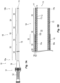
Figure 1A is a side view of acatheter 100 configured in accordance with an embodiment of the present technology, andFigure 1B is a cross-sectional side view of a portion of thecatheter 100 shown inFigure 1A . Referring toFigures 1A-1B together, thecatheter 100 includes ahandle assembly 101 and anelongated shaft 106 having aproximal portion 106a coupled to thehandle assembly 101 and adistal portion 106b. Thehandle assembly 101 includes ahub 102 configured to facilitate connection to other devices (e.g., a syringe, a Y-adapter, etc.) and atransition portion 104 configured to provide strain relief at theproximal portion 106a. In other embodiments, thehandle assembly 101 can have other suitable configurations based on the desired functions and characteristics of thecatheter 100. - The
shaft 106 is a generally tubular member having an inner surface that defines a lumen 103 (Figure 1B ) extending from theproximal portion 106a of theshaft 106 to anopening 118 at the distal terminus of thedistal portion 106b. In some embodiments, theshaft 106 can include a radiopaque marker 117 (Figure 1B ) surrounding thelumen 103 at or just proximal to theopening 118. Thelumen 103 is configured to slidably receive and facilitate the passage therethrough of one or more medical devices, such as guidewires, balloon catheters, implants, intrasaccular occlusion devices (e.g., coils, expandable cages, expandable meshes, etc.), infusion devices, stents and/or stent-grafts, intravascular occlusion devices, clot retrievers, implantable heart valves, and other suitable medical devices and/or associated delivery systems. Additionally, thelumen 103 is configured to receive one or more fluids therethrough, such as radiopaque dye, saline, drugs, and the like. - The size of the
lumen 103 can vary, depending on the desired characteristics of thecatheter 100. For example, in some embodiments theshaft 106 can have an inner diameter (e.g., lumen diameter) between about 0.254 millimeters (about 0.01 inches) and about 1.27 millimeters (about 0.05 inches) (e.g., 0.4318 millimeters (0.017 inches), 1.1303 millimeters (0.0445 inches, etc.), and in some embodiments between about 0.508 millimeters (about 0.02 inches) and 1.143 millimeters (about 0.045 inches) (e.g., 0.5334 millimeters (0.021 inches), etc.). In a particular embodiment, the inner diameter is between about 0.635 millimeters (about 0.025 inches) and about 1.016 millimeters (about 0.04 inches) (e.g., 0.6858 millimeters (0.027 inches, 0.8128 millimeters (0.032 inches, etc.). Although theshaft 106 shown inFigure 1A has a generally round cross-sectional shape, it will be appreciated that theshaft 106 can include other cross-sectional shapes or combinations of shapes. For example, the cross-sectional shape of theshaft 106 can be oval, rectangular, square, triangular, polygonal, and/or any other suitable shape and/or combination of shapes. - The outer diameter of the
shaft 106 can be the same or vary along its length. For example, in the embodiment shown inFigures 1A-1B , theshaft 106 has afirst portion 190 with a first diameter, atapered portion 192 with a diameter that decreases in a proximal to distal direction, and asecond portion 194 with a second diameter less than the first diameter. The length of thetapered portion 192 can be between about 1 cm and about 5 cm. In some embodiments, theshaft 106 does not include asecond portion 194 and thetapered portion 192 extends distally to the distal terminus of theshaft 106. In other embodiments, theshaft 106 has an outer diameter that is generally constant along its length. Moreover, the length and/or outside diameter of theshaft 106 is generally selected for the desired use of thecatheter 100. For example, in those embodiments where thecatheter 100 is configured as a guide catheter for enabling intravascular insertion and navigation, the outside diameter of theshaft 106 can be between about 1 millimeters (about 3 Fr) and about 3.333 millimeters (about 10 Fr). In those embodiments where thecatheter 100 is configured as a microcatheter for use within small anatomies of the patient, the outside diameter of theshaft 106 can be between about 0.333 millimeters (about 1 Fr) and about 1 millimeters (about 3 Fr). - Many embodiments of the present technology are particularly useful in treating targets located in tortuous and narrow vessels, such as certain sites in the neurovascular system, the coronary vascular system, or the peripheral vascular system (e.g., the superficial femoral, popliteal, or renal arteries). Neurovascular target sites, such as sites in the brain, are often accessible only via a tortuous vascular path. Although some embodiments of the
catheter 100 are described in terms of intravascular use, in other embodiments thecatheter 100 may be suited for uses in the digestive system, soft tissues, and/or any other insertion into an organism for medical uses. For example, in some embodiments, thecatheter 100 may be significantly shorter and used as an introducer sheath, while in other embodiments thecatheter 100 may be adapted for other medical procedures. - In the embodiment shown in
Figure 1B , theelongated shaft 106 includes aninner polymer structure 114 and anouter polymer structure 116 surrounding at least a portion of theinner polymer structure 114. Theshaft 106 shown inFigure 1B also has aninner braid 160 embedded in theouter polymer structure 116, anouter braid 162 surrounding at least a portion of theinner braid 160, and acoil 170 wrapped around at least a portion of theinner polymer structure 114. Each of these subcomponents will now be described in greater detail. - Referring again to
Figures 1A-1B together, theinner polymer structure 114 extends from theproximal portion 106a of theshaft 106 to a location within thedistal portion 106b of theshaft 106. For example, in the embodiment shown inFigure 1B , theinner polymer structure 114 extends from theproximal portion 106a of theshaft 106 to theopening 118 at the distal terminus of thedistal portion 106b (e.g., the entire length of theshaft 106 or substantially the entire length of the shaft 106). In other embodiments, theinner polymer structure 114 extends along only a portion of the length of theshaft 106 and/or has a proximal and/or a distal terminus that does not correspond to a proximal terminus and/or a distal terminus, respectively, of theshaft 106. The length of theinner polymer structure 114 can vary depending upon, for example, the length of theshaft 106 and the desired characteristics and functions of thecatheter 100. - The
inner polymer structure 114 can be made of any suitable polymer (and/or combination of multiples polymers) and by any suitable process. Suitable polymers can include, for example, polyoxymethylene (POM), polybutylene terephthalate (PBT), polyether block ester, polyether block amide (PEBA), fluorinated ethylene propylene (FEP), polyethylene (PE), polypropylene (PP), polyvinylchloride (PVC), polyurethane, polytetrafluoroethylene (PTFE), polyether-ether ketone (PEEK), polyimide, polyamide, polyphenylene sulfide (PPS), polyphenylene oxide (PPO), polysulfone, nylon, perfluoro(propyl vinyl ether) (PFA), polyether-ester, platinum, polymer/metal composites, etc., or mixtures, blends or combinations thereof, and may also include or be made up of a lubricious polymer having a low coefficient of friction. In some embodiments (not shown), theinner polymer structure 114 includes one or more metals or metal alloys and/or combinations thereof. In a particular embodiment, theinner polymer structure 114 does not include any polymer material and solely comprises a metal and/or metal alloy. - The
inner polymer structure 114 can include a single layer of material or it can have two or more layers of the same or different materials. For example, in the embodiment shown inFigure 1B , theinner polymer structure 114 includes afirst layer 112 and asecond layer 113 surrounding at least a portion of thefirst layer 112. An inner surface of thefirst layer 112 defines theshaft lumen 103. Thefirst layer 112 can comprise a lubricious polymer such as HDPE or PTFE, for example, or platinum, PEEK, PE, PP, or a copolymer of tetrafluoroethylene, such as FEP, a copolymer of tetrafluoroethylene with perfluoroethers, such as perfluoroalkoxy alkanes (PFA) (more specifically, perfluoropropyl vinyl ether or perfluoromethyl vinyl ether), or the like. Thesecond layer 113 can be made of any of the materials described above with respect to theinner polymer structure 114 such as, for example, PEBA, PVC, PE, etc. In other embodiments, theinner polymer structure 114 can be formed of a single layer (e.g., only thefirst layer 112, only thesecond layer 113, etc.), and in other embodiments theinner polymer structure 114 can include more than two layers (e.g., three layers, four layers, etc.) depending upon the desired characteristics of thecatheter 100. In some embodiments the first andsecond layers shaft 106, and in other embodiments the first andsecond layers shaft 106. For example, in a particular embodiment, thesecond layer 113 extends along only a portion of the length of theshaft 106 while thefirst layer 112 extends the entire length (or substantially the entire length) of theshaft 106. In any of the above embodiments, thefirst layer 112 can have a thickness of about 0.0127 millimeters (about 0.0005 inches) to about 0.127 millimeters (about 0.005 inches), or about 0.0254 millimeters (about 0.001 inches) to about 0.0762 millimeters (about 0.003 inches). Also, in any of the above embodiments, thesecond layer 113 can have a thickness of about 0.0127 millimeters (about 0.0005 inches) to about 0.127 millimeters (about 0.005 inches), or about 0.0254 millimeters (about 0.001 inches) to about 0.0762 millimeters (about 0.003 inches). - The stiffness of the
inner polymer structure 114 can be generally uniform along its length, or the stiffness can vary along its length. The stiffness variation is a function of the size, shape, thickness, and/or materials of theinner polymer structure 114. In embodiments where the stiffness of theinner polymer structure 114 varies along its length, the stiffness can change continuously (e.g., gradually) and/or be stepped from one section to another. In some embodiments, the stiffness of theinner polymer structure 114 decreases in a proximal to distal direction along its length. In other embodiments, the stiffness of theinner polymer structure 114 increases in a proximal to distal direction along it length, and/or increases and decreases in a proximal to distal direction along its length. Additionally, theinner polymer structure 114 can be made of or include a radiopaque material for radiographic visualization. Exemplary radiopaque materials include, for example, gold, platinum, palladium, tantalum, tungsten alloy, polymer materials loaded with radiopaque fillers, and the like. Likewise, in some embodiments, theinner polymer structure 114 is made of or include a material that may aid in MRI imaging, such as, for example, tungsten, Elgiloy, MP35N, nitinol, and others. - In the embodiment shown in
Figures 1A-1B , theouter polymer structure 116 directly contacts at least a portion of theinner polymer structure 114 and encases at least a portion of each of theinner braid 160, theouter braid 162, and thecoil 170. Theouter polymer structure 116 extends distally from theproximal portion 106a of theshaft 106 to a location within thedistal portion 106b of the shaft 106 (e.g., the entire length of theshaft 106 or substantially the entire length of the shaft 106). The length of theouter polymer structure 116 can vary depending upon, for example, the length of theshaft 106 and the desired characteristics and functions of thecatheter 100. In some embodiments, theouter polymer structure 116 extends substantially the entire length of theshaft 106. In other embodiments, theouter polymer structure 116 extends along only a portion of the length of theshaft 106 and/or has a proximal and/or distal terminus that does not correspond to a proximal terminus and/or distal terminus, respectively, of theshaft 106. - The outer polymer structure 116 (and/or portions thereof) can be made of any suitable polymer (or composites or combinations thereof) and by any suitable process. Suitable polymers can include, for example, polyoxymethylene (POM), polybutylene terephthalate (PBT), polyether block ester, polyether block amide (PEBA), fluorinated ethylene propylene (FEP), polyethylene (PE), polypropylene (PP), polyvinylchloride (PVC), polyurethane, polytetrafluoroethylene (PTFE), polyether-ether ketone (PEEK), polyimide, polyamide, polyphenylene sulfide (PPS), polyphenylene oxide (PPO), polysulfone, nylon, perfluoro(propyl vinyl ether) (PFA), polyether-ester, platinum, polymer/metal composites, etc., or mixtures, blends or combinations thereof. In several embodiments, the
outer polymer structure 116 is or at least includes a lubricious polymer. In some embodiments (not shown), theouter polymer structure 116 includes one or more metals or metal alloys (combinations thereof). In a particular embodiment, theouter polymer structure 116 does not include any polymer material and solely comprises a metal and/or metal alloy. - In some embodiments, the stiffness of the
outer polymer structure 116 varies along its length. In such embodiments, the stiffness variation may be continuous or stepped by varying the size, shape, thickness, and/or material composition of theouter polymer structure 116. For example, in the embodiment shown inFigures 1A-1B , theouter polymer structure 116 includes four unique portions along its length (labeled proximal to distal as first, second, third andfourth portions portions first portion 120 has a first stiffness, thesecond portion 130 has a second stiffness less than the first stiffness, thethird portion 140 has a third stiffness less than the second stiffness, and thefourth portion 150 has a fourth stiffness less than the third stiffness. In other embodiments, the stiffness of theouter polymer structure 116 and/or the stiffnesses of theindividual portions second portion 130 can be stiffer than thefirst portion 120, etc.), increase and decrease in a proximal to distal direction (e.g., thesecond portion 130 can be stiffer than thefirst portion 120 but less stiff than thethird portion 140, etc.), or be generally uniform in a proximal to distal direction. In other embodiments, theouter polymer structure 116 can have more or fewer portions (e.g., one continuous portion, two portions, three portions, five portions, etc.). - In some embodiments, one or both of the first and
second portions fourth portion 150 can have a thickness of about 0.0254 millimeters (about 0.001 inches) to about 0.0762 millimeters (about 0.003 inches). The proximal portion of the taperedportion 192 can have a thickness equivalent to that of the correspondingsecond portion 130, and the distal portion of the taperedportion 192 can have a thickness generally equivalent to that of the correspondingfourth portion 150. Thus, thethird portion 140 can have a proximal thickness between about 0.0762 millimeters (about 0.003 inches) to about 0.127 millimeters (about 0.005 inches), or in some embodiments about 0.1016 millimeters (about 0.004 inches) to about 0.254 millimeters (about 0.010 inches), and a distal portion have a thickness of about 0.0254 millimeters (about 0.001 inches) to about 0.0762 millimeters (about 0.003 inches). - The
portions outer polymer structure 116 can include two or more layers (e.g., an inner layer surrounding an outer layer, etc.), and each layer can have the same or different material compositions, thicknesses, and/or stiffnesses. Additionally, theportions portions Figure 1B , each of theportions fourth portions fourth portions third portion 140, however, includes the tapered portion 192 (Figure 1A ) and thus varies in thickness (and stiffness) along its length. In other embodiments, thethird portion 140 does not coincide with the taperedportion 192 and/or the taperedportion 192 spans more than one of theportions - It will be appreciated that while the
inner polymer structure 114 and theouter polymer structure 116 are described herein as separate components with respect to the illustrated embodiments, the inner andouter polymer structures inner polymer structure 114 andouter polymer structure 116 may be provided separately, but attached or combined together to physically form a single layer (e.g., a single homogeneous material). - Referring still to the embodiment shown in
Figure 1B , theinner braid 160 is on and around theinner polymer structure 114, and theouter polymer structure 116 is on and around theinner braid 160. In some embodiments, theinner braid 160 directly contacts at least a portion of both theinner polymer structure 114 and theouter polymer structure 116. In other embodiments, theouter polymer structure 116 is between at least a portion of theinner polymer structure 114 and at least a portion of theinner braid 160. In the embodiment shown inFigures 1A-1B , theinner braid 160 extends distally from theproximal portion 106a of theshaft 106 to adistal terminus 160b aligned with or just proximal of the distal terminus of theshaft 106. In other embodiments, theinner braid 160 extends the entire length of theshaft 106. The length of theinner braid 160 can vary depending upon, for example, the length of theshaft 106 and the desired characteristics and functions of thecatheter 100. - In some embodiments, at least a portion of the
inner braid 160 is coextensive with at least a portion of theouter braid 162. For example, in the embodiment shown inFigure 1B , theinner braid 160 has adistal terminus 160b located at a position along theshaft 106 distal of a proximal terminus (not shown) of theouter braid 162 and proximal of adistal terminus 162b of theouter braid 162. In other embodiments (not shown), no portion of theinner braid 160 is coextensive with a portion of theouter braid 162. Additionally, in some embodiments at least a portion of theinner braid 160 is coextensive with at least a portion of thecoil 170, and in other embodiments theinner braid 160 is adjacent to and/or spaced apart from thecoil 170 along the length of theshaft 106. For example, in the embodiment shown inFigure 1B , thedistal terminus 160b of theinner braid 160 is located at a position along theshaft 106 proximal of aproximal terminus 170a of thecoil 170 such that no portion of theinner braid 160 is coextensive with any portion of thecoil 170. Alternatively, in some embodiments (not shown) thedistal terminus 160b of theinner braid 160 is located at a position along theshaft 106 distal of aproximal terminus 170a of thecoil 170 such that at least a portion of theinner braid 160 is coextensive with at least a portion of thecoil 170. - In the embodiment shown in
Figures 1A-1B , theouter braid 162 is around theinner braid 160, and theouter polymer structure 116 contacts theouter braid 162. In some embodiments theouter braid 162 directly contacts theinner braid 160. In other embodiments, theouter polymer structure 116 is between at least a portion of theinner braid 160 and at least a portion of theouter braid 162. In the embodiment shown inFigure 1B , a distal portion of theouter braid 162 is around a proximal portion of thecoil 170. In some embodiments theouter braid 162 directly contacts thecoil 170. In other embodiments, theouter polymer structure 116 is between at least a portion of theouter braid 162 and at least a portion of thecoil 170. - The
outer braid 162 extends distally from theproximal portion 106a of theshaft 106 to adistal terminus 162b proximal to the distal terminus of theshaft 106. In other embodiments, theouter braid 162 extends the entire length of theshaft 106. The length of theouter braid 162 can vary depending upon, for example, the length of theshaft 106 and the desired characteristics and functions of thecatheter 100. In some embodiments, at least a portion of theouter braid 162 is coextensive with at least a portion of thecoil 170. For example, in the embodiment shown inFigure 1B , thedistal terminus 162b of theouter braid 162 is located at a position along theshaft 106 that is distal of theproximal terminus 170a of thecoil 170. In those embodiments where at least a portion of theouter braid 162 is coextensive with at least a portion of thecoil 170, the coextensive portions of theouter braid 162 and thecoil 170 form anoverlapping region 180. As shown inFigure 1B , in some embodiments theouter braid 162 surrounds thecoil 170 within the overlappingregion 180. In other embodiments, thecoil 170 surrounds theouter braid 162 within the overlapping region 180 (Figure 2 , described in greater detail below). In yet other embodiments, theouter braid 162 is spaced apart from and/or adjacent to thecoil 170 such that no portion of theouter braid 162 is coextensive with any portion of thecoil 170. - The
inner braid 160 and/or theouter braid 162 can individually have a generally uniform pitch along its respective length or may have a varying pitch along its respective length. The flexibility of the individualinner braid 160 and/or theouter braid 162 may vary continuously along its respective length by continuously varying the pitch or may vary along its respective length in a stepwise fashion by stepwise varying the pitch. Moreover, theinner braid 160 and/or theouter braid 162 can individually have a generally constant braid angle along its respective length or have a varying braid angle along its respective length to provide different zones of stiffness and/or flexibility. Theinner braid 160 and/or theouter braid 162 can be formed of braided filaments having the same or varying diameters (individually and/or relative to the other braid). In some embodiments, theinner braid 160 and/or theouter braid 162 are further shaped using a heat setting process. Additionally, theinner braid 160 and theouter braid 162 can have the same or different pitch, stiffness, braid angle, filament diameters, and filament count. In some embodiments, the inner and/orouter braids shaft 106 includes a single braid. Additionally, in some embodiments, theinner braid 160 and/or theouter braid 162 can be made of or include a radiopaque or imaging material. - The inner 160 and/or
outer braids 162 are formed of a plurality of interwoven wires. The wires can have a circular or rectangular cross-sectional shape. The wires can be made of one or more metals, such as stainless steel, platinum, silver, tantalum, and the like. In some embodiments, the wires can include or be made of non-metallic materials. In some embodiments, the wires are made of a superelastic or shape-memory material, such as nitinol. For those embodiments utilizing wires having a rectangular shape, the wires can have a cross-sectional area of about 0.0127 millimeters (about 0.0005 inches) by 0.0635 millimeters (0.0025 inches) to about 0.0254 millimeters (about 0.001 inches) by 0.127 millimeters (0.005 inches). - The
coil 170 can be one or more round wires or flat ribbons helically wound around theinner polymer structure 114. In the embodiment shown inFigures 1A-1B , theouter polymer structure 116 encases thecoil 170. Theproximal terminus 170a of thecoil 170 is positioned along thedistal portion 106b of theshaft 106, and thedistal terminus 170b of thecoil 170 is positioned generally in alignment with or just proximal to the distal terminus of theshaft 106. Accordingly, thecoil 170 is completely disposed within the distal portion of the shaft. In other embodiments, at least a portion of thecoil 170 is outside of thedistal portion 106b of theshaft 106. The pitch of adjacent turns of thecoil 170 may be tightly wound so that each turn touches the succeeding turn or the pitch may be set such that thecoil 170 is wound in an open fashion. The pitch of thecoil 170 can be the same or may vary along the length of thecoil 170. Thecoil 170 can have a pitch of about 0.1016 millimeters (about 0.004 inches) to about 0.3556 millimeters (about 0.014 inches). In some embodiments, the pitch of thecoil 170 depends on the inner diameter of theshaft 106. For example, for a shaft inner diameter of about 0.4318 millimeters (about 0.017 inches), thecoil 170 can have a pitch of about 0.1016 millimeters (about 0.004 inches) to about 0.2286 millimeters (about 0.009 inches). For a shaft inner diameter of about 0.5334 millimeters (about 0.021 inches), thecoil 170 can have a pitch of about 0.1524 millimeters (about 0.006 inches) to about 0.2794 millimeters (about 0.011 inches). For a shaft inner diameter of about 0.6858 millimeters (about 0.027 inches), thecoil 170 can have a pitch of about 0.1778 millimeters (about 0.007 inches) to about 0.3048 millimeters (about 0.012 inches). For a shaft inner diameter of about 0.1143 millimeters (about 0.0045 inches), thecoil 170 can have a pitch of about 0.254 millimeters (about 0.010 inches) to about 0.3556 millimeters (about 0.014 inches). Additionally, in some embodiments, thecoil 170 or portions thereof can be made of or include a radiopaque or imaging material. - The wire of the
coil 170 can be made of one or more metals, such as stainless steel, platinum, silver, tantalum, and the like. In other embodiments, the wire of thecoil 170 can include or be made of non-metallic materials. In a particular embodiment, the wires are made of a superelastic or shape-memory material, such as nitinol The wire can have an outer diameter of about 0.0254 millimeters (about 0.001 inches) to about 0.127 millimeters (about 0.005 inches), or in some embodiments about 0.0254 millimeters (about 0.001 inches) to about 0.0762 millimeters (about 0.003 inches). - It will be appreciated that the
inner braid 160,outer braid 162, andcoil 170 can have other suitable configurations and/or relative positions along the length of theshaft 106. For example, in some embodiments theinner braid 160 can be coextensive with at least a portion of thecoil 170, and in some embodiments theinner braid 160 can be generally coextensive with theouter braid 162. In a particular embodiment, at least a portion of theouter braid 162 is not coextensive with a portion of thecoil 170. -
Figure 2 is a cross-sectional side view of a portion of acatheter shaft 206 configured in accordance with another embodiment of the present technology. Theshaft 206 can be generally similar to theshaft 106 shown inFigures 1A-1B , except thecoil 170 in theshaft 206 ofFigure 2 surrounds theouter braid 162 within the overlappingregion 180. -
Figures 3-8 are cross-sectional side views of distal portions of catheter shafts configured in accordance with the present technology. Any of the distal portions (or aspects thereof) described below can be combined with any of the catheter shafts described above with reference toFigures 1A-2 . As described in greater detail below, the distal portion embodiments of the present technology include regions of varying stiffness and/or preferential bending that provide improved bending/buckling at the distal portion when contacting the wall of tortuous vessels, thereby improving ease of navigation of the corresponding shaft and/or distal portion. -
Figure 3 is a cross-sectional side view of adistal portion 300 of a catheter shaft configured in accordance with the present technology. Thedistal portion 300 can include aradiopaque marker 317, aninner polymer structure 314, anouter polymer structure 316 surrounding at least a portion of theinner polymer structure 314, and acoil 370 wrapped around at least a portion of theinner polymer structure 314. As shown inFigure 3 , theinner polymer structure 314 extends the length of thedistal portion 300 such that theinner polymer structure 314 terminates distally at anopening 318 at the distal terminus of thedistal portion 300. Theinner polymer structure 314 defines a lumen that can be generally continuous with thelumen 103 of any of the shaft embodiments described above with reference toFigures 1A-2 . - The
inner polymer structure 314 can include a single layer of material or it can have two or more layers of the same or different materials. For example, in the embodiment shown inFigure 3 , theinner polymer structure 314 includes afirst layer 312 and asecond layer 313 surrounding thefirst layer 312. Accordingly, an inner surface of thefirst layer 312 defines theshaft lumen 103 at thedistal portion 300. Thefirst layer 312 can comprise a lubricious polymer such as HDPE or PTFE, for example, or platinum, PEEK, PE, PP, or a copolymer of tetrafluoroethylene, such as FEP, a copolymer of tetrafluoroethylene with perfluoroethers, such as PFA (more specifically, perfluoropropyl vinyl ether or perfluoromethyl vinyl ether), or the like. Thesecond layer 313 can be made of any of the materials described above with respect to theinner polymer structure 114. Moreover, in some embodiments theinner polymer structure 314 can be formed of a single layer (e.g., only thefirst layer 312, only thesecond layer 313, etc.), and in other embodiments theinner polymer structure 314 can include more than two layers (e.g., three layers, four layers) depending on the desired characteristics of thedistal portion 300 of the catheter. - The stiffness of the
inner polymer structure 314 can be generally uniform along its length, or the stiffness can vary along its length. In the embodiment shown inFigure 3 , thesecond layer 313 of theinner polymer structure 314 includes two unique portions along its length (labeled proximal to distal asfirst portion 319 and second portion 320). The first andsecond portions first portion 319 has a different stiffness than the second portion 320 (or in other words, thesecond portion 320 is softer than the first portion 319). For example, thefirst portion 319 can be a first material and thesecond portion 320 can be a second material different than the first material such that a stiffness of thefirst portion 319 is greater than a stiffness of thesecond portion 320. In other embodiments, a stiffness of theinner polymer structure 314 can increase in a proximal to distal direction along its length, or increase and decrease in a proximal to distal direction along its length. For example, in a particular embodiment, thesecond portion 320 can have a stiffness that is greater than or equal to the stiffness of thefirst portion 319. In other embodiments, theinner polymer structure 314 can have more or fewer portions (e.g., one continuous portion, three portions, four portions, etc.). - In the embodiment shown in
Figure 3 , both the first andsecond layers inner polymer structure 314 extend along the entire length of thedistal portion 300 such that the distal termini of both the first andsecond layers distal portion 300. Additionally, thesecond portion 319 of thesecond layer 313 defines a portion of the distal terminus of thedistal portion 300 of the shaft. As such, the distal-most surfaces of both the inner and theouter polymer structures distal portion 300 of the shaft. In other embodiments, thefirst layer 312 terminates proximal to the distal terminus of thedistal portion 300. - Although the
inner polymer structure 314 is shown having twoportions Figure 3 , in other embodiments theinner polymer structure 314 can have a single continuous portion or more than two portions (e.g., three portions, four portions, etc.). Moreover, although thesecond layer 313 is shown having multiple portions, in other embodiments thefirst layer 312 can additionally or alternatively include multiple portions. - Referring still to the embodiment shown in
Figure 3 , theouter polymer structure 316 directly contacts at least a portion of theinner polymer structure 314 and encases at least a portion of thecoil 370. For example, in the embodiment shown inFigure 3 , at least a portion of the surface of thecoil 370 directly contacts the first andsecond portions second layer 313 of theinner polymer structure 314, while a remaining portion of the coil's surface directly contacts theouter polymer structure 316. Additionally, theouter polymer structure 316 extends along the length of thedistal portion 300 such that a distal terminus of theouter polymer structure 316 corresponds to the distal terminus of thedistal portion 300. In other embodiments, theouter polymer structure 316 extends along only a portion of the length of thedistal portion 300 and/or has a proximal and/or distal terminus that does not correspond to a proximal terminus and/or distal terminus, respectively, of thedistal portion 300. Moreover, the outer polymer structure 316 (and/or portions thereof) can be made of any of the materials described above with respect to theouter polymer structure 116. - The
coil 370 can be one or more round wires or flat ribbons helically wound around theinner polymer structure 314, and theouter polymer structure 316 can encase at least a portion of thecoil 370. Thecoil 370 can extend all or a portion of the length of thedistal portion 300. For example, in the embodiment shown inFigure 3 , thecoil 370 has a distal terminus that is aligned with or just proximal of theradiopaque marker 317, and theradiopaque marker 317 is proximal of the distal terminus of thedistal portion 300. As such, a distal terminus of thecoil 370 is spaced apart from a distal terminus of the shaft. The pitch of adjacent turns of thecoil 370 may be tightly wound so that each turn touches the succeeding turn or the pitch may be set such that thecoil 370 is wound in an open fashion. The pitch of thecoil 370 can be the same or vary along the length of thecoil 370. Additionally, in some embodiments, thecoil 370 or portions thereof can be made of or include a radiopaque or imaging material. -
Figure 4 is a cross-sectional side view of adistal portion 400 of a catheter shaft configured in accordance with another embodiment of the present technology. Thedistal portion 400 can include aradiopaque marker 417, aninner polymer structure 414, anouter polymer structure 416 surrounding at least a portion of theinner polymer structure 414, and acoil 470 wound around at least a portion of theinner polymer structure 414. Theinner polymer structure 414 defines a lumen that can be generally continuous with thelumen 103 of any of the shaft embodiments described above with reference toFigures 1A-2 . - The
inner polymer structure 414 can include a single layer of material or it can have two or more layers of the same or different materials. For example, in the embodiment inFigure 4 , theinner polymer structure 414 includes afirst layer 412 and asecond layer 413 surrounding thefirst layer 412. Accordingly, an inner surface of thefirst layer 412 defines theshaft lumen 103 at thedistal portion 400. Thefirst layer 412 can comprise a lubricious polymer such as HDPE or PTFE, for example, or platinum, PEEK, PE, PP, or a copolymer of tetrafluoroethylene, such as FEP, a copolymer of tetrafluoroethylene with perfluoroethers, such as PFA (more specifically, perfluoropropyl vinyl ether or perfluoromethyl vinyl ether), or the like. Thesecond layer 413 can be made of any of the materials described above with respect to theinner polymer structure 414. Moreover, in some embodiments theinner polymer structure 414 can be formed of a single layer (e.g., only thefirst layer 412, only thesecond layer 413, etc.), and in other embodiments theinner polymer structure 414 can include more than two layers (e.g., three layers, four layers) depending upon the desired characteristics of the catheter. - The stiffness of the
inner polymer structure 414 can be generally uniform along its length, or the stiffness can vary along its length. In the embodiment shown inFigure 4 , thesecond layer 413 of theinner polymer structure 414 includes two unique portions (labeled proximal to distal asfirst portion 419 and second portion 420) adjacent one another along its length having different stiffnesses. The first andsecond portions first portion 419 has a different stiffness than thesecond portion 420. For example, thefirst portion 419 can be a first material and thesecond portion 420 can be a second material different than the first material such that a stiffness of thefirst portion 419 is greater than a stiffness of thesecond portion 420. In other embodiments, a stiffness of theinner polymer structure 414 can increase in a proximal to distal direction along its length, or increase and decrease in a proximal to distal direction along its length. For example, in a particular embodiment, thesecond portion 420 has a stiffness that is greater than or equal to the stiffness of thefirst portion 419. - In the embodiment shown in
Figure 4 , thesecond layer 413 of theinner polymer structure 414 extends along only a portion of the length of thedistal portion 400 such that a distal terminus of thesecond layer 413 is proximal of the distal terminus of theouter polymer structure 416 and the distal terminus of thedistal portion 400. Accordingly, in contrast to the embodiment shown inFigure 3 , only the distal-most portions of theouter polymer structure 416 and thefirst layer 312 define the distal terminus of thedistal portion 400 of the shaft (and not the second layer 313). Likewise, adistal region 421 of thedistal portion 400 does not include thesecond layer 413 and comprises only thefirst layer 412, theouter polymer structure 416, theradiopaque marker 417, and a portion of thecoil 470. Accordingly, thedistal region 421 is more flexible than the remainder of thedistal portion 400. In some embodiments, thefirst layer 412 and/or thecoil 470 terminates proximal of thedistal region 421 such that thedistal region 412 comprises thefirst layer 412 and theouter polymer structure 416. The length of thedistal region 421 can be between about 0.5 mm and about 5 cm. - Although the
inner polymer structure 414 is shown having twoportions Figure 4 , in other embodiments theinner polymer structure 414 can have a single continuous portion or more than two portions (e.g., three portions, four portions, etc.). Moreover, although thesecond layer 413 is shown having multiple portions, in other embodiments thefirst layer 412 can additionally or alternatively include multiple portions. - Referring still to the embodiment shown in
Figure 4 , theouter polymer structure 416 directly contacts at least a portion of theinner polymer structure 414 and encases at least a portion of thecoil 470. For example, in the embodiment shown inFigure 4 , at least a portion of the surface of thecoil 470 directly contacts theinner polymer structure 414, while a remaining portion of the coil's surface directly contacts theouter polymer structure 416. As shown inFigure 4 , in some embodiments theouter polymer structure 416 extends along the length of thedistal portion 400 such that a distal terminus of theouter polymer structure 416 corresponds to the distal terminus of thedistal portion 400. The outer polymer structure 416 (and/or portions thereof) can be made of any of the materials described above with respect to theouter polymer structure 116. - The
coil 470 can be one or more round wires or flat ribbons helically wound around theinner polymer structure 414. Thecoil 470 can extend all or a portion of the length of thedistal portion 400. For example, in the embodiment shown inFigure 4 , thecoil 470 has a distal terminus that is aligned with or just proximal of theradiopaque marker 417, and theradiopaque marker 417 is proximal of the distal terminus of thedistal portion 400. The pitch of adjacent turns of thecoil 470 may be tightly wound so that each turn touches the succeeding turn or the pitch may be set such that thecoil 470 is wound in an open fashion. The pitch of thecoil 470 can be the same or vary along the length of thecoil 470. Additionally, in some embodiments, thecoil 470 or portions thereof can be made of or include a radiopaque or imaging material. - The
distal portions 300/400 provide several advantages over distal portions of conventional catheters, especially microcatheters for delivering occlusive devices (such as coils) to cerebral aneurysms. For example, thedistal portions distal portion 300/400 provides additional support and stability to thedistal portion 300/400, thereby lessening or preventing kickback of the shaft during deployment of an occlusive device (such as a coil) in an aneurysm. -
Figure 5 is a cross-sectional side view of adistal portion 500 of a catheter shaft configured in accordance with another embodiments of the present technology. Thedistal portion 500 can include aradiopaque marker 517, aninner polymer structure 514, anouter polymer structure 516 surrounding at least a portion of theinner polymer structure 514, and acoil 570 wound around at least a portion of theinner polymer structure 514. In the embodiment shown inFigure 5 , theinner polymer structure 514 extends the length of thedistal portion 500 such that theinner polymer structure 514 terminates distally at anopening 518 at the distal terminus of thedistal portion 500. Theinner polymer structure 514 defines a lumen that can be generally continuous with thelumen 103 of any of the shaft embodiments described above with reference toFigures 1A-2 . - The
inner polymer structure 514 can include a single layer of material or it can have two or more layers of the same or different materials. For example, in the embodiment shown inFigure 5 , theinner polymer structure 514 includes afirst layer 512 and asecond layer 513 surrounding thefirst layer 512. As such, an inner surface of thefirst layer 512 defines theshaft lumen 103. Thesecond layer 513 can be made of any of the materials described above with respect to theinner polymer structure 514. Thefirst layer 512 can comprise a lubricious polymer such as HDPE or PTFE, for example, or platinum, PEEK, PE, PP, or a copolymer of tetrafluoroethylene, such as FEP, a copolymer of tetrafluoroethylene with perfluoroethers, such as PFA (more specifically, perfluoropropyl vinyl ether or perfluoromethyl vinyl ether), or the like. Moreover, in some embodiments theinner polymer structure 514 can be formed of a single layer (e.g., only thefirst layer 512, only thesecond layer 513, etc.), and in other embodiments theinner polymer structure 514 can include more than two layers (e.g., three layers, four layers) depending upon the desired characteristics of the device. - The
outer polymer structure 516 directly contacts at least a portion of theinner polymer structure 514 and encases at least a portion of thecoil 570. For example, in the embodiment shown inFigure 5 , at least a portion of the surface of thecoil 570 directly contacts thesecond layer 513 of theinner polymer structure 514, while a remaining portion of the coil's surface directly contacts theouter polymer structure 516. As shown inFigure 5 , in some embodiments theouter polymer structure 516 extends along the length of thedistal portion 500 such that a distal terminus of theouter polymer structure 516 corresponds to the distal terminus of thedistal portion 500. The outer polymer structure 516 (and/or portions thereof) can be made of any of the materials described above with respect to theouter polymer structure 116. - The
coil 570 can be one or more round wires or flat ribbons helically wound around theinner polymer structure 514. Thecoil 570 can extend all or a portion of the length of thedistal portion 500. For example, in the embodiment shown inFigure 5 , thecoil 570 has a distal terminus that is aligned with or just proximal of theradiopaque marker 517, and theradiopaque marker 517 is proximal of the distal terminus of thedistal portion 500. The pitch of adjacent turns of thecoil 570 may be tightly wound so that each turn touches the succeeding turn or the pitch may be set such that thecoil 570 is wound in an open fashion. The pitch of thecoil 570 can be the same or vary along the length of thecoil 570. For example, in the embodiment shown inFigure 5 , thecoil 570 has afirst portion 572 and asecond portion 574 distal of thefirst portion 572. Thefirst portion 572 has a first pitch and thesecond portion 574 has a second pitch that is greater than the first pitch. Accordingly, a length of thedistal portion 500 corresponding to thefirst portion 572 of thecoil 570 is less flexible than a length of thedistal portion 500 corresponding to thesecond portion 574 of thecoil 570. Additionally, in some embodiments, thecoil 570 or portions thereof can be made of or include a radiopaque or imaging material. -
Figure 6 is a cross-sectional side view of adistal portion 600 of a catheter shaft configured in accordance with the present technology. Thedistal portion 600 can include aradiopaque marker 617, aninner polymer structure 614, anouter polymer structure 616 surrounding at least a portion of theinner polymer structure 614, and acoil 670 wound around at least a portion of theinner polymer structure 614. In the embodiment shown inFigure 6 , theinner polymer structure 614 extends the length of thedistal portion 600 such that theinner polymer structure 614 terminates distally at an opening 618 at the distal terminus of thedistal portion 600. Theinner polymer structure 614 defines a lumen that can be generally continuous with thelumen 103 of any of the shaft embodiments described above with reference toFigures 1A-2 . - The
inner polymer structure 614 can include a single layer of material or it can have two or more layers of the same or different materials. For example, as shown inFigure 6 , theinner polymer structure 614 can include afirst layer 612 and asecond layer 613 surrounding thefirst layer 612. As such, an inner surface of thefirst layer 612 defines theshaft lumen 103. Thesecond layer 613 can be made of any of the materials described above with respect to theinner polymer structure 614. Thefirst layer 612 can include a lubricious polymer such as HDPE or PTFE, for example, or a copolymer of tetrafluoroethylene with perfluoroalkyl vinyl ether (PFA) (more specifically, perfluoropropyl vinyl ether or perfluoromethyl vinyl ether), or the like. Moreover, in some embodiments theinner polymer structure 614 can be formed of a single layer (e.g., only thefirst layer 612, only thesecond layer 613, etc.), and in other embodiments theinner polymer structure 614 can include more than two layers (e.g., three layers, four layers) depending upon the desired characteristics of the device. - The
outer polymer structure 616 directly contacts at least a portion of theinner polymer structure 614 and encases at least a portion of thecoil 670. For example, in the embodiment shown inFigure 6 , at least a portion of the surface of thecoil 670 directly contacts thesecond layer 613 of theinner polymer structure 614, while a remaining portion of the coil's surface directly contacts theouter polymer structure 616. In some embodiments theouter polymer structure 616 extends along the length of thedistal portion 600 such that a distal terminus of theouter polymer structure 616 corresponds to the distal terminus of thedistal portion 600. The outer polymer structure 616 (and/or portions thereof) can be made of any of the materials described above with respect to theouter polymer structure 116. - The
coil 670 can be one or more round wires or flat ribbons helically wound around theinner polymer structure 614. Thecoil 670 can extend all or a portion of the length of thedistal portion 600. For example, in the embodiment shown inFigure 6 , thecoil 670 has a distal terminus that is aligned with or just proximal of theradiopaque marker 617, and theradiopaque marker 617 is proximal of the distal terminus of thedistal portion 600. The pitch of adjacent turns of thecoil 670 may be tightly wound so that each turn touches the succeeding turn or the pitch may be set such that thecoil 670 is wound in an open fashion. The pitch of thecoil 670 can be the same or vary along the length of thecoil 670. For example, in the embodiment shown inFigure 6 , thecoil 670 has afirst portion 672, asecond portion 674 distal of thefirst portion 672, and athird portion 676 distal of thesecond portion 674. Thefirst portion 672 has a first pitch, thesecond portion 674 has a second pitch less than the first pitch, and thethird portion 676 has a third pitch greater than the second pitch. Accordingly, regions of thedistal portion 600 corresponding to the first andthird portions coil 670 are more flexible than a region of thedistal portion 600 corresponding to thesecond portion 674 of thecoil 670. In some embodiments, the first and third pitches can be the same or different so long as the average pitch of the first andthird portions second portion 674. Additionally, in some embodiments, thecoil 670 or portions thereof can be made of or include a radiopaque or imaging material. -
Figure 7 is a cross-sectional side view of adistal portion 700 of a catheter shaft configured in accordance with the present technology. Thedistal portion 700 can include aradiopaque marker 717, aninner polymer structure 714, anouter polymer structure 716 surrounding at least a portion of theinner polymer structure 714, and acoil 770 wound around at least a portion of theinner polymer structure 714. In the embodiment shown inFigure 7 , theinner polymer structure 714 extends the length of thedistal portion 700 such that theinner polymer structure 714 terminates distally at an opening 718 at the distal terminus of thedistal portion 700. Theinner polymer structure 714 defines a lumen that can be generally continuous with thelumen 103 of any of the shaft embodiments described above with reference toFigures 1A-2 . - The
inner polymer structure 714 can include a single layer of material or it can have two or more layers of the same or different materials. For example, as shown inFigure 7 , theinner polymer structure 714 can include afirst layer 712 and asecond layer 713 surrounding thefirst layer 712. As such, an inner surface of thefirst layer 712 defines theshaft lumen 103. Thesecond layer 713 can be made of any of the materials described above with respect to theinner polymer structure 714. Thefirst layer 712 can comprise a lubricious polymer such as HDPE or PTFE, for example, or platinum, PEEK, PE, PP, or a copolymer of tetrafluoroethylene, such as FEP, a copolymer of tetrafluoroethylene with perfluoroethers, such as PFA (more specifically, perfluoropropyl vinyl ether or perfluoromethyl vinyl ether), or the like. Moreover, in some embodiments theinner polymer structure 714 can be formed of a single layer (e.g., only thefirst layer 712, only thesecond layer 713, etc.), and in other embodiments theinner polymer structure 714 can include more than two layers (e.g., three layers, four layers) depending upon the desired characteristics of the device. - The
outer polymer structure 716 directly contacts at least a portion of theinner polymer structure 714 and encases at least a portion of thecoil 770. For example, in the embodiment shown inFigure 7 , at least a portion of the surface of thecoil 770 directly contacts thesecond layer 713 of theinner polymer structure 714, while a remaining portion of the coil's surface directly contacts theouter polymer structure 716. In some embodiments theouter polymer structure 716 extends along the length of thedistal portion 700 such that a distal terminus of theouter polymer structure 716 corresponds to the distal terminus of thedistal portion 700. The outer polymer structure 716 (and/or portions thereof) can be made of any of the materials described above with respect to theouter polymer structure 116. - The
coil 770 can be one or more round wires or flat ribbons helically wound around theinner polymer structure 714. Thecoil 770 can extend all or a portion of the length of thedistal portion 700. For example, in the embodiment shown inFigure 7 , thecoil 770 has a distal terminus that is aligned with or just proximal of theradiopaque marker 717, and theradiopaque marker 717 is proximal of the distal terminus of thedistal portion 700. The pitch of adjacent turns of thecoil 770 may be tightly wound so that each turn touches the succeeding turn or the pitch may be set such that thecoil 770 is wound in an open fashion. The pitch of thecoil 770 can be the same or vary along the length of thecoil 770. For example, in the embodiment shown inFigure 7 , thecoil 770 has afirst portion 772, asecond portion 774 distal of thefirst portion 772, athird portion 776 distal of thesecond portion 774, and afourth portion 778 distal of thethird portion 776. Thefirst portion 772 has a first pitch, thesecond portion 774 has a second pitch greater than the first pitch, thethird portion 776 has a third pitch less than the second pitch, and thefourth portion 778 has a fourth pitch greater than each of the first and third pitches. Accordingly, regions of thedistal portion 700 corresponding to the first andthird portions coil 770 are less flexible than regions of thedistal portion 700 corresponding to the second andfourth portions coil 770. - In some embodiments, the first and third pitches can be generally the same, and the second and fourth pitches can be generally the same and greater than the first and third pitches. In other embodiments, the first and
third portions fourth portions third portions fourth portions coil 770 or portions thereof can be made of or include a radiopaque or imaging material. -
Figure 8 is a cross-sectional side view of adistal portion 800 of a catheter shaft configured in accordance with the present technology. Thedistal portion 800 can include aradiopaque marker 817, aninner polymer structure 814, anouter polymer structure 816 surrounding at least a portion of theinner polymer structure 814, and acoil 870 wound around at least a portion of theinner polymer structure 814. In the embodiment shown inFigure 8 , theinner polymer structure 814 extends the length of thedistal portion 800 such that theinner polymer structure 814 terminates distally at an opening 818 at the distal terminus of thedistal portion 800. Theinner polymer structure 814 defines a lumen that can be generally continuous with thelumen 103 of any of the shaft embodiments described above with reference toFigures 1A-2 . - The
inner polymer structure 814 can include two or more layers. For example, as shown inFigure 8 , theinner polymer structure 814 can include afirst layer 812 and asecond layer 813 surrounding thefirst layer 812. As such, an inner surface of thefirst layer 812 defines theshaft lumen 103. Thesecond layer 813 can be made of any of the materials described above with respect to theinner polymer structure 814. Thefirst layer 812 can comprise a lubricious polymer such as HDPE or PTFE, for example, or platinum, PEEK, PE, PP, or a copolymer of tetrafluoroethylene, such as FEP, a copolymer of tetrafluoroethylene with perfluoroethers, such as PFA (more specifically, perfluoropropyl vinyl ether or perfluoromethyl vinyl ether), or the like. Moreover, in some embodiments theinner polymer structure 814 can be formed of a single layer (e.g., only thefirst layer 812, only thesecond layer 813, etc.), and in other embodiments theinner polymer structure 814 can include more than two layers (e.g., three layers, four layers) depending upon the desired characteristics of the device. - The
outer polymer structure 816 directly contacts at least a portion of theinner polymer structure 814 and encases at least a portion of thecoil 870. For example, in the embodiment shown inFigure 8 , at least a portion of the surface of thecoil 870 directly contacts thesecond layer 813 of theinner polymer structure 814, while a remaining portion of the coil's surface directly contacts theouter polymer structure 816. In some embodiments theouter polymer structure 816 extends along the length of thedistal portion 800 such that a distal terminus of theouter polymer structure 816 corresponds to the distal terminus of thedistal portion 800. The outer polymer structure 816 (and/or portions thereof) can be made of any of the materials described above with respect to theouter polymer structure 116. - The
coil 870 can be one or more round wires or flat ribbons helically wound around the inner polymer structure 814.Thecoil 870 can extend all or a portion of the length of thedistal portion 800. For example, in the embodiment shown inFigure 8 , thecoil 870 has a distal terminus that is aligned with or just proximal of theradiopaque marker 817, and theradiopaque marker 817 is proximal of the distal terminus of thedistal portion 800. The pitch of adjacent turns of thecoil 870 may be tightly wound so that each turn touches the succeeding turn or the pitch may be set such that thecoil 870 is wound in an open fashion. The pitch of thecoil 870 can be the same or vary along the length of thecoil 870. For example, in the embodiment shown inFigure 8 , thecoil 870 has afirst portion 872, asecond portion 874 distal of thefirst portion 872, and athird portion 876 distal of thesecond portion 874. Thefirst portion 872 has a first pitch, thesecond portion 874 has a second pitch greater than the first pitch, and thethird portion 876 has a third pitch less than the second pitch. Accordingly, regions of thedistal portion 800 corresponding to the first andthird portions coil 870 are less flexible than a region of thedistal portion 800 corresponding to thesecond portion 874 of thecoil 870. In some embodiments, the first and third pitches can be the same or different so long as the average pitch of the first andthird portions second portion 874. Additionally, in some embodiments, thecoil 870 or portions thereof can be made of or include a radiopaque or imaging material. - In the embodiment shown in
Figure 8 , thecoil 870 has afirst portion 872 having a first pitch, asecond portion 874 having a second pitch greater than the first pitch, and athird portion 876 have a third pitch less than the second pitch. The first and third pitches can be the same or different. Thethird portion 876 can be distal of thesecond portion 874, and thesecond portion 874 can be distal of thefirst portion 872. - The
outer polymer structure 116 can be constructed and disposed using any appropriate technique, for example, by extrusion, co-extrusion, ILC, coating, heat shrink techniques, heat bonding, casting, molding, fusing one or several segments of an outer polymer structure material end-to-end, or the like. Theouter polymer structure 116 can be secured to theinner polymer structure 114, thecoil 170, theinner braid 160, and/or theouter braid 162 by any of the above techniques. In embodiments where theouter polymer structure 116 is constructed independently of the other portions of theshaft 106, theouter polymer structure 116 may be thereafter secured to theinner polymer structure 114, theinner braid 160, theouter braid 162, and/or thecoil 170 using suitable techniques such as adhesive bonding, crimping, friction fitting, mechanically fitting, chemically bonding, thermally bonding, welding (e.g., resistance, RF, or laser welding), soldering, brazing, or the use of a connector member or material, or the like, or combinations thereof. - Several other embodiments of the technology can have different states, components, or procedures than those described herein. Moreover, it will be appreciated that specific elements, substructures, advantages, uses, and/or other features of the embodiments described with reference to
Figures 1A-8 can be suitably interchanged, substituted or otherwise configured with one another in accordance with additional embodiments of the present technology. For example, any of the distal portions described with reference toFigures 3-8 can be combined with any of the elongated shafts and/or catheter systems described with references toFigures 1A-2 . Furthermore, suitable elements of the embodiments described with reference toFigures 1A-8 can be used as standalone and/or self-contained devices. A person of ordinary skill in the art, therefore, will accordingly understand that the technology can have other embodiments with additional elements, or the technology can have other embodiments without several of the features shown and described above with reference toFigures 1A-8 .
Claims (18)
- A catheter, comprising:an elongated shaft (106, 206) having a proximal portion (106a) and a distal portion (106b, 300, 400, 500, 600, 700, 800), wherein the elongated shaft comprises an inner polymer structure (114, 314, 414, 514, 614, 714, 814) and an outer polymer structure (116, 316, 416, 516, 616, 716, 816) disposed around the inner polymer structure;a first braid (160, 162) positioned around at least a portion of the inner polymer structure and extending along at least a portion of the shaft;a coil (170, 370, 470, 570, 670, 770, 870) wound around at least a portion of the inner polymer structure and extending along at least a portion of the shaft, wherein at least a portion of one of the first braid or the coil overlaps at least a portion of the other of the first braid or coil; anda second braid (160, 162) extending along at least a portion of the shaft,wherein the outer polymer structure is disposed in and around the first braid and the coil;,wherein the outer polymer structure has a stiffness that decreases in a distal direction,wherein the first braid extends distally from the proximal portion of the shaft to a first position along the shaft,wherein the second braid extends distally from the proximal portion of the shaft to a second position along the shaft that is proximal of the first position,wherein the coil extends distally from a first location to a second location,wherein the first location is proximal to the first position, andwherein the second location is distal to the first position.
- The catheter of claim 1 wherein the second location is within the distal portion of the shaft.
- The catheter of claim 1 or 2 wherein at least a portion of the first braid overlaps at least a portion of the coil.
- The catheter of claim 1 or 2 wherein at least a portion of the coil overlaps at least a portion of the first braid.
- The catheter of any one of claims 1 to 4, wherein at least a portion of the second braid is positioned around at least a portion of the first braid.
- The catheter of any one of claims 1 to 3, whereinat least a portion of the second braid is positioned around at least a portion of the first braid; andat least a portion of the first braid is positioned around at least a portion of the coil and within the outer polymer structure.
- The catheter of claim 1, 2 or 4, whereinat least a portion of the second braid is positioned around at least a portion of the first braid; andat least a portion of the coil is positioned around at least a portion of the first braid and within the outer polymer structure.
- The catheter of any one of claims 1 to 7 wherein the outer polymer structure includes a first portion (120, 130, 140) and a second portion (130, 140, 150) distal to the first portion along the length of the outer polymer structure, wherein the first portion has a first stiffness that is constant along the length of the first portion and the second portion has a second stiffness that is constant along the length of the second portion, and wherein the second stiffness is less than the first stiffness.
- The catheter of any one of claims 1 to 8, further comprising a liner that coats an inner surface of the inner polymer structure.
- The catheter of any one of claims 1 to 9, further comprising a radiopaque marker (117, 317, 417, 517, 617, 717, 817) positioned along the distal portion.
- The catheter of any one of claims 1 to 10 wherein the coil has a pitch, and wherein the pitch varies along the length of the coil.
- The catheter of any one of claims 1 to 11 wherein the first braid has a pitch, and wherein the pitch varies along the length of the first braid.
- The catheter of claim 1, further comprising:an intermediate portion (180) between the proximal portion and the distal portion, wherein the distal portion terminates distally at an opening;wherein the intermediate portion has a first region, a second region, and a third region, whereinthe first region extends from the proximal portion of the shaft to the second region, wherein the first region includes the inner polymer structure, the outer polymer structure, the first braid, and the second, wherein the first braid and the second braid are positioned within the outer polymer structure;the second region extends from the first region to the third region,wherein the second region includes the inner polymer structure, the outer polymer structure, a coil wound around the inner polymer structure and positioned within the outer polymer structure, and at least one of the first braid and/or the second braid;
the third region extends from the second region to the distal portion, wherein the third region includes the inner polymer structure, the outer polymer structure, and the coil wound around at least a portion of the inner polymer structure. - The catheter of claim 13 wherein a stiffness of the inner polymer structure decreases in a distal direction.
- The catheter of claim 13 or 14 wherein a stiffness of the outer polymer structure decreases in a distal direction.
- The catheter of any one of claims 13 to 15 wherein an outer diameter of the shaft at the third region is less than an outer diameter of the shaft at the second region.
- The catheter of any one of claims 13 to 16 wherein the outer polymer structure is composed of at least two different polymers.
- The catheter of claim 13 wherein the second region is an overlapping region (180) that extends from a proximal terminus (170a) of the coil to the distal terminus of the outer braid (162b).
Applications Claiming Priority (1)
| Application Number | Priority Date | Filing Date | Title |
|---|---|---|---|
| PCT/US2015/049801 WO2017044131A1 (en) | 2015-09-11 | 2015-09-11 | Polymeric catheter shaft with reinforcement |
Publications (2)
| Publication Number | Publication Date |
|---|---|
| EP3347078A1 EP3347078A1 (en) | 2018-07-18 |
| EP3347078B1 true EP3347078B1 (en) | 2023-10-25 |
Family
ID=54197104
Family Applications (1)
| Application Number | Title | Priority Date | Filing Date |
|---|---|---|---|
| EP15770740.7A Active EP3347078B1 (en) | 2015-09-11 | 2015-09-11 | Polymeric catheter shaft with reinforcement |
Country Status (4)
| Country | Link |
|---|---|
| EP (1) | EP3347078B1 (en) |
| JP (1) | JP6679729B2 (en) |
| CN (1) | CN108601920B (en) |
| WO (1) | WO2017044131A1 (en) |
Families Citing this family (8)
| Publication number | Priority date | Publication date | Assignee | Title |
|---|---|---|---|---|
| US20170072165A1 (en) | 2015-09-11 | 2017-03-16 | Cathera, Inc. | Catheter shaft and associated devices, systems, and methods |
| JP6897239B2 (en) * | 2017-03-31 | 2021-06-30 | 日本ゼオン株式会社 | catheter |
| US10953195B2 (en) | 2018-06-01 | 2021-03-23 | Covidien Lp | Flexible tip catheter |
| WO2020124551A1 (en) * | 2018-12-19 | 2020-06-25 | 深圳市业聚实业有限公司 | Novel microcatheter |
| CN110652645A (en) * | 2019-08-13 | 2020-01-07 | 上海沃比医疗科技有限公司 | Multi-layered catheter body and catheter assembly thereof |
| CN114073809A (en) * | 2020-08-12 | 2022-02-22 | 上海鸿脉医疗科技有限公司 | Balloon dilatation catheter |
| AU2022334419A1 (en) * | 2021-08-27 | 2024-03-14 | Edwards Lifesciences Corporation | Delivery apparatus and methods for implanting prosthetic devices |
| WO2023095838A1 (en) * | 2021-11-29 | 2023-06-01 | テルモ株式会社 | Catheter |
Family Cites Families (13)
| Publication number | Priority date | Publication date | Assignee | Title |
|---|---|---|---|---|
| JPH07178176A (en) * | 1993-12-24 | 1995-07-18 | Terumo Corp | Catheter |
| AU7344601A (en) * | 2000-07-14 | 2002-01-30 | Cook Inc | Medical device with braid and coil |
| WO2003086519A1 (en) * | 2002-04-05 | 2003-10-23 | Biosphere Medical | Reinforced catheter system |
| CA2501147A1 (en) * | 2002-10-10 | 2004-04-22 | Micro Therapeutics, Inc. | Wire braid-reinforced microcatheter |
| US7887529B2 (en) * | 2004-04-19 | 2011-02-15 | Boston Scientific Scimed, Inc. | Hybrid micro guide catheter |
| US20060030835A1 (en) * | 2004-06-29 | 2006-02-09 | Sherman Darren R | Catheter shaft tubes and methods of making |
| US7621904B2 (en) * | 2004-10-21 | 2009-11-24 | Boston Scientific Scimed, Inc. | Catheter with a pre-shaped distal tip |
| JP4647299B2 (en) * | 2004-12-09 | 2011-03-09 | 株式会社カネカ | Medical catheter tube and manufacturing method thereof |
| JP4743800B2 (en) * | 2008-10-11 | 2011-08-10 | 朝日インテック株式会社 | catheter |
| US20110238041A1 (en) * | 2010-03-24 | 2011-09-29 | Chestnut Medical Technologies, Inc. | Variable flexibility catheter |
| JP5989653B2 (en) * | 2010-11-03 | 2016-09-07 | バイオカーディア,インコーポレイテッドBiocardia,Inc. | Steerable introducer sheath system |
| ES2692728T3 (en) * | 2012-12-18 | 2018-12-04 | Sumitomo Bakelite Co., Ltd. | Medical device |
| JP6201368B2 (en) * | 2013-03-27 | 2017-09-27 | 住友ベークライト株式会社 | Medical equipment |
-
2015
- 2015-09-11 JP JP2018533034A patent/JP6679729B2/en active Active
- 2015-09-11 CN CN201580084514.2A patent/CN108601920B/en active Active
- 2015-09-11 EP EP15770740.7A patent/EP3347078B1/en active Active
- 2015-09-11 WO PCT/US2015/049801 patent/WO2017044131A1/en active Application Filing
Also Published As
| Publication number | Publication date |
|---|---|
| CN108601920B (en) | 2021-05-25 |
| JP2018530410A (en) | 2018-10-18 |
| EP3347078A1 (en) | 2018-07-18 |
| CN108601920A (en) | 2018-09-28 |
| WO2017044131A1 (en) | 2017-03-16 |
| JP6679729B2 (en) | 2020-04-15 |
Similar Documents
| Publication | Publication Date | Title |
|---|---|---|
| US11819631B2 (en) | Catheter shaft and associated devices, systems, and methods | |
| US20170072163A1 (en) | Catheter shaft and associated devices, systems, and methods | |
| EP3347078B1 (en) | Polymeric catheter shaft with reinforcement | |
| EP3589348B1 (en) | Flexible tip catheter | |
| EP3347079A1 (en) | Catheter shaft and associated devices, systems, and methods | |
| EP0717643B1 (en) | Catheter with kink-resistant distal tip | |
| US6152912A (en) | Optimized high performance spiral-wound vascular catheter | |
| US5951539A (en) | Optimized high performance multiple coil spiral-wound vascular catheter | |
| US5971975A (en) | Guide catheter with enhanced guidewire tracking | |
| US8231551B2 (en) | Elongate medical device with continuous reinforcement member | |
| EP1551489B1 (en) | Wire braid-reinforced microcatheter | |
| US6143013A (en) | High performance braided catheter | |
| CA2162554C (en) | High performance spiral-wound catheter | |
| AU712466B2 (en) | Catheter with multi-layer section | |
| US6824553B1 (en) | High performance braided catheter | |
| EP1019130B1 (en) | Peripheral vascular delivery catheter | |
| JPH1080490A (en) | Multilayered distal catheter section |
Legal Events
| Date | Code | Title | Description |
|---|---|---|---|
| STAA | Information on the status of an ep patent application or granted ep patent |
Free format text: STATUS: THE INTERNATIONAL PUBLICATION HAS BEEN MADE |
|
| PUAI | Public reference made under article 153(3) epc to a published international application that has entered the european phase |
Free format text: ORIGINAL CODE: 0009012 |
|
| STAA | Information on the status of an ep patent application or granted ep patent |
Free format text: STATUS: REQUEST FOR EXAMINATION WAS MADE |
|
| 17P | Request for examination filed |
Effective date: 20180327 |
|
| AK | Designated contracting states |
Kind code of ref document: A1 Designated state(s): AL AT BE BG CH CY CZ DE DK EE ES FI FR GB GR HR HU IE IS IT LI LT LU LV MC MK MT NL NO PL PT RO RS SE SI SK SM TR |
|
| AX | Request for extension of the european patent |
Extension state: BA ME |
|
| DAV | Request for validation of the european patent (deleted) | ||
| DAX | Request for extension of the european patent (deleted) | ||
| RAP1 | Party data changed (applicant data changed or rights of an application transferred) |
Owner name: COVIDIEN LP |
|
| STAA | Information on the status of an ep patent application or granted ep patent |
Free format text: STATUS: EXAMINATION IS IN PROGRESS |
|
| STAA | Information on the status of an ep patent application or granted ep patent |
Free format text: STATUS: EXAMINATION IS IN PROGRESS |
|
| 17Q | First examination report despatched |
Effective date: 20210928 |
|
| GRAP | Despatch of communication of intention to grant a patent |
Free format text: ORIGINAL CODE: EPIDOSNIGR1 |
|
| STAA | Information on the status of an ep patent application or granted ep patent |
Free format text: STATUS: GRANT OF PATENT IS INTENDED |
|
| INTG | Intention to grant announced |
Effective date: 20230413 |
|
| GRAS | Grant fee paid |
Free format text: ORIGINAL CODE: EPIDOSNIGR3 |
|
| GRAA | (expected) grant |
Free format text: ORIGINAL CODE: 0009210 |
|
| STAA | Information on the status of an ep patent application or granted ep patent |
Free format text: STATUS: THE PATENT HAS BEEN GRANTED |
|
| AK | Designated contracting states |
Kind code of ref document: B1 Designated state(s): AL AT BE BG CH CY CZ DE DK EE ES FI FR GB GR HR HU IE IS IT LI LT LU LV MC MK MT NL NO PL PT RO RS SE SI SK SM TR |
|
| REG | Reference to a national code |
Ref country code: GB Ref legal event code: FG4D |
|
| REG | Reference to a national code |
Ref country code: CH Ref legal event code: EP |
|
| REG | Reference to a national code |
Ref country code: DE Ref legal event code: R096 Ref document number: 602015086217 Country of ref document: DE |
|
| REG | Reference to a national code |
Ref country code: IE Ref legal event code: FG4D |
|
| REG | Reference to a national code |
Ref country code: LT Ref legal event code: MG9D |
|
| REG | Reference to a national code |
Ref country code: NL Ref legal event code: MP Effective date: 20231025 |
|
| REG | Reference to a national code |
Ref country code: AT Ref legal event code: MK05 Ref document number: 1624044 Country of ref document: AT Kind code of ref document: T Effective date: 20231025 |
|
| PG25 | Lapsed in a contracting state [announced via postgrant information from national office to epo] |
Ref country code: NL Free format text: LAPSE BECAUSE OF FAILURE TO SUBMIT A TRANSLATION OF THE DESCRIPTION OR TO PAY THE FEE WITHIN THE PRESCRIBED TIME-LIMIT Effective date: 20231025 |
|
| PG25 | Lapsed in a contracting state [announced via postgrant information from national office to epo] |
Ref country code: GR Free format text: LAPSE BECAUSE OF FAILURE TO SUBMIT A TRANSLATION OF THE DESCRIPTION OR TO PAY THE FEE WITHIN THE PRESCRIBED TIME-LIMIT Effective date: 20240126 |
|
| PG25 | Lapsed in a contracting state [announced via postgrant information from national office to epo] |
Ref country code: IS Free format text: LAPSE BECAUSE OF FAILURE TO SUBMIT A TRANSLATION OF THE DESCRIPTION OR TO PAY THE FEE WITHIN THE PRESCRIBED TIME-LIMIT Effective date: 20240225 |