WO2020194907A1 - カテーテル、および治療方法 - Google Patents
カテーテル、および治療方法 Download PDFInfo
- Publication number
- WO2020194907A1 WO2020194907A1 PCT/JP2019/048758 JP2019048758W WO2020194907A1 WO 2020194907 A1 WO2020194907 A1 WO 2020194907A1 JP 2019048758 W JP2019048758 W JP 2019048758W WO 2020194907 A1 WO2020194907 A1 WO 2020194907A1
- Authority
- WO
- WIPO (PCT)
- Prior art keywords
- catheter
- marker
- shaft
- lubrication surface
- hand portion
- Prior art date
- Legal status (The legal status is an assumption and is not a legal conclusion. Google has not performed a legal analysis and makes no representation as to the accuracy of the status listed.)
- Ceased
Links
Images






Classifications
-
- A—HUMAN NECESSITIES
- A61—MEDICAL OR VETERINARY SCIENCE; HYGIENE
- A61M—DEVICES FOR INTRODUCING MEDIA INTO, OR ONTO, THE BODY; DEVICES FOR TRANSDUCING BODY MEDIA OR FOR TAKING MEDIA FROM THE BODY; DEVICES FOR PRODUCING OR ENDING SLEEP OR STUPOR
- A61M25/00—Catheters; Hollow probes
Definitions
- the present invention relates to a catheter inserted into a living lumen and a treatment method using the catheter.
- Diagnosis and treatment performed by inserting a medical device into a biological lumen such as a blood vessel are widely practiced.
- an introduction catheter that guides a treatment device such as a balloon catheter to a target site is used.
- the induction catheter has a smooth lumen with an inner diameter greater than the outer diameter of the treatment device and is inserted into the biological lumen prior to use of the treatment device.
- the introduction catheter is provided with a highly lubricated surface whose outer surface is coated with a lubricating material such as a hydrophilic polymer in order to reduce frictional resistance with the biological lumen.
- a lubricating material such as a hydrophilic polymer
- Patent Document 1 describes a catheter in which a low-lubricating surface having low lubricity is provided inside the curved catheter and a high-lubricated surface is provided on the outside of the curved catheter.
- a catheter In order to treat a narrowed lesion, a catheter may be placed in a blood vessel and placed in the narrowed lesion through a treatment device such as a balloon catheter in the catheter lumen.
- a treatment device such as a balloon catheter in the catheter lumen.
- the balloon dilation creates a large frictional resistance at the lesion, and when the balloon catheter is pushed back by the reaction of the frictional resistance, the outer surface of the balloon catheter and the inner surface of the catheter come into contact with each other and the catheter itself becomes It is pushed back to the hand side. This phenomenon is called kickback.
- the catheter is introduced by repeating forward, backward, and rotation of the catheter through trial and error over time. Alternatively, indwelling is often performed.
- the present invention provides a catheter that can easily determine the orientation of the highly lubricated surface during use and a treatment method using the catheter in order to shorten the procedure time while preventing kickback and to introduce or place the catheter in the blood vessel.
- the purpose is to provide.
- the catheter can prevent the introducer and the combined device from coming out of the hemostatic valve or the penetration part.
- (1) It has a shaft having a tip and a base end, and a hand portion attached to the base end of the shaft, and the shaft has a high lubrication surface and low lubrication on an outer surface and at least a part of the outer surface.
- the high lubrication surface and the low lubrication surface are arranged on the outer surface at the same position along the long axis of the shaft and at different positions on the circumference, and the hand portion is outside the hand portion. It is characterized by having a marker on at least a part of the surface, and the marker indicates the position of the high lubrication surface or the low lubrication surface.
- the marker is a catheter according to any one of (1) to (3) above, which is provided on a wing provided on the side surface of the hub.
- the marker is a catheter according to any one of (1) to (4) above, which has a concave shape.
- the treatment method using a catheter according to the present invention has a shaft having a tip and a proximal end, and a hand portion attached to the proximal end of the shaft, and the shaft has an outer surface and the outer surface.
- the outer surface has a high lubrication surface and a low lubrication surface on at least a part of the surface, and the high lubrication surface and the low lubrication surface are at the same position along the long axis of the shaft but at different positions on the circumference.
- the step the step of determining the forward, backward or indwelling of the catheter, the step of confirming the position of the marker, the step of recognizing the orientation of the high lubrication surface and the low lubrication surface based on the position of the marker, and the above. It is a treatment method characterized by having a step of advancing, retreating or indwelling a catheter.
- the treatment method includes a step of preparing the catheter, a step of axially rotating the catheter with respect to the central axis in the longitudinal direction of the hand portion, and a step of axially rotating the catheter with respect to the long axis.
- the treatment method according to (11) above comprising a step of confirming a position, a step of recognizing the orientation of the highly lubricated surface based on the position of the marker, and a step of advancing, retreating or indwelling the catheter.
- the outer surface of the shaft has a high lubrication surface and a low lubrication surface, and the high lubrication surface and the low lubrication surface are circular at the same position in the long axis direction of the shaft.
- a high-lubricated surface with low frictional resistance to the inner surface of the blood vessel and a low-lubricated surface with large frictional resistance to the inner surface of the blood vessel are placed on the outer surface at different positions on the circumference, and the position of the high-lubricated surface is indicated by a marker at the hand, and the position of the high-lubricated surface is indicated and advanced or
- a high lubrication surface is arranged on the side in contact with the inner surface of the blood vessel at the time of retreat to reduce the frictional resistance between the outer surface of the catheter and the inner surface of the blood vessel, facilitating the advancement and retreat of the catheter.
- a low-lubricated surface is placed on the side in contact with the inner surface of the blood vessel to increase frictional resistance, prevent kickback due to operation of the treatment device, facilitate operation of the catheter, and facilitate surgery. It can be completed in a short time.
- the catheter can prevent the introducer and the combined device from coming out of the hemostatic valve or the penetration part.
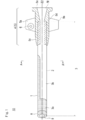
- FIG. 1 is a plan view of the catheter according to the first embodiment of the present invention.
- FIG. 2 is a cross-sectional view taken along the line AA'of the shaft of FIG.
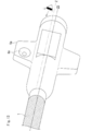
- FIG. 3 is an enlarged perspective view of the catheter and the hand portion of the first embodiment.
- FIG. 4 is an enlarged perspective view when the catheter of the first embodiment and the long axis of the hand portion are rotated by 180 ° about the central axis.
- FIG. 5 is a schematic cross-sectional view of blood vessels in the lower limbs.
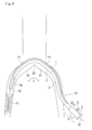
- FIG. 6 is a schematic cross-sectional view showing how the catheter of the first embodiment advances with the highly lubricated surface toward the outer inner surface of the curved blood vessel.
- FIG. 7 is a schematic cross-sectional view showing how the catheter of the first embodiment is placed with the low lubrication surface facing the outer inner surface of the curved blood vessel.
- FIG. 8 is a schematic cross-sectional view showing how the catheter of the first embodiment retracts with the highly lubricated surface toward the medial inner surface of the curved blood vessel.
- FIG. 9 is an enlarged perspective view of a hand portion according to a second embodiment of the present invention.
- FIG. 10 is an enlarged perspective view of a hand portion according to a first modification of the second embodiment of the present invention.
- FIG. 11 is an enlarged perspective view of a hand portion according to a modification 2 of the second embodiment of the present invention.
- FIG. 12 is an enlarged perspective view of a hand portion according to a modification 3 of the second embodiment of the present invention.
- FIG. 13 is an enlarged perspective view of a hand portion according to a third embodiment of the present invention.
- FIG. 14 is an enlarged perspective view of the side opposite to the central axis along the long axis of the hand portion according to the third embodiment of the present invention.
- FIG. 15 is a flowchart showing the steps of the treatment method of the present invention.
- “advance” means advancing the catheter from the blood vessel insertion port to the target site
- “backward” means returning the catheter to the blood vessel insertion port, that is, the hand side
- “indwelling” means inserting the catheter into the blood vessel. It means to fix it as it is.
- “Place on the outer surface at different positions” means to place the two elements on the outer surface of the catheter or hand without overlapping.
- the catheter 10 of the present embodiment shown in FIG. 1 is configured as a guiding sheath that conveys a treatment device (medical instrument) such as a balloon catheter, a stent installation catheter, and various embolic materials to a target site of a blood vessel. ing.
- a treatment device such as a balloon catheter, a stent installation catheter, and various embolic materials
- the catheter 10 includes a shaft 3, a soft tip 8 provided at the tip of the shaft 3, and a hub 5 as a hand portion 4 provided at the base end of the shaft 3.
- the shaft 3 is made of a flexible tubular body, and a shaft lumen (chamber) 9 is formed in the center of the shaft 3 over the entire length of the shaft 3.
- the shaft lumen 9 is opened at the opening at the tip of the soft tip 8.
- the catheter 10 is inserted into a blood vessel as a catheter assembly in which a hemostatic valve (not shown) is attached to a shaft 3 and a hub 5 and a dilator (not shown) is inserted.
- the dilator is withdrawn from the hub 5 and shaft 3 before inserting the treatment device into the catheter 10.
- the hemostatic valve may be left on or removed if necessary.
- the hub 5 has a hub tip portion 5c for fixing the shaft 3 inside, and the shaft 3 is fixed by insert molding.
- the hub 5 has a hub blue men 5f that opens at its base end and communicates with the inside of the shaft lumen 9.
- a long object such as a guide wire, a dilator, a catheter, an endoscope, an ultrasonic probe, and a temperature sensor can be inserted into the hub 5.
- various liquids such as a contrast medium, a chemical solution, and a physiological saline can be injected into the hub 5.
- the shaft 3 may be adhesively fixed in a lumen provided at the hub tip portion 5c of the hub 5 prepared as a separate member.
- the shaft 3 has a high lubrication surface 1 and a low lubrication surface on the outer surface at least a part of the outer surface along the long axis direction at the same position in the long axis direction of the shaft 3 but at different positions on the circumference. 2 is placed.
- the high lubrication surface 1 is a surface having a small frictional resistance with respect to the inner surface of the blood vessel, and is coated with a hydrophilic or hydrophobic lubricating resin provided on the outer surface of the shaft 3, or embossed on the outer surface. It is a product that has been processed to give unevenness. More specifically, the frictional resistance to the blood vessel is smaller than that of the outer surface of the uncoated or unprocessed shaft 3 near the base end of the catheter.
- the high lubrication surface 1 is formed in a planar shape along the long axis of the shaft 3.
- the shape of the highly lubricated surface 1 is not limited to a planar shape, and if the frictional resistance to the blood vessel is small, the lubricating resin or the embossed surface is separated and arranged in a plurality of linear lines, or a dotted line. , Or a collection of dots.
- a plurality of high lubrication surfaces 1 may be provided on the outer surface at different positions on the circumference of the shaft 3.
- the high lubrication surface 1 is made of a material that absorbs moisture and exhibits lubricity.
- the thickness of the lubricating layer can be appropriately set within a range in which sufficient lubricity can be obtained, and can be, for example, in the range of about 0.0001 mm to 0.02 mm.
- the hydrophilic polymer constituting the highly lubricated surface 1 include polyvinylpyrrolidone, polyvinyl alcohol, polyethylene oxide polymer, cellulosic polymer, acrylamide polymer, hyaluronic acid, polyacrylic acid, maleic anhydride polymer, and water-soluble polymer. Examples include sex nylons and derivatives thereof.
- these hydrophilic polymers are preferably crosslinked by adding an appropriate amount of a crosslinking agent or introducing an appropriate reactive functional group in order to firmly immobilize the surface of the outer layer 32.
- the tip portion 3a of the shaft 3 is not provided with the low lubrication surface 2, and only the high lubrication surface 1 is provided on the entire outer surface. This makes it easier for the catheter 10 to move through the bent blood vessel.
- the low lubrication surface 2 refers to a surface having a large frictional resistance to the inner surface of the blood vessel, and includes an uncoated or unprocessed outer surface of the catheter.
- a polymer having a photocurable functional group is applied to the entire outer surface of the shaft 3, a part is crosslinked, and then a part is masked and the non-masking part is further irradiated with light to crosslink. May be formed to form a low lubrication surface 2 having a larger frictional resistance than the masked portion.
- the masking portion may be a high lubrication surface 1 having a small frictional resistance.
- the shape of the low lubrication surface 2 is not limited to a planar shape, and the frictional resistance is larger than that of the high lubrication surface 1 such as a plurality of linearly spaced lines, a dotted line, or an aggregate of dots. Anything is fine. Alternatively, a plurality of them may be provided at different positions on the circumference.
- the portion is 0 to 500 mm, preferably 50 to 250 mm in the direction from the base end of the shaft to the tip end, and includes a portion composed of only the low lubrication surface 2 without providing the high lubrication surface 1.
- the catheter can also prevent the introducer and combined device from coming out of the hemostatic valve or penetration.
- the shaft 3 may be a single-layer resin tube, but as shown in the cross section AA'in FIG. 2, the shaft 3 has an inner layer 31 and an outer layer 32 in part, and a coil winding or a reinforcing wire of a blade structure is formed between the outer layers 32. It may have 33.
- the ratio of the length L1 of the high lubrication surface 1 and the length L2 of the low lubrication surface 2 to the entire circumference L1 + L2 may be arbitrary, but the ratio of the length of the high lubrication surface 1 on the circumference (L1 / L1 + L2) is It is 10 to 90%, more preferably 25 to 75%.
- the hub 5 has a hub tip portion 5c, a hub body portion 5d, a hub opening 5e, and a hub lumen 5f.
- the hub 5 is provided with a pair of wings 5a and 5b on the side surface, and the wing 5a has a marker 6 formed of a non-penetrating recess. It should be noted that the number of wings may be one, three or more, or not provided, instead of a pair (two).
- the marker 6 may be any one that can be recognized by sight, touch or perception such as shape, color, characters, symbols, surface irregularities or a combination thereof, and more preferably one that can be recognized by a plurality of senses.
- the ratio of L1 of the high lubrication surface 1 and the position and ratio of the color indicating the high lubrication surface 1 at the hand are made the same, or the hub on the high lubrication surface 1 side and the hub on the low lubrication surface 2 side are formed by two-color molding. You may change the color of the hub.
- the operator can visually recognize the position of the high lubrication surface 1 by the marker 6 and recognize the position of the high lubrication surface 1 of the catheter 10 in contact with the blood vessel.
- the marker 6 is located on the extension line Z extending along the long axis from the highly lubricated surface 1 provided on the shaft 3.
- the position of the highly lubricated surface 1 can be recognized at a glance by visually confirming the position of the marker 6.
- the position of the marker 6 can be confirmed by grasping the hub 5 and rotating the marker 6 with respect to the central axis Z2 along the long axis.
- the high lubrication surface 1 or the low lubrication surface 2 of the catheter 10 can be arranged at the position to be.
- the marker 6 is provided on the wing 5a provided on the hub 5, the position of the high lubrication surface 1 can be easily recognized by visually confirming the position of the wing 5a.
- the marker 6 since the marker 6 has a concave shape, the position of the highly lubricated surface 1 can be recognized by touch regardless of the visual sense. Therefore, it is not necessary to look at the hand portion 4 every time the operation is performed, which is more preferable because the procedure time can be shortened.
- the concave marker 6 is formed by transferring the gate mark or the shape of the gate when the hub 5 is injection-molded, so that the cost and time for separately providing the marker 6 can be shortened.
- the high lubrication surface 1 can be arranged on the side in contact with the blood vessel when advancing or retreating in the curved blood vessel Y, so that the frictional resistance with respect to the inner surface of the blood vessel can be reduced.
- the catheter 10 is placed to operate a treatment device (for example, a balloon catheter 11 described later)
- the low lubrication surface 2 is arranged on the side in contact with the blood vessel to prevent kickback of the catheter 10 due to the device operation. it can.
- the marker 6 may indicate the position of the low lubrication surface 2. As shown in FIG. 4, when the shaft 3 is inserted into the body, when the hub 5 is rotated by 180 ° about the central axis Z2 along the long axis, the position of the marker 6 is first with respect to the central axis Z2. Place it in the position opposite to the position of. In that case, the high lubrication surface 1 or the low lubrication surface 2 in the body is also arranged at the opposite positions.
- the catheter 10 operates as shown in FIGS. 5 to 8 below.
- This catheter 10 is introduced from, for example, one common femoral artery of the lower limb blood vessel shown in FIG. 5, and is placed across the aortic iliac artery bifurcation 24 and in front of the contralateral common femoral artery (contralateral puncture). ) Used in the method.
- the catheter 10 may be a guiding catheter, an introducer sheath, a contrast catheter, a microcatheter, or a guide wire support catheter. Further, the catheter 10 may be a balloon catheter, a stent delivery catheter, an atherectomy catheter, or a diagnostic imaging catheter including a reinforcing body.
- a catheter 10 in which a dilator (not shown) and a guide wire 12 are inserted into a shaft lumen 9 by puncturing the left common femoral artery 23 by the Seldinger method is preceded by the guide wire 12 with respect to the tip of the catheter 10.
- the tip of the catheter 10 is inserted into the left common femoral artery 23.
- the catheter 10 may be inserted from the radial artery of the arm (not shown) instead of the left common femoral artery 23.
- the lower limb artery on the same side as the lesion may be punctured (ipsilateral puncture), and a guiding catheter or a guiding catheter combined with an internal catheter may be provided via an introducer sheath (not shown).
- the catheter assembly may be inserted into the vessel.
- the shaft 3 has a tip 3a or a base 3b or Both of them are elastically deformed and curved.
- the shaft 3 comes into contact with the outer inner surface Y1 of the curved blood vessel Y in an attempt to widen so that the radius of curvature becomes larger due to the restoring force against elastic deformation.
- the highly lubricated surface 1 of the catheter 10 When the highly lubricated surface 1 of the catheter 10 is arranged so as to face the outer inner surface Y1, most of the outer surface of the shaft 3 in contact with the inner surface of the blood vessel becomes the highly lubricated surface 1. Therefore, the frictional resistance generated between the catheter 10 and the inner surface of the blood vessel is about the same as that of a catheter provided with a highly lubricated surface on the entire outer surface of the shaft 3. Therefore, it is possible to determine that the catheter 10 is advanced in the curved blood vessel Y, confirm the position of the marker 6, and advance the catheter 10 in the curved blood vessel Y.
- a treatment step a determination is made to advance the catheter 10, the position of the marker 6 is confirmed, and the high lubrication surface 1 is arranged so as to face the outer inner surface Y1 of the curved blood vessel Y. recognize. Carefully push the hub 5 of the catheter 10 forward into the curved blood vessel Y1.
- the shaft 3 is not arranged in a state suitable for advancing.
- the operator rotates the hub 5 with respect to the central axis Z2 along the long axis to rotate the catheter 10.
- the catheter 10 is advanced.
- the balloon catheter 11 which is a treatment device, is inserted into the shaft lumen 9 of the catheter 10. Friction resistance may occur when the balloon catheter 11 passes through the stenosis X in the right external iliac artery 26. In this case, the position of the catheter 10 may shift due to the kickback of the catheter, which is a reaction of friction. When the position shift occurs, the surgeon temporarily removes the balloon catheter 11 in order to return the catheter 10 to the target site and temporarily suspends the procedure, which increases the procedure time.
- the operator decides to place the catheter 10 in the blood vessel.
- the position of the marker 6 is the highly lubricated surface 1 of the shaft 3. Recognizes that it is arranged facing the inner inner surface Y2 of the curved blood vessel Y, in other words, recognizes that the low lubrication surface 2 of the shaft 3 faces the outer inner surface Y1 of the curved blood vessel Y.
- the shaft 3 of the catheter 10 tends to expand outward due to the reaction of the frictional resistance between the narrowed portion X and the balloon catheter 11.
- the catheter 10 is less likely to kick back and is stably placed without being displaced from the target site.
- the catheter 10 when it is determined to place the catheter 10 as a treatment step, the position of the marker 6 is confirmed, and it is recognized that the low lubrication surface 2 faces the outer inner surface Y1 of the curved blood vessel Y. , The catheter 10 is placed in the blood vessel, and the balloon catheter 11 is inserted to treat the stenosis X.
- the hub 5 is placed along the major axis Z2.
- the catheter 10 is placed after recognizing that the low lubrication surface 2 is facing the outer inner surface Y1 after confirming the position of the marker 6 again by rotating the axis with respect to the lower lubrication surface 2 toward the outer inner surface Y1. You may let me.
- the frictional resistance generated between the catheter 10 and the inner surface of the blood vessel is about the same as that of a catheter provided with a highly lubricated surface on the entire outer surface of the catheter shaft.
- the catheter 10 can be retracted and removed with a small frictional resistance to the inside of the curved blood vessel Y.
- the hub 5 is rotated about the central axis Z2 along the long axis, and the catheter 10 is rotated with respect to the long axis.
- the catheter 10 is retracted, recognizing that the high lubrication surface 1 faces the inner inner surface Y2.
- the catheter 10 is removed from the body, necessary measures such as hemostasis are performed, and the treatment is completed.
- the tip 3a of the shaft 3 is retracted to the aortic iliac artery bifurcation 24, and then the catheter 10 is further placed on the lower limb on the opposite side. You may proceed with the treatment and continue the treatment.
- FIG. 9 shows a second embodiment in which the kink-resistant protector 7 and the hub 5 are provided on the hand portion 4. Since the shaft 3 and the hub 5 are the same as those in the first embodiment, the description thereof will be omitted.
- the kink-resistant protector 7 includes a flexible portion 7a having a flexible tip to prevent the catheter from kinking at hand, and a body portion 7b that protects the base end portion of the catheter and can be fitted with the tip end portion of the hub 5.
- characters are described as information indicating the high lubrication surface 1 on the extension line Z extending from the high lubrication surface 1 along the long axis.
- the kink-resistant protector 7 can be described in large characters, and can be easily recognized visually or perceptually.
- the character indicating the high lubrication surface 1 is used as the first marker 6a, and the second marker 6a'is placed on the outer surface of the kink-resistant protector 7 at a position opposite to the central axis Z2 along the long axis of the kink-resistant protector 7. Characters may be described as information indicating the low lubrication surface 2.
- the first marker 6a or the second marker 6a' can be confirmed even if the hub 5 is rotated about the central axis Z2 along the long axis to change the direction, so that the highly lubricated surface can be confirmed.
- the position of 1 or the low lubrication surface 2 can be visually or perceptually recognized.
- a concave marker 6b may be provided as the first marker on the wing of the hub 5, and the character 6b'may be described on the kink-resistant protector 7 as the second marker.
- the position of the highly lubricated surface 1 can be visually and tactilely recognized.
- a concave first marker 6c is provided on the wing 5a of the hub 5, and information indicating the position of the highly lubricated surface 1 is provided on the hub body portion 5d as the second marker 6c'. It may be described. This makes it possible to visually and perceptually recognize the highly lubricated surface 1.
- information indicating the position of the low lubrication surface 2 may be described on the hub body portion 5d as a marker 6d.
- a second marker 6d' may be provided on the opposite side of the central axis Z2 along the long axis of the hub 5 with respect to the first marker showing the highly lubricated surface 1 of the modified example 3. This makes it possible to prevent mistakes caused by the operator's beliefs.
- the kink-resistant protector and the hub may be integrated to reduce the number of parts.
- the position of the high lubrication surface can be quickly recognized visually, tactilely and perceptually with one marker, shortening the procedure time, or depending on the operator's belief. You can prevent mistakes.
- the marker 6e is provided on the wing 5a at a position away from the extension line Z extending from the high lubrication surface 1.
- the hub is visually recognized, it can be easily visually recognized because the orientations of the highly lubricated surface 1 of the shaft 3 and the markers 6e provided on the wings 5a are the same.
- the first marker 6f showing the high lubrication surface 1 and the low lubrication surface 2 showing the low lubrication surface 2 on the opposite side symmetrical with respect to the central axis Z2 along the long axis of the hand portion.
- the marker 6f'of 2 may be provided.
- the treatment method using a catheter according to the present invention has a shaft 3 having a tip and a proximal end, and a hand portion 4 attached to the proximal end of the shaft 3, and the shaft 3 is at least one of the outer surfaces.
- the high lubrication surface 1 and the low lubrication surface 2 are provided in the portion, and the high lubrication surface 1 and the low lubrication surface are on the outer surface at the same position along the long axis of the shaft 3 but at different positions on the circumference. 2 is arranged, the marker 6 is provided on the outer surface of the hand portion 4, and the marker 6 prepares a catheter 10 indicating the position of the high lubrication surface 1 or the low lubrication surface 2.
- the treatment method comprises a step of determining forward, backward, or indwelling of the catheter 10 and a step of confirming the position of the marker 6.
- the catheter 10 by confirming the position of the marker 6 on the hand portion 4 as shown in FIG. 15, when the catheter 10 is advanced or retracted, the catheter 10 has frictional resistance against the inner surface of the blood vessel in contact with the catheter 10.
- the catheter 10 can be moved in a small state. Therefore, the catheter 10 can be advanced and retracted in a short time without trial and error.
- the frictional resistance between the catheter 10 and the blood vessel is increased to prevent kickback, thereby preventing the catheter 10 from being displaced and shortening the operation time.
- a step of rotating the hand portion 4 with respect to the central axis Z2 along the long axis to rotate the catheter 10 with respect to the long axis may have steps to advance, retract or indwell the catheter after recognizing the position of surface 1.
- the highly lubricated surface 1 or the highly lubricated surface 1 or the direction suitable for advancing, retreating or indwelling the catheter 10 The low lubrication surface 2 can be arranged to select a state of high frictional resistance and a state of low frictional resistance, and then the catheter 10 can be advanced, retracted or indwelled.
- the low lubrication surface 2 may be composed of a region in which the lubrication performance is deteriorated by forming the film thickness of the high lubrication surface 1 thinner than the others. Further, the low lubrication surface 2 may be covered with a material having a higher coefficient of friction than the material constituting the high lubrication surface 1.
Landscapes
- Health & Medical Sciences (AREA)
- Life Sciences & Earth Sciences (AREA)
- Biophysics (AREA)
- Pulmonology (AREA)
- Engineering & Computer Science (AREA)
- Anesthesiology (AREA)
- Biomedical Technology (AREA)
- Heart & Thoracic Surgery (AREA)
- Hematology (AREA)
- Animal Behavior & Ethology (AREA)
- General Health & Medical Sciences (AREA)
- Public Health (AREA)
- Veterinary Medicine (AREA)
- Media Introduction/Drainage Providing Device (AREA)
Priority Applications (1)
| Application Number | Priority Date | Filing Date | Title |
|---|---|---|---|
| JP2021508737A JPWO2020194907A1 (https=) | 2019-03-26 | 2019-12-12 |
Applications Claiming Priority (2)
| Application Number | Priority Date | Filing Date | Title |
|---|---|---|---|
| JP2019059442 | 2019-03-26 | ||
| JP2019-059442 | 2019-03-26 |
Publications (1)
| Publication Number | Publication Date |
|---|---|
| WO2020194907A1 true WO2020194907A1 (ja) | 2020-10-01 |
Family
ID=72609389
Family Applications (1)
| Application Number | Title | Priority Date | Filing Date |
|---|---|---|---|
| PCT/JP2019/048758 Ceased WO2020194907A1 (ja) | 2019-03-26 | 2019-12-12 | カテーテル、および治療方法 |
Country Status (2)
| Country | Link |
|---|---|
| JP (1) | JPWO2020194907A1 (https=) |
| WO (1) | WO2020194907A1 (https=) |
Cited By (2)
| Publication number | Priority date | Publication date | Assignee | Title |
|---|---|---|---|---|
| JP2024024933A (ja) * | 2022-08-10 | 2024-02-26 | テルモ株式会社 | カテーテル |
| WO2025186739A1 (en) * | 2024-03-08 | 2025-09-12 | Baylis Medical Technologies Inc. | Method for selectively accessing a target vessel using an articulating device |
Citations (9)
| Publication number | Priority date | Publication date | Assignee | Title |
|---|---|---|---|---|
| US4362156A (en) * | 1979-04-18 | 1982-12-07 | Riverain Corporation | Intravenous infusion assembly |
| JP2003154014A (ja) * | 2001-11-21 | 2003-05-27 | Terumo Corp | 導入用シース位置決め器具 |
| JP2003164529A (ja) * | 2001-12-03 | 2003-06-10 | Nippon Sherwood Medical Industries Ltd | 中心静脈カテーテル用スタイレット |
| JP2003284780A (ja) * | 2002-03-28 | 2003-10-07 | Terumo Corp | スタイレット付きカテーテル |
| JP2008504941A (ja) * | 2004-05-18 | 2008-02-21 | カイフォン インコーポレイテッド | 挿入装置および使用方法 |
| WO2015046148A1 (ja) * | 2013-09-30 | 2015-04-02 | テルモ株式会社 | カテーテル |
| JP2015066331A (ja) * | 2013-09-30 | 2015-04-13 | テルモ株式会社 | カテーテル |
| JP2015516628A (ja) * | 2012-03-23 | 2015-06-11 | シー・アール・バード・インコーポレーテッドC R Bard Incorporated | 挿入可能な医療器具の特徴情報を提供する標識 |
| WO2015146408A1 (ja) * | 2014-03-28 | 2015-10-01 | テルモ株式会社 | カテーテル組立体および内カテーテル |
-
2019
- 2019-12-12 JP JP2021508737A patent/JPWO2020194907A1/ja active Pending
- 2019-12-12 WO PCT/JP2019/048758 patent/WO2020194907A1/ja not_active Ceased
Patent Citations (9)
| Publication number | Priority date | Publication date | Assignee | Title |
|---|---|---|---|---|
| US4362156A (en) * | 1979-04-18 | 1982-12-07 | Riverain Corporation | Intravenous infusion assembly |
| JP2003154014A (ja) * | 2001-11-21 | 2003-05-27 | Terumo Corp | 導入用シース位置決め器具 |
| JP2003164529A (ja) * | 2001-12-03 | 2003-06-10 | Nippon Sherwood Medical Industries Ltd | 中心静脈カテーテル用スタイレット |
| JP2003284780A (ja) * | 2002-03-28 | 2003-10-07 | Terumo Corp | スタイレット付きカテーテル |
| JP2008504941A (ja) * | 2004-05-18 | 2008-02-21 | カイフォン インコーポレイテッド | 挿入装置および使用方法 |
| JP2015516628A (ja) * | 2012-03-23 | 2015-06-11 | シー・アール・バード・インコーポレーテッドC R Bard Incorporated | 挿入可能な医療器具の特徴情報を提供する標識 |
| WO2015046148A1 (ja) * | 2013-09-30 | 2015-04-02 | テルモ株式会社 | カテーテル |
| JP2015066331A (ja) * | 2013-09-30 | 2015-04-13 | テルモ株式会社 | カテーテル |
| WO2015146408A1 (ja) * | 2014-03-28 | 2015-10-01 | テルモ株式会社 | カテーテル組立体および内カテーテル |
Cited By (3)
| Publication number | Priority date | Publication date | Assignee | Title |
|---|---|---|---|---|
| JP2024024933A (ja) * | 2022-08-10 | 2024-02-26 | テルモ株式会社 | カテーテル |
| JP7841981B2 (ja) | 2022-08-10 | 2026-04-07 | テルモ株式会社 | カテーテル |
| WO2025186739A1 (en) * | 2024-03-08 | 2025-09-12 | Baylis Medical Technologies Inc. | Method for selectively accessing a target vessel using an articulating device |
Also Published As
| Publication number | Publication date |
|---|---|
| JPWO2020194907A1 (https=) | 2020-10-01 |
Similar Documents
| Publication | Publication Date | Title |
|---|---|---|
| US12478770B2 (en) | Methods and devices for transcarotid access | |
| US11759613B2 (en) | Methods and devices for transcarotid access | |
| JP7539515B2 (ja) | 経頸動脈アクセスの方法とデバイス | |
| WO2020194907A1 (ja) | カテーテル、および治療方法 | |
| WO2021044923A1 (ja) | カテーテル | |
| US20150088152A1 (en) | Elongated member for medical use | |
| WO2023157440A1 (ja) | ダイレータとカテーテル組立体およびカテーテル組立体の操作方法 | |
| JP2023116319A (ja) | カテーテル | |
| WO2021246030A1 (ja) | カテーテルおよび治療方法 | |
| US20250332381A1 (en) | Catheter and catheter system | |
| JP2023156544A (ja) | カテーテルおよびガイディングデバイス | |
| WO2024171569A1 (ja) | サポートカテーテルおよびこれを用いた治療方法 | |
| WO2024080003A1 (ja) | カテーテル及びカテーテルシステム | |
| CN120227220A (zh) | 一种引导头结构及输送系统 | |
| JP2023100131A (ja) | バルーンカテーテル | |
| HK40029207B (en) | Methods and devices for transcarotid access | |
| HK40029207A (en) | Methods and devices for transcarotid access | |
| HK1240869B (en) | Devices for transcarotid access | |
| HK1240869A1 (en) | Devices for transcarotid access |
Legal Events
| Date | Code | Title | Description |
|---|---|---|---|
| 121 | Ep: the epo has been informed by wipo that ep was designated in this application |
Ref document number: 19921042 Country of ref document: EP Kind code of ref document: A1 |
|
| ENP | Entry into the national phase |
Ref document number: 2021508737 Country of ref document: JP Kind code of ref document: A |
|
| NENP | Non-entry into the national phase |
Ref country code: DE |
|
| 122 | Ep: pct application non-entry in european phase |
Ref document number: 19921042 Country of ref document: EP Kind code of ref document: A1 |