WO2020194669A1 - 重ねレーザ溶接継手とその製造方法および自動車車体用構造部材 - Google Patents
重ねレーザ溶接継手とその製造方法および自動車車体用構造部材 Download PDFInfo
- Publication number
- WO2020194669A1 WO2020194669A1 PCT/JP2019/013632 JP2019013632W WO2020194669A1 WO 2020194669 A1 WO2020194669 A1 WO 2020194669A1 JP 2019013632 W JP2019013632 W JP 2019013632W WO 2020194669 A1 WO2020194669 A1 WO 2020194669A1
- Authority
- WO
- WIPO (PCT)
- Prior art keywords
- joint
- welded
- welding
- mass
- linear
- Prior art date
- Legal status (The legal status is an assumption and is not a legal conclusion. Google has not performed a legal analysis and makes no representation as to the accuracy of the status listed.)
- Ceased
Links
Images



Classifications
-
- B—PERFORMING OPERATIONS; TRANSPORTING
- B23—MACHINE TOOLS; METAL-WORKING NOT OTHERWISE PROVIDED FOR
- B23K—SOLDERING OR UNSOLDERING; WELDING; CLADDING OR PLATING BY SOLDERING OR WELDING; CUTTING BY APPLYING HEAT LOCALLY, e.g. FLAME CUTTING; WORKING BY LASER BEAM
- B23K26/00—Working by laser beam, e.g. welding, cutting or boring
- B23K26/20—Bonding
- B23K26/21—Bonding by welding
- B23K26/24—Seam welding
- B23K26/244—Overlap seam welding
-
- B—PERFORMING OPERATIONS; TRANSPORTING
- B23—MACHINE TOOLS; METAL-WORKING NOT OTHERWISE PROVIDED FOR
- B23K—SOLDERING OR UNSOLDERING; WELDING; CLADDING OR PLATING BY SOLDERING OR WELDING; CUTTING BY APPLYING HEAT LOCALLY, e.g. FLAME CUTTING; WORKING BY LASER BEAM
- B23K26/00—Working by laser beam, e.g. welding, cutting or boring
- B23K26/20—Bonding
- B23K26/21—Bonding by welding
-
- B—PERFORMING OPERATIONS; TRANSPORTING
- B23—MACHINE TOOLS; METAL-WORKING NOT OTHERWISE PROVIDED FOR
- B23K—SOLDERING OR UNSOLDERING; WELDING; CLADDING OR PLATING BY SOLDERING OR WELDING; CUTTING BY APPLYING HEAT LOCALLY, e.g. FLAME CUTTING; WORKING BY LASER BEAM
- B23K26/00—Working by laser beam, e.g. welding, cutting or boring
- B23K26/20—Bonding
- B23K26/21—Bonding by welding
- B23K26/24—Seam welding
- B23K26/28—Seam welding of curved planar seams
-
- B—PERFORMING OPERATIONS; TRANSPORTING
- B23—MACHINE TOOLS; METAL-WORKING NOT OTHERWISE PROVIDED FOR
- B23K—SOLDERING OR UNSOLDERING; WELDING; CLADDING OR PLATING BY SOLDERING OR WELDING; CUTTING BY APPLYING HEAT LOCALLY, e.g. FLAME CUTTING; WORKING BY LASER BEAM
- B23K35/00—Rods, electrodes, materials, or media, for use in soldering, welding, or cutting
- B23K35/22—Rods, electrodes, materials, or media, for use in soldering, welding, or cutting characterised by the composition or nature of the material
- B23K35/24—Selection of soldering or welding materials proper
- B23K35/30—Selection of soldering or welding materials proper with the principal constituent melting at less than 1550°C
- B23K35/3053—Fe as the principal constituent
- B23K35/3073—Fe as the principal constituent with Mn as next major constituent
-
- B—PERFORMING OPERATIONS; TRANSPORTING
- B23—MACHINE TOOLS; METAL-WORKING NOT OTHERWISE PROVIDED FOR
- B23K—SOLDERING OR UNSOLDERING; WELDING; CLADDING OR PLATING BY SOLDERING OR WELDING; CUTTING BY APPLYING HEAT LOCALLY, e.g. FLAME CUTTING; WORKING BY LASER BEAM
- B23K2101/00—Articles made by soldering, welding or cutting
- B23K2101/006—Vehicles
Definitions
- the present invention relates to a lap laser welded joint, a manufacturing method thereof, and a structural member for an automobile body having the above lap laser welded joint.
- Resistance spot welding is generally used for welding structural members (strength members) of automobile bodies having flanges.
- resistance spot welding takes a long time to weld, the amount of heat generated decreases due to diversion, so the welding pitch cannot be narrowed, and a certain amount of space is required to set the welding gun.
- lap laser welding refers to a welding method in which one side surface of a plurality of lapped steel sheets is irradiated with a laser beam to melt and join the steel sheets.
- a laser beam is intermittently irradiated on the surface of a plurality of stacked steel plates, and the steel plate at the portion irradiated with the laser beam is melted and solidified to form a linear joint having a short length.
- a plurality of steel plates were joined by forming a welded portion in which the portions were continuously arranged in a row.
- lap laser beam welding has a problem that cracks are likely to occur in the final solidified portion on the welding end portion side of the linear joint portion. When a crack occurs, it propagates over the entire length of the linear joint, so that not only the static strength such as the shear strength and the peel strength of the welded joint is lowered, but also the fatigue strength is remarkably lowered.
- Patent Document 1 discloses a technique for preventing welding cracks by projecting a steel plate on the lower side of lap welding and setting the welding start position to a position away from the flange end.
- Patent Document 2 discloses a technique of irradiating the end portion of the overlapping surface with a laser at an angle to prevent welding cracks.
- Patent Documents 3 and 4 disclose a technique for preventing welding cracks by reheating or welding a portion once welded and the periphery of the welded portion.
- Patent Document 5 discloses a technique for preventing the occurrence of welding cracks by welding the overlapping surfaces in an elliptical shape.
- Patent Document 6 discloses a technique for preventing the occurrence of weld cracks by optimizing the steel sheet component and optimizing the ratio of the weld bead width to the bead thickness.
- JP-A-2007-229740 Japanese Unexamined Patent Publication No. 2008-296236 Japanese Unexamined Patent Publication No. 2012-240083 Japanese Unexamined Patent Publication No. 2012-24806 Japanese Unexamined Patent Publication No. 2017-113781 JP-A-2018-001197
- Patent Document 5 is to weld the overlapping surfaces in an elliptical shape, and cannot be applied to prevent cracking of the welded end portion of the linear joint portion.
- Patent Document 6 has a problem that it is not possible to prevent the occurrence of cracks at the welding end portion of a linear joint portion having a short length because stress tends to be concentrated on the welding end portion. ..
- the present invention has been made in view of the above-mentioned problems of the prior art, and an object of the present invention is welding in which short-length joints (welding points) are formed in a row by intermittently irradiating a laser beam.
- first joint an initially formed linear joint
- subsequent joints one or more linear joints
- the shape of the first joint is J-shaped, and the weld start of the first joint and the subsequent welds adjacent to it.
- the welded portion is formed so that the welded end portion of the joint portion faces and the weld start end portion of the subsequent joint portion and the weld end portion of the subsequent joint portion formed adjacent thereto face each other. It is important to form the welded portion so that the welded start portion and the welded end portion of the joint portions face each other, and further, cracking of the welded end portion of the joint portion is more reliably prevented and sufficient.
- the total gap G between the steel plates constituting the welded portion is the total thickness T of the steel plates constituting the welded portion.
- the welded portion is in the range of 0 to 15%, and the welded portion is composed of a linear first joint portion and a linear subsequent joint portion arranged in a row following the first joint portion.
- the portion has a J-shape composed of a linear joint portion and an arc-shaped or circular curved joint portion connected to the weld end portion side of the linear joint portion, and the welded portion is described below. Equations (1) to (4); 15.0 ⁇ L 1 ⁇ 30.0 ... (1) 8.0 ⁇ L 2 ⁇ 20.0 ... (2) 1/8 ⁇ w / b ⁇ 1/2 ... (3) 1/4 ⁇ a / (L 1 + L 2 ) ⁇ 1/2 or 1/2 ⁇ a / L 2 ⁇ 1 ...
- L 1 Length of the first joint (mm)
- L 2 Length of subsequent joint (mm)
- b Minimum thickness (mm) of molten metal at the joint
- w Width of molten metal at the joint (mm)
- a Shortest distance between joints (mm) It is a lap laser welded joint characterized by satisfying all of the above.
- the first joint portion is composed of only a linear joint portion, and instead of the above formula (1), the following formula (1'); 30.0 ⁇ L 1' ⁇ 40.0 ... (1')
- L 1' length of the linear joint (mm) It is characterized by satisfying.
- At least one of the above steel sheets has C: 0.07 to 0.4 mass%, Si: 0.2 to 3.5 mass%, Mn: 1.8 to 5. It is characterized by containing 5 mass%, P + S: 0.03 mass% or less, Al: 0.08 mass% or less, and N: 0.010 mass% or less, and the balance having a component composition consisting of Fe and unavoidable impurities.
- the steel sheet in the lap laser welded joint of the present invention further has the following groups A and B; -Group A: 1 or 2 selected from Ti: 0.0005 to 0.01 mass% and Nb: 0.005 to 0.050 mass%-Group B: Cr: 1.0 mass% or less, Mo: 0 It is characterized by containing at least one group of components selected from .50 mass% or less and B: 0.10 mass% or less.
- the lap laser welded joint of the present invention is characterized in that at least one of the above steel sheets is a high-tensile steel sheet having a tensile strength of 980 MPa or more.
- a plurality of steel plates are superposed on top of each other, and a laser beam is intermittently irradiated on one side surface of the superposed steel plates, following the linear first joint portion and the first joint portion thereof.
- the total gap G between the steel plates forming the welded portion is set to 0 to 15% of the total thickness T of the steel plates forming the welded portion.
- the welding start end of the first joint and the subsequent joint adjacent to the first joint is opposed to each other, and the welding start end portion and the welding end portion of the subsequent joint portions are opposed to each other, and the shape of the first joint portion is a linear joint portion and its linear shape. It has a J-shape consisting of an arc-shaped or circular curved joint connected to the welding end side of the joint, and the weld is further represented by the following equations (1) to (4); 15.0 ⁇ L 1 ⁇ 30.0 ... (1) 8.0 ⁇ L 2 ⁇ 20.0 ...
- L 1 Length of the first joint (mm)
- L 2 Length of subsequent joint (mm)
- b Minimum thickness (mm) of molten metal at the joint
- w Width of molten metal at the joint (mm)
- a Shortest distance between joints (mm)
- the first joint portion is composed of only a linear joint portion, and instead of the above formula (1), the following formula (1'); 30.0 ⁇ L 1' ⁇ 40.0 ... (1')
- L 1' length of the linear joint (mm) It is characterized by controlling at least one of laser power, focal position, welding speed and beam diameter so as to satisfy.
- the present invention is a structural member for an automobile body having the lap laser welded joint according to any one of the above.
- the present invention it is possible not only to surely suppress the occurrence of cracks at the weld end portion of the joint portion constituting the welded portion of the laminated laser welded joint in which a plurality of laminated steel plates are laser beam welded, but also to suppress the occurrence of cracks in the welded portion. It is possible to manufacture a lap laser welded joint having excellent peeling strength. Further, since the lap laser welded joint of the present invention can shorten the length of the joint portion, the degree of freedom in component design is increased, and it is possible to develop a member having lighter weight, higher rigidity and higher strength. Therefore, the lap laser welded joint of the present invention can be preferably applied to a structural member (strength member) which is a skeleton of an automobile body.
- FIG. 1 is a perspective view showing an example of a conventional lap laser welded joint.
- the lap laser welded joint 1 is formed by stacking at least two steel plates, and in the example shown in FIG. 1, a cross-sectional shape having a vertical wall portion 2a and a flange portion 2b extending outward from the tip of the vertical wall portion 2a.
- Welding is performed by irradiating the surface of the flange portion 2b from above with a laser beam to form at least a molten portion (molten metal portion) penetrating the steel plate 2 and solidifying the surface to form a joint portion (welding point). ing.
- molten portion molten metal portion
- welding point welding point
- the welded portion of the lap laser welded joint 1 moves the welding head WH, which is a laser beam source, along the length direction of the vertical wall portion 2a (the direction of the arrow in FIG. 1), and transfers the laser beam to the flange portion 2b. It is formed by intermittently irradiating the surface. As a result, as shown in FIG. 1, a short linear first joint portion 4 and subsequent joint portion 5 are continuously formed on the joint surface of the steel plate 2. When the length of the flange portion is short, there may be only one subsequent joint portion 5, but when the length of the flange portion is long, a plurality of subsequent joint portions 5 are formed in a row along the length direction of the flange portion. As described above, in the present invention, the above-mentioned "first joint portion” and “subsequent joint portion” are collectively referred to as simply "joint portion".
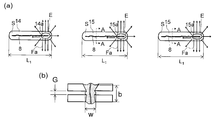
- FIG. 2 is a schematic view showing a conventional welded portion formed on the flange portion 2b of the lap laser welded joint shown in FIG. 1, and FIG. 2A shows the first joint portion 14 constituting the welded portion and the first joint portion 14 thereof.
- a crack 8 is generated in the weld end portion E of the first joint portion 14 and the subsequent joint portion 15, and then propagates from the weld end portion E to the weld start end portion S of the welded portion.
- the peeling strength and the fatigue strength are significantly impaired. Cracks generated at the welding end can be prevented by making the length of the first joint 14 and the subsequent joint 15 sufficient, but this method increases the welding time and produces. There is another problem that leads to sexual deterioration.
- the cracking of the welding end portion occurs through the welding end portion (final solidification portion) of the first joint portion 14 and the subsequent joint portion 15 from the front surface to the back surface, and the presence or absence of such cracking should be visually confirmed.
- the welding end of the joint after welding is cut in the width direction, and the cut surface is observed with an optical microscope, for example, at a magnification of about 10 times. Is preferable.
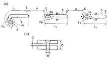
- FIG. 3 is a schematic view showing a welded portion of the present invention formed on the flange portion 2b of the same laminated laser welded joint as shown in FIG. 2, and FIG. 3A constitutes a welded portion.
- the feature of the welded portion of the present invention is that the weld start end portion of the first joint portion 4 and the weld end portion of the subsequent joint portion 5 adjacent thereto face each other and the subsequent joint portion 5 It means that the welding start end portion and the welding end portion of the subsequent joint portion 5 adjacent thereto face each other, that is, the welding start end portion and the welding end portion of the adjacent joint portions face each other.
- the inventors have further studied a method for suppressing cracking at the welded end of the first joint.
- the shape of the first joint is formed by connecting the linear joint and the end side of the joint to form an arc or a circle. It was found that it is effective to make a J-shape consisting of a curved joint.
- the welded end side of the first joint that is, the steel plate around the welded end of the curved joint is already constrained by the linear weld, so that it is the center of the final solidified part.
- the tensile stress (force in the direction of the arrow Fc shown in FIG. 3A) from the outer peripheral portion of the molten portion applied to the portion (4a) to the outside is reduced, and cracking at the welding end portion of the first joint portion can be prevented. ..
- FIG. 3 shows an example in which the welded portion of the present invention shown in FIG. 3 is applied to the lap laser welded joint shown in FIG.
- the total gap G between the steel plates constituting the welded portion is within the range of 0 to 15% of the total thickness T of the steel plates constituting the welded portion, and the welding is performed.
- the portions, that is, the first joint portion and the subsequent joint portion constituting the welded portion are the following equations (1) to (4); 15.0 ⁇ L 1 ⁇ 30.0 ... (1) 8.0 ⁇ L 2 ⁇ 20.0 ... (2) 1/8 ⁇ w / b ⁇ 1/2 ...
- L 1 Length of the first joint (mm)
- L 2 Length of subsequent joint (mm)
- b Minimum thickness (mm) of molten metal at the joint
- w Width of molten metal at the joint (mm)
- a Shortest distance between joints (mm)
- the ratio (G / T) of the total gap G between the steel plates constituting the welded portion to the total thickness T of the steel plates constituting the welded portion is 0 to 0.15, that is, the welded portion. It is necessary that the ratio of the total gap G between the steel plates constituting the welded portion to the total thickness T of the steel plates constituting the above is in the range of 0 to 15%. This is because when the ratio of G to T exceeds 15%, the depth of the crater at the welding end portion becomes deeper, and stress is more likely to be concentrated. It is preferably in the range of 0 to 10%.
- the shape of the first joint portion is formed into a linear joint portion and an arc shape.
- the length L 1 of the first joint must be in the range of 15.0 to 30.0 mm.
- the length L 1 of the J-shaped first joint is the total length of the linear joint and the curved joint, as shown in FIG.
- L 1 is shorter than 15.0 mm, cracks occur at the welded end of the first joint. It is preferably 20.0 mm or more.
- the upper limit of L 1 is not limited from the viewpoint of preventing cracking, but is set to 30.0 mm or less from the viewpoint of shortening the welding time. It is preferably 25.0 mm or less.
- the length L 2 of the subsequent joint portion constituting the welded portion needs to be in the range of 8.0 to 20.0 mm.
- L 2 is shorter than 8.0 mm, even if the welding start end of the preceding joint and the welding end of the trailing joint face each other, a welding area sufficient to relieve the stress applied to the welding end is secured. Therefore, it is not possible to reliably prevent cracking at the welding end.
- It is preferably 10.0 mm or more.
- the upper limit of L 2 is not limited from the viewpoint of preventing cracking, but is set to 20.0 mm or less from the viewpoint of shortening the welding time. It is preferably 15.0 mm or less.
- the ratio (w / b) of the width w of the molten metal of the joint to the minimum thickness b generated at the weld end (final solidification) of the joint constituting the weld is 1. It needs to be in the range of / 8 to 1/2.
- the tensile stress from the outer peripheral portion of the molten portion to the outer side of the final solidified portion of the weld end portion of the first joint portion and the subsequent joint portion becomes large, and the weld cracks The occurrence cannot be suppressed.
- the ratio (w / b) at the joint is in the range of 1/8 to 1/2.
- the preferred ratio (w / b) is in the range of 1/6 to 1/3.
- the ratio (a / (L 1 + L 2 )) is greater than 1/2, or if the ratio (a / L 2 ) is greater than 1, the subsequent joint is from the preceding joint of that joint.
- the effect of suppressing the deformation of the steel plate around the joint cannot be sufficiently obtained, and the cracking of the welded end cannot be prevented.
- the lower limit of a is not limited from the viewpoint of preventing cracking, but from the viewpoint of shortening the welding time, the above ratio (a / (L 1 + L 2 )) is 1/4 or more, and the above ratio ( a / L 2 ) shall be 1/2 or more.
- the preferable ratio (a / (L 1 + L 2 )) is in the range of 1/3 to 2/5, and the preferable ratio (a / L 2 ) is in the range of 3/5 to 9/10.
- the length L 1'of the first joint is the following formula (1') instead of the above-mentioned formula (1); 30.0 ⁇ L 1' ⁇ 40.0 ... (1')
- L 1' length of the linear joint (mm) It is necessary to meet.
- the upper limit of L 1' is not limited from the viewpoint of preventing cracking, but is set to 40.0 mm or less from the viewpoint of shortening the welding time. It is preferably 38.0 mm or less.
- FIGS. 1 to 4 show an example in which two steel plates are superposed to form a laser welded joint, it goes without saying that three or more steel plates may be superposed to form a welded joint. is there.
- the steel plate constituting the lap laser welded joint of the present invention has a thickness of 0.5 to 3.2 mm, which is generally used as an outer plate of an automobile body and a structural member (strength member). Anything within the range of is not particularly limited.
- the plurality of steel plates may all have the same plate thickness, or may have different plate thicknesses.
- the plate thickness t 2 of the upper steel plate 2 is 0.6 to 1.8 mm
- the plate thickness t 3 of the lower steel plate 3 is 1.
- 0 may be in the range of ⁇ 2.5 mm
- the thickness t 3 of the thickness t 2 and the lower of the steel plate 3 of the upper steel plate 2 may be a thickness of the same 0.5 ⁇ 3.2 mm.
- compositional Composition of Steel Sheets The composition of a plurality of steel sheets constituting the lap laser welded joint of the present invention is not particularly limited, but at least one steel sheet has C: 0.07 to 0, as described below. Contains 4 mass%, Si: 0.2 to 3.5 mass%, Mn: 1.8 to 5.5 mass%, P + S: 0.03 mass% or less, Al: 0.08 mass% or less, and N: 0.010 mass% or less. However, it is preferable that the balance has a component composition of Fe and unavoidable impurities.
- C 0.07 to 0.4 mass% C is an element effective for improving the strength of steel, and by containing 0.07 mass% or more, the effects of precipitation strengthening and transformation strengthening can be obtained. Further, by setting the C content to 0.4 mass% or less, desired strength and processability can be ensured without causing precipitation of coarse carbides. Therefore, the C content is preferably in the range of 0.07 to 0.4 mass%. More preferably, it is in the range of 0.15 to 0.3 mass%.
- Si 0.2-3.5 mass%
- Si is an element having an excellent solid solution strengthening ability, and the strength of steel can be increased by containing 0.2 mass% or more. Further, by setting the Si content to 3.5 mass% or less, it is possible to suppress excessive hardening of the weld heat-affected zone and prevent deterioration of the toughness and low-temperature crack resistance of the weld heat-affected zone. Therefore, the Si content is preferably in the range of 0.2 to 3.5 mass%. More preferably, it is in the range of 1.0 to 2.5 mass%.
- Mn 1.8-5.5 mass%
- Mn is an element effective for improving hardenability and suppressing precipitation of coarse carbides, and is preferably contained in an amount of 1.8 mass% or more. Further, by setting the Mn content to 5.5 mass% or less, it is possible to suppress an increase in grain boundary embrittlement sensitivity and prevent deterioration of toughness and low temperature crack resistance. Therefore, the Mn content is preferably in the range of 1.8 to 5.5 mass%. More preferably, it is in the range of 2.0 to 3.5 mass%.
- P and S are harmful elements that adversely affect the ductility and toughness of steel.
- the total content of P and S is preferably 0.03 mass% or less. More preferably, it is 0.02 mass% or less.
- Al 0.08 mass% or less
- Al is an element added as a deoxidizer at the stage of steelmaking, and is generally added in an amount of 0.01 mass% or more.
- the Al content exceeds 0.08 mass%, inclusions such as alumina increase, and an adverse effect on fatigue resistance becomes apparent. Therefore, the Al content is 0.08 mass% or less. It is preferably in the range of 0.02 to 0.07 mass%.
- N 0.010 mass% or less
- N is an element that greatly deteriorates the aging resistance of steel, and it is preferable to reduce it as much as possible.
- the N content is set to 0.010 mass% or less.
- the lower limit of N is not particularly limited, it is preferably about 0.001 mass% from the viewpoint of preventing an increase in manufacturing cost.
- At least one steel plate constituting the welded joint of the present invention has the following group A and B for the purpose of further improving the strength of the steel plate and the peel strength of the welded portion in addition to the above-mentioned composition. It is preferable to contain at least one group of components.
- Ti and Nb form carbides and nitrides and precipitate. However, it has the effect of suppressing the coarsening of austenite during annealing during steel sheet production. In order to obtain the above effect, it is preferable that one or two kinds selected from Ti and Nb are contained in an amount of 0.0005 mass% or more for Ti and 0.005 mass% or more for Nb. However, even if Ti and Nb are excessively contained, the above effects are saturated and the raw material cost is only increased.
- Ti and / or Nb it is preferable that Ti is 0.01 mass% or less and Nb is 0.050 mass% or less. More preferable contents are in the range of Ti: 0.0006 to 0.0080 mass% and Nb: 0.010 to 0.040 mass%.
- Group B One or more selected from Cr: 1.0 mass% or less, Mo: 0.50 mass% or less, and B: 0.10 mass% or less Cr, Mo, and B have steel hardenability. It is an element effective for improving, and in order to obtain the above effect, one or more of Cr: 0.01 mass% or more, Mo: 0.004 mass% or more, and B: 0.0001 mass% or more are contained. Is preferable. However, even if these elements are excessively contained, the above-mentioned effect is saturated and only the raw material cost is increased. Therefore, when Cr, Mo and B are contained, it is preferable to add Cr: 1.0 mass% or less, Mo: 0.50 mass% or less, and B: 0.10 mass% or less. More preferably, it is in the range of Cr: 0.02 to 0.50 mass%, Mo: 0.01 to 0.10 mass%, and B: 0.001 to 0.03 mass%.
- the balance other than the above components is Fe and unavoidable impurities.
- At least one of the plurality of steel sheets constituting the lap laser welded joint of the present invention is preferably a high-tensile steel sheet having a tensile strength TS of 980 MPa or more. If at least one steel plate is the above-mentioned high-tensile steel plate, the lap laser welded joint can obtain high joint strength, and even if welding cracks occur by the conventional welding method, in the present invention, the preceding joint portion It is possible to prevent the occurrence of weld cracks due to the effect of suppressing the deformation of the steel plate around the joint due to the above.
- At least one of the plurality of steel sheets has the above-mentioned component composition and has a tensile strength TS of 980 MPa or more.
- the plurality of steel sheets constituting the lap laser beam welded joint of the present invention may be steel sheets having the same composition and the same strength, or steel sheets having different components and different strengths.
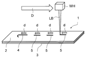
- FIG. 5 is a diagram illustrating an example of a welding method used for manufacturing the lap laser welded joint of the present invention.
- a plurality of steel plates are stacked one above the other, and the uppermost steel plate surface of the plurality of stacked steel plates is intermittently irradiated with a laser beam to form a first joint portion.
- a welded portion is formed and manufactured by sequentially forming 4 and a plurality of subsequent joint portions 5 following it.
- one-side welding is performed on a plurality of stacked steel plates.
- the work space required for welding can be reduced.
- the laser beam may be irradiated from any steel plate side.
- two steel plates 2 and 3 are overlapped to form a joint surface, and a laser beam is intermittently irradiated on the joint surface to form a J-shaped first.
- a joint portion 4 and a plurality of linear subsequent joint portions 5 are formed thereafter.
- the ratio of the total gap G between the steel plates constituting the welded portion to the total thickness T of the steel plates constituting the welded portion (G / T). Is 0 to 0.15, that is, the ratio of the total gap G between the steel plates forming the welded portion to the total thickness T of the steel plates forming the welded portion is set within the range of 0 to 15%. This is because when the ratio of G to T exceeds 15%, the depth of the crater at the welding end portion becomes deeper, and stress is more likely to be concentrated. It is preferably in the range of 0 to 10%.
- the laser beam LB when the laser beam LB is irradiated to the steel plate surface while moving the welding head WH for irradiating the laser beam in the welding direction (the direction indicated by D in FIG. 5), the laser beam LB
- the scanning direction of the welding head WH is opposite to the moving direction of the welding head WH (the direction opposite to the arrow shown by D in FIG. 5).
- the welding start end of the succeeding joint 4 and the welding end of the succeeding joint 4 adjacent thereto are opposed to each other, that is, the welding start and the welding end of the adjacent joint are opposed to each other. Since the welded portion can be formed as described above, it is possible to prevent cracking of the welded end portion of the joint portion.
- the shape of the first joint portion 4 is an arc shape or a circular shape connecting the linear joint portion and the welding end portion side of the linear joint portion. It is important to have a J-shape consisting of curved joints. This makes it possible to prevent cracks that occur at the welded end of the first joint.
- the welded portions (first joint portion and subsequent joint portion) formed as described above are the following equations (1) to (4); 15.0 ⁇ L 1 ⁇ 30.0 ... (1) 8.0 ⁇ L 2 ⁇ 20.0 ... (2) 1/8 ⁇ w / b ⁇ 1/2 ... (3) 1/4 ⁇ a / (L 1 + L 2 ) ⁇ 1/2 or 1/2 ⁇ a / L 2 ⁇ 1 ...
- L 1 Length of the first joint (mm)
- L 2 Length of subsequent joint (mm)
- b Minimum thickness (mm) of molten metal at the joint
- w Width of molten metal at the joint (mm)
- a Shortest distance between joints (mm)
- the type of laser beam used in the laser beam welding by the present invention for example, a fiber laser, a disc laser, or the like can be used.
- the irradiation of the laser beam is output: 2.0 to 6.0 kW
- focal position the surface of the steel plate to which the laser beam is irradiated to the surface of the steel plate + 30 mm, the beam.
- the diameter is in the range of 0.4 to 1.0 mm and the scanning speed of the laser beam is in the range of 2.0 to 5.0 m / min.
- the laser output 2.5 to 5.0 kW
- the focal position the surface of the steel plate to be irradiated with the laser beam to the surface of the steel plate + 20 mm
- the beam diameter 0.5 to 0.8 mm
- the scanning speed of the laser beam 2.5.
- the range is ⁇ 4.5 m / min.
- the shape of the first joint portion 4 may be changed from the J shape to a shape consisting of only the linear joint portion.
- the linear joint portion is formed.
- the length L 1'of the part is the following formula (1') instead of the formula (1); 30.0 ⁇ L 1' ⁇ 40.0 ... (1')
- L 1' length of the linear joint (mm) It is important to control to satisfy. Thereby, even if it is not J-shaped, it is possible to prevent cracks generated at the welding end portion of the first joint portion.
- FIG. 1 (FIG. 4) described above is composed of a steel plate 2 which is a frame part having a substantially hat-shaped cross section and a steel plate 3 which is a panel part.
- the steel plate 3 arranged to face 2b is joined by a welded portion composed of a first joint portion 4 and a subsequent joint portion 5 formed by the above-mentioned laser beam welding to form a closed cross section.
- a welded portion composed of a first joint portion 4 and a subsequent joint portion 5 formed by the above-mentioned laser beam welding to form a closed cross section.
- the welded portion has excellent strength from the viewpoint of ensuring collision safety. Since the joint has no crack at the welded end of the joint and has sufficient peel strength, it can be suitably used for structural members such as center pillars and roof rails of automobile bodies.
- FIG. 6A is a plan view of the overlapped flange portions when viewed from above, and the flange portion includes a J-shaped first joint portion and a plurality of subsequent joint portions succeeding the first joint portion. It shows that the welded portion is formed, and FIG. 6B is a cross-sectional view of the CC cross section shown in FIG. 6A.
- the preferable position for forming the welded portion is from the center line of the thickness of the steel plates 2 and 3 as the base point (0 point) to the central portion of the width of the joint portion 5 (4) formed on the flange portion.
- the welding position X is the following equation (5); 5t ⁇ X ⁇ 8t ... (5)
- t the thickness (mm) of the thickest steel plate among the steel plates constituting the welded portion. It is preferable to satisfy.
- the welding position X is preferably in the range of 10 to 16 mm.
- the welding position X is smaller than 5t, it may break more easily than the weld metal part during the peeling test, and the peeling strength may decrease. On the other hand, if the welding position X is larger than 8t, the moment applied to the first joint portion 4 and the subsequent joint portion 5 in the peeling test becomes too large, and the peeling strength also decreases.
- a more preferable range of X is a range of 6t ⁇ X ⁇ 7t.
- the equation (5) relating to the welding position X is limited to a T-shaped lap laser beam welded joint in which two steel plates having an L-shaped cross section are overlapped. It is also applied to, for example, a lap laser welded joint in which a frame part (steel plate 2) and a panel part (steel plate 3) having a substantially hat-shaped cross section as shown in FIGS. 1 and 4 are laser beam welded.
- the base point (0 point) of the welding position X may be the center of the thickness of the vertical wall portion 2a of the frame component having a substantially hat-shaped cross section.
- a fiber laser having a beam diameter of 0.6 mm ⁇ at the focal position is used for the laser beam, and the focal position is the upper surface of the superimposed steel plates (upper steel plate 7 shown in FIG. 7).
- the gap G between the two steel plates, the output of the laser beam to be irradiated, and the scanning speed are variously changed to form the J-shaped first joint.
- the width w of the molten metal was variously changed as shown in Table 2.
- the welding position X for forming the welded portion was set to 6.5 times (constant) the thickest plate thickness t.
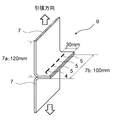
- first joint portion the J-shaped instead of the first joint portion, also produced in the same manner for welds employing the first junction of the length L 1 'is long straight, T-shaped A mold peeling test piece 9 was prepared.
- the T-shaped peeling test piece was subjected to a tensile test in which the length direction of the long side of the two L-shaped steel sheets was pulled in the tensile direction at a speed of 10 mm / min, and the peeling strength (maximum load) was measured. ..
- the peel strength was 3.0 kN or more was judged as "pass".
- Table 2 shows the results of determining the presence or absence of weld cracks and the results of measuring the peel strength. From this result, the test pieces (No. 1, 8, 15, 22, 29, 36, 43, 50, 57 and 64) that were laminated and laser beam welded under the conditions suitable for the present invention were all welded ends of the joints. No cracks were generated in the portion, and the peel strength was 3.0 kN or more. On the other hand, No. In the test pieces of 2, 9, 16, 23, 30, 37, 44, 51, 58 and 65, the gap G at the weld was larger than 15% of the total thickness T of the steel sheet, so all of them were welded ends at the joint. Cracks occurred in the portion, and the peel strength was less than 3.0 kN. In addition, No.
- the width w of the molten metal at the joint was larger than 1/2 of the minimum thickness b of the molten metal at the joint. Weld cracks occurred.
- the width w of the molten metal at the joint was smaller than 1/8 of the minimum thickness b of the molten metal at the joint. No welding cracks occurred, but the peel strength was less than 3.0 kN. In addition, No.
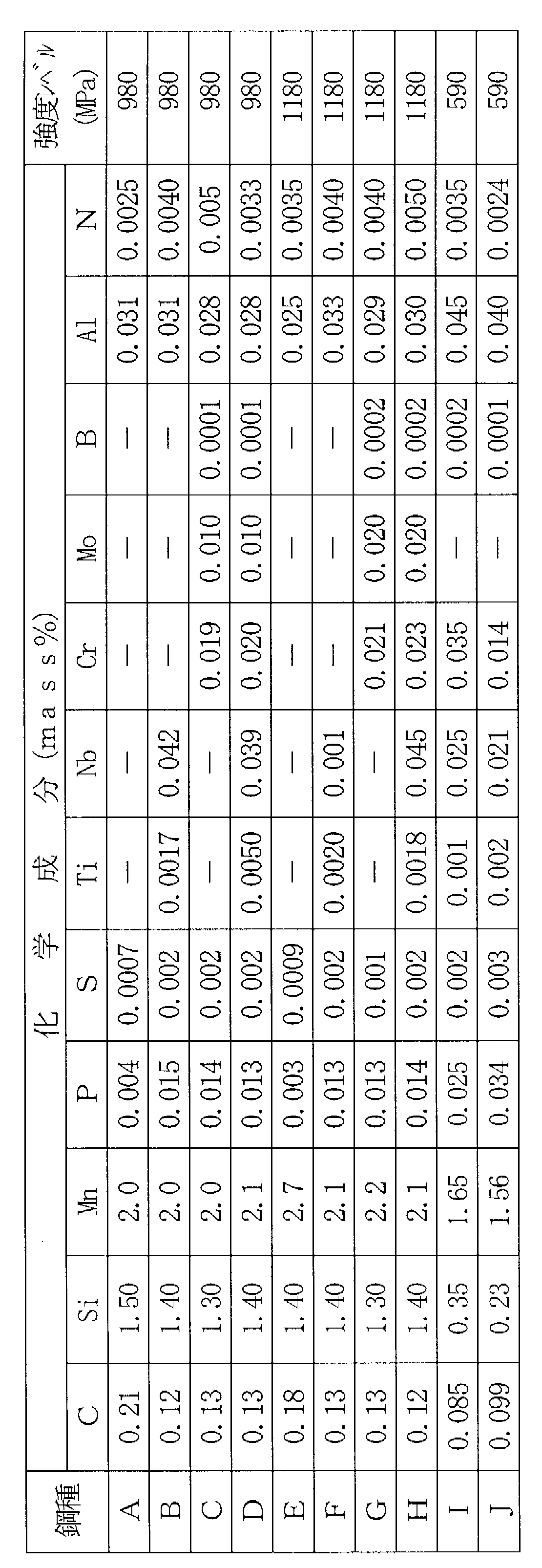
- Reference numerals 71 and 72 show the test results for a test piece obtained by laminating and laser beam welding two steel plates having different strength levels under conditions suitable for the present invention, and even in combination with the 590 MPa class and the 980 MPa class, No. 1 in which the composition of steel is within the preferable range of the present invention.
- No. 71 has no weld cracks and excellent peel strength can be obtained, but the composition of steel is outside the preferable range of the present invention.
- No. Reference numeral 73 denotes a test piece that employs a linear joint having a long length L1'as the first joint.
- the technique of the present invention enables high-speed and low-distortion welding, it can be preferably applied to a structural member for an automobile having a flange portion.
Landscapes
- Engineering & Computer Science (AREA)
- Physics & Mathematics (AREA)
- Optics & Photonics (AREA)
- Mechanical Engineering (AREA)
- Plasma & Fusion (AREA)
- Laser Beam Processing (AREA)
Abstract
Description
15.0≦L1≦30.0 ・・・(1)
8.0≦L2≦20.0 ・・・(2)
1/8≦w/b≦1/2 ・・・(3)
1/4≦a/(L1+L2)≦1/2または1/2≦a/L2≦1 ・・・(4)
ここで、L1:第1接合部の長さ(mm)
L2:後続接合部の長さ(mm)
b:接合部の溶融金属の最小厚(mm)
w:接合部の溶融金属の幅(mm)
a:接合部同士間の最短距離(mm)
のすべてを満たすことを特徴とする重ねレーザ溶接継手である。
30.0<L1´≦40.0 ・・・(1´)
ここで、L1´:直線状接合部の長さ(mm)
を満たすことを特徴とする。
・A群;Ti:0.0005~0.01mass%およびNb:0.005~0.050mass%のうちから選ばれる1種または2種
・B群;Cr:1.0mass%以下、Mo:0.50mass%以下およびB:0.10mass%以下のうちから選ばれる1種または2種以上
のうちの少なくとも1群の成分を含有することを特徴とする。
15.0≦L1≦30.0 ・・・(1)
8.0≦L2≦20.0 ・・・(2)
1/8≦w/b≦1/2 ・・・(3)
1/4≦a/(L1+L2)≦1/2または1/2≦a/L2≦1 ・・・(4)
ここで、L1:第1接合部の長さ(mm)
L2:後続接合部の長さ(mm)
b:接合部の溶融金属の最小厚(mm)
w:接合部の溶融金属の幅(mm)
a:接合部同士間の最短距離(mm)
のすべてを満たすよう、レーザ出力、焦点位置、溶接速度およびビーム径のうちの少なくとも1つを制御することを特徴とする重ねレーザ溶接継手の製造方法を提案する。
30.0<L1´≦40.0 ・・・(1´)
ここで、L1´:直線状接合部の長さ(mm)
を満たすようレーザ出力、焦点位置、溶接速度およびビーム径のうちの少なくとも1つを制御することを特徴とする。
<重ねレーザ溶接継手>
図1は、従来の重ねレーザ溶接継手の一例を示す斜視図である。重ねレーザ溶接継手1は、少なくとも2枚の鋼板を重ね合わせたものであり、図1に示した例では、縦壁部2aおよび縦壁部2aの先端から外側へ延びるフランジ部2bを有する断面形状が略ハット状の鋼板2と、平らなパネル状の鋼板3の2枚の鋼板が、フランジ部2bと鋼板3とが対向するように重ね合わせられて接合面を形成しており、フランジ部2bの上方からフランジ部2bの表面にレーザビームを照射し、少なくとも鋼板2を貫通する溶融部(溶融金属部)を形成し、凝固させて接合部(溶接点)を形成することで溶接が行われている。なお、上記溶融部の周辺には熱影響部(HAZ)が存在するが、本発明の接合部は、熱影響部を除いた溶融部のみのことをいう。
15.0≦L1≦30.0 ・・・(1)
8.0≦L2≦20.0 ・・・(2)
1/8≦w/b≦1/2 ・・・(3)
1/4≦a/(L1+L2)≦1/2または1/2≦a/L2≦1 ・・・(4)
ここで、L1:第1接合部の長さ(mm)
L2:後続接合部の長さ(mm)
b:接合部の溶融金属の最小厚(mm)
w:接合部の溶融金属の幅(mm)
a:接合部間同士間の最短距離(mm)
のすべてを満たしていることが必要であることがわかった。
以下、具体的に説明する。
本発明の重ねレーザビーム溶接継手は、溶接部を構成する鋼板の合計厚Tに対する溶接部を構成する鋼板間の合計間隙Gの比(G/T)が0~0.15、すなわち、溶接部を構成する鋼板の合計厚Tに対する溶接部を構成する鋼板間の合計間隙Gの比率が0~15%の範囲内にあることが必要である。上記GのTに対する比率が15%を超えると、溶接終端部のクレータの深さが深くなり、より応力が集中し易くなるからである。好ましくは0~10%の範囲である。
先述したように、本発明の重ねレーザ溶接継手は、溶接部を構成する第1接合部の溶接終端部の割れを防止するためには、第1接合部の形状を直線状接合部と円弧状または円状の曲線状接合部とからなるJ字状とすることが重要であるが、溶接終端部の割れをより確実に防止し、かつ、十分な強度の剥離強度を確保するためには、上記第1接合部の長さL1は、15.0~30.0mmの範囲とする必要がある。なお、J字状の第1接合部の長さL1は、図3に示したように、直線状接合部と曲線状接合部の合計長さである。L1が15.0mmより短いと、第1接合部の溶接終端部に割れが発生する。好ましくは20.0mm以上である。一方、L1の上限は、割れを防止する観点からの制限はないが、溶接時間を短縮する観点から、30.0mm以下とする。好ましくは25.0mm以下である。
また、本発明の重ねレーザ溶接継手は、溶接部を構成する後続接合部の長さL2を8.0~20.0mmの範囲とする必要がある。L2が8.0mmより短い場合、先行の接合部の溶接始端部と、後行の接合部の溶接終端部を対向させても、溶接終端部にかかる応力を緩和するだけの溶接面積を確保できないため、溶接終端部の割れを確実に防止できない。好ましくは10.0mm以上である。一方、L2の上限は、割れを防止する観点からの制限はないが、溶接時間を短縮する観点から、20.0mm以下とする。好ましくは15.0mm以下である。
また、本発明の重ねレーザ溶接継手は、溶接部を構成する接合部の溶接終端部(最終凝固部)に生じる最小厚bに対する接合部の溶融金属の幅wの比(w/b)が1/8~1/2の範囲であることが必要である。上記比(w/b)が1/2より大きいと、第1接合部や後続接合部の溶接終端部の最終凝固部にかかる溶融部外周部分から外側に向かう引張応力が大きくなり、溶接割れの発生を抑えることができない。一方、上記比(w/b)が1/8より小さいと、接合部の強度を十分に確保できない。すなわち、先行の接合部の溶接始端部と後行の接合部の溶接終端部とを対向させることに加えて、接合部における比(w/b)を1/8~1/2の範囲とすることで、接合部の溶接終端部における割れをより確実に防止し、かつ、溶接部の剥離強度を十分な強度とすることができる。好ましい比(w/b)は、1/6~1/3の範囲である。
また、本発明の重ねレーザ溶接継手は、接合部同士間の最短距離aは、第1接合部と隣接する後続接合部間の場合は、(第1接合部の長さL1+後続接合部長さのL2)に対する上記aの比(a/(L1+L2))が1/4~1/2の範囲、隣接する後続接合部同士間の場合は、後続接合部の長さL2に対する上記aの比(a/L2)が1/2~1の範囲であることが必要である。上記比(a/(L1+L2))が1/2より大きい場合、あるいは、上記比(a/L2)が1より大きい場合には、後続接合部はその接合部の先行接合部からの接合部周囲の鋼板変形を抑制する効果を十分に得ることができず、溶接終端部の割れを防止することができない。なお、上記aの下限値は、割れを防止する観点からの制限はないが、溶接時間を短縮する観点から、上記比(a/(L1+L2))は1/4以上、上記比(a/L2)は、1/2以上とする。なお、好ましい比(a/(L1+L2))は、1/3~2/5の範囲、好ましい比(a/L2)は、3/5~9/10の範囲である。
30.0<L1´≦40.0 ・・・(1´)
ここで、L1´:直線状接合部の長さ(mm)
を満たすことが必要である。第1接合部が直線状接合部のみからなる場合の長さL1´が30.0mm以下の場合、第1接合部の終端部に割れが発生する。好ましくは32.0mm以上である。一方、L1´の上限は、割れを防止する観点からの制限はないが、溶接時間を短縮する観点から、40.0mm以下とする。好ましくは38.0mm以下である。
なお、図1~4には、2枚の鋼板を重ねて重ねレーザ溶接継手を構成した例について示したが、3枚以上の鋼板を重ね合わせて溶接継手を構成してもよいことは勿論である。
本発明の重ねレーザ溶接継手を構成する鋼板は、それぞれの板厚が、自動車車体の外板や構造部材(強度部材)として一般的に用いられている0.5~3.2mmの範囲内のものであればよく、特に制限はない。また、複数の鋼板は、全て同じ板厚であってもよいし、個々に異なる板厚であってもよい。例えば、図4に示した形状の重ねレーザ溶接継手1の場合には、上側の鋼板2の板厚t2を0.6~1.8mm、下側の鋼板3の板厚t3を1.0~2.5mmの範囲としてもよいし、上側の鋼板2の板厚t2および下側の鋼板3の板厚t3を同じ0.5~3.2mmの板厚としてもよい。
また、本発明の重ねレーザ溶接継手を構成する複数の鋼板の成分組成は、特に制限しないが、少なくとも1つの鋼板は、以下に説明するように、C:0.07~0.4mass%、Si:0.2~3.5mass%、Mn:1.8~5.5mass%、P+S:0.03mass%以下、Al:0.08mass%以下およびN:0.010mass%以下を含有し、残部がFeおよび不可避不純物からなる成分組成を有するものであることが好ましい。
Cは、鋼の強度向上に有効な元素であり、0.07mass%以上含有させることによって、析出強化や変態強化の効果を得ることができる。また、C含有量を0.4mass%以下とすることで、粗大な炭化物の析出を招くことなく、所望の強度と加工性を確保することができる。そのため、C含有量は0.07~0.4mass%の範囲とするのが好ましい。より好ましくは0.15~0.3mass%の範囲である。
Siは、固溶強化能に優れる元素であり、0.2mass%以上含有させることで鋼の強度を高めることができる。また、Si含有量を3.5mass%以下とすることで、溶接熱影響部の過度の硬化を抑制し、溶接熱影響部の靱性および耐低温割れ性の劣化を防止することができる。そのため、Si含有量は0.2~3.5mass%の範囲とするのが好ましい。より好ましくは、1.0~2.5mass%の範囲である。
Mnは、焼入性を向上し、粗大な炭化物の析出を抑止するのに有効な元素であり、1.8mass%以上含有させることが好ましい。また、Mn含有量を5.5mass%以下とすることで、粒界脆化感受性の上昇を抑制し、靱性および耐低温割れ性の劣化を防止することができる。そのため、Mn含有量は1.8~5.5mass%の範囲とするのが好ましい。より好ましくは、2.0~3.5mass%の範囲である。
PおよびSは、鋼の延性や靭性に悪影響を及ぼす有害元素であり、PとSの合計含有量を0.03mass%以下とすることで、延性や靱性の低下を防止し、所望の強度と加工性を確保することができる。そのため、PとSの含有量は、合計で0.03mass%以下とするのが好ましい。より好ましくは0.02mass%以下である。
Alは、製鋼の段階で脱酸剤として添加される元素であり、0.01mass%以上添加されるのが一般的である。しかし、Al含有量が0.08mass%を超えると、アルミナなどの介在物が増大し、耐疲労特性への悪影響が顕在化するようになる。したがって、Al含有量は0.08mass%以下とする。好ましくは0.02~0.07mass%の範囲である。
Nは、鋼の耐時効性を大きく劣化させる元素であり、極力低減するのが好ましい。特に、Nが0.010mass%を超えると、耐時効性の劣化が顕著となるため、N含有量は0.010mass%以下とする。なお、Nの下限は特に限定しないが、製造コストの上昇を防止する観点から、0.001mass%程度とするのが好ましい。
TiおよびNbはいずれも、炭化物や窒化物を形成して析出し、鋼板製造時の焼鈍中におけるオーステナイトの粗大化を抑制する効果がある。上記効果を得るためには、TiおよびNbのうちから選ばれる1種または2種を、Tiは0.0005mass%以上、Nbは0.005mass%以上含有させることが好ましい。しかし、TiおよびNbを過剰に含有させても、上記効果が飽和し、原料コストの上昇を招くだけである。また、再結晶温度を上昇させるので、鋼板製造時の焼鈍後の金属組織が不均一となり、伸びフランジ性が損なわれる虞がある。さらに、炭化物または窒化物の析出量が増大して降伏比が上昇し、形状凍結性が劣化する虞もある。よって、Tiおよび/またはNbを含有させる場合には、Tiは0.01mass%以下、Nbは0.050mass%以下とするのが好ましい。より好ましい含有量は、Ti:0.0006~0.0080mass%、Nb:0.010~0.040mass%の範囲である。
Cr,MoおよびBは、鋼の焼入性を向上させるのに有効な元素であり、上記効果を得るためには、Cr:0.01mass%以上、Mo:0.004mass%以上およびB:0.0001mass%以上のうちの1種以上を含有させることが好ましい。しかし、これらの元素を過剰に含有させても、上記効果は飽和し、原料コストの上昇を招くだけである。よって、Cr,MoおよびBを含有させる場合には、Cr:1.0mass%以下、Mo:0.50mass%以下、B:0.10mass%以下として添加するのが好ましい。より好ましくは、Cr:0.02~0.50mass%、Mo:0.01~0.10mass%、B:0.001~0.03mass%の範囲である。
また、本発明の重ねレーザ溶接継手を構成する複数の鋼板のうち、少なくとも1つの鋼板は、引張強さTSが980MPa以上の高張力鋼板とすることが好ましい。少なくとも1つの鋼板が上記した高張力鋼板であれば、重ねレーザ溶接継手は、高い接合強度を得ることができるとともに、従来の溶接方法で溶接割れが発生する場合でも、本発明では、先行接合部による接合部周囲の鋼板変形を抑制する効果によって、溶接割れの発生を防止することができる。したがって、例えば、複数の鋼板のうち少なくとも1つの鋼板を、上記した成分組成を有し、かつ、引張強さTSが980MPa以上とするのが好ましい。なお、本発明の重ねレーザビーム溶接継手を構成する複数の鋼板は、同一の成分、同一の強度の鋼板であってもよいし、異なる成分、異なる強度の鋼板であってもよい。
次に、本発明の重ねレーザ溶接継手の製造方法について説明する。
図5は、本発明の重ねレーザ溶接継手の製造に用いる溶接方法の一例を説明する図である。本発明の重ねレーザ溶接継手1は、まず、複数の鋼板を上下に重ね合わせ、その重ね合わせた複数の鋼板のうち、最も上側の鋼板表面にレーザビームを断続的に照射して第1接合部4と、それに続く複数の後続接合部5を順次形成することにより溶接部を形成して製造する。
なお、片側溶接においては、溶接時の溶落ちを防止する観点からは、重ね合わせた複数の鋼板のうち、板厚が大きい方の鋼板側からレーザビームを照射するのが好ましい。一方、未貫通による未接合を防止する観点からは、板厚が薄い方からレーザビームを照射するのが好ましい。なお、鋼板の板厚が同一の場合には、いずれの鋼板側からレーザビームを照射してもよい。
15.0≦L1≦30.0 ・・・(1)
8.0≦L2≦20.0 ・・・(2)
1/8≦w/b≦1/2 ・・・(3)
1/4≦a/(L1+L2)≦1/2または1/2≦a/L2≦1 ・・・(4)
ここで、L1:第1接合部の長さ(mm)
L2:後続接合部の長さ(mm)
b:接合部の溶融金属の最小厚(mm)
w:接合部の溶融金属の幅(mm)
a:接合部同士間の最短距離(mm)
のすべてを満たすように、レーザビームの溶接条件、具体的には、レーザ出力、焦点位置、溶接速度およびビーム径のうちの少なくとも1つを制御することが重要である。
30.0≦L1´≦40.0 ・・・(1´)
ここで、L1´:直線状接合部の長さ(mm)
を満たすように制御することが重要である。これにより、J字状でなくとも、第1接合部の溶接終端部に発生する割れを防止することができる。
次に、本発明の自動車車体用構造部材について説明する。
本発明の重ねレーザ溶接継手を好ましく用いることができる例として、自動車車体の骨格部分となる構造部材(強度部材)がある。前述した図1(図4)に示した部材は、断面形状が略ハット形状のフレーム部品である鋼板2と、パネル部品の鋼板3とから構成され、鋼板2のフランジ部2bと、このフランジ部2bに対向して配置された鋼板3とが、上記したレーザビーム溶接によって形成された第1接合部4と後続接合部5からなる溶接部により接合されて、閉断面を構成している。このような形状を有する部材を自動車車体の強度部材に適用するためには、衝突安全性を確保する観点から、溶接部の強度に優れていることが重要であるが、本発明の重ねレーザ溶接継手は、接合部の溶接終端部に割れがなく、かつ、十分な剥離強度を有するので、例えば、自動車車体のセンターピラーやルーフレールなどの構造部材に好適に用いることができる。
5t≦X≦8t ・・・(5)
ここで、t:溶接部を構成する鋼板の中で最も厚い鋼板の板厚(mm)
を満たすことが好ましい。例えば、最も厚い鋼板の板厚tが2mmであった場合、溶接位置Xは10~16mmの範囲とするのが好ましいことになる。
次いで、上記T字型の剥離試験片について、2枚のL字型鋼板の長辺の長さ方向を引張方向する引張試験を、速度10mm/minで行い、剥離強度(最大荷重)を測定した。なお、本実施例では、剥離強度が3.0kN以上の場合を「合格」と判定した。
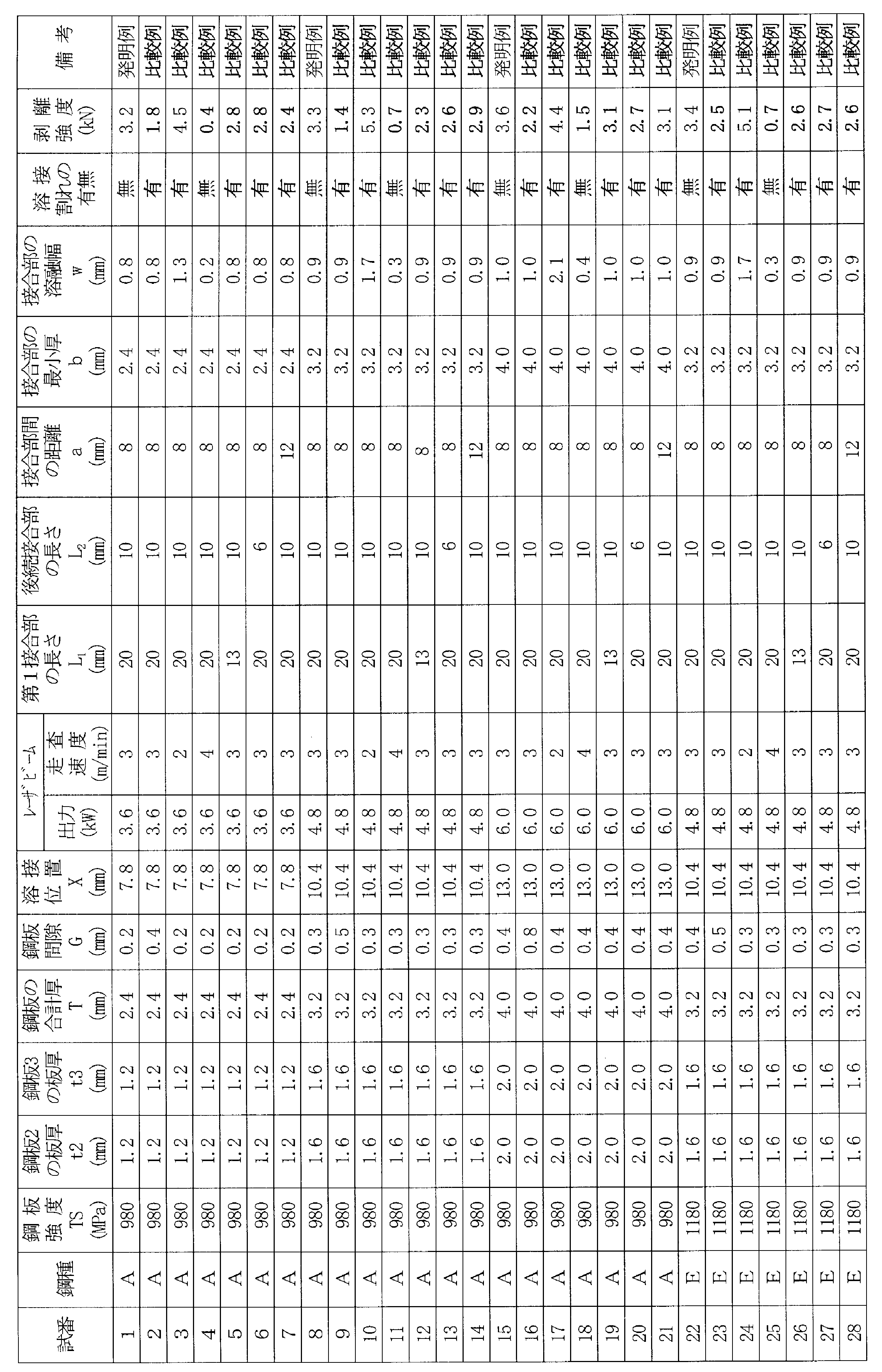
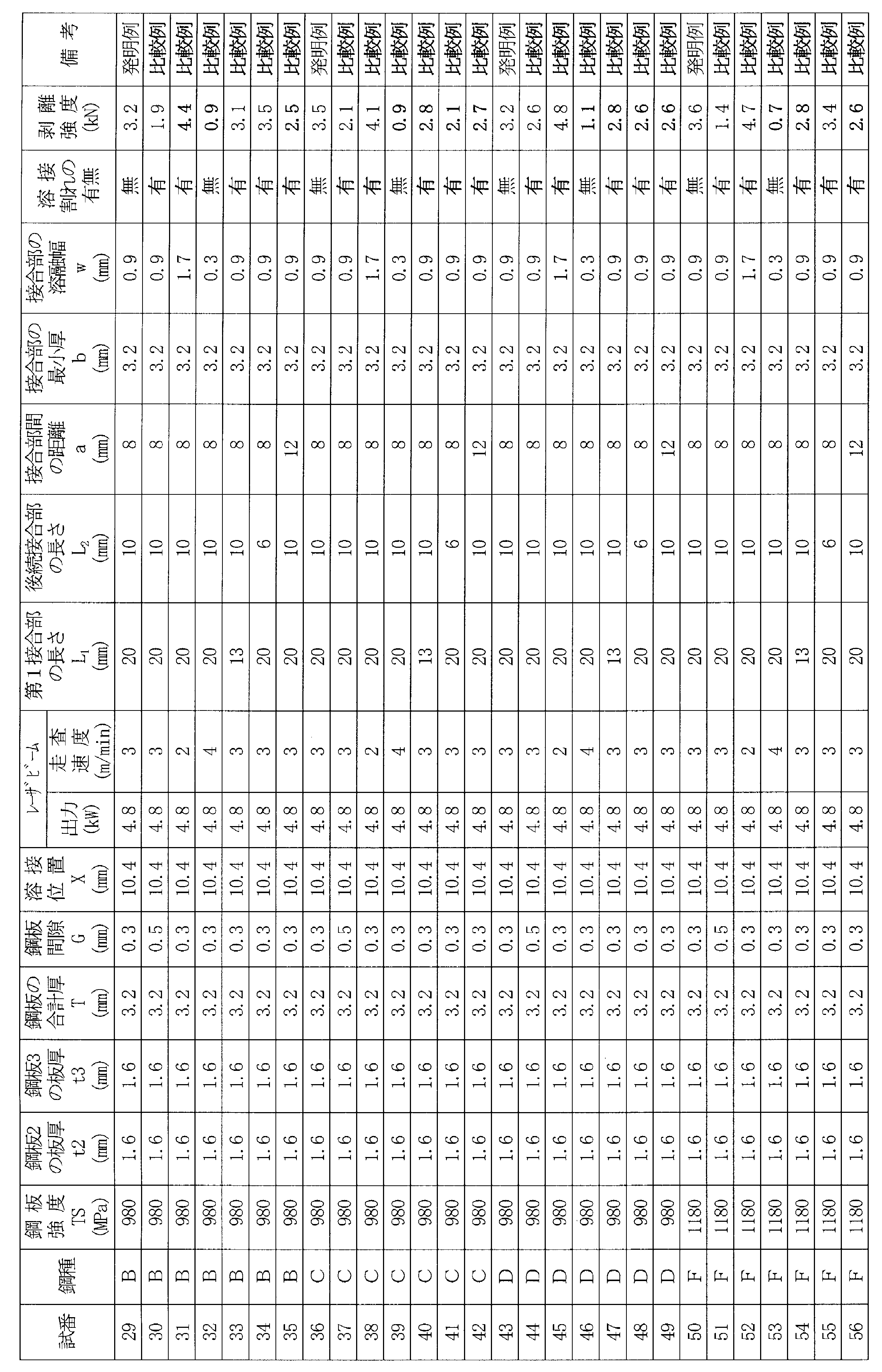

この結果から、本発明に適合する条件で重ねレーザビーム溶接した試験片(No.1,8,15,22,29,36,43,50,57および64)は、いずれも接合部の溶接終端部に割れの発生がなく、剥離強度も3.0kN以上であった。
これに対して、No.2,9,16,23,30,37,44,51,58および65の試験片は、溶接部の間隙Gが、鋼板の合計厚Tの15%より大きかったため、いずれも接合部の溶接終端部に割れが発生し、剥離強度も3.0kN未満であった。
また、No.3,10,17,24,31,38,45,52,59および66の試験片は、接合部の溶融金属の幅wが接合部の溶融金属の最小厚bの1/2より大きかったため、溶接割れが発生した。一方、No.4,11,18,25,32,39,46,53,60および67の試験片は、接合部の溶融金属の幅wが接合部の溶融金属の最小厚bの1/8より小さかったため、溶接割れの発生はなかったが、剥離強度が3.0kN未満であった。
また、No.5,12,19,26,33,40,47,54,61および68の試験片は、第1接合部の長さL1が15.0mmより短いため、溶接割れが発生した。
また、No.6,13,20,27,34,41,48,55,62および69の試験片は、後続接合部の長さL2が8.0mmより短いため、溶接割れが発生した。
また、No.7,14,21,28,35,42,49,56,63および70の試験片は、第1接合部と隣接する後続接合部間および後続接合部同士間の距離aが、後続接合部長さのL2より長いため、溶接割れが発生し、剥離強度も3.0kN未満であった。
また、No.71および72は、強度レベルが異なる2枚の鋼板を、本発明に適合する条件で重ねレーザビーム溶接した試験片についての試験結果を示した結果であり、590MPa級と980MPa級との組み合わせでも、鋼の成分組成が本発明の好適範囲内であるNo.71は、溶接割れもなく、優れた剥離強度が得られるが、鋼の成分組成が本発明の好適範囲外であるNo.72は、溶接割れが発生し、剥離強度も3.0kN未満であった。
また、No.73は、第1接合部として長さL1´が長い直線状の接合部を採用した試験片であり、本発明に適合する条件で重ねレーザビーム溶接することで、溶接割れもなく、J字状の第1接合部と同等の剥離強度が得られることがわかった。
上記したように、本発明に従い重ねレーザビーム溶接を行った本発明例では、いずれも本発明が目的とする特性を有する良好な重ねレーザビーム溶接継手が得られているのに対し、本発明の条件を外れる比較例では、良好な重ねレーザビーム溶接継手を得ることができなかった。
2、3:鋼板
2a:縦壁部
2b:フランジ部
4、14:第1接合部
4a、14a:第1接合部の溶接終端部の中心部
5、15:後続接合部
5a、15a:後続接合部の溶接終端部の中心部
6:溶接部
7:L字鋼板
7a:L字鋼板の長辺
7b:L字鋼板の幅
8:接合部の溶接終端部の割れ
9:剥離試験片
WH:溶接ヘッド
LB:レーザビーム
D:溶接ヘッドの移動方向
d:レーザビームの走査方向
L1、L1´:第1接合部の長さ
L2:後続接合部の長さ
a:隣接する接合部同士間の最短距離
b:接合部の溶融金属の最小厚
w:接合部の溶融金属の幅
G:鋼板間の間隙
S:接合部の溶接始端部
E:接合部の溶接終端部
Fa:従来の接合部の溶接終端部にかかる応力
Fb:後続接合部の初期溶接終端部にかかる応力
Fc:第1接合部の溶接終端部にかかる応力
0:溶接位置Xの基準点
Claims (8)
- 複数の鋼板を重ねてなる溶接部を有する重ねレーザ溶接継手において、
上記溶接部を構成する鋼板間の合計間隙Gが、溶接部を構成する鋼板の合計厚Tの0~15%の範囲内にあり、
上記溶接部が、線状の第1接合部と、その第1接合部に続いて列状に配列した直線状の後続接合部とからなり、
上記第1接合部の溶接始端部と、それに隣接する後続接合部の溶接終端部とが対向し、かつ、上記後続接合部同士の溶接始端部と溶接終端部とが対向してなるとともに、
上記第1接合部が、直線状接合部と、その直線状接合部の溶接終端部側に接続した円弧状または円状の曲線状接合部とからなるJ字形状を有し、
さらに、上記溶接部は、下記(1)~(4)式のすべてを満たすことを特徴とする重ねレーザ溶接継手。
記
15.0≦L1≦30.0 ・・・(1)
8.0≦L2≦20.0 ・・・(2)
1/8≦w/b≦1/2 ・・・(3)
1/4≦a/(L1+L2)≦1/2または1/2≦a/L2≦1 ・・・(4)
ここで、L1:第1接合部の長さ(mm)
L2:後続接合部の長さ(mm)
b:接合部の溶融金属の最小厚(mm)
w:接合部の溶融金属の幅(mm)
a:接合部同士間の最短距離(mm) - 上記第1接合部が、直線状接合部のみからなり、上記(1)式に代えて、下記(1´)式を満たすことを特徴とする請求項1に記載の重ねレーザ溶接継手。
記
30.0<L1´≦40.0 ・・・(1´)
ここで、L1´:直線状接合部の長さ(mm) - 上記鋼板のうちの少なくとも1つが、C:0.07~0.4mass%、Si:0.2~3.5mass%、Mn:1.8~5.5mass%、P+S:0.03mass%以下、Al:0.08mass%以下およびN:0.010mass%以下を含有し、残部がFeおよび不可避的不純物からなる成分組成を有することを特徴とする請求項1または2に記載の重ねレーザビーム溶接継手。
- 上記鋼板は、上記成分組成に加えてさらに、以下のA群およびB群のうちの少なくとも1群の成分を含有することを特徴とする請求項3に記載の重ねレーザ溶接継手。
記
・A群;Ti:0.0005~0.01mass%およびNb:0.005~0.050mass%のうちから選ばれる1種または2種
・B群;Cr:1.0mass%以下、Mo:0.50mass%以下およびB:0.10mass%以下のうちから選ばれる1種または2種以上 - 上記鋼板のうちの少なくとも1つが、引張強さが980MPa以上の高張力鋼板であることを特徴とする請求項1~4のいずれか1項に記載の重ねレーザ溶接継手。
- 複数の鋼板を上下に重ね合わせ、該重ね合わせた鋼板の片側表面にレーザビームを断続的に照射して、線状の第1接合部とその第1接合部に続いて直線状の後続接合部とが列状に配列した溶接部を形成する際、
上記溶接部を構成する鋼板間の合計間隙Gを、溶接部を構成する鋼板の合計厚Tの0~15%の範囲内とし、
上記レーザビームを照射する溶接ヘッドの移動方向とレーザビームの走査方向を逆向きとすることにより、第1接合部の溶接始端部と該第1接合部に隣接した後続接合部の溶接終端部とが対向し、かつ、上記後続接合部同士の溶接始端部と溶接終端部とが対向するようにするとともに、
上記第1接合部の形状を、直線状接合部と、その直線状接合部の溶接終端部側に接続した円弧状または円状の曲線状接合部とからなるJ字状とし、
さらに、上記溶接部が、下記式(1)~(4)式のすべてを満たすよう、レーザ出力、焦点位置、溶接速度およびビーム径のうちの少なくとも1つを制御することを特徴とする重ねレーザ溶接継手の製造方法。
記
15.0≦L1≦30.0 ・・・(1)
8.0≦L2≦20.0 ・・・(2)
1/8≦w/b≦1/2 ・・・(3)
1/4≦a/(L1+L2)≦1/2または1/2≦a/L2≦1 ・・・(4)
ここで、L1:第1接合部の長さ(mm)
L2:後続接合部の長さ(mm)
b:接合部の溶融金属の最小厚(mm)
w:接合部の溶融金属の幅(mm)
a:接合部同士間の最短距離(mm) - 上記第1接合部を、直線状接合部のみからなり、かつ、上記(1)式に代えて、下記(1´)式を満たすようレーザ出力、焦点位置、溶接速度およびビーム径のうちの少なくとも1つを制御することを特徴とする請求項6に記載の重ねレーザ溶接継手の製造方法。
記
30.0<L1´≦40.0 ・・・(1´)
ここで、L1´:直線状接合部の長さ(mm) - 請求項1~5のいずれか1項に記載の重ねレーザ溶接継手を有する自動車車体用構造部材。
Priority Applications (4)
| Application Number | Priority Date | Filing Date | Title |
|---|---|---|---|
| CN201980094061.XA CN113573838B (zh) | 2019-03-28 | 2019-03-28 | 搭接激光焊接接头及其制造方法以及汽车车身用结构部件 |
| JP2019533250A JP6583657B1 (ja) | 2019-03-28 | 2019-03-28 | 重ねレーザ溶接継手とその製造方法および自動車車体用構造部材 |
| KR1020217027195A KR102603852B1 (ko) | 2019-03-28 | 2019-03-28 | 겹침 레이저 용접 이음매와 그 제조 방법 및 자동차 차체용 구조 부재 |
| PCT/JP2019/013632 WO2020194669A1 (ja) | 2019-03-28 | 2019-03-28 | 重ねレーザ溶接継手とその製造方法および自動車車体用構造部材 |
Applications Claiming Priority (1)
| Application Number | Priority Date | Filing Date | Title |
|---|---|---|---|
| PCT/JP2019/013632 WO2020194669A1 (ja) | 2019-03-28 | 2019-03-28 | 重ねレーザ溶接継手とその製造方法および自動車車体用構造部材 |
Publications (1)
| Publication Number | Publication Date |
|---|---|
| WO2020194669A1 true WO2020194669A1 (ja) | 2020-10-01 |
Family
ID=68095259
Family Applications (1)
| Application Number | Title | Priority Date | Filing Date |
|---|---|---|---|
| PCT/JP2019/013632 Ceased WO2020194669A1 (ja) | 2019-03-28 | 2019-03-28 | 重ねレーザ溶接継手とその製造方法および自動車車体用構造部材 |
Country Status (4)
| Country | Link |
|---|---|
| JP (1) | JP6583657B1 (ja) |
| KR (1) | KR102603852B1 (ja) |
| CN (1) | CN113573838B (ja) |
| WO (1) | WO2020194669A1 (ja) |
Cited By (1)
| Publication number | Priority date | Publication date | Assignee | Title |
|---|---|---|---|---|
| CN113199146A (zh) * | 2021-03-24 | 2021-08-03 | 中车青岛四方机车车辆股份有限公司 | 侧墙焊接方法及装置、侧墙、车体、轨道车辆 |
Citations (5)
| Publication number | Priority date | Publication date | Assignee | Title |
|---|---|---|---|---|
| JPS5992189A (ja) * | 1982-11-18 | 1984-05-28 | Toshiba Corp | 鋼板枠の製造方法 |
| DE19627913A1 (de) * | 1995-08-05 | 1997-02-06 | Volkswagen Ag | Strahlgeschweißtes Karosseriebauteil zur Aufnahme einer Crash-Belastung |
| US20140333095A1 (en) * | 2009-04-03 | 2014-11-13 | GM Global Technology Operations LLC | Method for producing a body part of a vehicle and body part of a vehicle |
| JP2017030647A (ja) * | 2015-08-05 | 2017-02-09 | Jfeスチール株式会社 | 自動車用骨格部品および自動車用骨格部品の製造方法 |
| WO2018061526A1 (ja) * | 2016-09-29 | 2018-04-05 | Jfeスチール株式会社 | レーザ溶接継手の製造方法、レーザ溶接継手および自動車用骨格部品 |
Family Cites Families (18)
| Publication number | Priority date | Publication date | Assignee | Title |
|---|---|---|---|---|
| JP3763525B2 (ja) * | 2002-03-29 | 2006-04-05 | 本田技研工業株式会社 | 溶接方法および溶接装置 |
| JP4841970B2 (ja) | 2006-02-28 | 2011-12-21 | 新日本製鐵株式会社 | 重ねレーザ溶接方法 |
| JP2008207190A (ja) * | 2007-02-23 | 2008-09-11 | Nippon Sharyo Seizo Kaisha Ltd | 接合継手及び当該継手による鉄道車両 |
| JP2008296236A (ja) | 2007-05-30 | 2008-12-11 | Toyota Motor Corp | 重ねレーザ溶接方法 |
| JP2012125829A (ja) * | 2010-12-17 | 2012-07-05 | Panasonic Corp | レーザ接合方法および接合部品 |
| JP5630373B2 (ja) | 2011-05-19 | 2014-11-26 | 新日鐵住金株式会社 | 耐遅れ破壊特性に優れた鋼板溶接部の製造方法およびその溶接部を有する鋼構造物 |
| JP5505369B2 (ja) | 2011-05-19 | 2014-05-28 | 新日鐵住金株式会社 | 継手強度に優れたレーザ溶接継手及びその製造方法 |
| DE102012104362B4 (de) * | 2012-02-20 | 2014-07-24 | Scansonic Mi Gmbh | Verfahren zum Steppnahtschweißen einer stirnseitigen Flanschverbindung |
| AU2013222069A1 (en) * | 2012-02-26 | 2014-10-16 | Solexel, Inc. | Systems and methods for laser splitting and device layer transfer |
| DE202012102318U1 (de) * | 2012-06-22 | 2012-07-12 | Stiwa Holding Gmbh | Fügeverbindung zwischen metallischen Bauteilen und Schweißvorrichtung |
| KR101710851B1 (ko) * | 2012-08-08 | 2017-02-27 | 신닛테츠스미킨 카부시키카이샤 | 중첩부의 용접 방법 및 겹침 용접 부재 |
| EP3112077B1 (en) * | 2014-02-25 | 2021-03-31 | Panasonic Intellectual Property Management Co., Ltd. | Laser welding method |
| RU2682193C2 (ru) * | 2014-09-19 | 2019-03-15 | Ниппон Стил Энд Сумитомо Метал Корпорейшн | Сварное соединение, полученное при помощи лазерной сварки, и способ лазерной сварки |
| CN104759776B (zh) * | 2015-04-16 | 2017-01-11 | 上海振华重工集团(南通)有限公司 | 一种改进的轮胎吊轨道焊接工艺 |
| JP6443319B2 (ja) | 2015-12-24 | 2018-12-26 | Jfeスチール株式会社 | 重ねレーザスポット溶接継手および該溶接継手の製造方法 |
| CN108778608B (zh) * | 2016-03-15 | 2020-11-17 | 杰富意钢铁株式会社 | 搭接激光焊接接头、该焊接接头的制造方法以及汽车用骨架部件 |
| JP2018001197A (ja) | 2016-06-29 | 2018-01-11 | 株式会社神戸製鋼所 | レーザ溶接継手およびレーザ溶接継手の製造方法 |
| CN108857127B (zh) * | 2018-08-09 | 2021-01-22 | 北京长城华冠汽车科技股份有限公司 | 框架式铝合金车身顶盖的焊接方法 |
-
2019
- 2019-03-28 CN CN201980094061.XA patent/CN113573838B/zh active Active
- 2019-03-28 WO PCT/JP2019/013632 patent/WO2020194669A1/ja not_active Ceased
- 2019-03-28 JP JP2019533250A patent/JP6583657B1/ja active Active
- 2019-03-28 KR KR1020217027195A patent/KR102603852B1/ko active Active
Patent Citations (5)
| Publication number | Priority date | Publication date | Assignee | Title |
|---|---|---|---|---|
| JPS5992189A (ja) * | 1982-11-18 | 1984-05-28 | Toshiba Corp | 鋼板枠の製造方法 |
| DE19627913A1 (de) * | 1995-08-05 | 1997-02-06 | Volkswagen Ag | Strahlgeschweißtes Karosseriebauteil zur Aufnahme einer Crash-Belastung |
| US20140333095A1 (en) * | 2009-04-03 | 2014-11-13 | GM Global Technology Operations LLC | Method for producing a body part of a vehicle and body part of a vehicle |
| JP2017030647A (ja) * | 2015-08-05 | 2017-02-09 | Jfeスチール株式会社 | 自動車用骨格部品および自動車用骨格部品の製造方法 |
| WO2018061526A1 (ja) * | 2016-09-29 | 2018-04-05 | Jfeスチール株式会社 | レーザ溶接継手の製造方法、レーザ溶接継手および自動車用骨格部品 |
Cited By (1)
| Publication number | Priority date | Publication date | Assignee | Title |
|---|---|---|---|---|
| CN113199146A (zh) * | 2021-03-24 | 2021-08-03 | 中车青岛四方机车车辆股份有限公司 | 侧墙焊接方法及装置、侧墙、车体、轨道车辆 |
Also Published As
| Publication number | Publication date |
|---|---|
| KR102603852B1 (ko) | 2023-11-17 |
| JPWO2020194669A1 (ja) | 2021-04-30 |
| KR20210116648A (ko) | 2021-09-27 |
| CN113573838A (zh) | 2021-10-29 |
| CN113573838B (zh) | 2023-06-02 |
| JP6583657B1 (ja) | 2019-10-02 |
Similar Documents
| Publication | Publication Date | Title |
|---|---|---|
| JP6176428B1 (ja) | 重ねレーザ溶接継手、該溶接継手の製造方法および自動車用骨格部品 | |
| CN109641321B (zh) | 激光焊接接头的制造方法及激光焊接接头 | |
| CN112135706B (zh) | 搭接激光焊接接头、搭接激光焊接接头的制造方法和汽车用骨架部件 | |
| JP6443319B2 (ja) | 重ねレーザスポット溶接継手および該溶接継手の製造方法 | |
| JP7211491B2 (ja) | 重ねレーザスポット溶接継手とその製造方法および自動車車体用構造部材 | |
| JP6583657B1 (ja) | 重ねレーザ溶接継手とその製造方法および自動車車体用構造部材 | |
| JP6852797B2 (ja) | 重ねレーザ溶接継手、重ねレーザ溶接継手の製造方法および自動車用骨格部品 | |
| JP4374104B2 (ja) | 超微細鋼からなる、脆性き裂伝播停止特性に優れた継手及び構造体 | |
| JP7758258B1 (ja) | レーザ溶接継手およびその製造方法 |
Legal Events
| Date | Code | Title | Description |
|---|---|---|---|
| ENP | Entry into the national phase |
Ref document number: 2019533250 Country of ref document: JP Kind code of ref document: A |
|
| 121 | Ep: the epo has been informed by wipo that ep was designated in this application |
Ref document number: 19921174 Country of ref document: EP Kind code of ref document: A1 |
|
| ENP | Entry into the national phase |
Ref document number: 20217027195 Country of ref document: KR Kind code of ref document: A |
|
| NENP | Non-entry into the national phase |
Ref country code: DE |
|
| 122 | Ep: pct application non-entry in european phase |
Ref document number: 19921174 Country of ref document: EP Kind code of ref document: A1 |