WO2020194621A1 - 電動車両の制御装置及び電動車両の制御方法 - Google Patents
電動車両の制御装置及び電動車両の制御方法 Download PDFInfo
- Publication number
- WO2020194621A1 WO2020194621A1 PCT/JP2019/013434 JP2019013434W WO2020194621A1 WO 2020194621 A1 WO2020194621 A1 WO 2020194621A1 JP 2019013434 W JP2019013434 W JP 2019013434W WO 2020194621 A1 WO2020194621 A1 WO 2020194621A1
- Authority
- WO
- WIPO (PCT)
- Prior art keywords
- electric vehicle
- vehicle
- torque
- total mass
- motor
- Prior art date
- Legal status (The legal status is an assumption and is not a legal conclusion. Google has not performed a legal analysis and makes no representation as to the accuracy of the status listed.)
- Ceased
Links
Images


Classifications
-
- B—PERFORMING OPERATIONS; TRANSPORTING
- B60—VEHICLES IN GENERAL
- B60L—PROPULSION OF ELECTRICALLY-PROPELLED VEHICLES; SUPPLYING ELECTRIC POWER FOR AUXILIARY EQUIPMENT OF ELECTRICALLY-PROPELLED VEHICLES; ELECTRODYNAMIC BRAKE SYSTEMS FOR VEHICLES IN GENERAL; MAGNETIC SUSPENSION OR LEVITATION FOR VEHICLES; MONITORING OPERATING VARIABLES OF ELECTRICALLY-PROPELLED VEHICLES; ELECTRIC SAFETY DEVICES FOR ELECTRICALLY-PROPELLED VEHICLES
- B60L15/00—Methods, circuits, or devices for controlling the traction-motor speed of electrically-propelled vehicles
- B60L15/20—Methods, circuits, or devices for controlling the traction-motor speed of electrically-propelled vehicles for control of the vehicle or its driving motor to achieve a desired performance, e.g. speed, torque, programmed variation of speed
-
- B—PERFORMING OPERATIONS; TRANSPORTING
- B60—VEHICLES IN GENERAL
- B60L—PROPULSION OF ELECTRICALLY-PROPELLED VEHICLES; SUPPLYING ELECTRIC POWER FOR AUXILIARY EQUIPMENT OF ELECTRICALLY-PROPELLED VEHICLES; ELECTRODYNAMIC BRAKE SYSTEMS FOR VEHICLES IN GENERAL; MAGNETIC SUSPENSION OR LEVITATION FOR VEHICLES; MONITORING OPERATING VARIABLES OF ELECTRICALLY-PROPELLED VEHICLES; ELECTRIC SAFETY DEVICES FOR ELECTRICALLY-PROPELLED VEHICLES
- B60L2200/00—Type of vehicles
- B60L2200/28—Trailers
-
- B—PERFORMING OPERATIONS; TRANSPORTING
- B60—VEHICLES IN GENERAL
- B60L—PROPULSION OF ELECTRICALLY-PROPELLED VEHICLES; SUPPLYING ELECTRIC POWER FOR AUXILIARY EQUIPMENT OF ELECTRICALLY-PROPELLED VEHICLES; ELECTRODYNAMIC BRAKE SYSTEMS FOR VEHICLES IN GENERAL; MAGNETIC SUSPENSION OR LEVITATION FOR VEHICLES; MONITORING OPERATING VARIABLES OF ELECTRICALLY-PROPELLED VEHICLES; ELECTRIC SAFETY DEVICES FOR ELECTRICALLY-PROPELLED VEHICLES
- B60L2240/00—Control parameters of input or output; Target parameters
- B60L2240/10—Vehicle control parameters
- B60L2240/12—Speed
-
- B—PERFORMING OPERATIONS; TRANSPORTING
- B60—VEHICLES IN GENERAL
- B60L—PROPULSION OF ELECTRICALLY-PROPELLED VEHICLES; SUPPLYING ELECTRIC POWER FOR AUXILIARY EQUIPMENT OF ELECTRICALLY-PROPELLED VEHICLES; ELECTRODYNAMIC BRAKE SYSTEMS FOR VEHICLES IN GENERAL; MAGNETIC SUSPENSION OR LEVITATION FOR VEHICLES; MONITORING OPERATING VARIABLES OF ELECTRICALLY-PROPELLED VEHICLES; ELECTRIC SAFETY DEVICES FOR ELECTRICALLY-PROPELLED VEHICLES
- B60L2240/00—Control parameters of input or output; Target parameters
- B60L2240/10—Vehicle control parameters
- B60L2240/14—Acceleration
- B60L2240/16—Acceleration longitudinal
-
- B—PERFORMING OPERATIONS; TRANSPORTING
- B60—VEHICLES IN GENERAL
- B60L—PROPULSION OF ELECTRICALLY-PROPELLED VEHICLES; SUPPLYING ELECTRIC POWER FOR AUXILIARY EQUIPMENT OF ELECTRICALLY-PROPELLED VEHICLES; ELECTRODYNAMIC BRAKE SYSTEMS FOR VEHICLES IN GENERAL; MAGNETIC SUSPENSION OR LEVITATION FOR VEHICLES; MONITORING OPERATING VARIABLES OF ELECTRICALLY-PROPELLED VEHICLES; ELECTRIC SAFETY DEVICES FOR ELECTRICALLY-PROPELLED VEHICLES
- B60L2240/00—Control parameters of input or output; Target parameters
- B60L2240/10—Vehicle control parameters
- B60L2240/26—Vehicle weight
-
- B—PERFORMING OPERATIONS; TRANSPORTING
- B60—VEHICLES IN GENERAL
- B60L—PROPULSION OF ELECTRICALLY-PROPELLED VEHICLES; SUPPLYING ELECTRIC POWER FOR AUXILIARY EQUIPMENT OF ELECTRICALLY-PROPELLED VEHICLES; ELECTRODYNAMIC BRAKE SYSTEMS FOR VEHICLES IN GENERAL; MAGNETIC SUSPENSION OR LEVITATION FOR VEHICLES; MONITORING OPERATING VARIABLES OF ELECTRICALLY-PROPELLED VEHICLES; ELECTRIC SAFETY DEVICES FOR ELECTRICALLY-PROPELLED VEHICLES
- B60L2240/00—Control parameters of input or output; Target parameters
- B60L2240/40—Drive Train control parameters
- B60L2240/42—Drive Train control parameters related to electric machines
- B60L2240/423—Torque
-
- B—PERFORMING OPERATIONS; TRANSPORTING
- B60—VEHICLES IN GENERAL
- B60L—PROPULSION OF ELECTRICALLY-PROPELLED VEHICLES; SUPPLYING ELECTRIC POWER FOR AUXILIARY EQUIPMENT OF ELECTRICALLY-PROPELLED VEHICLES; ELECTRODYNAMIC BRAKE SYSTEMS FOR VEHICLES IN GENERAL; MAGNETIC SUSPENSION OR LEVITATION FOR VEHICLES; MONITORING OPERATING VARIABLES OF ELECTRICALLY-PROPELLED VEHICLES; ELECTRIC SAFETY DEVICES FOR ELECTRICALLY-PROPELLED VEHICLES
- B60L2240/00—Control parameters of input or output; Target parameters
- B60L2240/40—Drive Train control parameters
- B60L2240/46—Drive Train control parameters related to wheels
-
- B—PERFORMING OPERATIONS; TRANSPORTING
- B60—VEHICLES IN GENERAL
- B60L—PROPULSION OF ELECTRICALLY-PROPELLED VEHICLES; SUPPLYING ELECTRIC POWER FOR AUXILIARY EQUIPMENT OF ELECTRICALLY-PROPELLED VEHICLES; ELECTRODYNAMIC BRAKE SYSTEMS FOR VEHICLES IN GENERAL; MAGNETIC SUSPENSION OR LEVITATION FOR VEHICLES; MONITORING OPERATING VARIABLES OF ELECTRICALLY-PROPELLED VEHICLES; ELECTRIC SAFETY DEVICES FOR ELECTRICALLY-PROPELLED VEHICLES
- B60L2250/00—Driver interactions
- B60L2250/24—Driver interactions by lever actuation
-
- B—PERFORMING OPERATIONS; TRANSPORTING
- B60—VEHICLES IN GENERAL
- B60L—PROPULSION OF ELECTRICALLY-PROPELLED VEHICLES; SUPPLYING ELECTRIC POWER FOR AUXILIARY EQUIPMENT OF ELECTRICALLY-PROPELLED VEHICLES; ELECTRODYNAMIC BRAKE SYSTEMS FOR VEHICLES IN GENERAL; MAGNETIC SUSPENSION OR LEVITATION FOR VEHICLES; MONITORING OPERATING VARIABLES OF ELECTRICALLY-PROPELLED VEHICLES; ELECTRIC SAFETY DEVICES FOR ELECTRICALLY-PROPELLED VEHICLES
- B60L2250/00—Driver interactions
- B60L2250/26—Driver interactions by pedal actuation
- B60L2250/28—Accelerator pedal thresholds
-
- Y—GENERAL TAGGING OF NEW TECHNOLOGICAL DEVELOPMENTS; GENERAL TAGGING OF CROSS-SECTIONAL TECHNOLOGIES SPANNING OVER SEVERAL SECTIONS OF THE IPC; TECHNICAL SUBJECTS COVERED BY FORMER USPC CROSS-REFERENCE ART COLLECTIONS [XRACs] AND DIGESTS
- Y02—TECHNOLOGIES OR APPLICATIONS FOR MITIGATION OR ADAPTATION AGAINST CLIMATE CHANGE
- Y02T—CLIMATE CHANGE MITIGATION TECHNOLOGIES RELATED TO TRANSPORTATION
- Y02T10/00—Road transport of goods or passengers
- Y02T10/60—Other road transportation technologies with climate change mitigation effect
- Y02T10/72—Electric energy management in electromobility
Definitions
- the present invention relates to an electric vehicle control device and an electric vehicle control method.
- JP2017-139230 when the accelerator operation amount decreases and the electric vehicle is about to stop, the motor torque is adjusted as the rotation speed of the motor decreases, and the stop torque is converged to the estimated value of the disturbance torque which is approximately the gradient load resistance.
- a method of controlling an electric vehicle that executes control is disclosed.
- the above-mentioned stop control is executed based on the vehicle body speed estimated by using the transmission characteristics from the motor rotation speed to the vehicle body speed.
- An object of the present invention is to provide a control device for an electric vehicle that suppresses a long stop distance of the electric vehicle and smoothly stops the electric vehicle even when the total mass of the electric vehicle changes.
- the method for controlling an electric vehicle in one aspect of the present invention is a method for controlling an electric vehicle that uses a motor as a traveling drive source and decelerates by the regenerative braking force of the motor.
- the control method of the electric vehicle is to acquire the accelerator operation amount, acquire the total mass of the electric vehicle, estimate the disturbance torque acting on the electric vehicle, and rotate the rotating body that correlates with the rotation speed of the drive shaft that drives the electric vehicle.
- the angular velocity of the electric vehicle is acquired, the vehicle body speed of the electric vehicle is estimated using the transmission characteristics from the angular velocity of the rotating body to the speed of the electric vehicle, and the torque command value for the motor is calculated based on the acquired total mass of the electric vehicle.
- the torque generated in the motor is controlled based on the torque command value.
- the control method of the electric vehicle when the accelerator operation amount becomes a predetermined value or less and the electric vehicle stops, the estimated vehicle body speed is lowered and the torque command value is converged to the disturbance torque.
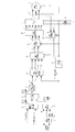
- FIG. 1 is a block diagram showing a main configuration of a control system to which the method for controlling an electric vehicle according to the first embodiment is applied.
- FIG. 2 is a block diagram showing details of the control system shown in FIG.
- FIG. 3 is a flow of processing of motor current control performed by the motor controller to which the control method of the electric vehicle according to the first embodiment is applied.
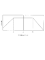
- FIG. 4 is a diagram showing an example of an accelerator opening degree-torque table.
- FIG. 5 is a diagram modeling a driving force transmission system of a vehicle.
- FIG. 6 is a diagram modeling a driving force transmission system of a vehicle.
- FIG. 7 is a block diagram for realizing the stop control process.
- FIG. 1 is a block diagram showing a main configuration of a control system to which the method for controlling an electric vehicle according to the first embodiment is applied.
- FIG. 2 is a block diagram showing details of the control system shown in FIG.
- FIG. 3 is a flow of processing of motor current control performed by the motor controller to which
- FIG. 8 is a diagram for explaining a method of estimating the vehicle body speed and calculating the vehicle body speed F / B torque.
- FIG. 9 is a diagram showing the relationship between the mass setting value and the mass setting gain in the first embodiment.
- FIG. 10 is a diagram for explaining a method of calculating a disturbance torque estimated value in the first embodiment.
- FIG. 11 is a block diagram for realizing the calculation process of the mass set value.
- FIG. 12 is a diagram showing an example of a functional configuration that realizes vibration damping control processing.
- FIG. 13 is a diagram showing an example of a bandpass filter.
- FIG. 14 is a diagram showing a comparative example of transmission characteristics used in the vibration damping control process.
- FIG. 15 is a diagram showing an example of a control result by the control device of the electric vehicle in the present embodiment.
- FIG. 16 is a diagram modeling the driving force transmission system of the vehicle according to the second embodiment.
- FIG. 17 is a block diagram for realizing the calculation process of the vehicle mass set value.
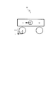
- FIG. 1 is a block diagram showing an example of a main system configuration of an electric vehicle to which the method for controlling an electric vehicle according to the first embodiment is applied.
- the electric vehicle control system 100 is applicable to an electric vehicle that includes an electric motor 4 as a part or all of the drive source of the vehicle and can travel by the driving force of the electric motor 4.
- Electric vehicles include not only electric vehicles but also hybrid vehicles and fuel cell vehicles.
- the electric vehicle control device illustrated in FIG. 1 controls acceleration / deceleration and stop of the vehicle only by operating the accelerator pedal.
- the driver of this electric vehicle depresses the accelerator pedal when accelerating, reduces the depressing amount of the accelerator pedal when decelerating or stopping, or operates the depressing amount of the accelerator pedal to zero.
- the vehicle On an uphill road, the vehicle may approach a stopped state while depressing the accelerator pedal in order to prevent the vehicle from moving backward.
- the motor controller 2 inputs signals indicating the vehicle state such as the vehicle body speed V, the accelerator opening AP, the rotor phase ⁇ of the electric motor 4, the currents iu, iv, and iwa of the electric motor 4 as digital signals. Then, the motor controller 2 generates a PWM signal for controlling the electric power supplied to the electric motor 4 based on the input signal, and supplies the generated PWM signal to the inverter 3 to press the switching element of the inverter 3. Open / close control.
- the inverter 3 converts the direct current supplied from the battery 1 into alternating current by turning on / off two switching elements (for example, power semiconductor elements such as IGBTs and MOS-FETs) for each phase. , A desired current is passed through the electric motor 4.
- switching elements for example, power semiconductor elements such as IGBTs and MOS-FETs
- the electric motor 4 is realized by, for example, a three-phase AC motor.
- the electric motor 4 generates a driving force by using the alternating current output from the inverter 3, and transmits the driving force to the left and right drive wheels 9a and 9b via the speed reducer 5 and the drive shaft 8. Further, the electric motor 4 recovers the kinetic energy of the electric vehicle as electric energy by generating a regenerative driving force when the electric motor 4 is rotated by the drive wheels 9a and 9b while the electric vehicle is traveling.
- the inverter 3 converts the alternating current generated during the regenerative operation of the electric motor 4 into a direct current and supplies it to the battery 1.
- the magnetic pole position sensor 6 is realized by, for example, a resolver or an encoder, and detects the rotor phase ⁇ of the electric motor 4.
- the current sensor 7 detects the three-phase alternating currents iu, iv and iwa supplied to the electric motor 4. However, since the sum of the three-phase alternating currents iu, iv, and iwa is 0 (zero), the current of any two phases may be detected and the current of the remaining one phase may be obtained by calculation.
- FIG. 2 is a block diagram showing the details of the controller 2 of the vehicle control system 100 to which the electric vehicle control method of the first embodiment is applied.
- the same components as those in FIG. 1 are designated by the same reference numerals, and description thereof will be omitted.
- the controller 2 of the present embodiment has, as its functional parts, a driving force map vault 20, a stop controller 21, a torque comparator 22, a vehicle mass setting device 23, a vibration damping controller 24, a current / voltage map vault 25, and a current. It includes a controller 26, coordinate converters 27 and 29, a PWM converter 28, and a rotation speed calculator 30.
- the driving force map reservoir 20 executes the basic torque target value calculation process (see step S201 described later).
- the driving force map vault 20 stores (stores) an accelerator opening-torque table, which will be described later, calculates a first torque target value Tm1 based on the accelerator opening ⁇ and the motor rotation speed, and is a torque comparator. Output to 22.
- the stop controller 21 and the torque comparator 22 execute the stop control process (see step S203 described later).
- the stop controller 21 determines the rotation speed of the drive shaft (drive shaft) 8 connected to the electric motor 4 when the vehicle is stopped, based on the final torque command value Tmff * , the motor rotation angular velocity ⁇ mf, and the vehicle mass estimation value M ⁇ .
- a second torque target value Tm2 that converges to the disturbance torque estimated value Td as the correlated speed parameter decreases is calculated and output to the torque comparator 22.
- the torque comparator 22 compares the first torque target value Tm1 and the second torque target value Tm2, and outputs the larger value as the third torque target value Tm3 to the vibration damping controller 24.
- the vibration damping controller 24 executes the vibration damping control process (see step S204 described later).
- the vibration damping controller 24 performs vibration damping control processing that suppresses driving force transmission system vibration such as torsional vibration of the drive shaft with respect to the target torque command value Tm3 * , and calculates the final torque command value Tmff * .
- the final torque command value Tmff * is output to the current-voltage map reservoir 25.
- the current-voltage map storage 25 stores in advance a map using the final torque command value Tmff * , the rotational angular velocity ⁇ mf of the motor, and the voltage detection value Vdc of the battery 1 input to the inverter 3 as indexes. Then, the current-voltage map reservoir 25 refers to the dq-axis current command value from the input final torque command value Tmff * , the motor rotation angular velocity ⁇ mf, and the voltage detection value Vdc of the battery 1 by referring to the above map.
- the id * , iq * and dq-axis non-interference voltage command values Vd_dcpl * and Vq_dcpl * are calculated and output to the current controller 26.
- the voltage detection value Vdc is acquired by a signal transmitted from a voltage sensor (not shown) provided in the DC power supply line from the battery 1 or a battery controller (not shown).
- the dq-axis current command values id * , iq * , dq-axis non-interfering voltage command values Vd_dcpl * , Vq_dcpl * , and the dq-axis current detection values id, iq output from the coordinate converter 29 are input to the current controller 26. Will be done. Then, the current controller 26 causes the dq-axis current detection values id and iq to follow the dq-axis current command values id * and iq * with desired responsiveness without steady deviation, and the dq-axis voltage command values Vd * and Vq *. Is calculated and output to the coordinate converter 27.
- the current controller 26 of the present embodiment can be realized by a simple PI feedback compensator or a known compensator such as a so-called robust model matching compensator.
- the coordinate converter 27 inputs the dq-axis voltage command values Vd * and Vq * and the magnetic pole position detection value ⁇ of the rotor included in the motor 4, and performs coordinate conversion processing using the following equation (1) to perform coordinate conversion processing for each uvw. Calculate the phase voltage command values v * u, v * v, v * w. The calculated value is output to the PWM converter 28.
- PWM converter 28 the voltage command values v * u, v * v, v * high-power element for driving the switching elements of the inverter 3 in accordance with w driving signal Duu *, Dul *, Dvu * , Dvl *, Dwu * And Dwl * are generated and output to the inverter 3. Then, inverter 3, high-power element drive signals Duu *, Dul *, Dvu * , Dvl * conversion, DWU *, Dwl * accordance AC voltages vu DC voltage of the battery 1 by driving the switching element, vv, the vw And supplies it to the electric motor 4.
- At least two phase currents (for example, u phase, v phase iu, iv) detected by the current sensor 7 are input to the coordinate converter 29.
- the coordinate converter 29 obtains the current value of the remaining one phase (for example, W phase iw) that was not detected by the current sensor 7 by the following equation (2).
- the coordinate converter 29 calculates the dq-axis current command values id * and iq * by performing coordinate conversion processing on the three-phase current values iu, iv, and iwa using the following equation (3). ..
- the calculated value is output to the current controller 26.
- the rotation speed calculator 30 calculates the rotation angular velocity ⁇ mf of the electric motor 4 from the magnetic pole position ⁇ of the electric motor 4 output from the magnetic pole position sensor 6, and outputs the rotation angular velocity ⁇ mf to the current / voltage map reservoir 25 and the stop controller 21. To do.
- the front motor rotation angular velocity ⁇ mf can also be obtained by detecting the rotor phase ⁇ of the electric motor 4 and differentiating the rotor phase ⁇ .
- FIG. 3 is a flowchart showing the flow of processing of motor current control performed by the motor controller 2.
- step S201 the motor controller 2 inputs a signal indicating the operating state of the electric vehicle.
- the operating states referred to here are the DC voltage value Vdc (V) between the battery 1 and the inverter 3, the vehicle body speed V (km / h) of the electric vehicle, the accelerator opening AP (%), and the rotation of the electric motor 4.
- the vehicle body speed V (km / h) is acquired by communication from a vehicle speed sensor (not shown) or from another controller.
- the motor controller 2 obtains the vehicle speed v (m / s) by multiplying the rotor mechanical angular velocity ⁇ m by the tire driving radius R and dividing by the gear ratio of the final gear, and the vehicle speed v (m / s) is 3600 /. By multiplying by 1000, the unit is converted to obtain the vehicle body speed V (km / h).
- the accelerator opening AP (%) is acquired from an accelerator opening sensor (not shown) or by communication from another controller such as a vehicle controller (not shown).
- the rotor phase ⁇ (rad) of the electric motor 4 is acquired from the magnetic pole position sensor 6.
- the rotation speed Nm (rpm) of the electric motor 4 is obtained by multiplying the motor rotation speed ⁇ m (rad / s), which is the mechanical angular velocity of the electric motor 4, by 60 / (2 ⁇ ).
- the motor rotation speed ⁇ m (rad / s) is obtained by dividing the rotor angular velocity ⁇ (electric angle) by the number of pole pairs p of the electric motor 4.
- the rotor angular velocity ⁇ is obtained by differentiating the rotor phase ⁇ .
- the currents iu, iv, and iwa (A) flowing through the electric motor 4 are acquired from the current sensor 7.
- the DC voltage value Vdc (V) is a power supply voltage obtained from a voltage sensor (not shown) provided in the DC power supply line between the battery 1 and the inverter 3 or transmitted by a battery controller (not shown). Obtained from the value.
- step S202 the motor controller 2 sets the first torque target value Tm1. Specifically, the motor controller 2 sets the first torque target value Tm1 based on the accelerator opening AP and the motor rotation speed input in step S201, for example, by referring to the accelerator opening-torque table. To do. The motor controller 2 may set the first torque target value Tm1 by referring to the accelerator opening-torque table based on the motor rotation speed ⁇ m instead of the motor rotation speed.
- the motor torque is set so that the amount of motor regeneration is large when the accelerator opening is 0 (fully closed). That is, when the motor rotation speed shows a positive value and at least when the accelerator opening degree is 0 (fully closed), a negative motor torque is set so that a regenerative braking force acts on the electric vehicle.
- the accelerator opening-torque table shown is an example, and is not limited to the one shown in FIG.
- step S203 the motor controller 2 (torque comparator 22) performs a stop control process. Specifically, the motor controller 2 determines when the electric vehicle is about to stop, and sets the first torque target value Tm1 calculated in step S202 to the motor torque command value Tm3 * before the electric vehicle is about to stop. Immediately after the vehicle is stopped, the second torque target value Tm2 that converges to the disturbance torque command value Td * as the motor rotation speed decreases is set to the motor torque command value Tm3 * .
- the second torque target value Tm2 is positive torque on an uphill road, negative torque on a downhill road, and approximately zero on a flat road. As a result, as will be described later, the vehicle can be smoothly stopped and the stopped state can be maintained by the second torque target value regardless of the slope of the road surface. The details of the stop control process will be described later.
- step S204 the motor controller 2 (vibration damping controller 24) performs vibration damping control processing that suppresses driving force transmission system vibration such as torsional vibration of the drive shaft 8 without wasting the drive shaft torque.
- the motor controller 2 calculates the motor torque command value Tmff * to which the vibration suppression control process is applied, based on the motor torque command value Tm3 * set in step S202 and the motor rotation speed ⁇ m.
- the details of the vibration damping control process will be described later. In the following description, it is assumed that the first torque target value Tm1 is set based on the motor rotation speed ⁇ m.
- step S205 the motor controller 2 (current / voltage map enclosure 25) has a d-axis current target value id and a q-axis current target value based on the motor torque command value Tmff * , the motor rotation speed ⁇ m, and the DC voltage value Vdc.
- Find iq For example, a table for obtaining the relationship between the motor torque command value, the motor rotation speed, and the DC voltage value and the d-axis current target value and the q-axis current target value through experimental results and simulation results is prepared in advance.
- step S206 the motor controller 2 (current / voltage map storage 25) performs current control for matching the d-axis current id and the q-axis current iq with the d-axis current target value id and the q-axis current target value iq, respectively. ..
- the motor controller 2 (current controller 26) has a d-axis current based on the three-phase AC current values iu, iv, and iwa input in step S201 and the rotor phase ⁇ of the electric motor 4. Find the id and q-axis current iq. Subsequently, the motor controller 2 calculates the d-axis and q-axis voltage command values vd and vq from the deviations between the d-axis and q-axis current target values id and iq and the d-axis and q-axis currents id and iq.
- the non-interference voltage required to cancel the interference voltage between the dq orthogonal coordinate axes is added to the d-axis and q-axis voltage command values vd and vq calculated by the motor controller 2. Good.
- the motor controller 2 uses the d-axis and q-axis voltage command values vd and vq, the rotor phase ⁇ of the electric motor 4, and the three-phase AC voltage command values vu * , vv * and vw *. And the DC voltage value Vdc, the PWM signals tu (%), tv (%) and tw (%) are obtained.
- the electric motor 4 can be driven with a desired torque indicated by the motor torque command value Tmff *. ..
- 5 and 6 are views that model the driving force transmission system of the vehicle, and each parameter in the figure is as shown below.
- the transfer characteristic Gp (s) which is the transfer function from the motor torque Tm of the electric motor 4 to the motor rotation speed ⁇ m, is obtained by the following equation. It is represented by (9).
- the transmission characteristic Gp (s) is also used as a vehicle model Gp (s) that simulates the transmission characteristic.
- the transmission characteristic Gp (s) can be approximated to the transmission characteristic as shown in the following equation (11), and one pole. And one zero show very close values. This means that ⁇ and ⁇ in the transfer characteristic Gp (s) of the formula (11) show extremely close values.
- the vehicle model Gp (s) of the equation (12) can be regarded as the transmission characteristic Gr (s) shown in the following equation (13).
- the transmission characteristic GpF (s) from the motor torque Tm to the driving force F of the electric vehicle will be described.
- the transmission characteristic GpF (s) is expressed by the following equation (16).
- FIG. 7 is a block diagram showing an example of a functional configuration that realizes stop control processing.
- FIG. 7 shows the vehicle body speed F / B torque setter 101, the disturbance torque estimator 102, the subtractor 103, the torque comparator 104, and the vehicle mass setter 105 as functional configurations for realizing the stop control process. ,It is shown.
- the vehicle body speed F / B torque setter 101 uses the regenerative braking force of the electric motor 4 to stop the electric vehicle based on the detected motor rotation speed ⁇ m, and the vehicle body speed feedback torque T ⁇ (hereinafter, vehicle body speed F). / B torque T ⁇ ) is calculated.
- FIG. 8 is a diagram showing details of the vehicle body speed F / B torque setter 101, and is a diagram for explaining a method of calculating the vehicle body speed F / B torque T ⁇ based on the motor rotation speed ⁇ m.
- the vehicle body speed F / B torque setting device 101 includes a control block 201 and a multiplier 202.
- the control block 201 has a function as a filter that simulates or approximates the transmission characteristic G ⁇ v (s) of the above equation (15), that is, a filter having the transmission characteristic G ⁇ v (s). Therefore, the control block 201 inputs the motor rotation speed ⁇ m and performs filtering processing in consideration of the transmission characteristic G ⁇ v (s) to calculate the estimated vehicle body speed V ⁇ indicating the estimated value of the vehicle body speed V.
- control block 201 may perform filtering processing using the transmission characteristic G ⁇ v (s) of the equation (17) instead of the transmission characteristic G ⁇ v (s) of the equation (15).
- the arithmetic processing can be reduced as compared with the case where the transfer characteristic G ⁇ v (s) of the equation (15) is used.
- the pole ⁇ p specified by the equation (16) may be used instead of the time constant ⁇ v in the above equation (17).
- the estimated vehicle speed V ⁇ can be calculated by using one pole of the denominator of the transmission characteristic from the motor rotation speed ⁇ m to the vehicle body speed V.
- control block 201 in addition to the transmission characteristic G ⁇ v (s) from the motor rotation speed ⁇ m of the above formula (15) to the vehicle body speed V, from the motor torque Tm of the above formula (16) to the driving force F of the electric vehicle.
- the filtering process may be performed in consideration of the transmission characteristic GpF (s) of the above.
- the control block 201 performs a filtering process having the transmission characteristic G ⁇ v (s) of the following equation (18).
- a third torque target which is a motor torque command value considering the transmission characteristic from the motor torque Tm to the driving force F of the electric vehicle.
- the value Tm3 can be calculated.
- transmission characteristic GpF (s) of the following equation (19) may be used instead of the transmission characteristic GpF (s) of the equation (16).
- the transmission characteristic GpF (s) of the above equation (19) is a characteristic that approximates the pole ⁇ far from the origin on the complex plane in the transmission characteristic GpF (s) of the equation (16).
- control block 201 calculates the estimated vehicle body speed V ⁇ by using one or more poles of the denominator specified by the transmission characteristic G ⁇ v (s) from the motor rotation speed ⁇ m to the vehicle body speed V.
- the multiplier 202 calculates the vehicle body speed F / B torque T ⁇ by multiplying the estimated vehicle body speed V ⁇ by a predetermined gain Kvref.
- the vehicle mass estimation value M ⁇ set in the vehicle mass setting device 105 (see FIG. 7) is input to the multiplier 202.
- the multiplier 202 determines the gain Kvref according to the input vehicle mass estimate M ⁇ . Details of the vehicle mass setting device 105 will be described later.
- this gain Kvref may be derived in advance by simulation, experiment, or the like, and stored in the multiplier 202 in a table format associated with the vehicle mass estimated value M ⁇ and the estimated vehicle body speed V ⁇ . ..
- the multiplier 202 refers to this table when calculating the vehicle body speed F / B torque, and determines the gain Kvref according to the vehicle mass estimation value M ⁇ .
- FIG. 9 is a diagram showing an example of the relationship between the vehicle mass estimated value M ⁇ and the gain Kvref.
- the design mass Mini in FIG. 9 is the mass of the vehicle itself at the time of shipment, and the estimated vehicle mass M ⁇ is the total mass of the vehicle when a person gets on the vehicle or luggage is loaded.
- the total mass of the vehicle in the present embodiment is the mass of the occupant of the vehicle, the mass of the load of the vehicle, the trailer T, etc., with respect to the design mass Mini, which is the mass of the vehicle itself. It is the total mass of the vehicle including the mass such as the mass of T.
- the design mass Mini does not necessarily have to be the value of the mass of only the vehicle, for example, the mass of several occupants may be included in advance.
- the absolute value of the gain Kvref is set larger according to the increase of the vehicle mass estimated value M ⁇ .
- the gain Kvref is premised on taking a negative value in order to stop the electric vehicle just before the electric vehicle stops.
- the vehicle body speed F / B torque T ⁇ is set to a torque value so that a larger regenerative braking force can be obtained as the estimated vehicle body speed V ⁇ increases.
- the vehicle body speed F / B torque setting device 101 has been described as calculating the vehicle body speed F / B torque T ⁇ by multiplying the estimated vehicle body speed V ⁇ by the gain Kvref, the estimated vehicle body speed V ⁇ and the regenerative torque are
- the vehicle body speed F / B torque T ⁇ may be calculated using a regenerative torque table in which the relationship is stored in advance or a damping rate table in which the attenuation rate of the estimated vehicle body speed V ⁇ is stored in advance.
- the disturbance torque estimator 102 shown in FIG. 7 calculates the disturbance torque estimation value Td based on the motor rotation speed ⁇ m, the third torque target value Tm3, and the vehicle mass estimation value M ⁇ .
- FIG. 10 is a diagram showing details of the disturbance torque estimator 102.
- the disturbance torque estimator 102 includes a control block 301, a control block 302, and a subtractor 303.
- the control block 301 has a function as a filter having a transmission characteristic of H1 (s) / Gr (s), and a first motor torque estimated value is performed by inputting a motor rotation speed ⁇ m and performing a filtering process. Is calculated.
- Gr (s) constituting the denominator is the transmission characteristic shown in the above equation (10), and is the vehicle model Gp (s) of the equation (9) and the vibration damping control algorithm. It is a vehicle model derived from.
- H1 (s) constituting the numerator of the transfer characteristic is a low-pass filter having a transmission characteristic in which the difference between the denominator order and the numerator order is equal to or larger than the difference between the denominator order and the numerator order of the vehicle model Gp (s). ..
- the vehicle mass estimation value M ⁇ set by the vehicle mass setting device 105 is input to the control block 301.
- the control block 301 corrects the mass component contained in Gr (s) constituting the denominator according to the input vehicle mass estimation value M ⁇ . Specifically, for example, by correcting M included in b 1 of the equation (10) to the vehicle mass estimated value M ⁇ , the transmission characteristic Gr (S) of the equation (13) including the b 1 becomes the vehicle mass estimated value. It is corrected based on M ⁇ . As a result, the first motor torque estimated value calculated in the control block 301 is calculated as a value corresponding to the vehicle mass estimated value M ⁇ .
- the control block 302 functions as a filter having a transmission characteristic H1 (s), and by inputting a third torque target value Tm3 and performing a filtering process in consideration of the transmission characteristic H1 (s), the control block 302 functions.
- the second motor torque estimate is calculated.
- the subtractor 303 outputs the deviation between the first motor torque estimated value and the second motor torque estimated value as the disturbance torque estimated value Td.
- the subtractor 303 of the present embodiment calculates the disturbance torque estimated value Td by subtracting the first motor torque estimated value from the second motor torque estimated value.
- the vehicle mass setting device 105 shown in FIG. 7 sets a vehicle mass estimated value M ⁇ which is the total mass of the vehicle based on the parameters acquired by the sensor provided in the vehicle and the third torque target value Tm3.
- FIG. 11 is a diagram showing details of the vehicle mass setting device 105.
- the vehicle mass setting device 105 includes a sensor signal processing unit 401, an acceleration estimation unit 402, an acceleration change amount calculation unit 403, a correction mass calculation unit 404, a vehicle mass setting unit 405, a driving force calculation unit 406, and The acceleration calculation unit 407 is provided.
- the sensor signal processing unit 401 inputs an output value from a sensor (not shown) provided in the vehicle.
- the sensor in the present embodiment is a sensor that acquires the front-rear acceleration a of the vehicle, for example, an acceleration sensor.
- the sensor signal processing unit 401 calculates the absolute value and outputs it to the acceleration change amount calculation unit 403.
- the acceleration estimation unit 402 calculates the absolute value and outputs it to the acceleration change amount calculation unit 403.
- the acceleration change amount calculation unit 403 calculates the acceleration difference ⁇ a, which is the difference between the input absolute value of the front-back acceleration a and the absolute value of the front-back acceleration estimated value a ⁇ .
- the correction mass calculation unit 404 inputs the acceleration difference ⁇ a calculated by the acceleration change amount calculation unit 403.
- the correction mass calculation unit 404 calculates the correction mass ⁇ M by multiplying the input acceleration difference ⁇ a by the mass setting gain Km.
- the gain Km is obtained in advance by simulation or the like, and is stored in a table format as a value associated with the acceleration difference ⁇ a and the correction mass ⁇ M.
- the vehicle mass setting unit 405 is input with the correction mass ⁇ M output from the correction mass calculation unit 404.
- the vehicle mass setting unit 405 calculates the vehicle mass estimation value M ⁇ by adding the received correction mass ⁇ M for each calculation.
- a third torque target value Tm3 is input to the driving force calculation unit 406.
- the driving force calculation unit 406 calculates the driving force F by applying the transmission characteristic Gpf (s) to the received third torque target value Tm3.
- the acceleration calculation unit 407 calculates the front-rear acceleration estimated value a ⁇ as the estimated value of the front-rear acceleration based on the vehicle mass estimation value M ⁇ from the vehicle mass setting unit 405 and the driving force F from the driving force calculation unit 406. To do. Specifically, the front-rear acceleration estimated value a ⁇ is derived by dividing the driving force F by the vehicle mass estimated value M ⁇ .
- the front-back acceleration estimation value a ⁇ is input to the acceleration estimation unit 402 as described above, and is used in the calculation of the acceleration difference ⁇ a. As described above, the acceleration difference ⁇ a can be calculated at all times during traveling, and the correction mass ⁇ M can also be calculated at all times during traveling.
- the vehicle mass estimation value M ⁇ is initially set according to a predetermined operation of the driver performed before the total mass of the electric vehicle changes. It may be converted.
- a predetermined operation for example, when a shift operation for switching the shift lever to the P range or parking is performed, the vehicle mass setting unit 405 initializes the vehicle mass estimation value M ⁇ according to the predetermined operation. It may be configured in. After the driver performs such an operation, there is a high possibility that the vehicle mass estimated value M ⁇ will change, for example, when the driver stops the vehicle and gets on and off the occupant.
- the controller 2 detects the possibility that the total mass M of the vehicle changes based on such an operation of the driver, and initializes the estimated vehicle mass M ⁇ before the estimated vehicle mass M ⁇ changes. May be good. As a result, even when the vehicle mass estimation value M ⁇ changes, the vehicle mass estimation value M ⁇ after the change can be appropriately estimated based on the front-rear acceleration a.
- the predetermined operation is such. The operation is not limited to the shift operation, and may be an operation such as turning off the IGN, removing the seat belt, or opening the back door.
- the subtractor 103 subtracts the disturbance torque estimated value Td from the disturbance torque estimator 102 from the vehicle body speed F / B torque T ⁇ from the vehicle body speed F / B torque setter 101 to obtain a second torque target value Tm2. Is calculated.
- the torque comparator 104 compares the magnitudes of the first torque target value Tm1 and the second torque target value Tm2, and sets the torque target value having the larger value to the third torque target value Tm3. While the vehicle is running, the second torque target value Tm2 is smaller than the first torque target value Tm1. Will also grow. Therefore, if the first torque target value Tm1 is larger than the second torque target value Tm2, the torque comparator 104 determines that the vehicle is about to stop and sets the first torque target value Tm1 to the third torque target value Tm3. Set to.
- the torque comparator 104 determines that the vehicle is about to stop when the second torque target value Tm2 becomes larger than the first torque target value Tm1, and sets the third torque target value Tm3 as the first torque target.
- the value Tm1 is switched to the second torque target value Tm2.
- the second torque target value Tm2 converges to a positive torque on an uphill road, a negative torque on a downhill road, and almost zero on a flat road in order to maintain the stopped state.
- FIG. 12 is a block diagram showing an example of a functional configuration that realizes a vibration damping control process that suppresses vibration of the driving force transmission system of an electric vehicle.
- the vibration damping control process is composed of a combination of an F / F compensator and an F / B compensator.
- FIG. 12 shows a control block 501 as an F / F compensator, and an adder 502, a control block 503, a subtractor 504, a control block 505, and a multiplier 506 as F / B compensators. It is shown.
- the control block 501 functions as a filter having a transmission characteristic of Gr (s) / Gp (s), and inputs a third torque target value Tm3 to reduce torsional vibration of the electric vehicle. To calculate the fourth torque target value Tm4.
- Gp (s) constituting the denominator is the vehicle model Gp (s) of the formula (12), and Gr (s) constituting the molecule is the vehicle model Gp (s) and It is a vehicle model of the equation (13) derived from the vibration suppression control algorithm.
- the adder 502 outputs the sixth torque target value Tm6 by adding the output of the F / B compensator to the fourth torque target value Tm4 obtained by the feed forward control.
- the control block 503 has a function as a filter having a vehicle model Gp (s). Therefore, the control block 503 inputs the sixth torque target value Tm6 and performs filtering processing in consideration of the vehicle model Gp (s), thereby indicating the motor rotation speed estimated value ⁇ m indicating the estimated value of the motor rotation speed ⁇ m. Calculate ⁇ .
- the subtractor 504 outputs the deviation between the motor rotation speed estimated value ⁇ m ⁇ and the motor rotation speed ⁇ m.
- the subtractor 504 of the present embodiment outputs a value obtained by subtracting the motor rotation speed ⁇ m from the motor rotation speed estimated value ⁇ m ⁇ to the control block 505.
- the control block 505 functions as a filter having a transmission characteristic of H2 (s) / Gp (s), and the estimated value of the disturbance torque is obtained by inputting the deviation of the subtractor 504 and performing the filtering process.
- the estimated disturbance d ⁇ including is calculated.
- control block 505 a vehicle model derived from the vehicle model Gp (s) of the equation (12) and the vibration damping control algorithm, and H2 (s) constituting the numerator is the torsional vibration of the drive system. It is a bandpass filter having a transmission characteristic that serves as a feedback element that reduces only.
- the multiplier 506 multiplies the estimated disturbance d ⁇ from the control block 505 by the feedback gain K FB to calculate a fifth torque target value Tm5 in consideration of the control error of the motor rotation speed ⁇ m. Then, the adder 502 adds the fifth torque target value Tm5 to the fourth torque target value Tm4 * to calculate the sixth torque target value Tm6.
- the motor rotation speed ⁇ m is fed back to the sixth torque target value Tm6 that suppresses the occurrence of torsional vibration of the electric vehicle. By setting the motor rotation speed ⁇ m to the sixth torque target value Tm6 in this way, the torsional vibration of the electric vehicle can be suppressed.
- FIG. 13 is a diagram showing an example of a bandpass filter for realizing the transmission characteristic H2 (s). The greatest effect can be obtained by setting the characteristics of the filter as shown in the figure.
- the attenuation characteristic on the low-pass side and the attenuation characteristic on the high-pass side are substantially the same, and the torsional resonance frequency of the drive system is at the center of the pass band on the logarithmic axis (log scale). It is set to be near the part.
- the transmission characteristic H2 (s) is configured by using the first-order high-pass filter and the first-order low-pass filter
- the transmission characteristic H2 (s) is represented by the following equation (20)
- the frequency fp is the drive system. Is set to the torsional resonance frequency of, and k is set to an arbitrary value.
- ⁇ L 1 / (2 ⁇ f HC)
- f HC k ⁇ f p
- ⁇ H 1 / (2 ⁇ f LC)
- the third torque target value Tm3 becomes the final torque command value Tmff * .
- FIG. 14 shows, as a comparative example, an example of the control result by the conventional stop control, that is, the stop control when the total mass M of the vehicle is estimated and the torque command value is not calculated according to the estimated total mass M. It is a time chart.
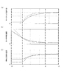
- FIG. 15 is a time chart showing an example of the control result in the stop control of the present embodiment when the stop control is performed based on the vehicle mass estimated value M ⁇ which is the estimated value of the total mass of the vehicle.
- FIGS. 14 and 15 (a) shows a third torque target value Tm3 as a final torque command value corresponding to the motor torque command value, and (b) shows the motor rotation speed, and (c). ) Indicates the vehicle front-rear acceleration.
- the horizontal axes of (a) to (c) are common time axes.
- the broken line in the figure is a line indicating stop control when the design mass Mini of the vehicle and the total mass of the actual vehicle match.
- the solid line in the figure is a line indicating stop control when the total mass of the actual vehicle is larger than the design mass Mini of the vehicle. The stop control starts at time t1.
- the stop control of the electric vehicle to which the present embodiment is applied as shown by the solid line in FIG. 15A, the total mass M of the vehicle increases with respect to the design mass Mini.
- the motor rotation speed asymptotically converges to zero from time t1 to time t2.
- the control error during stop control becomes smaller than that of the conventional technique of FIG. Therefore, even if the total mass M of the vehicle increases, it is possible to stop at the same timing as when the total mass of the vehicle and the design mass Mini match.
- the motor rotation speed ⁇ m becomes zero from the start of the stop control process, as shown in the solid line in FIG. 15 (b), while suppressing abrupt fluctuations in the vehicle front-rear acceleration.
- the period until convergence can be shortened from time t3 to time t2.
- the motor controller 2 of the present embodiment can realize the stop distance intended by the driver while ensuring the stability of the feedback control system. Therefore, according to the present embodiment, it is possible to shorten the stopping distance of the electric vehicle and realize a smooth stopping.
- the time from just before the stop to the stop and the behavior of the vehicle just before the stop can be matched regardless of the total mass of the vehicle. That is, even when the total mass of the electric vehicle changes, it is possible to suppress the long stopping distance of the electric vehicle and smoothly stop the electric vehicle.
- the parameters acquired by the sensor provided in the vehicle are not limited to the above-mentioned longitudinal acceleration a, and may be various parameters related to the change in the total mass M.
- the vehicle body speed V or the driving force F may be used instead of the front-rear acceleration a.
- the vehicle mass estimated value M ⁇ is calculated after the front-rear acceleration a and the estimated acceleration a ⁇ are calculated from the vehicle body speed V or the driving force F, or other parameters other than the accelerations a and a ⁇ are calculated from these. Therefore, the vehicle mass estimation value M ⁇ may be calculated. In this way, the types of parameters can be changed as appropriate.
- the electric vehicle control method of the present embodiment is a control method of an electric vehicle that uses the electric motor 4 as a traveling drive source and decelerates by the regenerative braking force of the electric motor 4.
- the accelerator operation amount is acquired, the total mass M ⁇ of the electric vehicle is acquired (estimated), the disturbance torque acting on the electric vehicle is estimated, and the rotation speed of the drive shaft 8 for driving the electric vehicle is correlated.
- Obtain the angular velocity of a certain rotating body estimate the vehicle body speed of the electric vehicle using the transmission characteristic Gp (s) from the angular velocity of the rotating body to the speed of the electric vehicle, and based on the acquired total mass M ⁇ of the electric vehicle.
- the second torque target value Tm2 (torque specified value) for the electric motor 4 is calculated, and the torque generated in the electric motor 4 is controlled based on the second torque target value Tm2. Further, in the control method, when the accelerator operation amount becomes equal to or less than a predetermined value and the electric vehicle stops, the estimated vehicle body speed V decreases and the second torque target value Tm2 converges to the disturbance torque Td.
- the second torque command value Tm2 * is calculated based on the total mass M ⁇ to control the torque generated in the electric motor 4, so that the control method depends on the total mass M ⁇ of the vehicle.
- the electric motor 4 can be controlled. Therefore, even if the total mass of the electric vehicle changes, the time from just before the stop to the stop and the behavior of the vehicle just before the stop can be matched with the normative response when the total mass of the vehicle is the same as the design mass Mini. Therefore, it is possible to prevent the electric vehicle from having a long stopping distance.
- the disturbance torque Td converges as the vehicle body speed V decreases, so that smooth deceleration without acceleration vibration can be realized just before the stop on flat roads, uphill roads, and downhill roads. It can be done and the stopped state can be maintained.
- the vehicle body speed feedback torque T ⁇ is calculated by multiplying the estimated vehicle body speed V ⁇ by a predetermined gain Kvref. Further, the second torque target value Tm2 (torque command value) is calculated based on the vehicle body speed feedback torque T ⁇ . Then, the predetermined gain Kvref is set according to the total mass M ⁇ of the electric vehicle.
- the second torque command value Tm2 * determined based on the vehicle body speed feedback T ⁇ also becomes the total mass M ⁇ of the vehicle.
- the corresponding value is calculated appropriately.
- the predetermined gain Kvref is set to be large according to the increase of the total mass M of the electric vehicle.
- the vehicle body speed F / B torque T ⁇ is adjusted to an appropriate value according to the total mass M ⁇ of the vehicle by increasing the gain Kvref as the total mass M of the vehicle increases. Can be done. As a result, it is possible to more reliably suppress the deviation between the torque calculated based on the transmission characteristic Gp (s) and the torque of the actual vehicle, so that stop control more suitable for the total mass M ⁇ of the vehicle can be realized.
- parameters correlated with the total mass of the electric vehicle are acquired, and the total mass M ⁇ of the electric vehicle is estimated based on the acquired parameters.
- a predetermined parameter correlating with the total mass of the electric vehicle is acquired without directly measuring the total mass of the electric vehicle, and the total mass M ⁇ is indirectly obtained based on this. Can be done. Therefore, since it is not necessary to separately provide a device for directly measuring the mass in the electric vehicle, the total mass M ⁇ of the electric vehicle can be estimated by a simple configuration.
- the parameters are the front-rear acceleration a of the electric vehicle, and the total mass M ⁇ of the electric vehicle is the acquired front-rear acceleration a of the electric vehicle and the second torque target value. It is estimated based on Tm2 (third torque target value Tm3).
- the corrected mass ⁇ M as the amount of change in the total mass M of the vehicle is obtained based on the front-rear acceleration a of the vehicle acquired by the acceleration sensor of the vehicle.
- the acceleration a can be obtained, for example, by an acceleration sensor that is easily attached to the vehicle.
- the total mass M ⁇ of the electric vehicle is initialized according to a predetermined operation performed before the total mass of the electric vehicle changes.
- the integration error can be reset, so that the vehicle mass estimate M ⁇ can be estimated accurately.
- stop control suitable for the total mass M ⁇ of the vehicle can always be realized.
- FIG. 16 is a diagram modeling the driving force transmission system of the vehicle.
- a case where the vehicle W pulls the trailer T will be described as an example.
- the vehicle W and the trailer T are connected by a trailer hitch F as a towing unit, and the trailer hitch F is a trailer hitch load sensor Ft for detecting the weight acting on the vehicle when the vehicle W pulls the trailer T. Is provided.
- suspensions corresponding to the wheels of the vehicle W, specifically, the left and right drive wheels 9a and 9b (see FIG. 1) and the left and right rear wheels (not shown), and each of these suspensions.
- Four suspension stroke sensors FR, FL, RR, and RL are provided to detect the stroke amount of the suspension stroke.
- FIG. 17 is a diagram showing details of the vehicle mass setting device 106.
- the vehicle mass setting device 106 includes a total stroke amount calculation unit 601, a suspension stroke change amount calculation unit 602, a vehicle increase mass calculation unit 603, a vehicle mass calculation unit 604, a driving force calculation unit 605, a vehicle driving force calculation unit 606, and a traction force ratio. It includes a calculation unit 607, a traction mass calculation unit 608, and a total mass calculation unit 609.
- the total stroke amount calculation unit 601 calculates the total stroke amount ST applied to the suspensions corresponding to all the drive wheels in the vehicle W by adding the outputs of the four suspension stroke sensors FR, FL, RR, and RL. This total stroke amount is acquired by, for example, a pressure sensor attached to the suspension mount or a stroke amount sensor.
- the suspension stroke change amount calculation unit 602 has the total stroke amount ST calculated by the total stroke amount calculation unit 601 and the design mass stroke amount STini as the total value of the stroke amounts of the four wheels predetermined by the design mass Mini. Entered.
- the suspension stroke change amount calculation unit 602 subtracts the total stroke amount ST from the design mass stroke amount STini, so that the stroke change as the suspension stroke amount sunk due to the influence of the increase in mass from the design mass Mini of the vehicle W. Calculate the quantity ⁇ ST.
- the vehicle increase mass calculation unit 603 multiplies the stroke change amount ⁇ ST calculated by the suspension stroke change amount calculation unit 602 by the spring constant Kst (N / mm) of the spring constituting the suspension to change the mass of the vehicle W.
- the quantity ⁇ Mc is calculated.
- the vehicle mass calculation unit 604 inputs the design mass Mini of the vehicle W and the vehicle mass fluctuation amount ⁇ M calculated by the vehicle increase mass calculation unit 603, and calculates the vehicle mass Mc of the vehicle W by adding these. As described above, the vehicle mass Mc of the vehicle W is calculated using the signals from the suspension stroke sensors FR, FL, RR, and RL indicating the suspension stroke amount.
- the driving force calculation unit 605 takes the third torque target value Tm3 as an input, and calculates the driving force F using the equation (16).
- the vehicle driving force calculation unit 606 inputs the driving force F of the vehicle W calculated by the driving force calculation unit 605 and the traction force Fto which is a weight detection value in the trailer hitch load sensor Ft.
- the traction force Fto referred to here is a value corresponding to the force with which the vehicle W pulls the trailer T.
- the vehicle driving force calculation unit 606 calculates the vehicle driving force Fw as the force for driving the vehicle W by subtracting the traction force Fto from the driving force F.
- the traction force ratio calculation unit 607 inputs the traction force Fto from the trailer hitch load sensor Ft and the vehicle driving force Fw calculated by the vehicle driving force calculation unit 606.
- the traction force ratio calculation unit 607 calculates the ratio Kt of the traction force Fto to the vehicle driving force Fw by dividing the vehicle driving force Fw from the traction force Fto.
- the ratio Kt calculated by the traction force ratio calculation unit 607 and the vehicle mass Mc of the vehicle W calculated by the vehicle mass calculation unit 604 are input.
- the traction mass calculation unit 608 calculates the trailer mass Mt as the mass of the trailer T by multiplying the vehicle mass Mc of the vehicle by the ratio Kt.
- the total mass calculation unit 609 estimates the vehicle mass as the total mass of the vehicle W and the trailer T by adding the vehicle mass Mc calculated by the vehicle mass calculation unit 604 and the trailer mass Mt calculated by the traction mass calculation unit 608. Calculate the value M ⁇ .
- the trailer mass Mt is estimated using the third torque target value Tm3 and the detected value of the load sensor Ft of the trailer hitch. Then, the vehicle mass estimated value M ⁇ is calculated by correcting the vehicle mass Mc of the vehicle using this trailer mass Mt.
- the controller 2 may initialize the vehicle mass estimation value M ⁇ when it detects a signal indicating that the shift operation has been performed by the driver.
- the total mass M ⁇ of the vehicle can be estimated using the suspension stroke sensors FR, FL, RR, and RL without the need for a load sensor.
- Mc output from the vehicle mass calculation unit 604 is calculated as the total mass M ⁇ of the vehicle.
- the parameter is the stroke amount of the suspension provided in the electric vehicle, and the total mass M ⁇ of the electric vehicle is estimated based on the acquired stroke amount.
- the vehicle mass estimation value M ⁇ can be appropriately estimated by indirectly calculating the vehicle mass change amount ⁇ M based on the parameters indicating the stroke amounts of the suspension stroke sensors FR, FL, RR, and RL. be able to.
- the electric vehicle W further includes a trailer hitch (towing portion) F for towing a trailer T (another object), and the electric vehicle W pulls the trailer T. Measure the load applied to the trailer hitch F. Further, when the electric vehicle W pulls the trailer T, the total mass M ⁇ of the electric vehicle is corrected based on the load Fto applied to the trailer hitch F and the second torque target value (torque command value) Tm2.
- the above embodiments are only a part of the application examples of the present invention, and the technical scope of the present invention is limited to the specific configuration of the above embodiments. Absent.
- the above embodiments can be appropriately combined as long as there is no contradiction.
- the method for controlling an electric vehicle according to the first embodiment can also be applied to a vehicle to which a trailer shown in FIG. 16 is connected. In that case, the total mass of the vehicle to which the trailer is connected can be calculated based on the front-rear acceleration sensor a by the same method as that described with reference to FIG.
- the total mass M ⁇ is estimated based on a predetermined parameter, but it may be measured by providing a configuration capable of directly measuring the mass.
- the total mass M ⁇ may be directly measured by a method such as providing a sensor capable of measuring the mass. In this way, the total mass M ⁇ is obtained by various methods.
Landscapes
- Engineering & Computer Science (AREA)
- Power Engineering (AREA)
- Transportation (AREA)
- Mechanical Engineering (AREA)
- Electric Propulsion And Braking For Vehicles (AREA)
Priority Applications (5)
| Application Number | Priority Date | Filing Date | Title |
|---|---|---|---|
| PCT/JP2019/013434 WO2020194621A1 (ja) | 2019-03-27 | 2019-03-27 | 電動車両の制御装置及び電動車両の制御方法 |
| EP19920660.8A EP3950402B1 (en) | 2019-03-27 | 2019-03-27 | Control apparatus for electric vehicle and control method for electric vehicle |
| US17/442,998 US11801757B2 (en) | 2019-03-27 | 2019-03-27 | Control device for electric vehicle and control method for electric vehicle |
| CN201980094376.4A CN113631416B (zh) | 2019-03-27 | 2019-03-27 | 电动车辆的控制装置以及电动车辆的控制方法 |
| JP2021508565A JP7201071B2 (ja) | 2019-03-27 | 2019-03-27 | 電動車両の制御装置及び電動車両の制御方法 |
Applications Claiming Priority (1)
| Application Number | Priority Date | Filing Date | Title |
|---|---|---|---|
| PCT/JP2019/013434 WO2020194621A1 (ja) | 2019-03-27 | 2019-03-27 | 電動車両の制御装置及び電動車両の制御方法 |
Publications (1)
| Publication Number | Publication Date |
|---|---|
| WO2020194621A1 true WO2020194621A1 (ja) | 2020-10-01 |
Family
ID=72610315
Family Applications (1)
| Application Number | Title | Priority Date | Filing Date |
|---|---|---|---|
| PCT/JP2019/013434 Ceased WO2020194621A1 (ja) | 2019-03-27 | 2019-03-27 | 電動車両の制御装置及び電動車両の制御方法 |
Country Status (5)
| Country | Link |
|---|---|
| US (1) | US11801757B2 (https=) |
| EP (1) | EP3950402B1 (https=) |
| JP (1) | JP7201071B2 (https=) |
| CN (1) | CN113631416B (https=) |
| WO (1) | WO2020194621A1 (https=) |
Cited By (1)
| Publication number | Priority date | Publication date | Assignee | Title |
|---|---|---|---|---|
| WO2023139810A1 (ja) * | 2022-01-18 | 2023-07-27 | 日産自動車株式会社 | 電動車両の制御方法、及び、電動車両の制御装置 |
Families Citing this family (6)
| Publication number | Priority date | Publication date | Assignee | Title |
|---|---|---|---|---|
| WO2023175993A1 (ja) | 2022-03-18 | 2023-09-21 | 日産自動車株式会社 | 電動車両の制御方法、及び、電動車両の制御装置 |
| WO2023175992A1 (ja) * | 2022-03-18 | 2023-09-21 | 日産自動車株式会社 | 発電機制御方法及び発電機制御装置 |
| CN115246325A (zh) * | 2022-04-01 | 2022-10-28 | 尼得科艾莱希斯电子(浙江)有限公司 | 马达的控制装置以及电动车辆 |
| JP2024025146A (ja) * | 2022-08-10 | 2024-02-26 | トヨタ自動車株式会社 | 車両コントローラ |
| KR20240052243A (ko) | 2022-10-14 | 2024-04-23 | 현대자동차주식회사 | 차량 및 그 제어 방법 |
| JP2025099353A (ja) * | 2023-12-21 | 2025-07-03 | トヨタ自動車株式会社 | 電気自動車 |
Citations (4)
| Publication number | Priority date | Publication date | Assignee | Title |
|---|---|---|---|---|
| JP2014096973A (ja) * | 2012-11-07 | 2014-05-22 | Hyundai Motor Company Co Ltd | 環境調和型車両の補助ブレーキ制御方法及び制御装置 |
| WO2015083213A1 (ja) * | 2013-12-02 | 2015-06-11 | 日産自動車株式会社 | 電動車両の制御装置および電動車両の制御方法 |
| JP2017139230A (ja) | 2017-03-16 | 2017-08-10 | かがつう株式会社 | 照明システムおよび照明制御方法 |
| JP2017159711A (ja) * | 2016-03-07 | 2017-09-14 | ちぐさ技研工業株式会社 | 傾斜地用軌条電動車 |
Family Cites Families (12)
| Publication number | Priority date | Publication date | Assignee | Title |
|---|---|---|---|---|
| JPH06245331A (ja) * | 1993-02-18 | 1994-09-02 | East Japan Railway Co | 電気車の応荷重制御装置 |
| JP4000938B2 (ja) * | 2002-07-30 | 2007-10-31 | 株式会社明電舎 | 電動車輛の制御方法 |
| US8583354B2 (en) * | 2011-04-06 | 2013-11-12 | Robert Bosch Gmbh | Continuous computation of center of gravity of a vehicle |
| JP5803594B2 (ja) * | 2011-11-15 | 2015-11-04 | 三菱自動車工業株式会社 | 出力特性制御方法 |
| JP6330820B2 (ja) * | 2013-12-02 | 2018-05-30 | 日産自動車株式会社 | 電動車両の制御装置および電動車両の制御方法 |
| DE102014002677A1 (de) * | 2014-02-28 | 2015-09-03 | Westfalia-Automotive Gmbh | Anhängekupplung mit einer Auswerteeinrichtung, Auswerteeinrichtung und Auswerteverfahren |
| WO2016120979A1 (ja) * | 2015-01-26 | 2016-08-04 | 日産自動車株式会社 | 電動車両の制御装置および電動車両の制御方法 |
| WO2016120978A1 (ja) * | 2015-01-26 | 2016-08-04 | 日産自動車株式会社 | 電動車両の制御装置および電動車両の制御方法 |
| US9840240B2 (en) | 2015-04-09 | 2017-12-12 | Ford Global Technologies, Llc | Trailer backup aid speed limiting via braking |
| US10189472B2 (en) * | 2016-04-13 | 2019-01-29 | Ford Global Technologies, Llc | Smart trailer classification system |
| US11027617B2 (en) * | 2017-01-24 | 2021-06-08 | Nissan Motor Co., Ltd. | Control method for electrically driven vehicle and control device for electrically driven vehicle |
| CN110234533B (zh) * | 2017-01-24 | 2020-09-15 | 日产自动车株式会社 | 电动车辆的控制方法以及控制装置 |
-
2019
- 2019-03-27 EP EP19920660.8A patent/EP3950402B1/en active Active
- 2019-03-27 WO PCT/JP2019/013434 patent/WO2020194621A1/ja not_active Ceased
- 2019-03-27 US US17/442,998 patent/US11801757B2/en active Active
- 2019-03-27 JP JP2021508565A patent/JP7201071B2/ja active Active
- 2019-03-27 CN CN201980094376.4A patent/CN113631416B/zh active Active
Patent Citations (4)
| Publication number | Priority date | Publication date | Assignee | Title |
|---|---|---|---|---|
| JP2014096973A (ja) * | 2012-11-07 | 2014-05-22 | Hyundai Motor Company Co Ltd | 環境調和型車両の補助ブレーキ制御方法及び制御装置 |
| WO2015083213A1 (ja) * | 2013-12-02 | 2015-06-11 | 日産自動車株式会社 | 電動車両の制御装置および電動車両の制御方法 |
| JP2017159711A (ja) * | 2016-03-07 | 2017-09-14 | ちぐさ技研工業株式会社 | 傾斜地用軌条電動車 |
| JP2017139230A (ja) | 2017-03-16 | 2017-08-10 | かがつう株式会社 | 照明システムおよび照明制御方法 |
Cited By (4)
| Publication number | Priority date | Publication date | Assignee | Title |
|---|---|---|---|---|
| WO2023139810A1 (ja) * | 2022-01-18 | 2023-07-27 | 日産自動車株式会社 | 電動車両の制御方法、及び、電動車両の制御装置 |
| JPWO2023139810A1 (https=) * | 2022-01-18 | 2023-07-27 | ||
| US12330508B2 (en) | 2022-01-18 | 2025-06-17 | Nissan Motor Co., Ltd. | Control method for electric vehicle and control device for electric vehicle |
| JP7726302B2 (ja) | 2022-01-18 | 2025-08-20 | 日産自動車株式会社 | 電動車両の制御方法、及び、電動車両の制御装置 |
Also Published As
| Publication number | Publication date |
|---|---|
| JPWO2020194621A1 (https=) | 2020-10-01 |
| EP3950402A1 (en) | 2022-02-09 |
| US20220185121A1 (en) | 2022-06-16 |
| CN113631416B (zh) | 2022-10-28 |
| JP7201071B2 (ja) | 2023-01-10 |
| EP3950402A4 (en) | 2022-03-30 |
| EP3950402B1 (en) | 2023-06-07 |
| US11801757B2 (en) | 2023-10-31 |
| CN113631416A (zh) | 2021-11-09 |
Similar Documents
| Publication | Publication Date | Title |
|---|---|---|
| US9845022B2 (en) | Control device for electric motor vehicle and control method for electric motor vehicle | |
| EP3078537B1 (en) | Electric vehicle control device and electric vehicle control method | |
| EP3251887B1 (en) | Control device for electric vehicle and control method for electric vehicle | |
| JP7201071B2 (ja) | 電動車両の制御装置及び電動車両の制御方法 | |
| JP6402783B2 (ja) | 電動車両の制御装置および電動車両の制御方法 | |
| EP3798044B1 (en) | Control device for electric motor vehicle and control method for electric motor vehicle | |
| CN114599544B (zh) | 电动车辆的控制方法及电动车辆的控制装置 | |
| EP3251906B1 (en) | Vehicle control device and vehicle control method | |
| JP7056219B2 (ja) | 電動車両の制御方法および電動車両の制御装置 | |
| JP6992298B2 (ja) | 電動車両の制御装置及び電動車両の制御方法 | |
| JP6880674B2 (ja) | 電動車両の制御方法、及び、電動車両の制御装置 | |
| JP7732348B2 (ja) | 電動車両の制御方法、電動車両の制御装置 |
Legal Events
| Date | Code | Title | Description |
|---|---|---|---|
| 121 | Ep: the epo has been informed by wipo that ep was designated in this application |
Ref document number: 19920660 Country of ref document: EP Kind code of ref document: A1 |
|
| ENP | Entry into the national phase |
Ref document number: 2021508565 Country of ref document: JP Kind code of ref document: A |
|
| NENP | Non-entry into the national phase |
Ref country code: DE |
|
| ENP | Entry into the national phase |
Ref document number: 2019920660 Country of ref document: EP Effective date: 20211027 |