EP3078537B1 - Electric vehicle control device and electric vehicle control method - Google Patents
Electric vehicle control device and electric vehicle control method Download PDFInfo
- Publication number
- EP3078537B1 EP3078537B1 EP13898783.9A EP13898783A EP3078537B1 EP 3078537 B1 EP3078537 B1 EP 3078537B1 EP 13898783 A EP13898783 A EP 13898783A EP 3078537 B1 EP3078537 B1 EP 3078537B1
- Authority
- EP
- European Patent Office
- Prior art keywords
- torque
- motor
- vehicle
- electric motor
- gain
- Prior art date
- Legal status (The legal status is an assumption and is not a legal conclusion. Google has not performed a legal analysis and makes no representation as to the accuracy of the status listed.)
- Active
Links
- 238000000034 method Methods 0.000 title claims description 41
- 230000001172 regenerating effect Effects 0.000 claims description 45
- 238000004364 calculation method Methods 0.000 claims description 20
- 230000007423 decrease Effects 0.000 claims description 20
- 230000001133 acceleration Effects 0.000 claims description 18
- 238000001514 detection method Methods 0.000 claims 8
- 238000010586 diagram Methods 0.000 description 23
- 230000005540 biological transmission Effects 0.000 description 20
- 230000008569 process Effects 0.000 description 20
- 230000036461 convulsion Effects 0.000 description 13
- 230000008859 change Effects 0.000 description 10
- 230000008929 regeneration Effects 0.000 description 6
- 238000011069 regeneration method Methods 0.000 description 6
- 230000009467 reduction Effects 0.000 description 4
- 238000006243 chemical reaction Methods 0.000 description 3
- 238000001914 filtration Methods 0.000 description 3
- 230000004043 responsiveness Effects 0.000 description 3
- 238000004891 communication Methods 0.000 description 2
- 230000000694 effects Effects 0.000 description 2
- 230000004044 response Effects 0.000 description 2
- 230000035939 shock Effects 0.000 description 2
- 230000015556 catabolic process Effects 0.000 description 1
- 239000003638 chemical reducing agent Substances 0.000 description 1
- 230000000295 complement effect Effects 0.000 description 1
- 239000000470 constituent Substances 0.000 description 1
- 238000006731 degradation reaction Methods 0.000 description 1
- 238000005516 engineering process Methods 0.000 description 1
- 239000000446 fuel Substances 0.000 description 1
- 238000009499 grossing Methods 0.000 description 1
- 230000010355 oscillation Effects 0.000 description 1
- 230000003534 oscillatory effect Effects 0.000 description 1
- 230000000717 retained effect Effects 0.000 description 1
- 230000000630 rising effect Effects 0.000 description 1
- 238000005096 rolling process Methods 0.000 description 1
- 239000004065 semiconductor Substances 0.000 description 1
- 238000004088 simulation Methods 0.000 description 1
Images


Classifications
-
- B—PERFORMING OPERATIONS; TRANSPORTING
- B60—VEHICLES IN GENERAL
- B60L—PROPULSION OF ELECTRICALLY-PROPELLED VEHICLES; SUPPLYING ELECTRIC POWER FOR AUXILIARY EQUIPMENT OF ELECTRICALLY-PROPELLED VEHICLES; ELECTRODYNAMIC BRAKE SYSTEMS FOR VEHICLES IN GENERAL; MAGNETIC SUSPENSION OR LEVITATION FOR VEHICLES; MONITORING OPERATING VARIABLES OF ELECTRICALLY-PROPELLED VEHICLES; ELECTRIC SAFETY DEVICES FOR ELECTRICALLY-PROPELLED VEHICLES
- B60L7/00—Electrodynamic brake systems for vehicles in general
- B60L7/10—Dynamic electric regenerative braking
- B60L7/14—Dynamic electric regenerative braking for vehicles propelled by ac motors
-
- B—PERFORMING OPERATIONS; TRANSPORTING
- B60—VEHICLES IN GENERAL
- B60L—PROPULSION OF ELECTRICALLY-PROPELLED VEHICLES; SUPPLYING ELECTRIC POWER FOR AUXILIARY EQUIPMENT OF ELECTRICALLY-PROPELLED VEHICLES; ELECTRODYNAMIC BRAKE SYSTEMS FOR VEHICLES IN GENERAL; MAGNETIC SUSPENSION OR LEVITATION FOR VEHICLES; MONITORING OPERATING VARIABLES OF ELECTRICALLY-PROPELLED VEHICLES; ELECTRIC SAFETY DEVICES FOR ELECTRICALLY-PROPELLED VEHICLES
- B60L15/00—Methods, circuits, or devices for controlling the traction-motor speed of electrically-propelled vehicles
- B60L15/20—Methods, circuits, or devices for controlling the traction-motor speed of electrically-propelled vehicles for control of the vehicle or its driving motor to achieve a desired performance, e.g. speed, torque, programmed variation of speed
- B60L15/2009—Methods, circuits, or devices for controlling the traction-motor speed of electrically-propelled vehicles for control of the vehicle or its driving motor to achieve a desired performance, e.g. speed, torque, programmed variation of speed for braking
- B60L15/2018—Methods, circuits, or devices for controlling the traction-motor speed of electrically-propelled vehicles for control of the vehicle or its driving motor to achieve a desired performance, e.g. speed, torque, programmed variation of speed for braking for braking on a slope
-
- B—PERFORMING OPERATIONS; TRANSPORTING
- B60—VEHICLES IN GENERAL
- B60L—PROPULSION OF ELECTRICALLY-PROPELLED VEHICLES; SUPPLYING ELECTRIC POWER FOR AUXILIARY EQUIPMENT OF ELECTRICALLY-PROPELLED VEHICLES; ELECTRODYNAMIC BRAKE SYSTEMS FOR VEHICLES IN GENERAL; MAGNETIC SUSPENSION OR LEVITATION FOR VEHICLES; MONITORING OPERATING VARIABLES OF ELECTRICALLY-PROPELLED VEHICLES; ELECTRIC SAFETY DEVICES FOR ELECTRICALLY-PROPELLED VEHICLES
- B60L3/00—Electric devices on electrically-propelled vehicles for safety purposes; Monitoring operating variables, e.g. speed, deceleration or energy consumption
- B60L3/08—Means for preventing excessive speed of the vehicle
-
- B—PERFORMING OPERATIONS; TRANSPORTING
- B60—VEHICLES IN GENERAL
- B60L—PROPULSION OF ELECTRICALLY-PROPELLED VEHICLES; SUPPLYING ELECTRIC POWER FOR AUXILIARY EQUIPMENT OF ELECTRICALLY-PROPELLED VEHICLES; ELECTRODYNAMIC BRAKE SYSTEMS FOR VEHICLES IN GENERAL; MAGNETIC SUSPENSION OR LEVITATION FOR VEHICLES; MONITORING OPERATING VARIABLES OF ELECTRICALLY-PROPELLED VEHICLES; ELECTRIC SAFETY DEVICES FOR ELECTRICALLY-PROPELLED VEHICLES
- B60L7/00—Electrodynamic brake systems for vehicles in general
- B60L7/10—Dynamic electric regenerative braking
- B60L7/18—Controlling the braking effect
-
- H—ELECTRICITY
- H02—GENERATION; CONVERSION OR DISTRIBUTION OF ELECTRIC POWER
- H02P—CONTROL OR REGULATION OF ELECTRIC MOTORS, ELECTRIC GENERATORS OR DYNAMO-ELECTRIC CONVERTERS; CONTROLLING TRANSFORMERS, REACTORS OR CHOKE COILS
- H02P3/00—Arrangements for stopping or slowing electric motors, generators, or dynamo-electric converters
- H02P3/06—Arrangements for stopping or slowing electric motors, generators, or dynamo-electric converters for stopping or slowing an individual dynamo-electric motor or dynamo-electric converter
- H02P3/08—Arrangements for stopping or slowing electric motors, generators, or dynamo-electric converters for stopping or slowing an individual dynamo-electric motor or dynamo-electric converter for stopping or slowing a dc motor
- H02P3/14—Arrangements for stopping or slowing electric motors, generators, or dynamo-electric converters for stopping or slowing an individual dynamo-electric motor or dynamo-electric converter for stopping or slowing a dc motor by regenerative braking
-
- H—ELECTRICITY
- H02—GENERATION; CONVERSION OR DISTRIBUTION OF ELECTRIC POWER
- H02P—CONTROL OR REGULATION OF ELECTRIC MOTORS, ELECTRIC GENERATORS OR DYNAMO-ELECTRIC CONVERTERS; CONTROLLING TRANSFORMERS, REACTORS OR CHOKE COILS
- H02P3/00—Arrangements for stopping or slowing electric motors, generators, or dynamo-electric converters
- H02P3/06—Arrangements for stopping or slowing electric motors, generators, or dynamo-electric converters for stopping or slowing an individual dynamo-electric motor or dynamo-electric converter
- H02P3/18—Arrangements for stopping or slowing electric motors, generators, or dynamo-electric converters for stopping or slowing an individual dynamo-electric motor or dynamo-electric converter for stopping or slowing an ac motor
-
- B—PERFORMING OPERATIONS; TRANSPORTING
- B60—VEHICLES IN GENERAL
- B60L—PROPULSION OF ELECTRICALLY-PROPELLED VEHICLES; SUPPLYING ELECTRIC POWER FOR AUXILIARY EQUIPMENT OF ELECTRICALLY-PROPELLED VEHICLES; ELECTRODYNAMIC BRAKE SYSTEMS FOR VEHICLES IN GENERAL; MAGNETIC SUSPENSION OR LEVITATION FOR VEHICLES; MONITORING OPERATING VARIABLES OF ELECTRICALLY-PROPELLED VEHICLES; ELECTRIC SAFETY DEVICES FOR ELECTRICALLY-PROPELLED VEHICLES
- B60L2240/00—Control parameters of input or output; Target parameters
- B60L2240/10—Vehicle control parameters
- B60L2240/12—Speed
-
- B—PERFORMING OPERATIONS; TRANSPORTING
- B60—VEHICLES IN GENERAL
- B60L—PROPULSION OF ELECTRICALLY-PROPELLED VEHICLES; SUPPLYING ELECTRIC POWER FOR AUXILIARY EQUIPMENT OF ELECTRICALLY-PROPELLED VEHICLES; ELECTRODYNAMIC BRAKE SYSTEMS FOR VEHICLES IN GENERAL; MAGNETIC SUSPENSION OR LEVITATION FOR VEHICLES; MONITORING OPERATING VARIABLES OF ELECTRICALLY-PROPELLED VEHICLES; ELECTRIC SAFETY DEVICES FOR ELECTRICALLY-PROPELLED VEHICLES
- B60L2240/00—Control parameters of input or output; Target parameters
- B60L2240/40—Drive Train control parameters
- B60L2240/42—Drive Train control parameters related to electric machines
- B60L2240/421—Speed
-
- B—PERFORMING OPERATIONS; TRANSPORTING
- B60—VEHICLES IN GENERAL
- B60L—PROPULSION OF ELECTRICALLY-PROPELLED VEHICLES; SUPPLYING ELECTRIC POWER FOR AUXILIARY EQUIPMENT OF ELECTRICALLY-PROPELLED VEHICLES; ELECTRODYNAMIC BRAKE SYSTEMS FOR VEHICLES IN GENERAL; MAGNETIC SUSPENSION OR LEVITATION FOR VEHICLES; MONITORING OPERATING VARIABLES OF ELECTRICALLY-PROPELLED VEHICLES; ELECTRIC SAFETY DEVICES FOR ELECTRICALLY-PROPELLED VEHICLES
- B60L2240/00—Control parameters of input or output; Target parameters
- B60L2240/40—Drive Train control parameters
- B60L2240/42—Drive Train control parameters related to electric machines
- B60L2240/423—Torque
-
- B—PERFORMING OPERATIONS; TRANSPORTING
- B60—VEHICLES IN GENERAL
- B60L—PROPULSION OF ELECTRICALLY-PROPELLED VEHICLES; SUPPLYING ELECTRIC POWER FOR AUXILIARY EQUIPMENT OF ELECTRICALLY-PROPELLED VEHICLES; ELECTRODYNAMIC BRAKE SYSTEMS FOR VEHICLES IN GENERAL; MAGNETIC SUSPENSION OR LEVITATION FOR VEHICLES; MONITORING OPERATING VARIABLES OF ELECTRICALLY-PROPELLED VEHICLES; ELECTRIC SAFETY DEVICES FOR ELECTRICALLY-PROPELLED VEHICLES
- B60L2240/00—Control parameters of input or output; Target parameters
- B60L2240/60—Navigation input
- B60L2240/64—Road conditions
- B60L2240/642—Slope of road
-
- B—PERFORMING OPERATIONS; TRANSPORTING
- B60—VEHICLES IN GENERAL
- B60L—PROPULSION OF ELECTRICALLY-PROPELLED VEHICLES; SUPPLYING ELECTRIC POWER FOR AUXILIARY EQUIPMENT OF ELECTRICALLY-PROPELLED VEHICLES; ELECTRODYNAMIC BRAKE SYSTEMS FOR VEHICLES IN GENERAL; MAGNETIC SUSPENSION OR LEVITATION FOR VEHICLES; MONITORING OPERATING VARIABLES OF ELECTRICALLY-PROPELLED VEHICLES; ELECTRIC SAFETY DEVICES FOR ELECTRICALLY-PROPELLED VEHICLES
- B60L2250/00—Driver interactions
- B60L2250/26—Driver interactions by pedal actuation
-
- H—ELECTRICITY
- H02—GENERATION; CONVERSION OR DISTRIBUTION OF ELECTRIC POWER
- H02P—CONTROL OR REGULATION OF ELECTRIC MOTORS, ELECTRIC GENERATORS OR DYNAMO-ELECTRIC CONVERTERS; CONTROLLING TRANSFORMERS, REACTORS OR CHOKE COILS
- H02P3/00—Arrangements for stopping or slowing electric motors, generators, or dynamo-electric converters
- H02P3/06—Arrangements for stopping or slowing electric motors, generators, or dynamo-electric converters for stopping or slowing an individual dynamo-electric motor or dynamo-electric converter
-
- Y—GENERAL TAGGING OF NEW TECHNOLOGICAL DEVELOPMENTS; GENERAL TAGGING OF CROSS-SECTIONAL TECHNOLOGIES SPANNING OVER SEVERAL SECTIONS OF THE IPC; TECHNICAL SUBJECTS COVERED BY FORMER USPC CROSS-REFERENCE ART COLLECTIONS [XRACs] AND DIGESTS
- Y02—TECHNOLOGIES OR APPLICATIONS FOR MITIGATION OR ADAPTATION AGAINST CLIMATE CHANGE
- Y02T—CLIMATE CHANGE MITIGATION TECHNOLOGIES RELATED TO TRANSPORTATION
- Y02T10/00—Road transport of goods or passengers
- Y02T10/60—Other road transportation technologies with climate change mitigation effect
- Y02T10/64—Electric machine technologies in electromobility
-
- Y—GENERAL TAGGING OF NEW TECHNOLOGICAL DEVELOPMENTS; GENERAL TAGGING OF CROSS-SECTIONAL TECHNOLOGIES SPANNING OVER SEVERAL SECTIONS OF THE IPC; TECHNICAL SUBJECTS COVERED BY FORMER USPC CROSS-REFERENCE ART COLLECTIONS [XRACs] AND DIGESTS
- Y02—TECHNOLOGIES OR APPLICATIONS FOR MITIGATION OR ADAPTATION AGAINST CLIMATE CHANGE
- Y02T—CLIMATE CHANGE MITIGATION TECHNOLOGIES RELATED TO TRANSPORTATION
- Y02T10/00—Road transport of goods or passengers
- Y02T10/60—Other road transportation technologies with climate change mitigation effect
- Y02T10/72—Electric energy management in electromobility
-
- Y—GENERAL TAGGING OF NEW TECHNOLOGICAL DEVELOPMENTS; GENERAL TAGGING OF CROSS-SECTIONAL TECHNOLOGIES SPANNING OVER SEVERAL SECTIONS OF THE IPC; TECHNICAL SUBJECTS COVERED BY FORMER USPC CROSS-REFERENCE ART COLLECTIONS [XRACs] AND DIGESTS
- Y02—TECHNOLOGIES OR APPLICATIONS FOR MITIGATION OR ADAPTATION AGAINST CLIMATE CHANGE
- Y02T—CLIMATE CHANGE MITIGATION TECHNOLOGIES RELATED TO TRANSPORTATION
- Y02T90/00—Enabling technologies or technologies with a potential or indirect contribution to GHG emissions mitigation
- Y02T90/10—Technologies relating to charging of electric vehicles
- Y02T90/16—Information or communication technologies improving the operation of electric vehicles
Definitions
- the present invention relates to a control device for electric motor vehicle and a control method for electric motor vehicle.
- a regenerative brake control device for electric vehicle which is provided with setting means capable of arbitrarily setting a regenerative braking force of a motor and regenerates the motor by the regenerative braking force set by the setting means (see JP8-79907A ).
- JP H09 130911 A discloses a drive controller for an electric automobile comprising a motor for driving the car body, an accelerator section for controlling the running/ stopping of car body, a signal processing section for performing conversion into a traveling torque command signal based on the input operation at the accelerator section and performing conversion into a regenerative torque command signal for regenerative brake based on the release of the accelerator section, and a motor drive control section for controlling the output torque of motor based on a converted traveling torque signal/ regenerative torque command signal.
- the signal processing section further comprises a circuit for smoothing the output waveform of regenerative torque command signal at the time of rising/falling when it is fed to the motor drive control section while switching from the traveling torque signal to regenerative torque command signal according to the operation of accelerator section.
- WO 2013/115042 A1 discloses a regenerative brake control device for an electrically driven vehicle provided with an electric motor connected to a driving wheel, an electric motor controller for controlling motoring and regenerating of an electric motor, and a steering switch for setting a regeneration amount in accordance with the driver's operations.
- the electric motor controller includes a regeneration command torque limiting means for limiting a regeneration amount such that the regeneration amount decreases as the vehicle traveling speed decreases when a vehicle is coming to a stop.
- the present invention aims to provide a technology for suppressing the generation of vibration in a front-back direction of a vehicle body in stopping an electric motor vehicle with a regenerative braking force.
- a control device for electric motor vehicle uses a motor as a traveling drive source and is configured to decelerate by a regenerative braking force of the motor when an accelerator operation amount decreases or becomes zero.
- the control device detects the accelerator operation amount, calculates a motor torque command value, and controls the motor on the basis of the motor torque command value calculated.
- the control device detects a speed parameter proportional to a traveling speed of the electric motor vehicle and calculates a feedback torque for stopping the electric motor vehicle on the basis of the speed parameter detected.
- the control device also estimates a disturbance torque acting on the motor and converges, as the speed parameter is reduced, the motor torque command value to the disturbance torque on the basis of the feedback torque when the accelerator operation amount decreases or becomes zero and when the electric motor vehicle stops shortly.
- the control device adjusts the feedback torque according to the disturbance torque.
- FIG. 1 is a block diagram showing a main configuration of an electric vehicle with a control device for electric motor vehicle in one embodiment.
- the control device for electric motor vehicle of the present invention includes an electric motor as part or the entirety of a drive source of the vehicle and is applicable to an electric motor vehicle capable of traveling by a drive force of the electric motor.
- Electric motor vehicles include not only electric vehicles, but also hybrid vehicles and fuel cell vehicles.
- the control device for electric motor vehicle in the present embodiment can be applied to a vehicle capable of controlling the acceleration/deceleration and the stop of the vehicle only by the operation of an accelerator pedal. In this vehicle, a driver depresses the accelerator pedal during acceleration and reduces or zeroes the amount of depression of the accelerator pedal during deceleration or during stop.
- a motor controller 2 has signals indicating vehicle states such as a vehicle speed (traveling speed of the electric motor vehicle) V, an accelerator pedal opening AP, a rotor phase ⁇ of an electric motor (three-phase AC motor) 4, currents iu, iv and iw of the electric motor 4 input thereto in the form of digital signals, and generates PWM signals for controlling the electric motor 4 on the basis of the input signals. Further, the motor controller 2 generates a drive signal for an inverter 3 according to the generated PWM signals.
- the inverter 3 includes, for example, two switching elements (e.g. power semiconductor elements such as IGBTs or MOS-FETs) for each phase, converts a direct current supplied from a battery 1 into an alternating current by turning on and off the switching elements according to the drive signal, and causes a desired current to flow into the electric motor 4.
- two switching elements e.g. power semiconductor elements such as IGBTs or MOS-FETs
- the electric motor 4 generates a drive force by the alternating current supplied from the inverter 3 and transmits the drive force to left and right drive wheels 9a, 9b via a speed reducer 5 and a drive shaft 8. Further, when being rotated following the rotation of the drive wheels 9a, 9b during the travel of the vehicle, the electric motor 4 generates a regenerative drive force, thereby collecting kinetic energy of the vehicle as electrical energy.
- the inverter 3 converts an alternating current generated during the regenerative operation of the electric motor 4 into a direct current and supplies it to the battery 1.
- a current sensor 7 detects three-phase alternating currents iu, iv and iw flowing in the electric motor 4. However, since the sum of the three-phase alternating currents is 0, the currents of arbitrary two phases may be detected and the current of the remaining one phase may be obtained by calculation.
- a rotation sensor 6 is, for example, a resolver or an encoder and detects the rotor phase ⁇ of the electric motor 4.
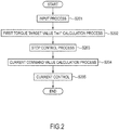
- FIG. 2 is a flow chart showing the flow of a motor current control process performed by the motor controller 2.
- Step S201 signals indicating the vehicle states are input.
- the vehicle speed V (km/h), the accelerator pedal opening AP (%), the rotor phase ⁇ (rad) of the electric motor 4, a rotation speed Nm (rpm) of the electric motor 4, the three-phase alternating currents iu, iv and iw flowing in the electric motor 4, and a direct-current voltage value Vdc (V) between the battery 1 and the inverter 3 are input.
- the vehicle speed V (km/h) is obtained by an unillustrated vehicle speed sensor or through communication by another controller.
- a vehicle speed v (m/s) may be obtained by multiplying a rotor mechanical angular velocity com by a tire dynamic radius R and dividing the product by a gear ratio of a final gear, then the quotient is multiplied by 3600/1000 for unit conversion, thereby obtaining the vehicle speed V (km/h).
- the accelerator pedal opening AP (%) is obtained from an unillustrated accelerator pedal opening sensor or through communication from another controller such as an unillustrated vehicle controller.
- the rotor phase ⁇ (rad) of the electric motor 4 is obtained from the rotation sensor 6.
- the rotation speed Nm (rpm) of the electric motor 4 is obtained by dividing a rotor angular velocity ⁇ (electric angle) by a pole pair number P of the electric motor 4 to obtain the motor rotation speed ⁇ m (rad/ s), which is a mechanical angular velocity of the electric motor 4, and multiplying the obtained motor rotation speed ⁇ m by 60/(2 ⁇ ).
- the rotor angular velocity ⁇ is obtained by differentiating the rotor phase ⁇ .
- the currents iu, iv and iw (A) flowing in the electric motor 4 are obtained from the current sensor 7.
- the direct-current voltage value Vdc (V) is obtained from a voltage sensor (not shown) provided in a direct-current power supply line between the battery 1 and the inverter 3 or a power supply voltage value transmitted from a battery controller (not shown).
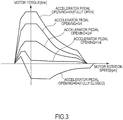
- a first torque target value Tm1* is set. Specifically, the first torque target value Tm1* is set on the basis of the accelerator pedal opening AP and the motor rotation speed ⁇ m input in Step S201 by referring to an accelerator pedal opening-torque table shown in FIG. 3 .
- the control device for electric motor vehicle in the present embodiment is applicable to a vehicle capable of controlling the acceleration/deceleration and the stop of the vehicle only by the operation of an accelerator pedal.
- a motor torque is set to increase a motor regeneration amount when the accelerator pedal opening is 0 (fully closed) in the accelerator pedal opening-torque table shown in FIG. 3 .
- the accelerator pedal opening-torque table is not limited to the one shown in FIG. 3 .
- Step S203 a stop control process is performed to execute such a control that the electric motor vehicle is stopped by the regenerative braking force of the electric motor 4. Specifically, a moment just before the electric motor vehicle stops is judged, the first torque target value Tm1* calculated in Step S202 is set as a motor torque command value Tm* before the moment just before the stop, and a second torque target value Tm2* which converges to a value balanced with a disturbance torque with a reduction in the motor rotation speed is set as the motor torque command value Tm* after the moment just before the stop.
- This second torque target value Tm2* is a positive torque on an uphill road, a negative torque on a downhill road and substantially zero on a flat road (a level road). In this way, a vehicle stopped state can be maintained regardless of a gradient of a road surface as described later. The detail of the stop control process is described later.
- Step S204 a d-axis current target value id* and a q-axis current target value iq* are obtained on the basis of the motor torque target value Tm* calculated in Step S203, the motor rotation speed ⁇ m and the direct-current voltage value Vdc.
- a table defining a relationship of the d-axis current target value id* and the q-axis current target value iq* with the torque command value, the motor rotation speed and the direct-current voltage value is prepared in advance and the d-axis current target value id* and the q-axis current target value iq* are obtained by referring to this table.
- Step S205 a current control is executed to match a d-axis current id and a q-axis current iq with the d-axis current target value id* and the q-axis current target value iq* obtained in Step S204.
- the d-axis current id and the q-axis current iq are first obtained on the basis of the three-phase alternating current values iu, iv and iw input in Step S201 and the rotor phase ⁇ of the electric motor 4.
- d-axis and q-axis voltage command values vd, vq are calculated from deviations between the d-axis and q-axis current command values id*, iq* and the d-axis and q-axis currents id, iq. It should be noted that a non-interference voltage necessary to cancel out an interference voltage between d-q orthogonal coordinate axes may be added to the calculated d-axis and q-axis voltage command values vd, vq.
- FIG. 4 is a diagram modeling a drive force transmission system of the vehicle and each parameter in FIG. 4 is as below.
- the transmission characteristic Gp(s) constitutes a transmission characteristic of (second order) / (third order) as shown in the following equation (9).
- the transmission characteristic Gp(s) is derived on the basis of a vehicle model shown in FIG. 4 .
- a 1 ' and b 0 ' in equation (9) are used as coefficients of the simplified vehicle model Gp'(s) in the present embodiment, a 1 and b 0 in equation (6) may be used instead of a 1 ' and b 0 '.
- FIG. 5 is a block diagram for realizing the stop control process.
- FIG. 5 shows a disturbance torque estimator 510, a gain setter 520, a motor rotation speed estimator 530, an F/B torque setter 540, an F/F torque setter 550, an adder 560, a subtractor 570, a just-before-stop judgment torque setter 580 and a torque comparator 590.
- Feedback is written as "F/B” and feedforward is written as "F/F” below.
- the disturbance torque estimator 510 estimates a disturbance torque applied to the electric motor 4 from the electric motor vehicle. It should be noted that the estimated value of the disturbance torque is referred to as a "disturbance torque estimated value Td" below.
- the disturbance torque estimator 510 calculates the disturbance torque estimated value Td on the basis of the detected motor rotation speed ⁇ m and motor torque command value Tm*. Then, the disturbance torque estimator 510 outputs the disturbance torque estimated value Td to the subtractor 570 and the gain setter 520.
- FIG. 6 is a block diagram showing a method for calculating the disturbance torque estimated value Td on the basis of the motor rotation speed ⁇ m and the motor torque command value Tm*.
- a control block 511 functions as a filter having a transmission characteristic H(s)/Gp(s) and calculates a first motor torque estimated value by filtering the input motor rotation speed ⁇ m.
- Gp(s) is the vehicle model of the transmission characteristic of the torque input to the vehicle and the motor rotation speed
- H(s) is a low-pass filter having such a transmission characteristic that a difference between the denominator degree and the numerator degree thereof is not smaller than a difference between the denominator degree and the numerator degree of Gp(s).
- a control block 512 functions as a low-pass filter having the transmission characteristic H(s) and calculates a second motor torque estimated value by filtering the input motor torque command value Tm*.
- the subtractor 513 calculates the disturbance torque estimated value by subtracting the second motor torque estimated value from the first motor torque estimated value.
- the disturbance torque is estimated by an disturbance observer as shown in FIG. 6 in the present embodiment, it may be estimated using a meter such as a vehicle longitudinal G sensor.
- the first motor torque estimated value is calculated by inputting the motor rotation speed ⁇ m to the filter having the transmission characteristic H(s)/Gp(s) composed of the model Gp(s) and such a transmission characteristic H(s) that the difference between the denominator degree and the numerator degree thereof is not smaller than a difference between the denominator degree and the numerator degree of the model Gp(s).
- the motor torque command value Tm* is input to the filter having the transmission characteristic H(s) to calculate the second motor torque estimated value, and the disturbance torque estimated value Td is obtained by calculating a deviation between the first motor torque estimated value and the second motor torque estimated value. In this way, the disturbance torque estimated value Td can be accurately obtained.
- the gain setter 520 adjusts a gain of a motor rotation speed F/B torque T ⁇ for generating a regenerative braking force of the electric motor 4 so as to reduce rollover occurring on an uphill road just before the vehicle stops.
- a feedforward torque (F/F torque) is added to the motor rotation speed F/B torque T ⁇ for a smooth deceleration without oscillating the torque of the electric motor 4 just before the vehicle stops.
- the gain setter 520 sets an F/F gain K2 for adjusting the F/F torque on the basis of the disturbance torque estimated value Td calculated in the disturbance torque estimator 510 when it is judged in Step S203 that the electric motor vehicle stops shortly. It should be noted that judgment as to whether or not the electric motor vehicle stops shortly is made by the torque comparator 590 to be described later.
- FIG. 7 is a diagram showing a method for calculating the F/F gain K2 on the basis of the disturbance torque estimated value Td.
- the gain setter 520 includes a calculator 521 for converting the disturbance torque estimated value Td into the F/F gain K2.
- An F/F gain map is stored in the calculator 521 in advance.
- the F/F gain map is a so-called gain scheduling map and the value of the F/F gain K2 is associated with each disturbance torque estimated value Td.
- the gain setter 520 calculates the F/F gain K2 corresponding to the disturbance torque estimated value Td by referring to the F/F gain map when it is judged that the electric motor vehicle stops shortly.
- FIG. 8 is a diagram showing an F/F gain map 522 retained in the calculator 521.
- a horizontal axis represents the disturbance torque estimated value Td and the vertical axis represents the magnitude of the F/F gain K2.
- the F/F gain K2 is set at a constant reference value Gd when the disturbance torque estimated value Td is not larger than zero, i.e. on a downhill road or a flat road.
- the absolute value of the F/F gain K2 is made smaller than on downhill and flat roads to reduce the regenerative braking force of the electric motor 4 when the vehicle stops on an uphill road.
- the F/F gain K2 becomes larger than the reference value Gd as the disturbance torque estimated value Td becomes larger than zero.
- the F/F gain K2 is fixed at the upper limit value Gu.
- the calculator 521 judges whether or not the road surface is uphill on the basis of the disturbance torque estimated value Td by referring to the F/F gain map 522. If the road surface is judged to be uphill, the absolute value of the F/F gain K2 is reduced to make the regenerative braking force of the electric motor 4 smaller than on the downhill road.
- the calculator 521 fixes the calculated value of the F/F gain K2 and continues to output it to the F/F torque setter 550 until the electric motor vehicle stops after calculation. Specifically, the disturbance torque estimated value Td when it was judged that the vehicle would stop shortly is output to the F/F torque setter 550 until the vehicle stops.
- the motor rotation speed estimator 530 estimates the rotation speed of the electric motor 4 by an open loop.
- the estimated value of the rotation speed of the electric motor 4 is referred to as a "motor rotation speed estimated value”.
- FIG. 9 is a diagram showing a method for calculating the motor rotation speed estimated value according to the state of the electric motor vehicle.
- the motor rotation speed estimator 530 includes a motor torque estimation unit 531, a motor rotation speed calculation unit 532 and a low-pass filter 533.
- the motor torque estimation unit 531 calculates the motor torque estimated value by multiplying the motor rotation speed estimated value by a predetermined gain (hereinafter, referred to as a "total gain") Kvref used in the calculation of the motor rotation speed F/B torque.
- a predetermined gain hereinafter, referred to as a "total gain” Kvref used in the calculation of the motor rotation speed F/B torque.
- the total gain Kvref is a predetermined negative (minus) value for smoothly decelerating the electric motor vehicle while suppressing a braking distance, and appropriately set, for example, by experimental data.
- the motor torque estimation unit 531 outputs the motor torque estimated value to the motor rotation speed calculation unit 532. Since the motor torque estimated value works as a viscous (damper) element for a dynamic characteristic from the motor torque estimated value to the motor rotation speed estimated value, the motor rotation speed estimated value smoothly (asymptotically) converges to zero just before the vehicle stops. This enables the realization of a smooth vehicle stop free from any shock to longitudinal acceleration.
- the motor rotation speed calculation unit 532 converts the motor torque estimated value into the motor rotation speed estimated value on the basis of the vehicle model Gp(s) shown in equation (6).
- the simplified vehicle model Gp'(s) shown in equation (10) is used instead of the vehicle model Gp(s).
- the motor rotation speed calculation unit 532 calculates the motor rotation speed estimated value on the basis of the simplified vehicle model Gp'(s) by inputting the motor torque estimated value to the simplified vehicle model Gp'(s).
- the motor rotation speed calculation unit 532 outputs the motor rotation speed estimated value based on the simplified vehicle model Gp'(s) to the motor torque estimation unit 531 and the low-pass filter 533.
- the low-pass filter 533 is a filter having a transmission characteristic Hc(s) set to complement the simplified vehicle model Gp'(s).
- the transmission characteristic Hc(s) is set on the basis of simulation, experimental data or the like. Specifically, a time constant of the transmission characteristic Hc(s) is adjusted so that the convergence of the motor rotation speed estimated value input to the F/F torque setter 550 is equal to that of the motor rotation speed ⁇ m in a state where the total gain Kvref is smaller than zero.
- the motor rotation speed estimated value is calculated on the basis of the vehicle model Gp(s) and the motor torque estimated value converges to zero with a reduction in the motor rotation speed estimated value.
- the motor rotation speed estimated value can be obtained just before the electric motor vehicle stops.
- the motor rotation speed calculation unit 532 initializes the simplified vehicle model Gp'(s) on the basis of the motor rotation speed ⁇ m if it is judged by the torque comparator 590 to be described later that the electric motor vehicle is not just before the stop and travels some time before that.
- the simplified vehicle model Gp'(s) is composed of constants a1' and b0' uniquely determined by design values of the vehicle and an integrator. If it is judged that the electric motor vehicle stops shortly, the simplified vehicle model Gp'(s) is initialized by setting an initial value of the above integrator as the motor rotation speed ⁇ m.
- the F/B torque setter 540 calculates an F/B torque for smoothly decelerating the electric motor vehicle by the regenerative braking force of the electric motor 4 on the basis of the detected motor rotation speed ⁇ m.
- FIG. 10 is a diagram showing a method for calculating the F/B torque on the basis of the motor rotation speed ⁇ m.
- the F/B torque setter 540 includes a multiplier 541 for converting the motor rotation speed com into the F/B torque.
- the multiplier 541 calculates the F/B torque by multiplying the motor rotation speed ⁇ m by an F/B gain K1 determined to distribute the regenerative braking force of the electric motor 4.
- the F/B gain K1 is set in a direction to weaken the regenerative braking force with respect to the total gain Kvref. Specifically, the F/B gain K1 is set at a value smaller than zero and larger than the total gain Kvref.
- the F/B gain K1 is a value obtained by subtracting the F/F gain K2 from the total gain Kvref. Specifically, the F/B gain K1 is set at a value obtained by subtracting the reference value Gd of the F/F gain on the downhill road from the total gain Kvref.
- the F/B torque setter 540 is described to calculate the F/B torque by multiplying the motor rotation speed ⁇ m by the F/B gain K1
- the F/B torque may be calculated using a regenerative torque table defining a regenerative torque in relation to the motor rotation speed ⁇ m, an attenuation rate table storing an attenuation rate of the motor rotation speed ⁇ m in advance or the like.
- the F/F torque setter 550 calculates the F/F torque on the basis of the motor rotation speed estimated value output from the motor rotation speed estimator 530. A shortage of the regenerative braking force caused by the F/B torque is compensated for by the F/F torque just before the vehicle stops.
- FIG. 11 is a diagram showing a method for calculating the F/F torque on the basis of the motor rotation speed ⁇ m.
- the F/F torque setter 550 includes a multiplier 551 for converting the motor rotation speed estimated value into the F/F torque.
- the multiplier 551 calculates the F/F torque by multiplying the motor rotation speed ⁇ m by the F/F gain K2 output from the gain setter 520.
- the F/F torque setter 550 is described to calculate the F/F torque by multiplying the motor rotation speed estimated value by the F/F gain K2 in the present embodiment, the F/F torque may be calculated using the regenerative torque table defining a regenerative torque in relation to the motor rotation speed ⁇ m, the attenuation rate table storing an attenuation rate of the motor rotation speed estimated value in advance or the like.
- the adder 560 calculates the motor rotation speed F/B torque T ⁇ by adding the F/B torque calculated in the F/B torque setter 540 and the F/F torque calculated in the F/F torque setter 550. By adding the F/F torque, it is possible to suppress the oscillation of the torque of the electric motor 4 while suppressing an increase of the braking distance.
- the subtractor 570 calculates the second torque target value Tm2* for smoothly stopping the vehicle regardless of the gradient of the road surface by calculating a deviation between the motor rotation speed F/B torque T ⁇ calculated in the adder 560 and the disturbance torque estimated value Td calculated in the disturbance torque estimator 510.
- the just-before-stop judgment torque setter 580 calculates a just-before-stop judgment torque on the basis of the detected motor rotation speed ⁇ m.
- FIG. 12 is a block diagram showing a method for calculating the just-before-stop judgment torque on the basis of the motor rotation speed com.
- the just-before-stop judgment torque setter 580 includes a multiplier 581 for converting the motor rotation speed ⁇ m into the just-before-stop judgment torque.
- the multiplier 581 calculates the just-before-stop judgment torque by multiplying the motor rotation speed ⁇ m by the total gain Kvref.
- the torque comparator 590 compares the magnitude of the first torque target value Tm1* calculated in Step S202 and that of the just-before-stop judgment torque calculated in the just-before-stop judgment torque setter 580.
- the just-before-stop judgment torque is smaller than the first torque target value Tm1* during the travel of the vehicle and becomes larger than the first torque target value Tm1* when the vehicle decelerates and stops shortly (vehicle speed is not higher than a predetermined vehicle speed).
- the torque comparator 590 judges that the vehicle stops shortly and switches the motor torque command value Tm* from the first torque target value Tm1* to the second torque target value Tm2* when the just-before-stop judgment torque becomes larger than the first torque target value Tm1*.
- the torque comparator 590 sets the first torque target value Tm1* as the motor torque command value Tm* by determining that a moment just before the vehicle stops has not been reached yet if the just-before-stop judgment torque is judged to be equal to or smaller than the firsts torque target value Tm1*.
- the torque comparator 590 judges that the vehicle stops shortly and switches the motor torque command value Tm* from the first torque target value Tm1* to the second torque target value Tm2* if the just-before-stop judgment torque is judged to be larger than the first torque target value Tm1*.
- the second torque target value Tm2* is a positive torque on an uphill road, a negative torque on a downhill road and converges substantially to zero on a flat road to maintain the vehicle stopped state.
- the torque comparator 590 switches a judgement flag thereof from an L (Low) level to an H (High) level when judging that the vehicle stops shortly. Then, the gain setter 520 calculates the F/F gain K2 on the basis of the disturbance torque estimated value Td and sets the calculated value in the F/F torque setter 550 when the judgment flag is set to the H level.
- the regenerative braking force of the electric motor 4 is reduced by setting the F/F gain K2 at a value larger than the reference value Gd as shown in FIG. 8 .
- G jerk caused by the backlash of the gear and the like can be suppressed when the vehicle stops on the uphill road.
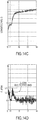
- FIGS. 13A to 13D are time charts when the stop control process is performed without changing the total gain Kvref on an uphill road.
- FIGS. 13A to 13D respectively show changes of the motor torque command value Tm*, the motor rotation speed ⁇ m, the longitudinal acceleration (G) and the G jerk until the electric motor vehicle stops after starting to decelerate on the uphill road, wherein a horizontal axis is a time axis common to each other.
- a target value based on the disturbance torque i.e. a value obtained by reversing the sign of the disturbance torque estimated value Td is shown by a broken line in FIG. 13A .
- the G jerk represents a change rate of longitudinal G per unit time.
- rollover in the front-back direction of the vehicle occurs due to the pitching of the gear.
- a driver more easily feels rollover as the G jerk becomes larger.
- the electric motor vehicle is judged to stop shortly by the torque comparator 590 and the stop control process is performed. Since this causes the second torque target value Tm2* to be set as the motor torque command value Tm*, the electric motor vehicle brakes according to the second torque target value Tm2*.
- the total gain Kvref is a fixed value regardless of the disturbance torque command value Td.
- the stopped state of the electric motor vehicle is held since the second torque target value Tm2* is set at the value obtained by reversing the sign of the disturbance torque estimated value Td.
- FIGS. 14A to 14D are time charts showing an example of control results by the control device for electric motor vehicle in the one embodiment.
- FIGS. 14A to 14D respectively show changes of the motor torque command value Tm*, the motor rotation speed ⁇ m, the longitudinal acceleration (G) and the G jerk, wherein a horizontal axis is a time axis common to each other.
- the electric motor vehicle is judged to stop shortly by the torque comparator 590 and the stop control process is performed. Since this causes the second torque target value Tm2* to be set as the motor torque command value Tm*, the electric motor vehicle brakes according to the second torque target value Tm2*.
- the disturbance torque estimated value Td when the vehicle is judged to stop shortly is a positive value and the second torque target value Tm2* is a positive value.
- the F/F gain K2 used in the calculation of the motor rotation speed F/B torque T ⁇ is set to make the regenerative braking force smaller than on flat and downhill roads when the disturbance torque command value Td at the time of judging that the vehicle stops shortly is larger than zero, i.e. on the uphill road as shown in FIG. 8 .
- the stopped state of the electric motor vehicle is held since the second torque target value Tm2* is set at the value obtained by reversing the sign of the disturbance torque estimated value Td.
- the overshoot of the longitudinal G just before the vehicle stops can be suppressed by reducing the total gain Kvref used in the stop control process according to the disturbance torque estimated value on the uphill road crossing over the region having a strong nonlinearity caused by the backlash of the gear and the like. Since the G jerk is suppressed in this way, the rollover felt by the driver can be suppressed.
- the F/F gain K2 out of the total gain Kvref is changed on the basis of the disturbance torque estimated value Td in the above description
- the F/B gain K1 may be changed on the basis of the disturbance torque estimated value Td.
- An example of setting the F/B gain K1 on the basis of the disturbance torque estimated value Td is described below.
- FIG. 15 is a block diagram for realizing the stop control process when the motor rotation speed F/B torque T ⁇ is set as the second torque target value Tm2* without using the F/F torque in conjunction.
- the same constituent elements as those shown in FIG. 5 are denoted by the same reference signs.
- the second torque target value Tm2* can be moderately changed by reducing a degree of change of the motor rotation speed F/B torque T ⁇ on the uphill road.
- the second torque target value Tm2* set as the motor torque command value Tm* more moderately changes than on the downhill road by setting the total gain Kvref as the F/B gain K1 and setting the F/B gain K1 on the uphill road as shown in FIG. 16 .
- control device for electric motor vehicle in the one embodiment is a control device for electric motor vehicle using the electric motor 4 as a traveling drive source and configured to decelerate by the regenerative braking force of the electric motor 4 when an accelerator operation amount decreases or becomes zero, detects the accelerator operation amount, calculates the motor torque command value and controls the electric motor 4 on the basis of the calculated motor torque command value.
- control device detects the motor rotation speed ⁇ m as a speed parameter proportional to the traveling speed of the electric motor vehicle, calculates the motor rotation speed F/B torque T ⁇ for stopping the electric motor vehicle on the basis of the motor rotation speed ⁇ m and estimates the disturbance torque acting on the electric motor 4 from the electric motor vehicle.
- the motor torque command value Tm* is converged to the disturbance torque on the basis of the motor rotation speed F/B torque T ⁇ as the speed parameter proportional to the traveling speed is reduced.
- the vehicle smoothly stops also on slopes and the vehicle stopped state can be held without requiring foot braking. Further, since the disturbance torque is estimated to be zero on the flat road, the vehicle can smoothly stop and the vehicle stopped state can be held without requiring foot braking on the flat road.
- the disturbance torque mentioned here is a torque value necessary to cancel the disturbance torque and a target value obtained by reversing the sign of the estimated value Td calculated in the disturbance torque estimator 510 in FIG. 5 .
- the disturbance torque is the second torque target value Tm2* when the motor rotation speed F/B torque T ⁇ is zero.
- the degree of change of the motor rotation speed F/B torque T ⁇ i.e. a response characteristic is adjusted according to the disturbance torque.
- rollover in the front-back direction of the vehicle due to the pitching of the gear is larger than in the case of stopping the vehicle on the flat road.
- the region having a strong nonlinearity due to the backlash of the gear and the like is crossed over on the uphill road.
- the vehicle can be decelerated up to the vehicle stopped state even without using the braking force by mechanical braking means such as a foot brake, the regenerative operation of the electric motor 4 is possible also just before the vehicle stops and electric power consumption can be improved. Furthermore, since the acceleration/deceleration and the stop of the vehicle can be realized only by the accelerator operation, it is not necessary to switchingly depress the accelerator pedal and a brake pedal and burdens on the driver can be reduced.
- any driver can realize a smooth deceleration and stop only by the accelerator operation as described above.
- the motor rotation speed F/B torque T ⁇ is calculated by multiplying the motor rotation speed ⁇ m by the predetermined total gain Kvref for stopping the electric motor vehicle. Then, the total gain Kvref is changed on the basis of the disturbance torque.
- the motor rotation speed F/B torque T ⁇ can be moderately changed.
- the degree of change of the motor rotation speed F/B torque T ⁇ can be adjusted by a simple technique without performing a complicated arithmetic processing using an adjustment table or the like showing a relationship of the motor rotation speed ⁇ m and the motor rotation speed F/B torque T ⁇ .
- the control device for electric motor vehicle in the one embodiment sets the total gain Kvref to make the regenerative braking force smaller than on the flat and downhill roads when judging on the basis of the disturbance torque that the road surface is uphill. Since this makes a change of the motor torque command value Tm* moderate in the case of stopping the vehicle on the uphill road, the G jerk can be suppressed.
- the motor rotation speed is estimated and the F/F torque for compensating for the F/B torque is calculated on the basis of the estimated motor rotation speed estimated value.
- the motor torque command value Tm* is converged to the disturbance torque on the basis of the motor rotation speed F/B torque T ⁇ including the F/B torque and the F/F torque with a reduction in the traveling speed.
- the F/B torque is calculated by multiplying the motor rotation speed ⁇ m by the predetermined gain K1 for distributing the regenerative braking force of the motor and the F/F torque is calculated by multiplying the motor rotation speed estimated value by the predetermined gain K2 set according to the gain K1.
- the motor rotation speed F/B torque T ⁇ obtained by adding the F/F torque to the F/B torque is set as the motor torque command value Tm*.
- the gain K2 is changed on the basis of the disturbance torque. If the gain K1 is reduced on the uphill road on the basis of the disturbance torque, the responsiveness of the electric motor 4 when the disturbance torque such as a gradient change is input is degraded. On the contrary, if the gain K1 is increased, the stability of an F/B system is reduced and the motor torque becomes oscillatory.
- the absolute value of the gain K2 is set to be small to make the regenerative braking force of the electric motor 4 smaller than on the flat road when the road surface is judged to be uphill on the basis of the disturbance torque. In this way, it is possible to suppress the degradation of the responsiveness of the electric motor 4 for disturbances while suppressing the rollover in the front-back direction of the electric motor vehicle due to the backlash of the gear in the case of stopping the vehicle on the uphill road.
- the first torque target value Tm1* is calculated on the basis of vehicle information
- the second torque target value Tm2* that converges to the disturbance torque with a reduction in the motor rotation speed ⁇ m is calculated
- the just-before-stop judgment torque is calculated by multiplying the motor rotation speed ⁇ m by the total gain Kvref and the magnitude of the first torque target value Tm1* and that of the just-before-stop judgment torque are compared. If the just-before-stop judgment torque is judged to be larger than the first torque target value Tm1*, it is judged that the vehicle stops shortly and the motor torque command value Tm* is switched from the first torque target value Tm1* to the second torque target value Tm2*.
- the gain of the motor rotation speed F/B torque T ⁇ is set on the basis of the disturbance torque and the set gain is maintained until the vehicle stops.
- the present invention is not limited to the one embodiment described above.
- the example of detecting the motor rotation speed as the speed parameter proportional to the traveling speed of the electric motor vehicle is described in the above description.
- a wheel speed, a vehicle body speed, a rotation speed of the drive shaft and the like are also proportional to the traveling speed of the vehicle, they can be used as speed parameters.
- the wheel speed may be detected as the speed parameter proportional to the traveling speed of the electric motor vehicle
- the F/B torque may be calculated on the basis of the wheel speed
- the wheel speed may be estimated according to the state of the electric motor vehicle and the F/F torque may be calculated based on the estimated value.
- the motor torque command value Tm* is converged to zero on the basis of the F/B torque and the F/F torque as the traveling speed obtained by the wheel speed is reduced. Even if the speed parameter other than the motor rotation speed is used in this way, effects similar to those of the present embodiment are obtained.
- the torque comparator 590 is described to determine that the vehicle stops shortly and switch the motor torque command value Tm* from the first torque target value Tm1* to the second torque target value Tm2* when judging that the just-before-stop judgment torque is larger than the first torque target value Tm1*. However, the torque comparator 590 may compare the magnitudes of the first and second torque target values Tm1*, Tm2* and set the larger value as the motor torque command value Tm*.
Landscapes
- Engineering & Computer Science (AREA)
- Power Engineering (AREA)
- Transportation (AREA)
- Mechanical Engineering (AREA)
- Life Sciences & Earth Sciences (AREA)
- Sustainable Development (AREA)
- Sustainable Energy (AREA)
- Electric Propulsion And Braking For Vehicles (AREA)
Description
- The present invention relates to a control device for electric motor vehicle and a control method for electric motor vehicle.
- Conventionally, a regenerative brake control device for electric vehicle is known which is provided with setting means capable of arbitrarily setting a regenerative braking force of a motor and regenerates the motor by the regenerative braking force set by the setting means (see
JP8-79907A JP H09 130911 A WO 2013/115042 A1 discloses a regenerative brake control device for an electrically driven vehicle provided with an electric motor connected to a driving wheel, an electric motor controller for controlling motoring and regenerating of an electric motor, and a steering switch for setting a regeneration amount in accordance with the driver's operations. In this electrically driven vehicle system wherein a regeneration amount is changeable according to a driver's intent, the electric motor controller includes a regeneration command torque limiting means for limiting a regeneration amount such that the regeneration amount decreases as the vehicle traveling speed decreases when a vehicle is coming to a stop. - However, if the regenerative braking force set by the setting means is large, a problem of generating vibration in a front-back direction of a vehicle body arises when the electric vehicle is decelerated by the set regenerative braking force and the speed becomes 0.
- The present invention aims to provide a technology for suppressing the generation of vibration in a front-back direction of a vehicle body in stopping an electric motor vehicle with a regenerative braking force.
- This aim is achieved by the combination of features of the independent claims. According to one aspect of the present invention, a control device for electric motor vehicle uses a motor as a traveling drive source and is configured to decelerate by a regenerative braking force of the motor when an accelerator operation amount decreases or becomes zero. The control device detects the accelerator operation amount, calculates a motor torque command value, and controls the motor on the basis of the motor torque command value calculated. The control device detects a speed parameter proportional to a traveling speed of the electric motor vehicle and calculates a feedback torque for stopping the electric motor vehicle on the basis of the speed parameter detected. The control device also estimates a disturbance torque acting on the motor and converges, as the speed parameter is reduced, the motor torque command value to the disturbance torque on the basis of the feedback torque when the accelerator operation amount decreases or becomes zero and when the electric motor vehicle stops shortly. The control device adjusts the feedback torque according to the disturbance torque.
-
-
FIG. 1 is a block diagram showing a main configuration of an electric vehicle with a control device for electric vehicle in one embodiment, -
FIG. 2 is a flow chart showing the flow of a motor current control process performed by a motor controller, -
FIG. 3 is a graph showing an example of an accelerator pedal opening-torque table, -
FIG. 4 is a diagram modeling a drive force transmission system of the vehicle, -
FIG. 5 is a block diagram for realizing a stop control process, -
FIG. 6 is a block diagram showing a method for calculating a disturbance torque estimated value on the basis of a motor rotation speed and a motor torque command value, -
FIG. 7 is a diagram showing a method for calculating an F/F gain on the basis of the disturbance torque estimated value, -
FIG. 8 is a conceptual diagram showing an example of an F/F gain map, -
FIG. 9 is a diagram showing a method for calculating a motor rotation speed estimated value, -
FIG. 10 is a diagram showing a method for calculating an F/B torque on the basis of the detected motor rotation speed, -
FIG. 11 is a diagram showing a method for calculating an F/F torque on the basis of the motor rotation speed estimated value, -
FIG. 12 is a block diagram showing a method for calculating a just-before-stop judgment torque on the basis of the motor rotation speed, -
FIG. 13A is a chart showing a motor torque command value when the stop control process is performed without changing a total gain on an uphill road, -
FIG. 13B is a chart showing the motor rotation speed by the stop control process performed inFIG. 13A , -
FIG. 13C is a chart showing longitudinal acceleration by the stop control process performed inFIG. 13A , -
FIG. 13D is a chart showing G jerk by the stop control process performed inFIG. 13A , -
FIG. 14A is a chart showing the motor torque command value out of control results by the control device for electric motor vehicle in the one embodiment, -
FIG. 14B is a chart showing the motor rotation speed out of the control results, -
FIG. 14C is a chart showing the longitudinal acceleration by the control results, -
FIG. 14D is a chart showing the G jerk by the control results, -
FIG. 15 is a block diagram for realizing the stop control process when a motor rotation speed F/B torque is set as a second torque target value Tm2* without using the F/F torque in conjunction, and -
FIG. 16 is a conceptual diagram showing an example of an F/B gain map. -
FIG. 1 is a block diagram showing a main configuration of an electric vehicle with a control device for electric motor vehicle in one embodiment. The control device for electric motor vehicle of the present invention includes an electric motor as part or the entirety of a drive source of the vehicle and is applicable to an electric motor vehicle capable of traveling by a drive force of the electric motor. Electric motor vehicles include not only electric vehicles, but also hybrid vehicles and fuel cell vehicles. Particularly, the control device for electric motor vehicle in the present embodiment can be applied to a vehicle capable of controlling the acceleration/deceleration and the stop of the vehicle only by the operation of an accelerator pedal. In this vehicle, a driver depresses the accelerator pedal during acceleration and reduces or zeroes the amount of depression of the accelerator pedal during deceleration or during stop. - A motor controller 2 has signals indicating vehicle states such as a vehicle speed (traveling speed of the electric motor vehicle) V, an accelerator pedal opening AP, a rotor phase α of an electric motor (three-phase AC motor) 4, currents iu, iv and iw of the
electric motor 4 input thereto in the form of digital signals, and generates PWM signals for controlling theelectric motor 4 on the basis of the input signals. Further, the motor controller 2 generates a drive signal for aninverter 3 according to the generated PWM signals. - The
inverter 3 includes, for example, two switching elements (e.g. power semiconductor elements such as IGBTs or MOS-FETs) for each phase, converts a direct current supplied from abattery 1 into an alternating current by turning on and off the switching elements according to the drive signal, and causes a desired current to flow into theelectric motor 4. - The
electric motor 4 generates a drive force by the alternating current supplied from theinverter 3 and transmits the drive force to left andright drive wheels speed reducer 5 and adrive shaft 8. Further, when being rotated following the rotation of thedrive wheels electric motor 4 generates a regenerative drive force, thereby collecting kinetic energy of the vehicle as electrical energy. In this case, theinverter 3 converts an alternating current generated during the regenerative operation of theelectric motor 4 into a direct current and supplies it to thebattery 1. - A current sensor 7 detects three-phase alternating currents iu, iv and iw flowing in the
electric motor 4. However, since the sum of the three-phase alternating currents is 0, the currents of arbitrary two phases may be detected and the current of the remaining one phase may be obtained by calculation. - A
rotation sensor 6 is, for example, a resolver or an encoder and detects the rotor phase α of theelectric motor 4. -
FIG. 2 is a flow chart showing the flow of a motor current control process performed by the motor controller 2. - In Step S201, signals indicating the vehicle states are input. Here, the vehicle speed V (km/h), the accelerator pedal opening AP (%), the rotor phase α (rad) of the
electric motor 4, a rotation speed Nm (rpm) of theelectric motor 4, the three-phase alternating currents iu, iv and iw flowing in theelectric motor 4, and a direct-current voltage value Vdc (V) between thebattery 1 and theinverter 3 are input. - The vehicle speed V (km/h) is obtained by an unillustrated vehicle speed sensor or through communication by another controller. Alternatively, a vehicle speed v (m/s) may be obtained by multiplying a rotor mechanical angular velocity com by a tire dynamic radius R and dividing the product by a gear ratio of a final gear, then the quotient is multiplied by 3600/1000 for unit conversion, thereby obtaining the vehicle speed V (km/h).
- The accelerator pedal opening AP (%) is obtained from an unillustrated accelerator pedal opening sensor or through communication from another controller such as an unillustrated vehicle controller.
- The rotor phase α (rad) of the
electric motor 4 is obtained from therotation sensor 6. The rotation speed Nm (rpm) of theelectric motor 4 is obtained by dividing a rotor angular velocity ω (electric angle) by a pole pair number P of theelectric motor 4 to obtain the motor rotation speed ωm (rad/ s), which is a mechanical angular velocity of theelectric motor 4, and multiplying the obtained motor rotation speed ωm by 60/(2π). The rotor angular velocity ω is obtained by differentiating the rotor phase α. - The currents iu, iv and iw (A) flowing in the
electric motor 4 are obtained from the current sensor 7. - The direct-current voltage value Vdc (V) is obtained from a voltage sensor (not shown) provided in a direct-current power supply line between the
battery 1 and theinverter 3 or a power supply voltage value transmitted from a battery controller (not shown). - In Step S202, a first torque target value Tm1* is set. Specifically, the first torque target value Tm1* is set on the basis of the accelerator pedal opening AP and the motor rotation speed ωm input in Step S201 by referring to an accelerator pedal opening-torque table shown in
FIG. 3 . As described above, the control device for electric motor vehicle in the present embodiment is applicable to a vehicle capable of controlling the acceleration/deceleration and the stop of the vehicle only by the operation of an accelerator pedal. To enable the vehicle to stop at least by fully closing the accelerator pedal, a motor torque is set to increase a motor regeneration amount when the accelerator pedal opening is 0 (fully closed) in the accelerator pedal opening-torque table shown inFIG. 3 . Specifically, when the motor rotation speed is positive and at least the accelerator pedal opening is 0 (fully closed), a negative motor torque is set so that a regenerative braking force works. However, the accelerator pedal opening-torque table is not limited to the one shown inFIG. 3 . - In Step S203, a stop control process is performed to execute such a control that the electric motor vehicle is stopped by the regenerative braking force of the
electric motor 4. Specifically, a moment just before the electric motor vehicle stops is judged, the first torque target value Tm1* calculated in Step S202 is set as a motor torque command value Tm* before the moment just before the stop, and a second torque target value Tm2* which converges to a value balanced with a disturbance torque with a reduction in the motor rotation speed is set as the motor torque command value Tm* after the moment just before the stop. This second torque target value Tm2* is a positive torque on an uphill road, a negative torque on a downhill road and substantially zero on a flat road (a level road). In this way, a vehicle stopped state can be maintained regardless of a gradient of a road surface as described later. The detail of the stop control process is described later. - In Step S204, a d-axis current target value id* and a q-axis current target value iq* are obtained on the basis of the motor torque target value Tm* calculated in Step S203, the motor rotation speed ωm and the direct-current voltage value Vdc. For example, a table defining a relationship of the d-axis current target value id* and the q-axis current target value iq* with the torque command value, the motor rotation speed and the direct-current voltage value is prepared in advance and the d-axis current target value id* and the q-axis current target value iq* are obtained by referring to this table.
- In Step S205, a current control is executed to match a d-axis current id and a q-axis current iq with the d-axis current target value id* and the q-axis current target value iq* obtained in Step S204. To this end, the d-axis current id and the q-axis current iq are first obtained on the basis of the three-phase alternating current values iu, iv and iw input in Step S201 and the rotor phase α of the
electric motor 4. Subsequently, d-axis and q-axis voltage command values vd, vq are calculated from deviations between the d-axis and q-axis current command values id*, iq* and the d-axis and q-axis currents id, iq. It should be noted that a non-interference voltage necessary to cancel out an interference voltage between d-q orthogonal coordinate axes may be added to the calculated d-axis and q-axis voltage command values vd, vq. - Subsequently, three-phase alternating-current voltage command values uv, vv and vw are obtained from the d-axis and q-axis voltage command values vd, vq and the rotor phase α of the
electric motor 4. Then, PWM signals tu (%), tv (%) and tw (%) are obtained from the obtained three-phase alternating-current voltage command values vu, vv and vw and the direct-current voltage value Vdc. By opening and closing the switching elements of theinverter 3 by the PWM signals tu, tv and tw obtained in this way, theelectric motor 4 can be driven with a desired torque instructed by the torque command value Tm*. - Here, before describing the stop control process performed in Step S203, a transmission characteristic Gp(s) from the motor torque Tm to the motor rotation speed ωm is described in the control device for electric motor vehicle in the present embodiment.
-
FIG. 4 is a diagram modeling a drive force transmission system of the vehicle and each parameter inFIG. 4 is as below. - Jm:
- inertia of electric motor
- Jw:
- inertia of drive wheels
- M:
- weight of vehicle
- Kd:
- torsional rigidity of drive system
- Kt:
- coefficient on friction between tires and road surface
- N:
- overall gear ratio
- r:
- load radius of tires
- ωm:
- angular velocity of electric motor
- Tm:
- torque target value
- Td:
- torque of drive wheels
- F:
- force applied to vehicle
- V:
- speed of vehicle
- ωw:
- angular velocity of drive wheels
- The following motion equations can be derived from
FIG. 4 . However, asterisk (*) attached to the right-upper corner of a symbol in equations (1) to (3) indicates a time differential.
[Equation 1]
[Equation 2]
[Equation 3]
[Equation 4]
[Equation 5]
- The transmission characteristic Gp(s) from the torque target value Tm to the motor rotation speed ωm of the
electric motor 4 obtained on the basis of the motion equations (1) to (5) is expressed by the following equation (6).
[Equation 6]
where each parameter in equation (6) is expressed by the following equations (7).
[Equations 7]
- The poles and zero point of the transmission function shown in equation (6) can be approximated to a transmission function of the following equation (8) and one pole and one zero point indicate values extremely close to each other. This is equivalent to that α and β of the following equation (8) indicate values extremely close to each other.
[Equation 8]
- Accordingly, by performing pole-zero cancellation (approximation to α = β) in equation (8), the transmission characteristic Gp(s) constitutes a transmission characteristic of (second order) / (third order) as shown in the following equation (9).
[Equation 9]
- In this way, the transmission characteristic Gp(s) is derived on the basis of a vehicle model shown in
FIG. 4 . By simplifying the vehicle model of the transmission characteristic Gp(s), a simplified vehicle model Gp'(s) is expressed by the following equation (10).
[Equation 10]
- It should be noted that although a1' and b0' in equation (9) are used as coefficients of the simplified vehicle model Gp'(s) in the present embodiment, a1 and b0 in equation (6) may be used instead of a1' and b0'.
- Next, the detail of the stop control process performed in Step S203 of
FIG. 2 is described.FIG. 5 is a block diagram for realizing the stop control process.FIG. 5 shows adisturbance torque estimator 510, again setter 520, a motorrotation speed estimator 530, an F/B torque setter 540, an F/F torque setter 550, anadder 560, asubtractor 570, a just-before-stopjudgment torque setter 580 and atorque comparator 590. Feedback is written as "F/B" and feedforward is written as "F/F" below. - The
disturbance torque estimator 510 estimates a disturbance torque applied to theelectric motor 4 from the electric motor vehicle. It should be noted that the estimated value of the disturbance torque is referred to as a "disturbance torque estimated value Td" below. Thedisturbance torque estimator 510 calculates the disturbance torque estimated value Td on the basis of the detected motor rotation speed ωm and motor torque command value Tm*. Then, thedisturbance torque estimator 510 outputs the disturbance torque estimated value Td to thesubtractor 570 and thegain setter 520. -
FIG. 6 is a block diagram showing a method for calculating the disturbance torque estimated value Td on the basis of the motor rotation speed ωm and the motor torque command value Tm*. - A
control block 511 functions as a filter having a transmission characteristic H(s)/Gp(s) and calculates a first motor torque estimated value by filtering the input motor rotation speed ωm. Gp(s) is the vehicle model of the transmission characteristic of the torque input to the vehicle and the motor rotation speed, and H(s) is a low-pass filter having such a transmission characteristic that a difference between the denominator degree and the numerator degree thereof is not smaller than a difference between the denominator degree and the numerator degree of Gp(s). - A
control block 512 functions as a low-pass filter having the transmission characteristic H(s) and calculates a second motor torque estimated value by filtering the input motor torque command value Tm*. - The
subtractor 513 calculates the disturbance torque estimated value by subtracting the second motor torque estimated value from the first motor torque estimated value. - It should be noted that although the disturbance torque is estimated by an disturbance observer as shown in
FIG. 6 in the present embodiment, it may be estimated using a meter such as a vehicle longitudinal G sensor. - Here, air resistance, a modeling error caused by a variation of a vehicle mass due to the number of passengers and load capacity, rolling resistance of the tires, gradient resistance of the road surface and the like can be thought as disturbances, but a disturbance factor dominant just before the vehicle stops is gradient resistance. Disturbance factors differ depending on driving conditions, but the disturbance factors described above can be collectively estimated since the
disturbance torque estimator 510 calculates the disturbance torque estimated value Td on the basis of the motor torque command value Tm*, the motor rotation speed ωm and the vehicle model Gp(s). This enables the realization of a smooth vehicle stop from deceleration under any driving condition. - As just described, in the
disturbance torque estimator 510, the first motor torque estimated value is calculated by inputting the motor rotation speed ωm to the filter having the transmission characteristic H(s)/Gp(s) composed of the model Gp(s) and such a transmission characteristic H(s) that the difference between the denominator degree and the numerator degree thereof is not smaller than a difference between the denominator degree and the numerator degree of the model Gp(s). Together with this, the motor torque command value Tm* is input to the filter having the transmission characteristic H(s) to calculate the second motor torque estimated value, and the disturbance torque estimated value Td is obtained by calculating a deviation between the first motor torque estimated value and the second motor torque estimated value. In this way, the disturbance torque estimated value Td can be accurately obtained. - Next, the configuration of the
gain setter 520 shown inFIG. 5 is described. - The
gain setter 520 adjusts a gain of a motor rotation speed F/B torque Tω for generating a regenerative braking force of theelectric motor 4 so as to reduce rollover occurring on an uphill road just before the vehicle stops. - In the present embodiment, a feedforward torque (F/F torque) is added to the motor rotation speed F/B torque Tω for a smooth deceleration without oscillating the torque of the
electric motor 4 just before the vehicle stops. - The
gain setter 520 sets an F/F gain K2 for adjusting the F/F torque on the basis of the disturbance torque estimated value Td calculated in thedisturbance torque estimator 510 when it is judged in Step S203 that the electric motor vehicle stops shortly. It should be noted that judgment as to whether or not the electric motor vehicle stops shortly is made by thetorque comparator 590 to be described later. -
FIG. 7 is a diagram showing a method for calculating the F/F gain K2 on the basis of the disturbance torque estimated value Td. - The
gain setter 520 includes acalculator 521 for converting the disturbance torque estimated value Td into the F/F gain K2. An F/F gain map is stored in thecalculator 521 in advance. - The F/F gain map is a so-called gain scheduling map and the value of the F/F gain K2 is associated with each disturbance torque estimated value Td.
- The
gain setter 520 calculates the F/F gain K2 corresponding to the disturbance torque estimated value Td by referring to the F/F gain map when it is judged that the electric motor vehicle stops shortly. -
FIG. 8 is a diagram showing an F/F gain map 522 retained in thecalculator 521. InFIG. 8 , a horizontal axis represents the disturbance torque estimated value Td and the vertical axis represents the magnitude of the F/F gain K2. - In the F/
F gain map 522, the F/F gain K2 is set at a constant reference value Gd when the disturbance torque estimated value Td is not larger than zero, i.e. on a downhill road or a flat road. - On the other hand, when the disturbance torque estimated value Td is larger than zero, i.e. on an uphill road, a region having a strong nonlinearity due to the backlash of a gear just before the vehicle stops is crossed over and rollover occurs in the front-back direction of the electric motor vehicle. As a measure against this, the absolute value of the F/F gain K2 is made smaller than on downhill and flat roads to reduce the regenerative braking force of the
electric motor 4 when the vehicle stops on an uphill road. - On the uphill road, the F/F gain K2 becomes larger than the reference value Gd as the disturbance torque estimated value Td becomes larger than zero. When an upper limit value Gu is reached, the F/F gain K2 is fixed at the upper limit value Gu.
- As just described, when it is judged that the electric motor vehicle stops shortly, the
calculator 521 judges whether or not the road surface is uphill on the basis of the disturbance torque estimated value Td by referring to the F/F gain map 522. If the road surface is judged to be uphill, the absolute value of the F/F gain K2 is reduced to make the regenerative braking force of theelectric motor 4 smaller than on the downhill road. - Further, after calculating the F/F gain K2 when it is judged that the vehicle stops shortly, the
calculator 521 fixes the calculated value of the F/F gain K2 and continues to output it to the F/F torque setter 550 until the electric motor vehicle stops after calculation. Specifically, the disturbance torque estimated value Td when it was judged that the vehicle would stop shortly is output to the F/F torque setter 550 until the vehicle stops. - Next, the configuration of the motor
rotation speed estimator 530 shown inFIG. 5 is described. - The motor
rotation speed estimator 530 estimates the rotation speed of theelectric motor 4 by an open loop. Hereinafter, the estimated value of the rotation speed of theelectric motor 4 is referred to as a "motor rotation speed estimated value". -
FIG. 9 is a diagram showing a method for calculating the motor rotation speed estimated value according to the state of the electric motor vehicle. The motorrotation speed estimator 530 includes a motortorque estimation unit 531, a motor rotationspeed calculation unit 532 and a low-pass filter 533. - The motor
torque estimation unit 531 calculates the motor torque estimated value by multiplying the motor rotation speed estimated value by a predetermined gain (hereinafter, referred to as a "total gain") Kvref used in the calculation of the motor rotation speed F/B torque. - The total gain Kvref is a predetermined negative (minus) value for smoothly decelerating the electric motor vehicle while suppressing a braking distance, and appropriately set, for example, by experimental data. The motor
torque estimation unit 531 outputs the motor torque estimated value to the motor rotationspeed calculation unit 532. Since the motor torque estimated value works as a viscous (damper) element for a dynamic characteristic from the motor torque estimated value to the motor rotation speed estimated value, the motor rotation speed estimated value smoothly (asymptotically) converges to zero just before the vehicle stops. This enables the realization of a smooth vehicle stop free from any shock to longitudinal acceleration. - The motor rotation
speed calculation unit 532 converts the motor torque estimated value into the motor rotation speed estimated value on the basis of the vehicle model Gp(s) shown in equation (6). In the present embodiment, the simplified vehicle model Gp'(s) shown in equation (10) is used instead of the vehicle model Gp(s). - The motor rotation
speed calculation unit 532 calculates the motor rotation speed estimated value on the basis of the simplified vehicle model Gp'(s) by inputting the motor torque estimated value to the simplified vehicle model Gp'(s). The motor rotationspeed calculation unit 532 outputs the motor rotation speed estimated value based on the simplified vehicle model Gp'(s) to the motortorque estimation unit 531 and the low-pass filter 533. - The low-
pass filter 533 is a filter having a transmission characteristic Hc(s) set to complement the simplified vehicle model Gp'(s). The transmission characteristic Hc(s) is set on the basis of simulation, experimental data or the like. Specifically, a time constant of the transmission characteristic Hc(s) is adjusted so that the convergence of the motor rotation speed estimated value input to the F/F torque setter 550 is equal to that of the motor rotation speed ωm in a state where the total gain Kvref is smaller than zero. - Since this causes low-pass filtering to be applied to the motor rotation speed estimated value input to the F/
F torque setter 550 by the low-pass filter 533, a shift of a response characteristic associated with the use of the simplified vehicle model Gp'(s) is corrected. Thus, it is possible to reduce the amount of computation while ensuring the estimation accuracy of the motor rotation speed by the motorrotation speed estimator 530. - As just described, in the motor
rotation speed estimator 530, the motor rotation speed estimated value is calculated on the basis of the vehicle model Gp(s) and the motor torque estimated value converges to zero with a reduction in the motor rotation speed estimated value. Thus, in the motorrotation speed estimator 530, the motor rotation speed estimated value can be obtained just before the electric motor vehicle stops. - It should be noted that the motor rotation
speed calculation unit 532 initializes the simplified vehicle model Gp'(s) on the basis of the motor rotation speed ωm if it is judged by thetorque comparator 590 to be described later that the electric motor vehicle is not just before the stop and travels some time before that. For example, the simplified vehicle model Gp'(s) is composed of constants a1' and b0' uniquely determined by design values of the vehicle and an integrator. If it is judged that the electric motor vehicle stops shortly, the simplified vehicle model Gp'(s) is initialized by setting an initial value of the above integrator as the motor rotation speed ωm. - Next, the configuration of the F/
B torque setter 540 shown inFIG. 5 is described. - The F/
B torque setter 540 calculates an F/B torque for smoothly decelerating the electric motor vehicle by the regenerative braking force of theelectric motor 4 on the basis of the detected motor rotation speed ωm. -
FIG. 10 is a diagram showing a method for calculating the F/B torque on the basis of the motor rotation speed ωm. - The F/
B torque setter 540 includes amultiplier 541 for converting the motor rotation speed com into the F/B torque. - The
multiplier 541 calculates the F/B torque by multiplying the motor rotation speed ωm by an F/B gain K1 determined to distribute the regenerative braking force of theelectric motor 4. - The F/B gain K1 is set in a direction to weaken the regenerative braking force with respect to the total gain Kvref. Specifically, the F/B gain K1 is set at a value smaller than zero and larger than the total gain Kvref.
- In the present embodiment, the F/B gain K1 is a value obtained by subtracting the F/F gain K2 from the total gain Kvref. Specifically, the F/B gain K1 is set at a value obtained by subtracting the reference value Gd of the F/F gain on the downhill road from the total gain Kvref.
- It should be noted that although the F/
B torque setter 540 is described to calculate the F/B torque by multiplying the motor rotation speed ωm by the F/B gain K1, the F/B torque may be calculated using a regenerative torque table defining a regenerative torque in relation to the motor rotation speed ωm, an attenuation rate table storing an attenuation rate of the motor rotation speed ωm in advance or the like. - Next, the configuration of the F/
F torque setter 550 shown inFIG. 5 is described. - The F/
F torque setter 550 calculates the F/F torque on the basis of the motor rotation speed estimated value output from the motorrotation speed estimator 530. A shortage of the regenerative braking force caused by the F/B torque is compensated for by the F/F torque just before the vehicle stops. -
FIG. 11 is a diagram showing a method for calculating the F/F torque on the basis of the motor rotation speed ωm. - The F/
F torque setter 550 includes amultiplier 551 for converting the motor rotation speed estimated value into the F/F torque. - The
multiplier 551 calculates the F/F torque by multiplying the motor rotation speed ωm by the F/F gain K2 output from thegain setter 520. - It should be noted that although the F/
F torque setter 550 is described to calculate the F/F torque by multiplying the motor rotation speed estimated value by the F/F gain K2 in the present embodiment, the F/F torque may be calculated using the regenerative torque table defining a regenerative torque in relation to the motor rotation speed ωm, the attenuation rate table storing an attenuation rate of the motor rotation speed estimated value in advance or the like. - Referring back to
FIG. 5 , it is continued to describe the configurations of theadder 560, thesubtractor 570 and the just-before-stopjudgment torque setter 580. - The
adder 560 calculates the motor rotation speed F/B torque Tω by adding the F/B torque calculated in the F/B torque setter 540 and the F/F torque calculated in the F/F torque setter 550. By adding the F/F torque, it is possible to suppress the oscillation of the torque of theelectric motor 4 while suppressing an increase of the braking distance. - The
subtractor 570 calculates the second torque target value Tm2* for smoothly stopping the vehicle regardless of the gradient of the road surface by calculating a deviation between the motor rotation speed F/B torque Tω calculated in theadder 560 and the disturbance torque estimated value Td calculated in thedisturbance torque estimator 510. - The just-before-stop
judgment torque setter 580 calculates a just-before-stop judgment torque on the basis of the detected motor rotation speed ωm. -
FIG. 12 is a block diagram showing a method for calculating the just-before-stop judgment torque on the basis of the motor rotation speed com. - The just-before-stop
judgment torque setter 580 includes amultiplier 581 for converting the motor rotation speed ωm into the just-before-stop judgment torque. - The
multiplier 581 calculates the just-before-stop judgment torque by multiplying the motor rotation speed ωm by the total gain Kvref. - Referring back to
FIG. 5 , the configuration of thetorque comparator 590 is described. - The
torque comparator 590 compares the magnitude of the first torque target value Tm1* calculated in Step S202 and that of the just-before-stop judgment torque calculated in the just-before-stopjudgment torque setter 580. - The just-before-stop judgment torque is smaller than the first torque target value Tm1* during the travel of the vehicle and becomes larger than the first torque target value Tm1* when the vehicle decelerates and stops shortly (vehicle speed is not higher than a predetermined vehicle speed). The
torque comparator 590 judges that the vehicle stops shortly and switches the motor torque command value Tm* from the first torque target value Tm1* to the second torque target value Tm2* when the just-before-stop judgment torque becomes larger than the first torque target value Tm1*. - As just described, the
torque comparator 590 sets the first torque target value Tm1* as the motor torque command value Tm* by determining that a moment just before the vehicle stops has not been reached yet if the just-before-stop judgment torque is judged to be equal to or smaller than the firsts torque target value Tm1*. On the other hand, thetorque comparator 590 judges that the vehicle stops shortly and switches the motor torque command value Tm* from the first torque target value Tm1* to the second torque target value Tm2* if the just-before-stop judgment torque is judged to be larger than the first torque target value Tm1*. - It should be noted that the second torque target value Tm2* is a positive torque on an uphill road, a negative torque on a downhill road and converges substantially to zero on a flat road to maintain the vehicle stopped state.
- Further, the
torque comparator 590 switches a judgement flag thereof from an L (Low) level to an H (High) level when judging that the vehicle stops shortly. Then, thegain setter 520 calculates the F/F gain K2 on the basis of the disturbance torque estimated value Td and sets the calculated value in the F/F torque setter 550 when the judgment flag is set to the H level. - For example, when the disturbance torque estimated value Td is smaller than zero, i.e. when the road surface is uphill, the regenerative braking force of the
electric motor 4 is reduced by setting the F/F gain K2 at a value larger than the reference value Gd as shown inFIG. 8 . In this way, G jerk caused by the backlash of the gear and the like can be suppressed when the vehicle stops on the uphill road. - Next, effects obtained by reducing the total gain Kvref of the motor rotation speed F/B torque Tω in the case of stopping the vehicle on an uphill road are described with reference to the drawings.
-
FIGS. 13A to 13D are time charts when the stop control process is performed without changing the total gain Kvref on an uphill road. -
FIGS. 13A to 13D respectively show changes of the motor torque command value Tm*, the motor rotation speed ωm, the longitudinal acceleration (G) and the G jerk until the electric motor vehicle stops after starting to decelerate on the uphill road, wherein a horizontal axis is a time axis common to each other. It should be noted that a target value based on the disturbance torque, i.e. a value obtained by reversing the sign of the disturbance torque estimated value Td is shown by a broken line inFIG. 13A . - The G jerk represents a change rate of longitudinal G per unit time. In the case of stopping the vehicle on the uphill road, rollover in the front-back direction of the vehicle occurs due to the pitching of the gear. A driver more easily feels rollover as the G jerk becomes larger.
- At time t0, the electric motor vehicle is judged to stop shortly by the
torque comparator 590 and the stop control process is performed. Since this causes the second torque target value Tm2* to be set as the motor torque command value Tm*, the electric motor vehicle brakes according to the second torque target value Tm2*. Here, the total gain Kvref is a fixed value regardless of the disturbance torque command value Td. - At time t1, since the motor torque command value Tm* and the longitudinal G are both substantially zero as shown in
FIGS. 13A and13C , a gear backlash zone is crossed over. Specifically, a region of the motor torque command value Tm* having a strong nonlinearity is crossed over. - From time t1 to time t2, the longitudinal G is found to overshoot as shown in
FIG. 13C due to the influence of crossing over the gear backlash zone. Thus, as shown inFIG. 13D , the G jerk temporarily increases to "L1". - From time t2 to time t4, the electric motor vehicle brakes according to the second torque target value Tm2* set as the motor torque command value Tm* by the stop control process.
- At and after time t4, the stopped state of the electric motor vehicle is held since the second torque target value Tm2* is set at the value obtained by reversing the sign of the disturbance torque estimated value Td.
- As just described, if the total gain Kvref is fixed regardless of the gradient of the road surface, the overshoot of the longitudinal G occurs, the G jerk increases to L1 and the driver strongly feels rollover on the uphill road.
-
FIGS. 14A to 14D are time charts showing an example of control results by the control device for electric motor vehicle in the one embodiment. - Similarly to
FIGS. 13A to 13D ,FIGS. 14A to 14D respectively show changes of the motor torque command value Tm*, the motor rotation speed ωm, the longitudinal acceleration (G) and the G jerk, wherein a horizontal axis is a time axis common to each other. - At time t0, the electric motor vehicle is judged to stop shortly by the
torque comparator 590 and the stop control process is performed. Since this causes the second torque target value Tm2* to be set as the motor torque command value Tm*, the electric motor vehicle brakes according to the second torque target value Tm2*. - Here, since the road surface is on the uphill, the disturbance torque estimated value Td when the vehicle is judged to stop shortly is a positive value and the second torque target value Tm2* is a positive value. In the present embodiment, the F/F gain K2 used in the calculation of the motor rotation speed F/B torque Tω is set to make the regenerative braking force smaller than on flat and downhill roads when the disturbance torque command value Td at the time of judging that the vehicle stops shortly is larger than zero, i.e. on the uphill road as shown in
FIG. 8 . - At time t1, since the motor torque command value Tm* and the longitudinal G are both substantially zero as shown in
FIGS. 14A and14C , the gear backlash zone is crossed over. - From time t1 to time t2, since the total gain of the motor rotation speed F/B torque Tω is adjusted according to the disturbance torque estimated value Td, a degree of change of the motor torque command value Tm* is more moderate than that in
FIG. 13A as shown inFIG. 14A . Thus, inFIG. 14C , the overshoot of the longitudinal G is suppressed and the longitudinal G more smoothly changes than inFIG. 13C . - Since this causes a temporarily increasing level of the G jerk to be reduced to L2 from the increased level L1 shown in
FIG. 13D as shown inFIG. 14D , it is found that the strength of the rollover felt by the diver is suppressed. - From time t2 to time t4, the electric motor vehicle brakes according to the second torque target value Tm2* set as the motor torque command value Tm* by the stop control process.
- At and after time t4, the stopped state of the electric motor vehicle is held since the second torque target value Tm2* is set at the value obtained by reversing the sign of the disturbance torque estimated value Td.
- As just described, the overshoot of the longitudinal G just before the vehicle stops can be suppressed by reducing the total gain Kvref used in the stop control process according to the disturbance torque estimated value on the uphill road crossing over the region having a strong nonlinearity caused by the backlash of the gear and the like. Since the G jerk is suppressed in this way, the rollover felt by the driver can be suppressed.
- Here, although the F/F gain K2 out of the total gain Kvref is changed on the basis of the disturbance torque estimated value Td in the above description, the F/B gain K1 may be changed on the basis of the disturbance torque estimated value Td. An example of setting the F/B gain K1 on the basis of the disturbance torque estimated value Td is described below.
-
FIG. 15 is a block diagram for realizing the stop control process when the motor rotation speed F/B torque Tω is set as the second torque target value Tm2* without using the F/F torque in conjunction. InFIG. 15 , the same constituent elements as those shown inFIG. 5 are denoted by the same reference signs. - Also in the case of setting the F/B gain K1 of the motor rotation speed F/B torque Tω on the basis of the disturbance torque estimated value Td, the second torque target value Tm2* can be moderately changed by reducing a degree of change of the motor rotation speed F/B torque Tω on the uphill road. For example, the second torque target value Tm2* set as the motor torque command value Tm* more moderately changes than on the downhill road by setting the total gain Kvref as the F/B gain K1 and setting the F/B gain K1 on the uphill road as shown in
FIG. 16 . - As described above, the control device for electric motor vehicle in the one embodiment is a control device for electric motor vehicle using the
electric motor 4 as a traveling drive source and configured to decelerate by the regenerative braking force of theelectric motor 4 when an accelerator operation amount decreases or becomes zero, detects the accelerator operation amount, calculates the motor torque command value and controls theelectric motor 4 on the basis of the calculated motor torque command value. - Together with this, the control device detects the motor rotation speed ωm as a speed parameter proportional to the traveling speed of the electric motor vehicle, calculates the motor rotation speed F/B torque Tω for stopping the electric motor vehicle on the basis of the motor rotation speed ωm and estimates the disturbance torque acting on the
electric motor 4 from the electric motor vehicle. - When the accelerator operation amount decreases or becomes zero and the electric motor vehicle stops shortly, the motor torque command value Tm* is converged to the disturbance torque on the basis of the motor rotation speed F/B torque Tω as the speed parameter proportional to the traveling speed is reduced.
- Since the disturbance torque is estimated to be a positive value on the uphill road and a negative value on the downhill road, the vehicle smoothly stops also on slopes and the vehicle stopped state can be held without requiring foot braking. Further, since the disturbance torque is estimated to be zero on the flat road, the vehicle can smoothly stop and the vehicle stopped state can be held without requiring foot braking on the flat road.
- In this way, regardless of the uphill road, the downhill road or the flat road, a smooth deceleration free from acceleration vibration in the front-back direction of the electric motor vehicle can be realized just before the vehicle stops and the vehicle stopped state can be held. It should be noted that the disturbance torque mentioned here is a torque value necessary to cancel the disturbance torque and a target value obtained by reversing the sign of the estimated value Td calculated in the
disturbance torque estimator 510 inFIG. 5 . Specifically, the disturbance torque is the second torque target value Tm2* when the motor rotation speed F/B torque Tω is zero. - Further, in the present embodiment, the degree of change of the motor rotation speed F/B torque Tω, i.e. a response characteristic is adjusted according to the disturbance torque. In the case of stopping the electric motor vehicle on the uphill road, rollover in the front-back direction of the vehicle due to the pitching of the gear is larger than in the case of stopping the vehicle on the flat road. Specifically, the region having a strong nonlinearity due to the backlash of the gear and the like is crossed over on the uphill road.
- By adjusting the degree of change of the motor rotation speed F/B torque Tω according to the disturbance torque including the traveling resistance such as the road surface gradient as a measure against this, a deceleration just before the vehicle stops can be arbitrarily adjusted. Thus, a change of the motor rotation speed F/B torque Tω can be made more moderate on the uphill road than on the flat and downhill roads. Therefore, the overshoot of the longitudinal G just before the vehicle stops due to the backlash of the gear and the like can be suppressed. Since the G jerk can be suppressed in this way, a vehicle stop with suppressed rollover felt by the driver can be realized.
- Further, since the vehicle can be decelerated up to the vehicle stopped state even without using the braking force by mechanical braking means such as a foot brake, the regenerative operation of the
electric motor 4 is possible also just before the vehicle stops and electric power consumption can be improved. Furthermore, since the acceleration/deceleration and the stop of the vehicle can be realized only by the accelerator operation, it is not necessary to switchingly depress the accelerator pedal and a brake pedal and burdens on the driver can be reduced. - In stopping the vehicle using the brake pedal, a driver not used to driving depresses the accelerator pedal too much to generate acceleration vibration in the front-back direction of the vehicle when the vehicle stops. Further, if it is attempted to realize the deceleration and the stop of the vehicle at a constant deceleration in the vehicle for realizing the acceleration/deceleration and the stop of the vehicle only by the accelerator operation, the deceleration needs to be increased to realize a sufficient deceleration during deceleration. Thus, acceleration vibration is generated in the front-back direction of the vehicle when the vehicle stops. However, according to the control device for electric motor vehicle in the one embodiment, any driver can realize a smooth deceleration and stop only by the accelerator operation as described above.
- Further, in the control device for electric motor vehicle in the one embodiment, the motor rotation speed F/B torque Tω is calculated by multiplying the motor rotation speed ωm by the predetermined total gain Kvref for stopping the electric motor vehicle. Then, the total gain Kvref is changed on the basis of the disturbance torque.
- By changing the total gain Kvref in this way, the motor rotation speed F/B torque Tω can be moderately changed. Thus, the degree of change of the motor rotation speed F/B torque Tω can be adjusted by a simple technique without performing a complicated arithmetic processing using an adjustment table or the like showing a relationship of the motor rotation speed ωm and the motor rotation speed F/B torque Tω.
- For example, the control device for electric motor vehicle in the one embodiment sets the total gain Kvref to make the regenerative braking force smaller than on the flat and downhill roads when judging on the basis of the disturbance torque that the road surface is uphill. Since this makes a change of the motor torque command value Tm* moderate in the case of stopping the vehicle on the uphill road, the G jerk can be suppressed.
- On the other hand, in the case of stopping the vehicle on the flat or downhill road, the total gain Kvref is not changed since the rollover in the front-back direction of the electric motor vehicle is weaker than on the uphill road. Thus, it is possible to suppress an increase of the braking distance while realizing a smooth deceleration.
- Further, in the control device for electric motor vehicle in the one embodiment, the motor rotation speed is estimated and the F/F torque for compensating for the F/B torque is calculated on the basis of the estimated motor rotation speed estimated value. When the accelerator operation amount decreases or becomes zero and the electric motor vehicle stops shortly, the motor torque command value Tm* is converged to the disturbance torque on the basis of the motor rotation speed F/B torque Tω including the F/B torque and the F/F torque with a reduction in the traveling speed.
- By using the F/F torque in conjunction with the F/B torque, it is possible to suppress the fluctuation of the motor torque command value Tm* when the vehicle stops by reducing the F/B torque and compensate for a shortage of the F/B torque by the F/F torque. Thus, the stability of a control system can be ensured without extending the braking distance.
- Further, in the control device for electric motor vehicle in the one embodiment, the F/B torque is calculated by multiplying the motor rotation speed ωm by the predetermined gain K1 for distributing the regenerative braking force of the motor and the F/F torque is calculated by multiplying the motor rotation speed estimated value by the predetermined gain K2 set according to the gain K1. When the accelerator operation amount decreases or becomes zero and the electric motor vehicle stops shortly, the motor rotation speed F/B torque Tω obtained by adding the F/F torque to the F/B torque is set as the motor torque command value Tm*.
- Since the motor rotation speed F/B torque Tω works as viscosity (damper), the motor rotation speed ωm smoothly (asymptotically) converges to zero just before the vehicle stops. In this way, a smooth vehicle stop free from shock to the longitudinal acceleration can be realized.
- Further, in the control device for electric motor vehicle in the one embodiment, the gain K2 is set at the value obtained by subtracting the gain K1 from the total gain Kvref. Specifically, the gains K1 and K2 are set to satisfy the following relationship.

- By distributing the total gain Kvref to the gains K1 and K2 to satisfy the relationship of equation (11), the stability of the control system can be ensured without extending the braking distance. Thus, setting suitable for the system is possible.
- Furthermore, in the control device for electric motor vehicle in the one embodiment, only the gain K2 is changed on the basis of the disturbance torque. If the gain K1 is reduced on the uphill road on the basis of the disturbance torque, the responsiveness of the
electric motor 4 when the disturbance torque such as a gradient change is input is degraded. On the contrary, if the gain K1 is increased, the stability of an F/B system is reduced and the motor torque becomes oscillatory. - Thus, it is possible to set the total gain Kvref at a desired value and uniquely ensure stability and responsiveness for disturbances regardless of the uphill road, the flat road or the downhill road by fixing the gain K1 and changing only the gain K2.
- For example, in the control device for electric motor vehicle in the one embodiment, the absolute value of the gain K2 is set to be small to make the regenerative braking force of the
electric motor 4 smaller than on the flat road when the road surface is judged to be uphill on the basis of the disturbance torque. In this way, it is possible to suppress the degradation of the responsiveness of theelectric motor 4 for disturbances while suppressing the rollover in the front-back direction of the electric motor vehicle due to the backlash of the gear in the case of stopping the vehicle on the uphill road. - According to the control device for electric motor vehicle in the one embodiment, the first torque target value Tm1* is calculated on the basis of vehicle information, the second torque target value Tm2* that converges to the disturbance torque with a reduction in the motor rotation speed ωm is calculated, the just-before-stop judgment torque is calculated by multiplying the motor rotation speed ωm by the total gain Kvref and the magnitude of the first torque target value Tm1* and that of the just-before-stop judgment torque are compared. If the just-before-stop judgment torque is judged to be larger than the first torque target value Tm1*, it is judged that the vehicle stops shortly and the motor torque command value Tm* is switched from the first torque target value Tm1* to the second torque target value Tm2*. In this way, a smooth deceleration can be realized without generating a torque difference at a timing of switching the torque target value at any gradient by a switch to the second torque target value Tm2* just before the vehicle stops after the vehicle is decelerated using the first torque target value Tm1* based on the vehicle information.
- Further, if the just-before-stop judgment torque is judged to be larger than the first torque target value Tm1*, it is judged that the vehicle stops shortly, the gain of the motor rotation speed F/B torque Tω is set on the basis of the disturbance torque and the set gain is maintained until the vehicle stops.
- By setting and fixing the total gain Kvref on the basis of the disturbance torque when it was judged that the vehicle would stop shortly in this way, a variation of the second torque target value Tm2* associated with a change of the disturbance torque can be prevented.
- The present invention is not limited to the one embodiment described above. For example, the example of detecting the motor rotation speed as the speed parameter proportional to the traveling speed of the electric motor vehicle is described in the above description. However, since a wheel speed, a vehicle body speed, a rotation speed of the drive shaft and the like are also proportional to the traveling speed of the vehicle, they can be used as speed parameters.
- For example, the wheel speed may be detected as the speed parameter proportional to the traveling speed of the electric motor vehicle, the F/B torque may be calculated on the basis of the wheel speed, the wheel speed may be estimated according to the state of the electric motor vehicle and the F/F torque may be calculated based on the estimated value. When the accelerator operation amount decreases or becomes zero and the electric motor vehicle stops shortly, the motor torque command value Tm* is converged to zero on the basis of the F/B torque and the F/F torque as the traveling speed obtained by the wheel speed is reduced. Even if the speed parameter other than the motor rotation speed is used in this way, effects similar to those of the present embodiment are obtained.
- Further, the
torque comparator 590 is described to determine that the vehicle stops shortly and switch the motor torque command value Tm* from the first torque target value Tm1* to the second torque target value Tm2* when judging that the just-before-stop judgment torque is larger than the first torque target value Tm1*. However, thetorque comparator 590 may compare the magnitudes of the first and second torque target values Tm1*, Tm2* and set the larger value as the motor torque command value Tm*.
Claims (6)
- A control device (2) for electric motor vehicle using a motor (4) as a traveling drive source and configured to decelerate by a regenerative braking force of the motor (4) when an accelerator operation amount decreases or becomes zero, the control device (2) comprising:an accelerator pedal for instructing the acceleration/deceleration and the stop of the vehicle;an accelerator operation amount detection unit (S201) configured to detect the accelerator operation amount indicating an operating state of the accelerator pedal;a disturbance torque estimation unit (510) configured to estimate a disturbance torque acting on the motor (4) as a resistance component related to a gradient of a road surface;a vehicle speed detection unit (S201) configured to detect a speed parameter proportional to a traveling speed of the electric motor vehicle;a feedback torque calculation unit (540) configured to calculate a feedback torque for stopping the electric motor vehicle by multiplying a predetermined gain K1 by the speed parameter detected by the vehicle speed detection unit (S201);a vehicle speed estimation unit (S201) configured to estimate the speed parameter; anda feedforward torque calculation unit (550) configured to calculate a feedforward torque for compensating for the feedback torque by multiplying a specific gain K2 by the speed parameter estimated by the vehicle speed estimation unit (S201),the control device (2) characterized:by a gain setting unit (520) configured to make the absolute value of the specific gain K2 smaller, when the electric motor vehicle stops shortly and if the road surface is judged to be uphill on the basis of the disturbance torque when the accelerator operation amount decreases or becomes zero, than that on the flat road so as to make the regenerative braking force of the motor (4) smaller,wherein a motor torque command value calculation unit (560, 570) is configured to calculate, as the detected speed parameter is reduced, a motor torque command value by adding the feedforward torque to the feedback torque and adding the estimated disturbance torque to the sum of the feedforward torque and the feedback torque when the accelerator operation amount decreases or becomes zero and the electric motor vehicle stops shortly, andby a motor control unit (S204) configured to control the motor (4) on the basis of the motor torque command value
- The control device (2) for electric motor vehicle according to claim 1, wherein:
the motor torque command value calculation unit (560, 570) is configured to set a speed feedback torque obtained by adding the feedforward torque to the feedback torque when the accelerator operation amount decreases or becomes zero and the electric motor vehicle stops shortly, and
the gain setting unit (520) is configured to set the specific gain K2 at a value obtained by subtracting the predetermined gain K1 from a total gain Kvref determined to converge the speed feedback torque to zero. - A control device (2) for electric motor vehicle using a motor (4) as a traveling drive source and configured to decelerate by a regenerative braking force of the motor (4) when an accelerator operation amount decreases or becomes zero, the control device (2) comprising:an accelerator pedal for instructing the acceleration/deceleration and the stop of the vehicle;an accelerator operation amount detection unit (S201) configured to detect the accelerator operation amount indicating an operating state of the accelerator pedal;a disturbance torque estimation unit (510) configured to estimate a disturbance torque acting on the motor (4) as a resistance component related to a gradient of a road surface;a vehicle speed detection unit (S201) configured to detect a speed parameter proportional to a traveling speed of the electric motor vehicle; anda feedback torque calculation unit (540) configured to calculate a feedback torque for stopping the electric motor vehicle by multiplying a predetermined gain K1 by the speed parameter detected by the vehicle speed detection unit (S201),the control device (2) characterized:by a gain setting unit (520) configured to set the predetermined gain K1 at a smaller value to make the regenerative braking force of the motor (4) smaller than on a flat road when a road surface is judged to be uphill on the basis of the disturbance torque,
wherein a motor torque command value calculation unit (570) is configured to calculate, as the speed parameter is reduced, the motor torque command value on the basis of the feedback torque when the accelerator operation amount decreases or becomes zero and the electric motor vehicle stops shortly, andby a motor control unit (S204) configured to control the motor (4) on the basis of the motor torque command value. - The control device (2) for electric motor vehicle according to claim 1, further comprising:a first torque target value calculation unit (S202) configured to calculate a first torque target value on the basis of vehicle information including an accelerator pedal opening and a motor rotation speed;a second torque target value calculation unit (S203) configured to calculate a second torque target value, the second torque target value converging to the disturbance torque on the basis of the feedback torque as the speed parameter detected by the vehicle speed detection unit is reduced;a just-before-stop judgment torque calculation unit (580) configured to calculate a just-before-stop judgment torque by multiplying the speed parameter detected by the vehicle speed detection unit (S201) by the predetermined gain; anda torque comparison unit (590) configured to compare the magnitudes of the first torque target value and the just-before-stop judgment torque,wherein the motor torque command value calculation unit (520, 540, 570) judges that the vehicle stop shortly, switches the motor torque command value from the first torque target value to the second torque target value, sets a gain of the feedback torque on the basis of the disturbance torque and maintains the gain until the vehicle stops when the just-before-stop judgment torque is judged to be larger than the first torque target value.
- A vehicle control method for electric motor vehicle using a motor (4) as a traveling drive source and configured to decelerate by a regenerative braking force of the motor (4) when an accelerator operation amount decreases or becomes zero, the vehicle control method comprising:detecting the accelerator operation amount indicating an operating state of an accelerator pedal for instructing the acceleration/deceleration and the stop of the vehicle;estimating a disturbance torque acting on the motor (4);detecting a speed parameter proportional to a traveling speed of the electric motor vehicle;calculating a feedback torque for stopping the electric motor vehicle by multiplying a predetermined gain K1 by the detected speed parameter;estimating the speed parameter; andcalculating a feedforward torque for compensating for the feedback torque by multiplying a specific gain K2 by the estimated speed parameter,the vehicle control method characterized by:making the absolute value of the specific gain K2 smaller, when the electric motor vehicle stops shortly and if the road surface is judged to be uphill on the basis of the disturbance torque when the accelerator operation amount decreases or becomes zero, than that on the flat road so as to make the regenerative braking force of the motor (4) smaller;calculating, as the detected speed parameter is reduced, a motor torque command value by adding the feedforward torque to the feedback torque and adding the estimated disturbance torque to the sum of the feedforward torque and the feedback torque when the accelerator operation amount decreases or becomes zero and the electric motor vehicle stops shortly, andcontrolling the motor (4) on the basis of the motor torque command value.
- A vehicle control method for electric motor vehicle using a motor (4) as a traveling drive source and configured to decelerate by a regenerative braking force of the motor (4) when an accelerator operation amount decreases or becomes zero, the vehicle control method comprising:an accelerator pedal for instructing the acceleration/deceleration and the stop of the vehicle;detecting the accelerator operation amount indicating an operating state of the accelerator pedal;estimating a disturbance torque acting on the motor (4) as a resistance component related to a gradient of a road surface;detecting a speed parameter proportional to a traveling speed of the electric motor vehicle; andcalculating the feedback torque by multiplying the speed parameter by a predetermined gain K1 for generating the regenerative braking force of the motor (4),the vehicle control method characterized by:setting the predetermined gain K1 at a smaller value to make the regenerative braking force of the motor (4) smaller than on a flat road when a road surface is judged to be uphill on the basis of the disturbance torque;calculating, as the speed parameter is reduced, the motor torque command value on the basis of the feedback torque when the accelerator operation amount decreases or becomes zero and the electric motor vehicle stops shortly, andcontrolling the motor (4) on the basis of the motor torque command value.
Applications Claiming Priority (1)
| Application Number | Priority Date | Filing Date | Title |
|---|---|---|---|
| PCT/JP2013/082344 WO2015083213A1 (en) | 2013-12-02 | 2013-12-02 | Electric vehicle control device and electric vehicle control method |
Publications (3)
| Publication Number | Publication Date |
|---|---|
| EP3078537A1 EP3078537A1 (en) | 2016-10-12 |
| EP3078537A4 EP3078537A4 (en) | 2016-12-14 |
| EP3078537B1 true EP3078537B1 (en) | 2020-04-08 |
Family
ID=53273011
Family Applications (1)
| Application Number | Title | Priority Date | Filing Date |
|---|---|---|---|
| EP13898783.9A Active EP3078537B1 (en) | 2013-12-02 | 2013-12-02 | Electric vehicle control device and electric vehicle control method |
Country Status (5)
| Country | Link |
|---|---|
| US (1) | US9902272B2 (en) |
| EP (1) | EP3078537B1 (en) |
| JP (1) | JP6233420B2 (en) |
| CN (1) | CN105764739B (en) |
| WO (1) | WO2015083213A1 (en) |
Families Citing this family (26)
| Publication number | Priority date | Publication date | Assignee | Title |
|---|---|---|---|---|
| EP3251887B1 (en) * | 2015-01-26 | 2019-08-07 | Nissan Motor Co., Ltd. | Control device for electric vehicle and control method for electric vehicle |
| JP6597174B2 (en) * | 2015-10-23 | 2019-10-30 | 日産自動車株式会社 | Electric vehicle control device and electric vehicle control method |
| JP6531620B2 (en) * | 2015-10-30 | 2019-06-19 | 日産自動車株式会社 | Control method of electric vehicle and control device |
| MX2018005750A (en) * | 2015-11-09 | 2018-08-01 | Nissan Motor | Braking/driving force control method and braking/driving force control device. |
| US9931963B2 (en) * | 2015-11-12 | 2018-04-03 | GM Global Technology Operations LLC | Vehicle speed control systems and methods |
| JP6711064B2 (en) * | 2016-03-25 | 2020-06-17 | 日産自動車株式会社 | Electric vehicle control method and electric vehicle control device |
| MY173168A (en) * | 2016-04-19 | 2020-01-02 | Nissan Motor | Control method for electric vehicle and control device for electric vehicle |
| JP6729002B2 (en) * | 2016-06-03 | 2020-07-22 | 日産自動車株式会社 | Electric vehicle control method and control device |
| US10158303B2 (en) * | 2016-09-15 | 2018-12-18 | The Boeing Company | Methods and apparatus to perform torque balance control of co-shafted motors |
| KR101846734B1 (en) * | 2016-11-09 | 2018-05-18 | 현대자동차주식회사 | Apparatus and method for determining driving state |
| WO2018139270A1 (en) * | 2017-01-24 | 2018-08-02 | 日産自動車株式会社 | Vehicle control device and control method |
| MY177457A (en) * | 2017-01-24 | 2020-09-15 | Nissan Motor | Control method for electrically driven vehicle and control device for electrically driven vehicle |
| CN109693555B (en) * | 2017-10-20 | 2022-06-21 | 河南森源重工有限公司 | Method and device for controlling sliding feedback of electric vehicle |
| US11529944B2 (en) | 2017-12-15 | 2022-12-20 | Nissan Motor Co., Ltd. | Control method for hybrid vehicle and control apparatus for hybrid vehicle |
| KR102137778B1 (en) * | 2018-05-11 | 2020-07-27 | 서울과학기술대학교 산학협력단 | Regenerative braking system |
| CN108583288B (en) * | 2018-06-04 | 2020-03-20 | 深圳市锐钜科技有限公司 | Speed limiting method of pure electric new energy automobile drive controller |
| US11897366B2 (en) * | 2018-09-21 | 2024-02-13 | Accelerated Systems Inc. | Methods and apparatuses for controlling an electric vehicle |
| JP2022028976A (en) * | 2018-09-28 | 2022-02-17 | アイシン・エィ・ダブリュ株式会社 | Rotary electric machine control device |
| WO2020194621A1 (en) * | 2019-03-27 | 2020-10-01 | 日産自動車株式会社 | Control apparatus for electric vehicle and control method for electric vehicle |
| WO2020230302A1 (en) * | 2019-05-15 | 2020-11-19 | 日産自動車株式会社 | Electric vehicle control method, and electric vehicle control system |
| JP7280776B2 (en) * | 2019-08-08 | 2023-05-24 | 日立Astemo株式会社 | CONTROL DEVICE, CONTROL METHOD, AND CONTROL SYSTEM FOR ELECTRIC VEHICLE |
| EP4052951A4 (en) * | 2019-10-28 | 2022-11-16 | NISSAN MOTOR Co., Ltd. | Control method for electric motor vehicle and control device for electric motor vehicle |
| JP7172950B2 (en) * | 2019-10-31 | 2022-11-16 | トヨタ自動車株式会社 | vehicle braking system |
| JP7420088B2 (en) * | 2021-01-22 | 2024-01-23 | 株式会社デンソー | Control device, program |
| CN113276689B (en) * | 2021-05-21 | 2022-05-10 | 江铃汽车股份有限公司 | Torque filtering method of pure electric vehicle |
| EP4286213A1 (en) * | 2022-05-31 | 2023-12-06 | Carrier Corporation | Energy recovery system |
Family Cites Families (14)
| Publication number | Priority date | Publication date | Assignee | Title |
|---|---|---|---|---|
| JPH089508A (en) | 1994-06-21 | 1996-01-12 | Toyota Autom Loom Works Ltd | Travel controller for battery-driven vehicle |
| JPH0879907A (en) | 1994-09-01 | 1996-03-22 | Mitsubishi Motors Corp | Regenerative brake controller for electric automobile |
| JPH09130911A (en) * | 1995-10-31 | 1997-05-16 | Sanyo Electric Co Ltd | Drive controller for electric automobile |
| JP3639170B2 (en) | 2000-02-04 | 2005-04-20 | 財団法人鉄道総合技術研究所 | Electric brake control method and apparatus |
| US20060047400A1 (en) * | 2004-08-25 | 2006-03-02 | Raj Prakash | Method and apparatus for braking and stopping vehicles having an electric drive |
| JP4515369B2 (en) * | 2005-09-30 | 2010-07-28 | 日立建機株式会社 | Drive control device for construction machinery |
| JP4396717B2 (en) * | 2007-03-07 | 2010-01-13 | トヨタ自動車株式会社 | Vehicle control apparatus, control method, program for realizing the method, and recording medium recording the program |
| WO2008117515A1 (en) * | 2007-03-27 | 2008-10-02 | Panasonic Corporation | Motor control device, its control method, and motor device |
| JP5455802B2 (en) | 2010-06-11 | 2014-03-26 | 日立建機株式会社 | Pitching control device for electric vehicle |
| JP5795854B2 (en) * | 2010-12-09 | 2015-10-14 | ダイムラー・アクチェンゲゼルシャフトDaimler AG | Control device for hybrid electric vehicle |
| JP5880048B2 (en) * | 2012-01-04 | 2016-03-08 | 日産自動車株式会社 | Electric vehicle control method and electric vehicle control apparatus |
| JP5915208B2 (en) * | 2012-01-31 | 2016-05-11 | 日産自動車株式会社 | Regenerative brake control device for electric vehicle |
| JP5862436B2 (en) * | 2012-04-18 | 2016-02-16 | 日産自動車株式会社 | Control device for electric vehicle |
| JP2013225955A (en) * | 2012-04-20 | 2013-10-31 | Ntn Corp | Variable speed control method and variable speed control device for electric vehicle |
-
2013
- 2013-12-02 WO PCT/JP2013/082344 patent/WO2015083213A1/en active Application Filing
- 2013-12-02 US US15/100,886 patent/US9902272B2/en active Active
- 2013-12-02 CN CN201380081179.1A patent/CN105764739B/en active Active
- 2013-12-02 JP JP2015551276A patent/JP6233420B2/en active Active
- 2013-12-02 EP EP13898783.9A patent/EP3078537B1/en active Active
Non-Patent Citations (1)
| Title |
|---|
| None * |
Also Published As
| Publication number | Publication date |
|---|---|
| CN105764739B (en) | 2018-06-29 |
| EP3078537A4 (en) | 2016-12-14 |
| JP6233420B2 (en) | 2017-11-29 |
| WO2015083213A1 (en) | 2015-06-11 |
| US20160297303A1 (en) | 2016-10-13 |
| JPWO2015083213A1 (en) | 2017-03-16 |
| US9902272B2 (en) | 2018-02-27 |
| EP3078537A1 (en) | 2016-10-12 |
| CN105764739A (en) | 2016-07-13 |
Similar Documents
| Publication | Publication Date | Title |
|---|---|---|
| EP3078537B1 (en) | Electric vehicle control device and electric vehicle control method | |
| EP3078539B1 (en) | Control device for electric vehicle and control method for electric vehicle | |
| EP3798044B1 (en) | Control device for electric motor vehicle and control method for electric motor vehicle | |
| EP3251888B1 (en) | Control device for electric vehicle and control method for electric vehicle | |
| US10266069B2 (en) | Control device for electric motor vehicle and control method for electric motor vehicle | |
| CN110191818B (en) | Method for controlling electric vehicle and device for controlling electric vehicle | |
| EP3251906B1 (en) | Vehicle control device and vehicle control method | |
| CN114599544B (en) | Control method for electric vehicle and control device for electric vehicle | |
| JP6237789B2 (en) | Electric vehicle control device and electric vehicle control method | |
| JP2019146450A (en) | Control method of electric vehicle and control device of electric vehicle | |
| US20220185121A1 (en) | Control device for electric vehicle and control method for electric vehicle | |
| WO2015079574A1 (en) | Control device for electric vehicle and control method for electric vehicle |
Legal Events
| Date | Code | Title | Description |
|---|---|---|---|
| PUAI | Public reference made under article 153(3) epc to a published international application that has entered the european phase |
Free format text: ORIGINAL CODE: 0009012 |
|
| 17P | Request for examination filed |
Effective date: 20160602 |
|
| AK | Designated contracting states |
Kind code of ref document: A1 Designated state(s): AL AT BE BG CH CY CZ DE DK EE ES FI FR GB GR HR HU IE IS IT LI LT LU LV MC MK MT NL NO PL PT RO RS SE SI SK SM TR |
|
| AX | Request for extension of the european patent |
Extension state: BA ME |
|
| A4 | Supplementary search report drawn up and despatched |
Effective date: 20161115 |
|
| RIC1 | Information provided on ipc code assigned before grant |
Ipc: B60L 7/14 20060101AFI20161109BHEP Ipc: B60L 7/18 20060101ALI20161109BHEP Ipc: B60L 15/20 20060101ALI20161109BHEP Ipc: H02P 29/00 20160101ALI20161109BHEP Ipc: H02P 3/06 20060101ALI20161109BHEP |
|
| DAX | Request for extension of the european patent (deleted) | ||
| STAA | Information on the status of an ep patent application or granted ep patent |
Free format text: STATUS: EXAMINATION IS IN PROGRESS |
|
| 17Q | First examination report despatched |
Effective date: 20180705 |
|
| GRAP | Despatch of communication of intention to grant a patent |
Free format text: ORIGINAL CODE: EPIDOSNIGR1 |
|
| STAA | Information on the status of an ep patent application or granted ep patent |
Free format text: STATUS: GRANT OF PATENT IS INTENDED |
|
| INTG | Intention to grant announced |
Effective date: 20200123 |
|
| GRAS | Grant fee paid |
Free format text: ORIGINAL CODE: EPIDOSNIGR3 |
|
| GRAA | (expected) grant |
Free format text: ORIGINAL CODE: 0009210 |
|
| STAA | Information on the status of an ep patent application or granted ep patent |
Free format text: STATUS: THE PATENT HAS BEEN GRANTED |
|
| AK | Designated contracting states |
Kind code of ref document: B1 Designated state(s): AL AT BE BG CH CY CZ DE DK EE ES FI FR GB GR HR HU IE IS IT LI LT LU LV MC MK MT NL NO PL PT RO RS SE SI SK SM TR |
|
| RIN1 | Information on inventor provided before grant (corrected) |
Inventor name: KATSUMATA, YUJI Inventor name: NAKAJIMA, TAKASHI Inventor name: ITO, KEN Inventor name: SAWADA, AKIRA Inventor name: KOMATSU, HIROYUKI |
|
| REG | Reference to a national code |
Ref country code: AT Ref legal event code: REF Ref document number: 1253923 Country of ref document: AT Kind code of ref document: T Effective date: 20200415 Ref country code: CH Ref legal event code: EP |
|
| REG | Reference to a national code |
Ref country code: DE Ref legal event code: R096 Ref document number: 602013067830 Country of ref document: DE |
|
| REG | Reference to a national code |
Ref country code: IE Ref legal event code: FG4D |
|
| REG | Reference to a national code |
Ref country code: NL Ref legal event code: MP Effective date: 20200408 |
|
| REG | Reference to a national code |
Ref country code: LT Ref legal event code: MG4D |
|
| PG25 | Lapsed in a contracting state [announced via postgrant information from national office to epo] |
Ref country code: PT Free format text: LAPSE BECAUSE OF FAILURE TO SUBMIT A TRANSLATION OF THE DESCRIPTION OR TO PAY THE FEE WITHIN THE PRESCRIBED TIME-LIMIT Effective date: 20200817 Ref country code: LT Free format text: LAPSE BECAUSE OF FAILURE TO SUBMIT A TRANSLATION OF THE DESCRIPTION OR TO PAY THE FEE WITHIN THE PRESCRIBED TIME-LIMIT Effective date: 20200408 Ref country code: NL Free format text: LAPSE BECAUSE OF FAILURE TO SUBMIT A TRANSLATION OF THE DESCRIPTION OR TO PAY THE FEE WITHIN THE PRESCRIBED TIME-LIMIT Effective date: 20200408 Ref country code: NO Free format text: LAPSE BECAUSE OF FAILURE TO SUBMIT A TRANSLATION OF THE DESCRIPTION OR TO PAY THE FEE WITHIN THE PRESCRIBED TIME-LIMIT Effective date: 20200708 Ref country code: GR Free format text: LAPSE BECAUSE OF FAILURE TO SUBMIT A TRANSLATION OF THE DESCRIPTION OR TO PAY THE FEE WITHIN THE PRESCRIBED TIME-LIMIT Effective date: 20200709 Ref country code: FI Free format text: LAPSE BECAUSE OF FAILURE TO SUBMIT A TRANSLATION OF THE DESCRIPTION OR TO PAY THE FEE WITHIN THE PRESCRIBED TIME-LIMIT Effective date: 20200408 Ref country code: SE Free format text: LAPSE BECAUSE OF FAILURE TO SUBMIT A TRANSLATION OF THE DESCRIPTION OR TO PAY THE FEE WITHIN THE PRESCRIBED TIME-LIMIT Effective date: 20200408 Ref country code: IS Free format text: LAPSE BECAUSE OF FAILURE TO SUBMIT A TRANSLATION OF THE DESCRIPTION OR TO PAY THE FEE WITHIN THE PRESCRIBED TIME-LIMIT Effective date: 20200808 |
|
| REG | Reference to a national code |
Ref country code: AT Ref legal event code: MK05 Ref document number: 1253923 Country of ref document: AT Kind code of ref document: T Effective date: 20200408 |
|
| PG25 | Lapsed in a contracting state [announced via postgrant information from national office to epo] |
Ref country code: HR Free format text: LAPSE BECAUSE OF FAILURE TO SUBMIT A TRANSLATION OF THE DESCRIPTION OR TO PAY THE FEE WITHIN THE PRESCRIBED TIME-LIMIT Effective date: 20200408 Ref country code: RS Free format text: LAPSE BECAUSE OF FAILURE TO SUBMIT A TRANSLATION OF THE DESCRIPTION OR TO PAY THE FEE WITHIN THE PRESCRIBED TIME-LIMIT Effective date: 20200408 Ref country code: BG Free format text: LAPSE BECAUSE OF FAILURE TO SUBMIT A TRANSLATION OF THE DESCRIPTION OR TO PAY THE FEE WITHIN THE PRESCRIBED TIME-LIMIT Effective date: 20200708 Ref country code: LV Free format text: LAPSE BECAUSE OF FAILURE TO SUBMIT A TRANSLATION OF THE DESCRIPTION OR TO PAY THE FEE WITHIN THE PRESCRIBED TIME-LIMIT Effective date: 20200408 |
|
| PG25 | Lapsed in a contracting state [announced via postgrant information from national office to epo] |
Ref country code: AL Free format text: LAPSE BECAUSE OF FAILURE TO SUBMIT A TRANSLATION OF THE DESCRIPTION OR TO PAY THE FEE WITHIN THE PRESCRIBED TIME-LIMIT Effective date: 20200408 |
|
| REG | Reference to a national code |
Ref country code: DE Ref legal event code: R097 Ref document number: 602013067830 Country of ref document: DE |
|
| PG25 | Lapsed in a contracting state [announced via postgrant information from national office to epo] |
Ref country code: CZ Free format text: LAPSE BECAUSE OF FAILURE TO SUBMIT A TRANSLATION OF THE DESCRIPTION OR TO PAY THE FEE WITHIN THE PRESCRIBED TIME-LIMIT Effective date: 20200408 Ref country code: ES Free format text: LAPSE BECAUSE OF FAILURE TO SUBMIT A TRANSLATION OF THE DESCRIPTION OR TO PAY THE FEE WITHIN THE PRESCRIBED TIME-LIMIT Effective date: 20200408 Ref country code: IT Free format text: LAPSE BECAUSE OF FAILURE TO SUBMIT A TRANSLATION OF THE DESCRIPTION OR TO PAY THE FEE WITHIN THE PRESCRIBED TIME-LIMIT Effective date: 20200408 Ref country code: EE Free format text: LAPSE BECAUSE OF FAILURE TO SUBMIT A TRANSLATION OF THE DESCRIPTION OR TO PAY THE FEE WITHIN THE PRESCRIBED TIME-LIMIT Effective date: 20200408 Ref country code: AT Free format text: LAPSE BECAUSE OF FAILURE TO SUBMIT A TRANSLATION OF THE DESCRIPTION OR TO PAY THE FEE WITHIN THE PRESCRIBED TIME-LIMIT Effective date: 20200408 Ref country code: DK Free format text: LAPSE BECAUSE OF FAILURE TO SUBMIT A TRANSLATION OF THE DESCRIPTION OR TO PAY THE FEE WITHIN THE PRESCRIBED TIME-LIMIT Effective date: 20200408 Ref country code: RO Free format text: LAPSE BECAUSE OF FAILURE TO SUBMIT A TRANSLATION OF THE DESCRIPTION OR TO PAY THE FEE WITHIN THE PRESCRIBED TIME-LIMIT Effective date: 20200408 Ref country code: SM Free format text: LAPSE BECAUSE OF FAILURE TO SUBMIT A TRANSLATION OF THE DESCRIPTION OR TO PAY THE FEE WITHIN THE PRESCRIBED TIME-LIMIT Effective date: 20200408 |
|
| PLBE | No opposition filed within time limit |
Free format text: ORIGINAL CODE: 0009261 |
|
| STAA | Information on the status of an ep patent application or granted ep patent |
Free format text: STATUS: NO OPPOSITION FILED WITHIN TIME LIMIT |
|
| PG25 | Lapsed in a contracting state [announced via postgrant information from national office to epo] |
Ref country code: PL Free format text: LAPSE BECAUSE OF FAILURE TO SUBMIT A TRANSLATION OF THE DESCRIPTION OR TO PAY THE FEE WITHIN THE PRESCRIBED TIME-LIMIT Effective date: 20200408 Ref country code: SK Free format text: LAPSE BECAUSE OF FAILURE TO SUBMIT A TRANSLATION OF THE DESCRIPTION OR TO PAY THE FEE WITHIN THE PRESCRIBED TIME-LIMIT Effective date: 20200408 |
|
| 26N | No opposition filed |
Effective date: 20210112 |
|
| PG25 | Lapsed in a contracting state [announced via postgrant information from national office to epo] |
Ref country code: SI Free format text: LAPSE BECAUSE OF FAILURE TO SUBMIT A TRANSLATION OF THE DESCRIPTION OR TO PAY THE FEE WITHIN THE PRESCRIBED TIME-LIMIT Effective date: 20200408 |
|
| REG | Reference to a national code |
Ref country code: CH Ref legal event code: PL |
|
| PG25 | Lapsed in a contracting state [announced via postgrant information from national office to epo] |
Ref country code: MC Free format text: LAPSE BECAUSE OF FAILURE TO SUBMIT A TRANSLATION OF THE DESCRIPTION OR TO PAY THE FEE WITHIN THE PRESCRIBED TIME-LIMIT Effective date: 20200408 |
|
| REG | Reference to a national code |
Ref country code: BE Ref legal event code: MM Effective date: 20201231 |
|
| PG25 | Lapsed in a contracting state [announced via postgrant information from national office to epo] |
Ref country code: LU Free format text: LAPSE BECAUSE OF NON-PAYMENT OF DUE FEES Effective date: 20201202 Ref country code: IE Free format text: LAPSE BECAUSE OF NON-PAYMENT OF DUE FEES Effective date: 20201202 |
|
| PG25 | Lapsed in a contracting state [announced via postgrant information from national office to epo] |
Ref country code: LI Free format text: LAPSE BECAUSE OF NON-PAYMENT OF DUE FEES Effective date: 20201231 Ref country code: CH Free format text: LAPSE BECAUSE OF NON-PAYMENT OF DUE FEES Effective date: 20201231 |
|
| PG25 | Lapsed in a contracting state [announced via postgrant information from national office to epo] |
Ref country code: TR Free format text: LAPSE BECAUSE OF FAILURE TO SUBMIT A TRANSLATION OF THE DESCRIPTION OR TO PAY THE FEE WITHIN THE PRESCRIBED TIME-LIMIT Effective date: 20200408 Ref country code: MT Free format text: LAPSE BECAUSE OF FAILURE TO SUBMIT A TRANSLATION OF THE DESCRIPTION OR TO PAY THE FEE WITHIN THE PRESCRIBED TIME-LIMIT Effective date: 20200408 Ref country code: CY Free format text: LAPSE BECAUSE OF FAILURE TO SUBMIT A TRANSLATION OF THE DESCRIPTION OR TO PAY THE FEE WITHIN THE PRESCRIBED TIME-LIMIT Effective date: 20200408 |
|
| PG25 | Lapsed in a contracting state [announced via postgrant information from national office to epo] |
Ref country code: MK Free format text: LAPSE BECAUSE OF FAILURE TO SUBMIT A TRANSLATION OF THE DESCRIPTION OR TO PAY THE FEE WITHIN THE PRESCRIBED TIME-LIMIT Effective date: 20200408 |
|
| PG25 | Lapsed in a contracting state [announced via postgrant information from national office to epo] |
Ref country code: BE Free format text: LAPSE BECAUSE OF NON-PAYMENT OF DUE FEES Effective date: 20201231 |
|
| PGFP | Annual fee paid to national office [announced via postgrant information from national office to epo] |
Ref country code: GB Payment date: 20231121 Year of fee payment: 11 |
|
| PGFP | Annual fee paid to national office [announced via postgrant information from national office to epo] |
Ref country code: FR Payment date: 20231122 Year of fee payment: 11 Ref country code: DE Payment date: 20231121 Year of fee payment: 11 |