以下、添付された図面を参照しながら本発明の実施形態について説明する。
Hereinafter, embodiments of the present invention will be described with reference to the accompanying drawings.
(第1実施形態)
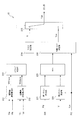
図1は、本発明の第1実施形態における制御装置を備える電動車両100の主要構成を示すブロック図である。
(First embodiment)
FIG. 1 is a block diagram illustrating a main configuration of an electric vehicle 100 including a control device according to the first embodiment of the present invention.
電動車両100は、電電動機を駆動源とする電気自動車である。本実施形態の電動車両100は、ドライバがアクセルペダルの踏込み量を操作することで電動車両100の加減速や停止を制御する。電動車両100を加速する際にはドライバがアクセルペダルを踏み込み、減速時や停止時にはドライバがアクセルペダルの踏み込み量を減らす、又はアクセルペダルの踏み込み量をゼロに操作する。
The electric vehicle 100 is an electric vehicle using an electric motor as a drive source. In the electric vehicle 100 of the present embodiment, the driver controls the acceleration / deceleration and stop of the electric vehicle 100 by operating the depression amount of the accelerator pedal. When accelerating electric vehicle 100, the driver depresses the accelerator pedal, and when decelerating or stopping, the driver reduces the depressing amount of the accelerator pedal, or manipulates the depressing amount of the accelerator pedal to zero.
電動車両100は、モータ4と、減速機5と、ドライブシャフト6と、駆動輪7a及び7bと、従属輪7c及び7dと、摩擦ブレーキ8a乃至8dと、パーキングブレーキ9c及び9dと、電流センサ11と、回転センサ12と、車輪速センサ13a乃至13dと、液圧センサ14と、制御装置110とを含む。
The electric vehicle 100 includes a motor 4, a speed reducer 5, a drive shaft 6, drive wheels 7a and 7b, dependent wheels 7c and 7d, friction brakes 8a to 8d, parking brakes 9c and 9d, and a current sensor 11. A rotation sensor 12, wheel speed sensors 13 a to 13 d, a hydraulic pressure sensor 14, and a control device 110.
制御装置110は、電動車両100の動作を制御する。制御装置110は、プログラムされた中央演算装置(CPU)に記憶装置が接続されており、中央演算装置は、制御プログラムや車速制御処理等の各種処理手順を規定したプログラム、及び所要データを格納するための読み出し専用メモリ(ROM)やランダムアクセスメモリ(RAM)などの内部メモリを有し、これらプログラム等により電動車両100における各種手段を実現している。制御装置110は、バッテリ1と、モータコントローラ2と、インバータ3と、ブレーキコントローラ10と、前後Gセンサ15と、を備える。
Control device 110 controls the operation of electric vehicle 100. The control device 110 has a storage device connected to a programmed central processing unit (CPU), and the central processing unit stores a program defining various processing procedures such as a control program and a vehicle speed control process, and necessary data. Internal memory such as a read-only memory (ROM) and a random access memory (RAM), and various means in the electric vehicle 100 are realized by these programs. The control device 110 includes a battery 1, a motor controller 2, an inverter 3, a brake controller 10, and a front / rear G sensor 15.
バッテリ1は、電動機であるモータ4に電力を供給する電源である。バッテリ1は、例えば、鉛電池やリチウムイオン電池などにより構成される。
The battery 1 is a power source that supplies electric power to a motor 4 that is an electric motor. The battery 1 is composed of, for example, a lead battery or a lithium ion battery.
モータコントローラ2は、電動車両100の作動状態を制御する制御装置を構成する。モータコントローラ2は、中央演算装置(CPU)、及び入出力インタフェース(I/Oインタフェース)を備えたマイクロコンピュータで構成される。モータコントローラ2は、電動車両100の作動状態に応じて、例えばモータ4を用いて電動車両100の制動トルクを付与する。
The motor controller 2 constitutes a control device that controls the operating state of the electric vehicle 100. The motor controller 2 includes a microcomputer having a central processing unit (CPU) and an input / output interface (I / O interface). The motor controller 2 applies the braking torque of the electric vehicle 100 using, for example, the motor 4 according to the operating state of the electric vehicle 100.
モータコントローラ2には、車速Vや、アクセル開度AP、モータ4の回転子位相α、モータ4に供給される電流iu、iv、iw等の車両状態を示す信号が入力される。モータコントローラ2は、入力信号を用いてモータ4の動作を制御するためのPWM(Pulse Width Modulation)信号を生成し、生成したPWM信号に応じてインバータ3の駆動信号を生成する。また、モータコントローラ2は、後述する方法により、摩擦制動量指令値を生成する。
The motor controller 2 receives signals indicating the vehicle state such as the vehicle speed V, the accelerator opening AP, the rotor phase α of the motor 4, and the currents iu, iv, iw supplied to the motor 4. The motor controller 2 generates a PWM (Pulse Width Modulation) signal for controlling the operation of the motor 4 using the input signal, and generates a drive signal for the inverter 3 in accordance with the generated PWM signal. The motor controller 2 generates a friction braking amount command value by a method described later.
インバータ3は、モータ4の各相に対応する2個のスイッチング素子(例えば、IGBTやMOS-FET等のパワー半導体素子)を有する。インバータ3は、スイッチング素子ごとに、モータコントローラ2で生成されたPWM信号に応じてスイッチング素子をオン/オフする。これにより、バッテリ1からモータ4へ供給される直流電流が交流電流に変換されるので、モータ4に対して所望の電流が供給されることになる。
The inverter 3 has two switching elements (for example, power semiconductor elements such as IGBT and MOS-FET) corresponding to each phase of the motor 4. The inverter 3 turns on / off the switching element for each switching element in accordance with the PWM signal generated by the motor controller 2. As a result, the direct current supplied from the battery 1 to the motor 4 is converted into an alternating current, so that a desired current is supplied to the motor 4.
モータ4は、電動車両100に駆動力と制動力を与える電動機であり、例えば三相交流モータにより実現される。モータ4は、インバータ3から供給される交流電流を受けて駆動力を発生し、減速機5及びドライブシャフト6を介して左右の駆動輪9a及び9bに駆動力を伝達する。
The motor 4 is an electric motor that applies driving force and braking force to the electric vehicle 100, and is realized by, for example, a three-phase AC motor. The motor 4 receives the alternating current supplied from the inverter 3, generates a driving force, and transmits the driving force to the left and right driving wheels 9 a and 9 b via the speed reducer 5 and the drive shaft 6.
モータ4は、電動車両100の走行中に駆動輪9a及び9bに連れ回されて回生駆動力を発生する。インバータ3は、モータ4の回生駆動力によって生じる交流電流を直流電流に変換してバッテリ1に供給する。このように、モータ4を用いて電動車両100の運動エネルギーを電気エネルギーに変換してバッテリ1に充電することにより、その運動エネルギーをバッテリ1に回収することができる。
The motor 4 is driven by the drive wheels 9a and 9b while the electric vehicle 100 is traveling to generate a regenerative driving force. The inverter 3 converts an alternating current generated by the regenerative driving force of the motor 4 into a direct current and supplies the direct current to the battery 1. Thus, the kinetic energy of the electric vehicle 100 is converted into electric energy using the motor 4 and the battery 1 is charged, so that the kinetic energy can be recovered in the battery 1.
駆動輪7a及び7bは、電動車両100の駆動時に路面に駆動力を伝達する車輪である。従属輪7c及び7dは、電動車両100の駆動輪7a及び7bに従属する車輪である。以下では、駆動輪7a及び7b並びに従属輪7c及び7dのことを各車輪と称する。
The driving wheels 7 a and 7 b are wheels that transmit driving force to the road surface when the electric vehicle 100 is driven. The dependent wheels 7 c and 7 d are wheels that are dependent on the driving wheels 7 a and 7 b of the electric vehicle 100. Hereinafter, the drive wheels 7a and 7b and the dependent wheels 7c and 7d are referred to as wheels.
摩擦ブレーキ8a乃至8dは、電動車両100に摩擦制動力を与える摩擦制動機構を構成する。本実施形態の摩擦ブレーキ8a乃至8dは、モータ4の回生可能制動力の上限値を超えた場合、あるいは、バッテリ1の充電状態や、駆動輪7a乃至7bのスリップ状態によりモータ4では制動トルクを賄えない場合に、摩擦制動力(摩擦トルク)を発生させる。
The friction brakes 8a to 8d constitute a friction braking mechanism that applies a friction braking force to the electric vehicle 100. The friction brakes 8a to 8d of the present embodiment provide braking torque to the motor 4 when the upper limit of the regenerative braking force of the motor 4 is exceeded, or due to the charged state of the battery 1 or the slip state of the drive wheels 7a to 7b. When it is not possible to cover, friction braking force (friction torque) is generated.
摩擦ブレーキ8a及び8bは、左右の駆動輪7a及び7bに設けられ、摩擦ブレーキ8c及び8dは、左右の従属輪7c及び7dに設けられる。摩擦ブレーキ8a乃至8dの各々は、電動車両100に摩擦制動力を与えるように、摩擦ブレーキ自身に供給される液体の圧力、いわゆるブレーキ液圧によって各車輪(7a乃至7d)のブレーキパッドをブレーキロータに押しつける。本実施形態では摩擦ブレーキ8a乃至8dに供給される液体としていわゆるブレーキ油が用いられる。
The friction brakes 8a and 8b are provided on the left and right drive wheels 7a and 7b, and the friction brakes 8c and 8d are provided on the left and right dependent wheels 7c and 7d. Each of the friction brakes 8a to 8d applies a brake pad of each wheel (7a to 7d) to a brake rotor by a liquid pressure supplied to the friction brake itself, so-called brake hydraulic pressure, so as to give a friction braking force to the electric vehicle 100. Press against. In this embodiment, so-called brake oil is used as the liquid supplied to the friction brakes 8a to 8d.
パーキングブレーキ9c及び9dは、電動車両100に摩擦制動力を与える摩擦制動機構を構成する。パーキングブレーキ9c及び9dは、従属輪7c及び7dに摩擦制動力を与えることにより、電動車両100が停止した状態、いわゆるパーキング状態を維持する。パーキングブレーキ9c及び9dは、例えば、ドラム式やワイヤー式の摩擦ブレーキにより実現される。例えば、ドライバが電動車両100のパーキングレバーを引く操作を行うと、パーキングブレーキ9c及び9dが作動してパーキング状態に遷移する。
The parking brakes 9c and 9d constitute a friction braking mechanism that applies a friction braking force to the electric vehicle 100. The parking brakes 9c and 9d maintain a state where the electric vehicle 100 is stopped, that is, a so-called parking state, by applying a friction braking force to the dependent wheels 7c and 7d. The parking brakes 9c and 9d are realized by, for example, drum type or wire type friction brakes. For example, when the driver performs an operation of pulling the parking lever of the electric vehicle 100, the parking brakes 9c and 9d are activated to shift to the parking state.
電流センサ11は、インバータ3からモータ4に供給される3相の交流電流である3相交流電流iu、iv、iwを検出する。なお、3相交流電流iu、iv、iwの和は0(ゼロ)であるため、任意の2相の電流を検出して残りの1相の電流を演算により求めてもよい。
The current sensor 11 detects three-phase alternating currents iu, iv, and iw that are three-phase alternating currents supplied from the inverter 3 to the motor 4. Since the sum of the three-phase alternating currents iu, iv, and iw is 0 (zero), any two-phase current may be detected and the remaining one-phase current may be obtained by calculation.
回転センサ12は、モータ4の回転子位相αを検出する。回転センサ12は、例えば、レゾルバやエンコーダにより構成される。
The rotation sensor 12 detects the rotor phase α of the motor 4. The rotation sensor 12 is constituted by, for example, a resolver or an encoder.
車輪速センサ13a乃至13dは、それぞれ駆動輪7a及び7b並びに従属輪7c及び7cの車輪の回転速度を検出する。
Wheel speed sensors 13a to 13d detect the rotational speeds of the wheels of the drive wheels 7a and 7b and the dependent wheels 7c and 7c, respectively.
液圧センサ14は、摩擦ブレーキ8a乃至8dに供給される油の圧力であるブレーキ液圧を検出する。
The hydraulic pressure sensor 14 detects a brake hydraulic pressure that is the pressure of oil supplied to the friction brakes 8a to 8d.
前後Gセンサ15は、電動車両100の進行方向に対して前後の加速度である前後Gを検出する。
The front / rear G sensor 15 detects front / rear G, which is a front / rear acceleration in the traveling direction of the electric vehicle 100.
ブレーキコントローラ10は、モータコントローラ2と共に電動車両100の制御装置を構成する。ブレーキコントローラ10は、アクセルペダル及びブレーキペダルの操作量に基づいて要求制動力(要求制動トルク)を算出する。そしてブレーキコントローラ10は、車速Vや、回生可能制動力、スリップ状態、アンダステア、オーバステアなどの車両状態に応じて要求制動力を回生制動力と摩擦制動力とに分配する。
The brake controller 10 constitutes a control device for the electric vehicle 100 together with the motor controller 2. The brake controller 10 calculates a required braking force (required braking torque) based on the operation amounts of the accelerator pedal and the brake pedal. The brake controller 10 distributes the required braking force to the regenerative braking force and the friction braking force according to the vehicle speed V, the regenerative braking force, the slip state, the understeer, the oversteer, and other vehicle conditions.
また、ブレーキコントローラ10は、モータコントローラ2で算出された摩擦制動量指令値に応じて摩擦ブレーキ8a乃至8dのブレーキ液圧を制御する。ブレーキコントローラ10は、液圧センサ14により検出されるブレーキ液圧が摩擦制動量指令値に応じて定まる値に追従するようフィードバック制御を行う。
The brake controller 10 controls the brake fluid pressure of the friction brakes 8a to 8d according to the friction braking amount command value calculated by the motor controller 2. The brake controller 10 performs feedback control so that the brake fluid pressure detected by the fluid pressure sensor 14 follows a value determined according to the friction braking amount command value.
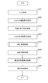
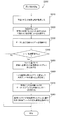
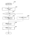
図2は、モータコントローラ2で実行されるモータ制御処理の処理手順例を示すフローチャートである。
FIG. 2 is a flowchart showing an example of a processing procedure of motor control processing executed by the motor controller 2.
ステップS201では、電動車両100の状態を示す車両状態信号がモータコントローラ2に入力される。ここでは、車両状態信号として、車速V(m/s)、アクセル開度AP(%)、モータ4の回転子位相α(rad)、モータ回転速度ωm(rpm/s)、三相交流電流iu、iv、iw、バッテリ1の直流電圧値Vdc(V)、摩擦制動量推定値B、及びブレーキペダルSWが入力される。
In step S201, a vehicle state signal indicating the state of the electric vehicle 100 is input to the motor controller 2. Here, as the vehicle state signal, the vehicle speed V (m / s), the accelerator opening AP (%), the rotor phase α (rad) of the motor 4, the motor rotational speed ωm (rpm / s), and the three-phase alternating current iu , Iv, iw, the DC voltage value Vdc (V) of the battery 1, the estimated friction braking amount B, and the brake pedal SW are input.
車速V(m/s)は、駆動輪7a及び7b並びに従属輪7c及び7dの車輪速である。車速Vは、図示しない車速センサや、他のコントローラから通信にて取得される。または、車速V(km/h)は、モータ回転速度(回転子機械角速度)ωmにタイヤ動半径rを乗じた値をファイナルギアのギア比により除して算出される。
Vehicle speed V (m / s) is the wheel speed of drive wheels 7a and 7b and dependent wheels 7c and 7d. The vehicle speed V is acquired by communication from a vehicle speed sensor (not shown) or another controller. Alternatively, the vehicle speed V (km / h) is calculated by dividing the value obtained by multiplying the motor rotational speed (rotor mechanical angular speed) ωm by the tire moving radius r by the gear ratio of the final gear.
アクセル開度AP(%)は、アクセルペダルの操作量を示すパラメータであり、図示しないアクセル開度センサから取得される。あるいは、アクセル開度APは、図示しない車両コントローラ等の他のコントローラから通信にて取得される。
Accelerator opening AP (%) is a parameter indicating the amount of operation of the accelerator pedal, and is acquired from an accelerator opening sensor (not shown). Or accelerator opening AP is acquired by communication from other controllers, such as a vehicle controller which is not illustrated.
モータ4の回転子位相α(rad)は、回転センサ12から取得される。モータ4の回転速度Nm(rpm)は、回転子角速度ω(電気角)をモータ4の極対数pで除算してモータ4の機械的な角速度であるモータ回転速度ωm(rad/s)を求め、求めたモータ回転速度ωmに60/(2π)を乗じて算出される。なお、回転子角速度ωは、回転子位相αを微分して算出される。
The rotor phase α (rad) of the motor 4 is acquired from the rotation sensor 12. The rotational speed Nm (rpm) of the motor 4 is obtained by dividing the rotor angular speed ω (electrical angle) by the pole pair number p of the motor 4 to obtain the motor rotational speed ωm (rad / s) which is the mechanical angular speed of the motor 4. The calculated motor rotational speed ωm is multiplied by 60 / (2π). The rotor angular velocity ω is calculated by differentiating the rotor phase α.
3相交流電流iu、iv及びiw(A)は、電流センサ11から取得される。
The three-phase alternating currents iu, iv and iw (A) are acquired from the current sensor 11.
直流電圧値Vdc(V)は、バッテリ1とインバータ3とを接続する直流電源ラインに配置した電圧センサ(不図示)から取得される。直流電圧値Vdc(V)は、バッテリコントローラ(不図示)から送信される電源電圧値を用いて求めてもよい。
The DC voltage value Vdc (V) is acquired from a voltage sensor (not shown) arranged on a DC power supply line connecting the battery 1 and the inverter 3. The DC voltage value Vdc (V) may be obtained using a power supply voltage value transmitted from a battery controller (not shown).
摩擦制動量推定値Bは、液圧センサ14から取得されるブレーキ液圧を用いて求められる。あるいは、摩擦制動量推定値Bは、ドライバによるブレーキペダルの踏込み量を検出するストロークセンサ(不図示)等の検出値を使用してもよい。なお、モータコントローラ2や他のコントローラで生成された摩擦制動量指令値を通信等にて取得し、取得した摩擦制動量指令値を摩擦制動量推定値Bとして用いてもよい。
The estimated friction braking amount B is obtained using the brake fluid pressure acquired from the fluid pressure sensor 14. Alternatively, the estimated value B of the friction braking amount may be a detection value of a stroke sensor (not shown) that detects the amount of depression of the brake pedal by the driver. The friction braking amount command value generated by the motor controller 2 or another controller may be acquired by communication or the like, and the acquired friction braking amount command value may be used as the friction braking amount estimated value B.
ブレーキペダルSWは、ドライバがブレーキペダルの踏み込み操作、すなわちブレーキ操作を行ったか否かを判別するためのスイッチ信号である。ブレーキペダルSWは、ブレーキペダルに付設されたブレーキスイッチ(不図示)から取得される。ブレーキペダルSW=1の場合は、ドライバによりブレーキペダルが操作されていることを示し、ブレーキペダルSW=0の場合は、ブレーキペダルが操作されていないことを示す。
The brake pedal SW is a switch signal for determining whether or not the driver has depressed the brake pedal, that is, whether or not the brake operation has been performed. The brake pedal SW is acquired from a brake switch (not shown) attached to the brake pedal. The brake pedal SW = 1 indicates that the brake pedal is operated by the driver, and the brake pedal SW = 0 indicates that the brake pedal is not operated.
ステップS202では、モータコントローラ2がトルク目標値算出処理を行う。
In step S202, the motor controller 2 performs a torque target value calculation process.
具体的には、モータコントローラ2は、ステップS201で入力されたアクセル開度AP及びモータ回転速度ωmに基づき、予め定められた演算テーブルを参照してトルク目標値Tm_tを設定する。図3には、演算テーブルの一例としてアクセル開度-トルクテーブルが示されている。
Specifically, the motor controller 2 sets the torque target value Tm_t with reference to a predetermined calculation table based on the accelerator opening AP and the motor rotation speed ωm input in step S201. FIG. 3 shows an accelerator opening-torque table as an example of the calculation table.
ステップS203では、モータコントローラ2が、モータ回転速度ωm及びトルク目標値Tm_tに基づいて勾配トルク推定処理を行う。
In step S203, the motor controller 2 performs gradient torque estimation processing based on the motor rotation speed ωm and the torque target value Tm_t.
具体的には、モータコントローラ2は、モータ回転速度ωm及びトルク目標値Tm_tに基づく外乱オブザーバを用いて、電動車両100に作用する勾配抵抗を打ち消す方向にモータ4を駆動するための勾配トルク推定値Td*を算出する。外乱オブザーバは、電動車両100の動作を運動方程式でモデル化した車両モデルを用いて構成される。
Specifically, the motor controller 2 uses the disturbance observer based on the motor rotational speed ωm and the torque target value Tm_t to estimate the gradient torque value for driving the motor 4 in the direction to cancel the gradient resistance acting on the electric vehicle 100. Td * is calculated. The disturbance observer is configured using a vehicle model in which the operation of the electric vehicle 100 is modeled by a motion equation.
さらに、モータコントローラ2は、摩擦ブレーキ8a乃至8dが電動車両100に与える摩擦制動力をモータ4のトルクに換算した摩擦トルクを求め、その摩擦トルクを勾配トルク推定値Td*から減じた値を新たな勾配トルク推定値Td*として算出する。
Further, the motor controller 2 obtains a friction torque obtained by converting the friction braking force applied to the electric vehicle 100 by the friction brakes 8a to 8d into the torque of the motor 4, and newly calculates a value obtained by subtracting the friction torque from the estimated gradient torque Td *. Is calculated as an estimated gradient torque value Td *.
勾配トルク推定値Td*は、電動車両100のモデル化誤差や、電動車両100に作用する空気抵抗及び勾配抵抗、タイヤの転がり抵抗などの外乱が要因となり変化する。勾配トルク推定値Tdの支配的な成分は勾配抵抗であることから、登坂路では勾配トルク推定値Tdが正(プラス)の値を採り、降坂路では勾配トルク推定値Tdが負(マイナス)の値を採り、平坦路では概ね0(ゼロ)となる。
The estimated gradient torque value Td * varies due to disturbances such as modeling errors of the electric vehicle 100, air resistance and gradient resistance acting on the electric vehicle 100, and rolling resistance of tires. Since the dominant component of the gradient torque estimated value Td is gradient resistance, the gradient torque estimated value Td takes a positive (plus) value on the uphill road, and the gradient torque estimated value Td takes a negative (minus) value on the downhill road. The value is taken and becomes approximately 0 (zero) on a flat road.
なお、モデル化誤差に関しては、例えば、電動車両100の乗員数や積載物が増加するほど、車両モデルに設定される電動車両100の重量の設定値と実際値とのズレ幅が大きくなり、モデル化誤差が大きくなる。また、勾配トルク推定処理の詳細については後述する。
Regarding the modeling error, for example, as the number of occupants and loads of the electric vehicle 100 increases, the difference between the set value of the weight of the electric vehicle 100 set in the vehicle model and the actual value increases. Increased error. Details of the gradient torque estimation process will be described later.
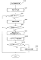
ステップS204では、モータコントローラ2がモータトルク指令値算出処理を行う。
In step S204, the motor controller 2 performs a motor torque command value calculation process.
具体的には、モータコントローラ2は、ステップS203で算出された勾配トルク推定値Td*をステップS202で算出されたトルク目標値Tm_tに加算し、加算した値をモータ4のトルク指令値を示すモータトルク指令値Tm*に設定する。
Specifically, the motor controller 2 adds the gradient torque estimated value Td * calculated in step S203 to the torque target value Tm_t calculated in step S202, and the added value indicates the torque command value of the motor 4. Set to torque command value Tm *.
このように、トルク目標値Tm_tに対して勾配トルク推定値Td*を加算することにより、電動車両100に作用する勾配抵抗が打ち消されるので、ドライバの要求に適したモータトルクTmを発生させることができる。
Thus, by adding the gradient torque estimated value Td * to the torque target value Tm_t, the gradient resistance acting on the electric vehicle 100 is canceled out, so that the motor torque Tm suitable for the driver's request can be generated. it can.
例えば、登坂路においては、電動車両100が進行方向に対して重力により戻される力を打ち消すようなモータトルクがモータトルク指令値Tm*に加味されるので、ドライバによるアクセルペダルの踏み増し操作を軽減することができる。
For example, on an uphill road, the motor torque that cancels the force returned by the gravity of the electric vehicle 100 with respect to the traveling direction is added to the motor torque command value Tm *, thereby reducing the driver's accelerator pedal depressing operation. can do.
また、降坂路においては、電動車両100の進行方向に対し重力による過剰な力を打ち消すようなモータトルクがモータトルク指令値Tm*に加味されるので、ドライバによるアクセルペダルからブレーキペダルへの踏み替え操作の回数を低減することができる。
On downhill roads, a motor torque that cancels excessive force due to gravity in the traveling direction of the electric vehicle 100 is added to the motor torque command value Tm *, so that the driver changes the accelerator pedal to the brake pedal. The number of operations can be reduced.
ステップS205では、モータコントローラ2が電動車両100を滑らかに停止させる停止制御処理を行う。
In step S205, the motor controller 2 performs a stop control process for smoothly stopping the electric vehicle 100.
本実施形態におけるモータコントローラ2は、電動車両100が停止するときに、電動車両100に与える制動力を、モータ4の回生制動力から摩擦ブレーキ8a乃至8dの摩擦制動力に切り替える。
The motor controller 2 in the present embodiment switches the braking force applied to the electric vehicle 100 from the regenerative braking force of the motor 4 to the friction braking force of the friction brakes 8a to 8d when the electric vehicle 100 stops.
具体的には、モータコントローラ2は、電動車両100が停止するか否か、すなわち電動車両100が停車間際であるか否かを判定する。例えば、モータコントローラ2は、車速Vが停車閾値よりも低下した場合には、電動車両100が停車間際であると判定する。
Specifically, the motor controller 2 determines whether or not the electric vehicle 100 stops, that is, whether or not the electric vehicle 100 is about to stop. For example, when the vehicle speed V falls below the stop threshold, the motor controller 2 determines that the electric vehicle 100 is about to stop.
上述の停車閾値は、停車の直前に停止制御処理が行われるよう電動車両100の速度を正確に検出できる範囲内の下限値に設定される。例えば、車速センサの分解能が時速5km(kph)である場合は、停車閾値は時速5kmに設定される。摩擦制動力よりも回生制動力の方が精度良く制御を行えることから、停車閾値を小さくすることにより回生制動力を用いて電動車両100を制動させる時間を長く確保することができる。よって、制動力を制御する精度の低下を抑制することができる。
The stop threshold described above is set to a lower limit within a range in which the speed of the electric vehicle 100 can be accurately detected so that the stop control process is performed immediately before the stop. For example, when the resolution of the vehicle speed sensor is 5 km / h (kph), the stop threshold is set to 5 km / h. Since the regenerative braking force can be controlled more accurately than the friction braking force, it is possible to secure a longer time for braking the electric vehicle 100 using the regenerative braking force by reducing the stop threshold value. Therefore, it is possible to suppress a decrease in accuracy for controlling the braking force.
モータコントローラ2は、電動車両100が停車間際であると判定した場合には、勾配トルク推定値Td*に応じて定められた制動力まで摩擦ブレーキ8a乃至8dの摩擦制動力が到達するように摩擦ブレーキ8a乃至8dの動作を制御する。
When the motor controller 2 determines that the electric vehicle 100 is about to stop, the motor controller 2 performs friction so that the friction braking force of the friction brakes 8a to 8d reaches the braking force determined according to the gradient torque estimated value Td *. The operation of the brakes 8a to 8d is controlled.
本実施形態のモータコントローラ2は、勾配トルク推定値Td*の大きさに応じて目標停止トルクを算出し、算出した目標停止トルクを摩擦制動量指令値としてブレーキコントローラ10に出力する。ここにいう目標停止トルクは、路面勾配による電動車両100のずり下がり(流動)を抑えて確実に停車できる制動トルクの値に設定される。
The motor controller 2 of the present embodiment calculates a target stop torque according to the magnitude of the gradient torque estimated value Td *, and outputs the calculated target stop torque to the brake controller 10 as a friction braking amount command value. The target stop torque referred to here is set to a value of braking torque that can stop the electric vehicle 100 due to a road surface gradient and suppress the sliding (flow) of the electric vehicle 100 with certainty.
例えば、目標停止トルクは、勾配トルク推定値Td*に対してあらかじめ定められた増加制動トルクを加算する。増加制動トルクは、例えば、勾配トルク推定値Tdの演算誤差や、摩擦ブレーキ8a乃至8dに供給される油の温度変化などを考慮して決定される。
For example, for the target stop torque, a predetermined increase braking torque is added to the gradient torque estimated value Td *. The increased braking torque is determined in consideration of, for example, calculation error of the gradient torque estimated value Td, temperature change of oil supplied to the friction brakes 8a to 8d, and the like.
具体的には、摩擦ブレーキ8a乃至8dにより発生する摩擦制動力は摩擦ブレーキ8a乃至8dの油温によって変化するので、増加制動トルクは、摩擦ブレーキ8a乃至8dにおける油温の変化に伴う摩擦制動力の低下量を考慮して決定される。なお、摩擦ブレーキ8a乃至8dの周囲に温度センサを設け、その温度センサの検出値に応じて増加制動トルクの大きさを変更するようにしてもよい。
Specifically, since the friction braking force generated by the friction brakes 8a to 8d varies depending on the oil temperature of the friction brakes 8a to 8d, the increased braking torque is the friction braking force accompanying the change of the oil temperature in the friction brakes 8a to 8d. It is determined in consideration of the amount of decrease. A temperature sensor may be provided around the friction brakes 8a to 8d, and the magnitude of the increased braking torque may be changed according to the detected value of the temperature sensor.
一方、増加制動トルクを大きくするほど、電動車両100の発進時に摩擦ブレーキ8a乃至8dの油圧を下げるのに要する時間が長くなってしまう。この対策として、増加制動トルクは、電動車両100の速やかな発進を実現できる摩擦トルクの上限値を超えないように設定される。
On the other hand, as the increased braking torque is increased, the time required for lowering the hydraulic pressure of the friction brakes 8a to 8d when the electric vehicle 100 starts is increased. As a countermeasure against this, the increased braking torque is set so as not to exceed the upper limit value of the friction torque that allows the electric vehicle 100 to start quickly.
このように、勾配トルク推定値Td*に応じて目標停止トルクを加算することにより、電動車両100の発進性の低下を抑制しつつ電動車両100を確実に停止させることが可能になる。
Thus, by adding the target stop torque according to the gradient torque estimated value Td *, it is possible to reliably stop the electric vehicle 100 while suppressing a decrease in startability of the electric vehicle 100.
また、ブレーキコントローラ10は、電動車両100が停止するときには、摩擦ブレーキ8a乃至8dから各車輪に対して速やかに摩擦制動力を与えられるよう、摩擦ブレーキ8a乃至8dに対して最初に供給すべき油圧に相当する摩擦初期トルクを設定する。摩擦初期トルクは、例えば、シミュレーション結果や実験データなどに基づいて予め定められるものであってもよい。
In addition, the brake controller 10 first supplies hydraulic pressure to the friction brakes 8a to 8d so that the friction braking force can be quickly applied to the wheels from the friction brakes 8a to 8d when the electric vehicle 100 stops. The friction initial torque corresponding to is set. The initial friction torque may be determined in advance based on, for example, simulation results or experimental data.
本実施形態のブレーキコントローラ10は、モータ4に生じる回生制動トルクの実値を摩擦初期トルクとして設定する。具体的には、モータコントローラ2が、3相交流電流iu、iv、iwからモータ4の回生トルクを推定してブレーキコントローラ10に出力し、ブレーキコントローラ10が、その回生トルクの推定値を摩擦初期トルクとして取得する。
The brake controller 10 of the present embodiment sets the actual value of the regenerative braking torque generated in the motor 4 as the initial friction torque. Specifically, the motor controller 2 estimates the regenerative torque of the motor 4 from the three-phase alternating currents iu, iv, iw and outputs it to the brake controller 10, and the brake controller 10 outputs the estimated value of the regenerated torque to the initial friction level. Get as torque.
ブレーキコントローラ10は、摩擦初期トルクを取得すると、各車輪に生じる摩擦トルクが摩擦初期トルクに達するように、摩擦ブレーキ8a乃至8dに供給される各油の圧力を上昇させる。
When the brake controller 10 acquires the initial friction torque, the brake controller 10 increases the pressure of each oil supplied to the friction brakes 8a to 8d so that the friction torque generated in each wheel reaches the initial friction torque.
次に、ブレーキコントローラ10は、摩擦ブレーキ8a乃至8dにより各車輪に与えられる摩擦トルクが摩擦初期トルクから目標停止トルクへと上昇するよう、摩擦ブレーキ8a乃至8dに供給される各油の圧力を増加させる。
Next, the brake controller 10 increases the pressure of each oil supplied to the friction brakes 8a to 8d so that the friction torque applied to each wheel by the friction brakes 8a to 8d increases from the initial friction torque to the target stop torque. Let
本実施形態のブレーキコントローラ10は、各車輪に生じる摩擦トルクが摩擦初期トルクから目標停止トルクに達するまでの間、電動車両100の前後Gが抑えられるよう、摩擦ブレーキ8a乃至8dに供給される油の昇圧速度を制御する。摩擦ブレーキ8a乃至8dの昇圧速度の制御手法については後述する。
The brake controller 10 according to the present embodiment provides oil supplied to the friction brakes 8a to 8d so that the front and rear G of the electric vehicle 100 is suppressed until the friction torque generated in each wheel reaches the target stop torque from the initial friction torque. The pressure increase speed is controlled. A method for controlling the boosting speed of the friction brakes 8a to 8d will be described later.
さらにブレーキコントローラ10は、摩擦ブレーキ8a乃至8dに供給される油を昇圧する場合には、モータ4の回生制動力が徐々に低下するようにモータトルク指令値Tm*を算出する。例えば、ブレーキコントローラ10は、予め定められたマップ又は演算式に従ってモータトルク指令値Tm*を算出する。ブレーキコントローラ10は、算出したモータトルク指令値Tm*をモータコントローラ2に回生制動量要求値RBrとして出力する。
Furthermore, the brake controller 10 calculates the motor torque command value Tm * so that the regenerative braking force of the motor 4 gradually decreases when the pressure of the oil supplied to the friction brakes 8a to 8d is increased. For example, the brake controller 10 calculates the motor torque command value Tm * according to a predetermined map or arithmetic expression. The brake controller 10 outputs the calculated motor torque command value Tm * to the motor controller 2 as a regenerative braking amount request value RBr.
ステップS206では、電動車両100が停車間際ではないと判定された場合にモータコントローラ2が制振制御処理を行う。
In step S206, when it is determined that the electric vehicle 100 is not about to stop, the motor controller 2 performs a vibration suppression control process.
具体的には、モータコントローラ2は、ステップS204で算出されるモータトルク指令値Tm*とモータ回転速度ωmとを用いて、モータトルク指令値Tm*に対し制振制御処理を施す。これにより、モータトルク指令値Tm*は、電動車両100における駆動軸トルクの応答を犠牲にすることなく、ドライブシャフト6の捩じり振動などのトルク伝達系振動を抑制するものとなる。制振制御処理の詳細については後述する。
Specifically, the motor controller 2 performs vibration suppression control processing on the motor torque command value Tm * using the motor torque command value Tm * and the motor rotation speed ωm calculated in step S204. Thus, the motor torque command value Tm * suppresses torque transmission system vibration such as torsional vibration of the drive shaft 6 without sacrificing the response of the drive shaft torque in the electric vehicle 100. Details of the vibration suppression control process will be described later.
ステップS207では、モータコントローラ2が電流指令値算出処理を行う。
In step S207, the motor controller 2 performs a current command value calculation process.
モータコントローラ2は、ステップS205で算出されるモータトルク指令値Tm*、又は、ステップS204でブレーキコントローラ10から出力されるモータトルク指令値Tm*に基づいて、d-q軸電流目標値を算出する。
The motor controller 2 calculates the dq-axis current target value based on the motor torque command value Tm * calculated in step S205 or the motor torque command value Tm * output from the brake controller 10 in step S204. .
具体的には、モータコントローラ2は、モータトルク指令値Tm*に加え、モータ回転速度ωmや直流電圧値Vdcなどを用いて、d軸電流目標値id*及びq軸電流目標値iq*を求める。
Specifically, the motor controller 2 calculates the d-axis current target value id * and the q-axis current target value iq * using the motor rotation speed ωm, the DC voltage value Vdc, and the like in addition to the motor torque command value Tm *. .
例えば、モータコントローラ2には、モータトルク指令値Tm*、モータ回転速度ωm、及び直流電圧値Vdcと、d軸電流目標値id*及びq軸電流目標値iq*と、の関係を定めた電流テーブルがあらいかじめ記録される。そしてモータコントローラ2は、モータトルク指令値Tm*、モータ回転速度ωm、及び直流電圧値Vdcを取得すると、電流テーブルを参照してd軸電流目標値id*及びq軸電流目標値iq*を求める。
For example, the motor controller 2 has a current that defines the relationship between the motor torque command value Tm *, the motor rotation speed ωm, the DC voltage value Vdc, and the d-axis current target value id * and the q-axis current target value iq *. The table is recorded in advance. When the motor controller 2 acquires the motor torque command value Tm *, the motor rotation speed ωm, and the DC voltage value Vdc, the motor controller 2 obtains the d-axis current target value id * and the q-axis current target value iq * by referring to the current table. .
ステップS208では、モータコントローラ2は、d軸電流id及びq軸電流iqがそれぞれステップS206で求めたd軸電流目標値id*及びq軸電流目標値iq*に対して一致(収束)するようインバータ3のスイッチング動作を制御する電流制御処理を行う。
In step S208, the motor controller 2 determines that the d-axis current id and the q-axis current iq match (converge) with the d-axis current target value id * and the q-axis current target value iq * obtained in step S206, respectively. Current control processing for controlling the switching operation 3 is performed.
具体的には、モータコントローラ2は、ステップS201で入力された三相交流電流iu、iv、iwとモータ4の回転子位相αとに基づいて、モータ4に供給されるd軸電流id及びq軸電流iqを推定する。続いてモータコントローラ2は、そのd軸電流idとd軸電流目標値id*との偏差からd軸電圧指令値vd*を算出するとともに、推定したq軸電流iqとq軸電流目標値iq*との偏差からq軸電圧指令値vq*を算出する。
Specifically, the motor controller 2 determines the d-axis currents id and q supplied to the motor 4 based on the three-phase alternating currents iu, iv, iw and the rotor phase α of the motor 4 input in step S201. The shaft current iq is estimated. Subsequently, the motor controller 2 calculates the d-axis voltage command value vd * from the deviation between the d-axis current id and the d-axis current target value id *, and the estimated q-axis current iq and q-axis current target value iq *. The q-axis voltage command value vq * is calculated from the deviation from.
そして、モータコントローラ2は、d軸電圧指令値vd*及びq軸電圧指令値vq*とモータ4の回転子位相αとから三相交流電圧指令値vu*、vv*、vw*を求める。続いてモータコントローラ2は、求めた三相交流電圧指令値vu*、vv*、vw*と直流電圧値Vdcとを用いて、PWM信号tu(%)、tv(%)、tw(%)を生成し、生成したPWM信号tu、tv、twをインバータ3に供給する。
The motor controller 2 obtains three-phase AC voltage command values vu *, vv *, and vw * from the d-axis voltage command value vd *, the q-axis voltage command value vq *, and the rotor phase α of the motor 4. Subsequently, the motor controller 2 uses the obtained three-phase AC voltage command values vu *, vv *, vw * and the DC voltage value Vdc to generate PWM signals tu (%), tv (%), tw (%). The generated PWM signals tu, tv, and tw are supplied to the inverter 3.
インバータ3に備えられたスイッチング素子はPWM信号tu、tv、twに応じて開閉するので、モータ4に生じるトルクがモータトルク指令値Tm*に収束するようにモータ4が回転駆動する。
Since the switching element provided in the inverter 3 opens and closes according to the PWM signals tu, tv, and tw, the motor 4 is rotationally driven so that the torque generated in the motor 4 converges to the motor torque command value Tm *.
次に、本実施形態におけるモータコントローラ2の構成について説明する。
Next, the configuration of the motor controller 2 in this embodiment will be described.
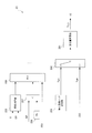
図3は、本実施形態におけるモータコントローラ2の機能構成の一例を示すブロック図である。
FIG. 3 is a block diagram showing an example of the functional configuration of the motor controller 2 in the present embodiment.
モータコントローラ2は、目標トルク演算部21と、勾配トルク演算部22と、指令トルク演算部23と、制振制御部24と、目標停止トルク演算部25と、停止制御切替器26と、を備える。
The motor controller 2 includes a target torque calculation unit 21, a gradient torque calculation unit 22, a command torque calculation unit 23, a vibration suppression control unit 24, a target stop torque calculation unit 25, and a stop control switch 26. .
目標トルク演算部21は、図2のステップS202で述べたトルク目標値算出処理を行う。上述のとおり、目標トルク演算部21は、アクセル開度AP及びモータ回転速度ωmを取得すると、図4に示したマップを参照して、取得したパラメータに関係付けられたトルク目標値Tm_tを算出する。
The target torque calculation unit 21 performs the torque target value calculation process described in step S202 of FIG. As described above, when the accelerator opening AP and the motor rotation speed ωm are acquired, the target torque calculation unit 21 calculates the torque target value Tm_t related to the acquired parameter with reference to the map shown in FIG. .
勾配トルク演算部22は、図2のステップS203で述べた勾配トルク推定処理を行う。上述のとおり、勾配トルク演算部22は、モータトルク指令値Tm*、摩擦制動量推定値B、モータ回転速度ωm及び車速Vを用いて、勾配トルク推定値Td*を演算する。なお、勾配トルク演算部22の構成例については図6を参照して後述する。
The gradient torque calculation unit 22 performs the gradient torque estimation process described in step S203 in FIG. As described above, the gradient torque calculation unit 22 calculates the gradient torque estimated value Td * using the motor torque command value Tm *, the friction braking amount estimated value B, the motor rotation speed ωm, and the vehicle speed V. A configuration example of the gradient torque calculator 22 will be described later with reference to FIG.
指令トルク演算部23は、勾配トルク推定値Td*とトルク目標値Tm_tと基づいてモータトルク指令値Tm*を演算する。本実施形態の指令トルク演算部23は、勾配トルク推定値Td*をトルク目標値Tm_tに加えてモータトルク指令値Tm*を算出する。
The command torque calculator 23 calculates a motor torque command value Tm * based on the gradient torque estimated value Td * and the torque target value Tm_t. The command torque calculation unit 23 of the present embodiment calculates the motor torque command value Tm * by adding the gradient torque estimated value Td * to the torque target value Tm_t.
なお、指令トルク演算部23は、登坂路や降坂路に応じて勾配トルク推定値Td*を補正し、補正した勾配トルク推定値Td*をトルク目標値Tm_tに加算するものであってもよい。これにより、傾斜のある路面での停車の際にドライバが受ける違和感を軽減することができる。
The command torque calculation unit 23 may correct the gradient torque estimated value Td * according to the uphill road or downhill road, and add the corrected gradient torque estimated value Td * to the torque target value Tm_t. Thereby, the uncomfortable feeling that the driver receives when the vehicle stops on an inclined road surface can be reduced.
制振制御部24は、図2のステップS206で述べたように、モータトルク指令値Tm*とモータ回転速度ωmとに基づいて制振制御処理を行う。制振制御部24の構成例については図7を参照して後述する。
The vibration damping control unit 24 performs a vibration damping control process based on the motor torque command value Tm * and the motor rotation speed ωm, as described in step S206 in FIG. A configuration example of the vibration suppression control unit 24 will be described later with reference to FIG.
目標停止トルク演算部25は、図2のステップS205で述べたように、勾配トルク推定値Td*に基づいて目標停止トルクTs_tを演算する。目標停止トルク演算部25の構成例については図8を参照して後述する。
The target stop torque calculating unit 25 calculates the target stop torque Ts_t based on the gradient torque estimated value Td * as described in step S205 of FIG. A configuration example of the target stop torque calculator 25 will be described later with reference to FIG.
停止制御切替器26は、図2のステップS205で述べたように、電動車両100が停止した場合に、回生トルクから摩擦トルクへの切替えの際に用いられる切替え回生トルクTm_swをモータトルク指令値Tm*に設定する。停止制御切替器26は、ブレーキコントローラ10から、切替え回生トルクTm_swを示すモータトルク指令値Tm*を回生制動量要求値RBrとして取得する。
As described in step S205 in FIG. 2, the stop control switching unit 26 sets the switching regenerative torque Tm_sw used when switching from the regenerative torque to the friction torque when the electric vehicle 100 stops, as a motor torque command value Tm. Set to *. The stop control switch 26 acquires a motor torque command value Tm * indicating the switching regenerative torque Tm_sw from the brake controller 10 as a regenerative braking amount request value RBr.
本実施形態の停止制御切替器26は、車速Vが所定の停車閾値未満になった場合には、モータトルク指令値Tm*を、制振制御部24の出力値から切替え回生トルクTm_swへ切り替える。
The stop control switching unit 26 of the present embodiment switches the motor torque command value Tm * from the output value of the vibration suppression control unit 24 to the switching regenerative torque Tm_sw when the vehicle speed V becomes less than a predetermined stop threshold.
<停止制御処理>
次に、ステップS203で行われる勾配トルク推定値Td*の導出手法について図面を参照して説明する。
<Stop control process>
Next, a method for deriving the gradient torque estimated value Td * performed in step S203 will be described with reference to the drawings.
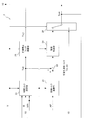
図5は、モータ4に生じるトルクであるモータトルクTmからモータ回転速度ωmまでの伝達特性Gp(s)を説明する図である。
FIG. 5 is a diagram for explaining the transfer characteristic Gp (s) from the motor torque Tm, which is the torque generated in the motor 4, to the motor rotational speed ωm.
図5には、電動車両100の駆動力伝達系をモデル化した車両モデルが示されている。車両モデルに用いられる各パラメータは、以下のとおりである。
FIG. 5 shows a vehicle model in which the driving force transmission system of the electric vehicle 100 is modeled. Each parameter used in the vehicle model is as follows.
Jm: モータ4のイナーシャ
Jw: 駆動輪のイナーシャ
M : 電動車両100の重量
Kd: 駆動系の捻り剛性
Kt: タイヤと路面の摩擦に関する係数
N : オーバーオールギヤ比
r : タイヤの荷重半径
ωm: モータ回転速度
Tm: モータトルク
Tw: 駆動輪のトルク
F : 電動車両100に加えられる力
V : 電動車両100の速度
ωw: 駆動輪の角速度
Tf: 摩擦制動量(モータ軸換算トルク)(≧0)
そして、図5に示した車両モデルにより、以下の運動方程式を導くことができる。
Jm: Inertia of motor 4 Jw: Inertia of drive wheel M: Weight of electric vehicle 100 Kd: Torsional rigidity of drive system Kt: Coefficient of friction between tire and road surface N: Overall gear ratio r: Tire load radius ωm: Motor rotation Speed Tm: Motor torque Tw: Driving wheel torque F: Force applied to the electric vehicle 100 V: Speed of the electric vehicle 100 ωw: Angular speed of the driving wheel Tf: Friction braking amount (motor shaft equivalent torque) (≧ 0)
The following equation of motion can be derived from the vehicle model shown in FIG.
ただし、式(1)~(3)中の符号の右上に付されているアスタリスク(*)は、時間微分を表している。
However, the asterisk (*) attached to the upper right of the sign in the equations (1) to (3) represents time differentiation.
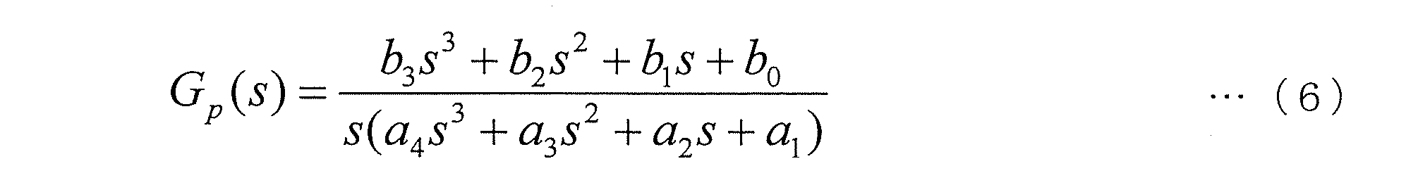
式(1)~(5)で示す運動方程式に基づいて、電動車両100に入力されるモータトルクTmからモータ回転速度ωmまでの伝達特性Gp(s)を求めると、次式(6)で表される。なお、上述の車両モデルから導出された伝達特性Gp(s)のことを以下では車両モデルGp(s)と称する。
The transfer characteristic Gp (s) from the motor torque Tm input to the electric vehicle 100 to the motor rotational speed ωm is obtained based on the equation of motion represented by the expressions (1) to (5). Is done. Note that the transfer characteristic Gp (s) derived from the vehicle model described above is hereinafter referred to as a vehicle model Gp (s).
ただし、式(6)中の各パラメータは、次式(7)で表される。
However, each parameter in equation (6) is represented by the following equation (7).
式(6)に示す伝達関数の極と零点を調べると、次式(8)の伝達関数に近似することができ、1つの極と1つの零点は極めて近い値を示す。これは、次式(8)のαとβが極めて近い値を示すことに相当する。
When the poles and zeros of the transfer function shown in Equation (6) are examined, it can be approximated to the transfer function of the following Equation (8), and one pole and one zero show extremely close values. This corresponds to that α and β in the following formula (8) show extremely close values.
従って、式(8)においてα=βと近似する極零相殺を行うことにより、次式(9)に示すように、Gp(s)は、(2次)/(3次)の伝達特性を構成する。
Therefore, by performing pole-zero cancellation that approximates α = β in equation (8), Gp (s) has a (second order) / (third order) transfer characteristic as shown in the following equation (9). Constitute.
また、ステップS205で行われる制振制御処理を併用する際は、車両モデルGp(s)は、制振制御処理のアルゴリズムにより、次式(10)で示すとおり、制振制御処理を適用した場合の車両応答を示す車両モデルGr(s)と見なすことができる。
When the vibration suppression control process performed in step S205 is used in combination, the vehicle model Gp (s) is applied with the vibration suppression control process as shown by the following expression (10) by the algorithm of the vibration suppression control process. It can be regarded as a vehicle model Gr (s) indicating the vehicle response.
なお、制振制御処理は、特開2001-45613号公報に記載されている制振制御処理でもよいし、特開2002-152916号公報に記載されている制振制御処理であってもよい。
Note that the vibration suppression control process may be the vibration suppression control process described in Japanese Patent Application Laid-Open No. 2001-45613 or the vibration suppression control process described in Japanese Patent Application Laid-Open No. 2002-152916.
続いて、ステップS205で行われる停止制御処理の詳細について図6乃至図9を参照しながら説明する。
Next, details of the stop control process performed in step S205 will be described with reference to FIGS.
図6は、勾配トルク推定値Td*を算出する勾配トルク演算部22の機能構成を示すブロック図である。
FIG. 6 is a block diagram showing a functional configuration of the gradient torque calculation unit 22 for calculating the gradient torque estimated value Td *.
勾配トルク演算部22は、摩擦トルク推定部221と、制御ブロック222と、制御ブロック223と、演算器224と、制御ブロック225とを備える。
The gradient torque calculation unit 22 includes a friction torque estimation unit 221, a control block 222, a control block 223, a calculator 224, and a control block 225.
摩擦トルク推定部221は、摩擦制動量推定値Bと車速Vとに基づいて、摩擦トルク推定値を算出する。摩擦トルク推定部221では、摩擦制動量推定値Bからモータ軸のトルク換算を行うための乗算処理や、液圧センサ14により検出された値から実制動力までの応答性等を考慮して摩擦制動量推定値Bが算出される。
The friction torque estimating unit 221 calculates a friction torque estimated value based on the friction braking amount estimated value B and the vehicle speed V. The friction torque estimator 221 takes into account the multiplication process for converting the torque of the motor shaft from the estimated friction braking value B, the responsiveness from the value detected by the hydraulic pressure sensor 14 to the actual braking force, and the like. A braking amount estimated value B is calculated.
制御ブロック222は、H(s)/Gr(s)なる伝達特性を有するフィルタとしての機能を有しており、モータ回転速度ωmに対してフィルタリング処理を施すことにより、第1のモータトルク推定値を算出する。この第1のモータトルク推定値は、モータ回転速度ωmから推定される現在のモータトルクである。
The control block 222 has a function as a filter having a transfer characteristic of H (s) / Gr (s), and performs a filtering process on the motor rotation speed ωm, thereby providing a first motor torque estimated value. Is calculated. This first motor torque estimated value is the current motor torque estimated from the motor rotation speed ωm.
上記の伝達特性H(s)は、分母次数と分子次数との差分が、制振制御処理を適用した場合のモータトルクTmからモータ回転速度ωmまでの式(10)に示した伝達特性である車両モデルGr(s)における分母次数と分子次数との差分以上となる伝達特性を有するローパスフィルタである。
The above transfer characteristic H (s) is the transfer characteristic shown in the equation (10) in which the difference between the denominator order and the numerator order is from the motor torque Tm to the motor rotational speed ωm when the vibration suppression control process is applied. It is a low-pass filter having a transfer characteristic that is equal to or greater than the difference between the denominator order and the numerator order in the vehicle model Gr (s).
制御ブロック223は、H(s)なる伝達特性を有するローパスフィルタとしての機能を有しており、モータトルク指令値Tm*に対してフィルタリング処理を行うことにより、第2のモータトルク推定値を算出する。この第2のモータトルク推定値は、モータトルク指令値Tm*から推定されるモータトルクである。
The control block 223 has a function as a low-pass filter having a transfer characteristic of H (s), and calculates a second estimated motor torque value by performing a filtering process on the motor torque command value Tm *. To do. The second motor torque estimated value is a motor torque estimated from the motor torque command value Tm *.
演算器224は、第2のモータトルク推定値から第1のモータトルク推定値を減じたトルク偏差を算出し、その偏差から摩擦トルク推定値を減じて得られた値を制御ブロック225に出力する。このように、演算器224は、路面勾配によって電動車両100に作用する力を打ち消すのに必要となるモータトルクを得るために、モータトルクの指令値に対する実際値の差分を算出するにあたり、その差分に含まれ得る摩擦トルク成分を取り除いている。
The arithmetic unit 224 calculates a torque deviation obtained by subtracting the first motor torque estimated value from the second motor torque estimated value, and outputs a value obtained by subtracting the friction torque estimated value from the deviation to the control block 225. . Thus, in order to obtain the motor torque required to cancel the force acting on the electric vehicle 100 due to the road surface gradient, the calculator 224 calculates the difference between the actual values with respect to the command value of the motor torque. The friction torque component which may be contained in is removed.
制御ブロック225は、Hz(s)なる伝達特性を有するフィルタであり、演算器224の出力に対してフィルタリング処理を行うことにより、勾配トルク推定値Td*を算出する。
The control block 225 is a filter having a transfer characteristic of Hz (s), and calculates a gradient torque estimated value Td * by performing a filtering process on the output of the computing unit 224.
ここで、伝達特性Hz(s)について説明する。上記式(10)を書き換えると、次式(11)が得られる。ただし、式(11)中のζz、ωz、ωpはそれぞれ、式(12)で表される。
Here, the transfer characteristic Hz (s) will be described. When the above equation (10) is rewritten, the following equation (11) is obtained. However, ζz, ωz, and ωp in equation (11) are each expressed by equation (12).
以上より、伝達特性Hz(s)を次式(13)で表すことができる。
From the above, the transfer characteristic Hz (s) can be expressed by the following equation (13).
上述のとおり算出される勾配トルク推定値Td*は、図11に示すとおり、外乱オブザーバにより推定されるものであって、車両に作用する外乱を表すパラメータである。
The gradient torque estimated value Td * calculated as described above is estimated by a disturbance observer as shown in FIG. 11, and is a parameter representing a disturbance acting on the vehicle.
ここで、車両に作用する外乱としては、空気抵抗、乗員数や積載量に起因する車両質量の変動によるモデル化誤差、タイヤの転がり抵抗、路面の勾配抵抗等が考えられるが、停車間際やイニシャルスタート時に支配的となる外乱要因は勾配抵抗である。本実施形態の勾配トルク演算部22は、上述のとおり、モータトルク指令値Tm*と、モータ回転速度ωmと、制振制御処理を適用した車両モデルGr(s)とに基づいて勾配トルク推定値Td*を算出するので、上述した外乱要因を一括して推定する。このため、いかなる運転条件においても、減速からの滑らかな停車を実現することができる。
Here, disturbances acting on the vehicle may include air resistance, modeling error due to changes in vehicle mass due to the number of passengers and loading capacity, tire rolling resistance, road surface slope resistance, etc. The disturbance factor that becomes dominant at the start is gradient resistance. As described above, the gradient torque calculation unit 22 of the present embodiment is based on the motor torque command value Tm *, the motor rotation speed ωm, and the vehicle model Gr (s) to which the vibration suppression control process is applied. Since Td * is calculated, the above-described disturbance factors are collectively estimated. For this reason, it is possible to realize a smooth stop from deceleration under any driving condition.
<制振制御処理>
次に、図2のステップS206で制振制御部24によって行われる制振制御処理について説明する。
<Vibration control processing>
Next, the vibration suppression control process performed by the vibration suppression control unit 24 in step S206 of FIG. 2 will be described.
図7は、本実施形態における制振制御部24の機能構成の一例を示すブロック図である。
FIG. 7 is a block diagram illustrating an example of a functional configuration of the vibration suppression control unit 24 in the present embodiment.
制振制御部24は、F/F補償器241と、加算器242と、F/B補償器243とを備える。
The vibration suppression control unit 24 includes an F / F compensator 241, an adder 242, and an F / B compensator 243.
F/F補償器241は、Gr(s)/Gp(s)なる伝達特性を有するフィルタとして機能する。Gr(s)/Gp(s)なる伝達特性は、上記の式(10)で示した車両モデルGr(s)と、式(6)で示した車両モデルGp(s)の逆系とから構成される。
The F / F compensator 241 functions as a filter having a transfer characteristic of Gr (s) / Gp (s). The transfer characteristic Gr (s) / Gp (s) is composed of the vehicle model Gr (s) expressed by the above equation (10) and the inverse system of the vehicle model Gp (s) expressed by the equation (6). Is done.
F/F補償器241は、モータトルク指令値Tm*に対してフィルタリング処理を行うことにより、フィードフォワード補償による制振制御処理を行う。F/F補償器241は、フィードフォワード補償による制振制御処理が施されたモータトルク指令値を加算器242に出力する。
The F / F compensator 241 performs a vibration suppression control process by feedforward compensation by performing a filtering process on the motor torque command value Tm *. The F / F compensator 241 outputs to the adder 242 a motor torque command value that has been subjected to vibration suppression control processing by feedforward compensation.
なお、F/F補償器241で行われる制振制御処理は、特開2001-45613号公報に記載されている制振制御処理でもよいし、特開2002-152916号公報に記載されている制振制御処理であってもよい。
Note that the vibration suppression control process performed by the F / F compensator 241 may be the vibration suppression control process described in Japanese Patent Laid-Open No. 2001-45613, or the vibration suppression control process described in Japanese Patent Laid-Open No. 2002-152916. The vibration control process may be performed.
加算器242は、F/F補償器241の出力値にF/B補償器243の出力値を加えてモータトルク指令値Tm*を新たに算出する。加算器242は、算出したモータトルク指令値Tm*を、停止制御切替器26及びF/B補償器243に出力する。
The adder 242 newly calculates the motor torque command value Tm * by adding the output value of the F / B compensator 243 to the output value of the F / F compensator 241. The adder 242 outputs the calculated motor torque command value Tm * to the stop control switch 26 and the F / B compensator 243.
F/B補償器243は、フィードバック制御に用いられるフィルタである。F/B補償器243は、制御ブロック2431と、減算器2432と、制御ブロック2433と、ゲイン補償器2434とを備える。
The F / B compensator 243 is a filter used for feedback control. The F / B compensator 243 includes a control block 2431, a subtractor 2432, a control block 2433, and a gain compensator 2434.
制御ブロック2431は、上述の車両モデルGp(s)なる伝達特性を有するフィルタとして機能する。制御ブロック2431は、加算器242の出力値であるモータトルク指令値Tm*に対してフィルタリング処理を行うことにより、モータ回転速度の推定値を出力する。
The control block 2431 functions as a filter having a transfer characteristic that is the above-described vehicle model Gp (s). The control block 2431 outputs an estimated value of the motor rotation speed by performing a filtering process on the motor torque command value Tm * that is an output value of the adder 242.
減算器2432は、モータ回転速度ωmを制御ブロック2431の推定値から減じた偏差を算出し、算出した偏差を制御ブロック2433に出力する。
The subtractor 2432 calculates a deviation obtained by subtracting the motor rotation speed ωm from the estimated value of the control block 2431, and outputs the calculated deviation to the control block 2433.
制御ブロック2433は、伝達特性H(s)を有するローパスフィルタと車両モデルGp(s)の逆系とから構成されるH(s)/Gp(s)なる伝達特性を有するフィルタとして機能する。制御ブロック2433は、減算器2432からの偏差に対してフィルタリング処理を行うことによりF/B補償トルクを算出し、そのF/B補償トルクをゲイン補償器2434に出力する。
The control block 2433 functions as a filter having a transfer characteristic of H (s) / Gp (s) configured by a low-pass filter having a transfer characteristic H (s) and an inverse system of the vehicle model Gp (s). The control block 2433 calculates F / B compensation torque by performing a filtering process on the deviation from the subtractor 2432, and outputs the F / B compensation torque to the gain compensator 2434.
ゲイン補償器2434は、F/B補償トルクにゲインKFBを乗算するフィルタである。なお、ゲインKFBを調整することにより、F/B補償器243の安定性を確保することができる。ゲイン補償器2434は、ゲイン調整されたF/B補償トルクを加算器242に出力する。
The gain compensator 2434 is a filter that multiplies the F / B compensation torque by the gain K FB . Note that the stability of the F / B compensator 243 can be ensured by adjusting the gain K FB . The gain compensator 2434 outputs the gain adjusted F / B compensation torque to the adder 242.
そして、加算器242において、F/B補償トルクと、F/F補償器241による制振制御処理が施されたモータトルク指令値Tm*と、とが加算されることにより、電動車両100の駆動力伝達系の振動を抑制するモータトルク指令値Tm*が算出される。
Then, the adder 242 adds the F / B compensation torque and the motor torque command value Tm * subjected to the vibration suppression control process by the F / F compensator 241, thereby driving the electric vehicle 100. A motor torque command value Tm * that suppresses vibration of the force transmission system is calculated.
なお、図7に示した制振制御処理は一例であり、特開2003-9566号公報に記載されている制振制御処理でもよいし、特開2010-288332号公報に記載されている制振制御処理であってもよい。
Note that the vibration suppression control process shown in FIG. 7 is an example, and may be the vibration suppression control process described in Japanese Patent Application Laid-Open No. 2003-9566, or the vibration suppression control process described in Japanese Patent Application Laid-Open No. 2010-288332. It may be a control process.
次に、図2のステップS205で目標停止トルク演算部25によって算出される目標停止トルクの算出手法について説明する。
Next, a method for calculating the target stop torque calculated by the target stop torque calculator 25 in step S205 of FIG. 2 will be described.
図8は、目標停止トルク演算部25の機能構成の一例を示すブロック図である。目標停止トルク演算部25は、停車補正ゲイン設定部251と、乗算器252と、マスク設定部253と、目標停止トルク出力部254と、を備える。
FIG. 8 is a block diagram illustrating an example of a functional configuration of the target stop torque calculation unit 25. As illustrated in FIG. The target stop torque calculation unit 25 includes a vehicle stop correction gain setting unit 251, a multiplier 252, a mask setting unit 253, and a target stop torque output unit 254.
停車補正ゲイン設定部251は、路面勾配に拘わらず電動車両100を停止させるのに必要となる停車補正ゲインを乗算器252に出力する。停車補正ゲインは、ステップS205で述べたように、摩擦ブレーキ8a乃至8dにおける摩擦制動力の温度依存性等を考慮して、電動車両100の発進性を確保しつつ電動車両100が確実に停止するような値に予め設定される。停車補正ゲインは1.0よりも大きな値に設定される。
The stop correction gain setting unit 251 outputs a stop correction gain necessary for stopping the electric vehicle 100 to the multiplier 252 regardless of the road surface gradient. As described in step S <b> 205, the stop correction gain takes into account the temperature dependence of the friction braking force in the friction brakes 8 a to 8 d and the like, while ensuring the startability of the electric vehicle 100, the electric vehicle 100 reliably stops. Such a value is preset. The stop correction gain is set to a value larger than 1.0.
乗算器252は、勾配トルク演算部22からの勾配トルク推定値Td*に停車補正ゲインを乗じた値を目標停止トルク出力部254に出力する。
The multiplier 252 outputs a value obtained by multiplying the gradient torque estimated value Td * from the gradient torque calculation unit 22 by the stop correction gain to the target stop torque output unit 254.
マスク設定部253は、目標停止トルクをマスクするために、目標停止トルク出力部254に0を出力する。
The mask setting unit 253 outputs 0 to the target stop torque output unit 254 in order to mask the target stop torque.
目標停止トルク出力部254は、電動車両100が停止するか否かを判断し、電動車両100が停止する場合には、摩擦トルクの目標値を示す目標停止トルクTs_tを、マスク設定部253の出力値から乗算器252の出力値に切替える。
The target stop torque output unit 254 determines whether or not the electric vehicle 100 stops. When the electric vehicle 100 stops, the target stop torque Ts_t indicating the target value of the friction torque is output from the mask setting unit 253. The value is switched to the output value of the multiplier 252.
本実施形態における目標停止トルク出力部254は、車速Vが停止閾値未満である場合には、勾配トルク推定値Td*に停車補正ゲインを乗算した値を目標停止トルクTs_tとしてブレーキコントローラ10に出力する。一方、目標停止トルク出力部254は、車速Vが停止閾値以上である場合には、目標停止トルクTs_tとして0をブレーキコントローラ10に出力する。
When the vehicle speed V is less than the stop threshold, the target stop torque output unit 254 in the present embodiment outputs a value obtained by multiplying the gradient torque estimated value Td * by the stop correction gain to the brake controller 10 as the target stop torque Ts_t. . On the other hand, when the vehicle speed V is equal to or higher than the stop threshold, the target stop torque output unit 254 outputs 0 as the target stop torque Ts_t to the brake controller 10.
このように、目標停止トルク演算部25は、電動車両100の停止を予測したときには、電動車両100が路面勾配にかかわらず摩擦制動力で確実に停止するような目標停止トルクTs_tをブレーキコントローラ10に指示する。
As described above, when the target stop torque calculating unit 25 predicts the stop of the electric vehicle 100, the target stop torque Ts_t that causes the electric vehicle 100 to stop reliably with the friction braking force regardless of the road surface gradient is given to the brake controller 10. Instruct.
図9は、本実施形態におけるブレーキコントローラ10の機能構成の一例を示すブロック図である。
FIG. 9 is a block diagram illustrating an example of a functional configuration of the brake controller 10 according to the present embodiment.
ブレーキコントローラ10は、切替判定部101と、ミニマムセレクト102と、トルク切替器103と、タイマ104と、昇圧速度演算部105と、昇圧速度上限設定部106と、昇圧速度切替器107と、摩擦トルク演算部108と、前回値設定部109とを備える。
The brake controller 10 includes a switching determination unit 101, a minimum select 102, a torque switch 103, a timer 104, a boost speed calculation unit 105, a boost speed upper limit setting unit 106, a boost speed switch 107, and a friction torque. A calculation unit 108 and a previous value setting unit 109 are provided.
切替判定部101は、摩擦トルクの前回値Tf-1*がモータトルクTmに達したか否かを判断する。切替判定部101には、摩擦ブレーキ8a乃至8dの摩擦初期トルクTf_iとしてモータトルクTmが入力される。モータトルクTmは、例えば一般的な手法により三相交流電流iu、iv、iwから算出される。
The switching determination unit 101 determines whether or not the previous value Tf −1 * of the friction torque has reached the motor torque Tm. The switch determination unit 101 receives the motor torque Tm as the initial friction torque Tf_i of the friction brakes 8a to 8d. The motor torque Tm is calculated from the three-phase alternating currents iu, iv, iw by a general method, for example.
切替判定部101は、摩擦トルクの前回値Tf-1*がモータトルクTmに達していないと判断した場合には、摩擦ブレーキ8a乃至8dの初期設定信号を、トルク切替器103及び昇圧速度切替器107にそれぞれ出力する。
When the switching determination unit 101 determines that the previous value Tf −1 * of the friction torque has not reached the motor torque Tm, the switching determination unit 101 receives an initial setting signal for the friction brakes 8a to 8d as a torque switch 103 and a boost speed switch. The data are output to 107 respectively.
一方、切替判定部101は、摩擦トルクの前回値Tf-1*がモータトルクTmに達したと判断した場合には、摩擦ブレーキ8a乃至8dの昇圧制御信号を、トルク切替器103及び昇圧速度切替器107にそれぞれ出力する。
On the other hand, when the switching determination unit 101 determines that the previous value Tf −1 * of the friction torque has reached the motor torque Tm, the switching determination unit 101 sends the boost control signal of the friction brakes 8a to 8d to the torque switch 103 and the boost speed switching. Output to each of the devices 107.
ミニマムセレクト102は、モータトルクTmと目標停止トルクTs_tとのうち小さい方の値を摩擦初期トルクTf_iとしてトルク切替器103に出力する。例えば、モータトルクTmが目標停止トルクTs_tよりも小さい場合には、ミニマムセレクト102は、摩擦初期トルクTf_iとしてモータトルクTmをトルク切替器103に出力する。
The minimum select 102 outputs the smaller value of the motor torque Tm and the target stop torque Ts_t to the torque switch 103 as the initial friction torque Tf_i. For example, when the motor torque Tm is smaller than the target stop torque Ts_t, the minimum select 102 outputs the motor torque Tm to the torque switch 103 as the initial friction torque Tf_i.
トルク切替器103は、切替判定部101から出力される信号に応じて、摩擦トルク演算部108に出力される制動トルクを、摩擦初期トルクTf_iから目標停止トルクTs_tへ切り替える。
The torque switch 103 switches the braking torque output to the friction torque calculator 108 from the initial friction torque Tf_i to the target stop torque Ts_t according to the signal output from the switching determination unit 101.
具体的には、トルク切替器103は、切替判定部101から初期設定信号を受信した場合には、摩擦初期トルクTf_iを摩擦トルク演算部108に出力する。一方、トルク切替器103は、切替判定部101から昇圧制御信号を受信した場合には、目標停止トルクTs_tを摩擦トルク演算部108に出力する。
Specifically, when the torque switch 103 receives the initial setting signal from the switching determination unit 101, the torque switch 103 outputs the friction initial torque Tf_i to the friction torque calculation unit 108. On the other hand, when receiving the boost control signal from the switching determination unit 101, the torque switch 103 outputs the target stop torque Ts_t to the friction torque calculation unit 108.
タイマ104は、目標停止トルクTs_tが0(ゼロ)であるか否かを判断し、目標停止トルクTs_tが0である場合には、タイマ104のカウント値を0に設定する。一方、目標停止トルクTs_tが0よりも大きくなった場合には、タイマ104は、カウントを開始し、カウント値を昇圧速度演算部105に出力する。すなわち、電動車両100が停止すると判定された場合には、タイマ104は、停車判定後の経過時間としてカウント値を昇圧速度演算部105に出力する。
The timer 104 determines whether or not the target stop torque Ts_t is 0 (zero). If the target stop torque Ts_t is 0, the timer 104 sets the count value of the timer 104 to 0. On the other hand, when the target stop torque Ts_t becomes larger than 0, the timer 104 starts counting and outputs the count value to the boosting speed calculation unit 105. That is, when it is determined that electric vehicle 100 is stopped, timer 104 outputs a count value to boosting speed calculation unit 105 as the elapsed time after the stoppage determination.
昇圧速度演算部105は、あらかじめ定められた演算テーブルや演算式などを用いて、昇圧速度を演算する。昇圧速度演算部105は、タイマ104のカウント値の大きさに応じて摩擦ブレーキ8a乃至8dの昇圧速度を算出する。昇圧速度演算部105は、算出した昇圧速度を摩擦トルク演算部108に出力する。
The boosting speed calculation unit 105 calculates the boosting speed using a predetermined calculation table or formula. The boosting speed calculation unit 105 calculates the boosting speed of the friction brakes 8a to 8d according to the count value of the timer 104. The boosting speed calculation unit 105 outputs the calculated boosting speed to the friction torque calculation unit 108.
本実施形態の昇圧速度演算部105には、摩擦ブレーキ8a乃至8dの昇圧速度とタイマ104のカウント値との関係を示す昇圧速度テーブルがあらかじめ記憶される。昇圧速度テーブルは、電動車両100を停止する場合においてドライバに対して違和感を与えないような昇圧速度に設定される。本実施形態ではタイマ104のカウント値が大きくなるほど、2次曲線を描くように摩擦ブレーキ8a乃至8dの昇圧速度が大きくなる。
In the boosting speed calculation unit 105 of the present embodiment, a boosting speed table indicating the relationship between the boosting speeds of the friction brakes 8a to 8d and the count value of the timer 104 is stored in advance. The boosting speed table is set to a boosting speed that does not give the driver a sense of incongruity when the electric vehicle 100 is stopped. In the present embodiment, the higher the count value of the timer 104, the higher the pressure increase speed of the friction brakes 8a to 8d so as to draw a quadratic curve.
昇圧速度上限設定部106は、摩擦ブレーキ8a乃至8dの昇圧速度に関する上限値をあらかじめ保持する。昇圧速度の上限値は、摩擦ブレーキ8a乃至8dの構造などを考慮して決定され、例えば、数万ニュートン(m/s)程度に設定される。昇圧速度上限設定部106は、昇圧速度の上限値を昇圧速度切替器107に設定する。
The boosting speed upper limit setting unit 106 holds in advance an upper limit value related to the boosting speed of the friction brakes 8a to 8d. The upper limit value of the pressure increase speed is determined in consideration of the structure of the friction brakes 8a to 8d, and is set to, for example, about several tens of thousands of newtons (m / s). The boosting speed upper limit setting unit 106 sets the upper limit value of the boosting speed in the boosting speed switch 107.
昇圧速度切替器107は、切替判定部101から出力される信号に応じて、摩擦トルク演算部108に出力される昇圧速度を切り替える。
The boosting speed switching unit 107 switches the boosting speed output to the friction torque calculating unit 108 in accordance with the signal output from the switching determining unit 101.
具体的には、昇圧速度切替器107は、切替判定部101から初期設定信号を受信した場合には、昇圧速度の上限値を摩擦トルク演算部108に出力する。一方、昇圧速度切替器107は、切替判定部101から昇圧制御信号を受信した場合には、昇圧速度演算部105で算出された昇圧速度を摩擦トルク演算部108に出力する。
Specifically, when receiving the initial setting signal from the switching determination unit 101, the boosting speed switching unit 107 outputs the upper limit value of the boosting speed to the friction torque calculating unit 108. On the other hand, when the boosting speed switching unit 107 receives the boosting control signal from the switching determining unit 101, the boosting speed switching unit 107 outputs the boosting speed calculated by the boosting speed calculating unit 105 to the friction torque calculating unit 108.
このように、昇圧速度切替器107は、摩擦トルクの前回値Tf-1*がモータトルクTmに達したときには、摩擦初期トルクTf_iから目標停止トルクTs_tへ増加させる際に滑らかに停車するような昇圧速度を摩擦トルク演算部108に設定する。
Thus, when the previous value Tf −1 * of the friction torque reaches the motor torque Tm, the step-up speed switching unit 107 increases the pressure so that the vehicle stops smoothly when the friction initial torque Tf_i is increased to the target stop torque Ts_t. The speed is set in the friction torque calculator 108.
摩擦トルク演算部108は、あらかじめ定められた演算テーブルや演算式などを用いて、電動車両200に与えるべき摩擦力を特定する摩擦トルク指令値Tf*を演算する。摩擦トルク演算部108は、昇圧速度切替器107から出力される昇圧速度の値と、トルク切替器103から出力される制動トルクの値とに基づいて、摩擦トルク指令値Tf*を算出する。
The friction torque calculation unit 108 calculates a friction torque command value Tf * that specifies the friction force to be applied to the electric vehicle 200 using a predetermined calculation table, calculation formula, or the like. The friction torque calculator 108 calculates the friction torque command value Tf * based on the value of the boosting speed output from the boosting speed switch 107 and the value of the braking torque output from the torque switch 103.
本実施形態の摩擦トルク演算部108には、摩擦トルク目標値と摩擦トルク指令値をそれぞれX軸とY軸にとり、摩擦トルク目標値と摩擦トルク指令値との関係を示す摩擦トルクテーブルがあらかじめ保持される。摩擦トルクテーブルについては、摩擦トルク目標と摩擦トルク指令値が比例関係にあり、摩擦トルク目標値(X)に対する摩擦トルク指令値(Y)の傾きaが昇圧速度切替器107からの昇圧速度の大きさに応じて変化する。例えば、昇圧速度が大きくなるほど、傾きaが大きくなる。
The friction torque calculation unit 108 of the present embodiment stores in advance a friction torque table that indicates the relationship between the friction torque target value and the friction torque command value by taking the friction torque target value and the friction torque command value on the X axis and the Y axis, respectively. Is done. In the friction torque table, the friction torque target and the friction torque command value are in a proportional relationship, and the gradient a of the friction torque command value (Y) with respect to the friction torque target value (X) is the magnitude of the boost speed from the boost speed switching device 107. It changes according to the height. For example, the slope a increases as the boosting speed increases.
摩擦トルク演算部108は、昇圧速度切替器107から昇圧速度を取得すると、その昇圧速度の大きさに応じて摩擦トルクテーブルの傾きaを変更する。そして摩擦トルク演算部108は、トルク切替器103から制動トルクを摩擦トルク目標値として取得すると、変更された摩擦トルクテーブルを参照し、取得した目標値に関係付けられた指令値を摩擦トルク指令値Tf*として算出する。
The friction torque calculation unit 108, when acquiring the boosting speed from the boosting speed switching unit 107, changes the slope a of the friction torque table according to the magnitude of the boosting speed. When the friction torque calculation unit 108 acquires the braking torque from the torque switch 103 as the friction torque target value, the friction torque calculation unit 108 refers to the changed friction torque table and determines the command value related to the acquired target value as the friction torque command value. Calculated as Tf *.
摩擦トルク演算部108は、算出した摩擦トルク指令値Tf*を、摩擦ブレーキ8a乃至8dの油圧を制御するための制御ブロックと前回値設定部109にそれぞれ出力する。
The friction torque calculation unit 108 outputs the calculated friction torque command value Tf * to the control block for controlling the hydraulic pressure of the friction brakes 8a to 8d and the previous value setting unit 109, respectively.
前回値設定部109は、摩擦トルク演算部108から摩擦トルク指令値Tf*を取得して次回の制御周期まで前回値として保持する。前回値設定部109は、次の制御周期において、保持した摩擦トルク指令値を前回値Tf-1*として切替判定部101に出力する。
The previous value setting unit 109 acquires the friction torque command value Tf * from the friction torque calculation unit 108 and holds it as the previous value until the next control cycle. The previous value setting unit 109 outputs the retained friction torque command value as the previous value Tf −1 * to the switching determination unit 101 in the next control cycle.
このように、ブレーキコントローラ10は、目標停止トルクTs_tが0よりも大きくなった場合に、モータ4に現に生じている回生トルクの値を摩擦初期トルクTf_iとして設定する。そしてブレーキコントローラ10は、摩擦トルクが摩擦初期トルクTf_iに達するよう摩擦ブレーキ8a乃至8dに供給されるブレーキ油を迅速に昇圧する。その後、ブレーキコントローラ10は、路面に勾配があっても確実に停車するように設定された目標停止トルクTs_tに摩擦トルクが達するまでの間、電動車両100のドライバに違和感を与えないようブレーキ油の昇圧速度を調整する。
Thus, when the target stop torque Ts_t becomes larger than 0, the brake controller 10 sets the value of the regenerative torque currently generated in the motor 4 as the initial friction torque Tf_i. Then, the brake controller 10 quickly boosts the brake oil supplied to the friction brakes 8a to 8d so that the friction torque reaches the friction initial torque Tf_i. After that, the brake controller 10 prevents the driver of the electric vehicle 100 from feeling uncomfortable until the friction torque reaches the target stop torque Ts_t that is set to stop reliably even when the road surface is inclined. Adjust the pressure increase speed.
すなわち、ブレーキコントローラ10は、電動車両100が停止する間際になると、電動車両100に摩擦制動力を精度良く与えられるようブレーキ油をあらかじめ昇圧する。その後、ブレーキコントローラ10は、電動車両100の状態に応じてブレーキ油の昇圧速度を調整しながら、電動車両100が確実に停止する摩擦制動力を与える。これにより、電動車両100に与えられる制動力が回生制動力から摩擦制動力に適切に切り替えられるので、電動車両100を停止させることができる。
That is, when the electric vehicle 100 is about to stop, the brake controller 10 boosts the brake oil in advance so that the friction braking force can be applied to the electric vehicle 100 with high accuracy. Thereafter, the brake controller 10 applies a friction braking force that reliably stops the electric vehicle 100 while adjusting the pressure increase speed of the brake oil according to the state of the electric vehicle 100. As a result, the braking force applied to the electric vehicle 100 is appropriately switched from the regenerative braking force to the friction braking force, so that the electric vehicle 100 can be stopped.
次に、本実施形態における電動車両100が停止する停止動作について図面を参照して説明する。
Next, a stop operation in which the electric vehicle 100 according to this embodiment stops will be described with reference to the drawings.
図10は、本実施形態における電動車両100が停止する場面の一例を示すタイムチャートである。
FIG. 10 is a time chart showing an example of a scene where the electric vehicle 100 stops in the present embodiment.
図10(a)乃至(e)には、それぞれ、車速Vと、勾配トルク推定値Td*と、停車判定後におけるタイマ104のカウント値と、摩擦ブレーキ8a乃至8dの昇圧速度と、電動車両100に与える制動トルクとが示されている。図10(a)乃至(e)の横軸は互いに共通の時間軸である。
FIGS. 10A to 10E show the vehicle speed V, the gradient torque estimated value Td *, the count value of the timer 104 after the stoppage determination, the boost speed of the friction brakes 8a to 8d, and the electric vehicle 100, respectively. The braking torque applied to is shown. The horizontal axes in FIGS. 10A to 10E are time axes common to each other.
この例では、登坂路を走行中の電動車両100が停止したときの電動車両100の状態が示されている。時刻t0以降、アクセル開度APが徐々に小さくなり、図10(a)に示すように、走行中の電動車両100の車速Vが低下する。このとき、図10(b)に示すように勾配トルク推定値Td*は、電動車両100が登坂路を走行しているため、正の値を採る。
In this example, the state of the electric vehicle 100 when the electric vehicle 100 traveling on the uphill road stops is shown. After time t0, the accelerator pedal opening AP gradually decreases, and the vehicle speed V of the electric vehicle 100 during traveling decreases as shown in FIG. At this time, as shown in FIG. 10B, the gradient torque estimated value Td * takes a positive value because the electric vehicle 100 is traveling on the uphill road.
時刻t1においては、図10(a)に示すように車速Vが停車閾値Th_sよりも低下し、目標停止トルク演算部25により電動車両100が停止すると判定される。このため、図10(e)に示すように、目標停止トルク演算部25により勾配トルク推定値Td*に基づき、勾配トルク推定値Td*よりも大きな値が目標停止トルクTs_tに設定される。
At time t1, as shown in FIG. 10A, the vehicle speed V falls below the stop threshold Th_s, and the target stop torque calculator 25 determines that the electric vehicle 100 stops. Therefore, as shown in FIG. 10E, the target stop torque calculating unit 25 sets a value larger than the gradient torque estimated value Td * as the target stop torque Ts_t based on the gradient torque estimated value Td *.
これに伴い、ブレーキコントローラ10では、モータ4の回生トルクと同一の値が摩擦初期トルクTf_iに設定され、摩擦ブレーキ8a乃至8dに関する昇圧速度の上限値を超えない範囲で摩擦ブレーキ8a乃至8dに供給されるブレーキ油の昇圧が行われる。これにより、摩擦トルクTfが摩擦初期トルクTf_iまで迅速に上昇する。
Accordingly, the brake controller 10 sets the same value as the regenerative torque of the motor 4 to the friction initial torque Tf_i and supplies it to the friction brakes 8a to 8d within a range not exceeding the upper limit value of the boost speed related to the friction brakes 8a to 8d. The brake fluid is boosted. As a result, the friction torque Tf rapidly increases to the friction initial torque Tf_i.
この後、時間が経過するにつれて、図10(c)に示すようにタイマ104のカウント値がカウントアップされる。そして図10(d)に示すように、昇圧速度演算部105によりタイマ104のカウント値の変化に応じてブレーキ油の昇圧速度が増減される。
Thereafter, as time elapses, the count value of the timer 104 is counted up as shown in FIG. Then, as shown in FIG. 10D, the pressure increase speed of the brake oil is increased or decreased by the pressure increase speed calculation unit 105 according to the change in the count value of the timer 104.
これにより、図10(e)に示すように、摩擦トルクTfが徐々に増加するので、ドライバに違和感を与えることなく電動車両100を滑らかに停止することができる。一方、モータトルクTmは一定の範囲で維持される。
As a result, as shown in FIG. 10 (e), the friction torque Tf gradually increases, so that the electric vehicle 100 can be smoothly stopped without causing the driver to feel uncomfortable. On the other hand, the motor torque Tm is maintained within a certain range.
時刻t2では、摩擦トルクTfが勾配トルク推定値Td*よりも大きな目標停止トルクTs_tまで上昇する。これにより、路面の勾配に拘わらず確実に電動車両100を停止させることができる。この後、摩擦トルクTfは一定に維持されるのに対し、モータトルクは、ブレーキコントローラ10により徐々に下げられる。これにより、モータ4の消費電力を低減することができる。
At time t2, the friction torque Tf increases to a target stop torque Ts_t that is greater than the gradient torque estimated value Td *. Thereby, electric vehicle 100 can be surely stopped regardless of the slope of the road surface. Thereafter, the friction torque Tf is kept constant, while the motor torque is gradually reduced by the brake controller 10. Thereby, the power consumption of the motor 4 can be reduced.
以上のように、電動車両100が停止間際であると判定された場合には、電動車両100に与える制動トルクを、モータトルク(回生トルク)Tmから摩擦トルクTfに切り替え、切り替えた摩擦トルクを勾配トルク推定値Td*よりも大きな値に設定する。これにより、電動車両100の制動力として摩擦力が使用されるので、確実に電動車両100を停止することができる。
As described above, when it is determined that the electric vehicle 100 is about to stop, the braking torque applied to the electric vehicle 100 is switched from the motor torque (regenerative torque) Tm to the friction torque Tf, and the switched friction torque is graded. A value larger than the estimated torque value Td * is set. Thereby, since a frictional force is used as a braking force of the electric vehicle 100, the electric vehicle 100 can be stopped reliably.
例えば、図6に示した車両モデルGr(s)に設定されたパラメータのうち電動車両100の重量については、電動車両100の乗員数や積載物によっては実際値と設定値のズレ幅が大きくなって勾配トルク推定値Td*の誤差が大きくなる場合がある。このような場合にモータトルクTmを用いて電動車両100を停止させようとすると、電動車両100に与える制動力が不足するので、ドライバが意図したように電動車両100が停止しないことが懸念される。
For example, among the parameters set in the vehicle model Gr (s) shown in FIG. 6, regarding the weight of the electric vehicle 100, the gap between the actual value and the set value becomes large depending on the number of passengers of the electric vehicle 100 and the load. Thus, the error of the gradient torque estimated value Td * may become large. In such a case, if the electric vehicle 100 is stopped using the motor torque Tm, the braking force applied to the electric vehicle 100 is insufficient, and there is a concern that the electric vehicle 100 does not stop as intended by the driver. .
この対策として本実施形態のモータコントローラ2は、電動車両100が停車間際になると、電動車両100に与える制動トルクをモータトルクTmから摩擦トルクTfに切り替え、その制動トルクの大きさを勾配トルク推定値Td*よりも大きな値に設定する。これにより、ドライバに違和感を与えることなく電動車両100を滑らかに停止させることができる。
As a countermeasure, the motor controller 2 of the present embodiment switches the braking torque applied to the electric vehicle 100 from the motor torque Tm to the friction torque Tf when the electric vehicle 100 is about to stop, and sets the magnitude of the braking torque to the gradient torque estimated value. A value larger than Td * is set. As a result, the electric vehicle 100 can be smoothly stopped without causing the driver to feel uncomfortable.
さらに、本実施形態のブレーキコントローラ10は、摩擦トルクTfが勾配トルク推定値Td*よりも大きな値になるよう、摩擦ブレーキ8a乃至8dに供給されるブレーキ油の昇圧速度を、摩擦ブレーキ8a乃至8dの機械特性を考慮して調整する。これにより、停車間際の電動車両100における前後加速度が発生するのを抑制することができ、滑らかに停車することができる。
Furthermore, the brake controller 10 of the present embodiment sets the pressure increase speed of the brake oil supplied to the friction brakes 8a to 8d so that the friction torque Tf becomes larger than the gradient torque estimated value Td *. Adjust in consideration of the mechanical characteristics. Thereby, it can suppress that the longitudinal acceleration in the electric vehicle 100 just before a stop is generated, and can stop smoothly.
なお、本実施形態では図9に示したように昇圧速度演算部105が停車判定後の経過時間の長さに応じてブレーキ油の昇圧速度を調整する例について説明したが、これに限られるものではない。そこで、以下にブレーキ油の昇圧速度を調整する昇圧速度演算部105の他の構成例について説明する。
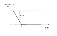
In the present embodiment, as illustrated in FIG. 9, the example in which the pressure increase speed calculation unit 105 adjusts the pressure increase speed of the brake oil according to the length of the elapsed time after the stop determination has been described. is not. Therefore, another configuration example of the boosting speed calculation unit 105 that adjusts the boosting speed of the brake oil will be described below.
図11は、本実施形態における昇圧速度演算部105の他の構成例を説明する図である。
FIG. 11 is a diagram for explaining another configuration example of the boosting speed calculation unit 105 in the present embodiment.
この例では、摩擦ブレーキ8a乃至8dに供給されるブレーキ油の昇圧速度と車速Vとの関係を示す昇圧速度テーブルが昇圧速度演算部105にあらかじめ記憶される。昇圧速度テーブルは、摩擦ブレーキ8a乃至8dの機械特性を考慮して電動車両100における前後加速度の発生を抑制するようにあらかじめ定められる。昇圧速度テーブルについては、図11に示すように車速Vが小さいなるほど、反比例曲線を描くように摩擦ブレーキ8a乃至8dの昇圧速度が徐々に大きくなる。
In this example, a boosting speed table indicating the relationship between the boosting speed of the brake oil supplied to the friction brakes 8 a to 8 d and the vehicle speed V is stored in advance in the boosting speed calculation unit 105. The step-up speed table is determined in advance so as to suppress the occurrence of longitudinal acceleration in the electric vehicle 100 in consideration of the mechanical characteristics of the friction brakes 8a to 8d. In the boosting speed table, as the vehicle speed V decreases as shown in FIG. 11, the boosting speeds of the friction brakes 8a to 8d gradually increase so as to draw an inversely proportional curve.
そして、昇圧速度演算部105は、車速Vを取得すると、図11に示した昇圧速度テーブルを参照して、取得した車速Vの値に関係付けられた昇圧速度を算出する。続いて昇圧速度演算部105は、算出した昇圧速度を、図9に示した昇圧速度切替器107に出力する。
When the vehicle speed V is acquired, the pressure increase speed calculation unit 105 calculates a pressure increase speed related to the value of the acquired vehicle speed V with reference to the pressure increase speed table shown in FIG. Subsequently, the boosting speed calculator 105 outputs the calculated boosting speed to the boosting speed switch 107 shown in FIG.
このように、車速Vの大きさに応じて摩擦ブレーキ8a乃至8dの昇圧速度を変更する昇圧速度演算部105であっても、電動車両100の前後加速度を抑制しつつ電動車両100を停止することができる。
As described above, even in the boosting speed calculation unit 105 that changes the boosting speed of the friction brakes 8a to 8d according to the magnitude of the vehicle speed V, the electric vehicle 100 is stopped while suppressing the longitudinal acceleration of the electric vehicle 100. Can do.
次に、本実施形態における電動車両100を停止する停止方法について説明する。
Next, a stop method for stopping the electric vehicle 100 in the present embodiment will be described.
図12は、図2に示したステップS205で行われる停止制御処理の処理手順例を示すフローチャートである。
FIG. 12 is a flowchart illustrating a processing procedure example of the stop control process performed in step S205 illustrated in FIG.
ステップS910においてブレーキコントローラ10は、電動車両100の車速Vを示す車両情報を取得する。
In step S910, the brake controller 10 acquires vehicle information indicating the vehicle speed V of the electric vehicle 100.
ステップS920においてモータコントローラ2は、主に路面勾配によって電動車両100に作用する重力を打ち消すための勾配トルク推定値Td*を算出する。
In step S920, the motor controller 2 calculates a gradient torque estimated value Td * for canceling the gravity acting on the electric vehicle 100 mainly by the road surface gradient.
ステップS930においてブレーキコントローラ10は、三相交流電流iu、iv、iwに基づいてモータ4に生じるトルクを示すモータトルクTmを演算する。
In step S930, the brake controller 10 calculates a motor torque Tm indicating a torque generated in the motor 4 based on the three-phase alternating currents iu, iv, iw.
ステップS940においてモータコントローラ2は、車速Vが停車閾値Th_s未満である否かを判断する。停車閾値Th_sは、電動車両100が停止するか否かを判定するための閾値である。モータコントローラ2は、車速Vが停車閾値Th_s以上である場合には、停止制御処理を終了して図2に示した電動車両100の制御方法に関する処理手順に戻る。
In step S940, the motor controller 2 determines whether or not the vehicle speed V is less than the stop threshold Th_s. The stop threshold value Th_s is a threshold value for determining whether or not the electric vehicle 100 stops. When the vehicle speed V is equal to or higher than the stop threshold Th_s, the motor controller 2 ends the stop control process and returns to the process procedure related to the control method of the electric vehicle 100 shown in FIG.
ステップS950においてモータコントローラ2は、車速Vが停車閾値Th_s未満である場合には、勾配トルク推定値Td*に基づいて、勾配の有無に拘わらず電動車両100が確実に停止するのに必要となる目標停止トルクTs_tを算出する。
In step S950, when the vehicle speed V is less than the stop threshold Th_s, the motor controller 2 is required to reliably stop the electric vehicle 100 regardless of the presence or absence of the gradient based on the gradient torque estimated value Td *. A target stop torque Ts_t is calculated.
ステップS960において、ブレーキコントローラ10は、摩擦ブレーキ8a乃至8dの応答性を確保するために摩擦初期トルクTf_iを設定する。本実施形態のブレーキコントローラ10は、ステップS930で演算されたモータトルクTmの値を摩擦初期トルクTf_iとして設定する。
In step S960, the brake controller 10 sets the initial friction torque Tf_i in order to ensure the responsiveness of the friction brakes 8a to 8d. The brake controller 10 of the present embodiment sets the value of the motor torque Tm calculated in step S930 as the initial friction torque Tf_i.
そして、ブレーキコントローラ10は、摩擦トルクTfが摩擦初期トルクTf_iに到達するよう、図9に示した昇圧速度上限設定部106で設定される昇圧速度の上限値により、摩擦ブレーキ8a乃至8dに供給される液体の圧力(ブレーキ液圧)を上昇させる。これにより、摩擦ブレーキ8a乃至8dの応答性を確保することができ、摩擦トルクTfを精度よく調整することが可能になる。
Then, the brake controller 10 is supplied to the friction brakes 8a to 8d by the upper limit value of the boost speed set by the boost speed upper limit setting unit 106 shown in FIG. 9 so that the friction torque Tf reaches the initial friction torque Tf_i. Increase the pressure of the fluid (brake fluid pressure). Thereby, the responsiveness of the friction brakes 8a to 8d can be ensured, and the friction torque Tf can be adjusted with high accuracy.
ステップS970においてブレーキコントローラ10は、電動車両100に用いられる制動トルクを、モータトルクTmから摩擦トルクTfに切り替える。例えば、摩擦トルクTfが摩擦初期トルクTf_iまで上昇したときには、ブレーキコントローラ10は、摩擦トルクTfが目標停止トルクTs_tに到達するようブレーキ液圧を徐々に上昇させるとともに、モータトルクTmを徐々に低下させる。これにより、電動車両100の前後加速度の発生を抑制しつつ、モータ4の消費電力を低減することができる。
In step S970, the brake controller 10 switches the braking torque used for the electric vehicle 100 from the motor torque Tm to the friction torque Tf. For example, when the friction torque Tf increases to the initial friction torque Tf_i, the brake controller 10 gradually increases the brake fluid pressure and gradually decreases the motor torque Tm so that the friction torque Tf reaches the target stop torque Ts_t. . Thereby, the power consumption of the motor 4 can be reduced while suppressing the occurrence of longitudinal acceleration of the electric vehicle 100.
ステップS980においてブレーキコントローラ10は、図10(d)に示すように、摩擦トルクTfが摩擦初期トルクTf_iから目標停止トルクTs_tまで上昇するのに、摩擦ブレーキ8a乃至8dの昇圧速度を調整する。
In step S980, the brake controller 10 adjusts the pressure increase speeds of the friction brakes 8a to 8d as the friction torque Tf increases from the friction initial torque Tf_i to the target stop torque Ts_t, as shown in FIG. 10 (d).
例えば、ブレーキコントローラ10は、図9の昇圧速度演算部105に示したように、電動車両100が停止すると判定してからの経過時間に応じて昇圧速度を徐々に大きくする。あるいは、ブレーキコントローラ10は、図11に示した昇圧速度テーブルを用いて、車速Vの低下に応じて昇圧速度を徐々に大きくするものであってもよい。
For example, the brake controller 10 gradually increases the boosting speed according to the elapsed time since it is determined that the electric vehicle 100 stops, as shown in the boosting speed calculation unit 105 of FIG. Alternatively, the brake controller 10 may gradually increase the boosting speed as the vehicle speed V decreases using the boosting speed table shown in FIG.
これにより、電動車両100の前後加速度を抑制しつつ電動車両100を滑らかに停止することができる。
Thereby, the electric vehicle 100 can be smoothly stopped while suppressing the longitudinal acceleration of the electric vehicle 100.
本発明の第1実施形態によれば、電動車両100は、電動車両100に回生制動力を与えるモータ4と、電動車両100に摩擦制動力を与える摩擦制動機構を構成する摩擦ブレーキ8a乃至8dとを備える。図2に示したように、電動車両100の制御方法は、アクセルペダルの操作量を示すアクセル開度APに基づいてモータ4のトルク目標値Tm_tを示す目標トルクを演算するステップS202と、路面の勾配による外乱を打ち消す勾配トルクを推定するステップS203とを含む。外乱とは、主に、路面の勾配により外部から電動車両100に作用する重力のことである。
According to the first embodiment of the present invention, the electric vehicle 100 includes a motor 4 that applies a regenerative braking force to the electric vehicle 100, and friction brakes 8a to 8d that constitute a friction braking mechanism that applies a friction braking force to the electric vehicle 100. Is provided. As shown in FIG. 2, the method for controlling the electric vehicle 100 includes a step S202 of calculating a target torque indicating a torque target value Tm_t of the motor 4 based on an accelerator opening AP indicating an operation amount of an accelerator pedal, And step S203 for estimating a gradient torque that cancels disturbance due to the gradient. The disturbance is mainly gravity that acts on the electric vehicle 100 from the outside due to the gradient of the road surface.
さらに、電動車両100の制御方法は、推定した勾配トルク推定値Td*とトルク目標値Tm_tとに基づいてモータトルク指令値Tm*を演算するステップ204と、モータトルク指令値Tm*に基づいてモータ4に生じるモータトルクTmを制御するステップS206乃至S208とを含む。そして電動車両100の制御方法は、電動車両100が停止するときには、電動車両100に与えられる制動トルクを勾配トルク推定値Td*よりも大きな値とし、その制動トルクをモータトルクTmから摩擦ブレーキ8a乃至8dの摩擦トルクTfに切り替えるステップS205を備える。ここにいう摩擦トルクTfは、摩擦ブレーキ8a乃至8dにより生じる摩擦制動力をモータ4の駆動軸のトルクに換算したパラメータである。
Furthermore, the control method of the electric vehicle 100 includes a step 204 of calculating a motor torque command value Tm * based on the estimated gradient torque estimated value Td * and the torque target value Tm_t, and a motor based on the motor torque command value Tm *. 4 and steps S206 to S208 for controlling the motor torque Tm generated in step S4. The electric vehicle 100 is controlled such that when the electric vehicle 100 stops, the braking torque applied to the electric vehicle 100 is set to a value larger than the gradient torque estimated value Td *, and the braking torque is calculated from the motor torque Tm to the friction brakes 8a to 8b. Step S205 for switching to the friction torque Tf of 8d is provided. Here, the friction torque Tf is a parameter obtained by converting the friction braking force generated by the friction brakes 8 a to 8 d into torque of the drive shaft of the motor 4.
このように、制御装置110は、電動車両100が停止間際になると、電動車両100に与える制動力をモータ4の制動力から摩擦制動力に切り替え、勾配トルク推定値Td*よりも大きな摩擦トルクTfを用いて電動車両100を停止させる。
Thus, when the electric vehicle 100 is about to stop, the control device 110 switches the braking force applied to the electric vehicle 100 from the braking force of the motor 4 to the friction braking force, and the friction torque Tf larger than the gradient torque estimated value Td *. The electric vehicle 100 is stopped using.
このようにする理由は、例えば電動車両100の乗員数や積載量などの増減により、勾配トルクの推定で用いられる電動車両100の重量の設定値と実際値とのズレ幅が大きくなると、勾配トルク推定値Td*の誤差が大きくなる。その結果、勾配のある路面でモータトルクTmを用いて停車する電動車両では、モータトルク指令値Tm*の誤差が大きくなって電動車両100の制動力が不足することから、滑らかに停車することが困難になる。
The reason for this is that, for example, if the deviation width between the set value of the weight of the electric vehicle 100 used in the estimation of the gradient torque and the actual value increases due to increase or decrease in the number of passengers or the load capacity of the electric vehicle 100, the gradient torque The error of the estimated value Td * increases. As a result, in an electric vehicle that stops using a motor torque Tm on a sloped road surface, the error of the motor torque command value Tm * becomes large and the braking force of the electric vehicle 100 is insufficient, so that the vehicle can stop smoothly. It becomes difficult.
この対策として、電動車両100の重量変動により勾配トルク推定値Td*の誤差が大きくなったとしても、電動車両100の制動トルクを摩擦トルクTfに切り替えてその摩擦トルクTfを勾配トルク推定値Td*よりも増加させる。これにより、登坂路や降坂路であっても、電動車両100の重量などの勾配トルク推定用パラメータの変動に拘わらず、電動車両100を停止させることができる。
As a countermeasure, even if the error of the gradient torque estimated value Td * increases due to the weight variation of the electric vehicle 100, the braking torque of the electric vehicle 100 is switched to the friction torque Tf, and the friction torque Tf is changed to the gradient torque estimated value Td *. Than to increase. Thus, even on an uphill road or a downhill road, the electric vehicle 100 can be stopped regardless of fluctuations in the gradient torque estimation parameters such as the weight of the electric vehicle 100.
すなわち、本実施形態によれば、車両が走行する路面勾配の変化にかかわらず、車両を停止させることができる。
That is, according to this embodiment, the vehicle can be stopped regardless of the change in the road surface gradient on which the vehicle travels.
また、本実施形態によれば、ステップS205において、電動車両100が停止するか否かをモータコントローラ2が判定する。そして電動車両100が停止すると判定された場合には、ブレーキコントローラ10が、電動車両100の運転状態に応じて摩擦トルクTfの増加速度を制御する。
Further, according to the present embodiment, in step S205, the motor controller 2 determines whether or not the electric vehicle 100 is stopped. When it is determined that the electric vehicle 100 is stopped, the brake controller 10 controls the increasing speed of the friction torque Tf according to the operating state of the electric vehicle 100.
例えば、ブレーキコントローラ10は、電動車両100が停止すると判定してからの経過時間に応じて、摩擦ブレーキ8a乃至8dに供給される液体の昇圧速度を大きくする。これにより、停車を判定してから時間が経過するにつれて昇圧速度が大きくなるので、ドライバに違和感を与えることなく、簡易な手法により電動車両100を滑らかに停止させることができる。
For example, the brake controller 10 increases the pressure increase speed of the liquid supplied to the friction brakes 8a to 8d according to the elapsed time after determining that the electric vehicle 100 stops. As a result, the pressure increase speed increases as time elapses after the stop is determined, so that the electric vehicle 100 can be smoothly stopped by a simple method without giving the driver a sense of incongruity.
あるいは、ブレーキコントローラ10は、電動車両100の速度である車速Vの低下に応じて、摩擦ブレーキ8a乃至8dに供給される液体の昇圧速度を大きくするものであってもよい。この場合であっても、車速Vが低下するにつれて昇圧速度が大きくなるので、上述の手法と同じように、電動車両100を滑らかに停止させることができる。
Alternatively, the brake controller 10 may increase the pressure increase speed of the liquid supplied to the friction brakes 8a to 8d in accordance with a decrease in the vehicle speed V that is the speed of the electric vehicle 100. Even in this case, since the pressure increase speed increases as the vehicle speed V decreases, the electric vehicle 100 can be smoothly stopped as in the above-described method.
このように、停車判定後の経過時間や車速Vなどの電動車両100の運転状態に応じて摩擦トルクTfの増加速度を調整することにより、摩擦制動力を用いて電動車両100を滑らかに停止させることができる。
Thus, the electric vehicle 100 is smoothly stopped using the friction braking force by adjusting the increasing speed of the friction torque Tf according to the elapsed time after the stoppage determination and the driving state of the electric vehicle 100 such as the vehicle speed V. be able to.
また、本実施形態によれば、ステップS205において、ブレーキコントローラ10は、電動車両100が停止すると判定した場合には、摩擦トルクTfがモータトルクTmと一致するように摩擦ブレーキ8a乃至8dにおける液体の圧力を速やかに上昇させる。その後、ブレーキコントローラ10は、摩擦ブレーキ8a乃至8dにおける液体の昇圧速度を徐々に大きくする。
Further, according to the present embodiment, in step S205, when the brake controller 10 determines that the electric vehicle 100 is stopped, the liquid in the friction brakes 8a to 8d is adjusted so that the friction torque Tf matches the motor torque Tm. Increase pressure quickly. Thereafter, the brake controller 10 gradually increases the liquid pressurization speed in the friction brakes 8a to 8d.
このように、摩擦ブレーキ8a乃至8dの昇圧速度を調整する前に摩擦ブレーキ8a乃至8dに供給される液体の圧力を上昇させておくことで、摩擦ブレーキ8a乃至8dから摩擦制動力が発生しやすい状態になるので、摩擦制動力の応答性を確保することができる。したがって、精度よく摩擦トルクTfの増加速度が調整されるので、滑らかな停車を実現することができる。
As described above, the friction braking force is easily generated from the friction brakes 8a to 8d by increasing the pressure of the liquid supplied to the friction brakes 8a to 8d before adjusting the pressure increase speed of the friction brakes 8a to 8d. As a result, the responsiveness of the friction braking force can be ensured. Accordingly, since the increasing speed of the friction torque Tf is adjusted with high accuracy, a smooth stop can be realized.
また、本実施形態によれば、ステップS205において、モータコントローラ2が車速Vに比例するパラメータが停車閾値Th_sよりも低下するか否かを判断する。そして車速Vに比例するパラメータが停車閾値Th_sよりも低下した場合には、ブレーキコントローラ10が摩擦トルクTfを勾配トルク推定値Td*の絶対値よりも大きな目標停止トルクTs_tまで増加させる。
Further, according to the present embodiment, in step S205, the motor controller 2 determines whether or not the parameter proportional to the vehicle speed V is lower than the stop threshold Th_s. When the parameter proportional to the vehicle speed V decreases below the stop threshold Th_s, the brake controller 10 increases the friction torque Tf to a target stop torque Ts_t that is larger than the absolute value of the gradient torque estimated value Td *.
これにより、電動車両100が停止するときに摩擦トルクTfが勾配トルク推定値Td*よりも大きな値に設定されるので、ドライバに与える違和感を軽減しつつ電動車両100を確実に停止させることができる。
Thereby, when the electric vehicle 100 stops, the friction torque Tf is set to a value larger than the gradient torque estimated value Td *, so that the electric vehicle 100 can be reliably stopped while reducing the uncomfortable feeling given to the driver. .
特に本実施形態では、目標停止トルクTs_tは、摩擦ブレーキ8a乃至8dに供給される液体の温度特性によりあらかじめ設定される。摩擦ブレーキ8a乃至8dにおける液体の温度が高くなるほど摩擦制動力が低下する温度特性を有していることから、目標停止トルクTs_tは、液体の温度が上昇したとしても確実に電動車両100が停止するような値に設定される。これにより、登坂路や降坂路において電動車両100が停止することなくずり下がる(流動する)ことを抑制することができる。
Particularly in the present embodiment, the target stop torque Ts_t is set in advance according to the temperature characteristics of the liquid supplied to the friction brakes 8a to 8d. Since the friction braking force decreases as the liquid temperature in the friction brakes 8a to 8d increases, the target stop torque Ts_t reliably stops the electric vehicle 100 even if the liquid temperature increases. It is set to such a value. Thereby, it is possible to suppress the electric vehicle 100 from sliding down (flowing) without stopping on the uphill road or downhill road.
また、本実施形態によれば、目標停止トルクTs_tは、摩擦トルクTfが電動車両100の発進性を確保可能な範囲で設定される。摩擦ブレーキ8a乃至8dにおける液圧を高くするほど、電動車両100の次回発進時における摩擦ブレーキ8a乃至8dの液圧を下げるのに時間を要する。その結果、電動車両100の発進性が低下する。
Further, according to the present embodiment, the target stop torque Ts_t is set in a range in which the friction torque Tf can ensure the startability of the electric vehicle 100. The higher the hydraulic pressure in the friction brakes 8a to 8d, the longer it takes to lower the hydraulic pressure in the friction brakes 8a to 8d when the electric vehicle 100 starts next time. As a result, the startability of the electric vehicle 100 is reduced.
この対策として、目標停止トルクTs_tを電動車両100の発進性を確保可能な範囲内に設定することにより、登坂路や降板路を走行する電動車両100における滑らかな停止と速やかな発進とを両立することができる。
As a countermeasure, by setting the target stop torque Ts_t within a range in which the startability of the electric vehicle 100 can be secured, both smooth stop and quick start in the electric vehicle 100 traveling on an uphill road or a downhill road can be achieved. be able to.
(第2実施形態)
図13は、本発明の第2実施形態における勾配トルク演算部22の構成例を示すブロック図である。
(Second Embodiment)
FIG. 13 is a block diagram illustrating a configuration example of the gradient torque calculation unit 22 in the second embodiment of the present invention.
本実施形態の勾配トルク演算部22は、登坂路や降坂路を走行している電動車両100のドライバに対して違和感を与えないよう、図6に示した制御ブロック225からの勾配トルク推定値Td*を補正する。この勾配トルク演算部22は、図6に示した各構成(221乃至225)に加えて、パーキングブレーキ検出部226と、第1ゲイン設定部227と、第2ゲイン算出部228と、マックスセレクト229と、勾配トルク補正部230とを含む。
The gradient torque calculation unit 22 of the present embodiment does not give a sense of incongruity to the driver of the electric vehicle 100 traveling on the uphill road or downhill road, and the estimated gradient torque value Td from the control block 225 shown in FIG. * Is corrected. The gradient torque calculation unit 22 includes a parking brake detection unit 226, a first gain setting unit 227, a second gain calculation unit 228, and a max select 229 in addition to the components (221 to 225) illustrated in FIG. And a gradient torque correction unit 230.
パーキングブレーキ検出部226は、パーキングブレーキ9c及び9dの作動状態を検出する。パーキングブレーキ検出部226は、検出したパーキングブレーキ9c及び9dの状態を示す検出信号PBを第1ゲイン設定部227に出力する。
The parking brake detector 226 detects the operating state of the parking brakes 9c and 9d. The parking brake detection unit 226 outputs a detection signal PB indicating the detected state of the parking brakes 9c and 9d to the first gain setting unit 227.
例えば、パーキングブレーキ9c及び9dが作動して従属輪7c及び7dに摩擦制動力を与えている状態では、パーキングブレーキ検出部226は、パーキングブレーキ9c及び9dのオン状態を示す検出信号PBを出力する。一方、パーキングブレーキ9c及び9dの作動が解除されて従属輪7c及び7dに摩擦制動力を与えていない状態では、パーキングブレーキ検出部226は、パーキングブレーキ9c及び9dのオフ状態を示す検出信号PBを出力する。
For example, in a state where the parking brakes 9c and 9d are activated and a friction braking force is applied to the dependent wheels 7c and 7d, the parking brake detection unit 226 outputs a detection signal PB indicating the on state of the parking brakes 9c and 9d. . On the other hand, in a state where the operation of the parking brakes 9c and 9d is released and no friction braking force is applied to the dependent wheels 7c and 7d, the parking brake detection unit 226 generates a detection signal PB indicating an off state of the parking brakes 9c and 9d. Output.
第1ゲイン設定部227は、パーキングブレーキ検出部226から出力される検出信号PBに応じて、勾配トルク推定値Td*を補正するための第1ゲインK1をマックスセレクト229に出力する。第1ゲインK1は、0.0から1.0までの範囲内の値に設定される。
The first gain setting unit 227 outputs a first gain K1 for correcting the gradient torque estimated value Td * to the max select 229 in accordance with the detection signal PB output from the parking brake detection unit 226. The first gain K1 is set to a value within a range from 0.0 to 1.0.
第1ゲインK1は、勾配トルク推定値Td*に応じて変化する可変値であってもよい。この場合には、勾配トルク推定値Td*が正(プラス)又は負(マイナス)に大きくなるほど、第1ゲインK1は小さな値に設定される。あるいは、勾配トルク推定値Td*は、例えば0.5などの固定値であってもよい。
The first gain K1 may be a variable value that changes according to the gradient torque estimated value Td *. In this case, the first gain K1 is set to a smaller value as the gradient torque estimated value Td * increases to a positive (plus) or negative (minus) value. Alternatively, the gradient torque estimated value Td * may be a fixed value such as 0.5.
仮に、第1ゲインK1が1.0に設定されると、勾配抵抗に起因する外乱の全部が勾配トルク推定値Td*によって相殺されることから、電動車両100は、勾配のない平坦路を走行した場合と同じように走行する。このため、ドライバによるアクセルペダルの操作量は、平地での操作量と同じになる。
If the first gain K1 is set to 1.0, the entire disturbance caused by the gradient resistance is canceled out by the gradient torque estimated value Td *, so the electric vehicle 100 travels on a flat road without a gradient. Travel the same way as you did. For this reason, the amount of operation of the accelerator pedal by the driver is the same as the amount of operation on flat ground.
しかしながら、内燃機関を駆動源とする内燃機関自動車をドライバが運転して登坂路や降坂路を走行する場合は、平坦路と同じような走行をしようとすると、アクセルペダルの操作量は平地での操作量に対して変化する。このため、第1ゲインK1が1.0に設定されると、内燃機関自動車との操作性の違いが原因となり、登坂路や降坂路では電動車両100のドライバに違和感を与えることになる。
However, when the driver drives an internal combustion engine vehicle with an internal combustion engine as a drive source and travels on an uphill road or a downhill road, the amount of operation of the accelerator pedal is flat on a flat ground. It changes with the amount of operation. For this reason, when the first gain K1 is set to 1.0, a difference in operability with the internal combustion engine automobile is caused, and the driver of the electric vehicle 100 is given a sense of incongruity on an uphill road or a downhill road.
この対策として、勾配トルク推定値Td*が0(ゼロ)を含む所定範囲を超えている場合、すなわち道路が登坂路又は降坂路である場合には、第1ゲインK1を1.0よりも小さな値に設定するのが望ましい。そして勾配トルク推定値Td*が所定範囲内にある場合には、第1ゲインK1が1.0に設定されるようにしてもよい。
As a countermeasure, when the estimated gradient torque value Td * exceeds a predetermined range including 0 (zero), that is, when the road is an uphill road or a downhill road, the first gain K1 is smaller than 1.0. It is desirable to set it to a value. If the estimated gradient torque value Td * is within a predetermined range, the first gain K1 may be set to 1.0.
このように、第1ゲイン設定部227は、パーキングブレーキ9c及び9dのオフ状態を示す検出信号PBを受信すると、勾配トルク推定値Td*を補正するために第1ゲインK1をマックスセレクト229に出力する。
As described above, when receiving the detection signal PB indicating the OFF state of the parking brakes 9c and 9d, the first gain setting unit 227 outputs the first gain K1 to the max select 229 in order to correct the gradient torque estimated value Td *. To do.
一方、第1ゲイン設定部227は、パーキングブレーキ9c及び9dのオン状態を示す検出信号PBを受信すると、マックスセレクト229に対して0(ゼロ)を出力する。
On the other hand, when receiving the detection signal PB indicating the on state of the parking brakes 9c and 9d, the first gain setting unit 227 outputs 0 (zero) to the max select 229.
パーキングブレーキ9c及び9dが作動している状態においては、勾配抵抗だけでなくパーキングブレーキ9c及び9dによる摩擦制動力が電動車両100に作用した状態で勾配トルク推定値Td*が算出される。この勾配トルク推定値Td*には、パーキングブレーキ9c及び9dによる制動トルクを打ち消す成分が含まれており、勾配トルク推定値Td*を第1ゲインK1で補正してしまうと、補正した分だけパーキングブレーキ9c及び9dによる制動トルクを打ち消すことができなくなる。その結果、ドライバの意図するような制動を行えなくなることが懸念される。この対策として、第1ゲイン設定部227は、オン状態を示す検出信号PBを受信した場合に、勾配トルク推定値Td*の補正が行われないように0をマックスセレクト229に出力する。
In the state where the parking brakes 9c and 9d are operating, the gradient torque estimated value Td * is calculated in a state where not only the gradient resistance but also the friction braking force by the parking brakes 9c and 9d is applied to the electric vehicle 100. The gradient torque estimated value Td * includes a component that cancels the braking torque by the parking brakes 9c and 9d. If the gradient torque estimated value Td * is corrected by the first gain K1, parking is performed by the corrected amount. It becomes impossible to cancel the braking torque by the brakes 9c and 9d. As a result, there is a concern that braking as intended by the driver cannot be performed. As a countermeasure, when the first gain setting unit 227 receives the detection signal PB indicating the ON state, the first gain setting unit 227 outputs 0 to the max select 229 so that the gradient torque estimated value Td * is not corrected.
第2ゲイン算出部228は、停車間際に電動車両100が確実に停止するよう、あらかじめ定められた演算式やゲインテーブルなどを用いて、勾配トルク推定値Td*を補正するための第2ゲインK2を算出する。第2ゲイン算出部228は、車速Vが小さくなるほど、第2ゲインK2を大きな値に設定する。
The second gain calculation unit 228 uses a predetermined arithmetic expression, a gain table, or the like to correct the gradient torque estimated value Td * so as to ensure that the electric vehicle 100 stops immediately before stopping. Is calculated. The second gain calculation unit 228 sets the second gain K2 to a larger value as the vehicle speed V decreases.
例えば、第2ゲイン算出部228は、ゲインテーブルを参照して、車速Vが0に近づくほど、第2ゲインK2を1.0に近づける。これにより、車速Vが0になった場合には、第2ゲインK2が1.0に設定されるので、勾配トルク推定値Td*が小さく補正されず、電動車両100の制動力が不足するという事態を回避することができる。
For example, the second gain calculation unit 228 refers to the gain table and brings the second gain K2 closer to 1.0 as the vehicle speed V approaches zero. Thereby, when the vehicle speed V becomes 0, the second gain K2 is set to 1.0, so that the gradient torque estimated value Td * is not corrected small, and the braking force of the electric vehicle 100 is insufficient. The situation can be avoided.
さらに、パーキングブレーキ9c及び9dが作動している状態であっても、一般的に車速Vは小さく勾配トルク推定値Td*の補正量が小さくなることから、パーキングブレーキ9c及び9dによる制動トルクが概ね打ち消される。このため、ドライバに与える違和感を軽減しつつ電動車両100を滑らかに停止することが可能なる。
Further, even when the parking brakes 9c and 9d are in operation, the vehicle speed V is generally small and the correction amount of the gradient torque estimation value Td * is small, so that the braking torque by the parking brakes 9c and 9d is almost equal. Be countered. For this reason, it is possible to smoothly stop the electric vehicle 100 while reducing the uncomfortable feeling given to the driver.
また、第2ゲイン算出部228は、算出した第2ゲインK2をマックスセレクト229に出力する。なお、第2ゲイン算出部228に設定されるゲインテーブルについては図14を参照して後述する。
Further, the second gain calculation unit 228 outputs the calculated second gain K2 to the max select 229. The gain table set in the second gain calculation unit 228 will be described later with reference to FIG.
マックスセレクト229は、第1ゲイン設定部227から出力される第1ゲインK1と、第2ゲイン算出部228から出力される第2ゲインK2と、のうち大きい方の値を勾配トルク補正部230に出力する。
The max select 229 supplies the larger value of the first gain K1 output from the first gain setting unit 227 and the second gain K2 output from the second gain calculation unit 228 to the gradient torque correction unit 230. Output.
勾配トルク補正部230は、マックスセレクト229の出力値に基づいて、制御ブロック225からの勾配トルク推定値Td*を補正する。本実施形態の勾配トルク補正部230は、マックスセレクト229から出力されるゲインを勾配トルク推定値Td*に乗じた値を新たな勾配トルク推定値Td*として算出する。勾配トルク補正部230は、算出した勾配トルク推定値Td*を、図3に示した指令トルク演算部23及び目標停止トルク演算部25にそれぞれ出力する。
The gradient torque correction unit 230 corrects the gradient torque estimated value Td * from the control block 225 based on the output value of the max select 229. The gradient torque correction unit 230 of the present embodiment calculates a value obtained by multiplying the gradient torque estimated value Td * by the gain output from the max select 229 as a new gradient torque estimated value Td *. The gradient torque correction unit 230 outputs the calculated gradient torque estimated value Td * to the command torque calculation unit 23 and the target stop torque calculation unit 25 shown in FIG.
図14は、第2ゲイン算出部228に保持されるゲインテーブルの一例を説明する観念図である。この例では縦軸が第2ゲインK2を示し、横軸が車速Vを示す。
FIG. 14 is a conceptual diagram illustrating an example of a gain table held in the second gain calculation unit 228. In this example, the vertical axis indicates the second gain K2, and the horizontal axis indicates the vehicle speed V.
図14に示すように、車速Vが所定の速度V1よりも小さくなるほど、第2ゲインK2が大きくなるように設定されている。すなわち、電動車両100が停止間際になると、勾配トルク推定値Td*の補正量が小さくなる。これにより、電動車両100を確実に停止することが可能になる。
As shown in FIG. 14, the second gain K2 is set to increase as the vehicle speed V becomes lower than the predetermined speed V1. That is, when electric vehicle 100 is about to stop, the correction amount of gradient torque estimated value Td * decreases. Thereby, it becomes possible to stop electrically powered vehicle 100 reliably.
一方、車速Vが所定の速度V1よりも大きい領域においては、マックスセレクト229で第1ゲインK1が選択されるように、第2ゲインK2が0に設定されている。これにより、第1ゲインK1により勾配トルク推定値Td*が補正されるので、登坂路や降坂路における電動車両100の操作性が内燃機関自動車の操作性と比較して同等になるため、電動車両100のドライバに与える違和感を軽減することができる。
On the other hand, in the region where the vehicle speed V is higher than the predetermined speed V1, the second gain K2 is set to 0 so that the first gain K1 is selected by the max select 229. As a result, the estimated gradient torque value Td * is corrected by the first gain K1, so that the operability of the electric vehicle 100 on the uphill road and the downhill road is equivalent to the operability of the internal combustion engine automobile. The uncomfortable feeling given to 100 drivers can be reduced.
本発明の第2実施形態によれば、勾配トルク補正部230は、勾配トルク推定値Td*を減少補正する。そして勾配トルク補正部230は、電動車両100が停車間際になると、車速Vが減少するほど勾配トルク推定値Td*の補正量を0(ゼロ)に近づける。これにより、登坂路や降坂路を走行している電動車両100のドライバに与える違和感を軽減しつつ、電動車両100を滑らかに、かつ、確実に停止させることができる。
According to the second embodiment of the present invention, the gradient torque correction unit 230 corrects the gradient torque estimated value Td * by decreasing it. When the electric vehicle 100 is about to stop, the gradient torque correction unit 230 brings the correction amount of the gradient torque estimated value Td * closer to 0 (zero) as the vehicle speed V decreases. As a result, the electric vehicle 100 can be smoothly and reliably stopped while reducing the uncomfortable feeling given to the driver of the electric vehicle 100 traveling on the uphill road or downhill road.
また、本実施形態によれば、勾配トルク補正部230は、勾配トルク推定値Td*が増加するほど、勾配トルク推定値Td*を減少補正する。これにより、電動車両100の操作性が、内燃機関自動車の操作性により一層近づくことになるので、ドライバに与える違和感をさらに軽減することができる。
Further, according to the present embodiment, the gradient torque correction unit 230 corrects the gradient torque estimated value Td * so as to decrease as the gradient torque estimated value Td * increases. As a result, the operability of the electric vehicle 100 becomes closer to the operability of the internal combustion engine automobile, so that the uncomfortable feeling given to the driver can be further reduced.
さらに、本実施形態によれば、パーキングブレーキ検出部226がオン状態を示す検出信号PBを出力する場合は、第1ゲイン設定部227から第1ゲインK1の代わりに0が出力されるので、勾配トルク補正部230は、第1ゲインK1に基づく補正を行わない。すなわち、勾配トルク補正部230は、パーキングブレーキ9c及び9dから電動車両100に摩擦制動力が与えられている場合には、勾配トルク推定値Td*の補正を抑制する。
Furthermore, according to the present embodiment, when the parking brake detection unit 226 outputs the detection signal PB indicating the on state, the first gain setting unit 227 outputs 0 instead of the first gain K1, so that the gradient The torque correction unit 230 does not perform correction based on the first gain K1. That is, gradient torque correction unit 230 suppresses correction of gradient torque estimated value Td * when friction braking force is applied to electric vehicle 100 from parking brakes 9c and 9d.
これにより、パーキングブレーキ9c及び9dが作動している状態であっても、パーキングブレーキ9c及び9dによる制動トルクが打ち消されるので、ドライバに違和感を与えることなく電動車両100を滑らかに停止させることができる。
Thus, even when the parking brakes 9c and 9d are in operation, the braking torque by the parking brakes 9c and 9d is canceled out, so that the electric vehicle 100 can be smoothly stopped without causing the driver to feel uncomfortable. .
(第3実施形態)
図15は、本発明の第3実施形態における勾配トルク演算部22の構成例を示すブロック図である。
(Third embodiment)
FIG. 15 is a block diagram illustrating a configuration example of the gradient torque calculation unit 22 in the third embodiment of the present invention.
本実施形態における勾配トルク演算部22は、電動車両100がスリップ状態であると判定した場合には、勾配トルク推定値Td*を制限する。この勾配トルク演算部22は、図13に示した各構成(226乃至230)に加えて、駆動輪速度算出部231と、従属輪速度算出部232と、スリップ判定部233と、マスク設定部234と、勾配トルク制限部235とを含む。
The gradient torque calculation unit 22 in the present embodiment limits the gradient torque estimated value Td * when it is determined that the electric vehicle 100 is in the slip state. The gradient torque calculation unit 22 includes a driving wheel speed calculation unit 231, a dependent wheel speed calculation unit 232, a slip determination unit 233, and a mask setting unit 234 in addition to the components (226 to 230) illustrated in FIG. And a gradient torque limiting unit 235.
駆動輪速度算出部231は、車輪速センサ13a及び13bの検出値を用いて、駆動輪7a及び7bに関する速度を算出する。本実施形態の駆動輪速度算出部231は、車輪速センサ13a及び13bの各検出値を用いて、駆動輪7a及び7bの平均速度WS1aveを算出する。
The driving wheel speed calculation part 231 calculates the speed regarding the driving wheels 7a and 7b using the detected values of the wheel speed sensors 13a and 13b. The drive wheel speed calculation unit 231 of the present embodiment calculates the average speed WS1ave of the drive wheels 7a and 7b using the detected values of the wheel speed sensors 13a and 13b.
駆動輪速度算出部231は、駆動輪7a及び7bの平均速度WS1aveをスリップ判定部233に出力する。なお、駆動輪速度算出部231は、駆動輪7a及び7bのうちいずれかの速度を出力するものであってもよい。
The driving wheel speed calculation unit 231 outputs the average speed WS1ave of the driving wheels 7a and 7b to the slip determination unit 233. The driving wheel speed calculation unit 231 may output one of the driving wheels 7a and 7b.
従属輪速度算出部232は、車輪速センサ13c及び13dの検出値を用いて、従属輪7c及び7dに関する速度を算出する。本実施形態の従属輪速度算出部232は、車輪速センサ13c及び13dの各検出値を用いて、従属輪7c及び7dの平均速度WS2aveを算出する。
The dependent wheel speed calculation unit 232 calculates the speed related to the dependent wheels 7c and 7d using the detection values of the wheel speed sensors 13c and 13d. The dependent wheel speed calculation unit 232 of the present embodiment calculates the average speed WS2ave of the dependent wheels 7c and 7d using the detected values of the wheel speed sensors 13c and 13d.
従属輪速度算出部232は、従属輪7c及び7dの平均速度WS2aveをスリップ判定部233に出力する。なお、従属輪速度算出部232は、従属輪7c及び7dのうちいずれかの速度を出力するものであってもよい。
The dependent wheel speed calculation unit 232 outputs the average speed WS2ave of the dependent wheels 7c and 7d to the slip determination unit 233. The dependent wheel speed calculation unit 232 may output one of the dependent wheels 7c and 7d.
スリップ判定部233は、電動車両100がスリップ状態か否かを判定し、判定した結果を勾配トルク制限部235に出力する。
The slip determination unit 233 determines whether or not the electric vehicle 100 is in a slip state, and outputs the determined result to the gradient torque limiting unit 235.
本実施形態のスリップ判定部233は、駆動輪7a及び7bの平均速度WS1aveと、従属輪7c及び7dの平均速度WS2aveとに基づいて、電動車両100のスリップ率を算出する。本実施形態のスリップ判定部233は、次式(14)に従って、スリップ率Rsを算出する。
The slip determination unit 233 of the present embodiment calculates the slip ratio of the electric vehicle 100 based on the average speed WS1ave of the drive wheels 7a and 7b and the average speed WS2ave of the dependent wheels 7c and 7d. The slip determination unit 233 of the present embodiment calculates the slip rate Rs according to the following equation (14).
そしてスリップ判定部233は、スリップ率Rsの絶対値がスリップ閾値を超えるか否かを判断する。スリップ閾値は、例えば、実験やシミュレーションなどの結果を通じてあらかじめ設定される。
The slip determination unit 233 determines whether or not the absolute value of the slip rate Rs exceeds the slip threshold. For example, the slip threshold is set in advance through a result of an experiment or a simulation.
スリップ率Rsがスリップ閾値よりも大きい場合には、スリップ判定部233は、電動車両100がスリップ状態、いわゆる低μ状態であると判定し、「1」を示す判定信号を勾配トルク制限部235に出力する。一方、スリップ率Rsがスリップ閾値以下である場合には、スリップ判定部233は、電動車両100がスリップ状態ではないと判定し、「0」を示す判定信号を勾配トルク制限部235に出力する。
When the slip ratio Rs is larger than the slip threshold, the slip determination unit 233 determines that the electric vehicle 100 is in a slip state, that is, a so-called low μ state, and sends a determination signal indicating “1” to the gradient torque limiting unit 235. Output. On the other hand, when the slip rate Rs is equal to or less than the slip threshold, the slip determination unit 233 determines that the electric vehicle 100 is not in the slip state, and outputs a determination signal indicating “0” to the gradient torque limiting unit 235.
また、スリップ判定部233は、電動車両100がスリップ状態であると判定した後、所定期間だけ判定を停止するタイマ処理や、3回連続して同一の判定結果が得られるまで判定信号の出力を停止する三連照合処理などを行う。これにより、判定信号が「0」と「1」との間で頻繁に切り替わるハンチング現象の発生を回避することができる。
In addition, after determining that the electric vehicle 100 is in the slip state, the slip determination unit 233 outputs a determination signal until the same determination result is obtained three times after a timer process for stopping the determination for a predetermined period. Performs triple collation processing that stops. Thereby, it is possible to avoid the occurrence of a hunting phenomenon in which the determination signal is frequently switched between “0” and “1”.
なお、本実施形態においてスリップ判定部233がスリップ率Rsに基づき電動車両100のスリップ状態を判定したが、判定手法はこれに限られるものではない。例えば、スリップ判定部233は、次式(15)を用いてスリップ量Asを算出し、スリップ量Asが所定の閾値を超えた場合にスリップ状態であると判定するものであってもよい。この場合には、スリップ判定の演算処理の負荷を低減することができる。
In the present embodiment, the slip determination unit 233 determines the slip state of the electric vehicle 100 based on the slip rate Rs, but the determination method is not limited to this. For example, the slip determination unit 233 may calculate the slip amount As using the following equation (15), and may determine that the slip state is in the slip state when the slip amount As exceeds a predetermined threshold. In this case, the load of calculation processing for slip determination can be reduced.
マスク設定部234は、勾配トルク補正部230からの勾配トルク推定値Td*をマスクするために0(ゼロ)を勾配トルク制限部235に設定する。
The mask setting unit 234 sets 0 (zero) in the gradient torque limiting unit 235 in order to mask the gradient torque estimated value Td * from the gradient torque correction unit 230.
勾配トルク制限部235は、スリップ判定部233による判定結果に応じて、勾配トルク補正部230から出力された勾配トルク推定値Td*を制限する。
The gradient torque limiting unit 235 limits the gradient torque estimated value Td * output from the gradient torque correction unit 230 according to the determination result by the slip determination unit 233.
本実施形態においては、勾配トルク制限部235は、スリップ判定部233から「0」を示す判定信号を受信すると、勾配トルク推定値Td*を、図3に示した指令トルク演算部23及び目標停止トルク演算部25にそれぞれ出力する。
In the present embodiment, when the gradient torque limiting unit 235 receives the determination signal indicating “0” from the slip determination unit 233, the gradient torque estimation value Td * is converted into the command torque calculation unit 23 and the target stop shown in FIG. Each is output to the torque calculator 25.
一方、勾配トルク制限部235は、スリップ判定部233から「1」を示す判定信号を受信すると、マスク設定部234にて設定された0(ゼロ)を指令トルク演算部23及び目標停止トルク演算部25にそれぞれ出力する。
On the other hand, when the gradient torque limiting unit 235 receives a determination signal indicating “1” from the slip determination unit 233, the gradient torque limiting unit 235 sets 0 (zero) set by the mask setting unit 234 to the command torque calculation unit 23 and the target stop torque calculation unit. 25 respectively.
このように、勾配トルク演算部22は、電動車両100がスリップ状態であると判定した場合には、補正後の勾配トルク推定値Td*を0(ゼロ)に切り替える。これにより、登坂路や降坂路での走行中にドライバに与える違和感を抑制しつつ、スリップの発生に伴い勾配トルク推定値Td*が変動して電動車両100の加速度変動が生じることを回避することができる。したがって、ドライバに与える違和感が軽減されるので、電動車両100の滑らかな停止を実現することができる。
As described above, when it is determined that the electric vehicle 100 is in the slip state, the gradient torque calculation unit 22 switches the corrected gradient torque estimated value Td * to 0 (zero). Thereby, while avoiding the uncomfortable feeling given to the driver during traveling on the uphill road or downhill road, it is avoided that the gradient torque estimated value Td * fluctuates due to the occurrence of slip and the acceleration fluctuation of the electric vehicle 100 occurs. Can do. Therefore, since the uncomfortable feeling given to the driver is reduced, the electric vehicle 100 can be smoothly stopped.
なお、本実施形態では電動車両100がスリップ状態であると判定した場合に勾配トルク演算部22が勾配トルク推定値Td*を0に設定したが、勾配トルク推定値Td*を勾配トルク推定値Td*から0までの範囲内の特定の値に固定してもよい。この場合であっても電動車両100の加速度変動の発生を抑制することができる。
In this embodiment, when it is determined that the electric vehicle 100 is in the slip state, the gradient torque calculation unit 22 sets the gradient torque estimated value Td * to 0, but the gradient torque estimated value Td * is set to the gradient torque estimated value Td. You may fix to the specific value in the range from * to 0. Even in this case, the occurrence of acceleration fluctuations of the electric vehicle 100 can be suppressed.
図16は、本実施形態における目標停止トルク演算部25の構成例を示すブロック図である。
FIG. 16 is a block diagram illustrating a configuration example of the target stop torque calculation unit 25 in the present embodiment.
本実施形態における目標停止トルク演算部25は、電動車両100の操作状態及びスリップ状態に応じて目標停止トルクTs_tを制限する。目標停止トルク演算部25は、図8に示された各構成(251乃至254)に加えて、停車判定部255と、発進閾値設定部256と、比較器257と、AND演算器258と、停止保持トルク設定部259と、トルク切替器260と、変化量制限部261とを含む。
The target stop torque calculation unit 25 in the present embodiment limits the target stop torque Ts_t according to the operation state and slip state of the electric vehicle 100. In addition to the components (251 to 254) shown in FIG. 8, the target stop torque calculator 25 includes a stop determination unit 255, a start threshold setting unit 256, a comparator 257, an AND calculator 258, and a stop. A holding torque setting unit 259, a torque switch 260, and a change amount limiting unit 261 are included.
停車判定部255は、車速V及びシフト位置SRに基づいて電動車両100が停止状態又はこれに近い状態にあるか否かを判定する。停車判定部255による停車判定方法については次図を参照して後述する。停車判定部255は、判定した結果をAND演算器258に出力する。
The stop determination unit 255 determines whether or not the electric vehicle 100 is in a stopped state or a state close thereto based on the vehicle speed V and the shift position SR. The stop determination method by the stop determination unit 255 will be described later with reference to the next figure. The stop determination unit 255 outputs the determined result to the AND calculator 258.
具体的には、停車判定部255は、電動車両100が停止状態又はこれに近い状態にあると判定した場合には、停車判定フラグを「1」に設定し、電動車両100が停止状態及びこれに近い状態にないと判定した場合には、停車判定フラグを「0」に設定する。
Specifically, when it is determined that the electric vehicle 100 is in a stopped state or a state close thereto, the stop determination unit 255 sets a stop determination flag to “1”, and the electric vehicle 100 If it is determined that the vehicle is not in a state close to, the stop determination flag is set to “0”.
発進閾値設定部256は、アクセルペダルの踏込み操作の有無を判定するために定められた発進閾値Th_drを比較器257に設定する。本実施形態の発進閾値Th_drは、1.0%(パーセント)のアクセル開度に設定される。
The start threshold value setting unit 256 sets the start threshold value Th_dr determined for determining whether or not the accelerator pedal is depressed in the comparator 257. The start threshold value Th_dr of the present embodiment is set to an accelerator opening of 1.0% (percent).
比較器257は、アクセル開度APと発進閾値Th_drとを比較し、その比較結果をAND演算器258に出力する。比較器257は、アクセル開度APが発進閾値Th_dr以上である場合には、アクセルペダルの踏込み操作があると判断し、操作解除判定フラグを「0」に設定する。一方、比較器257は、アクセル開度APが発進閾値Th_dr未満である場合には、踏込み操作がないと判断し、操作解除判定フラグを「1」に設定する。
The comparator 257 compares the accelerator opening AP with the start threshold Th_dr and outputs the comparison result to the AND calculator 258. The comparator 257 determines that the accelerator pedal is depressed when the accelerator opening AP is equal to or greater than the start threshold Th_dr, and sets the operation release determination flag to “0”. On the other hand, when the accelerator opening degree AP is less than the start threshold value Th_dr, the comparator 257 determines that there is no stepping operation, and sets the operation release determination flag to “1”.
AND演算器258は、スリップ判定部233の判定信号、停車判定フラグ、及び操作解除判定フラグが全て「1」を示す場合には、摩擦トルクTfの増加を許可するための許可信号をトルク切替器260に出力する。すなわち、AND演算器258は、アクセルペダルが踏まれていない場合において、低μ状態にある電動車両100が停止状態又はこれに近い状態にあるときは、電動車両100に与える摩擦制動力を増加させることを許可する。
When the determination signal of the slip determination unit 233, the stop determination flag, and the operation release determination flag all indicate “1”, the AND calculator 258 outputs a permission signal for permitting an increase in the friction torque Tf to the torque switch. To 260. That is, AND calculator 258 increases the friction braking force applied to electric vehicle 100 when electric vehicle 100 in the low μ state is in a stopped state or a state close to this when accelerator pedal is not depressed. Allow that.
一方、スリップ判定部233の判定信号、停車判定フラグ、及び操作解除判定フラグのうちの少なくとも1つが「0」を示す場合には、AND演算器258は、摩擦トルクTfの増加を禁止するための禁止信号をトルク切替器260に出力する。すなわち、AND演算器258は、電動車両100のずり下がり、すなわち車両流動が起こり難い状況では、無用な摩擦トルクTfの増加を抑制する。
On the other hand, when at least one of the determination signal of the slip determination unit 233, the stop determination flag, and the operation release determination flag indicates “0”, the AND calculator 258 is for prohibiting an increase in the friction torque Tf. A prohibition signal is output to the torque switch 260. That is, AND computing unit 258 suppresses an increase in useless friction torque Tf in a situation where electric vehicle 100 slides down, that is, in a situation where vehicle flow hardly occurs.
停止保持トルク設定部259は、想定されるあらゆる坂路において電動車両100が停止するように定められた摩擦トルクを停止保持トルクTshとしてトルク切替器260に設定する。停止保持トルクTshは、勾配トルク制限部235から出力される勾配トルク推定値Td*よりも大きな値である。
The stop holding torque setting unit 259 sets, in the torque switch 260, the friction torque determined so that the electric vehicle 100 stops on every assumed slope, as the stop holding torque Tsh. The stop holding torque Tsh is a value larger than the gradient torque estimated value Td * output from the gradient torque limiting unit 235.
トルク切替器260は、AND演算器258の出力信号に応じて、勾配トルク制限部235からの勾配トルク推定値Td*を停止保持トルクTshに切り替える。すなわち、トルク切替器260は、路面が低μ状態であって電動流動が起こり得る状況では、摩擦ブレーキ8a乃至8dによる摩擦トルクTfを増加させる。
The torque switching unit 260 switches the gradient torque estimated value Td * from the gradient torque limiting unit 235 to the stop holding torque Tsh according to the output signal of the AND calculator 258. That is, the torque switch 260 increases the friction torque Tf by the friction brakes 8a to 8d in a situation where the road surface is in a low μ state and electric flow can occur.
具体的には、トルク切替器260は、AND演算器258から許可信号を受信した場合、すなわち路面が低μ状態であって電動流動が起こり得る状況では、停止保持トルクTshを変化量制限部261に出力する。一方、トルク切替器260は、AND演算器258から禁止信号を受信した場合、すなわち電動車両100のずり下がりが起り難い状況では、勾配トルク制限部235からの勾配トルク推定値Td*を変化量制限部261に出力する。
Specifically, when the torque switch 260 receives a permission signal from the AND calculator 258, that is, in a situation where the road surface is in a low μ state and an electric flow can occur, the torque changer 260 changes the stop holding torque Tsh to the change amount limiting unit 261. Output to. On the other hand, when torque prohibitor 260 receives a prohibition signal from AND computing unit 258, that is, in a situation where it is difficult for the electric vehicle 100 to slide down, gradient torque estimated value Td * from gradient torque limiting unit 235 is limited in amount of change. To the unit 261.
変化量制限部261は、勾配トルク推定値Td*から停止保持トルクTshに切り替える際に、摩擦ブレーキ8a乃至8dにおける液圧の昇圧速度が上限値を超えないよう、停止保持トルクTshに対して単位時間あたりの変化量を制限する処理を施す。これにより、摩擦ブレーキ8a乃至8dの液圧昇圧時に音振が発生するのを抑制することができる。
When the change amount limiting unit 261 switches from the gradient torque estimated value Td * to the stop holding torque Tsh, the change amount limiting unit 261 has a unit for the stop holding torque Tsh so that the hydraulic pressure increase speed in the friction brakes 8a to 8d does not exceed the upper limit value. Apply processing to limit the amount of change per hour. As a result, it is possible to suppress the occurrence of sound vibration when the friction brakes 8a to 8d are pressurized.
変化量制限部261は、変化量制限処理を施した停止保持トルクTsh又は勾配トルク推定値Td*を目標停止トルクTs_tとしてブレーキコントローラ10に出力する。
The change amount limiting unit 261 outputs the stop holding torque Tsh or the gradient torque estimated value Td * subjected to the change amount limiting process to the brake controller 10 as the target stop torque Ts_t.
このように、本実施形態の目標停止トルク演算部25は、スリップしやすい状況で電動車両100を停止するときには、電動車両100に与える摩擦トルクTfを増加させる。これにより、電動車両100を確実に停止することができる。
As described above, the target stop torque calculation unit 25 of the present embodiment increases the friction torque Tf applied to the electric vehicle 100 when the electric vehicle 100 is stopped in a state where the slip is likely to occur. Thereby, electric vehicle 100 can be stopped reliably.
図17は、本実施形態における停車判定部255で行われる停車判定処理の処理手順例を示すフローチャートである。
FIG. 17 is a flowchart illustrating an example of a processing procedure of a stop determination process performed by the stop determination unit 255 in the present embodiment.
ステップS921において停車判定部255は、シフトレバの位置SRと車速Vとを示す車両情報を取得する。
In step S921, the stop determination unit 255 acquires vehicle information indicating the shift lever position SR and the vehicle speed V.
ステップS922において停車判定部255は、シフト位置SRがDレンジ(前進レンジ)であるか否かを判断する。
In step S922, the stop determination unit 255 determines whether the shift position SR is in the D range (forward range).
ステップS923において停車判定部255は、シフト位置SRがDレンジである場合には、車速Vが前進閾値Th_dよりも小さいか否かを判断する。この例では前進閾値Th_dは+1km/hに設定されている。
In step S923, when the shift position SR is in the D range, the stop determination unit 255 determines whether the vehicle speed V is smaller than the forward threshold Th_d. In this example, the forward threshold Th_d is set to +1 km / h.
ステップS924において停車判定部255は、車速Vが前進閾値Th_dよりも小さい場合には、停車判定フラグを「1」に設定する。
In step S924, when the vehicle speed V is smaller than the forward threshold Th_d, the stop determination unit 255 sets the stop determination flag to “1”.
ステップS928において停車判定部255は、車速Vが前進閾値Th_d以上である場合には、停車判定フラグを「0」に設定する。
In step S928, the stop determination unit 255 sets the stop determination flag to “0” when the vehicle speed V is equal to or greater than the forward threshold Th_d.
ステップS925において停車判定部255は、ステップS922でシフト位置SRがDレンジでないと判断された場合には、シフト位置SRがRレンジ(後進レンジ)であるか否かを判断する。
In step S925, when it is determined in step S922 that the shift position SR is not in the D range, the stop determination unit 255 determines whether or not the shift position SR is in the R range (reverse range).
ステップS926において停車判定部255は、シフト位置SRがRレンジである場合には、車速Vが後進閾値Th_rよりも大きいか否かを判断する。この例では後進閾値Th_rは-1km/hに設定されている。車速Vが後進閾値Th_rよりも大きい場合には、ステップS924で停車判定部255が停車判定フラグを「1」に設定する。
In step S926, when the shift position SR is in the R range, the stop determination unit 255 determines whether or not the vehicle speed V is greater than the reverse threshold Th_r. In this example, the reverse threshold Th_r is set to −1 km / h. When the vehicle speed V is greater than the reverse threshold Th_r, the stop determination unit 255 sets the stop determination flag to “1” in step S924.
ステップS927において停車判定部255は、シフト位置SRがRレンジでない場合、又は、車速Vが後進閾値Th_r以下である場合には、停車判定フラグを「0」に設定する。
In step S927, when the shift position SR is not in the R range, or when the vehicle speed V is equal to or less than the reverse threshold Th_r, the stop determination unit 255 sets the stop determination flag to “0”.
このように、ステップS924、S927及びS928のいずれかの処理が終了すると、停車判定部255における停車判定処理についての一連の処理手順が終了する。
Thus, when any one of steps S924, S927, and S928 is completed, a series of processing procedures for the stop determination process in the stop determination unit 255 ends.
本発明の第3実施形態によれば、勾配トルク演算部22は、電動車両100がスリップ状態であるか否かを判断し、スリップ状態であると判断された場合には、勾配トルク推定値Td*を制限する。このように、勾配トルク推定値Td*を、勾配トルク推定値Td*自体よりも小さな値、例えば0に設定するこれにより、電動車両100における加速度変動の発生を抑制することができる。
According to the third embodiment of the present invention, the gradient torque calculation unit 22 determines whether or not the electric vehicle 100 is in the slip state, and when it is determined that the vehicle is in the slip state, the gradient torque estimated value Td. Limit *. As described above, the gradient torque estimated value Td * is set to a value smaller than the gradient torque estimated value Td * itself, for example, 0, whereby the occurrence of acceleration fluctuations in the electric vehicle 100 can be suppressed.
また、本実施形態によれば、目標停止トルク演算部25は、電動車両100がスリップ状態で停止するときには、電動車両100がスリップしていない状態で停止するときに比べて目標停止トルクTs_tを増加させる。これにより、電動車両100の車両流動の発生を抑制することができる。
Further, according to the present embodiment, the target stop torque calculating unit 25 increases the target stop torque Ts_t when the electric vehicle 100 stops in a slip state compared to when the electric vehicle 100 stops in a non-slip state. Let Thereby, generation | occurrence | production of the vehicle flow of the electric vehicle 100 can be suppressed.
(第4実施形態)
次に、電動車両100の停止状態から発進状態に遷移する際に生じる車両流動を抑制する車両流動抑制処理について説明する。
(Fourth embodiment)
Next, a vehicle flow suppression process that suppresses vehicle flow that occurs when the electric vehicle 100 transitions from the stop state to the start state will be described.
図18は、本発明の第4実施形態における停止制御処理の処理手順例を示すフローチャートである。本実施形態の停止制御処理は、図12に示したステップS910乃至S980の各処理に加えて、ステップS990の車両流動抑制処理を備えている。
FIG. 18 is a flowchart showing an example of a processing procedure of stop control processing according to the fourth embodiment of the present invention. The stop control process of this embodiment includes a vehicle flow suppression process of step S990 in addition to the processes of steps S910 to S980 shown in FIG.
図19は、本実施形態における車両流動抑制処理の処理手順例を示すフローチャートである。
FIG. 19 is a flowchart showing a processing procedure example of the vehicle flow suppression process in the present embodiment.
ステップS991においてブレーキコントローラ10は、電動車両100が停止状態であるか否かを判定する停車判定処理を行う。本実施形態のブレーキコントローラ10は、電動車両100が停止状態であると判定した場合には停車判定フラグを「1」に設定し、電動車両100が停止状態にないと判定した場合には停車フラグを「0」に設定する。なお、停車判定処理の詳細については次図を参照して後述する。
In step S991, the brake controller 10 performs a stop determination process for determining whether or not the electric vehicle 100 is in a stopped state. The brake controller 10 of the present embodiment sets the stop determination flag to “1” when it is determined that the electric vehicle 100 is in a stopped state, and the stop flag when it is determined that the electric vehicle 100 is not in a stopped state. Is set to “0”. The details of the stop determination process will be described later with reference to the following diagram.
ステップS992においてブレーキコントローラ10は、停車判定フラグが「1」であるか否かを判定する。そして停車判定フラグが「0」である場合には、ブレーキコントローラ10は、車両流動抑制処理を終了する。
In step S992, the brake controller 10 determines whether or not the stop determination flag is “1”. When the stop determination flag is “0”, the brake controller 10 ends the vehicle flow suppression process.
ステップS993においてブレーキコントローラ10は、停車判定フラグが「1」である場合には、電動車両100が流動しているか否かを判定する流動判定処理を行う。本実施形態のブレーキコントローラ10は、車両流動が発生していると判定した場合には流動判定フラグを「1」に設定し、車両流動が発生していないと判定した場合には、流動判定フラグを「0」に設定する。なお、流動判定処理の詳細については図21を参照して後述する。
In Step S993, when the stop determination flag is “1”, the brake controller 10 performs a flow determination process for determining whether or not the electric vehicle 100 is flowing. The brake controller 10 of the present embodiment sets the flow determination flag to “1” when it is determined that vehicle flow is occurring, and the flow determination flag when it is determined that vehicle flow is not occurring. Is set to “0”. Details of the flow determination process will be described later with reference to FIG.
ステップS994においてブレーキコントローラ10は、流動判定フラグが「1」であるか否かを判断する。そして流動判定フラグが「0」である場合には、ブレーキコントローラ10は、車両流動抑制処理を終了する。
In step S994, the brake controller 10 determines whether or not the flow determination flag is “1”. If the flow determination flag is “0”, the brake controller 10 ends the vehicle flow suppression process.
ステップS995においてブレーキコントローラ10は、流動判定フラグが「1」である場合には、車速Vに基づいて電動車両100が流動した距離を示す車両流動量Fを算出する。例えば、ブレーキコントローラ10は、制御周期Δtごとに取得した車速Vに制御周期Δtを乗じた値の和を取ることにより車両流動量Fを算出する。
In step S995, when the flow determination flag is “1”, the brake controller 10 calculates the vehicle flow amount F indicating the distance that the electric vehicle 100 has flowed based on the vehicle speed V. For example, the brake controller 10 calculates the vehicle flow amount F by taking the sum of the values obtained by multiplying the vehicle speed V acquired every control cycle Δt by the control cycle Δt.
ステップS996においてブレーキコントローラ10は、車両流動が発生する場面を特定するために、シフトレバの切替えを検出するシフトチェンジ検出処理を行う。本実施形態のブレーキコントローラ10は、シフトレバの位置が前回のシフト位置からDレンジ又はRレンジに切替えられた場合にはD/R検出フラグを「1」に設定し、それ以外のシフト位置に切り替えた場合にはD/R検出フラグを「0」に設定する。なお、Nレンジ通過時は、前回のシフト位置が保持される。シフトチェンジ検出処理の詳細については図22を参照して後述する。
In step S996, the brake controller 10 performs a shift change detection process for detecting shift lever switching in order to identify a scene in which vehicle flow occurs. The brake controller 10 of the present embodiment sets the D / R detection flag to “1” when the shift lever position is switched from the previous shift position to the D range or the R range, and switches to another shift position. If the D / R is detected, the D / R detection flag is set to “0”. Note that the previous shift position is maintained when passing through the N range. Details of the shift change detection process will be described later with reference to FIG.
ステップS997においてブレーキコントローラ10は、D/R検出フラグが「1」であるか否かを判断する。そしてD/R検出フラグが「0」である場合には、ブレーキコントローラ10は、車両流動抑制処理を終了する。
In step S997, the brake controller 10 determines whether or not the D / R detection flag is “1”. If the D / R detection flag is “0”, the brake controller 10 ends the vehicle flow suppression process.
ステップS998においてブレーキコントローラ10は、車両流動を抑制する制動力補正処理を行う。具体的には、ブレーキコントローラ10は、車両流動量Fに応じて目標停止トルクTs_tを増加させる。なお、制動力補正処理の詳細については図23を参照して後述する。
In step S998, the brake controller 10 performs a braking force correction process that suppresses vehicle flow. Specifically, the brake controller 10 increases the target stop torque Ts_t according to the vehicle flow amount F. The details of the braking force correction process will be described later with reference to FIG.
ステップS998の処理が終了すると、車両流動抑制処理が終了するので、図18に示した停止制御処理に戻る。
When the process of step S998 ends, the vehicle flow suppression process ends, and the process returns to the stop control process shown in FIG.
図20は、ステップS991で行われる停車判定処理の処理手順例を示すフローチャートである。
FIG. 20 is a flowchart illustrating an example of a processing procedure of the stop determination process performed in step S991.
ステップS931においてブレーキコントローラ10は、アクセル開度APと車速Vとを示す車両情報を取得する。
In step S931, the brake controller 10 acquires vehicle information indicating the accelerator opening AP and the vehicle speed V.
ステップS932においてブレーキコントローラ10は、アクセル開度APが発進閾値Th_dr未満であるか否かを判断する。発進閾値Th_drは、ドライバが電動車両100を発進させる意図を有しているか否かを判定するための閾値であり、例えば、1%に設定される。
In step S932, the brake controller 10 determines whether or not the accelerator opening AP is less than the start threshold Th_dr. The start threshold value Th_dr is a threshold value for determining whether or not the driver intends to start the electric vehicle 100, and is set to 1%, for example.
ステップS935においてブレーキコントローラ10は、アクセル開度APが発進閾値Th_dr以上である場合に、ドライバが発進意図を有していると判断し、停車判定フラグを「0」に設定する。
In step S935, the brake controller 10 determines that the driver has an intention to start when the accelerator opening AP is equal to or greater than the start threshold Th_dr, and sets the stop determination flag to “0”.
ステップS933においてブレーキコントローラ10は、アクセル開度APが発進閾値Th_dr未満である場合に、車速Vの絶対値が停止閾値Th_st以下であるか否かを判断する。ここにいう停止閾値Th_stは、電動車両100が停止間際又は停止状態であるか否かを判定する閾値であ。例えば、停止閾値Th_stは、車速Vを検出する車速センサの検出精度を考慮して数km/hに設定される。なお、停止閾値Th_stは0km/hに設定されてもよい。
In step S933, the brake controller 10 determines whether or not the absolute value of the vehicle speed V is equal to or less than the stop threshold Th_st when the accelerator opening AP is less than the start threshold Th_dr. The stop threshold Th_st here is a threshold for determining whether or not the electric vehicle 100 is about to stop or in a stopped state. For example, the stop threshold Th_st is set to several km / h in consideration of the detection accuracy of the vehicle speed sensor that detects the vehicle speed V. The stop threshold Th_st may be set to 0 km / h.
そして、ブレーキコントローラ10は、車速Vの絶対値が停止閾値Th_stよりも大きい場合には、電動車両100が停止間際又は停止状態ではないと判断し、ステップS935の処理に進む。
Then, when the absolute value of the vehicle speed V is greater than the stop threshold Th_st, the brake controller 10 determines that the electric vehicle 100 is not in a stop state or in a stop state, and proceeds to the process of step S935.
ステップS934においてブレーキコントローラ10は、車速Vの絶対値が停止閾値Th_st以下である場合には、電動車両100が停止間際又は停止状態であると判断し、停車判定フラグを「1」に設定する。
In step S934, if the absolute value of the vehicle speed V is equal to or less than the stop threshold value Th_st, the brake controller 10 determines that the electric vehicle 100 is about to stop or is in a stopped state, and sets the stop determination flag to “1”.
そして、ステップS934又はS935の処理が終了すると、停車判定処理が終了するので、図19に示した車両流動抑制処理に戻る。
And when the process of step S934 or S935 is complete | finished, since a stop determination process is complete | finished, it returns to the vehicle flow suppression process shown in FIG.
図21は、ステップS993で行われる流動判定処理の処理手順例を示すフローチャートである。
FIG. 21 is a flowchart illustrating an example of a processing procedure of the flow determination process performed in step S993.
ステップS941においてブレーキコントローラ10は、シフトレバの位置であるシフト位置と車速Vとを示す車速情報を取得する。
In step S941, the brake controller 10 acquires vehicle speed information indicating the shift position and the vehicle speed V, which are the positions of the shift lever.
ステップS942においてブレーキコントローラ10は、シフト位置がDレンジであるか否かを判断する。
In step S942, the brake controller 10 determines whether or not the shift position is in the D range.
ステップS943においてブレーキコントローラ10は、シフト位置がDレンジである場合には、車速Vが後進閾値Th_-以下であるか否か、すなわち前進時における車両流動の速度が後進閾値Th_-を超えたか否かを判断する。後進閾値Th_-は、許容可能な車両流動の速度を超えるか否かを判定するための閾値であり、負の値を採る。後進閾値Th_-は、実験やシミュレーション等を通じてあらかじめ定められる。
In step S943, when the shift position is in the D range, the brake controller 10 determines whether or not the vehicle speed V is equal to or less than the reverse threshold Th_-, that is, whether or not the vehicle flow speed during the forward operation exceeds the reverse threshold Th_-. Determine whether. The reverse threshold Th_− is a threshold for determining whether or not an allowable vehicle flow speed is exceeded, and takes a negative value. The reverse threshold Th_− is determined in advance through experiments, simulations, and the like.
ステップS948においてブレーキコントローラ10は、車速Vが後進閾値Th_-よりも大きい場合には、車両流動が起っていないと判断し、流動判定フラグを「0」に設定する。
In step S948, when the vehicle speed V is higher than the reverse threshold Th_−, the brake controller 10 determines that no vehicle flow has occurred and sets the flow determination flag to “0”.
ステップS944においてブレーキコントローラ10は、車速Vが後進閾値Th_-以下である場合には、車両流動が起こっていると判断し、流動判定フラグを「1」に設定する。
In step S944, when the vehicle speed V is equal to or less than the reverse threshold Th_−, the brake controller 10 determines that the vehicle flow is occurring and sets the flow determination flag to “1”.
ステップS945においてブレーキコントローラ10は、ステップS942でシフト位置がDレンジでない場合には、シフト位置がRであるか否かを判断する。
In step S945, the brake controller 10 determines whether or not the shift position is R when the shift position is not in the D range in step S942.
ステップS947においてブレーキコントローラ10は、シフト位置がRレンジでない場合には、流動判定フラグを「0」に設定する。
In step S947, the brake controller 10 sets the flow determination flag to “0” when the shift position is not in the R range.
ステップS946においてブレーキコントローラ10は、シフト位置がRレンジである場合には、車速Vが前進閾値Th_+よりも大きいか否か、すなわち後進時における車両流動の速度が前進閾値Th_+を超えたか否かを判断する。前進閾値Th_+は、許容可能な車両流動の速度を超えるか否かを判定するための閾値であり、正の値を採る。前進閾値Th_+は、実験やシミュレーション等を通じてあらかじめ定められる。
In step S946, when the shift position is in the R range, the brake controller 10 determines whether or not the vehicle speed V is greater than the forward threshold value Th_ +, that is, whether or not the vehicle flow speed during reverse travel exceeds the forward threshold value Th_ +. to decide. The forward threshold Th_ + is a threshold for determining whether or not an allowable vehicle flow speed is exceeded, and takes a positive value. The advance threshold Th_ + is determined in advance through experiments, simulations, and the like.
そして、ブレーキコントローラ10は、車速Vが前進閾値Th_+を上回る場合には、車両流動が起っていると判断し、ステップS944の処理に進み、流動判定フラグを「1」に設定する。一方、車速Vが前進閾値Th_+以下である場合には、ブレーキコントローラ10は、車両流動が起こっていないと判断し、ステップS957の処理に進み、流動判定フラグを「0」に設定する。
When the vehicle speed V exceeds the forward threshold value Th_ +, the brake controller 10 determines that vehicle flow has occurred, proceeds to the process of step S944, and sets the flow determination flag to “1”. On the other hand, when the vehicle speed V is equal to or less than the forward threshold Th_ +, the brake controller 10 determines that no vehicle flow has occurred, proceeds to the process of step S957, and sets the flow determination flag to “0”.
ステップS954、S957及びS958の処理が終了すると、流動判定処理が終了し、図19に示した車両流動抑制処理に戻る。
When the processes of steps S954, S957, and S958 are completed, the flow determination process is terminated, and the process returns to the vehicle flow suppression process shown in FIG.
図22は、ステップS996で行われるシフトチェンジ検出処理の処理手順例を示すフローチャートである。
FIG. 22 is a flowchart illustrating an example of a processing procedure of the shift change detection process performed in step S996.
ステップS951においてブレーキコントローラ10は、今回のシフト位置と前回のシフト位置を示す車両情報を取得する。
In step S951, the brake controller 10 acquires vehicle information indicating the current shift position and the previous shift position.
ステップS952においてブレーキコントローラ10は、今回取得したシフト位置が前回のシフト位置とは異なるシフト位置に切り替えられたか否か、すなわちシフトチェンジが発生したか否かを判断する。
In step S952, the brake controller 10 determines whether or not the shift position acquired this time has been switched to a shift position different from the previous shift position, that is, whether or not a shift change has occurred.
ステップS955においてブレーキコントローラ10は、シフトチェンジが発生しないと判断した場合には、D/R検出フラグを「0」に設定する。
In step S955, the brake controller 10 sets the D / R detection flag to “0” when determining that the shift change does not occur.
ステップS953においてブレーキコントローラ10は、シフトチェンジが発生したと判断した場合には、今回のシフト位置がDレンジ又はRレンジであるか否かを判断する。そして、今回のシフト位置がDレンジ及びRレンジのいずれでもない場合には、ブレーキコントローラ10は、ステップS955の処理に進み、D/R検出フラグを「0」に設定する。
In step S953, when the brake controller 10 determines that a shift change has occurred, the brake controller 10 determines whether the current shift position is in the D range or the R range. If the current shift position is neither the D range nor the R range, the brake controller 10 proceeds to the process of step S955 and sets the D / R detection flag to “0”.
ステップS954においてブレーキコントローラ10は、今回のシフト位置がDレンジ又はRレンジである場合には、D/R検出フラグを「1」に設定する。そして、ステップS954又はS955の処理が終了すると、シフトチェンジ検出処理が終了して、図19に示した車両流動抑制処理に戻る。
In step S954, the brake controller 10 sets the D / R detection flag to “1” when the current shift position is the D range or the R range. When the process of step S954 or S955 ends, the shift change detection process ends, and the process returns to the vehicle flow suppression process shown in FIG.
図23は、ステップS998で行われる制動力補正処理の処理手順例を示すフローチャートである。
FIG. 23 is a flowchart showing a processing procedure example of the braking force correction processing performed in step S998.
ステップS961においてブレーキコントローラ10は、電動車両100の制動力を増加させるためのベース制動トルクBT_bに所定の値を設定する。ここにいう所定の値は、平地での電動車両100の発進性を確保可能な範囲内に設定される。なお、所定の値は、ブレーキペダルの操作に基づいて既に摩擦ブレーキ8a乃至8dから電動車両100に付与されている摩擦トルクを考慮して設定されるものであってもよい。
In step S961, the brake controller 10 sets a predetermined value for the base braking torque BT_b for increasing the braking force of the electric vehicle 100. The predetermined value here is set within a range in which startability of electric vehicle 100 on a flat ground can be ensured. The predetermined value may be set in consideration of the friction torque already applied to the electric vehicle 100 from the friction brakes 8a to 8d based on the operation of the brake pedal.
また、上述の所定の値は路面勾配に応じて設定するようにしてもよい。具体的には、ブレーキコントローラ10は、前後Gセンサ15の検出値を用いて、路面勾配が大きいときには路面勾配が小さい場合に比べて所定の値を大きくする。これにより、急勾配で停車している状態であっても、電動車両100の流動距離を低減することができる。
Further, the above-mentioned predetermined value may be set according to the road surface gradient. Specifically, the brake controller 10 uses the detection value of the front / rear G sensor 15 to increase the predetermined value when the road surface gradient is large compared to when the road surface gradient is small. Thereby, even in a state where the vehicle is stopped at a steep slope, the flow distance of the electric vehicle 100 can be reduced.
ステップS962においてブレーキコントローラ10は、車両流動量FがBU(バックアップ)閾値以上であるか否かを判断する。BU閾値は、ベース制動トルクBT_bに加えてさらに制動トルクを付与する必要があるか否かを判定するための閾値であり、実験やシミュレーション等を通じてあらかじめ定められる。
In step S962, the brake controller 10 determines whether or not the vehicle flow amount F is greater than or equal to a BU (backup) threshold value. The BU threshold is a threshold for determining whether or not it is necessary to apply a braking torque in addition to the base braking torque BT_b, and is determined in advance through experiments, simulations, and the like.
ステップS966においてブレーキコントローラ10は、車両流動量FがBU閾値未満である場合には、ベース制動トルクBT_bだけで車両流動が停止すると判断し、制動力の増加量をさらに大きくするためのアシスト制動トルクBT_aに0を設定する。
In step S966, when the vehicle flow amount F is less than the BU threshold, the brake controller 10 determines that the vehicle flow is stopped only by the base braking torque BT_b, and assist braking torque for further increasing the increase amount of the braking force. Set 0 to BT_a.
ステップS963においてブレーキコントローラ10は、車両流動量FがBU閾値よりも大きい場合には、車両流動量Fに所定の制御ゲインKを乗じた値をアシスト制動トルクBT_aに設定する。これにより、車両流動量Fが多くなるほど、アシスト制動トルクBT_aが大きくなる。すなわち、ブレーキコントローラ10は、車両流動量Fが0になるように摩擦トルクを増加させる。
In step S963, when the vehicle flow amount F is larger than the BU threshold, the brake controller 10 sets a value obtained by multiplying the vehicle flow amount F by a predetermined control gain K as the assist braking torque BT_a. Thereby, the assist braking torque BT_a increases as the vehicle flow amount F increases. That is, the brake controller 10 increases the friction torque so that the vehicle flow amount F becomes zero.
ステップS964においてブレーキコントローラ10は、ベース制動トルクBT_bとアシスト制動トルクBT_aとを加算した値を流動抑制トルクTmrに設定する。
In step S964, the brake controller 10 sets a value obtained by adding the base braking torque BT_b and the assist braking torque BT_a to the flow suppression torque Tmr.
ステップS965においてブレーキコントローラ10は、ペダル操作制動トルクTpに流動抑制トルクTmrを加算して目標停止トルクTs_tを算出する。ペダル操作制動トルクTpは、ブレーキペダルの操作量に基づいて設定される。これにより、ブレーキペダルの操作量だけでは車両流動が発生する場合には、流動抑制トルクTmrにより摩擦トルクを増加させることができる。
In step S965, the brake controller 10 calculates the target stop torque Ts_t by adding the flow suppression torque Tmr to the pedal operation braking torque Tp. The pedal operation braking torque Tp is set based on the operation amount of the brake pedal. As a result, when the vehicle flow occurs only with the operation amount of the brake pedal, the friction torque can be increased by the flow suppression torque Tmr.
ステップS965の処理が終了すると、制動力補正処理が終了して、図19に示した車両流動抑制処理に戻る。
When the process of step S965 is finished, the braking force correction process is finished, and the process returns to the vehicle flow suppression process shown in FIG.
次に本実施形態におけるブレーキコントローラ10の動作例について説明する。
Next, an operation example of the brake controller 10 in this embodiment will be described.
図24は、電動車両100のシフトチェンジに起因する車両流動の抑制手法を説明するタイムチャートである。ここでは、登坂路で停止している電動車両100が発進する際に生じる車両流動の抑制手法が示されている。
FIG. 24 is a time chart for explaining a method for suppressing vehicle flow caused by a shift change of the electric vehicle 100. Here, a technique for suppressing vehicle flow that occurs when the electric vehicle 100 stopped on an uphill road starts is shown.
図24(a)乃至(i)の縦軸は、車速V、車両流動量F、シフトレバ操作、シフト信号、摩擦ブレーキ操作、流動判定フラグ、ベース制動トルクTB_b、アシスト制動トルクTB_a、及び目標停止トルクTs_tを示し、横軸は共通の時間軸である。シフト信号は、シフト位置を示す車両情報であり、ブレーキコントローラ10に入力される信号のひとつである。
24A to 24I, the vertical axis represents vehicle speed V, vehicle flow amount F, shift lever operation, shift signal, friction brake operation, flow determination flag, base braking torque TB_b, assist braking torque TB_a, and target stop torque. Ts_t is shown, and the horizontal axis is a common time axis. The shift signal is vehicle information indicating a shift position, and is one of signals input to the brake controller 10.
時刻t10においては、車速Vが0であり、車両流動量Fが0であり、シフト位置がPレンジである。すなわち、電動車両100がパーキング状態である。このため、ブレーキコントローラ10は、停車判定フラグを「1」に設定する。
At time t10, the vehicle speed V is 0, the vehicle flow amount F is 0, and the shift position is the P range. That is, electric vehicle 100 is in a parking state. For this reason, the brake controller 10 sets the stop determination flag to “1”.
時刻t11において、ドライバが停止状態にある電動車両100を発進させるため、図24(e)に示すように、ドライバがブレーキペダルの踏込み操作を行う。これに伴い、ブレーキコントローラ10は、ドライバ操作に基づく制動トルクの要求値である要求制動トルクを目標停止トルクTs_tに設定し、図24(i)に示すように、摩擦ブレーキ8a乃至8dにより電動車両100に摩擦トルクが付与される。
At time t11, in order to start the electric vehicle 100 in which the driver is stopped, the driver depresses the brake pedal as shown in FIG. Accordingly, the brake controller 10 sets the required braking torque, which is a required value of the braking torque based on the driver's operation, to the target stop torque Ts_t, and the electric vehicle is driven by the friction brakes 8a to 8d as shown in FIG. Friction torque is applied to 100.
時刻t12において、図24(c)に示すように、シフト位置がPレンジからDレンジに向かって切り替えられる。これに伴って、図24(a)及び(b)に示すように、電動車両100が前進方向に対して反対向きに移動するので、車速Vと車両流動量Fが共に負側に大きくなる。すなわち、電動車両100が車両流動によって後進する。このため、ブレーキコントローラ10は、車速Vに基づいて流動判定フラグを「0」から「1」に切り替える。
At time t12, as shown in FIG. 24C, the shift position is switched from the P range to the D range. Along with this, as shown in FIGS. 24A and 24B, since the electric vehicle 100 moves in the opposite direction to the forward direction, both the vehicle speed V and the vehicle flow amount F increase toward the negative side. That is, the electric vehicle 100 moves backward due to vehicle flow. Therefore, the brake controller 10 switches the flow determination flag from “0” to “1” based on the vehicle speed V.
時刻t12から時刻t13までの期間は、図24(c)に示すように、シフト位置が確定していない状態であり、図24(a)及び(b)に示すように、時刻t12から時間が経過するにつれて車両流動による車速Vと車両流動量Fが増加する。また、図24(d)に示すように、シフト信号は前回のPレンジと同じシフト位置を示すことから、ブレーキコントローラ10は、前回のシフト位置と今回のシフト位置が同一であるため、シフトチェンジが発生していないと判断する。
The period from the time t12 to the time t13 is a state where the shift position is not fixed as shown in FIG. 24C, and the time from the time t12 as shown in FIGS. 24A and 24B. As time passes, the vehicle speed V and the vehicle flow amount F due to vehicle flow increase. Further, as shown in FIG. 24 (d), since the shift signal indicates the same shift position as the previous P range, the brake controller 10 determines that the previous shift position and the current shift position are the same. Is determined not to occur.
このとき、図24(b)に示すように車両流動量Fが大きくなるため、図24(h)の一点鎖線で示すように、アシスト制動トルクBT_aに設定される演算値も徐々に大きくなる。本実施形態のブレーキコントローラ10は、車両流動量Fに所定の制御ゲインKを加算した演算値をアシスト制動トルクBT_aとして設定する。
At this time, since the vehicle flow amount F increases as shown in FIG. 24B, the calculated value set for the assist braking torque BT_a also gradually increases as shown by the alternate long and short dash line in FIG. The brake controller 10 of the present embodiment sets a calculated value obtained by adding a predetermined control gain K to the vehicle flow amount F as the assist braking torque BT_a.
時刻t13において、図24(c)に示すようにシフト位置がDレンジに確定し、図24(d)に示すようにシフト信号はPレンジからDレンジに切り替わる。このため、ブレーキコントローラ10は、シフトチェンジが発生したと判断し、D/R検出フラグを「1」に設定する。
At time t13, the shift position is determined in the D range as shown in FIG. 24 (c), and the shift signal is switched from the P range to the D range as shown in FIG. 24 (d). Therefore, the brake controller 10 determines that a shift change has occurred, and sets the D / R detection flag to “1”.
このとき、停車判定フラグ、流動判定フラグ、及びD/R検出フラグが共に「1」を示すため、ブレーキコントローラ10は、図23で述べたように、車両流動を抑制するための制動力補正処理を行う。
At this time, since the stop determination flag, the flow determination flag, and the D / R detection flag all indicate “1”, the brake controller 10 performs the braking force correction process for suppressing the vehicle flow as described in FIG. I do.
具体的には、ブレーキコントローラ10は、図24(g)及び(h)に示すように、ベース制動トルクBT_bとアシスト制動トルクBT_aを設定し、これらの値を加算して流動抑制トルクTmrを算出する。そしてブレーキコントローラ10は、図24(i)に示すように、ドライバ操作に基づく要求制動トルクに流動抑制トルクTmrを加算して目標停止トルクTs_tを補正する。
Specifically, as shown in FIGS. 24G and 24H, the brake controller 10 sets the base braking torque BT_b and the assist braking torque BT_a and adds these values to calculate the flow suppression torque Tmr. To do. Then, the brake controller 10 corrects the target stop torque Ts_t by adding the flow suppression torque Tmr to the required braking torque based on the driver operation, as shown in FIG.
これにより、図24(i)の破線で示すように摩擦トルクが上昇し、図24(a)及び(b)に示すように電動車両100の車両流動が抑制される。
As a result, the friction torque increases as shown by the broken line in FIG. 24 (i), and the vehicle flow of the electric vehicle 100 is suppressed as shown in FIGS. 24 (a) and 24 (b).
このように、本実施形態によれば、ブレーキコントローラ10は、停車判定フラグが「1」を示し、かつ、D/R検出フラグが「1」を示す場合には、ドライバ操作に基づく要求制動トルクに流動抑制トルクTmrを加算して目標停止トルクTs_tを算出する。すなわち、ブレーキコントローラ10は、電動車両100が停止した場合において電動車両100が流動する状態を検出したときは、摩擦トルクを所定の値に増加させる。
As described above, according to the present embodiment, the brake controller 10 determines the required braking torque based on the driver operation when the stoppage determination flag indicates “1” and the D / R detection flag indicates “1”. Is added to the flow suppression torque Tmr to calculate the target stop torque Ts_t. That is, the brake controller 10 increases the friction torque to a predetermined value when detecting a state in which the electric vehicle 100 flows when the electric vehicle 100 stops.
坂路で電動車両100が停止した状態では、電動車両100の加減速度が0(ゼロ)であるため、勾配トルク推定値Td*は正しく演算されない。このため、電動車両100を発進させる際に車両流動が検出されて、勾配トルク推定値Td*を用いて目標停止トルクTs_tが設定されたとしても、電動車両100に与える制動力が不足して電動車両100がずり下ることが懸念される。
In the state where the electric vehicle 100 is stopped on the slope, the acceleration / deceleration of the electric vehicle 100 is 0 (zero), and therefore the estimated gradient torque value Td * is not calculated correctly. For this reason, even when the vehicle flow is detected when starting the electric vehicle 100 and the target stop torque Ts_t is set using the gradient torque estimated value Td *, the braking force applied to the electric vehicle 100 is insufficient and the electric vehicle 100 is electrically driven. There is a concern that the vehicle 100 slides down.
この対策として本実施形態のブレーキコントローラ10は、停車中の電動車両100が流動することを検出したときには、電動車両100が確実に停止するよう摩擦トルクを増加させる。これにより、電動車両100の車両流動を速やかに抑制することができる。
As a countermeasure, the brake controller 10 of the present embodiment increases the friction torque so that the electric vehicle 100 is surely stopped when detecting that the electric vehicle 100 is stopped. Thereby, the vehicle flow of the electric vehicle 100 can be quickly suppressed.
また、本実施形態によれば、ブレーキコントローラ10は、電動車両100の車両流動量Fに応じて、流動抑制トルクTmrに加えられるアシスト制動トルクBT_aを増加させる。これにより、電動車両100の車両流動を確実に抑制することができる。
Also, according to the present embodiment, the brake controller 10 increases the assist braking torque BT_a applied to the flow suppression torque Tmr according to the vehicle flow amount F of the electric vehicle 100. Thereby, the vehicle flow of the electric vehicle 100 can be reliably suppressed.
さらに、本実施形態によれば、ブレーキコントローラ10は、電動車両100が停止した場合において、電動車両100に設けられたシフトレバのシフト位置がPレンジから、例えばDレンジ又はRレンジの他のレンジへ切り替えられたか否かを検出する。そしてブレーキコントローラ10は、シフト位置がPレンジから他のレンジへの切替えを検出した場合に、電動車両100が流動する状態であると判断し、摩擦トルクを流動抑制トルクTmrだけ増加させる。
Furthermore, according to this embodiment, when the electric vehicle 100 stops, the brake controller 10 changes the shift position of the shift lever provided in the electric vehicle 100 from the P range to, for example, another range of the D range or the R range. It detects whether or not it has been switched. Then, the brake controller 10 determines that the electric vehicle 100 is in a state of flowing when the shift position is detected from the P range to another range, and increases the friction torque by the flow suppression torque Tmr.
このように、停車中にシフトチェンジが発生したときには電動車両100の流動が発生するおそれがあるため、摩擦トルクをあらかじめ定められた値まで増加させることにより、的確に電動車両100の流動を抑制することができる。したがって、無用に摩擦トルクを増やして電動車両100の発進性を悪くすることを抑制することができる。
As described above, when the shift change occurs while the vehicle is stopped, the flow of the electric vehicle 100 may occur. Therefore, the flow of the electric vehicle 100 is accurately suppressed by increasing the friction torque to a predetermined value. be able to. Therefore, it is possible to suppress the frictional torque from being increased unnecessarily and deteriorating the startability of the electric vehicle 100.
(第5実施形態)
図25は、本発明の第5実施形態における車両流動抑制処理の処理手順例を示すフローチャートである。
(Fifth embodiment)
FIG. 25 is a flowchart illustrating a processing procedure example of the vehicle flow suppression process according to the fifth embodiment of the present invention.
本実施形態の車両流動抑制処理は、図19に示したステップS996及びS997の各処理に代えて、ステップS996B及びS997Bの各処理を備えている。他の処理については図19に示した処理と同様であるため、ここではステップS996B及びS997Bの処理についてのみ説明する。
The vehicle flow suppression process of the present embodiment includes steps S996B and S997B instead of steps S996 and S997 shown in FIG. Since the other processes are the same as those shown in FIG. 19, only the processes in steps S996B and S997B will be described here.
ステップS996Bにおいてブレーキコントローラ10は、ステップS998で行われる制動力補正処理の実行の可否を判定するために、シフトレバの切替えを検出するシフトチェンジ検出処理を行う。本実施形態のブレーキコントローラ10は、シフト位置の切替えがDレンジとRレンジとの間で行われたか否かを検出し、検出結果に応じてステップS998の制動力補正処理を抑制するためのマスク処理を実行する。
In step S996B, the brake controller 10 performs a shift change detection process for detecting shift lever switching in order to determine whether or not to execute the braking force correction process performed in step S998. The brake controller 10 of the present embodiment detects whether or not the shift position has been switched between the D range and the R range, and a mask for suppressing the braking force correction process in step S998 according to the detection result. Execute the process.
例えば、ブレーキコントローラ10は、シフト位置がDレンジとRレンジとの間で切替えられた場合において車速Vの絶対値が所定のマスク閾値よりも大きいか否かを判断する。そしてブレーキコントローラ10は、車速Vの絶対値がマスク閾値よりも大きい場合にはマスク設定フラグを「1」に設定し、それ以外の場合にはマスク設定フラグを「0」に設定する。
For example, the brake controller 10 determines whether or not the absolute value of the vehicle speed V is greater than a predetermined mask threshold when the shift position is switched between the D range and the R range. The brake controller 10 sets the mask setting flag to “1” when the absolute value of the vehicle speed V is larger than the mask threshold, and sets the mask setting flag to “0” otherwise.
ステップS997Bにおいてブレーキコントローラ10は、マスク設定フラグが「1」に設定されているか否かを判断する。そしてブレーキコントローラ10は、マスク設定フラグが「0」に設定されている場合、すなわち電動車両100の車両流動が検出された場合には、ステップS998の処理に進む。
In step S997B, the brake controller 10 determines whether or not the mask setting flag is set to “1”. When the mask setting flag is set to “0”, that is, when the vehicle flow of the electric vehicle 100 is detected, the brake controller 10 proceeds to the process of step S998.
一方、マスク設定フラグが「1」に設定されている場合には、ブレーキコントローラ10は、ステップS998の制動力補正処理による急峻な制動トルクの発生に起因する前後Gの発生を回避するためにステップS998の処理を禁止する。そしてブレーキコントローラ10は、車両流動抑制処理の処理手順を終了する。
On the other hand, when the mask setting flag is set to “1”, the brake controller 10 performs a step in order to avoid the occurrence of front and rear G due to the steep braking torque generated by the braking force correction process in step S998. The process of S998 is prohibited. And the brake controller 10 complete | finishes the process sequence of a vehicle flow suppression process.
図26は、ステップS996Bで行われるシフトチェンジ検出処理の処理手順例を示すフローチャートである。
FIG. 26 is a flowchart illustrating an example of a process procedure of the shift change detection process performed in step S996B.
ステップS971においてブレーキコントローラ10は、今回のシフト位置、前回のシフト位置、及び車速Vを示す車両情報を取得する。
In step S971, the brake controller 10 acquires vehicle information indicating the current shift position, the previous shift position, and the vehicle speed V.
ステップS972においてブレーキコントローラ10は、今回取得したシフト位置が前回のシフト位置とは異なるシフト位置に切り替えられたか否か、すなわちシフトチェンジが発生したか否かを判断する。
In step S972, the brake controller 10 determines whether or not the shift position acquired this time has been switched to a shift position different from the previous shift position, that is, whether or not a shift change has occurred.
ステップS978においてブレーキコントローラ10は、シフトチェンジが発生していないと判断した場合には、マスク設定フラグを「0」に設定する。
When the brake controller 10 determines in step S978 that no shift change has occurred, it sets the mask setting flag to “0”.
ステップS973においてブレーキコントローラ10は、シフトチェンジが発生したと判断した場合には、制動力補正処理の実行により前後Gが発生しやすい場面を検出する。本実施形態のブレーキコントローラ10は、シフトチェンジがRレンジからDレンジへの切替えであるか否かを判断する。
In step S973, if the brake controller 10 determines that a shift change has occurred, the brake controller 10 detects a scene in which front-rear G is likely to occur due to execution of the braking force correction process. The brake controller 10 according to the present embodiment determines whether or not the shift change is switching from the R range to the D range.
ステップS974においてブレーキコントローラ10は、シフトチェンジがRレンジからDレンジへの切替えである場合には、前後Gの発生を回避するために車速VがDマスク閾値以下であるか否かを判断する。Dマスク閾値は、実験やシミュレーション等を通じて、制動力補正処理により前後Gが発生しすい車速を求め、その車速に基づいてあらかじめ設定される。例えば、Dマスク閾値は0又は正の値に設定される。
In step S974, when the shift change is switching from the R range to the D range, the brake controller 10 determines whether or not the vehicle speed V is equal to or less than the D mask threshold in order to avoid the occurrence of front and rear G. The D mask threshold is set in advance based on the vehicle speed obtained through the braking force correction process to obtain the front and rear G through the experiment, simulation, and the like to obtain the vehicle speed. For example, the D mask threshold is set to 0 or a positive value.
ステップS975においてブレーキコントローラ10は、車速VがDマスク閾値以下である場合には、無用に制動力補正処理が行われないようにマスク設定フラグを「1」に設定する。
In step S975, when the vehicle speed V is equal to or lower than the D mask threshold, the brake controller 10 sets the mask setting flag to “1” so that the braking force correction process is not performed unnecessarily.
ステップS979においてブレーキコントローラ10は、車速VがDマスク閾値よりも大きい場合には、マスク設定フラグを「0」に設定する。
In step S979, the brake controller 10 sets the mask setting flag to “0” when the vehicle speed V is larger than the D mask threshold.
ステップS976においてブレーキコントローラ10は、ステップS973でシフトチェンジがRレンジからDレンジへの切替えでない場合には、前後Gが発生しやすい他の場面としてシフトチェンジがDレンジからRレンジへの切替えであるか否かを判断する。そしてブレーキコントローラ10は、シフトチェンジがDレンジからRレンジへの切替えでない場合には、ステップS978の処理に進む。
In step S976, if the shift change is not a change from the R range to the D range in step S973, the shift change is a change from the D range to the R range as another scene where front and rear G is likely to occur. Determine whether or not. If the shift change is not switching from the D range to the R range, the brake controller 10 proceeds to the process of step S978.
ステップS977においてブレーキコントローラ10は、シフトチェンジがDレンジからRレンジへの切替えである場合には、車速VがRマスク閾値以上であるか否かを判断する。Rマスク閾値は、上述のDマスク閾値と同じように設定される。例えば、Rマスク閾値は0又は負の値に設定される。
In step S977, the brake controller 10 determines whether the vehicle speed V is equal to or higher than the R mask threshold when the shift change is switching from the D range to the R range. The R mask threshold is set in the same manner as the D mask threshold described above. For example, the R mask threshold is set to 0 or a negative value.
車速VがRマスク閾値以上である場合には、ブレーキコントローラ10は、マスク設定フラグを「1」に設定し、車速VがRマスク閾値未満である場合にはマスク設定フラグを「0」に設定する。そしてステップS975、S978及びS979の処理が終了すると、シフトチェンジ検出処理の一連の処理手順が終了する。
When the vehicle speed V is equal to or higher than the R mask threshold, the brake controller 10 sets the mask setting flag to “1”, and when the vehicle speed V is less than the R mask threshold, the mask setting flag is set to “0”. To do. When the processes in steps S975, S978, and S979 are completed, a series of processing procedures for the shift change detection process is completed.
次に、本実施形態における電動車両100の動作について図27及び図28を参照して説明する。
Next, the operation of the electric vehicle 100 in the present embodiment will be described with reference to FIGS.
図27は、降坂路で停止している電動車両100の車両流動の抑制手法の一例を示すタイムチャートである。
FIG. 27 is a time chart showing an example of a vehicle flow suppression method for the electric vehicle 100 stopped on a downhill road.
図27(a)乃至(e)の縦軸は、それぞれ、車速V、車両流動量F、流動抑制トルクTmr、アクセル開度AP、停車判定フラグを示し、横軸は共通の時間軸である。
27 (a) to 27 (e) respectively indicate the vehicle speed V, the vehicle flow amount F, the flow suppression torque Tmr, the accelerator opening AP, and the stop determination flag, and the horizontal axis is a common time axis.
時刻t20において、図27(a)及び(d)に示すように、車速Vとアクセル開度APとが共に0であり、図20に示した停車判定処理により、図27(e)に示すように停車判定フラグが「1」に設定されている。
At time t20, as shown in FIGS. 27 (a) and 27 (d), the vehicle speed V and the accelerator pedal opening AP are both 0, and as shown in FIG. 27 (e) by the stop determination process shown in FIG. The stop determination flag is set to “1”.
時刻t21において、例えば電動車両100に荷物などを積載したことで電動車両100が前進方向に流動し、図27(a)に示すように車速Vが徐々に増加する。
At time t21, for example, when an electric vehicle 100 is loaded with luggage or the like, the electric vehicle 100 flows in the forward direction, and the vehicle speed V gradually increases as shown in FIG.
時刻t22において、図27(a)に示すように車速Vが前進閾値Th_+を上回るため、図27(b)に示すように車両流動量Fの積算を開始する。
At time t22, since the vehicle speed V exceeds the forward threshold value Th_ + as shown in FIG. 27 (a), integration of the vehicle flow amount F is started as shown in FIG. 27 (b).
時刻t23において、図27(b)に示すように車両流動量Fが閾値Th_fを上回るため、制動力補正処理が行われる。具体的には、図27(c)に示すように流動抑制トルクTmrが算出され、算出した値が目標停止トルクTs_tに加算される。
At time t23, as shown in FIG. 27B, the vehicle flow amount F exceeds the threshold value Th_f, so that the braking force correction process is performed. Specifically, the flow suppression torque Tmr is calculated as shown in FIG. 27C, and the calculated value is added to the target stop torque Ts_t.
そして、図27(b)に示すように車両流動量Fが徐々に大きくなるため、車両流動量Fに対して追随するように流動抑制トルクTmrが大きくなる。これにより、電動車両100に与えられる摩擦トルクが増加するため、車両流動が抑制されて車速Vが小さくなる。
And since the vehicle flow amount F gradually increases as shown in FIG. 27B, the flow suppression torque Tmr increases so as to follow the vehicle flow amount F. Thereby, since the friction torque given to the electric vehicle 100 increases, vehicle flow is suppressed and the vehicle speed V decreases.
時刻t24において、図27(a)に示すように車速Vが前進閾値Th_+を下回るため、図27(b)に示すように車両流動量Fの積算を停止する。その後、車速Vが0になり、電動車両100が停止するとともに、流動抑制トルクTmrが加算された状態で摩擦トルクが維持される。
At time t24, the vehicle speed V falls below the forward threshold value Th_ + as shown in FIG. 27 (a), so the accumulation of the vehicle flow amount F is stopped as shown in FIG. 27 (b). Thereafter, the vehicle speed V becomes 0, the electric vehicle 100 stops, and the friction torque is maintained in a state where the flow suppression torque Tmr is added.
時刻t25において、図27(d)に示すようにアクセル開度APが発進閾値Th_drを上回るため、図27(e)に示すように停車判定フラグが「0」に設定され、制動力補正処理が停止される。具体的には、図27(c)に示すように、流動抑制トルクTmrが0に設定され、摩擦ブレーキ8a乃至8dの応答性に応じて低下する。
At time t25, the accelerator pedal opening AP exceeds the start threshold value Th_dr as shown in FIG. 27 (d), so the stop determination flag is set to “0” as shown in FIG. 27 (e), and the braking force correction process is performed. Stopped. Specifically, as shown in FIG. 27 (c), the flow suppression torque Tmr is set to 0 and decreases according to the responsiveness of the friction brakes 8a to 8d.
このように、停車中の電動車両100が荷物の積載などによって車両流動が発生する場面では、車両流動量Fの大きさに応じて、摩擦トルクに追加する流動抑制トルクTmrを増加させる。これにより、確実に車両流動を抑制することができる。
Thus, in a scene where the vehicle flow occurs due to the loading of luggage or the like in the stopped electric vehicle 100, the flow suppression torque Tmr added to the friction torque is increased according to the size of the vehicle flow amount F. As a result, vehicle flow can be reliably suppressed.
図28は、降坂路で停止する場合における電動車両100の車両流動の抑制手法の一例を示すタイムチャートである。
FIG. 28 is a time chart showing an example of a method for suppressing vehicle flow of the electric vehicle 100 when stopping on a downhill road.
図28(a)乃至(g)の縦軸は、それぞれ、車速V、シフト信号、マスク設定フラグ、車両流動量F、流動抑制トルクTmr、アクセル開度AP、停車判定フラグを示し、横軸は共通の時間軸である。
28A to 28G, the vertical axis represents the vehicle speed V, the shift signal, the mask setting flag, the vehicle flow amount F, the flow suppression torque Tmr, the accelerator opening AP, and the stop determination flag, respectively. It is a common time axis.
時刻t30において、例えばドライバが電動車両100を一時的に停止させるため、図28(a)、(b)及び(f)に示すように、電動車両100が微速で前進している。
At time t30, for example, because the driver temporarily stops the electric vehicle 100, the electric vehicle 100 moves forward at a slow speed as shown in FIGS. 28 (a), (b), and (f).
時刻t31において、ドライバが電動車両100を後進させるために、図28(a)及び(f)に示すように、発進閾値Th_drよりも小さいアクセル開度APがさらに小さくなり、車速Vが停止閾値Th_stを下回る。このため、図28(g)に示すように、図20の停車判定処理にて停車判定フラグが「1」に設定される。
At time t31, in order for the driver to drive the electric vehicle 100 backward, as shown in FIGS. 28A and 28F, the accelerator pedal opening AP smaller than the start threshold Th_dr is further reduced, and the vehicle speed V is set to the stop threshold Th_st. Below. For this reason, as shown in FIG. 28 (g), the stop determination flag is set to “1” in the stop determination process of FIG.
そして、図28(b)に示すようにシフト信号がDレンジからRレンジに切り替えられ、図28(a)に示すように車速Vが0を示すRマスク閾値よりも大きいため、図28(c)に示すようにマスク設定フラグが「1」に設定される。これにより、図28(c)及び(d)に示すように、電動車両100が進行方向に対して逆向きに移動する場合であっても制動力補正処理がマスクされるので、車両流動量F及び流動抑制トルクTmrが共に0に設定される。
Then, the shift signal is switched from the D range to the R range as shown in FIG. 28B, and the vehicle speed V is larger than the R mask threshold value indicating 0 as shown in FIG. ), The mask setting flag is set to “1”. As a result, as shown in FIGS. 28C and 28D, the braking force correction process is masked even when the electric vehicle 100 moves in the direction opposite to the traveling direction. And the flow suppression torque Tmr are both set to zero.
時刻t32において、図28(a)に示すように車速VがRマスク閾値を下回るので、マスク設定フラグが「0」に設定される。また、図28(a)及び(f)に示すように、Rレンジでアクセル開度APが上昇し、車速Vが負側に大きくなる。その後、アクセル開度APが0になると、車両流動により車速Vが正側に大きくなる。
At time t32, as shown in FIG. 28A, the vehicle speed V falls below the R mask threshold value, so the mask setting flag is set to “0”. Further, as shown in FIGS. 28A and 28F, the accelerator pedal opening AP increases in the R range, and the vehicle speed V increases to the negative side. Thereafter, when the accelerator pedal opening AP becomes 0, the vehicle speed V increases to the positive side due to vehicle flow.
時刻t33において、車速Vが0よりも大きくなるため、図28(d)に示すように車両流動量Fが増加し、時刻t34において車両流動量Fが閾値Th_fを上回るため、図28(e)に示すように、車両流動量Fに応じた流動抑制トルクTmrが上昇する。これにより、図28(a)に示すように車速Vが下がり車両流動が抑制される。
Since the vehicle speed V becomes greater than 0 at time t33, the vehicle flow amount F increases as shown in FIG. 28 (d), and the vehicle flow amount F exceeds the threshold Th_f at time t34, so FIG. As shown, the flow suppression torque Tmr corresponding to the vehicle flow amount F increases. Thereby, as shown to Fig.28 (a), the vehicle speed V falls and a vehicle flow is suppressed.
時刻t35において、図28(a)に示すように車速Vが0になるため、図28(d)に示すように車両流動量Fの積算を停止し、流動抑制トルクTmrを増加させる。
At time t35, since the vehicle speed V becomes 0 as shown in FIG. 28 (a), the accumulation of the vehicle flow amount F is stopped and the flow suppression torque Tmr is increased as shown in FIG. 28 (d).
時刻t36において、図28(b)及び(f)に示すようにDレンジでアクセル開度APが発進閾値Th_drを上回るため、図28(f)に示すように停車判定フラグが「0」に切り替えられ、制動力補正処理が停止される。
At time t36, as shown in FIGS. 28 (b) and 28 (f), the accelerator pedal opening AP exceeds the start threshold Th_dr in the D range, so the stop determination flag is switched to “0” as shown in FIG. 28 (f). The braking force correction process is stopped.
このように、シフト位置がDレンジからRレンジに切り替えられる場面では、車速Vが所定のマスク閾値よりも大きい場合には、制動力補正処理の実行を抑制する。これにより、無用に制動力が付加されて電動車両100が急停止するという事態を回避することができる。
Thus, in a scene where the shift position is switched from the D range to the R range, if the vehicle speed V is greater than the predetermined mask threshold, execution of the braking force correction process is suppressed. As a result, it is possible to avoid a situation in which the braking force is applied unnecessarily and the electric vehicle 100 stops suddenly.
本発明の第5実施形態によれば、ブレーキコントローラ10は、車速Vが所定値である停車閾値Th_sまで低下した場合には、電動車両100の移動量が大きくなるほど、摩擦ブレーキ8a乃至8dにより電動車両100に加えられる摩擦トルクを増加させる。
According to the fifth embodiment of the present invention, when the vehicle speed V decreases to the stop threshold value Th_s that is a predetermined value, the brake controller 10 is electrically driven by the friction brakes 8a to 8d as the movement amount of the electric vehicle 100 increases. The friction torque applied to the vehicle 100 is increased.
例えば、ブレーキコントローラ10は、図23で述べた制動力補正処理を行い、図27(b)に示した車両流動量Fが大きくなるほど、図27(c)に示した流動抑制トルクTmrを増加させる。これにより、電動車両100が進行方向に対して逆向きに移動するのを抑制することができる。
For example, the brake controller 10 performs the braking force correction process described with reference to FIG. 23, and increases the flow suppression torque Tmr illustrated in FIG. 27C as the vehicle flow amount F illustrated in FIG. 27B increases. . Thereby, it can suppress that the electric vehicle 100 moves to a reverse direction with respect to the advancing direction.
なお、ブレーキコントローラ10は、電動車両100が停車閾値Th_sまで低下した時点からの移動量に応じて摩擦トルクを増加させるようにしてもよい。この場合であっても、進行方向に対して同じ向きに移動する電動車両100を速やかに停止させることができる。
Note that the brake controller 10 may increase the friction torque in accordance with the amount of movement from the time when the electric vehicle 100 decreases to the stop threshold Th_s. Even in this case, the electric vehicle 100 moving in the same direction with respect to the traveling direction can be quickly stopped.
また、本実施形態によれば、ブレーキコントローラ10は、電動車両100が停止した場合において電動車両100が流動している状態を検出したときには、車両流動量Fに応じて摩擦トルクを増加させる。例えば、図27で述べたように、ブレーキコントローラ10は、停車判定フラグが「1」に設定された状態で、車両流動量Fが閾値Th_fを上回る場合に車両流動状態であると判断し、流動抑制トルクTmrを増加させる。
Further, according to the present embodiment, the brake controller 10 increases the friction torque according to the vehicle flow amount F when detecting the state where the electric vehicle 100 is flowing when the electric vehicle 100 is stopped. For example, as described in FIG. 27, the brake controller 10 determines that the vehicle flow state is in the vehicle flow state when the vehicle flow amount F exceeds the threshold Th_f in a state where the stop determination flag is set to “1”. The suppression torque Tmr is increased.
これにより、坂路で停車中の電動車両100に荷物が載せられて電動車両100が流動する場合であっても、速やかに電動車両100を停止させることができる。
Thereby, even when a load is placed on the electric vehicle 100 stopped on a slope and the electric vehicle 100 flows, the electric vehicle 100 can be quickly stopped.
なお、図27では、電動車両100が進行方向に対して同一の向きに流動する場面で摩擦トルクの増加が行われたが、電動車両100が進行方向に対して逆向きに流動する場合でも同様に摩擦トルクの増加を行うようにしてもよい。
In FIG. 27, the friction torque is increased when the electric vehicle 100 flows in the same direction with respect to the traveling direction, but the same applies when the electric vehicle 100 flows in the opposite direction with respect to the traveling direction. Alternatively, the friction torque may be increased.
上述のように電動車両100が進行方向に対して逆向きに流動する場合には、電動車両100が進行方向に対して同一の向きに流動する場合に比べて摩擦トルクの増加量及び増加速度の少なくも一方を大きくするのが好ましい。これにより、電動車両100が進行方向に対して逆向きに流動する場合には電動車両100を速やかに停止させることができ、一方、進行方向と同一の向きに電動車両100が流動する場合には電動車両100を滑らかに停車させることができる。
As described above, when the electric vehicle 100 flows in the direction opposite to the traveling direction, the increase amount and speed of the friction torque are increased as compared with the case where the electric vehicle 100 flows in the same direction with respect to the traveling direction. It is preferable to increase at least one of them. Thereby, when the electric vehicle 100 flows in the direction opposite to the traveling direction, the electric vehicle 100 can be quickly stopped, while when the electric vehicle 100 flows in the same direction as the traveling direction. The electric vehicle 100 can be stopped smoothly.
さらに、本実施形態によれば、ブレーキコントローラ10は、電動車両100のシフトレバの切替えがDレンジとRレンジとの間で行われた場合には、摩擦トルクの増加を抑制する。例えば、図28で述べたように、ブレーキコントローラ10は、時刻31でシフトレバがDレンジからRレンジに切り替えられた場合には、マスク設定フラグを「1」に設定して摩擦トルクの増加を禁止する。
Furthermore, according to the present embodiment, the brake controller 10 suppresses an increase in friction torque when the shift lever of the electric vehicle 100 is switched between the D range and the R range. For example, as described in FIG. 28, when the shift lever is switched from the D range to the R range at time 31, the brake controller 10 sets the mask setting flag to “1” and prohibits the increase of the friction torque. To do.
これにより、シフトレバの切替えがDレンジとRレンジとの間で行われた場合には、電動車両100が進行方向に対して逆向きに移動したとしても摩擦トルクの増加が禁止されるので、無用な摩擦トルクの増加を抑制することができる。
Accordingly, when the shift lever is switched between the D range and the R range, an increase in friction torque is prohibited even if the electric vehicle 100 moves in the opposite direction to the traveling direction. Increase in friction torque can be suppressed.
以上、本発明の実施形態について説明したが、上記実施形態は本発明の適用例の一部を示したに過ぎず、本発明の技術的範囲を上記実施形態の具体的構成に限定する趣旨ではない。
The embodiment of the present invention has been described above. However, the above embodiment only shows a part of application examples of the present invention, and the technical scope of the present invention is limited to the specific configuration of the above embodiment. Absent.
例えば、上記実施形態ではモータコントローラ2及びブレーキコントローラ10の双方で、モータ4及び摩擦ブレーキ8a乃至8dを別々に制御したが、双方の制御をひとつのコントローラで実現してもよいし、モータコントローラ2の制御の一部をブレーキコントローラ10で実行してもよい。あるいは、ブレーキコントローラ10の制御の一部をモータコントローラ2で実行してもよい。
For example, in the above embodiment, the motor 4 and the friction brakes 8a to 8d are separately controlled by both the motor controller 2 and the brake controller 10, but both controls may be realized by one controller, or the motor controller 2 A part of the control may be executed by the brake controller 10. Alternatively, part of the control of the brake controller 10 may be executed by the motor controller 2.
本願は、2017年1月24日に日本国特許庁に出願された特願2017-010565に基づく優先権を主張し、この出願の全ての内容は参照により本明細書に組み込まれる。
This application claims priority based on Japanese Patent Application No. 2017-010565 filed with the Japan Patent Office on January 24, 2017, the entire contents of which are incorporated herein by reference.