WO2020189770A1 - 水処理フィルタのコーティング装置及びコーティング方法 - Google Patents
水処理フィルタのコーティング装置及びコーティング方法 Download PDFInfo
- Publication number
- WO2020189770A1 WO2020189770A1 PCT/JP2020/012409 JP2020012409W WO2020189770A1 WO 2020189770 A1 WO2020189770 A1 WO 2020189770A1 JP 2020012409 W JP2020012409 W JP 2020012409W WO 2020189770 A1 WO2020189770 A1 WO 2020189770A1
- Authority
- WO
- WIPO (PCT)
- Prior art keywords
- housing
- slurry
- filter member
- coating
- side wall
- Prior art date
- Legal status (The legal status is an assumption and is not a legal conclusion. Google has not performed a legal analysis and makes no representation as to the accuracy of the status listed.)
- Ceased
Links
Images





Classifications
-
- B—PERFORMING OPERATIONS; TRANSPORTING
- B01—PHYSICAL OR CHEMICAL PROCESSES OR APPARATUS IN GENERAL
- B01D—SEPARATION
- B01D39/00—Filtering material for liquid or gaseous fluids
- B01D39/14—Other self-supporting filtering material ; Other filtering material
- B01D39/20—Other self-supporting filtering material ; Other filtering material of inorganic material, e.g. asbestos paper, metallic filtering material of non-woven wires
-
- B—PERFORMING OPERATIONS; TRANSPORTING
- B05—SPRAYING OR ATOMISING IN GENERAL; APPLYING FLUENT MATERIALS TO SURFACES, IN GENERAL
- B05C—APPARATUS FOR APPLYING FLUENT MATERIALS TO SURFACES, IN GENERAL
- B05C3/00—Apparatus in which the work is brought into contact with a bulk quantity of liquid or other fluent material
- B05C3/02—Apparatus in which the work is brought into contact with a bulk quantity of liquid or other fluent material the work being immersed in the liquid or other fluent material
- B05C3/09—Apparatus in which the work is brought into contact with a bulk quantity of liquid or other fluent material the work being immersed in the liquid or other fluent material for treating separate articles
- B05C3/109—Passing liquids or other fluent materials into or through chambers containing stationary articles
-
- B—PERFORMING OPERATIONS; TRANSPORTING
- B05—SPRAYING OR ATOMISING IN GENERAL; APPLYING FLUENT MATERIALS TO SURFACES, IN GENERAL
- B05D—PROCESSES FOR APPLYING FLUENT MATERIALS TO SURFACES, IN GENERAL
- B05D1/00—Processes for applying liquids or other fluent materials
- B05D1/18—Processes for applying liquids or other fluent materials performed by dipping
-
- B—PERFORMING OPERATIONS; TRANSPORTING
- B05—SPRAYING OR ATOMISING IN GENERAL; APPLYING FLUENT MATERIALS TO SURFACES, IN GENERAL
- B05D—PROCESSES FOR APPLYING FLUENT MATERIALS TO SURFACES, IN GENERAL
- B05D3/00—Pretreatment of surfaces to which liquids or other fluent materials are to be applied; After-treatment of applied coatings, e.g. intermediate treating of an applied coating preparatory to subsequent applications of liquids or other fluent materials
- B05D3/12—Pretreatment of surfaces to which liquids or other fluent materials are to be applied; After-treatment of applied coatings, e.g. intermediate treating of an applied coating preparatory to subsequent applications of liquids or other fluent materials by mechanical means
-
- B—PERFORMING OPERATIONS; TRANSPORTING
- B05—SPRAYING OR ATOMISING IN GENERAL; APPLYING FLUENT MATERIALS TO SURFACES, IN GENERAL
- B05D—PROCESSES FOR APPLYING FLUENT MATERIALS TO SURFACES, IN GENERAL
- B05D7/00—Processes, other than flocking, specially adapted for applying liquids or other fluent materials to particular surfaces or for applying particular liquids or other fluent materials
- B05D7/22—Processes, other than flocking, specially adapted for applying liquids or other fluent materials to particular surfaces or for applying particular liquids or other fluent materials to internal surfaces, e.g. of tubes
-
- B—PERFORMING OPERATIONS; TRANSPORTING
- B05—SPRAYING OR ATOMISING IN GENERAL; APPLYING FLUENT MATERIALS TO SURFACES, IN GENERAL
- B05D—PROCESSES FOR APPLYING FLUENT MATERIALS TO SURFACES, IN GENERAL
- B05D7/00—Processes, other than flocking, specially adapted for applying liquids or other fluent materials to particular surfaces or for applying particular liquids or other fluent materials
- B05D7/24—Processes, other than flocking, specially adapted for applying liquids or other fluent materials to particular surfaces or for applying particular liquids or other fluent materials for applying particular liquids or other fluent materials
-
- C—CHEMISTRY; METALLURGY
- C04—CEMENTS; CONCRETE; ARTIFICIAL STONE; CERAMICS; REFRACTORIES
- C04B—LIME, MAGNESIA; SLAG; CEMENTS; COMPOSITIONS THEREOF, e.g. MORTARS, CONCRETE OR LIKE BUILDING MATERIALS; ARTIFICIAL STONE; CERAMICS; REFRACTORIES; TREATMENT OF NATURAL STONE
- C04B41/00—After-treatment of mortars, concrete, artificial stone or ceramics; Treatment of natural stone
- C04B41/80—After-treatment of mortars, concrete, artificial stone or ceramics; Treatment of natural stone of only ceramics
- C04B41/81—Coating or impregnation
Definitions
- the present invention relates to a coating device and a coating method for coating a water treatment filter with a slurry.
- the water treatment filter is manufactured by coating a filter member mainly composed of a porous material, for example, a porous ceramic, with a coating agent called a slurry.
- a slurry coating agent for example, Patent Document 1 discloses a method of impregnating the internal skeleton structure of the ceramic integrated catalyst carrier member with a slurry of a coating substance.
- the outer surface of the integrated product is a ceramic film (hereinafter, may be referred to as “exodermis”) which is not porous but has water content. It is assumed that it is covered. This is because when the exodermis contains water, a water film is formed due to the surface tension of water, which makes it non-breathable, and the inside of the filter covered with the exodermis can be kept in a vacuum.
- the outer skin deteriorates and peels off from the water treatment filter during the actual use for water treatment after coating. As a result, the treated water becomes dirty with the exodermis. This tendency becomes more remarkable as the water treatment time by the water treatment filter becomes longer.
- the present invention relates to a filter member in which the porous ceramic is exposed on the outer surface, that is, a water treatment filter coating device capable of reliably coating the porous ceramic of the partition wall member with slurry even if the filter member has no outer skin. It is an object of the present invention to provide a coating method.
- the slurry is housed in a water treatment filter coating device for coating a filter member having a plurality of flow paths partitioned by a porous ceramic partition wall with a slurry.
- the housing is configured to satisfy the condition that the gap L is d or less, the decompression means capable of depressurizing the inside of the housing, and the communication means for communicating the tank, the housing, and the decompression means.
- the housing may have a cylindrical shape.
- the outer diameter of the outer surface of the filter member is R
- the equivalent diameter of the flow path of the filter member is d
- the inner diameter of the inner surface of the side wall portion of the housing is W.
- W is preferably (R + 2d) or less.
- at least a part of the inner side surface of the side wall portion of the housing may be made of an elastic material.
- the coating method of the water treatment filter for coating the filter member having a plurality of flow paths partitioned by the partition wall of the porous ceramic with a slurry is described in the filter member.
- the equivalent diameter of the flow path is d and the gap between the inner surface of the side wall portion of the housing for storing the filter member and the outer surface of the filter member is L, the housing that satisfies the condition that the gap L is d or less.
- the slurry stored in the tank communicating with the housing is sucked into the inside of the housing and flowed into the housing, and the slurry is introduced into the filter member. After infiltrating into the housing, the slurry was discharged from the housing.
- the housing may have a cylindrical shape, and the cylindrical filter member may be coated with the slurry.
- the outer diameter of the outer surface of the filter member is R
- the equivalent diameter of the flow path of the filter member is d
- the inner diameter of the inner surface of the side wall portion of the housing is W.
- W is preferably (R + 2d) or less.
- the slurry may be sucked and flowed into the inside of the housing in a state where the inside of the tank is open to the atmosphere. Further, the slurry may be sucked into the inside of the housing and flowed into the housing after the inside of the housing is decompressed by the decompression means to deform the side wall portion of the housing inward.
- the slurry may be discharged from the housing after the inside of the housing is depressurized by the decompression means to deform the side wall portion of the housing inward.
- the porous ceramic of the partition wall member can be reliably coated with slurry, so that a water treatment filter without an outer skin can be obtained, and thus the outer skin deteriorates and peels off. It can solve the problem of water pollution caused by falling.
- embodiment 1 the coating apparatus and coating method for the water treatment filter of the first embodiment (hereinafter, may be referred to as embodiment 1), which is a preferred embodiment of the present invention, will be described with reference to the drawings.
- FIG. 1A and 1B are views showing the shape of the filter member 1 according to the first embodiment, where FIG. 1A is a plan view and FIG. 1B is a front sectional view. Since the end face and the side wall of the filter member 1 have a structure without an outer skin, the material of the porous ceramic is exposed.
- the filter member 1 of the first aspect has a cylindrical shape, has a cylindrical outer surface having an outer diameter R, and is further partitioned by a partition wall 2 of a porous ceramic, and a plurality of flow paths 3 (more specifically). It has a flow path 3a and a flow path 3b).
- the filter member to be coated is not limited to a cylindrical shape, and has a non-circular shape such as an ellipse, a triangle, a square, a rectangle, or a polygon in a cross-sectional view in the direction perpendicular to the extending direction of the flow path. It may be.
- the plurality of flow paths 3 are arranged side by side in the first direction and the second direction which are not parallel to each other on the end faces when viewed in the plan view of FIG. 1 (a), and the front cross section of FIG. 1 (b). When viewed in the figure, it has sealing portions 4 alternately provided on either the inflow side end face or the outflow side end face.
- the sealing portion 4 is preferably made of a material that does not allow water and a cleaning liquid to permeate. Further, it is preferable that there is little deterioration or elution when the product is in contact with water or a cleaning liquid for a long time. Examples of materials include ceramics, sealants (silicone, epoxy, acrylic), adhesives and caulks.
- the first flow path 3b has an opening on the inflow side of water before treatment (bottom in FIG. 1B) and the outflow side of water after treatment on the opposite side is sealed by a sealing portion 4.
- the second flow path 3a in which the outflow side of the treated water (upper in FIG. 1B) is opened and the inflow side of the water before the treatment on the opposite side is sealed by the sealing portion 4.
- the first flow path and the second flow path are alternately arranged in the first direction and the second direction, respectively.
- d corresponds to the length of one side.
- the material of the porous ceramic may be cordierite, alumina, silica, magnesia, titania, etc., but it is not limited to the above as long as a porous filter can be formed.
- a porous filter can be formed.
- cordierite and alumina which are easy to mold because of their small coefficient of thermal expansion, are preferable.
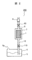
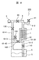
- FIG. 2 is a block diagram showing a schematic configuration of the coating apparatus according to the first embodiment.
- the coating device 200 according to the first aspect includes a tank 6 for storing the slurry 5, a housing 7 for storing the filter member 1, a pump 9 which is a decompression means capable of decompressing the inside of the housing 7, and a tank 6.
- the housing 7 and the pipes 8 and 10 and the valves 80 and 110 which are the communication means for communicating the decompression means (pump 9).
- the coating device 200 of the first aspect satisfies the condition that the gap L between the inner surface of the side wall portion of the housing 7 and the outer surface of the filter member 1 is equal to or less than the equivalent diameter d of the flow path of the filter member 1. It is configured to include.
- the components of the coating device 200 of the first aspect will be described in detail.
- Slurry 5 is a liquid for coating the filter member 1.
- the slurry 5 may be reused a predetermined number of times after coating one filter member 1.
- the tank 6 is a container for storing the slurry 5.
- the tank 6 is provided with an opening 6 g as an atmosphere introduction structure.
- the housing 7 has an internal space that houses the filter member 1 and is filled with the slurry 5.
- the internal space of the housing 7 may be simply abbreviated as "inside".
- the housing may be made of a transparent material whose inside can be visually recognized from the outside in whole or a part thereof. By providing a transparent region such as a transparent window with a transparent material, it is possible to check the coating status of the filter member and the discharge status of the slurry from the outside of the housing.
- the pump 9 which is a decompression means is a pump for removing air inside the housing 7 (in other words, depressurizing the internal space of the housing 7) in order to allow the slurry 5 to flow into the housing 7.
- the pump 9 may have an ability to send air into the housing 7 (in other words, pressurize the internal space of the housing 7) in order to promote the discharge of the slurry 5 temporarily filled in the housing 7.
- the pump 9 has an atmosphere introduction structure (not shown), and the inside of the housing 7 can be released to the atmosphere via a communication means.
- the direction of gravity is the direction from the top to the bottom of the paper surface in FIG.
- the housing 7, and the tank 6 are positioned from the top, so that the slurry 5 is moved from the housing 7.
- Gravity can be used when discharging.
- the present invention is not limited to this, and if the pump 9 has a pressurizing capacity, the above-mentioned hierarchical relationship may not be satisfied.
- the pipes 8 and 10 that are the communication means are components that connect the tank 6, the housing 7, and the pump 9 that is the decompression means.
- the tubes 8 and 10 may be rigid or elastic.
- the valves 80 and 110 are installed in the pipes 8 and 10, respectively, to form a communication means.
- pipes 8 and 10 and valves 80 and 110 which are communication means, are arranged as follows.
- a valve 110 is arranged in the pipe 10 that connects the tank 6 and the housing 7. Since the pipe 10 needs to extend into the liquid of the slurry 5, the end portion extends below the upper surface of the tank 6.
- a valve 80 is arranged in the pipe 8 that connects the housing 7 and the pump 9.
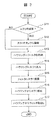
- FIG. 3 is a flowchart showing a processing flow of the coating method according to the first embodiment.
- the main body that performs each coating process is described as an operator, but some or all of the processes may be performed by a software program (or a computer that executes the program) (other embodiments described below). The same applies to).
- the gap L is A step of storing the filter member in a housing satisfying the condition of d or less is included.
- Step A The operator checks whether the slurry 5 is sufficiently contained in the tank 6 (S11), and if the amount of the slurry 5 is insufficient (YES in S11), the slurry 5 is used. It is supplied to the tank 6 (S12). If a sufficient amount of slurry 5 is already stored in the tank 6 (NO in S11), (S12) is unnecessary.
- Step B The operator stores the filter member 1 in the housing 7 that satisfies the above-mentioned gap L condition (S13). Note that (S12) and (S13) may be interchanged or may be performed at the same time.
- Step C The worker causes the slurry 5 to flow from the tank 6 to the housing 7 (S14).
- this process will be referred to as a "slurry inflow process”.
- Step D The operator waits until the filter member 1 housed in the housing 7 is sufficiently infiltrated with the slurry 5 (S15).
- the waiting time is considered to be, for example, about 5 minutes. If the housing 7 is provided with a transparent window or the like that allows the inside to be visually recognized from the outside, the operator monitors the filter member 1 from the transparent window or the like and performs this step at the timing when bubbles do not come out from the filter member 1. You may finish.
- Step E The worker discharges the slurry 5 from the housing 7 (S16).
- the discharged slurry 5 is returned to the tank 6.
- this step will be referred to as a "slurry discharge step".
- the valve 110 may be a three-way valve to branch the pipe 10 (not shown), and the slurry 5 may be discharged to a tank (not shown) different from the tank 6.
- Step F The worker takes out the filter member 1 from the housing 7 from which the slurry 5 is discharged (S17), and ends a series of steps.
- FIG. 4 is a flowchart showing details of the slurry inflow step in the coating method according to the first embodiment. Note that FIG. 4 also shows a flowchart showing details of the slurry inflow step in the coating method according to the second embodiment described later.
- the valve when the valve is described as "closed", it may include a state in which the flow of fluid in the pipe can be most restricted in terms of the function of the valve. In other words, even if some fluid leaks from the closed valve, it may be treated as "closed”.
- Step C11 The operator opens the valves 110 and 80 (S141).
- Step C12 The operator turns on the decompression operation of the pump 9 (S142). As a result, the inside of the housing 7 is depressurized, and the slurry 5 that has entered the tank 6 is sucked and flows into the housing 7 (S143). At that time, the water level of the slurry 5 in the tank 6 drops. As shown in FIG. 2, since the inside of the tank 6 is opened to the atmosphere by the opening 6 g, the gas deficient due to the water level drop inside the tank 6 can be replenished from the atmosphere, so that the suction of the slurry can be shortened in a short time. It can be carried out.
- Step C13 When the operator confirms that a sufficient amount of the slurry 5 is stored in the housing 7 (YES in S144), the decompression operation of the pump 9 is turned off (S145), and the slurry 5 is further housing. Prevent it from flowing into 7.
- step C11 it was assumed that the valve 110 was opened in (S141), but the timing for opening the valve 110 from the closed state was after the decompression operation of the pump 9 was turned on (S142) in step C12. You may.
- the slurry discharge step (S16) for discharging the slurry 5 stored in the housing 7 to the tank 6 and returning the slurry 5 is as follows.
- Step E11 The operator introduces the atmosphere into the housing 7 from the atmosphere introduction structure (not shown) of the pump 9 through the pipe 8 while keeping the valve 80 open. As a result, the pressure inside the housing 7 returns to atmospheric pressure.
- Step E12 The operator opens the valve 110.
- the slurry 5 contained in the housing 7 returns to the tank 6 by the action of atmospheric pressure and gravity. Since the gas that is no longer needed due to the rise in the water level of the slurry 5 inside the tank 6 is released to the atmosphere from the opening 6 g of the tank 6, the slurry can be discharged in a short time.
- the above is the details of the slurry discharge step (S16) of the first aspect.
- the side wall of the housing of aspect 1 is made of a rigid body.
- a housing having a rigid side wall may be referred to as a rigid side wall housing.
- the housing 7 shown in FIG. 2 illustrates the case of a rigid side wall housing.
- rigid body means that the housing or a member of the housing is not significantly deformed by the fluctuations of gravity, air pressure, and water pressure, which are the sources of the force applied to the housing. It does not mean that it does not deform at all.
- FIG. 5 is a perspective view showing the appearance of the rigid side wall housing, which is the housing of the coating device according to the first embodiment.
- the housing 7 of FIG. 5 has a lid 7-1, a side wall 7-2, and a bottom 7-3, and the side wall 7-2 is made of a rigid body.
- the dotted line in the figure indicates the back surface and the inner wall which cannot be seen from the viewpoint of the perspective view.
- the cushioning members 7-10 described later are exposed inside the housing 7, they are shown by solid lines for convenience of illustration.
- the housing 7 has a structure in which the lid 7-1 and the side wall 7-2 can be separated. Due to this structure, the upper portion of the side wall 7-2 of the housing 7 also serves as an entrance / exit port, so that the operator separates the lid 7-1 (opens the lid 7-1) and puts the filter member 1 into the housing 7. Can be stored in or retrieved from.
- the entrance / exit may be installed at another location.
- the lid 7-1 has an opening 7-4 for connecting to the pipe 8 shown in FIG. Since the housing 7 has an axially symmetrical shape, the opening 7-4 is preferably provided so as to include the geometric center of the lid 7-1.
- the bottom 7-3 has an opening 7-5 for connecting to the pipe 10 shown in FIG.
- the openings 7-5 are provided to include the geometric center of the base 7-3.
- the shape examples of the openings 7-4 and 7-5 are through holes having a circular cross section as shown in FIG. Further, as a part of the openings 7-4 and 7-5, a pipe for facilitating the connection with the pipes 8 and 10 may be provided outside the openings 7-4 and 7-5.
- the inner surfaces of the lid 7-1 and the bottom 7-3 do not have to be flat, and may be a funnel-shaped conical surface.
- the side wall 7-2 is fixed to the bottom 7-3 and is fixed in a separable state from the lid 7-1. Since the fixed portion between the side wall 7-2 and the lid 7-1 is required to be watertight and airtight, the contact portion between the side wall 7-2 and the lid 7-1 should have a fastening structure provided with a screw groove. Is preferable.
- O-rings 7-10T and 7-10B exemplified by O-rings are arranged on the lid 7-1 and the bottom 7-3 as cushioning members 7-10 having elastic force.
- the lid 7-1 and the bottom 7-3 are brought into contact with the filter member 1 via the elastic O-rings 7-10T and 7-10B. Therefore, the filter member 1 can be stably fixed inside the housing 7.
- the fact that there is a variation in the residual ratio of slurry in each flow path in the filter member means that the water treatment performance, which is the ability of the filter member, more specifically, the water treatment speed (the flow rate at which the filter member can treat water per unit time). ) And the removal rate of the predetermined component.
- the water treatment performance which is the ability of the filter member, more specifically, the water treatment speed (the flow rate at which the filter member can treat water per unit time).
- the removal rate of the predetermined component is because if the slurry remains in the flow path above the specified value and the coating is excessive, the flow path (particularly the partition wall made of porous ceramic) is clogged and the water treatment rate of the filter member is reduced. To do.
- the removal rate of the predetermined component decreases.
- the variation in the residual ratio of the slurry is large, for example, when trying to prioritize the removal of a predetermined component, it is necessary to retain more slurry based on the variation, that is, to sacrifice the water treatment rate by the variation. There is. In order to maximize both the water treatment rate, which is the water treatment performance of the filter member, and the removal ratio of the predetermined component, it is important to reduce the variation in the residual ratio of the slurry in the coating.
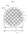
- FIG. 6 is a plan view showing a state in which the filter member is inserted into the rigid side wall housing shown in FIG.
- FIG. 6 is a view of the housing 7 in which the filter member 1 is inserted from above with the lid 7-1 shown in FIG. 5 removed, and the centers of the filter member 1 and the housing 7 coincide with each other.
- W is the inner diameter of the inner surface of the side wall portion of the housing 7 (hereinafter, may be referred to as “inner wall diameter” or “W”)
- R is the outer diameter of the outer surface of the filter member 1.
- L indicates a gap between the inner surface of the side wall portion of the housing 7 and the outer surface of the filter member 1 (hereinafter, may be simply referred to as “gap L”). Since the filter member 1 is inserted so that the center thereof coincides with the center of the housing 7, the gap L is half the difference between W and R (WR) / 2.
- the outer diameter R of the outer surface of the filter member 1 was set to 25.4 mm, and the length d of one side of the flow path 3 of the filter member was set to 2 mm.
- the filter member 1 was prepared.
- the filter member 1 was installed and stored in the center of the housing 7 and coated with a slurry by the coating device and the coating method of the mode 1, to prepare a plurality of filter members 1 under the condition that the dimensions of the gap L are different. The filter member once coated was not reused.
- the standard deviation was calculated by measuring the variation in the residual ratio of the slurry of the plurality of coated filter members.
- the residual ratio of the slurry is the volume (estimated from the weight) of the slurry remaining in the porous ceramic of the partition wall that partitions all the flow paths included in the filter member, and partitions all the flow paths included in the filter member. It is the ratio with the volume of the slurry that can be held in the porous ceramic of the partition wall as the denominator.
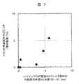
- FIG. 7 is a graph showing the relationship between the difference (WR) between the inner wall diameter W of the housing and the outer diameter R of the outer surface of the filter member and the variation in the residual ratio of the slurry.
- the horizontal axis represents the difference between W and R (WR)
- the vertical axis represents the variation in the residual ratio of the slurry as a standard deviation.
- the inventors of the present invention improved the slurry discharge property and the uniformity of the slurry discharge in the slurry discharge process to reduce the variation in the residual ratio of the slurry, and as a result, there was no outer skin.
- the gap L between the inner surface of the side wall portion of the housing and the outer surface of the filter member is defined by the following equation 1. However, it has been found that it is necessary to satisfy the condition that the equivalent diameter d or less of the flow path of the filter member is satisfied.
- the outer diameter R of the outer surface of the filter member and the filter The condition of the equivalent diameter d of the flow path of the member and the inner diameter W of the inner surface of the side wall portion of the housing is preferably that W is (R + 2d) or less.
- the inner wall diameter W of the housing is the outer diameter of the filter member.
- the outer diameter of the side surface must be R (25.4 mm) or more and R + 4 mm (29.4 mm) or less.
- the gap L between the inner surface of the side wall portion of the housing and the outer surface of the filter member must satisfy the condition that the equivalent diameter d or less of the flow path of the filter member is satisfied. ..
- the coating apparatus and coating method for the water treatment filter of the second embodiment (hereinafter, may be referred to as aspect 2), which is the embodiment according to the present invention, will be described with reference to the drawings.
- aspect 2 when the equivalent diameter of the flow path of the filter member is d and the gap between the inner surface of the side wall portion of the housing and the outer surface of the filter member is L, the gap L is d or less.
- the equivalent diameter of the flow path of the filter member is d and the gap between the inner surface of the side wall portion of the housing and the outer surface of the filter member is L, the gap L is d or less.
- FIG. 8 is a block diagram showing a schematic configuration of the coating apparatus according to the second embodiment.
- the coating device 200 of the second aspect is basically composed of a tank 6, a housing 7, and a pump 9 which is a decompression means, similarly to the coating device of the first aspect.
- the configurations of the communicating means for communicating the housing 7 and the depressurizing means (pump 9) are different. That is, in the coating device of the second aspect, a plurality of pipes and valves which are communication means are installed.
- the coating apparatus of aspect 2 is composed of tubes 8, 8-2, 10, 10-2, 10-3, 10-4 and valves 80, 81, 100, 110, 120, 130. ..
- the housing 7 is a rigid side wall housing, and the direction of gravity is the direction from the top to the bottom of the paper surface in FIG. 8, and the positional relationship between the pump 9, the housing 7, and the tank 6 is set from above. ..
- the components of the coating device 200 of the second aspect will be described in detail, but the same components as the coating device 200 of the first aspect are indicated by the same or similar reference numerals, and the description will be omitted without repeating in principle.
- the pipes 8, 8-2, 10, 10-2, 10-3, and 10-4 which are the means of communication, are components connecting the tank 6, the housing 7, and the pump 9, and are typically a plurality of components. Exists.
- the tubes 8, 8-2, 10, 10-2, 10-3, and 10-4 may be rigid bodies or elastic bodies.
- the valves 80, 81, 100, 110, 120 and 130 are installed in pipes 8, 8-2, 10, 10-2, 10-3 and 10-4, respectively, to form communication means.
- pipes 8, 8-2, 10, 10-2, 10-3, 10-4 and valves 80, 81, 100, 110, 120, 130, which are communication means, are arranged as follows. ing.
- valve 10-2 A valve 110 is arranged in the pipe 10-2 that connects the tank 6 and the housing 7. Since the pipe 10-2 needs to extend into the liquid of the slurry 5, the end portion extends below the upper surface of the tank 6.
- a valve 80 is arranged in the pipe 8 that connects the housing 7 and the pump 9.
- a valve 81 is arranged in the pipe 8-2 that branches from the pipe 8 (however, between the housing 7 and the valve 80) and is released to the atmosphere.
- valve 10-4 A valve 130 is arranged in the pipe 10-4 connecting the pump 9 and the tank 6. Since it is preferable that the pipe 10-4 does not extend into the liquid of the slurry 5, it is terminated at the upper surface of the tank 6.
- the valve 100 is arranged in the pipe 10 that branches from the pipe 10-4 (however, between the valve 130 and the tank 6) and is connected between the housing 7 of the pipe 10-2 and the valve 110. There is.
- a valve 120 is arranged in the pipe 10-3 that branches from the pipe 10 and is released to the atmosphere between the portion 10-40 where the pipe 10 branches from the pipe 10-4 and the valve 100. ing.
- the coating device 200 of the second aspect will be described. Assuming that the pipes 10-2 and 10-3 (below the branch source of the pipe 10) are arranged along the direction of gravity (vertical direction on the paper surface in FIG. 8; the same applies hereinafter), the coating method described later can be used. In the slurry discharging process of the above, the movement of the slurry by gravity is smooth, and the amount of the slurry remaining in the pipe 10 can be reduced.
- the branch point 10-20 with the pipe 10-2 is above the branch point 10-40 with the pipe 10-4 so as to follow the flow direction of the slurry 5. It is preferable that there is no or few parallel portions extending in the direction perpendicular to the direction of gravity, that is, in the left-right direction of the paper surface in FIG. With this configuration, the amount of slurry remaining in the pipe 10 can be reduced in the slurry discharge step in the coating method described later.
- the pump 9 does not necessarily have to be one.
- a pump that performs a decompression operation in the slurry inflow step and a pump that performs a decompression operation in the slurry discharge step may be configured as separate pumps.
- the valve 81 and the pipe 8-2 may be omitted, and the pump that was performing the decompression operation in the slurry inflow process may be switched to the pressurization operation, or the pump may be released to the atmosphere. Good.
- the coating method of the second aspect is basically the same as the coating method of the first aspect, and the coating process is carried out through the steps A to F according to the flowchart of FIG. 3 described above, but the details of the slurry inflow step and the slurry The details of the discharge process are different.
- the details of the slurry inflow process and the details of the slurry discharge process in the second aspect will be described with reference to the flowcharts of FIGS. 4, 9 and 10.
- FIG. 4 is a flowchart showing details of the slurry inflow step in the coating method according to the second embodiment.
- the slurry inflow step (S14) of the second aspect is as follows.
- Step C22 The operator turns on the decompression operation of the pump 9 (S142). As a result, the inside of the housing 7 is depressurized, and the slurry 5 that has entered the tank 6 is sucked and flows into the housing 7 (S143). At that time, the water level of the slurry 5 in the tank 6 drops. As shown in FIG. 8, a route leading to the tank 6 is secured from the pipe 10-3 released to the atmosphere via the valves 120 and the pipes 10 and 10-4 in the open state. As a result, since the inside of the tank 6 is released to the atmosphere, the gas deficient due to the water level drop inside the tank 6 can be replenished from the atmosphere, so that the slurry can be sucked in a short time.
- Step C23 When the operator confirms that a sufficient amount of the slurry 5 is stored in the housing 7 (YES in S144), the decompression operation of the pump 9 is turned off (S145), and the slurry 5 is further housing. Prevent it from flowing into 7.
- step C21 it was assumed that the valve 110 was opened in (S141), but the timing for opening the valve 110 from the closed state is after the decompression operation of the pump 9 is turned on (S142) in step C22. There may be.
- the slurry discharge step (S16) for discharging the slurry 5 stored in the housing 7 to the tank 6 and returning the slurry 5 is as follows.
- the slurry discharge step (S16) has two methods, a natural discharge step and a reduced pressure discharge step.
- the natural discharge process is a slurry discharge method that utilizes gravity when discharging the slurry 5 from the housing 7.
- the slurry discharge step in the details of the slurry discharge step of the first embodiment described above (step E11 and step E12) is a natural discharge step.
- the decompression discharge step is a slurry discharge method utilizing the decompression or pressurizing capacity of the pump 9, which is a decompression means, when the slurry 5 is discharged from the housing 7.
- a natural discharge step or a reduced pressure discharge step, or a method in which both are used in combination may be adopted.
- the reduced pressure discharge step may be performed after the natural discharge step, or the process may be performed in the reverse order.
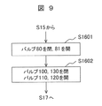
- FIG. 9 is a flowchart showing a natural discharge process among the details of the slurry discharge process in the coating method according to the second embodiment.
- the natural discharge step in the slurry discharge step (S16) of the second aspect is as follows.
- Step E21 The operator closes the valve 80 and opens the valve 81 (S1601). As a result, the atmosphere is introduced into the housing 7 from the pipe 8-2 released to the atmosphere, and the pressure inside the housing 7 returns to the atmospheric pressure.
- Step E22 The operator closes the valves 100 and 130 and opens the valves 110 and 120 (S1602).
- the slurry 5 contained in the housing 7 returns to the tank 6 by the action of atmospheric pressure and gravity.
- the gas that is no longer needed due to the rise in the water level of the slurry 5 inside the tank 6 is released to the atmosphere from the pipe 10-3 via a part of the pipe 10-4, a part of the pipe 10, and the valve 120.
- Slurry can be discharged naturally in a short time.
- the above is the natural discharge step in the slurry discharge step (S16) of the second aspect.
- FIG. 10 is a flowchart showing a decompression discharge step among the details of the slurry discharge step in the coating method according to the second embodiment.
- the decompression discharge step in the slurry discharge step (S16) of the second aspect is as follows.
- Step E201 The operator opens the valve 81 (S1611). As a result, the atmosphere is introduced into the housing 7 from the pipe 8-2 released to the atmosphere, and the pressure inside the housing 7 returns to the atmospheric pressure.
- Step E202 The operator closes the valves 80, 120, 110 and opens the valves 130, 100 (S1612).
- Step E203 The operator turns on the decompression operation of the pump 9 (S1613). As a result, the air pressure in the pipeline formed in step E202 is reduced, so that the slurry 5 remaining in the housing 7 is discharged. The slurry 5 falls into the tank 6 from the portion 10-40 where the pipe 10 branches from the pipe 10-4 due to the action of gravity. Further, the gas that is no longer needed due to the rise in the water level of the slurry 5 inside the tank 6 is sucked by the pump 9 through the pipe 10-4.
- the above is the decompression discharge step in the slurry discharge step (S16) of the second aspect.
- the coating apparatus and coating method for the water treatment filter of the third embodiment (hereinafter, may be referred to as aspect 3), which is the embodiment according to the present invention, will be described with reference to the drawings.
- the gap L is d or less.
- the housing of the third aspect is made of an elastic material at least a part of the inner side surface of the side wall portion thereof.
- a housing in which a part of the side wall portion is made of an elastic body may be referred to as an elastic side wall housing.
- the elastic side wall housing can solve the problem of both installation positions that the center of the filter member and the housing do not match.
- FIG. 11 is a perspective view showing the appearance of the elastic side wall housing of the housing of the coating device according to the third embodiment.
- FIG. 12 is a cross-sectional view showing a state in which the filter member is inserted into the elastic side wall housing shown in FIG.
- the housing 71 of the third aspect differs in that the side wall 7-2 of the housing 7 of the first aspect shown in FIG. 5 is a side wall 71-2f including an elastic body, and the other configurations are basically aspects. It is configured in the same manner as the housing 7 of 1.
- reference numeral 7 is replaced with reference numeral 71, and the description thereof will be omitted.
- the outer diameter of the side wall 71-2f and the outer diameter of the lid 71-1 may be substantially the same.
- the side wall 71-2f including the elastic body is composed of the elastic body part 71-2fe and the rigid body part 71-2fr.
- the side wall 71-2f may be composed of elastic parts 71-2fe as a whole.
- the rigid body part 71-2fr is preferably fixed to a lid 71-1 or a bottom 71-3 having a screw groove on the outside and a screw groove on the inside by screwing.
- the side wall 71-2f has a ring-shaped rubber-like elastic body 71-10T and 71-10B, a lid 71-1 and a bottom 71-3, and a rigid body part in order to improve watertightness and airtightness. It may be sandwiched between 71-2fr.
- the elastic body part 71-2fe is preferably flexible from the viewpoint of deformation performance described later, but is fixed when it is fixed by screw fastening or by ring-shaped rubber-like elastic bodies 71-10T and 71-10B. From the viewpoint of securing force, a rigid body is preferable. Further, since the side wall 71-2f is inferior in workability when the filter member 1 is taken in and out if it is broken by buckling, it is preferable that the side wall 71-2f is hard enough to stand on its own with the lid 71-1 removed. ..
- the length of the rigid body part 71-2fr is made longer than the length of the side wall of the lid 71-1 to finish closing the lid 71-1 to the side wall 71-2f ( Alternatively, it is preferable because a length that allows the operator to grip the side wall 71-2f can be secured at the time of starting to open.
- a fastening means other than screws may be used as long as the fixing force can be secured.
- a configuration or fixing method other than the ring-shaped rubber-like elastic bodies 71-10T and 71-10B may be used.
- the lid 71-1 and the side wall 71-2f have a structure that can be opened and closed.
- the equivalent diameter of the flow path of the filter member is set to d by the reduction of the gap due to the deformation of the elastic side wall housing, and the inner surface of the side wall portion of the housing and the outside of the filter member.
- the gap with the side surface is L
- the condition that the gap L is d or less can be satisfied.
- the elastic body parts (71-2fe) constituting the side wall (71-2f) including the elastic body of the elastic body side wall housing have sufficient deformation performance while having appropriate rigidity and hardness.
- the slurry is chemically resistant. Functions required as elastic parts such as deformation performance and chemical resistance can be obtained by appropriately selecting the material and its elastic force and thickness.
- a material suitable for elastic parts the amount of change in the thickness of the material after contact with the slurry at room temperature for one week or less is 1% or less, and the decrease in Young's modulus, which indicates the elastic modulus, is 5% or less. It is a material that is.
- materials having these characteristics include materials that combine one or more types from the composition group of fluororubber, and Kalrez (“Kalrez” is a registered trademark of DuPont), which is classified as a perfluoroelastomer of fluororubber. Conceivable.
- the material of the elastic body part may be a material having dilatancy characteristics.
- the dilatancy property is a property that is an elastic body while stress is applied and fluidly flows when the stress is removed.
- PU Polyurethane
- Polyurethane (PU) can be considered as a material having dilatancy characteristics and resistance to slurry.
- the elastic body part may be composed of a multi-layer structure made of a plurality of different materials.
- the surface of the inner surface of the elastic part that is in direct contact with the slurry has a layer of individual composition (for example, polyurethane), and the layer inside the polyurethane layer has a stronger dilatancy property, that is, liquid plastic (for example, polyurethane).
- the coating apparatus of the third embodiment (aspect 3) will be described. Since the coating device of the third aspect is basically configured in the same manner as the coating device of the first aspect or the second aspect, detailed description thereof will be omitted except for the preferable components in the coating device of the third aspect described below. ..
- a pressurizing means capable of pressurizing the inside of the housing.
- a pump as a pressurizing means capable of pressurizing the inside of the housing in the pipe 8-2.
- a pump capable of pressurizing the inside of the housing is installed, and after the slurry discharge step and before the step of taking out the filter member 1 from the housing 71, the pressurizing operation of the pump is turned on and the housing 71 When the inside is pressurized, the elastic body part 71-2fe is deformed outward and separated from the filter member 1, so that the filter member 1 can be easily taken out from the housing 71.
- the housing may have the functions of both the rigid side wall housing and the elastic side wall housing.
- the housing is configured by arranging a side wall 7-2 (shown in FIG. 5) made of a rigid body described in the first aspect on the outside of the side wall 71-2f including the elastic part 71-2fe. May be good.
- a side wall 7-2 shown in FIG. 5
- the side wall 7-2 made of a rigid body on the outside, it is possible to prevent the side wall 71-2f including the elastic body from being deformed to the outside when the housing is filled with slurry, and also supports the lid 71-1. be able to.
- the coating method of the third embodiment is basically the same as the coating method of the first aspect, and the coating process is carried out through the steps A to F according to the flowchart of FIG. 3 described above, but the elastic body side wall housing is inside.
- the slurry inflow process and the slurry discharge process are different in that they are deformed.
- the details of the slurry inflow step and the details of the slurry discharge step in the third aspect will be described only for the steps different from those of the first and second aspects, and the description of the same steps will be omitted.
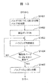
- FIG. 13 is a flowchart showing details of the slurry inflow step in the coating method according to the third embodiment.
- the elastic body part 71-2fe of the side wall 71-2f of the elastic side wall housing is deformed inward prior to the inflow of the slurry 5 into the housing 71. That is, in the slurry inflow step (S14) of the first aspect or the second aspect, the steps C31 to C33 described below are performed before the step C11 or the step C21, respectively.
- the valve that opens and closes in the slurry inflow step of aspect 3 differs due to the difference in the configuration of the coating device of aspect 1 and aspect 2, in the following description, the valve that opens and closes by the coating device of aspect 1 is described in [].
- the valve that opens and closes with the coating device of aspect 2 is shown outside [].
- the slurry inflow step (S14) of the third aspect is as follows.
- Step C31 The operator closes [Valve 110] and valves 100, 110, 130 and 81, and opens [Valve 80] and valve 80 (S1401).
- Step C32 The operator turns on the decompression operation of the pump 9 (S1402). As a result, the inside of the housing 7 is depressurized (S1403), and the elastic body part 71-2fe is deformed inward.
- Step C33 The operator checks the deformation of the elastic body part 71-2fe (S1404), and after confirming that the elastic body part 71-2fe is sufficiently deformed (YES in S1404), [Valve 110 ], The valves 110 and 120 are opened (S1405).
- the timing of changing the valve 120 from the closed state to the open state in (S1405) in step C33 is the elastic body part 71 in (S1404). It may be before confirming that -2fe is sufficiently deformed.
- the slurry discharge step (S16) of the third aspect basically discharges the slurry from the housing in the same step as the slurry discharge step of the first or second aspect, but is elastic among the above-mentioned natural discharge step and the reduced pressure discharge step. It is preferable to employ a reduced pressure discharge step in that the body side wall housing can be deformed inward. However, even in the case of the natural discharge process, if the slurry flow rate between the outer surface of the filter member and the inner surface of the elastic side wall housing is smaller than the flow rate of the flow path of the filter member, the natural discharge process is adopted. You may.
- the pump is before the step E201 in the decompression discharge step of the second aspect in which the valve 81 is opened and the pressure inside the housing 71 is set to the atmospheric pressure.
- the depressurization operation of 9 may be turned on to depressurize the inside of the housing 71.
- the filter member in a water treatment filter using a porous ceramic as a partition wall member, the filter member has a configuration in which the porous ceramic is exposed on the outer surface without being covered with the outer skin. Even if there is, it has become possible to reliably coat the porous ceramic of the partition member with the slurry. This makes it possible to use the water treatment filter without having an outer skin, and it has become possible to eliminate the problem of water pollution caused by the outer skin being deteriorated and peeled off.
Landscapes
- Engineering & Computer Science (AREA)
- Life Sciences & Earth Sciences (AREA)
- Chemical & Material Sciences (AREA)
- Wood Science & Technology (AREA)
- Ceramic Engineering (AREA)
- Coating Apparatus (AREA)
- Chemical Kinetics & Catalysis (AREA)
- Geology (AREA)
- Materials Engineering (AREA)
- Structural Engineering (AREA)
- Organic Chemistry (AREA)
- Mechanical Engineering (AREA)
- Filtering Materials (AREA)
- Application Of Or Painting With Fluid Materials (AREA)
Abstract
外皮による水質の汚染を発生させないよう外皮をなくした水処理フィルタにおいて、隔壁部材の多孔質セラミックにスラリを確実にコーティングするために、多孔質セラミックの隔壁で仕切られた複数の流路を有する円筒形状のフィルタ部材をスラリでコーティングするためのコーティング装置を、スラリを格納するタンクと、フィルタ部材を格納するハウジングであって、フィルタ部材の流路の等価直径をd、ハウジングの側壁部の内側面とフィルタ部材の外側面との隙間をLとした場合、隙間Lがd以下となる条件を満たすハウジングと、ハウジングの内部を減圧可能な減圧手段と、タンク、ハウジング及び前記減圧手段を連通する連通手段とを有して構成した。
Description
本発明は水処理フィルタをスラリでコーティングするコーティング装置及びコーティング方法に関する。
水処理フィルタは、主に多孔質材料、例えば多孔質セラミックで構成されるフィルタ部材を、スラリと呼ばれるコーティング剤でコーティングすることで製造される。フィルタ部材をスラリのコーティング剤でコーティングする方法として、例えば特許文献1には、セラミック一体性触媒担体部材の内部骨格構造をコーティング物質のスラリで含浸する方法が開示されている。
具体的には特許文献1の図1及び3ページ目右カラム乃至3ページ目左カラムに記載の通り、一体化物18の下部末端18aよりコーティングスラリを吸入するために、一体化物の上部末端18bにカバー14を被せ、カバー内を真空にすることでパン10のコーティングスラリを一体化物に吸い上げる、ことが開示されている。
特許文献1に開示された含浸方法によりスラリでコーティングするためには、一体化物の外側面が、多孔質ではないが含水性のあるセラミックの膜(以下、「外皮」と称する場合がある)で被覆されていることが前提である。外皮は含水すると、水の表面張力により水膜が形成されるため非通気性となり、外皮で覆われたフィルタ内部を真空に保つことができるからである。しかし、外皮のあるフィルタを水処理フィルタとして用いる場合には、コーティング後、実際に水処理に用いている間に、外皮は劣化し、水処理フィルタから剥離してしまう。その結果、処理後の水が外皮で汚れてしまう。当該傾向は水処理フィルタによる水処理時間が長くなるほど顕著となる。
本発明は、多孔質セラミックが外側面に露出しているフィルタ部材、即ち、外皮のないフィルタ部材であっても、隔壁部材の多孔質セラミックにスラリを確実にコーティングできる水処理フィルタのコーティング装置及びコーティング方法を提供することを目的とする。
上記した課題を解決するために、本発明では、多孔質セラミックの隔壁で仕切られた複数の流路を有するフィルタ部材をスラリでコーティングするための水処理フィルタのコーティング装置を、前記スラリを格納するタンクと、前記フィルタ部材を格納するハウジングであって、前記フィルタ部材の前記流路の等価直径をd、前記ハウジングの側壁部の内側面と前記フィルタ部材の外側面との隙間をLとした場合、前記隙間Lがd以下となる条件を満たす前記ハウジングと、前記ハウジングの内部を減圧可能な減圧手段と、前記タンク、前記ハウジング及び前記減圧手段を連通する連通手段とを有して構成した。
前記コーティング装置において、前記ハウジングは円筒形状としてもよい。前記ハウジングを円筒形状とした場合、前記フィルタ部材の外側面の外径をR、前記フィルタ部材の前記流路の等価直径をd、前記ハウジングの前記側壁部の前記内側面の内径をWとした場合、Wは(R+2d)以下であることが好ましい。また、前記コーティング装置において、前記ハウジングの前記側壁部は、前記内側面の少なくとも一部を弾性体素材により構成してもよい。
また、上記した課題を解決するために、本発明では、多孔質セラミックの隔壁で仕切られた複数の流路を有するフィルタ部材をスラリでコーティングする水処理フィルタのコーティング方法を、前記フィルタ部材の前記流路の等価直径をd、前記フィルタ部材を格納するハウジングの側壁部の内側面と前記フィルタ部材の外側面との隙間をLとした場合、前記隙間Lがd以下となる条件を満たす前記ハウジングに前記フィルタ部材を格納し、減圧手段により前記ハウジングの内部を減圧することにより、前記ハウジングと連通するタンクに格納されたスラリを前記ハウジングの内部に吸引して流入させ、前記スラリを前記フィルタ部材に浸潤させた後、前記ハウジングから前記スラリを排出させるようにした。
前記コーティング方法において、前記ハウジングは円筒形状として、円筒形状の前記フィルタ部材を前記スラリでコーティングしてもよい。前記ハウジングを円筒形状とした場合、前記フィルタ部材の外側面の外径をR、前記フィルタ部材の前記流路の等価直径をd、前記ハウジングの前記側壁部の前記内側面の内径をWとした場合、Wは(R+2d)以下であることが好ましい。
前記コーティング方法において、前記スラリを前記ハウジングの内部に吸引して流入させることを、前記タンクの内部を大気に解放した状態で行ってもよい。また、前記スラリを前記ハウジングの内部に吸引して流入させることを、前記減圧手段により前記ハウジングの内部を減圧して前記ハウジングの前記側壁部を内側に変形させた後に行ってもよい。
前記コーティング方法において、前記ハウジングから前記スラリを排出させることを、前記減圧手段により前記ハウジングの内部を減圧して前記ハウジングの前記側壁部を内側に変形させた後に行ってもよい。
本発明によれば、外皮のないフィルタ部材であっても、隔壁部材の多孔質セラミックにスラリを確実にコーティングできるので、外皮のない水処理フィルタが得られ、以って外皮が劣化して剥がれ落ちることによる水質汚染の問題を解決できる。
(第1実施形態)
以下、本発明に係る好ましい実施の形態である第1実施形態(以下、態様1と称する場合がある。)の水処理フィルタのコーティング装置及びコーティング方法について、図面を参照して説明する。
以下、本発明に係る好ましい実施の形態である第1実施形態(以下、態様1と称する場合がある。)の水処理フィルタのコーティング装置及びコーティング方法について、図面を参照して説明する。
<第1実施形態のフィルタ部材>
まず、本発明においてコーティング対象となる外皮の無いフィルタ部材について説明する。図1は、第1実施形態に係るフィルタ部材1の形状を示した図で、(a)は平面図、(b)は正面の断面図である。フィルタ部材1の端面および側壁は、外皮の無い構造のため、多孔質セラミックの材質が露出している。態様1のフィルタ部材1は、円筒形状であって、外径Rの円筒状の外側面を有し、さらに多孔質セラミックの隔壁2で仕切られた、複数の流路3(より具体的には流路3a及び流路3b)とを有している。なお、本発明においてコーティング対象のフィルタ部材は、円筒形状に限定されず、流路の延伸方向に対して直行方向の断面視で、楕円形、三角形、正方形、長方形、多角形など円形以外の形状であってもよい。
まず、本発明においてコーティング対象となる外皮の無いフィルタ部材について説明する。図1は、第1実施形態に係るフィルタ部材1の形状を示した図で、(a)は平面図、(b)は正面の断面図である。フィルタ部材1の端面および側壁は、外皮の無い構造のため、多孔質セラミックの材質が露出している。態様1のフィルタ部材1は、円筒形状であって、外径Rの円筒状の外側面を有し、さらに多孔質セラミックの隔壁2で仕切られた、複数の流路3(より具体的には流路3a及び流路3b)とを有している。なお、本発明においてコーティング対象のフィルタ部材は、円筒形状に限定されず、流路の延伸方向に対して直行方向の断面視で、楕円形、三角形、正方形、長方形、多角形など円形以外の形状であってもよい。
複数の流路3は、図1(a)の平面図で見た場合に、端面において互いに平行でない第1方向および第2方向に並んで配置されており、図1(b)の正面の断面図で見た場合に、流入側の端面または流出側の端面の何れか一方に交互に設けられた封止部4とを有する。
なお、封止部4は、水及び洗浄液を透過させない素材であることが好ましい。さらに、水及び洗浄液に長時間接した場合に劣化や溶出が少ないことが好ましい。素材の例としては、セラミック、シーリング剤(シリコーン、エポキシ、アクリル系)、接着剤、コーキング剤がある。
流路3は、処理前の水の流入側(図1(b)における下)が開口し、反対側の処理後の水の流出側が封止部4によって封止された第1の流路3bと、処理後の水の流出側(図1(b)における上)が開口し、反対側の処理前の水の流入側が封止部4によって封止された第2の流路3aとの2種類がある。第1の流路と第2の流路とは、第1方向および第2方向にそれぞれ交互に配置されている。
ここで、流路3の等価直径dをd=4S/V、ここでSは流路断面積、Vは濡れ縁長さで流路の辺の合計長、と定義する。図1のように流路3が正方形の場合は、dは一辺の長さに当たる。
なお、多孔質セラミックの材質は、コーディエライト、アルミナ、シリカ、マグネシア、チタニアなどが考えられるが、多孔質のフィルタが形成できれば上記に限定されるものではない。しかし、多孔質セラミックの材質は、熱膨張率が小さいため成形が容易なコーディエライト、アルミナが好ましい。
<第1実施形態のコーティング装置>
以下、第1実施形態(態様1)のコーティング装置について説明する。図2は、第1実施形態に係るコーティング装置の概略の構成を示したブロック図である。図2に示すように、態様1のコーティング装置200は、スラリ5を格納するタンク6、フィルタ部材1を格納するハウジング7、ハウジング7の内部を減圧可能な減圧手段であるポンプ9、並びにタンク6、ハウジング7及び減圧手段(ポンプ9)を連通する連通手段である管8、10及びバルブ80、110より構成される。そして、態様1のコーティング装置200は、ハウジング7の側壁部の内側面とフィルタ部材1の外側面との隙間Lが、フィルタ部材1の流路の等価直径d以下となる条件を満たすハウジング7を含んで構成されている。以下、態様1のコーティング装置200の構成要素について詳しく説明する。
以下、第1実施形態(態様1)のコーティング装置について説明する。図2は、第1実施形態に係るコーティング装置の概略の構成を示したブロック図である。図2に示すように、態様1のコーティング装置200は、スラリ5を格納するタンク6、フィルタ部材1を格納するハウジング7、ハウジング7の内部を減圧可能な減圧手段であるポンプ9、並びにタンク6、ハウジング7及び減圧手段(ポンプ9)を連通する連通手段である管8、10及びバルブ80、110より構成される。そして、態様1のコーティング装置200は、ハウジング7の側壁部の内側面とフィルタ部材1の外側面との隙間Lが、フィルタ部材1の流路の等価直径d以下となる条件を満たすハウジング7を含んで構成されている。以下、態様1のコーティング装置200の構成要素について詳しく説明する。
スラリ5は、フィルタ部材1をコーティングするための液体である。スラリ5は一つのフィルタ部材1をコーティングした後に、所定回数、再利用してもよい。
タンク6は、スラリ5を格納する容器である。タンク6には大気導入構造として開口6gが設けられている。
ハウジング7は、フィルタ部材1を格納し、かつスラリ5で満たされる、内部空間を有する。なお、以下、ハウジング7の内部空間を単に「内部」と省略することがある。ハウジングは、その全体又は一部を、外部から内部を視認可能な透過性素材から構成してもよい。透過性素材により透明窓等の透過領域を設けることで、フィルタ部材のコーティング状況やスラリの排出状況をハウジングの外部から確認することができる。
減圧手段であるポンプ9は、スラリ5をハウジング7に流入させるために、ハウジング7内部の空気を除去(言い換えれば、ハウジング7の内部空間を減圧)するためのポンプである。なお、ポンプ9はハウジング7に一時満たされたスラリ5の排出を促進するために、ハウジング7内部に空気を送り込む(言い換えれば、ハウジング7の内部空間を加圧する)能力を有してもよい。また、ポンプ9は、不図示の大気導入構造を有し、連通手段を介してハウジング7内部を大気に解放可能としている。なお、態様1のコーティング装置200において、重力方向は図2で紙面の上から下に向かう方向として、上からポンプ9、ハウジング7、タンク6の位置関係とすることで、スラリ5をハウジング7から排出する際に重力を利用可能としている。しかし、これに限定されず、ポンプ9に加圧能力がある場合は前述の上下関係を満たさなくてもよい。
連通手段である管8、10は、前述のタンク6、ハウジング7、及び減圧手段であるポンプ9を接続する構成要素である。なお、管8、10は剛体でもよく、弾性体でもよい。バルブ80、110は、夫々、管8、10に設置されて連通手段を構成する。
図2に示すように、連通手段である管8、10及びバルブ80、110は以下の通り配置されている。
(管10)タンク6と、ハウジング7との間を接続する管10は、バルブ110が配置されている。なお、管10は、スラリ5の液体中まで伸びている必要があるため、端部はタンク6上面より下にまで伸びている。
(管8)ハウジング7と、ポンプ9との間を接続する管8は、バルブ80が配置されている。
<第1実施形態のコーティング方法>
以下、第1実施形態(態様1)のコーティング方法について説明する。図3は、第1実施形態に係るコーティング方法の処理の流れを示すフローチャートである。なお、コーティングの各工程を行う主体は、作業者として説明するが、一部又は全ての工程をソフトウェアプログラム(或いは当該プログラムを実行する計算機)で行ってもよい(以下、説明する他の実施形態についても同様である)。そして、態様1のコーティング方法は、フィルタ部材の流路の等価直径をd、フィルタ部材を格納するハウジングの側壁部の内側面とフィルタ部材の外側面との隙間をLとした場合、隙間Lがd以下となる条件を満たすハウジングにフィルタ部材を格納する工程を含んでいる。以下、図3のフローチャートに従って各工程(工程A~F)を説明する。
以下、第1実施形態(態様1)のコーティング方法について説明する。図3は、第1実施形態に係るコーティング方法の処理の流れを示すフローチャートである。なお、コーティングの各工程を行う主体は、作業者として説明するが、一部又は全ての工程をソフトウェアプログラム(或いは当該プログラムを実行する計算機)で行ってもよい(以下、説明する他の実施形態についても同様である)。そして、態様1のコーティング方法は、フィルタ部材の流路の等価直径をd、フィルタ部材を格納するハウジングの側壁部の内側面とフィルタ部材の外側面との隙間をLとした場合、隙間Lがd以下となる条件を満たすハウジングにフィルタ部材を格納する工程を含んでいる。以下、図3のフローチャートに従って各工程(工程A~F)を説明する。
(工程A)作業者は、タンク6の内部にスラリ5が十分入っているかをチェックし(S11)、スラリ5の量が不足している場合(S11でYESの場合)には、スラリ5をタンク6に供給する(S12)。なお、既にタンク6に十分な量のスラリ5が格納されている場合(S11でNOの場合)は、(S12)は不要である。
(工程B)作業者は、前述した隙間Lの条件を満たすハウジング7にフィルタ部材1を格納する(S13)。なお、(S12)と(S13)とは入れ替えてもよく、同時に行ってもよい。
(工程C)作業者は、タンク6からハウジング7に、スラリ5を流入させる(S14)。以下の説明では本工程を「スラリ流入工程」と称する。
(工程D)作業者は、ハウジング7に格納されたフィルタ部材1にスラリ5を十分浸潤させるまで待つ(S15)。なお、当該待ち時間は例えば5分程度と考えられる。なお、ハウジング7に外部から内部を視認可能な透明窓等を設けていれば、作業者は、透明窓等からフィルタ部材1を監視し、フィルタ部材1から泡沫が出なくなったタイミングで本工程を終えてもよい。
(工程E)作業者は、ハウジング7からスラリ5を排出させる(S16)。排出させたスラリ5はタンク6に戻される。以下の説明では、本工程を「スラリ排出工程」と称する。本態様では、排出させたスラリ5はタンク6に戻される形態について説明したが、そうでなくてもよい。例えば、バルブ110を三方弁にして管10を枝分かれさせ(図示せず)、スラリ5をタンク6とは別のタンク(図示せず)に排出してもよい。
(工程F)作業者は、スラリ5を排出させたハウジング7からフィルタ部材1を取り出して(S17)、一連の工程を終了する。
<<第1実施形態のスラリ流入工程の詳細>>
図4は、第1実施形態に係るコーティング方法におけるスラリ流入工程の詳細を示すフローチャートである。なお、図4は後述する第2実施形態に係るコーティング方法におけるスラリ流入工程の詳細を示すフローチャートも併記している。なお、以下の説明で、バルブが「閉じる」と表記した場合は、バルブの機能上で最も管内の流体の流れを制限できる状態を含んでもよい。言い換えれば、閉状態にしたバルブから多少の流体が漏れたとしても、「閉」として扱ってもよい。また、以下の説明で、バルブを「閉状態とする」と表記した場合は、バルブが開状態である場合は閉じる操作を行い、元々閉状態である場合はそのまま閉状態で維持することを指す。「開状態にする」も「開/閉」が逆な以外は同様の意味である(以下、説明する他の実施形態についても同様である)。態様1のスラリ流入工程(S14)は、下記の通りである。
図4は、第1実施形態に係るコーティング方法におけるスラリ流入工程の詳細を示すフローチャートである。なお、図4は後述する第2実施形態に係るコーティング方法におけるスラリ流入工程の詳細を示すフローチャートも併記している。なお、以下の説明で、バルブが「閉じる」と表記した場合は、バルブの機能上で最も管内の流体の流れを制限できる状態を含んでもよい。言い換えれば、閉状態にしたバルブから多少の流体が漏れたとしても、「閉」として扱ってもよい。また、以下の説明で、バルブを「閉状態とする」と表記した場合は、バルブが開状態である場合は閉じる操作を行い、元々閉状態である場合はそのまま閉状態で維持することを指す。「開状態にする」も「開/閉」が逆な以外は同様の意味である(以下、説明する他の実施形態についても同様である)。態様1のスラリ流入工程(S14)は、下記の通りである。
(工程C11)作業者は、バルブ110、80を開状態とする(S141)。
(工程C12)作業者は、ポンプ9の減圧動作をオンにする(S142)。これにより、ハウジング7の内部が減圧されて、タンク6に入ったスラリ5が吸引され、ハウジング7に流入する(S143)。その際、タンク6のスラリ5の水位は下がる。図2に示すように、タンク6は、開口6gによりその内部を大気に解放しているので、タンク6の内部における水位降下によって不足する気体を大気から補充できるので、スラリの吸引を短時間に行うことができる。
(工程C13)作業者は、ハウジング7にスラリ5が十分な量格納されたことを確認したら(S144でYESの場合)、ポンプ9の減圧動作をオフにし(S145)、これ以上スラリ5をハウジング7に流入させないようにする。
以上が態様1のスラリ流入工程(S14)の詳細である。なお、工程C11において、(S141)でバルブ110を開状態とするとしたが、バルブ110を閉状態から開状態とするタイミングは工程C12においてポンプ9の減圧動作をオン(S142)にした後であってもよい。
<<第1実施形態のスラリ排出工程の詳細>>
第1実施形態(態様1)に係るコーティング方法において、ハウジング7に格納されたスラリ5をタンク6に排出して戻すスラリ排出工程(S16)は、下記の通りである。
第1実施形態(態様1)に係るコーティング方法において、ハウジング7に格納されたスラリ5をタンク6に排出して戻すスラリ排出工程(S16)は、下記の通りである。
(工程E11)作業者は、バルブ80を開状態のまま、ポンプ9の不図示の大気導入構造から管8を介してハウジング7に大気を導入する。これによりハウジング7内部の気圧は大気圧に戻る。
(工程E12)作業者は、バルブ110を開状態とする。これにより、ハウジング7に入っていたスラリ5が大気圧と重力の働きによりタンク6に戻る。なお、タンク6内部のスラリ5の水位上昇によって不要となった気体は、タンク6の開口6gから大気に解放されることから、スラリの排出を短時間に行うことができる。以上が態様1のスラリ排出工程(S16)の詳細である。
<第1実施形態のハウジング(剛体側壁ハウジング)>
以下、第1実施形態のコーティング装置におけるハウジングの構成について説明する。態様1のハウジングは、その側壁部が剛体からなる。なお、以下の説明では側壁部が剛体のハウジングを剛体側壁ハウジングと称する場合がある。図2に示すハウジング7は剛体側壁ハウジングの場合を例示している。
以下、第1実施形態のコーティング装置におけるハウジングの構成について説明する。態様1のハウジングは、その側壁部が剛体からなる。なお、以下の説明では側壁部が剛体のハウジングを剛体側壁ハウジングと称する場合がある。図2に示すハウジング7は剛体側壁ハウジングの場合を例示している。
なお、ここで言う「剛体」とは、ハウジングに対して与えられる力の源となる、重力、空気圧の変動、水圧の変動によって、ハウジング又はハウジングの部材が大幅に変形しない物体であることを意味しており、まったく変形しないことを意味するものではない。
図5は、第1実施形態に係るコーティング装置のハウジングであって剛体側壁ハウジングの外観を示した斜視図である。なお、説明を簡単にするため、コーティング対象のフィルタ部材が円筒形状であって、フィルタ部材の外側面とハウジングの側壁部の内側面とが共に円筒である場合について説明する。図5のハウジング7は、蓋7-1と、側壁7-2と、底7-3とを有し、側壁7-2は剛体により構成されている。なお、図中の点線は、斜視図の視点から見えない背面や内壁を示している。また、後述する緩衝部材7-10は、ハウジング7の内部に露出しているが、図示の都合により実線で記載している。
ハウジング7は、蓋7-1と側壁7-2とが分離可能な構造となっている。この構造により、ハウジング7の側壁7-2の上部が出し入れ口の役割を兼ねているので、作業者は蓋7-1を分離させ(蓋7-1を開けて)、フィルタ部材1をハウジング7に格納する、或いは取り出すことができる。なお、出し入れ口は他の箇所に設置されてもよい。
蓋7-1は、図2に示す管8と接続するための開口部7-4を有する。ハウジング7は軸対象の形状を有するため、開口部7-4は、蓋7-1の幾何学的中心を含むように設けられていることが好ましい。
底7-3は、図2に示す管10と接続するため開口部7-5を有する。開口部7-5は、底7-3の幾何学的中心を含むように設けられている。なお、開口部7-4及び開口部7-5の形状例は、図5に示すような断面が円の貫通穴である。また、開口部7-4及び7-5の一部として、管8及び10との接続を容易にする管を開口部7-4及び7-5の外部に設けてもよい。なお、蓋7-1及び底7-3の内面は平面でなくてもよく、漏斗状の円錐面であってもよい。
側壁7-2は、底7-3と固定されており、蓋7-1とは分離可能な状態で固定されている。なお、側壁7-2と蓋7-1との固定部分の水密性や気密性が求められるため、側壁7-2と蓋7-1との接触部分はネジ溝を設けた締結構造とすることが好ましい。
なお、蓋7-1及び底7-3には、弾性力を有する緩衝部材7-10として、Oリングで例示されるOリング7-10T、7-10Bが配置されていることが好ましい。ネジ締結により蓋7-1を回転させて閉めることで、弾性力を有するOリング7-10T、7-10Bを介して、蓋7-1及び底7-3とフィルタ部材1とを当接せしめることから、フィルタ部材1をハウジング7の内部に安定的に固定することができる。
<スラリの残留割合とフィルタの水処理性能との関係>
ここで、コーティング後にフィルタ部材に残留するスラリの残留割合とフィルタとしての水処理性能との関係について説明する。フィルタ部材にスラリを確実にコーティングするためには、各流路の隔壁部材の多孔質セラミックに過不足なくスラリをコーティングすることが重要となる。このためには、スラリをフィルタ部材に浸潤させた後のスラリ排出工程でのスラリの排出性及びスラリ排出の均一性を向上させて、フィルタ部材の各流路に残留するスラリの量を適切に制御しなければならない。各流路に残留するスラリ量の適否はスラリの残留割合のばらつきとして評価される。
ここで、コーティング後にフィルタ部材に残留するスラリの残留割合とフィルタとしての水処理性能との関係について説明する。フィルタ部材にスラリを確実にコーティングするためには、各流路の隔壁部材の多孔質セラミックに過不足なくスラリをコーティングすることが重要となる。このためには、スラリをフィルタ部材に浸潤させた後のスラリ排出工程でのスラリの排出性及びスラリ排出の均一性を向上させて、フィルタ部材の各流路に残留するスラリの量を適切に制御しなければならない。各流路に残留するスラリ量の適否はスラリの残留割合のばらつきとして評価される。
フィルタ部材にて各流路のスラリの残留割合のばらつきがあるということは、フィルタ部材の能力である水処理性能、より具体的には水処理速度(単位時間当たりにフィルタ部材が水処理できる流量である)と所定成分の除去割合とに影響を及ぼす。なぜならば、流路にスラリが規定値以上に残留して、コーティングが過剰な場合は、流路(特に多孔質セラミックで構成される隔壁)が目詰まりをおこし、フィルタ部材の水処理速度が低下する。反対に、流路に残留するスラリが規定値以下であって、コーティングが不足する場合は所定成分の除去割合が低下する。
スラリの残留割合のばらつきが大きいと、例えば、所定成分の除去を優先しようとする場合には、ばらつきを踏まえてより多くのスラリを残留させる、つまり水処理速度をばらつきの分だけ犠牲にする必要がある。フィルタ部材の水処理性能である水処理速度と所定成分の除去割合の両者を最大化するには、コーティングにおけるスラリの残留割合のばらつきを低減することが重要である。
<ハウジングの側壁部の内側面とフィルタ部材の外側面との隙間とスラリの残留割合のばらつきとの関係>
本発明の発明者らは、スラリ排出工程でのスラリの排出性及びスラリ排出の均一性を向上してスラリの残留割合のばらつきを低減するためには、スラリ排出工程でフィルタ部材の各流路に適切に気圧を作用させる必要があることに着目した。スラリ排出工程で各流路に作用する気圧は、外皮のないフィルタ部材では、ハウジングの側壁部の内側面とフィルタ部材の外側面との隙間の寸法の影響を受けると推察された。そこで、ハウジングの側壁部の内側面とフィルタ部材の外側面との隙間の寸法を変化させたときのスラリの残留割合のばらつきについて調査した。
本発明の発明者らは、スラリ排出工程でのスラリの排出性及びスラリ排出の均一性を向上してスラリの残留割合のばらつきを低減するためには、スラリ排出工程でフィルタ部材の各流路に適切に気圧を作用させる必要があることに着目した。スラリ排出工程で各流路に作用する気圧は、外皮のないフィルタ部材では、ハウジングの側壁部の内側面とフィルタ部材の外側面との隙間の寸法の影響を受けると推察された。そこで、ハウジングの側壁部の内側面とフィルタ部材の外側面との隙間の寸法を変化させたときのスラリの残留割合のばらつきについて調査した。
以下、前述の隙間の寸法とスラリの残留割合のばらつきとの関係の調査結果について述べる。図6は、図5に示す剛体側壁ハウジングにフィルタ部材を挿入した状態を示す平面図である。図6は、フィルタ部材1が入れられた状態のハウジング7を、図5に示す蓋7-1を外した状態で上から見た図であって、フィルタ部材1とハウジング7との中心を一致させてフィルタ部材1をハウジング7に設置した場合を示している。図6で、Wはハウジング7の側壁部の内側面の内径(以下、「内壁径」と称する場合や、「W」と称する場合がある)を、Rはフィルタ部材1の外側面の外径を示している。また、図6で、Lはハウジング7の側壁部の内側面とフィルタ部材1の外側面との隙間(以下、単に「隙間L」と称する場合がある)を示している。フィルタ部材1は、その中心をハウジング7の中心と一致させて挿入しているので、隙間Lは、WとRとの差の半分である(W-R)/2となる。隙間Lの寸法とスラリの残留割合のばらつきとの関係を調査するため、フィルタ部材1の外側面の外径Rを25.4mm、フィルタ部材の流路3の一辺の長さdを2mmとしたフィルタ部材1を準備した。一方、ハウジング7の側壁部の内側面にテープを貼り付けて、疑似的にハウジング7の内壁径Wを変化させることで、(W-R)の値、即ち、隙間L((W-R)/2で求まる値)の寸法を変化させた。フィルタ部材1をハウジング7の中心に設置して格納して、様態1のコーティング装置及びコーティング方法によりスラリでコーティングして、隙間Lの寸法が異なる条件での複数のフィルタ部材1を作製した。なお、一度コーティングしたフィルタ部材は再利用しなかった。
コーティングした複数のフィルタ部材のスラリの残留割合のばらつきを測定してその標準偏差を算出した。なお、スラリの残留割合とは、フィルタ部材が含む全ての流路を仕切る隔壁の多孔質セラミック内に残留したスラリの体積(重量から推定)を分子に、フィルタ部材が含む全ての流路を仕切る隔壁の多孔質セラミック内に保持することのできるスラリの体積を分母とした割合である。図7は、ハウジングの内壁径Wとフィルタ部材の外側面の外径Rとの差(W-R)と、スラリの残留割合のばらつきとの関係を示すグラフである。図7で、横軸はWとRとの差(W-R)を、縦軸はスラリの残留割合のばらつきを標準偏差で示した。
図7に示す通り、WとRとの差(W-R)が4mmを超えると、即ち、フィルタ部材の流路の一辺の長さd(2mm)の2倍を超えると、スラリの残留割合のばらつきが急激に大きくなることがわかる。本調査ではフィルタ部材とハウジングとの中心を一致させていることから、隙間Lの寸法((W-R)/2)が、フィルタ部材の流路の一辺の長さdを超えると、スラリの残留割合のばらつきが急激に大きくなる、と言い換えることができる。
<フィルタ部材とハウジングの中心が一致する場合>
上述の調査結果から、本発明の発明者らは、スラリ排出工程でのスラリの排出性及びスラリ排出の均一性を向上してスラリの残留割合のばらつきを低減して、結果として、外皮のない多孔質セラミックが外側面に露出しているフィルタ部材にスラリを確実にコーティングするためには、以下の数1で定めるように、ハウジングの側壁部の内側面とフィルタ部材の外側面との隙間Lが、フィルタ部材の流路の等価直径d以下となる条件を満たす必要があることを見出した。また、フィルタ部材とハウジングとが共に円筒形状であって、フィルタ部材をハウジングに設置する際に、フィルタ部材とハウジングとの中心が一致する場合には、フィルタ部材の外側面の外径R、フィルタ部材の流路の等価直径d及びハウジングの側壁部の内側面の内径Wの条件は、Wが(R+2d)以下であることが好ましい。具体的には、上述の調査で例示した、外側面の外径Rが25.4mm、流路の一辺が2mmのフィルタ部材をコーティングする場合には、ハウジングの内壁径Wは、フィルタ部材の外側面の外径R(25.4mm)以上、R+4mm(29.4mm)以下とする必要がある。
上述の調査結果から、本発明の発明者らは、スラリ排出工程でのスラリの排出性及びスラリ排出の均一性を向上してスラリの残留割合のばらつきを低減して、結果として、外皮のない多孔質セラミックが外側面に露出しているフィルタ部材にスラリを確実にコーティングするためには、以下の数1で定めるように、ハウジングの側壁部の内側面とフィルタ部材の外側面との隙間Lが、フィルタ部材の流路の等価直径d以下となる条件を満たす必要があることを見出した。また、フィルタ部材とハウジングとが共に円筒形状であって、フィルタ部材をハウジングに設置する際に、フィルタ部材とハウジングとの中心が一致する場合には、フィルタ部材の外側面の外径R、フィルタ部材の流路の等価直径d及びハウジングの側壁部の内側面の内径Wの条件は、Wが(R+2d)以下であることが好ましい。具体的には、上述の調査で例示した、外側面の外径Rが25.4mm、流路の一辺が2mmのフィルタ部材をコーティングする場合には、ハウジングの内壁径Wは、フィルタ部材の外側面の外径R(25.4mm)以上、R+4mm(29.4mm)以下とする必要がある。

<フィルタ部材とハウジングの中心が一致しない場合>
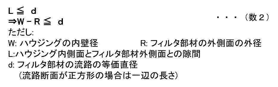
コーティング処理において、作業者がフィルタ部材をハウジングに格納する際に、ミリメートル単位の正確さで、フィルタ部材をハウジング内部の中心に設置することは困難を伴う。また、スラリ流入工程及びスラリ排出工程において、フィルタ部材がハウジングの内部で移動する可能性もある。最も極端な状態としては、フィルタ部材の外側面がハウジングの側壁部の内側面に接触する場合が想定される。即ち、フィルタ部材とハウジングの中心が一致しない場合には、隙間Lは、WとRとの差の半分である(W-R)/2とはならず、WとRとの差(W-R)で決定されることから、数1の条件は数2の条件に変形される。フィルタ部材とハウジングの中心が一致しない場合にも、ハウジングの側壁部の内側面とフィルタ部材の外側面との隙間Lは、フィルタ部材の流路の等価直径d以下となる条件を満たす必要がある。
(第2実施形態)
以下、本発明に係る実施の形態である第2実施形態(以下、態様2と称する場合がある。)の水処理フィルタのコーティング装置及びコーティング方法について、図面を参照して説明する。態様2のコーティング装置及びコーティング方法においても、フィルタ部材の流路の等価直径をd、ハウジングの側壁部の内側面とフィルタ部材の外側面との隙間をLとした場合、隙間Lがd以下となる条件を満たす構成又は工程を含んでいる。なお、コーティング対象となるフィルタ部材については、第1実施形態と同様なので説明を省略する。
<第2実施形態のコーティング装置>
以下、第2実施形態(態様2)のコーティング装置について説明する。図8は、第2実施形態に係るコーティング装置の概略の構成を示したブロック図である。図8に示すように、態様2のコーティング装置200は、基本的には態様1のコーティング装置と同様に、タンク6、ハウジング7、減圧手段であるポンプ9より構成されているが、タンク6、ハウジング7及び減圧手段(ポンプ9)を連通する連通手段の構成が相違している。即ち、態様2のコーティング装置では、連通手段である管及びバルブが複数設置されている。具体的には、態様2のコーティング装置は、管8、8-2、10、10-2、10-3、10-4及びバルブ80、81、100、110、120、130により構成されている。なお、態様2のコーティング装置200において、ハウジング7は剛体側壁ハウジングであり、重力方向は図8で紙面の上から下に向かう方向として、上からポンプ9、ハウジング7、タンク6の位置関係としている。以下、態様2のコーティング装置200の構成要素について詳しく説明するが、態様1のコーティング装置200と同様の構成要素は同一又は類似の符号で示し、説明は原則として繰り返さず省略する。
以下、第2実施形態(態様2)のコーティング装置について説明する。図8は、第2実施形態に係るコーティング装置の概略の構成を示したブロック図である。図8に示すように、態様2のコーティング装置200は、基本的には態様1のコーティング装置と同様に、タンク6、ハウジング7、減圧手段であるポンプ9より構成されているが、タンク6、ハウジング7及び減圧手段(ポンプ9)を連通する連通手段の構成が相違している。即ち、態様2のコーティング装置では、連通手段である管及びバルブが複数設置されている。具体的には、態様2のコーティング装置は、管8、8-2、10、10-2、10-3、10-4及びバルブ80、81、100、110、120、130により構成されている。なお、態様2のコーティング装置200において、ハウジング7は剛体側壁ハウジングであり、重力方向は図8で紙面の上から下に向かう方向として、上からポンプ9、ハウジング7、タンク6の位置関係としている。以下、態様2のコーティング装置200の構成要素について詳しく説明するが、態様1のコーティング装置200と同様の構成要素は同一又は類似の符号で示し、説明は原則として繰り返さず省略する。
連通手段である管8、8-2、10、10-2、10-3、10-4は、前述のタンク6、ハウジング7、及びポンプ9を接続する構成要素であり、典型的には複数存在する。なお、管8、8-2、10、10-2、10-3、10-4は剛体でもよく、弾性体でもよい。バルブ80、81、100、110、120、130は、夫々、管8、8-2、10、10-2、10-3、10-4に設置されて連通手段を構成する。
図8に示すように、連通手段である管8、8-2、10、10-2、10-3、10-4及びバルブ80、81、100、110、120、130は以下の通り配置されている。
(管10-2)タンク6と、ハウジング7との間を接続する管10-2は、バルブ110が配置されている。なお、管10-2は、スラリ5の液体中まで伸びている必要があるため、端部はタンク6上面より下にまで伸びている。
(管8)ハウジング7と、ポンプ9との間を接続する管8は、バルブ80が配置されている。
(管8-2)管8(ただしハウジング7とバルブ80との間)から分岐し、大気解放される管8-2は、バルブ81が配置されている。
(管10-4)ポンプ9と、タンク6との間を接続する管10-4は、バルブ130が配置されている。なお、管10-4は、スラリ5の液体中まで伸びていないことが好ましいため、タンク6の上面で終端する。
(管10)管10-4(ただしバルブ130とタンク6との間)から分岐し、管10-2のハウジング7とバルブ110との間に接続される管10は、バルブ100が配置されている。
(管10-3)管10が管10-4より分岐する箇所10-40と、バルブ100との間の、管10から分岐し、大気解放される管10-3は、バルブ120が配置されている。
ここで、態様2のコーティング装置200のより好ましい構成について説明する。管10-2及び管10-3(の管10の分岐元より下)は、より重力方向(図8での紙面のでは上下方向、以下同様)に沿った配置とすると、後述するコーティング方法でのスラリ排出工程において、スラリの重力による移動がスムーズであり、管10内に残るスラリの量をより少なくできる。
具体的には、例えば、管10は、スラリ5の流れる方向に従うように、管10-2との分岐箇所10-20が、管10-4との分岐箇所10-40より上であり、かつ重力方向に対して直行方向、即ち、図8で紙面の左右方向に延在する平行部がない又は少ないことが好ましい。このように構成することで、後述するコーティング方法でのスラリ排出工程において、管10内にスラリが残る量を少なくできる。
また、ポンプ9については必ずしも1つである必要はない。例えば、後述するコーティング方法において、スラリ流入工程で減圧動作を行うポンプと、スラリ排出工程で減圧動作を行うポンプとを別なポンプとして構成してもよい。ポンプを複数の構成とした場合は、バルブ81及び管8-2を省略し、スラリ流入工程で減圧動作を行っていたポンプを加圧動作に切り替えてもよく、ポンプの大気解放を行ってもよい。
<第2実施形態のコーティング方法>
以下、第2実施形態(態様2)のコーティング方法について説明する。態様2のコーティング方法は、基本的には態様1のコーティング方法と同様であって、前述の図3のフローチャートに従って工程A~工程Fを経てコーティング処理を実施するが、スラリ流入工程の詳細及びスラリ排出工程の詳細が相違している。以下、図4、図9及び図10のフローチャートにより態様2におけるスラリ流入工程の詳細及びスラリ排出工程の詳細を説明する。
以下、第2実施形態(態様2)のコーティング方法について説明する。態様2のコーティング方法は、基本的には態様1のコーティング方法と同様であって、前述の図3のフローチャートに従って工程A~工程Fを経てコーティング処理を実施するが、スラリ流入工程の詳細及びスラリ排出工程の詳細が相違している。以下、図4、図9及び図10のフローチャートにより態様2におけるスラリ流入工程の詳細及びスラリ排出工程の詳細を説明する。
<<第2実施形態のスラリ流入工程の詳細>>
図4は、第2実施形態に係るコーティング方法におけるスラリ流入工程の詳細を示すフローチャートである。図4に示すように、態様2のスラリ流入工程(S14)は、下記の通りである。
図4は、第2実施形態に係るコーティング方法におけるスラリ流入工程の詳細を示すフローチャートである。図4に示すように、態様2のスラリ流入工程(S14)は、下記の通りである。
(工程C21)作業者は、バルブ110、120、80を開状態とする。又、作業者は、バルブ100、130、81を閉状態とする(S141)。
(工程C22)作業者は、ポンプ9の減圧動作をオンにする(S142)。これにより、ハウジング7の内部が減圧されて、タンク6に入ったスラリ5が吸引され、ハウジング7に流入する(S143)。その際、タンク6のスラリ5の水位は下がる。図8に示すように、大気解放された管10-3から、開状態のバルブ120、管10、10-4を経由し、タンク6に通じる経路を確保している。これによりタンク6の内部を大気に解放しているので、タンク6の内部における水位降下によって不足する気体を大気から補充できるので、スラリの吸引を短時間に行うことができる。
(工程C23)作業者は、ハウジング7にスラリ5が十分な量格納されたことを確認したら(S144でYESの場合)、ポンプ9の減圧動作をオフにし(S145)、これ以上スラリ5をハウジング7に流入させないようにする。
以上が態様2のスラリ流入工程(S14)の詳細である。なお、工程C21において、(S141)でバルブ110を開状態とするとしたが、バルブ110を閉状態から開状態とするタイミングは、工程C22においてポンプ9の減圧動作をオン(S142)にした後であってもよい。
<<第2実施形態のスラリ排出工程の詳細>>
第2実施形態(態様2)に係るコーティング方法において、ハウジング7に格納されたスラリ5をタンク6に排出して戻すスラリ排出工程(S16)は、下記の通りである。ここで、スラリ排出工程(S16)は、自然排出工程と減圧排出工程の2つの方法がある。自然排出工程は、スラリ5をハウジング7から排出する際に重力を利用したスラリ排出方法である。前述の第1実施形態のスラリ排出工程の詳細(工程E11及び工程E12)でのスラリ排出工程は、自然排出工程である。減圧排出工程は、スラリ5をハウジング7から排出する際に減圧手段であるポンプ9の減圧又は加圧の能力を利用したスラリ排出方法である。なお、スラリ排出工程は、自然排出工程又は減圧排出工程の何れかの方法、または両者を併用する方法を採用してもよい。例えば、自然排出工程後に、減圧排出工程を行ってもよく、逆の工程順序で行ってもよい。
第2実施形態(態様2)に係るコーティング方法において、ハウジング7に格納されたスラリ5をタンク6に排出して戻すスラリ排出工程(S16)は、下記の通りである。ここで、スラリ排出工程(S16)は、自然排出工程と減圧排出工程の2つの方法がある。自然排出工程は、スラリ5をハウジング7から排出する際に重力を利用したスラリ排出方法である。前述の第1実施形態のスラリ排出工程の詳細(工程E11及び工程E12)でのスラリ排出工程は、自然排出工程である。減圧排出工程は、スラリ5をハウジング7から排出する際に減圧手段であるポンプ9の減圧又は加圧の能力を利用したスラリ排出方法である。なお、スラリ排出工程は、自然排出工程又は減圧排出工程の何れかの方法、または両者を併用する方法を採用してもよい。例えば、自然排出工程後に、減圧排出工程を行ってもよく、逆の工程順序で行ってもよい。
<<<第2実施形態のスラリ排出工程の詳細(自然排出工程)>>>
図9は、第2実施形態に係るコーティング方法におけるスラリ排出工程の詳細のうち自然排出工程を示すフローチャートである。態様2のスラリ排出工程(S16)での自然排出工程は、下記の通りである。
図9は、第2実施形態に係るコーティング方法におけるスラリ排出工程の詳細のうち自然排出工程を示すフローチャートである。態様2のスラリ排出工程(S16)での自然排出工程は、下記の通りである。
(工程E21)作業者は、バルブ80を閉状態とし、また、バルブ81を開状態とする(S1601)。これにより大気解放される管8-2からハウジング7に大気が導入され、ハウジング7内部の気圧は大気圧に戻る。
(工程E22)作業者は、バルブ100、130を閉状態とし、バルブ110、120を開状態とする(S1602)。これにより、ハウジング7に入っていたスラリ5が大気圧と重力の働きにより、タンク6に戻る。なお、タンク6内部のスラリ5の水位上昇によって不要となった気体は、管10-4の一部、管10の一部、バルブ120を介して管10-3から大気に解放されることから、スラリの自然排出を短時間に行うことができる。
以上が態様2のスラリ排出工程(S16)での自然排出工程である。
以上が態様2のスラリ排出工程(S16)での自然排出工程である。
<<<第2実施形態のスラリ排出工程の詳細(減圧排出工程)>>>
図10は、第2実施形態に係るコーティング方法におけるスラリ排出工程の詳細のうち減圧排出工程を示すフローチャートである。態様2のスラリ排出工程(S16)での減圧排出工程は、下記の通りである。
図10は、第2実施形態に係るコーティング方法におけるスラリ排出工程の詳細のうち減圧排出工程を示すフローチャートである。態様2のスラリ排出工程(S16)での減圧排出工程は、下記の通りである。
(工程E201)作業者は、バルブ81を開状態とする(S1611)。これにより、大気解放される管8-2からハウジング7に大気が導入され、ハウジング7内部の気圧は大気圧に戻る。
(工程E202)作業者は、バルブ80、120、110を閉状態とし、バルブ130、100を開状態とする(S1612)。
(工程E203)作業者は、ポンプ9の減圧動作をオンにする(S1613)。これにより工程E202にて形成した管路の気圧が減圧状態となるため、ハウジング7に残っているスラリ5が排出される。なお、スラリ5は重力の働きにより、管10が管10-4より分岐する箇所10-40からタンク6に落下する。また、タンク6内部のスラリ5の水位上昇によって不要となった気体は、管10-4を介してポンプ9が吸引する。以上が態様2のスラリ排出工程(S16)での減圧排出工程である。
(第3実施形態)
以下、本発明に係る実施の形態である第3実施形態(以下、態様3と称する場合がある。)の水処理フィルタのコーティング装置及びコーティング方法について、図面を参照して説明する。態様3のコーティング装置及びコーティング方法においても、フィルタ部材の流路の等価直径をd、ハウジングの側壁部の内側面とフィルタ部材の外側面との隙間をLとした場合、隙間Lがd以下となる条件を満たす構成又は工程を含んでいる。なお、コーティング対象となるフィルタ部材については、第1実施形態と同様なので説明を省略する。
以下、本発明に係る実施の形態である第3実施形態(以下、態様3と称する場合がある。)の水処理フィルタのコーティング装置及びコーティング方法について、図面を参照して説明する。態様3のコーティング装置及びコーティング方法においても、フィルタ部材の流路の等価直径をd、ハウジングの側壁部の内側面とフィルタ部材の外側面との隙間をLとした場合、隙間Lがd以下となる条件を満たす構成又は工程を含んでいる。なお、コーティング対象となるフィルタ部材については、第1実施形態と同様なので説明を省略する。
<第3実施形態のハウジング(弾性体側壁ハウジング)>
以下、第3実施形態のコーティング装置におけるハウジングの構成について説明する。態様3のハウジングは、その側壁部の内側面の少なくとも一部が弾性体素材からなる。なお、以下の説明では側壁部の一部が弾性体からなるハウジングを弾性体側壁ハウジングと称する場合がある。弾性体側壁ハウジングは、フィルタ部材とハウジングの中心が一致しないという両者の設置位置の問題を解消できる。
以下、第3実施形態のコーティング装置におけるハウジングの構成について説明する。態様3のハウジングは、その側壁部の内側面の少なくとも一部が弾性体素材からなる。なお、以下の説明では側壁部の一部が弾性体からなるハウジングを弾性体側壁ハウジングと称する場合がある。弾性体側壁ハウジングは、フィルタ部材とハウジングの中心が一致しないという両者の設置位置の問題を解消できる。
以下、図11及び図12により弾性体側壁ハウジングの構成について説明する。図11は、第3実施形態に係るコーティング装置のハウジングであって弾性体側壁ハウジングの外観を示した斜視図である。図12は図11に示す弾性体側壁ハウジングにフィルタ部材を挿入した状態を示す断面図である。態様3のハウジング71は、図5に示す態様1のハウジング7の側壁7-2を、弾性体を含む側壁71-2fとした点で構成が相違し、それ以外の構成は、基本的に態様1のハウジング7と同様に構成されている。従って、弾性体を含む側壁71-2f以外の構成は、符号7を符号71に読み替えて説明を省略する。なお、側壁71-2fの外径と蓋71-1の外径とは略同一であってもよい。
図12に示すように、弾性体を含む側壁71-2fは、弾性体パーツ71-2feと、剛体パーツ71-2frとから構成される。なお、側壁71-2fは、側壁全体を弾性体パーツ71-2feにより構成してもよい。剛体パーツ71-2frは、好適には外側にネジ溝を有し、内側にネジ溝を設けられた蓋71-1や底71-3にネジ締結により固定される。加えて、側壁71-2fは、水密性や気密性を向上させるために、円環形状のゴム状の弾性体71-10T、71-10Bを、蓋71-1、底71-3と剛体パーツ71-2frとで挟み込んでもよい。
弾性体パーツ71-2feは、後述する変形性能の観点では柔軟なほうが好ましいものの、ネジ締結を用いたり、円環形状のゴム状の弾性体71-10T、71-10Bによって固定する場合は、固定力の確保の観点から、剛体であるほうが好ましい。また、側壁71-2fは、座屈によって折れてしまうとフィルタ部材1の出し入れの際の作業性に劣るため、蓋71-1が外れた状態で、自立できる程度の硬さであることが好ましい。
また、ネジ締結で蓋71-1を固定する場合、作業者は側壁71-2fを把持するほうが作業性に優れる。このため、図12の紙面上下方向で、剛体パーツ71-2frの長さは、蓋71-1の側壁の長さよりも長くすることで、蓋71-1を側壁71-2fに閉め込み終える(あるいは開け始める)際に、作業者が側壁71-2fを把持できる長さを確保できるので好ましい。
なお、固定力を確保できるのであればネジ以外の締結手段を用いてもよい。また、水密性や気密性を向上させることができるのであれば、円環形状のゴム状の弾性体71-10T、71-10B以外の構成や固定方法を用いてもよい。ただし、フィルタ部材1を格納したり、取り出したりする必要があるため、蓋71-1と側壁71-2fとは、開閉自在な構造とすることが好ましい。
弾性体パーツ71-2feは、コーティング処理でのスラリ流入工程又はスラリ排出工程において減圧排出工程を採用した場合のポンプ9の減圧動作時に、径方向で内側に向かって変形する。この変形によって、ハウジング71の側壁71-2fの内側面とフィルタ部材1の外側面との隙間Lが、数1又は数2に示すL≦dの条件を満足する。なお、この変形によって、弾性体パーツ71-2feがフィルタ部材1の外側面に接触する場合にも、隙間L=0mmであって、L≦dの条件を満足する。上述の通り、態様3のコーティング装置及びコーティング方法においても、弾性体側壁ハウジングの変形による隙間の減少により、フィルタ部材の流路の等価直径をd、ハウジングの側壁部の内側面とフィルタ部材の外側面との隙間をLとした場合、隙間Lがd以下となる条件を満たすことができる。これにより、前述の隙間の寸法とスラリの残留割合のばらつきとの関係の調査結果で説明した通り、スラリの残留割合のばらつきを低減できる。
<<弾性体パーツの素材>>
弾性体側壁ハウジングの弾性体を含む側壁(71-2f)を構成する弾性体パーツ(71-2fe)は、上述の通り、適度な剛性や硬さを有しつつも十分な変形性能を有し、しかもスラリに対して化学的に耐性を有することが好ましい。変形性能や化学的な耐性など弾性体パーツとして必要な機能は、素材と、その弾性力や厚さを適宜選択することで得られる。弾性体パーツに適する素材の一例としては、スラリに常温で1週間連続して接触後の素材の厚さの変化量が1%以下であり、かつ弾性率を表すヤング率の低下が5%以下である素材である。こうした特徴を持つ素材としては、フッ素ゴムの組成群から1種又は複数種を組み合わせた素材や、フッ素ゴムのパーフルオロエラストマーに分類されるKalrez(「Kalrez」はDupont社の登録商標)が一例として考えられる。
弾性体側壁ハウジングの弾性体を含む側壁(71-2f)を構成する弾性体パーツ(71-2fe)は、上述の通り、適度な剛性や硬さを有しつつも十分な変形性能を有し、しかもスラリに対して化学的に耐性を有することが好ましい。変形性能や化学的な耐性など弾性体パーツとして必要な機能は、素材と、その弾性力や厚さを適宜選択することで得られる。弾性体パーツに適する素材の一例としては、スラリに常温で1週間連続して接触後の素材の厚さの変化量が1%以下であり、かつ弾性率を表すヤング率の低下が5%以下である素材である。こうした特徴を持つ素材としては、フッ素ゴムの組成群から1種又は複数種を組み合わせた素材や、フッ素ゴムのパーフルオロエラストマーに分類されるKalrez(「Kalrez」はDupont社の登録商標)が一例として考えられる。
また、弾性体パーツの素材は、ダイラタンシー特性を有する素材であってもよい。なお、ダイラタンシー特性とは、応力が働いている間は弾性体であり、応力がなくなると流体的に流動する特性である。このような特性を持つ素材を弾性体パーツに採用することで、コーティング処理での減圧動作の際は、弾性体として内側に変形するが、コーティング処理が終了し、弾性体側壁ハウジングの内部が大気圧になると流動性をとり戻して、自重によって内側の変形が元に戻るので好ましい。ダイラタンシー特性を持ち、かつスラリへの耐性を持つ素材としてはポリウレタン(PU)が考えられる。
また、弾性体パーツは、複数の異なる素材からなる多層構造により構成してもよい。例えば、スラリに直接接する弾性体パーツの内側面の表面は、個体性組成(例えばポリウレタン)の層を有し、ポリウレタン層より内部の層には、よりダイラタンシー特性が強い、液状体塑性(例えば、エポキシ樹脂やポリウレタン(PU)、エンジニアリングプラスチック等の樹脂やグリセリンやポリビニルアルコール(PVA)などの多価アルコールからなる群。より好ましくは個体性組成よりダイラタンシー特性が高い組成からなる素材)の層、を有する多層構造により構成してもよい。
<第3実施形態のコーティング装置>
以下、第3実施形態(態様3)のコーティング装置について説明する。態様3のコーティング装置は、基本的には態様1又は態様2のコーティング装置と同様に構成されるので、以下で説明する態様3のコーティング装置における好ましい構成要素以外は、その詳細な説明は省略する。
以下、第3実施形態(態様3)のコーティング装置について説明する。態様3のコーティング装置は、基本的には態様1又は態様2のコーティング装置と同様に構成されるので、以下で説明する態様3のコーティング装置における好ましい構成要素以外は、その詳細な説明は省略する。
態様3のコーティング装置においては、ハウジングの内部を加圧可能な加圧手段を設置することが好ましい。具体的には、例えば、図8に示す態様2のコーティング装置に加えて、管8-2にハウジングの内部を加圧可能な加圧手段であるポンプを設置することが好ましい。弾性体側壁ハウジングから構成されたコーティング装置でコーティング処理を実施する場合、スラリ排出工程でハウジング71の内部の気圧を大気圧に戻した後も、弾性体パーツ71-2feがフィルタ部材1と接触したままとなる場合があり、その後、ハウジング71からフィルタ部材1を取り出す作業に支障をきたす場合がある。上記したように、ハウジングの内部を加圧可能なポンプを設置し、スラリ排出工程の後、ハウジング71からフィルタ部材1を取り出す工程の前に、当該ポンプの加圧動作をオンにしてハウジング71の内部を加圧すれば、弾性体パーツ71-2feが外側に変形してフィルタ部材1から離間するので、ハウジング71からのフィルタ部材1の取り出しが容易となる。
また、態様3のコーティング装置においては、ハウジングは剛体側壁ハウジングと弾性体側壁ハウジングの両方の機能を備えてもよい。具体的には、例えば、ハウジングは弾性体パーツ71-2feを含む側壁71-2fの外側に、態様1で説明した剛体からなる側壁7-2(図5に示す)を配置して構成してもよい。剛体からなる側壁7-2を外側に配置することで、ハウジングにスラリを満たした際に、弾性体を含む側壁71-2fが外側に変形することを抑止でき、また、蓋71-1を支えることができる。
<第3実施形態のコーティング方法>
以下、第3実施形態(態様3)のコーティング方法について説明する。態様3のコーティング方法は、基本的には態様1のコーティング方法と同様であって、前述の図3のフローチャートに従って工程A~工程Fを経てコーティング処理を実施するが、弾性体側壁ハウジングを内側に変形させる点で、スラリ流入工程及びスラリ排出工程が相違している。以下、態様3におけるスラリ流入工程の詳細及びスラリ排出工程の詳細について、態様1及び態様2と、相違する工程についてのみ説明し同様の工程の説明は省略する。
以下、第3実施形態(態様3)のコーティング方法について説明する。態様3のコーティング方法は、基本的には態様1のコーティング方法と同様であって、前述の図3のフローチャートに従って工程A~工程Fを経てコーティング処理を実施するが、弾性体側壁ハウジングを内側に変形させる点で、スラリ流入工程及びスラリ排出工程が相違している。以下、態様3におけるスラリ流入工程の詳細及びスラリ排出工程の詳細について、態様1及び態様2と、相違する工程についてのみ説明し同様の工程の説明は省略する。
<<第3実施形態のスラリ流入工程の詳細>>
図13は、第3実施形態に係るコーティング方法におけるスラリ流入工程の詳細を示すフローチャートである。態様3のスラリ流入工程(S14)は、ハウジング71へのスラリ5の流入に先立って、弾性体側壁ハウジングの側壁71-2fの弾性体パーツ71-2feを内側に変形させる。即ち、態様1又は態様2のスラリ流入工程(S14)のうち、夫々、工程C11又は工程C21の前に、以下に説明する工程C31~工程C33を行う。態様1及び態様2のコーティング装置の構成の相違により、態様3のスラリ流入工程で開閉するバルブが異なるので、以下の説明では、態様1のコーティング装置で開閉するバルブを[ ]内に表記し、態様2のコーティング装置で開閉するバルブを[ ]外に表記する。図13に示すように、態様3のスラリ流入工程(S14)は、下記の通りである。
図13は、第3実施形態に係るコーティング方法におけるスラリ流入工程の詳細を示すフローチャートである。態様3のスラリ流入工程(S14)は、ハウジング71へのスラリ5の流入に先立って、弾性体側壁ハウジングの側壁71-2fの弾性体パーツ71-2feを内側に変形させる。即ち、態様1又は態様2のスラリ流入工程(S14)のうち、夫々、工程C11又は工程C21の前に、以下に説明する工程C31~工程C33を行う。態様1及び態様2のコーティング装置の構成の相違により、態様3のスラリ流入工程で開閉するバルブが異なるので、以下の説明では、態様1のコーティング装置で開閉するバルブを[ ]内に表記し、態様2のコーティング装置で開閉するバルブを[ ]外に表記する。図13に示すように、態様3のスラリ流入工程(S14)は、下記の通りである。
(工程C31)作業者は、[バルブ110]、バルブ100、110、130、81を閉状態とし、[バルブ80]、バルブ80を開状態とする(S1401)。
(工程C32)作業者は、ポンプ9の減圧動作をオンにする(S1402)。これにより、ハウジング7の内部が減圧されて(S1403)、弾性体パーツ71-2feを内側に変形させる。
(工程C33)作業者は、弾性体パーツ71-2feの変形をチェックして(S1404)、弾性体パーツ71-2feが十分に変形したことを確認後(S1404でYESの場合)、[バルブ110]、バルブ110、120を開状態とする(S1405)。
以上が態様3のスラリ流入工程(S14)の詳細である。なお、態様2のコーティング装置を使用して態様3のスラリ流入工程を行う場合、工程C33において、(S1405)でバルブ120を閉状態から開状態とするタイミングは、(S1404)で弾性体パーツ71-2feが十分に変形したことを確認する前であってもよい。
<<第3実施形態のスラリ排出工程の詳細>>
態様3のスラリ排出工程(S16)は、基本的には態様1又は態様2のスラリ排出工程と同様の工程でハウジングからスラリを排出するが、前述した自然排出工程と減圧排出工程のうち、弾性体側壁ハウジングを内側に変形させることができる点で、減圧排出工程を採用することが好ましい。しかし、自然排出工程の場合であっても、フィルタ部材の外側面と弾性体側壁ハウジングの内側面との間のスラリ流量がフィルタ部材の流路の流量よりも少ない場合は、自然排出工程を採用してもよい。
態様3のスラリ排出工程(S16)は、基本的には態様1又は態様2のスラリ排出工程と同様の工程でハウジングからスラリを排出するが、前述した自然排出工程と減圧排出工程のうち、弾性体側壁ハウジングを内側に変形させることができる点で、減圧排出工程を採用することが好ましい。しかし、自然排出工程の場合であっても、フィルタ部材の外側面と弾性体側壁ハウジングの内側面との間のスラリ流量がフィルタ部材の流路の流量よりも少ない場合は、自然排出工程を採用してもよい。
また、態様3のスラリ排出工程において減圧排出工程を採用した場合には、態様2の減圧排出工程における、バルブ81を開状態としてハウジング71内部の気圧を大気圧とする工程E201の前に、ポンプ9の減圧動作をオンにして、ハウジング71の内部を減圧してもよい。これにより、工程E201の前に、フィルタ部材1の外側面とハウジング71の側壁71-2fの内側面との間のスラリが排出される一方で、ハウジング71の内部に大気が補充されないため、弾性体パーツ71-2feをより内側に変形させることができる。
上記で説明した実施の形態によれば、隔壁部材に多孔質セラミックを用いた水処理フィルタにおいて、この多孔質セラミックが外皮に覆われずに外側面に露出しているような構成のフィルタ部材であっても、隔壁部材の多孔質セラミックにスラリを確実にコーティングできるようになった。これにより、水処理フィルタに外皮を備えなくても使用することが可能となり、外皮が劣化して剥がれ落ちることによる水質汚染の問題を無くすことができるようになった。
以上、本発明を実施の形態に基づき具体的に説明したが、本発明は前述の実施の形態に限定されるものではなく、その要旨を逸脱しない範囲で種々変更可能であることは言うまでもない。例えば、上記した実施の形態は、本発明を分かりやすく説明するために詳細に説明したものであり、必ずしも説明した全ての構成を備えるものに限定されるものではない。また、各実施の形態の構成の一部について、他の構成の追加・削除・置換をすることが可能である。
1:フィルタ部材、2:隔壁、3:流路、、4:封止部、5:スラリ、6:タンク、7、71:ハウジング、8、8-2、10、10-2、10-3、10-4:管(連通手段)、80、81、100、110、120、130:バルブ(連通手段)、9:ポンプ(減圧手段)、200:コーティング装置
Claims (10)
- 多孔質セラミックの隔壁で仕切られた複数の流路を有するフィルタ部材をスラリでコーティングするためのコーティング装置であって、前記コーティング装置は、
前記スラリを格納するタンクと、
前記フィルタ部材を格納するハウジングであって、前記フィルタ部材の前記流路の等価直径をd、前記ハウジングの側壁部の内側面と前記フィルタ部材の外側面との隙間をLとした場合、前記隙間Lがd以下となる条件を満たす前記ハウジングと、
前記ハウジングの内部を減圧可能な減圧手段と、
前記タンク、前記ハウジング及び前記減圧手段を連通する連通手段と
を有することを特徴とする水処理フィルタのコーティング装置。 - 請求項1に記載のコーティング装置であって、前記ハウジングは円筒形状を有することを特徴とする水処理フィルタのコーティング装置。
- 請求項2に記載のコーティング装置であって、前記フィルタ部材の外側面の外径をR、前記フィルタ部材の前記流路の等価直径をd、前記ハウジングの前記側壁部の前記内側面の内径をWとした場合、Wは(R+2d)以下であることを特徴とする水処理フィルタのコーティング装置。
- 請求項1乃至3の何れかに記載のコーティング装置であって、前記ハウジングの前記側壁部は、前記内側面の少なくとも一部が弾性体素材より構成されていることを特徴とする水処理フィルタのコーティング装置。
- 多孔質セラミックの隔壁で仕切られた複数の流路を有するフィルタ部材をスラリでコーティングするコーティング方法であって、
前記フィルタ部材の前記流路の等価直径をd、前記フィルタ部材を格納するハウジングの側壁部の内側面と前記フィルタ部材の外側面との隙間をLとした場合、前記隙間Lがd以下となる条件を満たす前記ハウジングに前記フィルタ部材を格納し、
減圧手段により前記ハウジングの内部を減圧することにより、前記ハウジングと連通するタンクに格納されたスラリを前記ハウジングの内部に吸引して流入させ、前記スラリを前記フィルタ部材に浸潤させた後、前記ハウジングから前記スラリを排出させる
ことを特徴とする水処理フィルタのコーティング方法。 - 請求項5に記載のコーティング方法であって、前記ハウジングは円筒形状を有し、円筒形状の前記フィルタ部材を前記スラリでコーティングすることを特徴とする水処理フィルタのコーティング方法。
- 請求項6に記載のコーティング方法であって、前記フィルタ部材の外側面の外径をR、前記フィルタ部材の前記流路の等価直径をd、前記ハウジングの前記側壁部の前記内側面の内径をWとした場合、Wは(R+2d)以下である前記ハウジングに前記フィルタ部材を格納して前記スラリでコーティングすることを特徴とする水処理フィルタのコーティング方法。
- 請求項5乃至7の何れかに記載のコーティング方法であって、前記スラリを前記ハウジングの内部に吸引して流入させることを、前記タンクの内部を大気に解放した状態で行うことを特徴とする水処理フィルタのコーティング方法。
- 請求項5乃至7の何れかに記載のコーティング方法であって、前記スラリを前記ハウジングの内部に吸引して流入させることを、前記減圧手段により前記ハウジングの内部を減圧して前記ハウジングの前記側壁部を内側に変形させた後に行うことを特徴とする水処理フィルタのコーティング方法。
- 請求項5乃至7の何れかに記載のコーティング方法であって、前記ハウジングから前記スラリを排出させることを、前記減圧手段により前記ハウジングの内部を減圧して前記ハウジングの前記側壁部を内側に変形させた後に行うことを特徴とする水処理フィルタのコーティング方法。
Priority Applications (1)
| Application Number | Priority Date | Filing Date | Title |
|---|---|---|---|
| JP2021507424A JP7036275B2 (ja) | 2019-03-20 | 2020-03-19 | 水処理フィルタのコーティング装置及びコーティング方法 |
Applications Claiming Priority (2)
| Application Number | Priority Date | Filing Date | Title |
|---|---|---|---|
| JP2019-052492 | 2019-03-20 | ||
| JP2019052492 | 2019-03-20 |
Publications (1)
| Publication Number | Publication Date |
|---|---|
| WO2020189770A1 true WO2020189770A1 (ja) | 2020-09-24 |
Family
ID=72520296
Family Applications (1)
| Application Number | Title | Priority Date | Filing Date |
|---|---|---|---|
| PCT/JP2020/012409 Ceased WO2020189770A1 (ja) | 2019-03-20 | 2020-03-19 | 水処理フィルタのコーティング装置及びコーティング方法 |
Country Status (2)
| Country | Link |
|---|---|
| JP (1) | JP7036275B2 (ja) |
| WO (1) | WO2020189770A1 (ja) |
Cited By (1)
| Publication number | Priority date | Publication date | Assignee | Title |
|---|---|---|---|---|
| CN115646734A (zh) * | 2022-11-15 | 2023-01-31 | 宜兴市瑞铭陶瓷科技有限公司 | 一种耐火陶瓷用涂覆吹浆装置及其涂覆吹浆方法 |
Citations (5)
| Publication number | Priority date | Publication date | Assignee | Title |
|---|---|---|---|---|
| JP2003230808A (ja) * | 2002-02-08 | 2003-08-19 | Ngk Insulators Ltd | 多孔質フィルタ、浄水器、フィルタの製造方法並びにフィルタを製造するための圧入方法、圧入装置、シール方法及びシール剤の施与装置 |
| JP2007526827A (ja) * | 2004-03-05 | 2007-09-20 | ジョンソン、マッセイ、パブリック、リミテッド、カンパニー | 触媒作用を付与したセラミックウォール−フローフィルターの製造方法 |
| JP2008161799A (ja) * | 2006-12-28 | 2008-07-17 | Ngk Insulators Ltd | セラミックフィルタの製造方法 |
| JP2009254985A (ja) * | 2008-04-17 | 2009-11-05 | Ne Chemcat Corp | ハニカム構造体の含浸方法、ハニカム型構造触媒の製造方法、及び得られるハニカム構造型触媒 |
| WO2018062521A1 (ja) * | 2016-09-30 | 2018-04-05 | 日立金属株式会社 | セラミックハニカムフィルタを製造する方法及び装置 |
-
2020
- 2020-03-19 WO PCT/JP2020/012409 patent/WO2020189770A1/ja not_active Ceased
- 2020-03-19 JP JP2021507424A patent/JP7036275B2/ja active Active
Patent Citations (5)
| Publication number | Priority date | Publication date | Assignee | Title |
|---|---|---|---|---|
| JP2003230808A (ja) * | 2002-02-08 | 2003-08-19 | Ngk Insulators Ltd | 多孔質フィルタ、浄水器、フィルタの製造方法並びにフィルタを製造するための圧入方法、圧入装置、シール方法及びシール剤の施与装置 |
| JP2007526827A (ja) * | 2004-03-05 | 2007-09-20 | ジョンソン、マッセイ、パブリック、リミテッド、カンパニー | 触媒作用を付与したセラミックウォール−フローフィルターの製造方法 |
| JP2008161799A (ja) * | 2006-12-28 | 2008-07-17 | Ngk Insulators Ltd | セラミックフィルタの製造方法 |
| JP2009254985A (ja) * | 2008-04-17 | 2009-11-05 | Ne Chemcat Corp | ハニカム構造体の含浸方法、ハニカム型構造触媒の製造方法、及び得られるハニカム構造型触媒 |
| WO2018062521A1 (ja) * | 2016-09-30 | 2018-04-05 | 日立金属株式会社 | セラミックハニカムフィルタを製造する方法及び装置 |
Cited By (1)
| Publication number | Priority date | Publication date | Assignee | Title |
|---|---|---|---|---|
| CN115646734A (zh) * | 2022-11-15 | 2023-01-31 | 宜兴市瑞铭陶瓷科技有限公司 | 一种耐火陶瓷用涂覆吹浆装置及其涂覆吹浆方法 |
Also Published As
| Publication number | Publication date |
|---|---|
| JP7036275B2 (ja) | 2022-03-15 |
| JPWO2020189770A1 (ja) | 2021-11-18 |
Similar Documents
| Publication | Publication Date | Title |
|---|---|---|
| US7887305B2 (en) | Flexible tank and a chemical liquid supply apparatus using the same | |
| CN103706523B (zh) | 处理液供给方法和处理液供给装置 | |
| US6126725A (en) | Deaerating apparatus and treatment apparatus with gas permeable films | |
| JP6820256B2 (ja) | 複数のプリーツパックを有するフィルターの使用点又は分注点 | |
| JP7036275B2 (ja) | 水処理フィルタのコーティング装置及びコーティング方法 | |
| KR20120089712A (ko) | 약액 공급장치 및 약액 공급방법 | |
| KR20150039569A (ko) | 처리액 공급 장치 및 처리액 공급 방법 | |
| JP2002273113A (ja) | 濾過器および薬液供給装置並びに薬液供給方法 | |
| KR20130094755A (ko) | 액 처리 방법 및 필터 내의 기체의 제거 장치 | |
| KR20150003902A (ko) | 액체 회수 필터 | |
| CN101111755B (zh) | 超纯水中的微粒数测定方法、微粒数测定用过滤装置、其制造方法以及用于该装置的中空纤维膜单元 | |
| EP2730326A1 (en) | Systems and methods for conditioning a filter assembly | |
| EP4458455A1 (en) | Degassing module and method for degassing liquid | |
| CN101076392B (zh) | 中空纤维膜滤芯 | |
| CA2658777A1 (en) | Graded external prefilter element for continuous-flow systems | |
| CN114235657A (zh) | 测试过滤介质完整性的方法 | |
| EP0759801B1 (en) | Strainer device for filtering water to an emergency cooling system in a nuclear power plant | |
| WO2007004248B1 (en) | Integrated plastic liner for propellant thanks for micro g conditions | |
| JP5935808B2 (ja) | 中空糸膜モジュールの親水化方法 | |
| JP2005000767A (ja) | フィルター装置および半導体製造装置 | |
| CN110430935B (zh) | 分离膜结构体的检查方法、分离膜组件的制造方法和分离膜结构体的制造方法 | |
| KR20180060361A (ko) | 약액 탈기 장치 | |
| JP3572341B2 (ja) | 細胞培養容器の培地交換用システム | |
| JP6449859B2 (ja) | 分離膜構造体、および分離膜構造体モジュール | |
| CN109152988B (zh) | 分离膜模块 |
Legal Events
| Date | Code | Title | Description |
|---|---|---|---|
| 121 | Ep: the epo has been informed by wipo that ep was designated in this application |
Ref document number: 20773362 Country of ref document: EP Kind code of ref document: A1 |
|
| ENP | Entry into the national phase |
Ref document number: 2021507424 Country of ref document: JP Kind code of ref document: A |
|
| NENP | Non-entry into the national phase |
Ref country code: DE |
|
| 122 | Ep: pct application non-entry in european phase |
Ref document number: 20773362 Country of ref document: EP Kind code of ref document: A1 |