WO2020189682A1 - 空気調和機 - Google Patents
空気調和機 Download PDFInfo
- Publication number
- WO2020189682A1 WO2020189682A1 PCT/JP2020/011747 JP2020011747W WO2020189682A1 WO 2020189682 A1 WO2020189682 A1 WO 2020189682A1 JP 2020011747 W JP2020011747 W JP 2020011747W WO 2020189682 A1 WO2020189682 A1 WO 2020189682A1
- Authority
- WO
- WIPO (PCT)
- Prior art keywords
- air conditioner
- light source
- photocatalyst
- fan
- source unit
- Prior art date
- Legal status (The legal status is an assumption and is not a legal conclusion. Google has not performed a legal analysis and makes no representation as to the accuracy of the status listed.)
- Ceased
Links
Images




Classifications
-
- F—MECHANICAL ENGINEERING; LIGHTING; HEATING; WEAPONS; BLASTING
- F24—HEATING; RANGES; VENTILATING
- F24F—AIR-CONDITIONING; AIR-HUMIDIFICATION; VENTILATION; USE OF AIR CURRENTS FOR SCREENING
- F24F1/00—Room units for air-conditioning, e.g. separate or self-contained units or units receiving primary air from a central station
- F24F1/0007—Indoor units, e.g. fan coil units
- F24F1/0071—Indoor units, e.g. fan coil units with means for purifying supplied air
- F24F1/0076—Indoor units, e.g. fan coil units with means for purifying supplied air by electric means, e.g. ionisers or electrostatic separators
-
- F—MECHANICAL ENGINEERING; LIGHTING; HEATING; WEAPONS; BLASTING
- F24—HEATING; RANGES; VENTILATING
- F24F—AIR-CONDITIONING; AIR-HUMIDIFICATION; VENTILATION; USE OF AIR CURRENTS FOR SCREENING
- F24F1/00—Room units for air-conditioning, e.g. separate or self-contained units or units receiving primary air from a central station
- F24F1/0007—Indoor units, e.g. fan coil units
- F24F1/008—Indoor units, e.g. fan coil units with perfuming or deodorising means
Definitions
- the present invention relates to an air conditioner.
- the air conditioner described in Patent Document 1 includes an indoor unit and a suction unit.
- the surface of the suction portion is composed of a photocatalyst layer.
- the light from the lighting in the room irradiates the photocatalyst layer, and the photocatalyst is excited. As a result, the photocatalyst is activated to decompose the odorous component.
- the region where the light of the indoor illumination lamp is irradiated is the outer surface of the housing including the suction portion. Therefore, the low molecular weight component including the odorous component existing in the housing could not be decomposed. In particular, general bacteria and fungi present in the flow passage could not be sterilized and eradicated.
- An object of the present invention is to provide an air conditioner capable of sterilizing and sterilizing general bacteria and fungi existing in a flow path.
- the air conditioner includes a housing, a photocatalyst layer, and a light source unit.
- the housing has a flow passage through which air flows.
- the photocatalyst layer is located in the flow path.
- the photocatalyst layer contains a photocatalyst.
- the light source unit is housed in the housing. The light source unit emits light to the photocatalyst layer.
- FIG. 1 It is a perspective view which shows the air conditioner when the air conditioning operation is stopped which concerns on Embodiment 1 of this invention. It is sectional drawing which shows the air conditioner when the air conditioning operation is stopped which concerns on Embodiment 1. FIG. It is sectional drawing which shows the air conditioner at the time of the air conditioning operation which concerns on Embodiment 1. FIG. It is a graph which shows the bactericidal action of the bacterium and the fungus which concerns on Embodiment 1. It is a block diagram which shows the air conditioner which concerns on Embodiment 1. FIG. It is a flowchart which shows the sterilization and sterilization operation of the air conditioner which concerns on Embodiment 1.
- FIG. 1 is a perspective view showing an air conditioner 5 when the operation for air conditioning (hereinafter, referred to as “air conditioning operation”) is stopped.
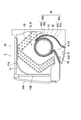
- FIG. 2 is a cross-sectional view showing the air conditioner 5 when the air conditioning operation is stopped.
- FIG. 3 is a cross-sectional view showing the air conditioner 5 during the air conditioning operation.
- the air conditioning operation is, for example, a cooling operation, a heating operation, a dehumidifying operation, or a blowing operation.
- the air conditioner 5 performs air conditioning.
- the air conditioner 5 is installed on the upper part of the wall of the room of the building.
- the air conditioner 5 is an indoor unit.
- the air conditioner 5 is connected to the outdoor unit by piping.
- the outdoor unit is installed outdoors. Then, the refrigerant circulates between the air conditioner 5 and the outdoor unit through the piping.
- the outdoor unit includes a fan, a compressor, a heat exchanger, and various parts such as a four-way valve.
- the air conditioner 5 includes a cabinet 50, a filter 51, and a fan 53.
- the cabinet 50 is an example of a cabinet.
- the shape of the cabinet 50 is, for example, a rectangular parallelepiped.
- the cabinet 50 has an upper surface, a lower surface, a front surface, a back surface, a right side surface, and a left side surface. The back is mounted on the wall of the room.
- the cabinet 50 has a first suction port P1A, a second suction port P1B, an outlet P2, a flow passage G, a blower flap 54A, and a wind receiving flap 54B.
- the first suction port P1A is formed on the upper surface of the cabinet 50.
- the second suction port P1B is formed on the upper front surface of the cabinet 50.
- the air outlet P2 is formed on the lower surface of the cabinet 50. Then, inside the cabinet 50, a flow passage G from the first suction port P1A or the second suction port P1B to the outlet P2 is formed.
- the fan 53 is arranged in the flow passage G.
- the fan 53 sucks air into the flow passage G from the outside through the first suction port P1A or the second suction port P1B, and blows the sucked air from the flow passage G to the outside through the outlet P2.
- the fan 53 is, for example, a cross flow fan.
- the cross-flow fan is, for example, a substantially cylindrical impeller.
- the filter 51 is arranged at the first suction port P1A and the second suction port P1B.
- the filter 51 collects dust in the air in the room. Specifically, the filter 51 collects dust from the air passing through the first suction port P1A and the second suction port P1B.
- the blower flap 54A opens and closes the outlet P2. Specifically, the blower flap 54A moves to be in either an open state in which the air outlet P2 is opened and a closed state in which the air outlet P2 is closed. Specifically, the blower flap 54A is opened during the air conditioning operation. On the other hand, the blower flap 54A is closed when the air conditioning operation is stopped.
- the wind receiving flap 54B opens and closes the second suction port P1B. Specifically, the wind receiving flap 54B moves to be in either an open state in which the second suction port P1B is opened or a closed state in which the second suction port P1B is closed. Specifically, the wind receiving flap 54B is opened during the air conditioning operation. On the other hand, the wind receiving flap 54B is closed when the air conditioning operation is stopped.
- the air conditioner 5 further includes a guide 55 forming a flow passage G.
- the flow passage G includes a first flow passage G1 and a second flow passage G2.
- the first flow passage G1 extends from the first suction port P1A and the second suction port P1B of the cabinet 50 to the back side of the cabinet 50 at the upper part of the cabinet 50.
- the second flow passage G2 is connected to the first flow passage G1 on the back side of the cabinet 50, and extends toward the air outlet P2 of the cabinet 50 at the lower part of the cabinet 50.
- the second flow passage G2 is formed by the guide 55.
- the fan 53 is arranged at a connecting portion connecting the first flow passage G1 and the second flow passage G2.
- the air conditioner 5 further includes a heat exchanger 52.
- the heat exchanger 52 is arranged in the first flow passage G1.
- the heat exchanger 52 exchanges heat. Specifically, the heat exchanger 52 transfers heat energy between the air flowing through the first flow passage G1 and the refrigerant supplied from the outdoor unit.
- the air conditioner 5 further includes a photocatalyst layer 60 and a light source unit 70.
- the photocatalyst layer 60 is located in the flow path G.
- the photocatalyst layer 60 has a first photocatalyst layer 60a and a second photocatalyst layer 60b.
- the first photocatalyst layer 60a is located in the second flow passage G2.
- the first photocatalyst layer 60a is formed on the inner surface of the guide 55.
- the second photocatalyst layer 60b is located on the surface of the fan 53.
- the photocatalyst layer 60 contains a photocatalyst.
- the photocatalyst is preferably excited by visible light.
- Examples of the photocatalyst include visible light responsive photocatalysts, and examples thereof include titanium oxide particles carrying a photocatalyst having a photosensitizing effect such as tungsten.
- the first photocatalyst layer 60a includes, for example, a top coat layer 61a and an undercoat layer 62a.
- the second photocatalyst layer 60b includes, for example, a top coat layer 61b and an undercoat layer 62b.
- the photocatalyst is contained in the top coat layer 61a and the top coat layer 61b.
- the undercoat layer 62a is located between the topcoat layer 61a and the guide 55. Further, the undercoat layer 62b is located between the topcoat layer 61b and the surface of the fan 53.
- the undercoat layer 62a and the undercoat layer 62b contain, for example, a silicone resin.
- the light source unit 70 is housed in the cabinet 50.
- the light source unit 70 is provided on the inner surface of the blower flap 54A, for example. Specifically, when the blower flap 54A is in the closed state, the inner surface of the blower flap 54A faces the second flow passage G2 near the outlet P2. As a result, the light source unit 70 is housed in the cabinet 50 so as to face the second flow passage G2 and the fan 53 near the outlet P2.
- the light source unit 70 emits light to the photocatalyst layer 60.
- the light source unit 70 emits visible light, for example.
- the light source unit 70 is, for example, a plurality of LED (light emitting diodes) elements.
- the light source unit 70 preferably has an illuminance of 10 klx or more and 100 klx or less in terms of activating the photocatalyst with visible light.
- the LED element includes a phosphor and a blue light source. Then, the blue light source emits excitation light of 450 nm to the phosphor to emit white light. Further, the LED element emits white light of 3000 lm or more and 5000 lm or less.
- the flow passage G can be irradiated with light.
- the photocatalyst contained in the photocatalyst layer 60 located in the flow path G can be excited. Therefore, the excited photocatalyst generates OH radicals from the water molecules existing in the flow path G. As a result, bacteria and fungi existing in the flow path G can be sterilized and eradicated by OH radicals.
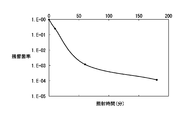
- FIG. 4 is a graph showing the bactericidal and sterilizing effects of Cladosporium.
- the vertical axis represents the residual bacterial rate and the horizontal axis represents the irradiation time.
- Black mold is a typical fungus that grows around water such as dew condensation, and most of the black mold in the home is Cladosporium.
- an LED light source including a phosphor and a blue light source that emits light of 450 nm as excitation light with respect to the phosphor was used as the excitation light source.
- a sterilization effect on the order of cube was confirmed.
- the photocatalyst is excited by visible light to generate OH radicals.
- general bacteria and fungi can be sterilized and eradicated without affecting the synthetic resin forming the fan 53 and the guide 55 and the human eye.
- the light source unit 70 is provided on the inner surface of the blower flap 54A, bacteria and fungi existing in the second flow passage G2 near the outlet P2 can be sterilized and sterilized.
- the undercoat layer 62a is located between the guide 55 and the topcoat layer 61a, the adhesion between the guide 55 and the topcoat layer 61a can be improved. Further, since the undercoat layer 62b is located between the fan 53 and the topcoat layer 61b, the adhesion between the fan 53 and the topcoat layer 61b can be improved. Further, it is possible to prevent the photocatalyst in the excited state from affecting the synthetic resin forming the fan 53 and the guide 55.
- FIG. 5 is a block diagram showing an air conditioner 5.
- the air conditioner 5 further includes a control unit 56, a storage unit 57, and a drive unit 58.
- the storage unit 57 is a storage device and stores data and computer programs.
- the storage device includes a main storage device such as a semiconductor memory and an auxiliary storage device such as a semiconductor memory and / or a hard disk drive.
- the drive unit 58 drives the wind receiving flap 54B and the blowing flap 54A. Specifically, the wind receiving flap 54B and the blowing flap 54A are opened during the air conditioning operation. On the other hand, the wind receiving flap 54B and the blowing flap 54A are closed when the air conditioning operation is stopped.
- the control unit 56 controls the heat exchanger 52, the fan 53, the drive unit 58, and the light source unit 70.
- the control unit 56 includes a processor such as a CPU (Central Processing Unit).
- the processor of the control unit 56 executes a computer program stored in the storage device of the storage unit 57 to execute various controls.
- control unit 56 controls the heat exchanger 52, the fan 53, and the drive unit 58 when the execution signal for executing the air-conditioning operation is received. Specifically, the control unit 56 controls the drive unit 58 so that the wind receiving flap 54B and the blowing flap 54A open when the fan 53 is operated.
- control unit 56 controls the heat exchanger 52, the fan 53, the drive unit 58, and the light source unit 70. Specifically, the control unit 56 controls the drive unit 58 so that the wind receiving flap 54B and the blowing flap 54A close when the operation of the fan 53 is stopped. Further, the control unit 56 emits light from the light source unit 70 for a predetermined time.
- the predetermined time is, for example, 60 to 120 minutes.
- the blower flap 54A closes when the air conditioning operation is stopped. With the blower flap 54A closed, light is emitted from the light source unit 70. As a result, the light is applied to the second flow passage G2 and the fan 53 near the outlet P2. Therefore, it is possible to prevent bacteria and fungi from propagating in the second flow passage G2 and the fan 53 after the air conditioning operation is stopped.
- FIG. 6 is a flowchart showing the sterilization and sterilization operations of the air conditioner 5. As shown in FIG. 6, the process of the control unit 56 includes steps S101 to S106.
- step S101 the control unit 56 determines whether or not the execution signal has been received.
- step S101 If a negative determination is made in step S101 (No in step S101), the process returns to step S101.
- step S101 If an affirmative determination is made in step S101 (Yes in step S101), the process proceeds to step S102.
- step S102 the control unit 56 controls the drive unit 58 so that the wind receiving flap 54B and the blowing flap 54A open when the fan 53 is operated.
- step S103 the control unit 56 determines whether or not a stop signal has been received.
- step S103 If a negative determination is made in step S103 (No in step S103), the process returns to step S103.
- step S103 If an affirmative determination is made in step S103 (Yes in step S103), the process proceeds to step S104.
- step S104 the control unit 56 controls the drive unit 58 so that the wind receiving flap 54B and the blowing flap 54A are closed when the operation of the fan 53 is stopped.
- step S105 the control unit 56 emits light from the light source unit 70.
- step S106 the control unit 56 determines whether or not a predetermined time has elapsed.
- step S106 If a negative determination is made in step S106 (No in step S106), the process returns to step S106.
- step S106 If an affirmative determination is made in step S106 (Yes in step S106), the process ends.
- the second embodiment is mainly different from the first embodiment in that the light source unit 70 emits ultraviolet light.
- the difference between the second embodiment and the first embodiment will be mainly described.
- the photocatalyst layer 60 contains a photocatalyst.
- the photocatalyst is preferably excited by ultraviolet light.
- Examples of the photocatalyst include a plurality of titanium oxide particles.
- the light source unit 70 emits light to the photocatalyst layer 60.
- the light source unit 70 emits ultraviolet light, for example.
- the light source unit 70 is, for example, a plurality of LED elements.
- the photocatalyst can be excited by ultraviolet light having strong energy. Therefore, a large amount of OH radicals are generated in a short time by the excited photocatalyst. As a result, general bacteria and fungi existing in the flow passage G can be sterilized and sterilized by a large amount of OH radicals in a short time.
- FIG. 7 is a graph showing the bactericidal and sterilizing actions of Cladosporium.
- the vertical axis represents the residual bacterial rate and the horizontal axis represents the irradiation time.
- FIG. 7 a near-ultraviolet light source that emits light of 260 nm was used as the excitation light source. As shown in FIG. 7, it was confirmed that the sterilization effect (sterilization rate 99.9% or more) on the order of the third power was obtained by light irradiation for 5 to 10 minutes at an illuminance of 500 cd / cm 2 and a distance of 10 cm. ..
- the third embodiment is mainly different from the first embodiment in that the surface of the light source unit 70 is substantially spherically processed.
- the points that the third embodiment is different from the first embodiment will be mainly described.
- the shape of the surface of the light source unit 70 is a spherical surface. More preferably, the surface of the light source unit 70 is processed into a gentle spherical surface.
- the light source unit 70 includes a light source 71 that emits visible light and a transparent cover 72 that houses the light source 71.
- the light source 71 is, for example, a plurality of LED elements.
- the light source unit 70 since the surface shape of the light source unit 70 is spherical, the light source unit 70 does not hinder the air from flowing through the flow passage G during the air conditioning operation.
- the fourth embodiment is mainly different from the first embodiment in that the fourth embodiment includes an ion generator 300.
- the points that the fourth embodiment is different from the first embodiment will be mainly described.
- the air conditioner 5 further includes an ion generator 300.
- the ion generator 300 includes a discharge electrode, an induction electrode, and a high voltage generation circuit that applies a high voltage.
- a discharge occurs between the discharge electrode and the induction electrode.
- OH radicals are generated from water molecules by electric discharge.
- the moisture adhering to the guide 55 should be reduced in advance by the air conditioning operation of the air conditioner 5.
- the effect of causing a water-repellent action on the surface of the photocatalyst layer 60 and improving quick-drying can be expected.
- the ion generator 300 is moved after sterilizing with a photocatalyst for a certain period of time, but the order is not necessarily limited to that.
- general bacteria and fungi can be sterilized and eradicated by OH radicals from the ion generator 300.
- the present invention provides an air conditioner and has industrial applicability.
- Air conditioner 50
- Cabinet Heat exchanger 53
- Fan 54A Blower flap 55
- Guide 56
- Control unit 58
- Photocatalyst layer 60a First photocatalyst layer 60b Second photocatalyst layer 70
- Light source unit 71
- Light source 72 Cover 300 Ion generator G flow path G1 1st flow passage G2 2nd flow passage P1A 1st suction port P1B 2nd suction port P2 Air outlet
Landscapes
- Engineering & Computer Science (AREA)
- Chemical & Material Sciences (AREA)
- Combustion & Propulsion (AREA)
- Mechanical Engineering (AREA)
- General Engineering & Computer Science (AREA)
- Air Filters, Heat-Exchange Apparatuses, And Housings Of Air-Conditioning Units (AREA)
- Disinfection, Sterilisation Or Deodorisation Of Air (AREA)
Abstract
本発明の目的は、流通路に存在する一般細菌及び真菌を殺菌及び除菌できる空気調和機を提供することにある。 空気調和機(5)は、筐体(50)と、光触媒層(60)と、光源部(70)とを備える。筐体(50)は、空気が流通する流通路Gを有する。光触媒層(60)は、流通路Gに位置する。光源部(70)は、筐体(50)に収容されている。光触媒層(60)は、光触媒を含有する。光源部(70)は、光触媒層(60)に対して光を出射する。また、光源部(70)は、可視光を出射し、光触媒は、可視光によって励起する。空気調和機(5)は、流通路Gに設けられたファン(53)を更に備える。
Description
本発明は、空気調和機に関する。
特許文献1に記載された空気調和機は、室内ユニットと、吸込部とを備える。吸込部の表面は、光触媒層からなる。室内の照明灯の光が光触媒層に照射されて、光触媒が励起する。その結果、光触媒が活性化して、臭い成分を分解する。
しかしながら、特許文献1に記載された空気調和機では、室内の照明灯の光が照射される領域は、吸込部を含む筐体の外面である。よって、筐体内に存在する臭い成分を含む低分子量の成分を分解できなかった。特に、流通路に存在する一般細菌及び真菌を殺菌及び除菌できなかった。
本発明の目的は、流通路に存在する一般細菌及び真菌を殺菌及び除菌できる空気調和機を提供することにある。
本発明の一局面によれば、空気調和機は、筐体と、光触媒層と、光源部とを備える。前記筐体は、空気が流通する流通路を有する。前記光触媒層は、前記流通路に位置する。前記光触媒層は、光触媒を含有する。前記光源部は、前記筐体に収容されている。前記光源部は、前記光触媒層に対して光を出射する。
本発明の空気調和機によれば、流通路に存在する一般細菌及び真菌を殺菌及び除菌できる。
以下、本発明の実施形態について、図面を参照しながら説明する。なお、図中、同一又は相当部分については同一の参照符号を付して説明を繰り返さない。また、図中、光触媒層の断面をハッチングで示す。
(実施形態1)
図1から図3を参照して、本発明の実施形態1に係る空気調和機5を説明する。図1は、空気調和のための運転(以下、「空気調和運転」と記載する。)停止時の空気調和機5を示す斜視図である。図2は、空気調和運転停止時の空気調和機5を示す断面図である。図3は、空気調和運転時の空気調和機5を示す断面図である。空気調和運転は、例えば、冷房運転、暖房運転、除湿運転、又は、送風運転である。
図1から図3を参照して、本発明の実施形態1に係る空気調和機5を説明する。図1は、空気調和のための運転(以下、「空気調和運転」と記載する。)停止時の空気調和機5を示す斜視図である。図2は、空気調和運転停止時の空気調和機5を示す断面図である。図3は、空気調和運転時の空気調和機5を示す断面図である。空気調和運転は、例えば、冷房運転、暖房運転、除湿運転、又は、送風運転である。
図1に示すように、空気調和機5は空気調和を行う。空気調和機5は、建造物の部屋の壁上部に設置される。空気調和機5は室内機である。なお、空気調和機5は、配管によって室外機と接続される。室外機は室外に設置される。そして、配管を通して、空気調和機5と室外機との間で冷媒が循環する。室外機は、ファンと、圧縮機と、熱交換器と、四方弁のような各種部品とを備える。
図1から図3に示すように、空気調和機5は、キャビネット50と、フィルター51と、ファン53とを含む。キャビネット50は、筐体の一例である。キャビネット50の形状は、例えば、直方体である。具体的には、キャビネット50は、上面と、下面と、前面と、背面と、右側面と、左側面とを有する。背面は、部屋の壁に取付けられる。
キャビネット50は、第1吸込口P1Aと、第2吸込口P1Bと、吹出口P2と、流通路Gと、送風フラップ54Aと、受風フラップ54Bとを有する。
第1吸込口P1Aは、キャビネット50の上面に形成される。第2吸込口P1Bは、キャビネット50の前面上部に形成される。吹出口P2は、キャビネット50の下面に形成される。そして、キャビネット50の内部には、第1吸込口P1A又は第2吸込口P1Bから吹出口P2に至る流通路Gが形成される。
流通路Gには、空気が流通する。ファン53は、流通路Gに配置される。
ファン53は、空気調和運転時に、第1吸込口P1A又は第2吸込口P1Bを通して外部から流通路Gに空気を吸い込み、吸い込んだ空気を、吹出口P2を通して流通路Gから外部に吹き出す。ファン53は、例えば、クロスフローファンである。クロスフローファンは、例えば、略円筒体の羽根車である。
フィルター51は、第1吸込口P1A及び第2吸込口P1Bに配置される。フィルター51は室内の空気中の塵埃を集塵する。具体的には、フィルター51は、第1吸込口P1A及び第2吸込口P1Bを通過する空気から塵埃を集塵する。
送風フラップ54Aは、吹出口P2を開閉する。詳細には、送風フラップ54Aは、移動して、吹出口P2を開く開状態と、吹出口P2を閉める閉状態とのうちのいずれかの状態となる。具体的には、送風フラップ54Aは、空気調和運転時に開状態となる。一方、送風フラップ54Aは、空気調和運転停止時に閉状態となる。
受風フラップ54Bは、第2吸込口P1Bを開閉する。詳細には、受風フラップ54Bは、移動して、第2吸込口P1Bを開く開状態と、第2吸込口P1Bを閉める閉状態とのうちのいずれかの状態となる。具体的には、受風フラップ54Bは、空気調和運転時に開状態となる。一方、受風フラップ54Bは、空気調和運転停止時に閉状態となる。
ここで、流通路Gを詳細に説明する。空気調和機5は、流通路Gを形成するガイド55を更に備える。流通路Gは、第1流通路G1と第2流通路G2とを含む。
第1流通路G1は、キャビネット50の上部で、キャビネット50の第1吸込口P1A及び第2吸込口P1Bから、キャビネット50の背面側まで延びている。
第2流通路G2は、キャビネット50の背面側で第1流通路G1に接続され、キャビネット50の下部で、キャビネット50の吹出口P2に向かって延びる。第2流通路G2は、ガイド55によって形成される。
ファン53は、第1流通路G1と第2流通路G2とを接続する接続部に配置されている。
空気調和機5は、熱交換器52を更に備える。熱交換器52は、第1流通路G1に配置されている。熱交換器52は、熱交換を行う。具体的には、熱交換器52は、第1流通路G1を流通する空気と、室外機から供給された冷媒との間で、熱エネルギーを伝達する。
空気調和機5は、光触媒層60と、光源部70とを更に含む。
光触媒層60は、流通路Gに位置する。光触媒層60は、第1光触媒層60aと、第2光触媒層60bとを有する。例えば、第1光触媒層60aは、第2流通路G2に位置する。具体的には、第1光触媒層60aは、ガイド55の内面に形成されている。更に、第2光触媒層60bは、ファン53の表面に位置する。
光触媒層60は、光触媒を含有する。光触媒は、可視光によって励起することが好ましい。光触媒としては、可視光応答型光触媒が挙げられ、例えば、タングステン等、光増感作用を有するものを担持させた酸化チタン粒子が挙げられる。
第1光触媒層60aは、例えば、トップコート層61aとアンダーコート層62aとを含む。また、第2光触媒層60bは、例えば、トップコート層61bとアンダーコート層62bとを含む。光触媒は、トップコート層61a及びトップコート層61bに含有されている。
アンダーコート層62aは、トップコート層61aとガイド55との間に位置する。また、アンダーコート層62bは、トップコート層61bとファン53の表面との間に位置する。アンダーコート層62a及びアンダーコート層62bは、例えば、シリコーン樹脂を含有する。
光源部70は、キャビネット50に収容されている。光源部70は、例えば、送風フラップ54Aの内面に設けられている。詳細には、送風フラップ54Aが閉状態であるときに、送風フラップ54Aの内面は吹出口P2付近の第2流通路G2に対向する。その結果、光源部70は、吹出口P2付近の第2流通路G2及びファン53に対向するように、キャビネット50に収容される。
光源部70は、光触媒層60に対して光を出射する。光源部70は、例えば、可視光を出射する。光源部70は、例えば、複数のLED(light emitting diode)素子である。光源部70として、可視光で光触媒を活性化させる点で、10klx以上100klx以下の照度があることが好ましい。例えば、LED素子は、蛍光体と、青色光源とを含む。そして、青色光源が蛍光体に対し450nmの励起光を出射して、白色光を出射する。また、LED素子は、3000lm以上5000lm以下の白色光を出射する。
従って、実施形態1によれば、光源部70がキャビネット50に収容されているため、流通路Gに光を照射できる。その結果、流通路Gに位置する光触媒層60に含有される光触媒を励起できる。よって、励起状態の光触媒によって、流通路Gに存在する水分子からOHラジカルを発生させる。その結果、OHラジカルによって、流通路Gに存在する細菌及び真菌を殺菌及び除菌できる。
ここで、図4を参照して、実施形態1に係る黒カビの殺菌及び除菌作用について説明する。図4は、クラドスポリウムの殺菌及び除菌作用を示すグラフである。図4において、縦軸は残留菌率を示し、横軸は照射時間を示す。なお、黒カビは結露など水回りに生育する真菌の代表格であり、家庭内における黒カビの殆どは、クラドスポリウムである。
図4では、励起光源として、蛍光体と、蛍光体に対して励起光として450nmの光を出射する青色光源とを含むLED光源を用いた。図4に示すように、全光束5000lmの白色光を、距離10cm(照度10klx以上100klx以下)にて60分から120分、照射することにより、3乗オーダーの除菌効果(除菌率99.9%以上)があることを確認できた。
また、実施形態1によれば、可視光によって光触媒を励起させて、OHラジカルを発生させる。その結果、ファン53及びガイド55を形成する合成樹脂及びヒトの眼に影響を与えず、一般細菌及び真菌を殺菌及び除菌できる。
そして、実施形態1によれば、光源部70は送風フラップ54Aの内面に設けられているため、吹出口P2付近の第2流通路G2に存在する細菌及び真菌を殺菌及び除菌できる。
更に、実施形態1によれば、ガイド55とトップコート層61aとの間にアンダーコート層62aが位置するため、ガイド55とトップコート層61aとの密着性を高めることができる。また、ファン53とトップコート層61bとの間にアンダーコート層62bが位置するため、ファン53とトップコート層61bとの密着性を高めることができる。更に、励起状態の光触媒によって、ファン53及びガイド55を形成する合成樹脂に影響を与えることを防止できる。
続けて、図5を参照して、実施形態1に係る空気調和機5を説明する。図5は、空気調和機5を示すブロック図である。図5に示すように、空気調和機5は、制御部56と、記憶部57と、駆動部58とを更に含む。記憶部57は、記憶装置であり、データ及びコンピュータープログラムを記憶する。記憶装置は、半導体メモリーのような主記憶装置と、半導体メモリー及び/又はハードディスクドライブのような補助記憶装置とを含む。
駆動部58は、受風フラップ54B及び送風フラップ54Aを駆動する。具体的には、受風フラップ54B及び送風フラップ54Aは、空気調和運転時に開状態となる。一方、受風フラップ54B及び送風フラップ54Aは、空気調和運転停止時に閉状態となる。
制御部56は、熱交換器52、ファン53、駆動部58及び光源部70を制御する。制御部56はCPU(Central Processing Unit)のようなプロセッサーを含む。制御部56のプロセッサーは、記憶部57の記憶装置が記憶しているコンピュータープログラムを実行して、各種制御を実行する。
詳細には、制御部56は、空気調和運転を実行する実行信号を受け付けたときに、熱交換器52、ファン53及び駆動部58を制御する。具体的には、制御部56は、ファン53を作動させたときに、受風フラップ54B及び送風フラップ54Aが開くように、駆動部58を制御する。
そして、制御部56は、空気調和運転停止を実行する停止信号を受け付けたときに、熱交換器52、ファン53、駆動部58及び光源部70を制御する。具体的には、制御部56は、ファン53の作動を停止したときに、受風フラップ54B及び送風フラップ54Aが閉じるように、駆動部58を制御する。更に、制御部56は、光源部70から光を所定時間、出射させる。所定時間は、例えば、60分から120分である。
従って、実施形態1によれば、空気調和運転停止時に送風フラップ54Aが閉じる。送風フラップ54Aが閉じた状態で、光源部70から光を出射させる。その結果、光は、吹出口P2付近の第2流通路G2及びファン53に照射される。よって、空気調和運転停止後に細菌及び真菌が第2流通路G2及びファン53に繁殖することを防止できる。
次に、図6を参照して、空気調和機5が細菌及び真菌を殺菌及び除菌するときの処理を説明する。図6は、空気調和機5の殺菌及び除菌動作を示すフローチャートである。図6に示すように、制御部56の処理は、ステップS101~ステップS106を含む。
ステップS101において、制御部56は、実行信号を受信したか否かを判定する。
ステップS101で否定判定(ステップS101でNo)がされた場合は、処理がステップS101に戻る。
一方、ステップS101で肯定判定(ステップS101でYes)がされた場合は、処理がステップS102に進む。
ステップS102において、制御部56は、ファン53を作動させたときに、受風フラップ54B及び送風フラップ54Aが開くように、駆動部58を制御する。
ステップS103において、制御部56は、停止信号を受信したか否かを判定する。
ステップS103で否定判定(ステップS103でNo)がされた場合は、処理がステップS103に戻る。
一方、ステップS103で肯定判定(ステップS103でYes)がされた場合は、処理がステップS104に進む。
ステップS104において、制御部56は、ファン53の作動を停止したときに、受風フラップ54B及び送風フラップ54Aが閉じるように、駆動部58を制御する。
ステップS105において、制御部56は、光源部70から光を出射させる。
ステップS106において、制御部56は、所定時間が経過したか否かを判定する。
ステップS106で否定判定(ステップS106でNo)がされた場合は、処理がステップS106に戻る。
一方、ステップS106で肯定判定(ステップS106でYes)がされた場合は、処理が終了する。
(実施形態2)
次に、図1から図5を参照して、本発明の実施形態2に係る空気調和機5を説明する。実施形態2が、光源部70は紫外光を出射する点で、実施形態2は実施形態1と主に異なる。以下、実施形態2が実施形態1と異なる点を主に説明する。
次に、図1から図5を参照して、本発明の実施形態2に係る空気調和機5を説明する。実施形態2が、光源部70は紫外光を出射する点で、実施形態2は実施形態1と主に異なる。以下、実施形態2が実施形態1と異なる点を主に説明する。
光触媒層60は、光触媒を含有する。光触媒は、紫外光によって励起することが好ましい。光触媒としては、例えば、複数の酸化チタン粒子が挙げられる。
光源部70は、光触媒層60に対して光を出射する。光源部70は、例えば、紫外光を出射する。光源部70は、例えば、複数のLED素子である。
従って、実施形態2によれば、強いエネルギーを有する紫外光によって光触媒を励起できる。よって、励起状態の光触媒によって、多量のOHラジカルを短時間に発生させる。その結果、多量のOHラジカルによって、短時間で流通路Gに存在する一般細菌及び真菌を殺菌及び除菌できる。
ここで、図7を参照して、実施形態2に係る黒カビの殺菌及び除菌作用について説明する。図7は、クラドスポリウムの殺菌及び除菌作用を示すグラフである。図7において、縦軸は残留菌率を示し、横軸は照射時間を示す。
図7では、励起光源として、260nmの光を出射する近紫外光源を用いた。図7に示すように、照度500cd/cm2、距離10cmにて5分から10分の光照射により、3乗オーダーの除菌効果(除菌率99.9%以上)があることを確認できた。
(実施形態3)
次に、図8を参照して、本発明の実施形態3に係る空気調和機5を説明する。実施形態3が、光源部70の表面は、略球面加工されている点で、実施形態3は実施形態1と主に異なる。以下、実施形態3が実施形態1と異なる点を主に説明する。
次に、図8を参照して、本発明の実施形態3に係る空気調和機5を説明する。実施形態3が、光源部70の表面は、略球面加工されている点で、実施形態3は実施形態1と主に異なる。以下、実施形態3が実施形態1と異なる点を主に説明する。
図8に示すように、光源部70の表面の形状は、球面である。より好ましくは、光源部70の表面は、なだらかな略球面加工されている。光源部70は、可視光を出射する光源71と、光源71を収容する透明なカバー72とを備える。光源71は、例えば、複数のLED素子である。
従って、実施形態3によれば、光源部70の表面の形状は、球面であるため、空気調和運転時に空気が流通路Gを流通することを、光源部70が阻害しない。
(実施形態4)
次に、図9を参照して、本発明の実施形態4に係る空気調和機5を説明する。実施形態4が、イオン発生器300を備える点で、実施形態4は実施形態1と主に異なる。以下、実施形態4が実施形態1と異なる点を主に説明する。
次に、図9を参照して、本発明の実施形態4に係る空気調和機5を説明する。実施形態4が、イオン発生器300を備える点で、実施形態4は実施形態1と主に異なる。以下、実施形態4が実施形態1と異なる点を主に説明する。
図9に示すように、空気調和機5は、イオン発生器300を更に備える。
イオン発生器300は、放電電極と、誘導電極と、高電圧を印加する高電圧発生回路とを備える。高電圧発生回路が高電圧を印加すると、放電電極と誘導電極との間に放電が生じる。放電によって、水分子からOHラジカルを発生させる。
かかるイオン発生器300から発生されるイオン種(OHラジカル)は、水分と接触すると即時に失活するため、空気調和機5の空気調和運転によりガイド55に付着した水分は予め低減しておくことが好ましいが、ガイド55等に塗布した光触媒層60に対し光を照射することで、光触媒層60の表面に撥水作用を起こして速乾性を上げるという効果を期待できる。
従って、除菌効果を最大化させる場合、イオン発生器300は、光触媒にて一定時間除菌を行った後に、可動されることが望ましいが、順番としては必ずしもそれに限定されるものではない。
従って、実施形態4によれば、イオン発生器300からのOHラジカルによっても一般細菌及び真菌を殺菌及び除菌できる。
以上、図面を参照しながら本発明の実施形態について説明した。但し、本発明は、上記の実施形態に限られるものではなく、その要旨を逸脱しない範囲で種々の態様において実施することが可能である。また、上記の実施形態に開示されている複数の構成要素を適宜組み合わせることによって、種々の発明の形成が可能である。例えば、実施形態に示される全構成要素から幾つかの構成要素を削除してもよい。更に、異なる実施形態にわたる構成要素を適宜組み合わせてもよい。図面は、理解しやすくするために、それぞれの構成要素を主体に模式的に示しており、図示された各構成要素の厚み、長さ、個数、間隔等は、図面作成の都合上から実際とは異なる場合もある。また、上記の実施形態で示す各構成要素の材質、形状、寸法等は一例であって、特に限定されるものではなく、本発明の効果から実質的に逸脱しない範囲で種々の変更が可能である。
実施形態1と実施形態2と実施形態3と実施形態4とのうちの2以上の特徴を組み合わせてもよい。
本発明は、空気調和機を提供するものであり、産業上の利用可能性を有する。
5 空気調和機
50 キャビネット
52 熱交換器
53 ファン
54A 送風フラップ
55 ガイド
56 制御部
58 駆動部
60 光触媒層
60a 第1光触媒層
60b 第2光触媒層
70 光源部
71 光源
72 カバー
300 イオン発生器
G 流通路
G1 第1流通路
G2 第2流通路
P1A 第1吸込口
P1B 第2吸込口
P2 吹出口
50 キャビネット
52 熱交換器
53 ファン
54A 送風フラップ
55 ガイド
56 制御部
58 駆動部
60 光触媒層
60a 第1光触媒層
60b 第2光触媒層
70 光源部
71 光源
72 カバー
300 イオン発生器
G 流通路
G1 第1流通路
G2 第2流通路
P1A 第1吸込口
P1B 第2吸込口
P2 吹出口
Claims (7)
- 空気が流通する流通路を有する筐体と、
前記流通路に位置し、光触媒を含有する光触媒層と、
前記筐体に収容され、前記光触媒層に対して光を出射する光源部と
を備える、空気調和機。 - 前記光源部は、可視光を出射し、
前記光触媒は、前記可視光によって励起する、請求項1に記載の空気調和機。 - 前記光源部は、紫外光を出射し、
前記光触媒は、前記紫外光によって励起する、請求項1又は請求項2に記載の空気調和機。 - 前記流通路に設けられたファンを更に備え、
前記筐体は、
前記ファンによって前記流通路に前記空気を吸込む吸込口と、
前記ファンによって前記流通路から前記空気を吹出す吹出口と、
前記吹出口を開閉する送風フラップと
を更に有し、
前記光触媒層は、第1光触媒層と第2光触媒層とを有し、
前記第1光触媒層は、前記流通路を形成するガイドの表面に位置し、
前記第2光触媒層は、前記ファンの表面に位置し、
前記光源部は、前記送風フラップの内面に設けられている、請求項1から請求項3のいずれか1項に記載の空気調和機。 - 前記光源部の表面が、略球面加工されている、請求項4に記載の空気調和機。
- 前記送風フラップを駆動する駆動部と、
前記ファン、前記駆動部及び前記光源部を制御する制御部と
を更に備え、
前記制御部は、
前記ファンを作動させたときに、前記送風フラップが開くように、前記駆動部を制御し、
前記ファンの作動を停止したときに、前記送風フラップが閉じるように、前記駆動部を制御するとともに、前記光源部から前記光を出射させる、請求項4又は請求項5に記載の空気調和機。 - 前記筐体内に設けられ、イオンを発生させるイオン発生器を更に備える、請求項1から請求項6のいずれか1項に記載の空気調和機。
Priority Applications (1)
| Application Number | Priority Date | Filing Date | Title |
|---|---|---|---|
| JP2021507374A JPWO2020189682A1 (ja) | 2019-03-20 | 2020-03-17 |
Applications Claiming Priority (2)
| Application Number | Priority Date | Filing Date | Title |
|---|---|---|---|
| JP2019-052805 | 2019-03-20 | ||
| JP2019052805 | 2019-03-20 |
Publications (1)
| Publication Number | Publication Date |
|---|---|
| WO2020189682A1 true WO2020189682A1 (ja) | 2020-09-24 |
Family
ID=72520133
Family Applications (1)
| Application Number | Title | Priority Date | Filing Date |
|---|---|---|---|
| PCT/JP2020/011747 Ceased WO2020189682A1 (ja) | 2019-03-20 | 2020-03-17 | 空気調和機 |
Country Status (3)
| Country | Link |
|---|---|
| JP (1) | JPWO2020189682A1 (ja) |
| TW (1) | TW202034967A (ja) |
| WO (1) | WO2020189682A1 (ja) |
Cited By (4)
| Publication number | Priority date | Publication date | Assignee | Title |
|---|---|---|---|---|
| WO2022068582A1 (zh) * | 2020-11-05 | 2022-04-07 | 青岛海尔空调器有限总公司 | 用于空调器的除菌模块及空调器 |
| CN114427711A (zh) * | 2020-10-29 | 2022-05-03 | 夏普株式会社 | 空气调节机 |
| JP2022097449A (ja) * | 2020-12-18 | 2022-06-30 | エルジー エレクトロニクス インコーポレイティド | 空気調和機 |
| CN115111655A (zh) * | 2021-03-18 | 2022-09-27 | 东芝生活电器株式会社 | 空调装置 |
Citations (8)
| Publication number | Priority date | Publication date | Assignee | Title |
|---|---|---|---|---|
| JPH1085606A (ja) * | 1996-09-11 | 1998-04-07 | Toshiba Lighting & Technol Corp | 光触媒体、光触媒フィルタ、光触媒装置、空気調和装置、空気清浄機および空気循環機 |
| JPH11182883A (ja) * | 1997-12-19 | 1999-07-06 | Daikin Ind Ltd | 空気調和機 |
| JP2000320855A (ja) * | 1999-05-07 | 2000-11-24 | Sharp Corp | 送風機ならびに該送風機を備えた空気調和機および空気清浄機 |
| JP2000320854A (ja) * | 1999-05-13 | 2000-11-24 | Sharp Corp | 空気調和機の室内機 |
| JP2006098037A (ja) * | 2004-09-03 | 2006-04-13 | Fujitsu General Ltd | 空気調和機 |
| JP2008008564A (ja) * | 2006-06-30 | 2008-01-17 | Fujitsu General Ltd | 空気調和機 |
| JP2011226717A (ja) * | 2010-04-21 | 2011-11-10 | Hitachi Appliances Inc | 空気調和機 |
| JP2015187543A (ja) * | 2015-07-30 | 2015-10-29 | 日立アプライアンス株式会社 | 空気調和機 |
-
2020
- 2020-03-12 TW TW109108260A patent/TW202034967A/zh unknown
- 2020-03-17 WO PCT/JP2020/011747 patent/WO2020189682A1/ja not_active Ceased
- 2020-03-17 JP JP2021507374A patent/JPWO2020189682A1/ja active Pending
Patent Citations (8)
| Publication number | Priority date | Publication date | Assignee | Title |
|---|---|---|---|---|
| JPH1085606A (ja) * | 1996-09-11 | 1998-04-07 | Toshiba Lighting & Technol Corp | 光触媒体、光触媒フィルタ、光触媒装置、空気調和装置、空気清浄機および空気循環機 |
| JPH11182883A (ja) * | 1997-12-19 | 1999-07-06 | Daikin Ind Ltd | 空気調和機 |
| JP2000320855A (ja) * | 1999-05-07 | 2000-11-24 | Sharp Corp | 送風機ならびに該送風機を備えた空気調和機および空気清浄機 |
| JP2000320854A (ja) * | 1999-05-13 | 2000-11-24 | Sharp Corp | 空気調和機の室内機 |
| JP2006098037A (ja) * | 2004-09-03 | 2006-04-13 | Fujitsu General Ltd | 空気調和機 |
| JP2008008564A (ja) * | 2006-06-30 | 2008-01-17 | Fujitsu General Ltd | 空気調和機 |
| JP2011226717A (ja) * | 2010-04-21 | 2011-11-10 | Hitachi Appliances Inc | 空気調和機 |
| JP2015187543A (ja) * | 2015-07-30 | 2015-10-29 | 日立アプライアンス株式会社 | 空気調和機 |
Cited By (6)
| Publication number | Priority date | Publication date | Assignee | Title |
|---|---|---|---|---|
| CN114427711A (zh) * | 2020-10-29 | 2022-05-03 | 夏普株式会社 | 空气调节机 |
| WO2022068582A1 (zh) * | 2020-11-05 | 2022-04-07 | 青岛海尔空调器有限总公司 | 用于空调器的除菌模块及空调器 |
| JP2022097449A (ja) * | 2020-12-18 | 2022-06-30 | エルジー エレクトロニクス インコーポレイティド | 空気調和機 |
| JP7323596B2 (ja) | 2020-12-18 | 2023-08-08 | エルジー エレクトロニクス インコーポレイティド | 空気調和機 |
| US12078386B2 (en) | 2020-12-18 | 2024-09-03 | Lg Electronics Inc. | Air conditioner |
| CN115111655A (zh) * | 2021-03-18 | 2022-09-27 | 东芝生活电器株式会社 | 空调装置 |
Also Published As
| Publication number | Publication date |
|---|---|
| TW202034967A (zh) | 2020-10-01 |
| JPWO2020189682A1 (ja) | 2020-09-24 |
Similar Documents
| Publication | Publication Date | Title |
|---|---|---|
| WO2020189682A1 (ja) | 空気調和機 | |
| JP5899453B2 (ja) | オゾンとイオン風を発生させるオゾン・イオン発生装置およびそれを備える空気調和機 | |
| CN1281898C (zh) | 空调机 | |
| CN101227933B (zh) | 空气调节装置 | |
| JP2018162898A (ja) | 空気調和装置 | |
| KR101676817B1 (ko) | 방사형 공간 살균기 | |
| KR200439228Y1 (ko) | 광 플라즈마 살균부가 구비된 공기조화기 | |
| KR20180010762A (ko) | 공기 조화기 | |
| JP2020133915A (ja) | 空気調和装置の排水ユニットおよび室内機 | |
| JP4073824B2 (ja) | 送風装置 | |
| JP6480700B2 (ja) | 送風装置 | |
| CN216591955U (zh) | 空调室内机及具有其的空调器 | |
| KR20180010768A (ko) | 공기조화기 | |
| JP6974756B2 (ja) | 空気調和装置の室内ユニット | |
| JP4913705B2 (ja) | 給気口構造及び換気システム及びこれを用いた建物 | |
| JP5209753B2 (ja) | 換気システム | |
| CN111648979B (zh) | 自消毒风机及具有消毒功能的风扇 | |
| JP2006029665A (ja) | 天井埋設型または天井吊下型の空気調和装置 | |
| JP2020008181A (ja) | 空気調和機 | |
| JP2008116202A (ja) | イオン発生素子の取付構造及びこれを用いた送風構造並びに空調装置及び空調システム | |
| JP4674616B2 (ja) | 空気調和機 | |
| JP2004036922A (ja) | 空気調和機 | |
| JP2012042160A (ja) | 空気清浄機 | |
| JP5087121B2 (ja) | 給気口構造及び換気システム及びこれを用いた建物 | |
| KR20210091072A (ko) | 공기청정기 |
Legal Events
| Date | Code | Title | Description |
|---|---|---|---|
| 121 | Ep: the epo has been informed by wipo that ep was designated in this application |
Ref document number: 20773445 Country of ref document: EP Kind code of ref document: A1 |
|
| ENP | Entry into the national phase |
Ref document number: 2021507374 Country of ref document: JP Kind code of ref document: A |
|
| NENP | Non-entry into the national phase |
Ref country code: DE |
|
| 122 | Ep: pct application non-entry in european phase |
Ref document number: 20773445 Country of ref document: EP Kind code of ref document: A1 |