WO2020189149A1 - プランジャー押圧具 - Google Patents
プランジャー押圧具 Download PDFInfo
- Publication number
- WO2020189149A1 WO2020189149A1 PCT/JP2020/006309 JP2020006309W WO2020189149A1 WO 2020189149 A1 WO2020189149 A1 WO 2020189149A1 JP 2020006309 W JP2020006309 W JP 2020006309W WO 2020189149 A1 WO2020189149 A1 WO 2020189149A1
- Authority
- WO
- WIPO (PCT)
- Prior art keywords
- outer cylinder
- plunger
- hinge
- contact portion
- syringe
- Prior art date
- Legal status (The legal status is an assumption and is not a legal conclusion. Google has not performed a legal analysis and makes no representation as to the accuracy of the status listed.)
- Ceased
Links
Images






Classifications
-
- A—HUMAN NECESSITIES
- A61—MEDICAL OR VETERINARY SCIENCE; HYGIENE
- A61M—DEVICES FOR INTRODUCING MEDIA INTO, OR ONTO, THE BODY; DEVICES FOR TRANSDUCING BODY MEDIA OR FOR TAKING MEDIA FROM THE BODY; DEVICES FOR PRODUCING OR ENDING SLEEP OR STUPOR
- A61M5/00—Devices for bringing media into the body in a subcutaneous, intra-vascular or intramuscular way; Accessories therefor, e.g. filling or cleaning devices, arm-rests
- A61M5/14—Infusion devices, e.g. infusing by gravity; Blood infusion; Accessories therefor
- A61M5/142—Pressure infusion, e.g. using pumps
- A61M5/145—Pressure infusion, e.g. using pumps using pressurised reservoirs, e.g. pressurised by means of pistons
Definitions
- the present invention relates to a plunger presser for pressing a plunger of a syringe.
- a syringe prefilled syringe pre-filled with a chemical solution or the like
- a prefilled syringe includes an outer cylinder filled with a chemical solution, a gasket slidably housed in the outer cylinder, and a plunger for moving the gasket.
- the prefilled syringe may be filled with a highly viscous chemical solution, which causes a large resistance (pressing resistance) when pressing the plunger.
- Patent Document 1 Japanese Patent Application Laid-Open No. 2018-5007087
- Patent Document 1 includes a housing for holding a syringe and a plunger, a trigger held in the housing, and a lever including a cam communicating with the trigger. ..
- the cam communicates with the flange of the syringe.
- the upper end of the cam moves longitudinally towards the ejection end of the syringe.
- the plunger a pin provided integrally with the syringe
- the trigger and the lever are integrally configured, and they are configured to rotate around a pivot point (trigger pivot) provided between the trigger and the lever.
- the prefilled syringe is filled with various chemicals, and their characteristics such as viscosity are different. Further, the preferred resistance when operating various devices to press the plunger varies from operator to operator. However, in a device such as Patent Document 1, it is difficult to adjust the pressing resistance of the plunger in accordance with the chemical solution and the operator.
- the plunger moves toward the outer cylinder as the plunger is pressed.
- the distance between the fulcrum and the point of action changes while the plunger is pressed. That is, the distance between the fulcrum (trigger pivot) and the point of action (pin in contact with the cam) changes significantly. For this reason, the pressing resistance felt by the operator while pressing the plunger changes significantly.
- An object of the present invention is to provide a plunger pressing tool capable of adjusting the resistance at the time of pressing the plunger to a desired degree and suppressing a change in the resistance during pressing of the plunger.
- a plunger press for a syringe including an outer cylinder, a gasket slidably housed in the outer cylinder, and a plunger for moving the gasket.
- the plunger pressing tool is provided on a grip portion having a syringe mounting portion on which the syringe can be mounted on the outer cylinder, an extending portion extending rearward from the upper portion of the grip portion, and a rear portion of the extending portion.
- a main body portion having a hinge portion and a handle portion rotatably held by the hinge portion are provided.
- the handle portion includes a contact portion capable of contacting the rear end portion of the plunger of the mounted syringe and an operation portion extending downward from the contact portion, and the contact portion and the operation portion.
- the distance between the lower ends of the hinge portion is longer than the distance between the rotation axis of the hinge portion and the contact portion.
- the contact portion is rotatable in the direction of the outer cylinder mounted on the syringe mounting portion with the hinge portion as the center, and the contact portion is located directly below the hinge portion.
- a plunger pressing tool located on or below the extension line of the central axis of the outer cylinder mounted on the syringe mounting portion.
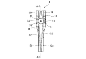
- FIG. 1 is a front view of a plunger pressing tool according to an embodiment of the present invention to which a syringe is attached, and is an explanatory view (at the start of operation) for explaining the operation of the plunger pressing tool.
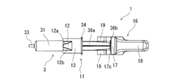
- FIG. 2 is a left side view of the plunger pressing tool shown in FIG.
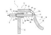
- FIG. 3 is a right side view of the plunger pressing tool shown in FIG.
- FIG. 4 is a plan view of the plunger pressing tool shown in FIG.
- FIG. 5 is a bottom view of the plunger pressing tool shown in FIG.
- FIG. 6 is a cross-sectional view taken along the line AA in FIG.
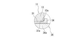
- FIG. 7 is an enlarged view of part B in FIG.
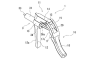
- FIG. 8 is a perspective view of the plunger pressing tool shown in FIG. FIG.
- FIG. 9 is another perspective view of the plunger pressing tool shown in FIG.
- FIG. 10 is an explanatory diagram (during operation) for explaining the operation of the plunger pressing tool of the present invention.
- FIG. 11 is an explanatory diagram (when the operation is completed) for explaining the operation of the plunger pressing tool of the present invention.
- FIG. 12 is a front view of the plunger pressing tool of another embodiment of the present invention to which the syringe is attached, and is an explanatory view (at the start of operation) for explaining the operation of the plunger pressing tool.
- FIG. 13 is an explanatory diagram (during operation) for explaining the operation of the plunger pressing tool shown in FIG.
- FIG. 14 is an explanatory diagram (when the operation is completed) for explaining the operation of the plunger pressing tool shown in FIG.
- FIG. 13 is an explanatory diagram (during operation) for explaining the operation of the plunger pressing tool shown in FIG.
- FIG. 15 is an enlarged explanatory view for explaining the locus of the contact portion during the operation of the plunger pressing tool shown in FIG.
- FIG. 16 is an enlarged explanatory view for explaining a locus of a contact portion during operation of the plunger pressing tool of another embodiment of the present invention.
- FIG. 17 is a front view of a plunger presser according to still another embodiment of the present invention to which a syringe is attached.
- the plunger pressing tool 1 of the present invention is a plunger pressing tool for a syringe including an outer cylinder, a gasket slidably housed in the outer cylinder, and a plunger for moving the gasket.
- FIG. 1 to 9 show a front view, a left side view, a right side view, a plan view, a bottom view, a cross-sectional view, and a perspective view of a state in which the syringe 3 is attached to the plunger pressing tool 1, respectively.
- the vertical direction in FIG. 1 is described as the vertical direction
- the horizontal direction is described as the front-rear direction (left side is front, right side is rear), but this does not necessarily mean the operating state of the plunger pressing tool 1. It does not specify.
- the plunger pressing tool 1 of the present invention includes a plunger pressing tool 1 for a syringe 3 including an outer cylinder 31, a gasket 35 slidably housed in the outer cylinder 31, and a plunger 36 for moving the gasket.
- the plunger pressing tool 1 includes a grip portion 12 having a syringe mounting portion 13 on which a syringe 3 can be mounted on an outer cylinder 31, an extending portion 14 extending rearward from the upper portion of the grip portion 12, and a rear portion of the extending portion 14.
- the main body portion 11 including the hinge portion 15 provided on the hinge portion 15 and the handle portion 16 rotatably held by the hinge portion 15 are provided.
- the handle portion 16 includes a contact portion 17 capable of contacting the rear end portion of the plunger 36 of the mounted syringe 3, and an operation portion 18 extending downward from the contact portion 17, and operates with the contact portion 17.
- the distance between the lower ends of the portion 18 is longer than the distance between the rotation axis of the hinge portion 15: A1 and the contact portion 17.
- the abutting portion 17 is rotatable in the direction of the outer cylinder 31 mounted on the syringe mounting portion 13 (outer cylinder direction) with the hinge portion 15 as the center, and is located directly below the hinge portion 15.
- the contact portion 17 is located on or slightly below the extension line of the central axis of the outer cylinder 31 mounted on the syringe mounting portion 13.
- the plunger pressing tool 1 includes a main body portion 11 and a handle portion 16.
- the main body 11 of the plunger pressing tool 1 includes a grip portion 12 including a syringe mounting portion 13, an extension portion 14 extending rearward from the upper portion of the grip portion 12, and a hinge portion 15 provided at the rear portion of the extension portion 14. And.
- the grip portion 12 has a substantially rod shape.
- a cylindrical syringe mounting portion 13 is provided on the upper portion of the grip portion 12 (a portion above the center of the grip portion 12 in the longitudinal direction).
- the syringe mounting portion 13 preferably regulates the rotation and detachment of the mounted outer cylinder 31.
- the inner diameter of the syringe mounting portion 13 is equal to or slightly larger than the outer diameter of the outer cylinder 31 of the syringe 3 described later.
- an annular minute convex portion 13a that slightly protrudes inward is formed on the inner peripheral surface of the rear portion of the syringe mounting portion 13, and is provided on the outer peripheral surface of the outer cylinder 31 of the syringe 3 described later.
- the outer cylinder 31 mounted on the syringe mounting portion 13 is restricted from rotating and detaching.
- the syringe mounting portion may be of a type in which the tip end surface of the flange portion of the outer cylinder of the syringe abuts on the rear end surface.
- the inner diameter of the syringe mounting portion 13 is preferably 15 to 32 mm. Further, the length of the syringe mounting portion 13 is preferably 5 to 50 mm. It is preferable that the syringe mounting portion 13 has a diameter slightly increased toward the rear end side.
- the main body portion 11 does not deform at the time of use at the grip portion 12 and at the boundary portion between the grip portion 12 and the syringe mounting portion 13. Therefore, the main body 11 is preferably formed of a metal material or a hard resin.
- the grip portion 12 preferably has a shape that is easy for the operator to grip.
- the grip portion 12 is provided with inclined surfaces 12a and 12b on both sides of the portion below the syringe mounting portion 13 of the grip portion 12 so that the cross-sectional area thereof gradually decreases toward the front. Further, it is preferable that the lower end portion of the grip portion 12 extends to a position equivalent to the lower end portion of the handle portion 16 described later. It is assumed that the operator grips the grip portion 12 extending downward from the syringe mounting portion 13, but the grip portion 12 is not limited to this, and the grip portion 12 is further inserted from the syringe mounting portion 13 so as to sandwich the syringe mounting portion 13. The operator may be configured to grip the portion extending upward.
- the extending portion 14 is integrally formed with the grip portion 12, and extends rearward from the upper part of the grip portion 12. It should be noted that the tip portion of the extension portion, which is a separate member, may be fixed to the upper end portion of the grip portion instead of the one-piece object.
- the extension portion 14 includes a portion extending upward from the syringe mounting portion 13 located at the upper end of the grip portion 12. The portion extending upward is formed to have the same width as the syringe mounting portion 13.
- the extending portion 14 includes a portion extending rearward from the upper end of the above-mentioned upward extending portion.
- the angle formed by the upwardly extending portion and the rearwardly extending portion of the extending portion 14 is a substantially right angle.
- a hinge portion 15 is provided at the rear portion of the extension portion 14, specifically, at the rear end portion.
- the hinge portion 15 has a structure for rotatably supporting the handle portion 16 to be attached around the rotation axis: A1 of the hinge portion 15, and a known bearing, a mechanism using a bearing or the like is used.
- the handle portion 16 is rotatably attached to the main body portion 11 of the plunger pressing tool 1 by the hinge portion 15.
- the hinge portion 15 is located above the extension line of the central axis of the syringe mounting portion 13 by a predetermined length, and is located behind the rear end of the syringe mounting portion 13 by a predetermined length.
- the hinge portion 15 is located obliquely above the rear end of the rear end of the syringe mounting portion 13.
- the distance between the hinge portion 15 and the extension line of the central axis of the syringe mounting portion 13 is preferably about 25 to 60 mm.
- the handle portion 16 is a substantially curved rod-shaped body.
- the handle portion 16 is attached to the hinge portion 15 by two arm portions 19 and 19 formed on the upper portion thereof.
- the distance between the two arm portions 19 and 19 is larger than the width of the extension portion 14.
- An interference avoidance notch 20 having a width dimension (dimension in the left-right direction in FIG. 3) larger than that of the extension portion 14 is formed between the arm portions 19 and 19.
- the handle portion 16 does not interfere with the extension portion 14 because the rear end portion of the extension portion 14 can enter the portion where the interference avoidance cutout portion 20 is formed.
- the handle portion 16 can be sufficiently rotated in the direction away from the outer cylinder 31 of the syringe 3 (counterclockwise direction in FIG. 1).
- a contact portion 17 is formed in an intermediate portion of the handle portion 16 (here, a portion above the center in the longitudinal direction of the handle portion 16).
- the contact portion 17 can come into contact with the rear end portion (pressing portion 36b) of the plunger 36 while the syringe 3 is held by the syringe mounting portion 13.
- the contact portion 17 is rotatable around the hinge portion 15 in the direction of the outer cylinder 31 mounted on the syringe mounting portion 13, and is as shown in FIG. 10 described later.
- the contact portion 17 when located directly below the hinge portion 15 is located on or slightly below the extension line of the central axis of the outer cylinder 31 mounted on the syringe mounting portion 13. ..
- the contact portion 17 is the syringe mounting portion 13. It is located substantially on the extension line (A2) of the central axis of the outer cylinder 31 mounted on the outer cylinder 31.
- the contact portion 17 is provided with recesses 17a and 17b at its upper portion and lower portion, respectively, and has a linear shape extending substantially parallel to the rotation axis of the hinge portion 15: A1 (in the direction perpendicular to the paper surface in FIG. 1) at the central portion. It has a top 17c.
- the contact portion 17 includes a linear top portion 17c extending substantially parallel to the rotation axis of the hinge portion 15: A1.
- the recess 17a is provided with an upper inclined surface having a linear top 17c as an apex.
- the recess 17b includes a lower inclined surface having a linear top 17c as an apex.
- the contact portion 17 moves on an arc whose radius is the distance between the contact portion 17 and the central axis of the hinge portion 15: A1 with the central axis of the hinge portion 15 as the center due to the rotation of the handle portion 16.
- the linear apex 17c is also centered on the central axis of the hinge portion 15: A1 by the rotation of the handle portion 16 while maintaining the state parallel to the center line of the hinge portion 15, and the linear apex 17c and the hinge.
- Central axis of unit 15 Moves on an arc whose radius is the distance between A1.
- the handle portion 16 includes an operation portion 18 extending downward from the contact portion 17.
- the contact portion 17 and the operation portion 18 are formed in that order in the same direction as viewed from the attachment portion to the hinge portion 15.
- the distance between the contact portion 17 (linear top portion 17c) and the lower end of the operation portion 18 is the rotation axis of the hinge portion 15: A1 and the contact portion 17.
- the distance between (linear tops 17c) is preferably twice or more, and more preferably four times or more.
- the distance between the contact portion 17 and the lower end of the operation portion 18: D2 is about four times the distance between the rotation axis of the hinge portion 15: A1 and the contact portion 17: D1. It has become.
- the operating portion 18 is curved rearward (in a direction away from the outer cylinder 31) from the contact portion 17 toward the lower end side.
- the handle is preferably curved as described above, but may be linear.
- the syringe 3 attached to the plunger pressing tool 1 includes a cylindrical outer cylinder 31, a gasket 35 slidably housed in the outer cylinder 31, and a plunger 36 for moving the gasket 35. ..
- the outer cylinder 31 is a substantially tubular member that houses the gasket 35 in a liquid-tight and slidable manner.
- a nozzle portion 33 having a small diameter is provided at the tip portion of the outer cylinder 31, and the tip end side portion of the outer cylinder 31 has a tapered shape in which the diameter is reduced toward the nozzle portion 33.
- a flange 34 is provided at the rear end of the outer cylinder 31.
- the flange 34 has an arcuate outer edge formed so as to project in the vertical direction from the entire circumference of the rear end of the outer cylinder 31.
- an annular micro-concave portion 31a that can engage with the micro-convex portion 13a formed in the syringe mounting portion 13 described above is formed.
- the gasket 35 is made of elastic rubber or synthetic resin. As shown in FIG. 6, the gasket 35 includes a substantially tubular main body portion 35a extending with substantially the same outer diameter, and a tapered closing portion 35b extending in the tip direction from the main body portion 35a. The outer surface of the main body 35a is in liquid-tight contact with the inner surface of the outer cylinder 31.
- the closed portion 35b of the gasket 35 has a shape (tapered shape) corresponding to the shape of the tip inner surface of the outer cylinder 31 so as not to form a gap between the two when it comes into contact with the tip inner surface of the outer cylinder 31. ..
- the plunger 36 is made of a hard or semi-hard resin.
- the plunger 36 includes a shaft portion 36a formed in a cross section and a disk-shaped pressing portion 36b provided at the rear end thereof.
- the tip of the shaft portion 36a is attached to the gasket 35.
- the gasket 35 moves integrally with the plunger 36.
- the space formed by the outer cylinder 31 and the gasket 35 is filled with the chemical solution 37 in advance. That is, the syringe 3 used in this embodiment is a so-called prefilled syringe.
- the plunger 36 and the gasket 35 move to the tip side of the syringe 3, and the chemical solution 37 is moved from the nozzle portion 33 provided at the tip portion of the outer cylinder 31. Is discharged.
- a highly viscous chemical solution particularly a chemical solution having a viscosity of 5 [mPa ⁇ s] or more, is filled as the chemical solution 37 filled in the space formed by the outer cylinder 31 and the gasket 35.
- the plunger presser of the present invention is effective.
- chemicals include medical liquids such as hyaluronic acid solutions, high-viscosity anticancer agents, high-viscosity biologics, and contrast agents.
- Such a syringe 3 is attached to the syringe mounting portion 13 of the plunger pressing tool 1. Specifically, the syringe 3 is inserted from the rear of the syringe mounting portion 13, and the outer cylinder 31 is held by the syringe mounting portion 13 with a certain width in the longitudinal direction. At this time, as shown in FIG. 7, the micro-convex portion 13a provided on the inner peripheral surface of the syringe mounting portion 13 and the micro-concave portion 31a provided on the outer peripheral surface of the outer cylinder 31 of the syringe 3 engage with each other. As a result, the syringe 3 is held more firmly, particularly immovably in the anteroposterior direction. Further, when the syringe 3 is attached to the plunger pressing tool 1, the front end surface of the flange 34 of the outer cylinder 31 is substantially in contact with the rear end surface of the syringe mounting portion 13.
- FIG. 1 shows the state at the start of operation of the plunger pressing tool 1 (at the start of pressing the plunger 36).
- the contact portion 17 of the handle portion 16 is in contact with the pressing portion 36b of the plunger 36. More specifically, the linear top portion 17c of the abutting portion 17 linearly abuts on the rear end surface of the pressing portion 36b.
- the contact portion 17 (the contact portion between the linear top portion 17c and the pressing portion 36b) is on the extension line: A2 of the central axis of the outer cylinder 31 in the vertical direction.
- the upper inclined surface of the recess 17a of the contact portion 17 is substantially in contact with the pressing portion 36b of the plunger 36.
- the operator grips the grip portion 12 and holds the plunger pressing tool 1 at a desired position. Then, by pressing an arbitrary position of the operation portion 18 of the handle portion 16 in the outer cylinder direction, the contact portion 17 rotates in the outer cylinder direction with the hinge portion 15 as the center. Along with this, the plunger 36 (and the gasket 35) moves toward the outer cylinder, and the chemical solution 37 filled in the syringe 3 is discharged from the nozzle portion 33.
- FIG. 10 shows a state in which the contact portion 17 is located directly below the hinge portion 15 (specifically, vertically below) while the plunger pressing tool 1 is being operated (while the plunger 36 is being pressed). It is shown.
- the contact portion 17 of the handle portion 16 is an extension line of the central axis of the outer cylinder 31 mounted on the syringe mounting portion 13 (the extension line of the central axis of the syringe mounting portion 13 also substantially coincides with this). : Located below A2. That is, the contact portion 17 when it is located directly below the hinge portion 15 is located slightly below the extension line of the central axis of the outer cylinder 31 mounted on the syringe mounting portion 13: A2.
- the extension line of the central axis of the contact portion 17 and the outer cylinder 31 is 1/2 or less of the inner diameter of the outer cylinder 31 (the radius of the rear end of the lumen of the outer cylinder 31 or less). It has become.
- the contact portion 17 is substantially below the extension line of the central axis of the outer cylinder 31 and below the outer cylinder. It moves within a range corresponding to 1/2 of the inner diameter of 31.
- FIG. 11 shows the state when the operation of the plunger pressing tool 1 is completed (when the pressing of the plunger 36 is completed). At this time, the closing portion 35b of the gasket 35 attached to the tip of the plunger 36 comes into contact with the inner surface of the tip of the outer cylinder 31, so that the movement of the plunger 36 in the outer cylinder direction is completed and the syringe 3 is filled. The chemical solution 37 has been completely discharged.
- the front surface of the operation portion 18 of the handle portion 16 is close to the rear surface of the grip portion 12 so as to be in contact with or slightly separated from the rear surface.
- the handle portion 16 and the grip portion 12 are configured to come into contact with each other before the closing portion 35b of the gasket 35 comes into contact with the inner surface of the tip of the outer cylinder 31, and the operation of the plunger pressing tool 1 is completed. It may be specified.
- the contact portion 17 (linear top portion 17c) during operation of the plunger pressing tool 1 (the handle portion 16 at the start of operation is shown by a broken line in FIG. 11).
- Trajectory: T is a part of an arc centered on the hinge portion 15 (rotation axis: A1).
- the locus: T focused on the vertical direction takes the highest position at the start of the operation (FIG. 1) and the lowest position at the position directly below the hinge portion 15 (FIG. 10). In the vertical direction, it is within the range corresponding to 1/2 of the inner diameter of the outer cylinder 31. With such a configuration, the pressing force can be uniformly applied to the plunger 36 in the direction of the central axis of the outer cylinder 31.
- the locus: T of the contact portion 17 during the operation of the plunger pressing tool 1 is within a range corresponding to 1/2 of the inner diameter of the outer cylinder 31 in the vertical direction. Further, it is more preferable that the locus: T is within a range of 30% or less of the inner diameter from the extension line of the central axis of the outer cylinder 31: A2.
- the plunger pressing tool 1 of the present invention has a so-called "type 2 lever" structure. That is, the point of action (contact portion 17) and the point of effort (operation unit 18) are located in the same direction as viewed from the fulcrum [hinge portion 15 (rotation axis: A1)], and the direction of the force at the point of effort And the direction of the force at the point of action match. Therefore, there is little discomfort with respect to the operation of pressing the plunger 36 of the syringe 3 filled with the chemical solution 37, which requires extremely high precision.
- the plunger pressing tool disclosed in Patent Document 1 and the like described above has a so-called "first-class lever" structure in which the point of action and the point of effort are located on opposite sides of the fulcrum. Therefore, the direction of the force at the point of effort and the direction of the force at the point of action are reversed, which may cause a sense of discomfort.
- the handle portion 16 has a contact portion 17 (linear top portion 17c) capable of contacting the pressing portion 36b provided at the rear end portion of the plunger 36, and the contact portion.
- the operation portion 18 extending below the 17 is provided, and the distance between the contact portion 17 and the lower end of the operation portion 18: D2 is longer than the distance between the rotation axis of the hinge portion 15: A1 and the contact portion 17: D1.
- the contact portion 17 is rotatable around the hinge portion 15 (rotational shaft: A1) in the direction of the outer cylinder mounted on the syringe mounting portion 13.
- the operating portion 18 is pressed so that the contact portion 17 rotates in the outer cylinder direction, thereby pressing the plunger 36 in contact with the contact portion 17 in the outer cylinder direction with a smaller force. can do.
- the pressing resistance of the plunger 36 can be reduced.
- the pressing resistance can be adjusted to a desired degree by the operator arbitrarily selecting the pressing position.
- the contact portion 17 when located directly below the hinge portion 15 is located on or slightly below the extension line of the central axis of the outer cylinder 31 mounted on the syringe mounting portion 13. Therefore, the point of action (the contact portion between the contact portion 17 and the pressing portion 36b of the plunger 36) over the entire range during pressing of the plunger 36 is an extension line of the central axis of the outer cylinder 31 in the vertical direction: A2. The amount of deviation is as small as possible. Therefore, the pressing force can be applied to the plunger 36 substantially uniformly in the direction of the central axis of the outer cylinder.
- the contact portion 17 when located directly below the hinge portion 15 is an extension line of the central axis of the outer cylinder 31 mounted on the syringe mounting portion 13, slightly below A2.
- the contact portion 17 is located at, and crosses the extension line of the central axis of the outer cylinder 31: A2 by moving from the position directly below the hinge portion 15 in the direction away from the outer cylinder. Therefore, the amount of action point (contact portion between the contact portion 17 and the pressing portion 36b of the plunger 36) deviates from the extension line of the central axis of the outer cylinder 31: A2 over the entire range during pressing of the plunger 36. But becomes smaller.
- the length of the linear apex 17c is preferably longer than the longest horizontal portion of the pressing portion 36b of the plunger of the syringe used, specifically, longer than the diameter of the pressing portion 36b of the plunger.
- the contact portion 17 includes a linear top portion 17c extending substantially parallel to the rotation axis of the hinge portion 15: A1, and the linear top portion 17c is the plunger. It abuts linearly with the pressing portion 36b of 36. Therefore, it is possible to avoid applying excessive stress to the abutting portion as compared with the case where the abutting portion 17 and the pressing portion 36b abut at one point. Further, since the distance between the fulcrum (rotation axis of the hinge portion 15: A1) and the point of action (linear apex 17c) does not change over the entire range during pressing of the plunger 36, the change in pressing resistance is further suppressed. Will be done.
- the distance between the contact portion 17 and the lower end of the operation portion 18 is longer than the distance between the rotation axis of the hinge portion 15: A1 and the contact portion 17, and is about 4. It is doubled. Therefore, the pressing resistance can be adjusted to a desired degree by the operator arbitrarily selecting the pressing position in the operation unit 18, and in particular, the pressing resistance can be sufficiently reduced.
- the plunger pressing tool of the present invention may be the plunger pressing tool 1a as shown in FIGS. 12 to 15.
- the difference between the plunger pressing tool 1a of this embodiment and the plunger pressing tool 1 described above is only the position of the contact portion 17 on the handle portion 16, and the other portions have almost the same configuration.
- the distance between the rotation axis of the hinge portion 15: A1 and the contact portion 17 (linear top 17c) is the plunger pressing tool of the previous embodiment. It is shorter than the case of 1.
- the same reference numerals are given to the configurations common to the plunger pressing tool 1 of the previous embodiment, and the description thereof is omitted, and only the configurations related to the difference in the position of the contact portion 17 are given. ,explain.
- the plunger pressing tool 1a is in the state shown in FIG. 12 [a state in which the contact portion 17 (linear top 17c) is brought into contact with the rear end portion (pressing portion 36b) of the plunger 36 before the pressing operation of the plunger 36. ],
- the contact portion 17 is located above the extension line of the central axis of the outer cylinder 31 mounted on the syringe mounting portion 13: A2.
- the contact portion 17 (linear top portion 17c) is rotatable around the hinge portion 15 in the direction of the outer cylinder 31 mounted on the syringe mounting portion 13, and is shown in FIG. As shown, the contact portion 17 when located directly below the hinge portion 15 is located below the extension line: A2 of the central axis of the outer cylinder 31 mounted on the syringe mounting portion 13.
- FIG. 12 shows the state at the start of operation of the plunger pressing tool 1a (at the start of pressing the plunger 36).
- the contact portion 17 (linear top portion 17c) of the handle portion 16 is in contact with the pressing portion 36b of the plunger 36.
- the contact portion 17 (the contact portion between the linear top portion 17c and the pressing portion 36b) is located above the extension line of the central axis of the outer cylinder 31: A2 in the vertical direction.
- FIG. 13 shows a state in which the contact portion 17 is located directly below the hinge portion 15 (specifically, vertically below) while the plunger pressing tool 1a is being operated (while the plunger 36 is being pressed). It is shown.
- the contact portion 17 of the handle portion 16 is an extension line of the central axis of the outer cylinder 31 mounted on the syringe mounting portion 13 (the extension line of the central axis of the syringe mounting portion 13 also substantially coincides with this). : Located slightly below A2.
- FIG. 13 shows the locus of the contact portion 17 from the state shown in FIG. 12 to the state shown in FIG. 13, Ta1.
- the contact portion 17 crosses the extension line of the central axis of the outer cylinder 31: A2 between FIGS. 12 and 13. That is, the contact portion 17 when located directly below the hinge portion 15 is located slightly below the extension line: A2 of the central axis of the outer cylinder 31 mounted on the syringe mounting portion 13, and the contact portion 17 Is to cross the extension line of the central axis of the outer cylinder 31: A2 by moving it from the position directly below the hinge portion 15 in the direction away from the outer cylinder 31 (rearward).
- FIG. 14 shows the state when the operation of the plunger pressing tool 1a is completed (when the pressing of the plunger 36 is completed).
- the contact portion 17 (the contact portion between the linear top portion 17c and the pressing portion 36b) is located slightly above the extension line of the central axis of the outer cylinder 31: A2 in the vertical direction.
- the locus of the contact portion 17 during the operation of the plunger pressing tool 1 As shown in Ta2, the contact portion 17 is moved from the position directly below the hinge portion 15 toward the outer cylinder (in the figure). , A point indicated by Y), which crosses the extension line of the central axis of the outer cylinder 31: A2. That is, the contact portion 17 when located directly below the hinge portion 15 is located slightly below the extension line: A2 of the central axis of the outer cylinder 31 mounted on the syringe mounting portion 13, and the contact portion 17 Crosses the extension line of the central axis of the outer cylinder 31: A2 by moving in the outer cylinder direction (forward) from the position directly below the hinge portion 15.
- FIG. 15 shows the locus of the contact portion 17 (linear top 17c) throughout the operation of the plunger pressing tool 1a: Ta (the above-mentioned locus: Ta1 and locus: Ta2 are combined).
- the contact portion 17 when located directly below the hinge portion 15 is located slightly below the extension line of the central axis of the outer cylinder 31 mounted on the syringe mounting portion 13: A2. Further, the contact portion 17 crosses the extension line of the central axis of the outer cylinder 31: A2 at the first point: X by moving from the position directly below the hinge portion 15 toward the outer cylinder.
- the abutting portion 17 crosses the extension line of the central axis of the outer cylinder 31: A2 at the second point: Y by moving from the position directly below the hinge portion 15 in the direction away from the outer cylinder 31. Is.
- the distance between the first point: X and the second point: Y: L is preferably 5 to 100 mm, more preferably 20 to 70 mm.
- the locus of the contact portion 17 (linear top 17c) throughout the operation of the plunger pressing tool 1a: Ta is the outer cylinder 31 mounted on the syringe mounting portion 13. Extension line of the central axis: Passing near A2, in other words, the distance between the contact portion 17 (linear top 17c) in the vertical direction and the extension line of the central axis of the outer cylinder 31: A2 is the operation of the plunger pressing tool 1a. Since it becomes smaller throughout the time, the pressing force can be applied to the plunger 36 in the direction of the central axis of the outer cylinder 31 even more uniformly.
- the plunger pressing tool of the present invention may be a plunger pressing tool 1b as shown in FIG. FIG. 16 shows the locus: t of the contact portion 17 (linear top portion 17c) throughout the operation of the plunger pressing tool 1b.
- A1 the virtual line extending in the vertical direction through A1 in the figure: a
- s1 the hinge portion 15
- the rotation axis: A1 virtual line: a
- s2 the distance between the contact portion 17 at the completion of the operation: s2 are equal.
- the distance between A2: d1 is equal to the lowest position of the contact portion 17 (the position directly below the hinge portion 15) and the extension line of the central axis of the outer cylinder 31 mounted on the syringe mounting portion 13: the distance between A2: d2. ..
- the contact portion 17 includes a linear top portion 17c, and the linear top portion 17c linearly contacts the pressing portion 36b of the plunger 36 during operation of the plunger pressing tool. I was in contact with them, but it is not limited to this.
- the contact portion 17 of the plunger pressing tool 1c includes a curved convex portion 17d, and the curved convex portion 17d is linear or at a certain point with the pressing portion 36b of the plunger 36. It may be in contact with each other.
- the syringe 3 is not limited to the one inserted and mounted from the rear of the plunger pressing tool 1 (syringe mounting portion 13).
- a predetermined opening is provided on the side portion of the syringe mounting portion 13 and the syringe 3 is inserted from there. It may be attached.
- the plunger pressing tool of the present invention is as follows. (1) A plunger pressing tool for a syringe including an outer cylinder, a gasket slidably housed in the outer cylinder, and a plunger for moving the gasket.
- the plunger pressing tool is provided on a grip portion having a syringe mounting portion on which the syringe can be mounted on the outer cylinder, an extending portion extending rearward from the upper portion of the grip portion, and a rear portion of the extending portion.
- a main body portion having a hinge portion and a handle portion rotatably held by the hinge portion are provided.
- the handle portion includes a contact portion capable of contacting the rear end portion of the plunger of the mounted syringe and an operation portion extending downward from the contact portion, and the contact portion and the operation portion.
- the distance between the lower ends of the hinge portion is longer than the distance between the rotation axis of the hinge portion and the contact portion.
- the contact portion is rotatable in the direction of the outer cylinder mounted on the syringe mounting portion with the hinge portion as the center, and the contact portion is located directly below the hinge portion.
- a plunger pressing tool located on or below the extension line of the central axis of the outer cylinder mounted on the syringe mounting portion.
- the plunger pressing tool of the present invention includes a contact portion capable of contacting the rear end portion of the plunger with a handle portion and an operation portion extending below the contact portion, and the contact portion and the lower end of the operation portion.
- the distance between them is longer than the distance between the rotation axis of the hinge portion and the contact portion, and the contact portion can be rotated around the hinge portion in the direction of the outer cylinder mounted on the syringe mounting portion. ..
- the operation portion so that the contact portion rotates in the outer cylinder direction
- the plunger that comes into contact with the contact portion is removed with a smaller force than when the plunger is directly pressed. It can be moved in the tubular direction.
- the pressing resistance of the plunger can be reduced.
- the pressing resistance can be adjusted to a desired degree by arbitrarily selecting the position where the operator presses on the operation unit.
- the hinge portion which is the center of rotation of the handle portion, the contact portion of the handle portion on which the plunger pressing pressure acts, and the back of the plunger.
- the distance between the contact portion (point of action) with the end portion is maintained substantially constant. Therefore, the change in the pressing resistance during the pressing of the plunger can be suppressed.
- the contact portion when it is located directly below the hinge portion is located on the extension line of the central axis of the outer cylinder mounted on the syringe mounting portion or slightly below it. Therefore, during the pressing of the plunger, the contact portion (point of action) between the contact portion of the handle portion on which the plunger pressing pressure acts and the rear end portion of the plunger acts on the extension line of the central axis of the outer cylinder in the vertical direction. The amount of deviation is suppressed. As a result, the pressing force can be applied to the plunger substantially uniformly in the direction of the central axis of the outer cylinder while pressing the plunger.
- the above-mentioned embodiment may be as follows. (2) The contact portion when located directly below the hinge portion is located below the extension line of the central axis of the outer cylinder mounted on the syringe mounting portion according to the above (1). Plunger presser. (3) The contact portion when located directly below the hinge portion is located below the extension line of the central axis of the outer cylinder mounted on the syringe mounting portion, and the contact portion is The plunger pressing tool according to (1) or (2) above, which crosses an extension line of the central axis of the outer cylinder by moving from a position directly below the hinge portion in a direction away from the outer cylinder. ..
- the contact portion when located directly below the hinge portion is located below the extension line of the central axis of the outer cylinder mounted on the syringe mounting portion, and the contact portion is The plunger pressing according to any one of (1) to (3) above, which crosses the extension line of the central axis of the outer cylinder by moving from the position directly below the hinge portion toward the outer cylinder. Ingredients.
- the contact portion when located directly below the hinge portion is located below the extension line of the central axis of the outer cylinder mounted on the syringe mounting portion, and the contact portion is By moving from the position directly below the hinge portion toward the outer cylinder, the extension line of the central axis of the outer cylinder is crossed at the first point, and the contact portion is the hinge.
Landscapes
- Health & Medical Sciences (AREA)
- Vascular Medicine (AREA)
- Engineering & Computer Science (AREA)
- Anesthesiology (AREA)
- Biomedical Technology (AREA)
- Heart & Thoracic Surgery (AREA)
- Hematology (AREA)
- Life Sciences & Earth Sciences (AREA)
- Animal Behavior & Ethology (AREA)
- General Health & Medical Sciences (AREA)
- Public Health (AREA)
- Veterinary Medicine (AREA)
- Infusion, Injection, And Reservoir Apparatuses (AREA)
Abstract
シリンジ3用のプランジャー押圧具1であって、本体部11と、本体部11のヒンジ部15に回動可能に保持されたハンドル部16とを備え、ハンドル部16は、プランジャー36の後端部に当接可能な当接部17と、当接部17より下方に延びる操作部18とを備え、当接部17と操作部18の下端間の距離は、ヒンジ部15の回転軸と当接部17間の距離よりも長く、さらに、当接部17は、ヒンジ部15を中心として回動可能であり、かつ、ヒンジ部15の直下に位置したときの当接部17は、装着された外筒31の中心軸の延長線上もしくはその下方に位置する。
Description
本発明は、シリンジのプランジャーを押圧するためのプランジャー押圧具に関するものである。
従来より、予め薬液等が充填されたシリンジ(プレフィルドシリンジ)が知られている。そのようなプレフィルドシリンジは、薬液が充填された外筒と、外筒内に摺動可能に収納されたガスケットと、ガスケット移動用のプランジャーとを備えている。プレフィルドシリンジには粘性の高い薬液が充填されている場合があり、プランジャーを押圧する際に大きな抵抗(押圧抵抗)が生じる。
これに対し、てこの原理を利用してプランジャーの押圧を補助するためのデバイスが種々開示されている。例えば、特表2018-507087号公報(特許文献1)に開示される注入デバイスは、シリンジ及びプランジャを保持するハウジングと、ハウジングに保持されるトリガと、トリガと連通するカムを含むレバーとを備える。
カムは、シリンジのフランジと連通する。シリンジから流体を吐出するためのトリガの作動に応答して、カムの上側端部がシリンジの吐出端部に向かって長手方向に移動する。それによりシリンジのプランジャ(と一体的に設けられたピン)を直線的に並進させて、シリンジから流体を吐出させる。なお、トリガとレバーとは一体的に構成されており、それらはトリガとレバーとの間に設けられた枢動点(トリガピボット)を中心に回動するように構成されている。
プレフィルドシリンジには様々な薬液が充填され、その粘度等の特性はそれぞれ異なる。さらに、各種のデバイスを操作してプランジャーを押圧する際の好ましい抵抗は操作者によって異なる。しかし、特許文献1のようなデバイスでは、薬液や操作者に対応してプランジャーの押圧抵抗を調整することは困難である。
また、プランジャーの押圧に伴ってプランジャーは外筒方向に移動する。上述の特許文献1のような構造で「てこ力」を利用するデバイスの場合、プランジャー押圧中に、支点と作用点との距離が変化する。すなわち、支点(トリガピポット)と作用点(カムと接触するピン)との距離が大きく変化する。このため、プランジャー押圧中に操作者が感じる押圧抵抗が大きく変化してしまう。
本発明の目的は、プランジャー押圧時の抵抗を所望の程度に調整でき、かつ、プランジャー押圧中の抵抗の変化を抑制できるプランジャー押圧具を提供するものである。
上記目的を達成するものは、以下のものである。
外筒と、前記外筒内に摺動可能に収納されたガスケットと、ガスケット移動用のプランジャーとを備えるシリンジ用のプランジャー押圧具であって、
前記プランジャー押圧具は、前記外筒にて前記シリンジを装着可能なシリンジ装着部を備えるグリップ部と、前記グリップ部の上部から後方に延びる延出部と、前記延出部の後部に設けられたヒンジ部とを備える本体部と、前記ヒンジ部に回動可能に保持されたハンドル部とを備え、
前記ハンドル部は、装着された前記シリンジの前記プランジャーの後端部に当接可能な当接部と、前記当接部より下方に延びる操作部とを備え、前記当接部と前記操作部の下端間の距離は、前記ヒンジ部の回転軸と前記当接部間の距離よりも長く、さらに、
前記当接部は、前記ヒンジ部を中心として、前記シリンジ装着部に装着される前記外筒方向に回動可能であり、かつ、前記ヒンジ部の直下に位置したときの前記当接部は、前記シリンジ装着部に装着される前記外筒の中心軸の延長線上もしくはその下方に位置するプランジャー押圧具。
外筒と、前記外筒内に摺動可能に収納されたガスケットと、ガスケット移動用のプランジャーとを備えるシリンジ用のプランジャー押圧具であって、
前記プランジャー押圧具は、前記外筒にて前記シリンジを装着可能なシリンジ装着部を備えるグリップ部と、前記グリップ部の上部から後方に延びる延出部と、前記延出部の後部に設けられたヒンジ部とを備える本体部と、前記ヒンジ部に回動可能に保持されたハンドル部とを備え、
前記ハンドル部は、装着された前記シリンジの前記プランジャーの後端部に当接可能な当接部と、前記当接部より下方に延びる操作部とを備え、前記当接部と前記操作部の下端間の距離は、前記ヒンジ部の回転軸と前記当接部間の距離よりも長く、さらに、
前記当接部は、前記ヒンジ部を中心として、前記シリンジ装着部に装着される前記外筒方向に回動可能であり、かつ、前記ヒンジ部の直下に位置したときの前記当接部は、前記シリンジ装着部に装着される前記外筒の中心軸の延長線上もしくはその下方に位置するプランジャー押圧具。
本発明のプランジャー押圧具を図面に示した実施例を用いて説明する。
本発明のプランジャー押圧具1は、外筒と、外筒内に摺動可能に収納されたガスケットと、ガスケット移動用のプランジャーとを備えるシリンジ用のプランジャー押圧具である。
図1ないし図9には、プランジャー押圧具1にシリンジ3が取り付けられた状態の正面図、左側面図、右側面図、平面図、底面図、断面図および斜視図が、それぞれ示されている。なお、本実施形態においては、図1における上下方向を上下方向、左右方向を前後方向(左方を前方、右方を後方)として説明するが、これは必ずしもプランジャー押圧具1の操作状態を規定するものではない。
本発明のプランジャー押圧具1は、外筒31と、外筒31内に摺動可能に収納されたガスケット35と、ガスケット移動用のプランジャー36とを備えるシリンジ3用のプランジャー押圧具1である。プランジャー押圧具1は、外筒31にてシリンジ3を装着可能なシリンジ装着部13を備えるグリップ部12と、グリップ部12の上部から後方に延びる延出部14と、延出部14の後部に設けられたヒンジ部15とを備える本体部11と、ヒンジ部15に回動可能に保持されたハンドル部16とを備える。
ハンドル部16は、装着されたシリンジ3のプランジャー36の後端部に当接可能な当接部17と、当接部17より下方に延びる操作部18とを備え、当接部17と操作部18の下端間の距離は、ヒンジ部15の回転軸:A1と当接部17間の距離よりも長い。
当接部17は、ヒンジ部15を中心として、シリンジ装着部13に装着される外筒31の方向(外筒方向)に回動可能であり、かつ、ヒンジ部15の直下に位置したときの当接部17は、シリンジ装着部13に装着される外筒31の中心軸の延長線:A2上もしくは若干その下方に位置するものとなっている。
プランジャー押圧具1は、本体部11とハンドル部16とを備える。
プランジャー押圧具1の本体部11は、シリンジ装着部13を備えるグリップ部12と、グリップ部12の上部から後方に延びる延出部14と、延出部14の後部に設けられたヒンジ部15とを備える。
グリップ部12は略棒状である。グリップ部12の上部(グリップ部12の長手方向中央よりも上側の部分)には、円筒状のシリンジ装着部13が設けられている。シリンジ装着部13は、装着した外筒31の回転、離脱を規制するものであることが好ましい。この実施例では、シリンジ装着部13は、その内径が、後述するシリンジ3の外筒31の外径と同等ないしは僅かに大きくされている。また、シリンジ装着部13の後部の内周面には、内方に向かって僅かに突出する環状の微小凸部13aが形成されており、後述するシリンジ3の外筒31の外周面に設けられた微小凹部31aと係合する。この実施例では、シリンジ装着部13に装着された外筒31は、回転および離脱が規制される。なお、シリンジ装着部としては、その後端面にシリンジの外筒のフランジ部の先端面が当接するタイプであってもよい。
シリンジ装着部13の内径は、15~32mmが好ましい。また、シリンジ装着部13の長さは、5~50mmであることが好ましい。シリンジ装着部13は、若干後端側に向かって拡径するものであることが好ましい。
本体部11は、グリップ部12において、また、グリップ部12とシリンジ装着部13との境界部において、使用時に変形しないことが好ましい。このため、本体部11は、金属材料、硬質樹脂により形成することが好ましい。
グリップ部12は、操作者が握り易い形状であることが好ましい。この実施例では、グリップ部12は、グリップ部12のシリンジ装着部13よりも下側部分の両側に、その断面積が前方に向かって漸減するように傾斜面12a、12bを備えている。また、グリップ部12の下端部は、後述するハンドル部16の下端部と同等の位置まで延びていることが好ましい。なお、グリップ部12は、シリンジ装着部13から下方に延びる部分を操作者が握ることを想定しているが、これに限られず、シリンジ装着部13を挟むように、さらにはシリンジ装着部13より上方に延びる部分を操作者が握るように構成してもよい。
この実施例では、延出部14は、グリップ部12と一体に形成されており、グリップ部12の上部から後方に延びている。なお、一体物ではなく、別部材である延出部の先端部を、グリップ部の上端部に固定したものであってもよい。この実施例では、延出部14は、グリップ部12の上端に位置するシリンジ装着部13より上方に延びる部分を備える。この上方に延びる部分は、シリンジ装着部13と同じ幅に形成されている。延出部14は、上記の上方に延びる部分の上端より、後方に延びる部分を備えている。この実施例では、延出部14における上記の上方に延びる部分と後方に延びる部分とのなす角が略直角とされている。延出部14の後部、具体的には、後端部に、ヒンジ部15が設けられている。
ヒンジ部15は、取り付けられるハンドル部16をヒンジ部15の回転軸:A1を中心に回動可能に支持するための構造を備えており、公知の軸受やベアリング等を用いた機構が用いられる。ヒンジ部15により、プランジャー押圧具1の本体部11に、ハンドル部16が回動可能に取り付けられている。ヒンジ部15は、シリンジ装着部13の中心軸の延長線より、所定長上方に位置し、かつ、シリンジ装着部13の後端より、所定長後方に位置している。ヒンジ部15は、シリンジ装着部13の後端の後方斜め上方に位置している。ヒンジ部15とシリンジ装着部13の中心軸の延長線間の距離は、25~60mm程度が好ましい。
ハンドル部16は、略湾曲棒状体である。ハンドル部16は、その上部に形成された2本のアーム部19、19にて、ヒンジ部15に取り付けられている。2本のアーム部19、19の間の距離は、延出部14の幅よりも大きいものとなっている。アーム部19、19の間には、幅寸法(図3における左右方向の寸法)が延出部14よりも大きい干渉回避切欠部20が形成されている。ハンドル部16は、干渉回避切欠部20が形成されている部分に、延出部14の後端部が進入可能となっており、延出部14と干渉しない。これにより、ハンドル部16は、シリンジ3の外筒31より離間方向(図1における反時計回り方向)に、十分に回動することができる。
ハンドル部16の中間部分(ここでは、ハンドル部16の長手方向中央よりも上側の部分)には、当接部17が形成されている。当接部17は、シリンジ装着部13にシリンジ3が保持された状態において、プランジャー36の後端部(押圧部36b)に当接可能である。
本発明のプランジャ押圧具1では、当接部17は、ヒンジ部15を中心として、シリンジ装着部13に装着される外筒31方向に回動可能であり、かつ、後述する図10に示すように、ヒンジ部15の直下に位置したときの当接部17は、シリンジ装着部13に装着される外筒31の中心軸の延長線:A2上もしくは若干その下方に位置するものとなっている。図1に示す状態(プランジャー36の押圧操作前に当接部17をプランジャー36の後端部(押圧部36b)に当接させた状態)では、当接部17は、シリンジ装着部13に装着される外筒31の中心軸の実質的に延長線(A2)上に位置するものとなっている。
本実施形態では、当接部17は、その上部と下部にそれぞれ凹部17a、17bを備え、中央部にヒンジ部15の回転軸:A1とほぼ平行(図1における紙面垂直方向)に延びる線状頂部17cを備える。当接部17は、ヒンジ部15の回転軸:A1とほぼ平行に延びる線状頂部17cを備えている。
凹部17aは、線状頂部17cを頂点とする上部側傾斜面を備える。凹部17bは、線状頂部17cを頂点とする下部側傾斜面を備える。当接部17は、ハンドル部16の回動により、ヒンジ部15の中心軸:A1を中心とし、当接部17とヒンジ部15の中心軸:A1間の距離を半径とする円弧上を移動する。同様に、線状頂部17cも、ヒンジ部15の中心線と平行な状態を維持したまま、ハンドル部16の回動により、ヒンジ部15の中心軸:A1を中心とし、線状頂部17cとヒンジ部15の中心軸:A1間の距離を半径とする円弧上を移動する。
ハンドル部16は、当接部17より下方に延びる操作部18を備える。言い換えれば、ハンドル部16においては、ヒンジ部15への取り付け箇所から見て同じ方向に、当接部17と操作部18とがその順で形成されている。なお、プランジャー36の押圧抵抗をより低減させるという観点から、当接部17(線状頂部17c)と操作部18の下端間の距離は、ヒンジ部15の回転軸:A1と当接部17(線状頂部17c)間の距離の、2倍以上であることが好ましく、4倍以上であることがより好ましい。ここでは、図1に示すように、当接部17と操作部18の下端間の距離:D2は、ヒンジ部15の回転軸:A1と当接部17間の距離の:D1の約4倍となっている。また、操作部18は、当接部17から下端側にいくに従い後方(外筒31より離間方向)に湾曲している。ハンドルは、上記のように湾曲していることが好ましいが、直線状のものであってもよい。
プランジャー押圧具1に装着されるシリンジ3は、円筒形状の外筒31と、外筒31内に摺動可能に収納されたガスケット35と、ガスケット35を移動させるためのプランジャー36とを備える。
具体的には、外筒31は、ガスケット35を液密かつ摺動可能に収納する略筒状の部材である。外筒31の先端部には小径のノズル部33が設けられており、外筒31の先端側部分はノズル部33に向かって縮径するテーパ形状となっている。外筒31の後端部にはフランジ34が設けられている。フランジ34は、外筒31の後端全周より垂直方向に突出するように形成された円弧状外縁を有する。また、外筒31の後部の外周面には、上述したシリンジ装着部13に形成された微小凸部13aと係合可能な、環状の微小凹部31aが形成されている。
ガスケット35は、弾性を有するゴムや合成樹脂からなる。ガスケット35は、図6に示されるように、ほぼ同一外径にて延びる略筒状の本体部35aと、本体部35aより先端方向に延びるテーパ状の閉塞部35bとを備える。本体部35aの外側面は、外筒31の内面に液密に接触する。ガスケット35の閉塞部35bは、外筒31の先端内面に当接した時に、両者間に極力隙間を形成しないように、外筒31の先端内面形状に対応した形状(テーパ形状)となっている。
プランジャー36は、硬質もしくは半硬質樹脂からなる。この実施例では、プランジャー36は、断面十字状に形成されたシャフト部36aと、その後端に設けられた円盤状の押圧部36bを備えている。シャフト部36aの先端はガスケット35に装着されている。ガスケット35はプランジャー36と一体になって移動する。
外筒31内において、外筒31とガスケット35とにより形成される空間内には、予め薬液37が充填されている。すなわち、本実施形態において用いられるシリンジ3は、いわゆるプレフィルドシリンジである。シリンジ3においては、プランジャー36を外筒方向に押圧することによって、プランジャー36およびガスケット35がシリンジ3の先端側に移動し、外筒31の先端部に設けられたノズル部33から薬液37が吐出される。
外筒31内において、外筒31とガスケット35とにより形成される空間内に充填される薬液37として、高粘度の薬液、特に、5[mPa・s]以上の粘度である薬液が充填されている場合に、本発明のプランジャー押圧具は、有効である。そのような薬液としては、例えば、ヒアルロン酸溶液、高粘度抗癌剤、高粘度生物学的製剤、造影剤などの医療用液体が挙げられる。
このようなシリンジ3が、プランジャー押圧具1のシリンジ装着部13に取り付けられる。具体的には、シリンジ3は、シリンジ装着部13の後方から挿入され、外筒31が長手方向にある程度の幅をもってシリンジ装着部13に保持される。このとき、図7に示されるように、シリンジ装着部13の内周面に設けられた微小凸部13aと、シリンジ3の外筒31の外周面に設けられた微小凹部31aとが係合することで、シリンジ3がより強固に、特に前後方向へ移動不能に保持される。また、シリンジ3のプランジャー押圧具1への取り付け状態においては、外筒31のフランジ34の前端面が、シリンジ装着部13の後端面とほぼ接触するようになっている。
続いて、プランジャー押圧具1の操作時(プランジャー36の押圧時)の作用について、図1、図10、および図11を用いて説明する。
図1には、プランジャー押圧具1の操作開始時(プランジャー36の押圧開始時)の状態が示されている。このとき、ハンドル部16の当接部17は、プランジャー36の押圧部36bに当接している。より詳細には、当接部17の線状頂部17cが押圧部36bの後端面に線状に当接している。ここでは、当接部17(線状頂部17cと押圧部36bとの当接部分)が、上下方向において、外筒31の中心軸の延長線:A2上にある。また、図1に示す状態では、当接部17の凹部17aの上部傾斜面が、プランジャー36の押圧部36bに実質的に当接している。
この状態で、操作者は、グリップ部12を握ってプランジャー押圧具1を所望の位置に保持する。そして、ハンドル部16の操作部18の任意の位置を外筒方向に押圧することにより、当接部17がヒンジ部15を中心として、外筒方向に回動する。これに伴い、プランジャー36(およびガスケット35)が外筒方向に向かって移動し、シリンジ3に充填された薬液37がノズル部33から吐出される。
図10には、プランジャー押圧具1の操作中(プランジャー36の押圧中)において、当接部17が、ヒンジ部15の直下(具体的には、鉛直下方)に位置したときの状態が示されている。このとき、ハンドル部16の当接部17は、シリンジ装着部13に装着された外筒31の中心軸の延長線(シリンジ装着部13の中心軸の延長線もこれと実質的に一致する):A2の下方に位置している。すなわち、ヒンジ部15の直下に位置したときの当接部17は、シリンジ装着部13に装着される外筒31の中心軸の延長線:A2の若干下方に位置するものとなっている。
ここで、当接部17と外筒31の中心軸の延長線:A2間の距離:D3は、外筒31の内径の1/2以下(外筒31の内腔後端部の半径以下)となっている。言い換えれば、図1に示す状態から図10に示す状態さらには図11に示す状態に至るまで、当接部17は、外筒31の中心軸の実質的に延長線上からその下方かつ、外筒31の内径の1/2に対応する範囲内を移動する。
図11には、プランジャー押圧具1の操作完了時(プランジャー36の押圧完了時)の状態が示されている。このとき、プランジャー36の先端に装着されたガスケット35の閉塞部35bが外筒31の先端内面に当接することで、プランジャー36の外筒方向への移動が終了し、シリンジ3に充填された薬液37が吐出され切っている。
また、このとき、ハンドル部16の操作部18の前面が、グリップ部12の後面に当接ないしは僅かに隙間を隔てる程度に近接している。場合によっては、ガスケット35の閉塞部35bが外筒31の先端内面に当接する前に、ハンドル部16とグリップ部12とを当接させるように構成して、プランジャー押圧具1の操作完了を規定してもよい。
本実施形態においては、図11に示されるように、プランジャー押圧具1の操作中(図11に操作開始時点のハンドル部16を破線にて示す)の当接部17(線状頂部17c)の軌跡:Tは、ヒンジ部15(回転軸:A1)を中心とした円弧の一部となっている。ここで、上下方向に着目した当該軌跡:Tは、操作開始時(図1)において最上位置を取り、ヒンジ部15の直下位置(図10)において最下位置を取るが、当該軌跡:Tは、上下方向において、外筒31の内径の1/2に対応する範囲内に収まっている。このような構成により、プランジャー36に対して外筒31の中心軸線方向により均一に押圧力を加えることができる。すなわち、本発明においては、プランジャー押圧具1の操作中の当接部17の軌跡:Tが、上下方向において外筒31の内径の1/2に対応する範囲内に収まっていることが好ましく、さらに、当該軌跡:Tが、外筒31の中心軸の延長線:A2から内径の30%以内の範囲に収まっていることがより好ましい。
ここで、本発明のプランジャー押圧具1は、いわゆる「第2種てこ」の構造を備えるものということができる。すなわち、支点[ヒンジ部15(回転軸:A1)]から見て作用点(当接部17)と力点(操作部18)とがその順で同じ方向に位置しており、力点における力の向きと作用点における力の向きとが一致する。そのため、薬液37が充填されたシリンジ3のプランジャー36を押圧するという極めて精密性が要求される動作に対して、違和感が少ない。
これに対し、例えば、上述の特許文献1等に開示されているプランジャー押圧具は、作用点と力点とが支点を挟んで反対側に位置する、いわゆる「第1種てこ」の構造を備えており、力点における力の向きと作用点における力の向きとが反転していることによる違和感を感じることがある。
本実施形態のプランジャー押圧具1は、ハンドル部16が、プランジャー36の後端部に設けられた押圧部36bに当接可能な当接部17(線状頂部17c)と、当接部17より下方に延びる操作部18とを備え、当接部17と操作部18の下端間の距離:D2は、ヒンジ部15の回転軸:A1と当接部17間の距離:D1よりも長く、さらに、当接部17は、ヒンジ部15(回転軸:A1)を中心として、シリンジ装着部13に装着される外筒方向に回動可能である。
このような構成では、操作部18を、当接部17が外筒方向に回動するように押圧することにより、当接部17と当接するプランジャー36をより小さな力で外筒方向に押圧することができる。言い換えれば、プランジャー36の押圧抵抗を低減することができる。また、操作部18の押圧方向とプランジャー36の押圧(移動)方向が一致するため操作性がよい。さらに、操作部18において、操作者が押圧位置を任意に選択することにより、押圧抵抗を所望の程度に調整することができる。加えて、プランジャー36の押圧中において、支点(ヒンジ部15(回転軸:A1))と作用点(当接部17とプランジャー36の押圧部36bとの当接部分)との距離:D1が略一定に維持されるため、プランジャー36の押圧中の抵抗の変化を抑制できる。
また、ヒンジ部15の直下に位置したときの当接部17は、シリンジ装着部13に装着される外筒31の中心軸の延長線:A2上もしくは若干その下方に位置する。そのため、プランジャー36の押圧中の全範囲に亘り作用点(当接部17とプランジャー36の押圧部36bとの当接部分)が、上下方向において外筒31の中心軸の延長線:A2からずれる量が、できるだけ小さくなる。そのため、プランジャー36に対して外筒の中心軸線方向に略均一に押圧力を加えることができる。
本実施形態のプランジャー押圧具1においては、ヒンジ部15の直下に位置したときの当接部17は、シリンジ装着部13に装着される外筒31の中心軸の延長線:A2の若干下方に位置し、かつ、当接部17は、ヒンジ部15の直下位置から、外筒より離間方向に移動することにより、外筒31の中心軸の延長線:A2を横切るものである。そのため、プランジャー36の押圧中の全範囲に亘り作用点(当接部17とプランジャー36の押圧部36bとの当接部分)が、外筒31の中心軸の延長線:A2からずれる量が、より小さくなる。そのため、プランジャー36に対して外筒の中心軸線方向により均一に押圧力を加えることができる。線状頂部17cの長さは、使用されるシリンジのプランジャの押圧部の36bの水平方向最長部より長いこと、具体的には、プランジャの押圧部36bの直径より長いことが好ましい。
また、本実施形態のプランジャー押圧具1においては、当接部17は、ヒンジ部15の回転軸:A1とほぼ平行に延びる線状頂部17cを備えており、かかる線状頂部17cがプランジャー36の押圧部36bに対して線状に当接する。そのため、当接部17と押圧部36bとがある一点で当接する場合に比べて、当接部位に過剰な応力が掛かることを回避できる。また、プランジャー36の押圧中の全範囲に亘り、支点(ヒンジ部15の回転軸:A1)と作用点(線状頂部17c)間の距離が変化しないため、押圧抵抗の変化がより一層抑制される。
さらに、本実施形態のプランジャー押圧具1においては、当接部17と操作部18の下端間の距離は、ヒンジ部15の回転軸:A1と当接部17間の距離より長く、約4倍とされている。そのため、操作部18において操作者が押圧位置を任意に選択することにより、押圧抵抗を所望の程度に調整することができ、特に、十分に押圧抵抗を低減することができる。
また、本発明のプランジャー押圧具としては、図12ないし図15に示すようなプランジャー押圧具1aであってもよい。
この実施例のプランジャー押圧具1aと上述したプランジャー押圧具1との相違点は、ハンドル部16における当接部17の位置のみであり、他の部分については、ほぼ共通する構成を備える。具体的には、この実施例のプランジャー押圧具1aにおいては、ヒンジ部15の回転軸:A1と当接部17(線状頂部17c)間の距離が、先の実施例のプランジャー押圧具1の場合よりも短い。以下、プランジャー押圧具1aについて、先の実施例のプランジャー押圧具1と共通する構成には同一の符号を付すとともに説明を省略し、当接部17の位置の違いに関連する構成についてのみ、説明する。
プランジャー押圧具1aは、図12に示す状態[プランジャー36の押圧操作前に当接部17(線状頂部17c)をプランジャー36の後端部(押圧部36b)に当接させた状態]で、当接部17が、シリンジ装着部13に装着される外筒31の中心軸の延長線:A2よりも上方に位置するものとなっている。
プランジャー押圧具1aでは、当接部17(線状頂部17c)は、ヒンジ部15を中心として、シリンジ装着部13に装着される外筒31方向に回動可能であり、かつ、図13に示すように、ヒンジ部15の直下に位置したときの当接部17は、シリンジ装着部13に装着される外筒31の中心軸の延長線:A2の下方に位置するものとなっている。
プランジャー押圧具1aの操作時(プランジャー36の押圧時)の作用について、図12、図13、および図14を用いて説明する。
図12には、プランジャー押圧具1aの操作開始時(プランジャー36の押圧開始時)の状態が示されている。このとき、ハンドル部16の当接部17(線状頂部17c)は、プランジャー36の押圧部36bに当接している。ここでは、当接部17(線状頂部17cと押圧部36bとの当接部分)は、上下方向において、外筒31の中心軸の延長線:A2よりも上方に位置する。
図13には、プランジャー押圧具1aの操作中(プランジャー36の押圧中)において、当接部17が、ヒンジ部15の直下(具体的には、鉛直下方)に位置したときの状態が示されている。このとき、ハンドル部16の当接部17は、シリンジ装着部13に装着された外筒31の中心軸の延長線(シリンジ装着部13の中心軸の延長線もこれと実質的に一致する):A2の若干下方に位置する。
図13には、図12に示す状態から図13に示す状態に至るまでの当接部17の軌跡:Ta1が示されている。図13の軌跡Ta1に示すように、図12から図13に至る間に、当接部17は、外筒31の中心軸の延長線:A2を横切る。すなわち、ヒンジ部15の直下に位置したときの当接部17は、シリンジ装着部13に装着される外筒31の中心軸の延長線:A2の若干下方に位置し、かつ、当接部17は、ヒンジ部15の直下位置から、外筒31より離間方向(後方)に移動させることにより、外筒31の中心軸の延長線:A2を横切るものである。
図14には、プランジャー押圧具1aの操作完了時(プランジャー36の押圧完了時)の状態が示されている。このとき、当接部17(線状頂部17cと押圧部36bとの当接部分)が、上下方向において、外筒31の中心軸の延長線:A2の僅かに上方に位置している。
図14中、プランジャー押圧具1の操作中の当接部17の軌跡:Ta2に示されるように、当接部17は、ヒンジ部15の直下位置から外筒方向に移動した位置(図中、Yで示す点)において、外筒31の中心軸の延長線:A2を横切っている。すなわち、ヒンジ部15の直下に位置したときの当接部17は、シリンジ装着部13に装着される外筒31の中心軸の延長線:A2の若干下方に位置し、かつ、当接部17は、ヒンジ部15の直下位置から、外筒方向(前方)に移動することにより、外筒31の中心軸の延長線:A2を横切るものである。
プランジャー押圧具1a操作時全体を通しての当接部17(線状頂部17c)の軌跡:Ta(上記した軌跡:Ta1と軌跡:Ta2とを合わせたもの)を、図15に示す。図15に示されるように、ヒンジ部15の直下に位置したときの当接部17は、シリンジ装着部13に装着される外筒31の中心軸の延長線:A2の若干下方に位置し、かつ、当接部17は、ヒンジ部15の直下位置から、外筒方向に移動することにより、外筒31の中心軸の延長線:A2を第1の点:Xにて横切るものであり、かつ、当接部17は、ヒンジ部15の直下位置から、外筒31より離間方向に移動することにより、外筒31の中心軸の延長線:A2を第2の点:Yにて横切るものである。なお、第1の点:Xと第2の点:Y間の距離:Lは、5~100mmであることが好ましく、より好ましくは20~70mmである。
この実施形態のプランジャー押圧具1aにおいては、プランジャー押圧具1a操作時全体を通しての当接部17(線状頂部17c)の軌跡:Taが、シリンジ装着部13に装着される外筒31の中心軸の延長線:A2の近傍を通る、言い換えれば、上下方向における当接部17(線状頂部17c)と外筒31の中心軸の延長線:A2間の距離がプランジャー押圧具1a操作時全体を通して小さくなるため、より一層均一に、プランジャー36に対して外筒31の中心軸線方向に押圧力を加えることができる。
また、本発明のプランジャー押圧具は、図16に示すようなプランジャー押圧具1bであってもよい。図16には、プランジャー押圧具1b操作時全体を通しての当接部17(線状頂部17c)の軌跡:tが示されている。ここでは、前後方向において、操作開始時の当接部17とヒンジ部15の回転軸:A1(図中、A1を通り鉛直方向に延びる仮想線:a)間の距離:s1と、ヒンジ部15の回転軸:A1(仮想線:a)と操作完了時の当接部17間の距離:s2とが等しくなっている。さらに、ここでは、上下方向において、当接部17の最上位置(操作開始時および完了時における位置)とシリンジ装着部13に装着される外筒31の中心軸の延長線:A2間の距離:d1と、当接部17の最下位置(ヒンジ部15直下における位置)とシリンジ装着部13に装着される外筒31の中心軸の延長線:A2間の距離:d2とが等しくなっている。
このような構成によれば、プランジャー押圧具1b操作時の全範囲において、押圧抵抗の均一化を図ることができる。なお、このような構成を実現するためには、プランジャー押圧具を適切に設計することの他、使用するシリンジを適切に選択・設計することも考えられる。
また、上記の各実施形態では、当接部17が線状頂部17cを備えており、プランジャー押圧具の操作中において、かかる線状頂部17cがプランジャー36の押圧部36bと線状に当接していたが、これに限られるものではない。例えば、図17に示されるように、プランジャー押圧具1cの当接部17が湾曲凸部17dを備えており、かかる湾曲凸部17dが線状またはある一点においてプランジャー36の押圧部36bと当接するようになっていてもよい。この場合、プランジャー押圧具17cの操作中において、厳密に言えば、当接部17(湾曲凸部17dと押圧部36bとの当接部分)とヒンジ部15間の距離が僅かに変化するが、これは操作者が感じる押圧抵抗に大きな変化をもたらすものではない。
なお、シリンジ3はプランジャー押圧具1(シリンジ装着部13)の後方から挿入して装着するものに限られず、例えば、シリンジ装着部13の側部に所定の開口を設け、そこからシリンジ3を装着するようにしてもよい。
本発明のプランジャー押圧具は、以下のものである。
(1) 外筒と、前記外筒内に摺動可能に収納されたガスケットと、ガスケット移動用のプランジャーとを備えるシリンジ用のプランジャー押圧具であって、
前記プランジャー押圧具は、前記外筒にて前記シリンジを装着可能なシリンジ装着部を備えるグリップ部と、前記グリップ部の上部から後方に延びる延出部と、前記延出部の後部に設けられたヒンジ部とを備える本体部と、前記ヒンジ部に回動可能に保持されたハンドル部とを備え、
前記ハンドル部は、装着された前記シリンジの前記プランジャーの後端部に当接可能な当接部と、前記当接部より下方に延びる操作部とを備え、前記当接部と前記操作部の下端間の距離は、前記ヒンジ部の回転軸と前記当接部間の距離よりも長く、さらに、
前記当接部は、前記ヒンジ部を中心として、前記シリンジ装着部に装着される前記外筒方向に回動可能であり、かつ、前記ヒンジ部の直下に位置したときの前記当接部は、前記シリンジ装着部に装着される前記外筒の中心軸の延長線上もしくはその下方に位置するプランジャー押圧具。
(1) 外筒と、前記外筒内に摺動可能に収納されたガスケットと、ガスケット移動用のプランジャーとを備えるシリンジ用のプランジャー押圧具であって、
前記プランジャー押圧具は、前記外筒にて前記シリンジを装着可能なシリンジ装着部を備えるグリップ部と、前記グリップ部の上部から後方に延びる延出部と、前記延出部の後部に設けられたヒンジ部とを備える本体部と、前記ヒンジ部に回動可能に保持されたハンドル部とを備え、
前記ハンドル部は、装着された前記シリンジの前記プランジャーの後端部に当接可能な当接部と、前記当接部より下方に延びる操作部とを備え、前記当接部と前記操作部の下端間の距離は、前記ヒンジ部の回転軸と前記当接部間の距離よりも長く、さらに、
前記当接部は、前記ヒンジ部を中心として、前記シリンジ装着部に装着される前記外筒方向に回動可能であり、かつ、前記ヒンジ部の直下に位置したときの前記当接部は、前記シリンジ装着部に装着される前記外筒の中心軸の延長線上もしくはその下方に位置するプランジャー押圧具。
本発明のプランジャー押圧具は、ハンドル部が、プランジャーの後端部に当接可能な当接部と、当接部より下方に延びる操作部とを備え、当接部と操作部の下端間の距離は、ヒンジ部の回転軸と当接部間の距離よりも長く、さらに、当接部は、ヒンジ部を中心として、シリンジ装着部に装着される外筒方向に回動可能である。
このような構成では、操作部を、当接部が外筒方向に回動するように押圧することにより、プランジャーを直接押圧するよりも小さな力で、当接部と当接するプランジャーを外筒方向に移動させることができる。言い換えれば、プランジャーの押圧抵抗を低減することができる。また、操作部の押圧方向とプランジャーの押圧(移動)方向が一致するため操作性がよい。さらに、操作部において操作者が押圧する位置を任意に選択することにより、押圧抵抗を所望の程度に調整することができる。
このような構成では、操作部を、当接部が外筒方向に回動するように押圧することにより、プランジャーを直接押圧するよりも小さな力で、当接部と当接するプランジャーを外筒方向に移動させることができる。言い換えれば、プランジャーの押圧抵抗を低減することができる。また、操作部の押圧方向とプランジャーの押圧(移動)方向が一致するため操作性がよい。さらに、操作部において操作者が押圧する位置を任意に選択することにより、押圧抵抗を所望の程度に調整することができる。
また、本発明のプランジャー押圧具においては、プランジャー押圧中において、ハンドル部の回動中心となるヒンジ部(支点)とプランジャー押圧力が作用するハンドル部の当接部とプランジャーの後端部との当接部分(作用点)間の距離が略一定に維持される。そのため、プランジャー押圧中の押圧抵抗の変化を抑制できる。
さらに、本発明のプランジャー押圧具においては、ヒンジ部の直下に位置したときの当接部は、シリンジ装着部に装着される外筒の中心軸の延長線上もしくは若干その下方に位置する。そのため、プランジャー押圧中に、上下方向において、プランジャー押圧力が作用するハンドル部の当接部とプランジャーの後端部との当接部分(作用点)が外筒の中心軸の延長線からずれる量が抑制される。これにより、プランジャー押圧中にプランジャーに対して外筒の中心軸線方向に略均一に押圧力を加えることができる。
また、上記の実施態様は、以下のものであってもよい。
(2) 前記ヒンジ部の直下に位置したときの前記当接部は、前記シリンジ装着部に装着される前記外筒の中心軸の延長線の下方に位置するものである上記(1)に記載のプランジャー押圧具。
(3) 前記ヒンジ部の直下に位置したときの前記当接部は、前記シリンジ装着部に装着される前記外筒の中心軸の延長線の下方に位置し、かつ、前記当接部は、前記ヒンジ部の直下位置から、前記外筒より離間方向に移動することにより、前記外筒の前記中心軸の延長線を横切るものである上記(1)または(2)に記載のプランジャー押圧具。
(4) 前記ヒンジ部の直下に位置したときの前記当接部は、前記シリンジ装着部に装着される前記外筒の中心軸の延長線の下方に位置し、かつ、前記当接部は、前記ヒンジ部の直下位置から、前記外筒方向に移動することにより、前記外筒の前記中心軸の延長線を横切るものである上記(1)ないし(3)のいずれかに記載のプランジャー押圧具。
(5) 前記ヒンジ部の直下に位置したときの前記当接部は、前記シリンジ装着部に装着される前記外筒の中心軸の延長線の下方に位置し、かつ、前記当接部は、前記ヒンジ部の直下位置から、前記外筒方向に移動することにより、前記外筒の前記中心軸の延長線を第1の点にて横切るものであり、かつ、前記当接部は、前記ヒンジ部の直下位置から、前記外筒より離間方向に移動することにより、前記外筒の前記中心軸の延長線を第2の点にて横切るものである上記(1)ないし(4)のいずれかに記載のプランジャー押圧具。
(6) 前記当接部は、前記ヒンジ部の回転軸とほぼ平行に延びる線状頂部を備えている上記(1)ないし(5)のいずれかに記載のプランジャー押圧具。
(7) 前記当接部と前記操作部の下端間の距離は、前記ヒンジ部の回転軸と前記当接部間の距離の4倍以上である上記(1)ないし(6)のいずれかに記載のプランジャー押圧具。
(2) 前記ヒンジ部の直下に位置したときの前記当接部は、前記シリンジ装着部に装着される前記外筒の中心軸の延長線の下方に位置するものである上記(1)に記載のプランジャー押圧具。
(3) 前記ヒンジ部の直下に位置したときの前記当接部は、前記シリンジ装着部に装着される前記外筒の中心軸の延長線の下方に位置し、かつ、前記当接部は、前記ヒンジ部の直下位置から、前記外筒より離間方向に移動することにより、前記外筒の前記中心軸の延長線を横切るものである上記(1)または(2)に記載のプランジャー押圧具。
(4) 前記ヒンジ部の直下に位置したときの前記当接部は、前記シリンジ装着部に装着される前記外筒の中心軸の延長線の下方に位置し、かつ、前記当接部は、前記ヒンジ部の直下位置から、前記外筒方向に移動することにより、前記外筒の前記中心軸の延長線を横切るものである上記(1)ないし(3)のいずれかに記載のプランジャー押圧具。
(5) 前記ヒンジ部の直下に位置したときの前記当接部は、前記シリンジ装着部に装着される前記外筒の中心軸の延長線の下方に位置し、かつ、前記当接部は、前記ヒンジ部の直下位置から、前記外筒方向に移動することにより、前記外筒の前記中心軸の延長線を第1の点にて横切るものであり、かつ、前記当接部は、前記ヒンジ部の直下位置から、前記外筒より離間方向に移動することにより、前記外筒の前記中心軸の延長線を第2の点にて横切るものである上記(1)ないし(4)のいずれかに記載のプランジャー押圧具。
(6) 前記当接部は、前記ヒンジ部の回転軸とほぼ平行に延びる線状頂部を備えている上記(1)ないし(5)のいずれかに記載のプランジャー押圧具。
(7) 前記当接部と前記操作部の下端間の距離は、前記ヒンジ部の回転軸と前記当接部間の距離の4倍以上である上記(1)ないし(6)のいずれかに記載のプランジャー押圧具。
Claims (7)
- 外筒と、前記外筒内に摺動可能に収納されたガスケットと、ガスケット移動用のプランジャーとを備えるシリンジ用のプランジャー押圧具であって、
前記プランジャー押圧具は、前記外筒にて前記シリンジを装着可能なシリンジ装着部を備えるグリップ部と、前記グリップ部の上部から後方に延びる延出部と、前記延出部の後部に設けられたヒンジ部とを備える本体部と、前記ヒンジ部に回動可能に保持されたハンドル部とを備え、
前記ハンドル部は、装着された前記シリンジの前記プランジャーの後端部に当接可能な当接部と、前記当接部より下方に延びる操作部とを備え、前記当接部と前記操作部の下端間の距離は、前記ヒンジ部の回転軸と前記当接部間の距離よりも長く、さらに、
前記当接部は、前記ヒンジ部を中心として、前記シリンジ装着部に装着される前記外筒方向に回動可能であり、かつ、前記ヒンジ部の直下に位置したときの前記当接部は、前記シリンジ装着部に装着される前記外筒の中心軸の延長線上もしくはその下方に位置することを特徴とするプランジャー押圧具。 - 前記ヒンジ部の直下に位置したときの前記当接部は、前記シリンジ装着部に装着される前記外筒の中心軸の延長線の下方に位置するものである請求項1に記載のプランジャー押圧具。
- 前記ヒンジ部の直下に位置したときの前記当接部は、前記シリンジ装着部に装着される前記外筒の中心軸の延長線の下方に位置し、かつ、前記当接部は、前記ヒンジ部の直下位置から、前記外筒より離間方向に移動することにより、前記外筒の前記中心軸の延長線を横切るものである請求項1または請求項2に記載のプランジャー押圧具。
- 前記ヒンジ部の直下に位置したときの前記当接部は、前記シリンジ装着部に装着される前記外筒の中心軸の延長線の下方に位置し、かつ、前記当接部は、前記ヒンジ部の直下位置から、前記外筒方向に移動することにより、前記外筒の前記中心軸の延長線を横切るものである請求項1ないし請求項3のいずれかに記載のプランジャー押圧具。
- 前記ヒンジ部の直下に位置したときの前記当接部は、前記シリンジ装着部に装着される前記外筒の中心軸の延長線の下方に位置し、かつ、前記当接部は、前記ヒンジ部の直下位置から、前記外筒方向に移動することにより、前記外筒の前記中心軸の延長線を第1の点にて横切るものであり、かつ、前記当接部は、前記ヒンジ部の直下位置から、前記外筒より離間方向に移動することにより、前記外筒の前記中心軸の延長線を第2の点にて横切るものである請求項1ないし請求項4のいずれかに記載のプランジャー押圧具。
- 前記当接部は、前記ヒンジ部の回転軸とほぼ平行に延びる線状頂部を備えている請求項1ないし請求項5のいずれかに記載のプランジャー押圧具。
- 前記当接部と前記操作部の下端間の距離は、前記ヒンジ部の回転軸と前記当接部間の距離の4倍以上である請求項1ないし請求項6のいずれかに記載のプランジャー押圧具。
Priority Applications (1)
| Application Number | Priority Date | Filing Date | Title |
|---|---|---|---|
| JP2021506251A JP7420787B2 (ja) | 2019-03-20 | 2020-02-18 | プランジャー押圧具 |
Applications Claiming Priority (2)
| Application Number | Priority Date | Filing Date | Title |
|---|---|---|---|
| JP2019053627 | 2019-03-20 | ||
| JP2019-053627 | 2019-03-20 |
Publications (1)
| Publication Number | Publication Date |
|---|---|
| WO2020189149A1 true WO2020189149A1 (ja) | 2020-09-24 |
Family
ID=72520286
Family Applications (1)
| Application Number | Title | Priority Date | Filing Date |
|---|---|---|---|
| PCT/JP2020/006309 Ceased WO2020189149A1 (ja) | 2019-03-20 | 2020-02-18 | プランジャー押圧具 |
Country Status (2)
| Country | Link |
|---|---|
| JP (1) | JP7420787B2 (ja) |
| WO (1) | WO2020189149A1 (ja) |
Citations (3)
| Publication number | Priority date | Publication date | Assignee | Title |
|---|---|---|---|---|
| US4492576A (en) * | 1982-06-15 | 1985-01-08 | Dragan William B | Dental syringe and method of packaging and dispensing a dental material |
| JPH0638986A (ja) * | 1981-04-09 | 1994-02-15 | Dentsply Internatl Inc | カプセル状カートリッジ |
| JP2002535071A (ja) * | 1999-01-29 | 2002-10-22 | スリーエム イノベイティブ プロパティズ カンパニー | 段付き室を有する分配カートリッジ |
-
2020
- 2020-02-18 WO PCT/JP2020/006309 patent/WO2020189149A1/ja not_active Ceased
- 2020-02-18 JP JP2021506251A patent/JP7420787B2/ja active Active
Patent Citations (3)
| Publication number | Priority date | Publication date | Assignee | Title |
|---|---|---|---|---|
| JPH0638986A (ja) * | 1981-04-09 | 1994-02-15 | Dentsply Internatl Inc | カプセル状カートリッジ |
| US4492576A (en) * | 1982-06-15 | 1985-01-08 | Dragan William B | Dental syringe and method of packaging and dispensing a dental material |
| JP2002535071A (ja) * | 1999-01-29 | 2002-10-22 | スリーエム イノベイティブ プロパティズ カンパニー | 段付き室を有する分配カートリッジ |
Also Published As
| Publication number | Publication date |
|---|---|
| JP7420787B2 (ja) | 2024-01-23 |
| JPWO2020189149A1 (ja) | 2020-09-24 |
Similar Documents
| Publication | Publication Date | Title |
|---|---|---|
| JP5009940B2 (ja) | 電気ひげそり器 | |
| JP5127730B2 (ja) | 電気ひげそり器 | |
| JP2007068923A (ja) | 剃刀 | |
| US5893488A (en) | Bone cement injector gun | |
| CN102205531B (zh) | 打入工具 | |
| WO2016047086A1 (ja) | プッシュ型ポンプディスペンサ | |
| KR101331474B1 (ko) | 띠톱날 안내 장치에 의한 띠톱날 협지 방법 및 띠톱날 안내 장치 | |
| JP5002605B2 (ja) | 電気かみそり | |
| JP7420787B2 (ja) | プランジャー押圧具 | |
| WO2020189150A1 (ja) | プランジャー押圧具 | |
| DK2437698T3 (en) | Pulveriseringsindretning, which is provided with an auxiliary equipment for dispensing droplets of a liquid | |
| JP5108745B2 (ja) | 開閉式噴出ヘッド | |
| CN214867851U (zh) | 一种针筒锡膏组件及针筒锡膏挤出助力装置 | |
| JP2024078258A (ja) | 吐出容器 | |
| US20100180714A1 (en) | Lever with intermediate fulcrum | |
| JP7092833B2 (ja) | 眼軟膏収容容器 | |
| CN110650649A (zh) | 流体涂布容器 | |
| JP7106400B2 (ja) | 車両用液圧マスタシリンダ装置 | |
| JP6424019B2 (ja) | 液体塗布具 | |
| JP3857588B2 (ja) | コーキングガン | |
| CN115151296B (zh) | 加压装置 | |
| JP2026080436A (ja) | 吐出器 | |
| TWI625168B (zh) | 打膠槍推進結構 | |
| JP2024092274A (ja) | 吐出器 | |
| JP6049062B2 (ja) | 回転操作式筆記具 |
Legal Events
| Date | Code | Title | Description |
|---|---|---|---|
| 121 | Ep: the epo has been informed by wipo that ep was designated in this application |
Ref document number: 20772542 Country of ref document: EP Kind code of ref document: A1 |
|
| ENP | Entry into the national phase |
Ref document number: 2021506251 Country of ref document: JP Kind code of ref document: A |
|
| NENP | Non-entry into the national phase |
Ref country code: DE |
|
| 122 | Ep: pct application non-entry in european phase |
Ref document number: 20772542 Country of ref document: EP Kind code of ref document: A1 |