WO2020189033A1 - 移動体用アンテナ装置及び通信装置 - Google Patents
移動体用アンテナ装置及び通信装置 Download PDFInfo
- Publication number
- WO2020189033A1 WO2020189033A1 PCT/JP2020/003125 JP2020003125W WO2020189033A1 WO 2020189033 A1 WO2020189033 A1 WO 2020189033A1 JP 2020003125 W JP2020003125 W JP 2020003125W WO 2020189033 A1 WO2020189033 A1 WO 2020189033A1
- Authority
- WO
- WIPO (PCT)
- Prior art keywords
- antenna
- antenna element
- reflector
- plane
- reflection
- Prior art date
- Legal status (The legal status is an assumption and is not a legal conclusion. Google has not performed a legal analysis and makes no representation as to the accuracy of the status listed.)
- Ceased
Links
Images






Classifications
-
- H—ELECTRICITY
- H01—ELECTRIC ELEMENTS
- H01Q—ANTENNAS, i.e. RADIO AERIALS
- H01Q19/00—Combinations of primary active antenna elements and units with secondary devices, e.g. with quasi-optical devices, for giving the antenna a desired directional characteristic
- H01Q19/10—Combinations of primary active antenna elements and units with secondary devices, e.g. with quasi-optical devices, for giving the antenna a desired directional characteristic using reflecting surfaces
- H01Q19/12—Combinations of primary active antenna elements and units with secondary devices, e.g. with quasi-optical devices, for giving the antenna a desired directional characteristic using reflecting surfaces wherein the surfaces are concave
-
- H—ELECTRICITY
- H01—ELECTRIC ELEMENTS
- H01Q—ANTENNAS, i.e. RADIO AERIALS
- H01Q21/00—Antenna arrays or systems
- H01Q21/06—Arrays of individually energised antenna units similarly polarised and spaced apart
- H01Q21/20—Arrays of individually energised antenna units similarly polarised and spaced apart the units being spaced along or adjacent to a curvilinear path
- H01Q21/205—Arrays of individually energised antenna units similarly polarised and spaced apart the units being spaced along or adjacent to a curvilinear path providing an omnidirectional coverage
-
- H—ELECTRICITY
- H01—ELECTRIC ELEMENTS
- H01Q—ANTENNAS, i.e. RADIO AERIALS
- H01Q1/00—Details of, or arrangements associated with, antennas
- H01Q1/12—Supports; Mounting means
- H01Q1/22—Supports; Mounting means by structural association with other equipment or articles
-
- H—ELECTRICITY
- H01—ELECTRIC ELEMENTS
- H01Q—ANTENNAS, i.e. RADIO AERIALS
- H01Q1/00—Details of, or arrangements associated with, antennas
- H01Q1/27—Adaptation for use in or on movable bodies
- H01Q1/32—Adaptation for use in or on road or rail vehicles
- H01Q1/325—Adaptation for use in or on road or rail vehicles characterised by the location of the antenna on the vehicle
- H01Q1/3275—Adaptation for use in or on road or rail vehicles characterised by the location of the antenna on the vehicle mounted on a horizontal surface of the vehicle, e.g. on roof, hood, trunk
-
- H—ELECTRICITY
- H01—ELECTRIC ELEMENTS
- H01Q—ANTENNAS, i.e. RADIO AERIALS
- H01Q19/00—Combinations of primary active antenna elements and units with secondary devices, e.g. with quasi-optical devices, for giving the antenna a desired directional characteristic
- H01Q19/10—Combinations of primary active antenna elements and units with secondary devices, e.g. with quasi-optical devices, for giving the antenna a desired directional characteristic using reflecting surfaces
- H01Q19/12—Combinations of primary active antenna elements and units with secondary devices, e.g. with quasi-optical devices, for giving the antenna a desired directional characteristic using reflecting surfaces wherein the surfaces are concave
- H01Q19/17—Combinations of primary active antenna elements and units with secondary devices, e.g. with quasi-optical devices, for giving the antenna a desired directional characteristic using reflecting surfaces wherein the surfaces are concave the primary radiating source comprising two or more radiating elements
-
- H—ELECTRICITY
- H01—ELECTRIC ELEMENTS
- H01Q—ANTENNAS, i.e. RADIO AERIALS
- H01Q21/00—Antenna arrays or systems
- H01Q21/06—Arrays of individually energised antenna units similarly polarised and spaced apart
- H01Q21/061—Two dimensional planar arrays
- H01Q21/065—Patch antenna array
-
- H—ELECTRICITY
- H01—ELECTRIC ELEMENTS
- H01Q—ANTENNAS, i.e. RADIO AERIALS
- H01Q21/00—Antenna arrays or systems
- H01Q21/06—Arrays of individually energised antenna units similarly polarised and spaced apart
- H01Q21/08—Arrays of individually energised antenna units similarly polarised and spaced apart the units being spaced along or adjacent to a rectilinear path
-
- H—ELECTRICITY
- H01—ELECTRIC ELEMENTS
- H01Q—ANTENNAS, i.e. RADIO AERIALS
- H01Q3/00—Arrangements for changing or varying the orientation or the shape of the directional pattern of the waves radiated from an antenna or antenna system
- H01Q3/24—Arrangements for changing or varying the orientation or the shape of the directional pattern of the waves radiated from an antenna or antenna system varying the orientation by switching energy from one active radiating element to another, e.g. for beam switching
-
- H—ELECTRICITY
- H01—ELECTRIC ELEMENTS
- H01Q—ANTENNAS, i.e. RADIO AERIALS
- H01Q3/00—Arrangements for changing or varying the orientation or the shape of the directional pattern of the waves radiated from an antenna or antenna system
- H01Q3/26—Arrangements for changing or varying the orientation or the shape of the directional pattern of the waves radiated from an antenna or antenna system varying the relative phase or relative amplitude of energisation between two or more active radiating elements; varying the distribution of energy across a radiating aperture
- H01Q3/30—Arrangements for changing or varying the orientation or the shape of the directional pattern of the waves radiated from an antenna or antenna system varying the relative phase or relative amplitude of energisation between two or more active radiating elements; varying the distribution of energy across a radiating aperture varying the relative phase between the radiating elements of an array
Definitions
- the present disclosure relates to a mobile antenna device and a communication device.
- This application claims priority based on Japanese application No. 2019-050392 filed on March 18, 2019, and incorporates all the contents described in the Japanese application.
- Patent Document 1 discloses an antenna device mounted on a vehicle.
- the disclosed antenna device includes an antenna mounted on a moving body and a reflector having a reflecting surface that changes the beam direction of the antenna.
- the disclosed communication device includes an antenna mounted on a moving body, a reflector having a reflecting surface for changing the beam direction of the antenna, and a wireless circuit connected to the antenna.
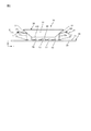
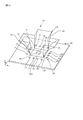
- FIG. 1 is a perspective view of the antenna device according to the first embodiment.
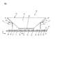
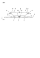
- FIG. 2 is a side view of the antenna device according to the first embodiment.
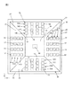
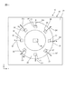
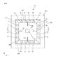
- FIG. 3 is a plan view of the antenna device according to the first embodiment.
- FIG. 4 is a circuit diagram of the communication device.
- FIG. 5 is a schematic view of a vehicle equipped with a communication device.
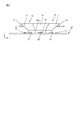
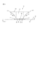
- FIG. 6 is a side view of the antenna device according to the second embodiment.
- FIG. 7 is a plan view of the antenna device according to the second embodiment.
- FIG. 8 is a side view of the antenna device according to the third embodiment.
- FIG. 9 is a plan view of the antenna device according to the third embodiment.
- FIG. 10 is a side view of the antenna device according to the fourth embodiment.
- FIG. 11 is a plan view of the antenna device according to the fourth embodiment.
- FIG. 12 is a perspective view of the antenna device according to the fifth embodiment.
- FIG. 13 is a side view of the antenna device according to the fifth embodiment.
- FIG. 14 is a plan view of the antenna device according to the fifth embodiment.
- FIG. 15 is a plan view of the antenna device according to the sixth embodiment.
- FIG. 16 is a cross-sectional view taken along the line AA of FIG.
- the antenna needs to be installed so that the beam faces the communication partner.
- the roof of a vehicle is generally a plate-like structure having a horizontal plane.
- the antenna device projects upward from the roof of the vehicle. Therefore, a protruding portion is generated on the roof of the vehicle, which affects the appearance design of the vehicle.
- the antenna characteristics are sacrificed, for example, a beam suitable for the communication partner cannot be obtained.
- the antenna device mounted on the moving body has a low degree of freedom in design.
- the present disclosure even if there are restrictions on the form or appearance design of the place where the antenna can be installed, it is possible to direct the beam to the communication partner, and it is possible to suppress a decrease in the degree of freedom in design.
- the antenna device includes an antenna mounted on a moving body and a reflector having a reflecting surface for changing the beam direction of the antenna.
- the reflector can change the beam direction of the antenna. Therefore, it is possible to direct the beam to the communication partner even if there are restrictions on the form or appearance design of the place where the antenna can be installed.
- the antenna includes one or a plurality of first antenna elements that generate a first beam
- the reflective surface comprises one or more second antenna elements that give rise to a second beam. It includes a first reflection region in which the first beam is directed in the first direction, and a second reflection region in which the second beam is directed in a second direction different from the first direction.
- the beam can be directed in a plurality of directions including the first direction and the second direction.
- the antenna device may be capable of directing the beam in other directions as well as in the first and second directions.
- the first antenna element and the second antenna element are preferably arranged so that the first beam and the second beam face the same direction between the antenna and the reflector. .. In this case, the antenna can be easily manufactured.
- the first antenna element and the second antenna element are preferably provided on the same base member. In this case, a configuration in which a plurality of antenna elements are integrated and arranged in the same base member can be obtained.
- the first antenna element and the second antenna element are preferably provided on the same surface of the base member. Antenna elements provided on the same surface are advantageous for obtaining a compact antenna.
- the first antenna element and the second antenna element are preferably provided on the same plane of the base member. In this case, a more compact antenna can be obtained.
- the first antenna element and the second antenna element are arranged between the antenna and the reflector so that the first beam and the second beam face upward, and the first direction and the second beam are directed upward.
- the second direction is preferably a direction inclined to the horizontal direction side rather than the upper side. In this case, even if the antenna element is arranged so that the beam faces upward, the beam can be directed to the communication partner in the direction inclined in the horizontal direction with respect to the upper side.
- the first direction and the second direction are preferably directions between the horizontal direction and the upper direction.
- the beam can be directed to a communication partner existing diagonally upward.
- the first direction and the second direction are preferably different directions in the horizontal plane.
- the beam can be directed in different directions in the horizontal plane.
- the first direction and the second direction are preferably the same direction on the vertical plane. In this case, the directions of the beams in the vertical plane can be aligned.
- the reflective surface preferably has a concave curved surface region. In this case, the gain can be increased.
- the reflecting surface preferably has a parabolic curved surface region.
- the parabolic curved surface region preferably has a parabolic cross-sectional shape on a plane orthogonal to the plane on which the antenna is provided, and a straight cross-sectional shape on a plane parallel to the plane on which the antenna is provided. In this case, the gain can be increased.
- the antenna and the reflector are provided on a base member, and the base member is provided with a wireless circuit connected to the antenna.
- the antenna device and the wireless circuit can be integrated.
- the reflector has an internal space and the wireless circuit is arranged in the internal space.
- the internal space of the reflector can be effectively used as the arrangement area of the wireless circuit.
- the communication device of the embodiment includes an antenna mounted on a moving body, a reflector having a reflecting surface for changing the beam direction of the antenna, and a wireless circuit connected to the antenna.
- FIGS. 1, 2 and 3 show the mobile antenna device 10 according to the first embodiment.
- the mobile antenna device 10 includes an antenna 50.
- the antenna 50 is mounted on a moving body such as a vehicle (vehicle).
- a vehicle is, for example, a car, train, ship, or flying object.
- the antenna 50 of the embodiment is a patch antenna provided on the substrate (base member) 20.
- the patch antenna has antenna elements (patch elements) 51, 52, 53, 54 formed on the substrate 20.
- the substrate 20 is a dielectric substrate.
- the antenna elements 51, 52, 53, 54 are formed on the upper surface 21 (first surface; flat surface) of the substrate 20.
- a conductor layer serving as a ground surface is formed on the lower surface 22 (second surface; flat surface) of the substrate 20.
- the substrate 20 of the patch antenna is not limited to the one-layer structure as shown in the figure, and may have a multi-layer structure of two or more layers.
- a substrate having a two-layer structure having a first dielectric layer and a second dielectric layer can be adopted.
- a ground is formed on the surface of the first dielectric layer opposite to the second dielectric layer, and between the first dielectric layer and the second dielectric layer.
- a patch element to be fed is formed, and a non-feeding patch element is formed on the surface of the second dielectric layer opposite to the first dielectric layer.
- the antenna 50 is not limited to the patch antenna, and may be, for example, a slot antenna.
- the left-right direction on the upper surface 21 of the substrate shown in FIGS. 2 and 3 is x
- the direction orthogonal to x on the upper surface 21 is y
- the direction orthogonal to the xy plane is z.
- the xy plane becomes, for example, a horizontal plane.
- the left side is referred to as the ⁇ x direction
- the right side is referred to as the + x direction.
- the lower portion is referred to as the ⁇ y direction
- the upper portion is referred to as the + y direction.
- the antenna 50 has a plurality of antenna element groups.
- the plurality of antenna element groups are, for example, four groups.
- the first group is composed of a plurality of (4) first antenna elements 51.
- the second group is composed of a plurality (4) second antenna elements 52.
- the third group is composed of a plurality of (4) third antenna elements 53.
- the fourth group is composed of a plurality (4) fourth antenna elements 54. That is, the antenna 50 of the embodiment has 16 antenna elements 51, 52, 53, 54.
- a plurality of (16) antenna elements 51, 52, 53, 54 are arranged in a rectangular circumferential shape so as to form four sides of the rectangle. That is, the first group of the first antenna elements 51 constitutes the first side of the rectangle. Further, the second group of the second antenna element 52 constitutes the second side which is the opposite side of the first side. Further, the third group of the third antenna element 53 constitutes the first side and the third side orthogonal to the second side, and the fourth group of the fourth antenna element 54 is the opposite side of the third side. It constitutes four sides.
- each of the antenna elements 51, 52, 53, 54 forms a beam facing upward Du (see FIG. 2).
- the moving body antenna device 10 includes a reflector 30.
- the reflector 30 is made of metal, for example, and reflects radio waves.
- the reflector 30 is provided on the upper surface 21 of the substrate 20.
- the reflector 30 is erected in a region (rectangular region) surrounded by a plurality of antenna elements 51, 52, 53, 54.
- the reflector 30 includes a base portion 30A attached to the substrate 20 and reflection surfaces (reflection regions) 31, 32, 33, 34 provided above the base portion 30A.
- the base portion 30A is configured as a rectangular frame.
- the reflecting surface has a plurality of reflecting regions 31, 32, 33, 34 extending diagonally upward from each of the four sides of the rectangular base portion 30A.
- the reflected regions 31, 32, 33, and 34 shown in the figure are planes, respectively, and are arranged so as to form four pyramidal surfaces in the square pyramid.
- the square weight stand here is an inverted square weight base in which the bottom surface having a small area is on the lower side and the bottom surface having a large area is on the upper side.
- the inside of the reflector 30 is hollow.
- the plurality of reflection regions 31, 32, 33, 34 include the first reflection region (first reflection surface) 31. As shown in FIG. 2, the first reflection region 31 is located above the first antenna element 51. The first reflection region 31 directs the first beam toward the upper Du generated from the first antenna element 51 toward the first direction D1.
- the first direction D1 is substantially horizontal (in FIG. 2, the elevation angle with respect to the horizontal plane H is 10 °) as shown in FIG. 2, and is in the ⁇ x direction as shown in FIG.
- the plurality of reflection regions 31, 32, 33, 34 include the second reflection region (second reflection surface) 32.
- the second reflection region 32 is located above the second antenna element 52.
- the second reflection region 32 directs the upper Du-oriented second beam generated from the second antenna element 52 in the second direction D2.
- the second direction D2 is substantially horizontal (elevation angle is 10 °) as shown in FIG. 2, and is in the + x direction as shown in FIG.
- the plurality of reflection regions 31, 32, 33, 34 include a third reflection region (third reflection surface) 33.
- the third reflection region 33 is located above the third antenna element 53.
- the third reflection region 33 directs the upward Du-oriented third beam generated from the third antenna element 53 toward the third direction D3.
- the third direction D3 is substantially horizontal (elevation angle is 10 °) and is the ⁇ y direction as shown in FIG.
- the plurality of reflection regions 31, 32, 33, 34 include the fourth reflection region (fourth reflection surface) 34.
- the fourth reflection region 34 is located above the fourth antenna element 54.
- the fourth reflection region 34 directs the fourth beam in the upward Du direction generated from the fourth antenna element 54 in the fourth direction D4.
- the fourth direction D4 is substantially horizontal (elevation angle is 10 °) and is in the + y direction as shown in FIG.
- the reflector 30 directs the first beam toward the first direction D1, the second beam toward the second direction D2, the third beam toward the third direction D3, and the fourth beam toward the fourth direction.
- Each of the directions D1, D2, D3, and D4 is a direction inclined toward the horizontal H side with respect to the upper Du. Therefore, even if the antenna 50 itself is arranged so that the beams generated from the plurality of antenna elements 51, 52, 54, 54 are all directed to the upper Du in the same direction, the reflector 30 allows the upper Du to be arranged. A beam oriented in a direction inclined toward the H side in the horizontal direction can be obtained. Therefore, beam directivity suitable for communication with a communication partner in a direction other than the upper Du can be obtained.
- the reflector 30 can obtain beams pointing in each of the plurality of directions D1, D2, D3, D4, the plurality of antenna elements 51, 52, 54, 54 all face the same direction Du.
- the arrangement may be such that a beam is generated. That is, the plurality of antenna elements 51, 52, 54, 54 are arranged so that each beam faces Du in the same direction between the antenna 50 and the reflector 30. Therefore, in the embodiment, a configuration in which a plurality of antenna elements 51, 52, 53, 54 for different directions D1, D2, D3, and D4 are integrated and arranged on the same base member (board) 20 is realized. ing.
- the plurality of antenna elements 51, 52, 53, 54 for different directions D1, D2, D3, D4 are provided on the same surface as the upper surface 21 of the substrate.
- the antenna elements 51, 52, 53, 54 provided on the same surface are advantageous for obtaining a compact antenna 50.
- the substrate upper surface 21 is a flat surface, it has been realized that a plurality of antenna elements 51, 52, 53, 54 for different directions D1, D2, D3, D4 are provided on the same plane as the substrate upper surface 21. There is.
- the antenna elements 51, 52, 53, 54 provided on the same plane are advantageous for obtaining a more compact antenna 50.
- the first direction D1, the second direction D2, the third direction D3, and the fourth direction D4 are all different directions in the horizontal plane H (xy plane). Therefore, the antenna device 10 as a whole can secure a wide directivity in the horizontal plane.
- the first direction D1, the second direction D2, the third direction D3, and the fourth direction D4 are each reflected so that the angle (for example, elevation angle) ⁇ with respect to the horizontal plane H (xy plane) is equivalent.
- the tilt angles of the regions 31, 32, 33, and 34 are set to be equivalent. Therefore, the beam angle ⁇ with respect to the horizontal plane H can be made uniform regardless of the directions D1, D2, D3, and D4 in the horizontal plane.
- “angles are equivalent” is not limited to exactly the same angle, but includes substantially the same angle.
- the substantially same angle means the same angle that can be identified as a beam angle.
- the difference in angle caused by manufacturing error does not prevent the identification of beam angles.
- the difference in the angle allowed by the specifications of the antenna does not hinder the identification of the beam angle. That is, it can be said that the angles are equivalent within a predetermined angle range allowed from some viewpoint.
- the reflector 30 when configured as an integrally molded product, it becomes easy to align the angles ⁇ with respect to the horizontal plane H in each direction D1, D2, D3, D4.
- the antenna device 10 of the embodiment is suitable for communication with a communication partner existing diagonally upward.
- the communication partner that exists diagonally upward is, for example, a radio base station installed at a high place such as a rooftop of a building or a steel tower.
- the reflector 30 of the embodiment is hollow. That is, the reflector 30 has an internal space surrounded by a base 30A and reflection regions 31, 32, 33, 34.
- the reflector 30 provided on the upper surface 21 of the substrate 20 divides the upper surface 21 into a reflector outer region 25 and a reflector inner region 26.
- the reflector outer region 25 is an antenna element arrangement region in which a plurality of antenna elements 51, 52, 53, 54 are arranged.
- the reflector internal region 26 is a circuit arrangement region in which the wireless circuit 60 connected to the antenna 50 is arranged.
- An element (integrated circuit, etc.) of the wireless circuit 60 including a transmitter / receiver is provided in the internal region 26 used as the circuit arrangement region of the substrate 20. That is, the element of the wireless circuit 60 is provided inside the reflector 30. By providing the element of the wireless circuit 60 inside the reflector 30, the space of the substrate 20 can be effectively utilized. Further, since the inside of the reflector 30 is not easily affected by radio waves, it is suitable as an arrangement space for the wireless circuit 60.
- FIG. 4 shows a communication device 100 including an antenna device 10 including a plurality of antenna elements 51, 52, 53, 54, and a wireless circuit 60 connected to the antenna device 10.
- the wireless circuit 60 is provided in the antenna device 10.
- the wireless circuit 60 includes a four-partition phase device 70 connected to the four first antenna elements 51, a four-partition phase device 70 connected to the four second antenna elements 52, and four third antenna elements. It includes a 4-partition phase device 70 connected to 53 and a 4-partition phase device 70 connected to four 4th antenna elements 54.
- the plurality of 4-distributed phasers 70 are connected to the transmitter / receiver 90 via the selector 80.
- the 4-distributor phase device 70 includes a 4-distributor 72 and a phase device 71 provided between the 4-distributor 72 and the antenna element.
- the phase device 71 enables, for example, beam steering (beam forming) that changes the direction of the beam in a horizontal plane.
- the selector 80 connects the transmitter / receiver 90 to any one of a plurality of 4-distributed phase units 70.
- the antenna element used for communication is an antenna element connected to the transmitter / receiver 90 via the selector 80.
- the antenna element (active antenna element) used for communication is switched. Therefore, even if the direction of the moving body changes, the beam can be formed in the direction in which the communication partner exists. For example, even if the relative positional relationship between the moving body and the communication partner changes with the movement of the moving body, the state in which the beam is directed toward the communication partner can be maintained.
- FIG. 5 shows an example in which the communication device 100 is mounted on the vehicle 200.
- the communication device 100 is configured as a mobile station that communicates with the radio base station 300.
- the communication device 100 is mounted on the roof 210.
- the roof 210 is a plate-shaped structure.
- the roof 210 is formed with a recess 220 for accommodating the communication device 100.
- the communication device 100 is arranged in the recess 220.
- the communication device 100 is installed on the roof 210 so that the substrate 20 is horizontal and the upper surface 21 of the substrate faces upward.
- the reflector 30 forms an obliquely upward beam, so that communication with a communication partner such as a base station 300 installed obliquely upward is performed.
- the antenna device 10 of the present embodiment is lowered by the reflector 30, it does not protrude from the roof 210 even if it is installed on the roof 210, or even if it protrudes, it can be slightly projected. The influence of can be suppressed.
- FIG 6 and 7 show the mobile antenna device 10 according to the second embodiment.
- the points not particularly described in the second and subsequent embodiments are the same as those in the first embodiment.
- each of the plurality of antenna element groups has a plurality of rows of antenna elements.
- each of the plurality of antenna element groups is composed of a row of antenna elements. That is, in the first embodiment, the first group consists of four first antenna elements 51 arranged in a row. Similarly, in the second group, four second antenna elements 52 are arranged in one row, and in the third group, four third antenna elements 53 are arranged in one row, and the fourth group. Is composed of four fourth antenna elements 54 arranged in a row.
- the longitudinal direction of the row of each group is a direction orthogonal to the direction of the beam generated by the antenna element belonging to each group.
- the longitudinal direction of the row of the first antenna elements 51 is the y direction orthogonal to the first direction D1 ( ⁇ x) to which the first beam faces.
- the first group of the first antenna elements 51 has a plurality of (4) rows 51A, 51B, 51C, 51D.
- Each row 51A, 51B, 51C, 51D has four antenna elements 51, respectively.
- the arrangement direction of the plurality of rows 51A, 51B, 51C, 51D is the direction (x direction) in which the first direction D1 to which the first beam faces is projected onto the horizontal plane (xy plane).
- the second group of the second antenna elements 52 has a plurality of (4) rows 52A, 52B, 52C, 52D.
- Each row 52A, 52B, 52C, 52D has four antenna elements 52, respectively.
- the arrangement direction of the plurality of rows 52A, 52B, 52C, 52D is the direction (x direction) in which the second direction D2 to which the second beam faces is projected on the horizontal plane (xy plane).
- the third group of the third antenna element 53 has a plurality of (4) rows 53A, 53B, 53C, 53D.
- Each row 53A, 53B, 53C, 53D has four antenna elements 53, respectively.
- the arrangement direction of the plurality of rows 53A, 53B, 53C, 53D is the direction (y direction) in which the third direction D3 to which the third beam faces is projected on the horizontal plane (xy plane).
- the fourth group of the fourth antenna elements 54 has a plurality of (4) rows 54A, 54B, 54C, 54D. Each row 54A, 54B, 54C, 54D has four antenna elements 54, respectively.
- the arrangement direction of the plurality of rows 54A, 54B, 54C, 54D is the direction (y direction) in which the fourth direction D4 to which the fourth beam faces is projected on the horizontal plane (xy plane).
- the gain can be increased. Further, since the number of antenna elements is large, the beam becomes sharp and the beam width becomes narrow. Therefore, the effect of beamforming becomes greater. Moreover, by adjusting the phase for each of a plurality of rows of antenna elements, the direction of the beam toward the communication partner such as the base station 300 can be changed in the vertical plane.
- the antenna 50 has eight antenna element groups.
- the first group consists of one first antenna element 51.
- the second group consists of one second antenna element 52.
- the third group consists of one third antenna element 53.
- the fourth group consists of one fourth antenna element 54.
- the fifth group consists of one fifth antenna element 55.
- the sixth group consists of one sixth antenna element 56.
- the seventh group consists of one seventh antenna element 57.
- the eighth group consists of one eighth antenna element 58. That is, the antenna 50 of the third embodiment has eight antenna elements 51, 52, 53, 54, 55, 56, 57, 58.
- the eight antenna elements 51, 52, 53, 54, 55, 56, 57, 58 are arranged in a polygonal circumferential shape (octagonal circumferential shape). That is, the first group of the first antenna elements 51 constitutes the first side of the octagon. Further, the second group of the second antenna element 52 constitutes the second side which is the opposite side of the first side. Further, the third group of the third antenna element 53 constitutes the third side, and the fourth group of the fourth antenna element 54 constitutes the fourth side which is the opposite side of the third side. The fifth group of the fifth antenna element 55 constitutes the fifth side, and the sixth group of the sixth antenna element 56 constitutes the sixth side which is the opposite side of the fifth side. The seventh group of the seventh antenna element 57 constitutes the seventh side, and the eighth group of the eighth antenna element 58 constitutes the eighth side, which is the opposite side of the seventh side.
- the reflector 30 includes an octagonal base portion 30A and reflecting surfaces 31, 32, 33, 34, 35, 36, 37, 38.
- the reflecting surface has a plurality of reflecting regions 31, 32, 33, 34, 35, 36, 37, 38 extending diagonally upward from each of the eight sides of the octagonal base 30A.
- the illustrated reflection regions 31, 32, 33, 34, 35, 36, 37, 38 are arranged to form eight pyramidal surfaces in the octagonal weight stand.
- the octagonal weight stand here is an inverted octagonal weight stand in which the bottom surface having a small area is on the lower side and the bottom surface having a large area is on the upper side.
- the inside of the reflector 30 is hollow.
- the plurality of reflection regions 31, 32, 33, 34, 35, 36, 37, 38 are the first reflection region (first reflection surface) 31, the second reflection region (second reflection surface) 32, and the third reflection region (3rd reflection region).
- 3rd reflection surface) 33, 4th reflection region (4th reflection surface) 34, 5th reflection region (5th reflection surface) 35, 6th reflection region (6th reflection surface) 36, 7th reflection region (7th reflection surface) Includes a reflective surface) 37 and an eighth reflective region (eighth reflective surface) 38.
- the first reflection region 31 is located above the first antenna element 51 and directs the beam of the first antenna element 51 in the first direction D1.
- the second reflection region 32 is located above the second antenna element 52 and directs the beam of the second antenna element 52 in the second direction D2.
- the third reflection region 33 is located above the third antenna element 53 and directs the beam of the third antenna element 53 in the third direction D3.
- the fourth reflection region 34 is located above the fourth antenna element 54 and directs the beam of the fourth antenna element 54 in the fourth direction D4.
- the fifth reflection region 35 is located above the fifth antenna element 55 and directs the beam of the fifth antenna element 55 in the fifth direction D5.
- the sixth reflection region 36 is located above the sixth antenna element 56 and directs the beam of the sixth antenna element 56 in the sixth direction D6.
- the seventh reflection region 37 is located above the seventh antenna element 57 and directs the beam of the seventh antenna element 57 in the seventh direction D7.
- the eighth reflection region 38 is located above the eighth antenna element 58 and directs the beam of the eighth antenna element 58 in the eighth direction D8.
- a selector in which the 4-port switching selector 80 shown in FIG. 4 is switched to 8-port switching is used.
- the 8-port switching selector connects the transmitter / receiver 90 to any one of the eight antenna elements 51, 52, 53, 54, 55, 56, 57, 58.
- the beam can be directed to any one of the eight directions D1, D2, D3, D4, D5, D6, D7, and D8, and the directivity can be efficiently ensured in all directions.
- the beam is configured to be directed in more directions than in the first embodiment, directivity in all directions in the horizontal plane is ensured without beamforming in the horizontal plane. Is easy.
- the antenna 50 of the fourth embodiment is the same as the antenna 50 of the third embodiment.
- the reflector 30 of the fourth embodiment includes a cylindrical base portion 30A and reflecting surfaces 31, 32, 33, 34, 35, 36, 37, 38.
- the reflective surface constitutes the pyramidal surface of the inverted pedestal.
- the reflector 30 has eight reflection regions 31, 32, 33, 34, 35, 36, 37, 38, but each reflection region 31, 32. , 33, 34, 35, 36, 37, 38, there is no clear boundary.
- the first reflection region 31 is a region located above the first antenna element 51, and directs the beam of the first antenna element 51 in the first direction D1.
- the second reflection region 32 is a region located above the second antenna element 52, and directs the beam of the second antenna element 52 in the second direction D2.
- the third reflection region 33 is a region located above the third antenna element 53, and directs the beam of the third antenna element 53 in the third direction D3.
- the fourth reflection region 34 is a region located above the fourth antenna element 54, and directs the beam of the fourth antenna element 54 in the fourth direction D4.
- the fifth reflection region 35 is a region located above the fifth antenna element 55, and directs the beam of the fifth antenna element 55 in the fifth direction D5.
- the sixth reflection region 36 is a region located above the sixth antenna element 56, and directs the beam of the sixth antenna element 56 in the sixth direction D6.
- the seventh reflection region 37 is a region located above the seventh antenna element 57, and directs the beam of the seventh antenna element 57 in the seventh direction D7.
- the eighth reflection region 38 is a region located above the eighth antenna element 58, and directs the beam of the eighth antenna element 58 in the eighth direction D8.
- the antenna element may be arranged at any position below the reflecting surface, which is advantageous when many antenna elements are to be installed.
- the antenna 50 of the fifth embodiment is the same as the antenna 50 of the first embodiment.
- the reflector 130 of the fifth embodiment also has four reflection regions 131, 132, 133, 134 like the reflector 30 of the first embodiment.
- the reflection regions 31, 32, 33, 34 of the first embodiment are flat surfaces
- the reflection regions 131, 132, 133, 134 of the fifth embodiment are concave curved surfaces (concave curved surface regions). , More specifically, it is a parabolic curved surface (parabolic curved surface region).
- the concave curved surface of the embodiment does not have to be a flat surface, and its shape is not particularly limited.
- the parabolic curved surface of the embodiment has a parabolic cross-sectional shape in a plane orthogonal to the plane 21 (xy plane) on which the antenna 50 is provided. Further, the parabolic curved surface of the embodiment has a straight cross-sectional shape on a plane (xy plane) parallel to the plane 21.
- the extending direction of the straight line is preferably parallel to the arrangement direction of the plurality of antenna elements whose beam direction is changed by the parabolic curved surface.
- the plane orthogonal to the plane 21 (xy plane) is the yz plane or the zx plane.
- the cross-sectional shape in the zx plane which is an orthogonal plane is a parabola
- the cross-sectional shape in the xy plane which is a plane parallel to the plane 21 is a straight line.
- the straight line of the cross-sectional shape of the reflection regions 131 and 132 is parallel to the arrangement direction (y direction) of the plurality of antenna elements 51 and 52.
- the cross-sectional shape in the yz plane which is an orthogonal plane is a parabola
- the cross-sectional shape in the xy plane which is a plane parallel to the plane 21 is a straight line.
- the straight line of the cross-sectional shape of the reflection regions 133 and 134 is parallel to the arrangement direction (x direction) of the plurality of antenna elements 53 and 54.
- the reflection regions 131, 132, 133, and 134 have a straight line as the cross-sectional shape in the horizontal plane xy plane, the change in the characteristics in the horizontal plane can be suppressed even if the beam direction is changed.
- the beam can be concentrated in the directions D1, D2, D3, and D4 where the beam is to be directed, and the gain can be increased.
- the reflection regions 131, 132, 133, and 134 are parabolic surfaces, the beam can be more concentrated in the directions D1, D2, D3, and D4 in which the beam is to be directed, and the gain can be further increased.
- the antenna elements 51, 52, 53, 54 are arranged at the focal position of the parabola of the parabolic curved surface or near the focal position. That is, the first antenna element 51 is arranged at or near the focal position of the first reflection region 131, which is a parabolic curved surface.
- the second antenna element 52 is arranged at or near the focal position of the second reflection region 132, which is a parabolic curved surface.
- the third antenna element 53 is arranged at or near the focal position of the third reflection region 133, which is a parabolic curved surface.
- the fourth antenna element 54 is arranged at or near the focal position of the fourth reflection region 134, which is a parabolic curved surface.
- the antenna 50 of the sixth embodiment is the same as the antenna 50 of the first embodiment.
- the reflector 230 of the sixth embodiment is erected outside the region (rectangular region) surrounded by the plurality of antenna elements 51, 52, 53, 54. In other words, the plurality of antenna elements 51, 52, 53, 54 are arranged in the inner space of the reflector 230.
- the reflector 230 includes a base 230A arranged around the substrate 20 forming the antenna 50, and reflection surfaces (reflection regions) 231, 232, 233, 234 provided above the base 230A.
- the base 230A is configured as a rectangular frame surrounding the substrate 20 and has an opening 236 at the top.
- the reflecting surface has a plurality of reflecting regions 231,232, 233, 234 extending diagonally upward from each of the four sides of the rectangular base 230A.
- the illustrated reflection regions 231, 232, 233, and 234 are planes, respectively, and are arranged so as to form four pyramidal surfaces in the square pyramid. In the square weight stand here, the bottom surface having a large area is on the lower side, and the bottom surface having a small area is on the upper side.
- the plurality of reflection regions 231, 232, 233, and 234 include the first reflection region (first reflection surface) 231. As shown in FIG. 16, the first reflection region 231 is inclined inward so as to be located above the first antenna element 51. The first reflection region 231 directs the upward Du-oriented first beam generated from the first antenna element 51 toward the first direction D1. The first beam goes out of the reflector 230 through the opening 236.
- the first direction D1 is the + x direction as shown in FIG.
- the plurality of reflection regions 231, 232, 233, 234 include a second reflection region (second reflection surface) 232.
- the second reflection region 232 is located above the second antenna element 52.
- the second reflection region 232 directs the upper Du-oriented second beam generated from the second antenna element 52 in the second direction D2.
- the second beam goes out of the reflector 230 through the opening 236.
- the second direction D2 is the ⁇ x direction as shown in FIG.
- the plurality of reflection regions 231, 232, 233, 234 include a third reflection region (third reflection surface) 233.
- the third reflection region 233 is located above the third antenna element 53.
- the third reflection region 233 directs the upward Du-oriented third beam generated from the third antenna element 53 toward the third direction D3.
- the third beam goes out of the reflector 230 through the opening 236.
- the third direction D3 is the + y direction as shown in FIG.
- the plurality of reflection regions 231, 232, 233, 234 include a fourth reflection region (fourth reflection surface) 234.
- the fourth reflection region 234 is located above the fourth antenna element 54.
- the fourth reflection region 234 directs the fourth beam in the upward Du direction generated from the fourth antenna element 54 in the fourth direction D4.
- the fourth beam goes out of the reflector 230 through the opening 236.
- the fourth direction D4 is the ⁇ y direction as shown in FIG.
- the reflector 230 can obtain beams pointing in each of the plurality of directions D1, D2, D3, and D4. Further, in the sixth embodiment, even if the noise generation source (external device or the like) 400 exists in the outer space of the reflector 230, it is possible to prevent the noise generation source 400 from interfering with the antenna 50. That is, the reflector 230 not only reflects the beam, but also functions as a shield against noise. Therefore, the noise resistance is improved.
- the element (integrated circuit, etc.) of the wireless circuit 60 may be provided on the upper surface 21 of the substrate 20, but the substrate is like the wireless circuit 60 shown by the dotted line in FIG. It may be provided on the lower surface 22 of 20. In this case, interference between the wireless circuit 60 and the antenna 50 can be prevented.
- Antenna device 20 Substrate 21: Top surface 22: Bottom surface 25: Reflector outer region 26: Reflector internal region 30: Reflector 30A: Base 31: First reflection region 32: Second reflection region 33: Third reflection region 34: 4th reflection area 35: 5th reflection area 36: 6th reflection area 37: 7th reflection area 38: 8th reflection area 50: Antenna 51: 1st antenna element 51A: Row 51B: Row 51C: Row 51D: Row 52: Second antenna element 52A: Row 52B: Row 52C: Row 52D: Row 53: Third antenna element 53A: Row 53B: Row 53C: Row 53D: Row 54: Fourth antenna element 54A: Row 54B: Row 54C : Row 55: 5th antenna element 56: 6th antenna element 57: 7th antenna element 58: 8th antenna element 60: Radio circuit 70: 4 distribution phase device 71: Phase device 72: 4 distributor 80: Selector 90: Transmitter / receiver 100: Communication device 130: Reflector 131: Reflection area 132: Reflection area 132:
Landscapes
- Engineering & Computer Science (AREA)
- Remote Sensing (AREA)
- Aerials With Secondary Devices (AREA)
- Variable-Direction Aerials And Aerial Arrays (AREA)
- Support Of Aerials (AREA)
Abstract
開示の移動体用アンテナ装置は、移動体に搭載されるアンテナと、前記アンテナのビーム方向を変える反射面を有する反射器と、を備える。
Description
本開示は、移動体用アンテナ装置及び通信装置に関する。本出願は、2019年3月18日出願の日本出願第2019-050392号に基づく優先権を主張し、前記日本出願に記載された全ての記載内容を援用するものである。
特許文献1は、車両に搭載されるアンテナ装置を開示している。
本開示のある側面は、アンテナ装置である。開示のアンテナ装置は、移動体に搭載されるアンテナと、前記アンテナのビーム方向を変える反射面を有する反射器と、を備える。
本開示の他の側面は、通信装置である。開示の通信装置は、移動体に搭載されるアンテナと、前記アンテナのビーム方向を変える反射面を有する反射器と、前記アンテナに接続される無線回路と、を備える。
[本開示が解決しようとする課題]
アンテナは、通信相手にビームが向くように設置される必要がある。しかし、車両などの移動体においては、設置可能な箇所の形態又は外観デザイン上の制約があり、通信相手にビームが向くようにアンテナを設置することが困難なことがある。
例えば、車両のルーフは、一般に、水平面を有する板状の構造体である。このようなルーフに搭載されたアンテナによって、ほぼ水平方向のビームを得るには、ビームを形成するアンテナ面を垂直に立てる必要がある。この場合、車両のルーフからアンテナ装置が上方に突出する。したがって、車両のルーフに突出した部位が生じ、車両の外観デザインに影響を与える。一方、車両の外観デザインへの影響を抑えようとすると、通信相手に向くビームが得られないなどアンテナ特性が犠牲になる。このように、移動体に搭載されるアンテナ装置は設計の自由度が低い。
したがって、アンテナを設置可能な箇所の形態又は外観デザイン上の制約があっても、通信相手にビームを向けることを可能とし、設計の自由度低下を抑制することが望まれる。
本開示によれば、アンテナを設置可能な箇所の形態又は外観デザイン上の制約があっても、通信相手にビームを向けることを可能とし、設計の自由度低下を抑制することができる。
[本開示の実施形態の説明]
(1)実施形態に係るアンテナ装置は、移動体に搭載されるアンテナと、前記アンテナのビーム方向を変える反射面を有する反射器と、を備える。反射器によって、アンテナのビーム方向を変えることができる。このため、アンテナを設置可能な箇所の形態又は外観デザイン上の制約があっても、通信相手にビームを向けることが可能である。
(2)前記アンテナは、第1ビームを生じさせる1又は複数の第1アンテナ素子と、
第2ビームを生じさせる1又は複数の第2アンテナ素子と、を含み、前記反射面は、
前記第1ビームを、第1方向に向ける第1反射領域と、前記第2ビームを、前記第1方向とは異なる第2方向に向ける第2反射領域と、を含む。この場合、第1方向及び第2方向を含む複数の方向にビームを向けることができる。なお、アンテナ装置は、第1方向及び第2方向のほか、他の方向にもビームを向けることができてもよい。
第2ビームを生じさせる1又は複数の第2アンテナ素子と、を含み、前記反射面は、
前記第1ビームを、第1方向に向ける第1反射領域と、前記第2ビームを、前記第1方向とは異なる第2方向に向ける第2反射領域と、を含む。この場合、第1方向及び第2方向を含む複数の方向にビームを向けることができる。なお、アンテナ装置は、第1方向及び第2方向のほか、他の方向にもビームを向けることができてもよい。
(3)前記第1アンテナ素子及び前記第2アンテナ素子は、前記第1ビーム及び前記第2ビームが前記アンテナと前記反射器との間において同一方向を向くように、配置されているのが好ましい。この場合、アンテナの製作が容易となる。
(4)前記第1アンテナ素子及び前記第2アンテナ素子は、同一のべ―ス部材に設けられているのが好ましい。この場合、複数のアンテナ素子を同一のベース部材に統合して配置した構成が得られる。
(5)前記第1アンテナ素子及び前記第2アンテナ素子は、前記ベース部材の同一面に設けられているのが好ましい。同一面に設けられたアンテナ素子は、コンパクトなアンテナを得るために有利である。
(6)前記第1アンテナ素子及び前記第2アンテナ素子は、前記ベース部材の同一平面に設けられているのが好ましい。この場合、よりコンパクトなアンテナが得られる。
(7)前記第1アンテナ素子及び前記第2アンテナ素子は、前記アンテナと前記反射器との間において、前記第1ビーム及び前記第2ビームが上方に向くよう配置され、前記第1方向及び前記第2方向は、前記上方よりも水平方向側へ傾いた方向であるのが好ましい。この場合、ビームが上方に向くアンテナ素子配置をしても、上方よりも水平方向側へ傾いた方向にある通信相手にビームを向けることができる。
(8)前記第1方向及び第2方向は、前記水平方向と前記上方との間の方向であるのが好ましい。この場合、斜め上方に存在する通信相手にビームを向けることができる。
(9)前記第1方向及び第2方向は、水平面において異なる方向であるのが好ましい。この場合、水平面において異なる方向にビームを向けることができる。
(10)前記第1方向及び第2方向は、垂直面において同一の方向であるのが好ましい。この場合、垂直面におけるビームの方向を揃えることができる。
(11)前記反射面は、凹曲面領域を有するのが好ましい。この場合、利得を大きくすることができる。
(12)前記反射面は、放物曲面領域を有するのが好ましい。前記放物曲面領域は、前記アンテナが設けられた面に対する直交面における断面形状が放物線であり、前記アンテナが設けられた前記面に平行な面における断面形状が直線であるのが好ましい。この場合、利得をより大きくすることができる。
(13)前記アンテナ及び前記反射器は、ベース部材に設けられ、前記ベース部材には、前記アンテナに接続される無線回路が設けられているのが好ましい。この場合、アンテナ装置と無線回路とを一体的にすることができる。
(14)前記反射器は、内部空間を持ち、前記無線回路は、前記内部空間内に配置されているのが好ましい。この場合、反射器の内部空間を無線回路の配置領域として有効活用できる。
(15)実施形態の通信装置は、移動体に搭載されるアンテナと、前記アンテナのビーム方向を変える反射面を有する反射器と、前記アンテナに接続される無線回路と、を備える。
[本開示の実施形態の詳細]
[第1実施形態]
図1,図2,図3は、第1実施形態に係る移動体用アンテナ装置10を示している。移動体用アンテナ装置10は、アンテナ50を備える。アンテナ50は、車両(ビークル:vehicle)などの移動体に搭載される。ビークルは、例えば、自動車、列車、船舶、又は飛行体である。実施形態のアンテナ50は、基板(ベース部材)20上に設けられたパッチアンテナである。パッチアンテナは、基板20に形成されたアンテナ素子(パッチ素子)51,52,53,54を有する。基板20は、誘電体基板である。アンテナ素子51,52,53,54は、基板20の上面21(第1面;平面)に形成されている。基板20の下面22(第2面;平面)には、グランド面となる導体層が形成されている。パッチアンテナの基板20は、図示のような1層構造に限られず、2層以上の多層構造であってもよい。例えば、第1誘電体層及び第2誘電体層を有する2層構造の基板を採用できる。2層構造の基板が用いられる場合、例えば、第2誘電体層とは反対側の第1誘電体層の面にグランドが形成され、第1誘電体層と第2誘電体層との間に給電されるパッチ素子が形成され、第1誘電体層とは反対側の第2誘電体層の面に無給電パッチ素子が形成される。なお、アンテナ50は、パッチアンテナに限られるものではなく、例えば、スロットアンテナであってもよい。
以下の説明では、図2,図3に示す基板上面21における左右方向をxとし、上面21においてxと直交する方向をyとし、xy平面と直交する方向をzとする。車両などの移動体に搭載された状態において、xy平面は、例えば、水平面となる。また、図3において、左方を、-x方向といい、右方を+x方向という。また、図3において、下方を-y方向といい、上方を+y方向という。
第1実施形態において、アンテナ50は、複数のアンテナ素子グループを有する。複数のアンテナ素子グループは、例えば、4つのグループである。第1グループは、複数(4個)の第1アンテナ素子51からなる。第2グループは、複数(4個)の第2アンテナ素子52からなる。第3グループは、複数(4個)の第3アンテナ素子53からなる。第4グループは、複数(4個)の第4アンテナ素子54からなる。つまり、実施形態のアンテナ50は、16個のアンテナ素子51,52,53,54を有する。
複数(16個)のアンテナ素子51,52,53,54は、矩形の4辺を構成するよう矩形周状に配置されている。つまり、第1アンテナ素子51の第1グループが、矩形の第1辺を構成する。また、第2アンテナ素子52の第2グループが、第1辺の対向辺である第2辺を構成する。さらに、第3アンテナ素子53の第3グループが、第1辺及び第2辺に直交する第3辺を構成し、第4アンテナ素子54の第4グループが、第3辺の対向辺である第4辺を構成する。
アンテナ素子51,52,53,54は、水平面である基板上面21に設けられているため、各アンテナ素子51,52,53,54は、上方Duに向くビームを形成する(図2参照)。
移動体用アンテナ装置10は、反射器30を備える。反射器30は、例えば、金属性であり、電波を反射する。反射器30は、基板20の上面21に設けられている。反射器30は、複数のアンテナ素子51,52,53,54で囲まれた領域(矩形領域)内において立設されている。
反射器30は、基板20に取り付けられる基部30Aと、基部30Aの上方に設けられた反射面(反射領域)31,32,33,34を備える。基部30Aは、矩形状の枠体として構成されている。反射面は、矩形状の基部30Aの4辺それぞれから、斜め上方へ延設された複数の反射領域31,32,33,34を有する。図示の反射領域31,32,33,34は、それぞれ平面であり、四角錘台における4つの錘体面を構成するよう配置されている。なお、ここでの四角錘台は、面積の小さい底面が下側にあり、面積の大きい底面が上側にある逆四角錘台である。なお、反射器30の内部は、中空である。
複数の反射領域31,32,33,34は、第1反射領域(第1反射面)31を含む。図2に示すように、第1反射領域31は、第1アンテナ素子51の上方に位置する。第1反射領域31は、第1アンテナ素子51から生じた上方Du向きの第1ビームを、第1方向D1へ向ける。第1方向D1は、図2に示すように、ほぼ水平(図2では、水平面Hに対する仰角が10°)であって、図3に示すように、-x方向である。
複数の反射領域31,32,33,34は、第2反射領域(第2反射面)32を含む。第2反射領域32は、第2アンテナ素子52の上方に位置する。第2反射領域32は、第2アンテナ素子52から生じた上方Du向きの第2ビームを、第2方向D2へ向ける。第2方向D2は、図2に示すように、ほぼ水平(仰角が10°)であって、図3に示すように、+x方向である。
複数の反射領域31,32,33,34は、第3反射領域(第3反射面)33を含む。第3反射領域33は、第3アンテナ素子53の上方に位置する。第3反射領域33は、第3アンテナ素子53から生じた上方Du向きの第3ビームを、第3方向D3へ向ける。第3方向D3は、ほぼ水平(仰角が10°)であって、図3に示すように、-y方向である。
複数の反射領域31,32,33,34は、第4反射領域(第4反射面)34を含む。第4反射領域34は、第4アンテナ素子54の上方に位置する。第4反射領域34は、第4アンテナ素子54から生じた上方Du向きの第4ビームを、第4方向D4へ向ける。第4方向D4は、ほぼ水平(仰角が10°)であって、図3に示すように、+y方向である。
以上のように、反射器30は、第1ビームを第1方向D1に向け、第2ビームを第2方向D2に向け、第3ビームを第3方向D3に向け、第4ビームを第4方向D4に向ける。各方向D1,D2,D3,D4は、それぞれ、上方Duよりも水平方向H側へ傾いた方向である。したがって、アンテナ50自体の配置は、複数のアンテナ素子51,52,54,54から生じたビームが全て同一方向である上方Duに向くような配置であっても、反射器30により、上方Duよりも水平方向H側へ傾いた方向に向くビームが得られる。したがって、上方Du以外の方向にある通信相手との通信に適したビーム指向性が得られる。
また、実施形態においては、反射器30によって複数の方向D1,D2,D3,D4それぞれを向くビームが得られるため、複数のアンテナ素子51,52,54,54は、全て同一の方向Duへ向くビームを生じさせる配置でよい。つまり、複数のアンテナ素子51,52,54,54は、各ビームが、アンテナ50と反射器30との間において、同一方向Duを向くように配置されている。したがって、実施形態においては、異なる方向D1,D2,D3,D4のための複数のアンテナ素子51,52,53,54を同一のベース部材(基板)20に統合して配置された構成が実現されている。
特に、実施形態においては、異なる方向D1,D2,D3,D4のための複数のアンテナ素子51,52,53,54は、基板上面21という同一面に設けることが実現されている。同一面に設けられたアンテナ素子51,52,53,54は、コンパクトなアンテナ50を得るために有利である。
しかも、基板上面21は、平面であるため、異なる方向D1,D2,D3,D4のための複数のアンテナ素子51,52,53,54を、基板上面21という同一平面に設けることが実現されている。同一平面に設けられたアンテナ素子51,52,53,54は、よりコンパクトなアンテナ50を得るために有利である。
実施形態において、第1方向D1、第2方向D2、第3方向D3、第4方向D4は、水平面H(xy平面)において全て異なる方向である。したがって、アンテナ装置10全体として、水平面における広い指向性を確保することができる。
また、実施形態において、第1方向D1、第2方向D2、第3方向D3、第4方向D4は、水平面H(xy平面)に対する角度(例えば、仰角)θが、等価になるように各反射領域31,32,33,34の傾斜角度が等価に設定されている。したがって、水平面における方向D1,D2,D3,D4にかかわらず、水平面Hに対するビーム角θを揃えることができる。ここで、「角度が等価」とは、角度の完全同一に限られず、角度の実質同一を含む。角度の実質同一とは、ビーム角として同一視できる程度の角度の同一性をいう。例えば、製造誤差により生じる角度の違いは、ビーム角の同一視を妨げない。また、アンテナの仕様上許容される角度の違いは、ビーム角の同一視を妨げない。すなわち、何らかの観点で許容される所定角度範囲内においては、角度が等価であるといえる。
また、反射器30を一体成型品として構成すると、各方向D1,D2,D3,D4の水平面Hに対する角度θを揃えるのが容易となる。
さらに、実施形態において、第1方向D1、第2方向D2、第3方向D3、第4方向D4は、仰角が10°であり、水平面方向Hと上方Duとの間の方向である。したがって、実施形態のアンテナ装置10は、斜め上方に存在する通信相手との通信に好適である。斜め上方に存在する通信相手は、例えば、ビルの屋上・鉄塔などの高所に設置された無線基地局である。
前述のように、実施形態の反射器30は、中空である。すなわち、反射器30は、基部30A及び反射領域31,32,33,34で囲まれた内部空間を有する。基板20の上面21に設けられた反射器30は、上面21を、反射器外部領域25と、反射器内部領域26と、に区分けする。反射器外部領域25は、複数のアンテナ素子51,52,53,54が配置されるアンテナ素子配置領域である。反射器内部領域26は、アンテナ50に接続される無線回路60が配置される回路配置領域である。
基板20の回路配置領域として使用される内部領域26には、送受信機などを含む無線回路60の素子(集積回路等)が設けられている。つまり、反射器30の内部には、無線回路60の素子が設けられている。反射器30の内部に無線回路60の素子を設けることで、基板20のスペースを有効活用できる。また、反射器30の内部は、電波の影響を受けにくいため、無線回路60の配置スペースとして好適である。
図4は、複数のアンテナ素子51,52,53,54を備えるアンテナ装置10と、アンテナ装置10に接続される無線回路60と、を備えた通信装置100を示している。なお、本実施形態においては、無線回路60は、アンテナ装置10内に設けられている。
無線回路60は、4個の第1アンテナ素子51に接続される4分配位相器70と、4個の第2アンテナ素子52に接続される4分配位相器70と、4個の第3アンテナ素子53に接続される4分配位相器70と、4個の第4アンテナ素子54に接続される4分配位相器70と、を備える。複数の4分配位相器70は、セレクタ80を介して送受信機90に接続されている。
4分配位相器70は、4分配器72と、4分配器72とアンテナ素子との間に設けられた位相器71と、を備える。位相器71により、例えば、水平面におけるビームの方向を変えるビームステアリング(ビームフォーミング)が可能である。
セレクタ80は、送受信機90を、複数の4分配位相器70のいずれか一つに接続させる。通信に用いられるアンテナ素子は、セレクタ80を介して送受信機90に接続されたアンテナ素子である。通信相手が存在する方向に応じて、セレクタ80を切り替えることで、通信に用いられるアンテナ素子(アクティブなアンテナ素子)が切り替わる。したがって、移動体の向きが変化しても、通信相手が存在する方向へビームを形成することができる。例えば、移動体の移動に伴って、移動体と通信相手との相対位置関係が変化しても、通信相手へビームを向けた状態を維持することができる。
図5は、通信装置100を車両200に搭載した例を示している。通信装置100は、無線基地局300との間で通信を行う移動局として構成されている。図5において、通信装置100は、ルーフ210に搭載されている。ルーフ210は、板状の構造体である。ルーフ210には、通信装置100を収容する凹部220が形成されている。通信装置100は、凹部220内に配置される。通信装置100は、基板20が水平になり、基板上面21が上方を向くようにルーフ210に設置される。本実施形態のアンテナ装置10は、アンテナ50自体は上方を向いていても、反射器30によって斜め上方のビームを形成するため、斜め上方に設置された基地局300などの通信相手との通信を行うことができる。本実施形態のアンテナ装置10は、反射器30によって低背化されているため、ルーフ210に設置しても、ルーフ210から突出しない、又は突出してもわずかにすることができるため、外観デザインへの影響を抑えることができる。
[第2実施形態]
図6,図7は、第2実施形態に係る移動体用アンテナ装置10を示している。なお、第2実施形態以降において、特に説明しない点については、第1実施形態と同様である。
第2実施形態においては、複数のアンテナ素子グループそれぞれが、複数列のアンテナ素子を有する。一方、第1実施形態においては、複数のアンテナ素子グループそれぞれは、1列のアンテナ素子によって構成されていた。すなわち、第1実施形態において、第1グループは、4個の第1アンテナ素子51が1列に配置されてなる。同様に、第2グループは、4個の第2アンテナ素子52が1列に配置されてなり、第3グループは、4個の第3アンテナ素子53が1列に配置されてなり、第4グループは、4個の第4アンテナ素子54が1列に配列されてなる。第1実施形態において、各グループの列の長手方向は、各グループに属するアンテナ素子が生じさせるビームの方向と直交する方向である。例えば、第1アンテナ素子51の列の長手方向は、第1ビームが向く第1方向D1(-x)に直交するy方向である。
第2実施形態においては、第1アンテナ素子51の第1グループは、複数(4個)の列51A,51B,51C,51Dを有する。各列51A,51B,51C,51Dは、それぞれ、4個のアンテナ素子51を有する。複数の列51A,51B,51C,51Dの並び方向は、第1ビームが向く第1方向D1を水平面(xy平面)に投影した方向(x方向)である。複数の列51A,51B,51C,51D毎に位相を調整することで、垂直面における第1ビームの方向を変えるビームフォーミングが可能である。
同様に、第2アンテナ素子52の第2グループは、複数(4個)の列52A,52B,52C,52Dを有する。各列52A,52B,52C,52Dは、それぞれ、4個のアンテナ素子52を有する。複数の列52A,52B,52C,52Dの並び方向は、第2ビームが向く第2方向D2を水平面(xy平面)に投影した方向(x方向)である。複数の列52A,52B,52C,52D毎に位相を調整することで、垂直面における第2ビームの方向を変えるビームフォーミングが可能である。
第3アンテナ素子53の第3グループは、複数(4個)の列53A,53B,53C,53Dを有する。各列53A,53B,53C,53Dは、それぞれ、4個のアンテナ素子53を有する。複数の列53A,53B,53C,53Dの並び方向は、第3ビームが向く第3方向D3を水平面(xy平面)に投影した方向(y方向)である。複数の列53A,53B,53C,53D毎に位相を調整することで、垂直面における第3ビームの方向を変えるビームフォーミングが可能である。
第4アンテナ素子54の第4グループは、複数(4個)の列54A,54B,54C,54Dを有する。各列54A,54B,54C,54Dは、それぞれ、4個のアンテナ素子54を有する。複数の列54A,54B,54C,54Dの並び方向は、第4ビームが向く第4方向D4を水平面(xy平面)に投影した方向(y方向)である。複数の列54A,54B,54C,54D毎に位相を調整することで、垂直面における第2ビームの方向を変えるビームフォーミングが可能である。
第2実施形態においては、各アンテナ素子グループを構成するアンテナ素子の数が多いため、利得を大きくすることができる。また、アンテナ素子の数が多いため、ビームがシャープになり、ビーム幅が狭くなる。このため、ビームフォーミングの効果がより大きくなる。しかも、アンテナ素子の複数の列毎に位相を調整すると、基地局300などの通信相手に向かうビームの方向を、垂直面において変えることができる。
[第3実施形態]
図8,図9は、第3実施形態に係る移動体用アンテナ装置10を示している。第3実施形態においては、アンテナ50は、8つのアンテナ素子グループを有する。第1グループは、1個の第1アンテナ素子51からなる。第2グループは、1個の第2アンテナ素子52からなる。第3グループは、1個の第3アンテナ素子53からなる。第4グループは、1個の第4アンテナ素子54からなる。第5グループは、1個の第5アンテナ素子55からなる。第6グループは、1個の第6アンテナ素子56からなる。第7グループは、1個の第7アンテナ素子57からなる。第8グループは、1個の第8アンテナ素子58からなる。つまり、第3実施形態のアンテナ50は、8個のアンテナ素子51,52,53,54,55,56,57,58を有する。
8個のアンテナ素子51,52,53,54,55,56,57,58は、多角形周状(八角形周状)に配置されている。つまり、第1アンテナ素子51の第1グループが、八角形の第1辺を構成する。また、第2アンテナ素子52の第2グループが、第1辺の対向辺である第2辺を構成する。さらに、第3アンテナ素子53の第3グループが、第3辺を構成し、第4アンテナ素子54の第4グループが、第3辺の対向辺である第4辺を構成する。第5アンテナ素子55の第5グループが、第5辺を構成し、第6アンテナ素子56の第6グループが、第5辺の対向辺である第6辺を構成する。第7アンテナ素子57の第7グループが、第7辺を構成し、第8アンテナ素子58の第8グループが、第7辺の対向辺である第8辺を構成する。
反射器30は、8角形状の基部30Aと、反射面31,32,33,34,35,36,37,38を備える。反射面は、8角形状の基部30Aの8辺それぞれから、斜め上方へ延設された複数の反射領域31,32,33,34,35,36,37,38を有する。図示の反射領域31,32,33,34,35,36,37,38は、八角錘台における8つの錘体面を構成するよう配置されている。なお、ここでの八角錘台は、面積の小さい底面が下側にあり、面積の大きい底面が上側にある逆八角錘台である。なお、反射器30の内部は、中空である。
複数の反射領域31,32,33,34,35,36,37,38は、第1反射領域(第1反射面)31、第2反射領域(第2反射面)32、第3反射領域(第3反射面)33、第4反射領域(第4反射面)34、第5反射領域(第5反射面)35、第6反射領域(第6反射面)36、第7反射領域(第7反射面)37、及び第8反射領域(第8反射面)38を含む。
第1反射領域31は、第1アンテナ素子51の上方に位置し、第1アンテナ素子51のビームを第1方向D1へ向ける。第2反射領域32は、第2アンテナ素子52の上方に位置し、第2アンテナ素子52のビームを第2方向D2へ向ける。第3反射領域33は、第3アンテナ素子53の上方に位置し、第3アンテナ素子53のビームを第3方向D3へ向ける。第4反射領域34は、第4アンテナ素子54の上方に位置し、第4アンテナ素子54のビームを第4方向D4へ向ける。
第5反射領域35は、第5アンテナ素子55の上方に位置し、第5アンテナ素子55のビームを第5方向D5へ向ける。第6反射領域36は、第6アンテナ素子56の上方に位置し、第6アンテナ素子56のビームを第6方向D6へ向ける。第7反射領域37は、第7アンテナ素子57の上方に位置し、第7アンテナ素子57のビームを第7方向D7へ向ける。第8反射領域38は、第8アンテナ素子58の上方に位置し、第8アンテナ素子58のビームを第8方向D8へ向ける。
第3実施形態では、図4に示す4ポート切替のセレクタ80を、8ポート切替にしたセレクタが用いられる。8ポート切替セレクタは、送受信機90を、8個のアンテナ素子51,52,53,54,55,56,57,58のいずれか一つに接続させる。これにより、8方向D1,D2,D3,D4,D5,D6,D7,D8のいずれかへビームを向けることができ、全方向へ効率よく指向性を確保できる。
第3実施形態では、第1実施形態に比べてより多くの方向へビームが向くように構成されているため、水平面におけるビームフォーミングをしなくても、水平面における全方向への指向性を確保することが容易である。
[第4実施形態]
図10,図11は、第4実施形態に係る移動体用アンテナ装置10を示している。第4実施形態のアンテナ50は、第3実施形態のアンテナ50と同様である。第4実施形態の反射器30は、円柱形状の基部30Aと、反射面31,32,33,34,35,36,37,38を備える。反射面は、逆円錘台における錐体面を構成する。
第4実施形態においても、第3実施形態と同様に、反射器30は、8個の反射領域31,32,33,34,35,36,37,38を有するが、各反射領域31,32,33,34,35,36,37,38間には、明確な境界がない。
第4実施形態において、第1反射領域31は、第1アンテナ素子51の上方に位置する領域であり、第1アンテナ素子51のビームを第1方向D1へ向ける。第2反射領域32は、第2アンテナ素子52の上方に位置する領域であり、第2アンテナ素子52のビームを第2方向D2へ向ける。第3反射領域33は、第3アンテナ素子53の上方に位置する領域であり、第3アンテナ素子53のビームを第3方向D3へ向ける。第4反射領域34は、第4アンテナ素子54の上方に位置する領域であり、第4アンテナ素子54のビームを第4方向D4へ向ける。
第5反射領域35は、第5アンテナ素子55の上方に位置する領域であり、第5アンテナ素子55のビームを第5方向D5へ向ける。第6反射領域36は、第6アンテナ素子56の上方に位置する領域であり、第6アンテナ素子56のビームを第6方向D6へ向ける。第7反射領域37は、第7アンテナ素子57の上方に位置する領域であり、第7アンテナ素子57のビームを第7方向D7へ向ける。第8反射領域38は、第8アンテナ素子58の上方に位置する領域であり、第8アンテナ素子58のビームを第8方向D8へ向ける。第4実施形態のように、反射面が円錘状であると、アンテナ素子を反射面の下方におけるどの位置に配置してもよいため、アンテナ素子を多く設置したい場合に有利である。
[第5実施形態]
図12,図13,図14は、第5実施形態に係る移動体用アンテナ装置10を示している。第5実施形態のアンテナ50は、第1実施形態のアンテナ50と同様である。第5実施形態の反射器130も、第1実施形態の反射器30と同様に、4つの反射領域131,132,133,134を有する。ただし、第1実施形態の反射領域31,32,33,34は平面であるのに対して、第5実施形態の反射領域131,132、133,134は、凹曲面(凹曲面領域)であり、より具体的には、放物曲面(放物曲面領域)である。
実施形態の凹曲面は、平面でなければよく、その形状は特に限定されない。実施形態の放物曲面は、アンテナ50が設けられた面21(xy平面)に対する直交面における断面形状が放物線を有する。また、実施形態の放物曲面は、面21に平行な面(xy平面)における断面形状が直線を有する。その直線の延びる方向は、放物曲面によってビーム方向が変えられる複数のアンテナ素子の配列方向と平行であるのが好ましい。図12,図13,図14において、面21(xy平面)に対する直交面は、yz平面又はzx平面である。
例えば、図示の反射領域131,132は、直交面であるzx平面における断面形状が、放物線であり、面21に平行な面であるxy平面における断面形状が、直線である。反射領域131,132の断面形状が有する直線は、複数のアンテナ素子51,52の配列方向(y方向)に平行である。
反射領域133,134は、直交面であるyz平面における断面形状が、放物線であり、面21に平行な面であるxy平面における断面形状が、直線である。反射領域133,134の断面形状が有する直線は、複数のアンテナ素子53,54の配列方向(x方向)に平行である。
反射領域131,132,133,134が、水平面であるxy平面における断面形状として直線を有することで、ビーム方向を変えても、水平面における特性の変化が抑えられる。
反射領域131,132,133,134を凹曲面にするとこで、ビームを向けたい方向D1,D2,D3,D4へビームを集中させることができ、利得を大きくすることができる。しかも、反射領域131,132,133,134が放物曲面であると、ビームを向けたい方向D1,D2,D3,D4へビームをより集中させることができ、利得をより大きくすることができる。
アンテナ素子51,52,53,54は、放物曲面が有する放物線の焦点位置又は焦点位置の近傍に配置されている。すなわち、第1アンテナ素子51は、放物曲面である第1反射領域131の焦点位置又はその近傍に配置されている。第2アンテナ素子52は、放物曲面である第2反射領域132の焦点位置又はその近傍に配置されている。第3アンテナ素子53は、放物曲面である第3反射領域133の焦点位置又はその近傍に配置されている。第4アンテナ素子54は、放物曲面である第4反射領域134の焦点位置又はその近傍に配置されている。
[第6実施形態]
図15,図16は、第6実施形態に係る移動体用アンテナ装置10を示している。第6実施形態のアンテナ50は、第1実施形態のアンテナ50と同様である。第6実施形態の反射器230は、複数のアンテナ素子51,52,53,54で囲まれた領域(矩形領域)外において立設されている。換言すると、複数のアンテナ素子51,52,53,54は、反射器230の内側空間に配置されている。
反射器230は、アンテナ50を形成する基板20の周囲に配置された基部230Aと、基部230Aの上方に設けられた反射面(反射領域)231,232,233,234と、を備える。基部230Aは、基板20を囲む矩形状の枠体として構成され、上部に開口236を有する。反射面は、矩形状の基部230Aの4辺それぞれから、斜め上方へ延設された複数の反射領域231,232,233,234を有する。図示の反射領域231,232,233,234は、それぞれ平面であり、四角錘台における4つの錘体面を構成するよう配置されている。なお、ここでの四角錘台は、面積の大きい底面が下側にあり、面積の小さい底面が上側にある。
複数の反射領域231,232,233,234は、第1反射領域(第1反射面)231を含む。図16に示すように、第1反射領域231は、第1アンテナ素子51の上方に位置するように、内側傾斜している。第1反射領域231は、第1アンテナ素子51から生じた上方Du向きの第1ビームを、第1方向D1へ向ける。第1ビームは、開口236を通って反射器230外へ向かう。第1方向D1は、図15に示すように、+x方向である。
複数の反射領域231,232,233,234は、第2反射領域(第2反射面)232を含む。第2反射領域232は、第2アンテナ素子52の上方に位置する。第2反射領域232は、第2アンテナ素子52から生じた上方Du向きの第2ビームを、第2方向D2へ向ける。第2ビームは、開口236を通って反射器230外へ向かう。第2方向D2は、図15に示すように、-x方向である。
複数の反射領域231,232,233,234は、第3反射領域(第3反射面)233を含む。第3反射領域233は、第3アンテナ素子53の上方に位置する。第3反射領域233は、第3アンテナ素子53から生じた上方Du向きの第3ビームを、第3方向D3へ向ける。第3ビームは、開口236を通って反射器230外へ向かう。第3方向D3は、図15に示すように、+y方向である。
複数の反射領域231,232,233,234は、第4反射領域(第4反射面)234を含む。第4反射領域234は、第4アンテナ素子54の上方に位置する。第4反射領域234は、第4アンテナ素子54から生じた上方Du向きの第4ビームを、第4方向D4へ向ける。第4ビームは、開口236を通って反射器230外へ向かう。第4方向D4は、図15に示すように、-y方向である。
第6実施形態では、第1実施形態等と同様に、反射器230によって複数の方向D1,D2,D3,D4それぞれを向くビームが得られる。また、第6実施形態では、反射器230の外側空間にノイズ発生源(外部機器など)400が存在していても、ノイズ発生源400によるアンテナ50への干渉を防止できる。つまり、反射器230は、ビームを反射させるだけでなく、ノイズに対するシールドとしても機能する。したがって、耐ノイズ性が向上する。
なお、第6実施形態において、無線回路60の素子(集積回路等)は、基板20の上面21に設けられていてもよいが、図16において、点線で示される無線回路60のように、基板20の下面22に設けられてもよい。この場合、無線回路60とアンテナ50との干渉を防止できる。
[付記]
なお、今回開示された実施の形態はすべての点で例示であって制限的なものではないと考えられるべきである。本発明の範囲は、上記した意味ではなく、特許請求の範囲によって示され、請求の範囲と均等の意味、及び範囲内でのすべての変更が含まれることが意図される。
10 :アンテナ装置
20 :基板
21 :上面
22 :下面
25 :反射器外部領域
26 :反射器内部領域
30 :反射器
30A :基部
31 :第1反射領域
32 :第2反射領域
33 :第3反射領域
34 :第4反射領域
35 :第5反射領域
36 :第6反射領域
37 :第7反射領域
38 :第8反射領域
50 :アンテナ
51 :第1アンテナ素子
51A :列
51B :列
51C :列
51D :列
52 :第2アンテナ素子
52A :列
52B :列
52C :列
52D :列
53 :第3アンテナ素子
53A :列
53B :列
53C :列
53D :列
54 :第4アンテナ素子
54A :列
54B :列
54C :列
54D :列
55 :第5アンテナ素子
56 :第6アンテナ素子
57 :第7アンテナ素子
58 :第8アンテナ素子
60 :無線回路
70 :4分配位相器
71 :位相器
72 :4分配器
80 :セレクタ
90 :送受信機
100 :通信装置
130 :反射器
131 :反射領域
132 :反射領域
133 :反射領域
134 :反射領域
200 :車両
210 :ルーフ
220 :凹部
230 :反射器
230A:基部
231 :第1反射領域
232 :第2反射領域
233 :第3反射領域
234 :第4反射領域
236 :開口
300 :基地局
400 :ノイズ発生源
D1 :第1方向
D2 :第2方向
D3 :第3方向
D4 :第4方向
D5 :第5方向
D6 :第6方向
D7 :第7方向
D8 :第8方向
Du :上方
H :水平方向
20 :基板
21 :上面
22 :下面
25 :反射器外部領域
26 :反射器内部領域
30 :反射器
30A :基部
31 :第1反射領域
32 :第2反射領域
33 :第3反射領域
34 :第4反射領域
35 :第5反射領域
36 :第6反射領域
37 :第7反射領域
38 :第8反射領域
50 :アンテナ
51 :第1アンテナ素子
51A :列
51B :列
51C :列
51D :列
52 :第2アンテナ素子
52A :列
52B :列
52C :列
52D :列
53 :第3アンテナ素子
53A :列
53B :列
53C :列
53D :列
54 :第4アンテナ素子
54A :列
54B :列
54C :列
54D :列
55 :第5アンテナ素子
56 :第6アンテナ素子
57 :第7アンテナ素子
58 :第8アンテナ素子
60 :無線回路
70 :4分配位相器
71 :位相器
72 :4分配器
80 :セレクタ
90 :送受信機
100 :通信装置
130 :反射器
131 :反射領域
132 :反射領域
133 :反射領域
134 :反射領域
200 :車両
210 :ルーフ
220 :凹部
230 :反射器
230A:基部
231 :第1反射領域
232 :第2反射領域
233 :第3反射領域
234 :第4反射領域
236 :開口
300 :基地局
400 :ノイズ発生源
D1 :第1方向
D2 :第2方向
D3 :第3方向
D4 :第4方向
D5 :第5方向
D6 :第6方向
D7 :第7方向
D8 :第8方向
Du :上方
H :水平方向
Claims (15)
- 移動体に搭載されるアンテナと、
前記アンテナのビーム方向を変える反射面を有する反射器と、を備える
移動体用アンテナ装置。 - 前記アンテナは、
第1ビームを生じさせる1又は複数の第1アンテナ素子と、
第2ビームを生じさせる1又は複数の第2アンテナ素子と、を含み、
前記反射面は、
前記第1ビームを、第1方向に向ける第1反射領域と、
前記第2ビームを、前記第1方向とは異なる第2方向に向ける第2反射領域と、を含む
請求項1に記載の移動体用アンテナ装置。 - 前記第1アンテナ素子及び前記第2アンテナ素子は、前記第1ビーム及び前記第2ビームが前記アンテナと前記反射器との間において同一方向を向くように、配置されている
請求項2に記載の移動体用アンテナ装置。 - 前記第1アンテナ素子及び前記第2アンテナ素子は、同一のべ―ス部材に設けられている
請求項2又は請求項3に記載の移動体用アンテナ装置。 - 前記第1アンテナ素子及び前記第2アンテナ素子は、前記ベース部材の同一面に設けられている
請求項4に記載の移動体用アンテナ装置。 - 前記第1アンテナ素子及び前記第2アンテナ素子は、前記ベース部材の同一平面に設けられている
請求項4又は請求項5に記載の移動体用アンテナ装置。 - 前記第1アンテナ素子及び前記第2アンテナ素子は、前記アンテナと前記反射器との間において、前記第1ビーム及び前記第2ビームが上方に向くよう配置され、
前記第1方向及び前記第2方向は、前記上方よりも水平方向側へ傾いた方向である
請求項2から請求項6のいずれか1項に記載の移動体用アンテナ装置。 - 前記第1方向及び前記第2方向は、前記水平方向と前記上方との間の方向である
請求項7に記載の移動体用アンテナ装置。 - 前記第1方向及び前記第2方向は、水平面において異なる方向である
請求項2から請求項8のいずれか1項に記載の移動体用アンテナ装置。 - 前記第1方向及び前記第2方向は、水平面に対する角度が等価である
請求項2から請求項9のいずれか1項に記載の移動体用アンテナ装置。 - 前記反射面は、凹曲面領域を有する
請求項1から請求項10のいずれか1項に記載の移動体用アンテナ装置。 - 前記反射面は、放物曲面領域を有し、
前記放物曲面領域は、前記アンテナが設けられた面に対する直交面における断面形状が放物線であり、前記アンテナが設けられた前記面に平行な面における断面形状が直線である
請求項11に記載の移動体用アンテナ装置。 - 前記アンテナ及び前記反射器は、ベース部材に設けられ、
前記ベース部材には、前記アンテナに接続される無線回路が設けられている
請求項1から請求項12のいずれか1項に記載の移動体用アンテナ装置。 - 前記反射器は、内部空間を持ち、
前記無線回路は、前記内部空間内に配置されている
請求項13に記載の移動体用アンテナ装置。 - 移動体に搭載されるアンテナと、
前記アンテナのビーム方向を変える反射面を有する反射器と、
前記アンテナに接続される無線回路と、
を備える通信装置。
Priority Applications (3)
| Application Number | Priority Date | Filing Date | Title |
|---|---|---|---|
| CN202080018828.3A CN113519089A (zh) | 2019-03-18 | 2020-01-29 | 移动体用天线装置及通信装置 |
| US17/437,435 US11916296B2 (en) | 2019-03-18 | 2020-01-29 | Antenna device for mobile body and communication device |
| JP2021506216A JP7396348B2 (ja) | 2019-03-18 | 2020-01-29 | 移動体用アンテナ装置及び通信装置 |
Applications Claiming Priority (2)
| Application Number | Priority Date | Filing Date | Title |
|---|---|---|---|
| JP2019050392 | 2019-03-18 | ||
| JP2019-050392 | 2019-03-18 |
Publications (1)
| Publication Number | Publication Date |
|---|---|
| WO2020189033A1 true WO2020189033A1 (ja) | 2020-09-24 |
Family
ID=72520123
Family Applications (1)
| Application Number | Title | Priority Date | Filing Date |
|---|---|---|---|
| PCT/JP2020/003125 Ceased WO2020189033A1 (ja) | 2019-03-18 | 2020-01-29 | 移動体用アンテナ装置及び通信装置 |
Country Status (4)
| Country | Link |
|---|---|
| US (1) | US11916296B2 (ja) |
| JP (1) | JP7396348B2 (ja) |
| CN (1) | CN113519089A (ja) |
| WO (1) | WO2020189033A1 (ja) |
Cited By (3)
| Publication number | Priority date | Publication date | Assignee | Title |
|---|---|---|---|---|
| WO2022180378A1 (en) * | 2021-02-23 | 2022-09-01 | Oxford Rf Solutions Ltd | Multi-directional transducer system |
| EP4231043A2 (en) * | 2022-02-22 | 2023-08-23 | Infineon Technologies AG | Radar system, device comprising a radar system and method for operating a radar system |
| DE112022006324T5 (de) | 2022-01-06 | 2024-11-14 | Autonetworks Technologies, Ltd. | Antennenmodul und Fahrzeug |
Families Citing this family (2)
| Publication number | Priority date | Publication date | Assignee | Title |
|---|---|---|---|---|
| CN114556701A (zh) * | 2019-10-21 | 2022-05-27 | 松下知识产权经营株式会社 | 天线装置 |
| JP2024178641A (ja) * | 2023-06-13 | 2024-12-25 | 株式会社プロテリアル | アンテナ用放射素子及びアンテナ装置 |
Citations (2)
| Publication number | Priority date | Publication date | Assignee | Title |
|---|---|---|---|---|
| WO2015120417A2 (en) * | 2014-02-08 | 2015-08-13 | Smart Antenna Systems, Inc | Wideband antenna star array |
| JP2017034644A (ja) * | 2015-07-29 | 2017-02-09 | 株式会社ユーシン | アンテナ装置およびセクタアンテナ装置 |
Family Cites Families (14)
| Publication number | Priority date | Publication date | Assignee | Title |
|---|---|---|---|---|
| DE2054621A1 (de) * | 1970-11-06 | 1972-06-15 | Deutsche Bundespost | Rundstrahlantenne mit angenähert kosekansförmigem Vertikaldiagramm |
| JPH11225013A (ja) * | 1998-02-04 | 1999-08-17 | Denso Corp | セクタアンテナ装置 |
| JPH11308042A (ja) * | 1998-04-21 | 1999-11-05 | Mitsubishi Electric Corp | アンテナ装置 |
| JP2000353914A (ja) | 1999-06-10 | 2000-12-19 | Mitsubishi Electric Corp | アンテナ装置 |
| JP2006020083A (ja) * | 2004-07-01 | 2006-01-19 | Omron Corp | タグ通信用アンテナ、タグ通信装置、タグ通信システム、タグ通信装置のスキャン調整方法、およびスキャン調整プログラム |
| WO2007136289A1 (en) * | 2006-05-23 | 2007-11-29 | Intel Corporation | Millimeter-wave chip-lens array antenna systems for wireless networks |
| US20100127939A1 (en) * | 2007-04-27 | 2010-05-27 | Nec Corporation | Patch antenna with metal walls |
| JP4649522B2 (ja) | 2009-05-29 | 2011-03-09 | 株式会社東芝 | ノートブック型パーソナルコンピュータ |
| JP2013504981A (ja) * | 2009-09-15 | 2013-02-07 | イーエムエス テクノロジーズ インコーポレイテッド | 機械操向式反射器アンテナ |
| JP2014165754A (ja) * | 2013-02-26 | 2014-09-08 | Mitsubishi Heavy Ind Ltd | 指向特性可変アンテナ |
| CN115336436B (zh) * | 2013-12-11 | 2016-09-07 | 上海无线电设备研究所 | 一种双极化双波束探测的平面反射阵列天线 |
| TWI612727B (zh) * | 2016-04-20 | 2018-01-21 | 陣列偶極天線裝置 | |
| JP6988816B2 (ja) | 2016-11-14 | 2022-01-05 | 住友電気工業株式会社 | 車載移動局用アンテナ装置及び車載移動局 |
| TWI634700B (zh) * | 2016-12-22 | 2018-09-01 | 啓碁科技股份有限公司 | 通訊裝置 |
-
2020
- 2020-01-29 CN CN202080018828.3A patent/CN113519089A/zh active Pending
- 2020-01-29 US US17/437,435 patent/US11916296B2/en active Active
- 2020-01-29 JP JP2021506216A patent/JP7396348B2/ja active Active
- 2020-01-29 WO PCT/JP2020/003125 patent/WO2020189033A1/ja not_active Ceased
Patent Citations (2)
| Publication number | Priority date | Publication date | Assignee | Title |
|---|---|---|---|---|
| WO2015120417A2 (en) * | 2014-02-08 | 2015-08-13 | Smart Antenna Systems, Inc | Wideband antenna star array |
| JP2017034644A (ja) * | 2015-07-29 | 2017-02-09 | 株式会社ユーシン | アンテナ装置およびセクタアンテナ装置 |
Cited By (5)
| Publication number | Priority date | Publication date | Assignee | Title |
|---|---|---|---|---|
| WO2022180378A1 (en) * | 2021-02-23 | 2022-09-01 | Oxford Rf Solutions Ltd | Multi-directional transducer system |
| JP2024508803A (ja) * | 2021-02-23 | 2024-02-28 | オックスフォード アールエフ ソリューション リミテッド | 多方向トランスデューサシステム |
| US12591057B2 (en) | 2021-02-23 | 2026-03-31 | Oxford Rf Solutions Ltd | Multi-directional transducer system |
| DE112022006324T5 (de) | 2022-01-06 | 2024-11-14 | Autonetworks Technologies, Ltd. | Antennenmodul und Fahrzeug |
| EP4231043A2 (en) * | 2022-02-22 | 2023-08-23 | Infineon Technologies AG | Radar system, device comprising a radar system and method for operating a radar system |
Also Published As
| Publication number | Publication date |
|---|---|
| US11916296B2 (en) | 2024-02-27 |
| JP7396348B2 (ja) | 2023-12-12 |
| US20220173524A1 (en) | 2022-06-02 |
| JPWO2020189033A1 (ja) | 2020-09-24 |
| CN113519089A (zh) | 2021-10-19 |
Similar Documents
| Publication | Publication Date | Title |
|---|---|---|
| WO2020189033A1 (ja) | 移動体用アンテナ装置及び通信装置 | |
| US11380983B2 (en) | Radome for base station antenna and base station antenna | |
| US9711865B2 (en) | Dual polarization array antenna and radiation units thereof | |
| US8260336B2 (en) | Method for compensating a radiation beam by beam steering | |
| US8519890B2 (en) | Planar bi-directional radiation antenna | |
| JP4999098B2 (ja) | 複合アンテナ | |
| US20220216619A1 (en) | Base station antenna including fabrey-perot cavities | |
| JP6988816B2 (ja) | 車載移動局用アンテナ装置及び車載移動局 | |
| EP3231037B1 (en) | High coverage antenna array and method using grating lobe layers | |
| CN112133999B (zh) | 基站天线 | |
| US20220026522A1 (en) | Radar device and bracket for radar device | |
| CN112768878A (zh) | 用于波束成形天线的天线组件以及基站天线 | |
| JP5307651B2 (ja) | アンテナ装置 | |
| KR102847134B1 (ko) | 하이브리드 기계식 렌즈 안테나 위상 어레이를 위한 개선된 이득 롤-오프 | |
| JP2706719B2 (ja) | 反射板付プリントアンテナ | |
| CN220172369U (zh) | 带引向赋形阵列天线 | |
| JP2010050698A (ja) | レーダ装置 | |
| JP2020188434A (ja) | アンテナ装置 | |
| US9711862B2 (en) | Wireless device and wireless system | |
| CN210111028U (zh) | 基站天线 | |
| JP7846472B2 (ja) | フェーズドアレーアンテナ、移動体搭載型通信システム、および、プログラム | |
| JP2010057091A (ja) | アレーアンテナ | |
| JP5573376B2 (ja) | 反射板付きアンテナ | |
| CN223363384U (zh) | 天线 | |
| Oh et al. | Vertically beamforming end-fired array antenna |
Legal Events
| Date | Code | Title | Description |
|---|---|---|---|
| 121 | Ep: the epo has been informed by wipo that ep was designated in this application |
Ref document number: 20773205 Country of ref document: EP Kind code of ref document: A1 |
|
| ENP | Entry into the national phase |
Ref document number: 2021506216 Country of ref document: JP Kind code of ref document: A |
|
| NENP | Non-entry into the national phase |
Ref country code: DE |
|
| 122 | Ep: pct application non-entry in european phase |
Ref document number: 20773205 Country of ref document: EP Kind code of ref document: A1 |