WO2020188980A1 - 基板処理装置、および、基板処理方法 - Google Patents
基板処理装置、および、基板処理方法 Download PDFInfo
- Publication number
- WO2020188980A1 WO2020188980A1 PCT/JP2020/001265 JP2020001265W WO2020188980A1 WO 2020188980 A1 WO2020188980 A1 WO 2020188980A1 JP 2020001265 W JP2020001265 W JP 2020001265W WO 2020188980 A1 WO2020188980 A1 WO 2020188980A1
- Authority
- WO
- WIPO (PCT)
- Prior art keywords
- substrate
- film thickness
- film
- arm
- liquid
- Prior art date
- Legal status (The legal status is an assumption and is not a legal conclusion. Google has not performed a legal analysis and makes no representation as to the accuracy of the status listed.)
- Ceased
Links
Images





Classifications
-
- H—ELECTRICITY
- H10—SEMICONDUCTOR DEVICES; ELECTRIC SOLID-STATE DEVICES NOT OTHERWISE PROVIDED FOR
- H10P—GENERIC PROCESSES OR APPARATUS FOR THE MANUFACTURE OR TREATMENT OF DEVICES COVERED BY CLASS H10
- H10P50/00—Etching of wafers, substrates or parts of devices
-
- H—ELECTRICITY
- H10—SEMICONDUCTOR DEVICES; ELECTRIC SOLID-STATE DEVICES NOT OTHERWISE PROVIDED FOR
- H10P—GENERIC PROCESSES OR APPARATUS FOR THE MANUFACTURE OR TREATMENT OF DEVICES COVERED BY CLASS H10
- H10P52/00—Grinding, lapping or polishing of wafers, substrates or parts of devices
Definitions
- the techniques disclosed in the specification of the present application relate to a substrate processing apparatus and a substrate processing method.
- the substrate to be processed includes, for example, a flat panel display (FPD) substrate such as a semiconductor substrate, a liquid crystal display device or an organic EL (electruvantsence) display device, an optical disk substrate, a magnetic disk substrate, and a photomagnetic disk. Included are substrates, photomask substrates, ceramic substrates, printed circuit boards, solar cell substrates, and the like.
- the treatment includes an etching treatment for removing the film formed on the upper surface of the substrate with a treatment liquid.
- the film thickness of the above film is measured (see, for example, Patent Document 1).
- the above film thickness measurement was performed using, for example, a film thickness measuring device fixed to a point above the substrate. Therefore, the measurement points where the film thickness can be measured are limited, and it may be difficult to measure the film thickness at a desired point.
- the technique disclosed in the present specification has been made in view of the above-mentioned problems, and an object thereof is to provide a technique for increasing the degree of freedom of the measurement point of the above-mentioned film thickness measurement. Is.
- the first aspect of the technique disclosed in the present specification is a substrate holding portion for holding a substrate having a measurement target film formed on its upper surface, and a film thickness measurement for measuring the thickness of the measurement target film.
- a first arm to which a device is attached and which can rotate on a surface along the upper surface of the substrate and a first ejection nozzle for ejecting a processing liquid for processing the substrate are attached and
- a second arm that is rotatable on a surface along the upper surface of the substrate is provided, and the first distance, which is the distance between the first arm and the upper surface of the substrate holding portion, is the second arm. It is longer than the second distance, which is the distance between the substrate holding portion and the upper surface of the substrate holding portion.
- a second aspect of the technique disclosed herein relates to a first aspect, at least the operation of the film thickness measuring instrument, the first arm, the first ejection nozzle and the second arm.
- the control unit further includes a control unit for measuring the film thickness of the film to be measured by the film thickness measuring device in the first arm, and the control unit using the first discharge nozzle in the second arm.
- the treatment liquid is discharged in parallel.
- a third aspect of the technique disclosed in the present specification relates to the second aspect, and is a second aspect of discharging a film removing liquid for removing the removal target film formed on the upper surface of the measurement target film. Further provided with a discharge nozzle, the control unit also controls the operation of the second discharge nozzle, and the control unit removes the film to be removed by discharging the film removing liquid from the second discharge nozzle. After that, the film thickness measuring device is made to measure the film thickness of the measurement target film from which the removal target film has been removed.
- the fourth aspect of the technique disclosed in the present specification relates to the second or third aspect, and the control unit is based on the result of film thickness measurement of the film to be measured by the film thickness measuring device. The time for the first discharge nozzle to discharge the processing liquid is adjusted.
- a fifth aspect of the technique disclosed in the present specification relates to any one of the first to fourth aspects, wherein the film thickness measuring device is an optical displacement sensor, and the film thickness measurement is performed. At least a part of the measurement irradiation wavelength range of the device is outside the absorption wavelength range of the treatment liquid.
- the sixth aspect of the technique disclosed in the present specification relates to the fifth aspect, and the entire range of the measurement irradiation wavelength of the film thickness measuring device is outside the range of the absorption wavelength of the treatment liquid.
- a seventh aspect of the technique disclosed in the present specification is a substrate holding portion for holding a substrate on which a measurement target film having a predetermined thickness is formed on the upper surface, and a film thickness of the measurement target film.
- a second arm to which a nozzle is attached and rotatable on a surface along the upper surface of the substrate and a control unit that controls at least the film thickness measuring device are provided, and the control unit is the film thickness measuring device. Based on the result of measuring the film thickness of the film to be measured on the upper surface of the substrate, the film thickness measuring device is calibrated.
- the eighth aspect of the technique disclosed in the present specification is a substrate holding portion for holding a substrate having a film to be measured formed on the upper surface, and a film thickness measurement for measuring the film thickness of the film to be measured.
- a first arm to which a device is attached and which can rotate on a surface along the upper surface of the substrate, and a first ejection nozzle for ejecting a processing liquid for processing the substrate are attached and
- a substrate processing method using a substrate processing apparatus including a second arm that can rotate on a surface along the upper surface of the substrate, and a step of measuring the film thickness of the film to be measured using the film thickness measuring device.
- a first distance which is a distance between the first arm and the upper surface of the substrate holding portion, comprising a step of processing the substrate using the processing liquid discharged from the first ejection nozzle. Is longer than the second distance, which is the distance between the second arm and the upper surface of the substrate holding portion.
- a ninth aspect of the technique disclosed in the present specification relates to an eighth aspect, which includes a step of measuring the film thickness of the film to be measured using the film thickness measuring device in the first arm.
- the step of processing the substrate using the processing liquid discharged from the first discharge nozzle in the second arm is performed in parallel.
- the tenth aspect of the technique disclosed in the present specification relates to the eighth or ninth aspect, and is applied to the upper surface of the measurement target film before the film thickness measurement of the measurement target film by the film thickness measuring device.
- a step of discharging a film removing liquid for removing the formed film to be removed is further provided.
- the eleventh aspect of the technique disclosed in the present specification relates to any one of the eighth to tenth aspects, and is based on the result of film thickness measurement of the film to be measured by the film thickness measuring device. Further, the step of adjusting the time for the first discharge nozzle to discharge the processing liquid is further provided.
- a twelfth aspect of the technique disclosed in the present specification is a substrate holding portion for holding a substrate on which a measurement target film having a predetermined thickness is formed on an upper surface, and a film thickness of the measurement target film.
- the step of calibrating the film thickness measuring device is provided.
- a film thickness measuring instrument is attached and by providing a first arm that is rotatable along a surface along the top surface of the substrate.
- the degree of freedom of the measurement point of the thickness measurement can be increased.
- FIG. 1 It is a figure which shows typically the example of the structure of the substrate processing apparatus which concerns on embodiment. It is a figure which shows typically the example of the structure of the liquid processing unit in the substrate processing apparatus which concerns on embodiment. It is a top view which shows the example of the position of each arm in a liquid processing unit. It is a functional block diagram which shows an example of the connection relationship between each element of a substrate processing apparatus, and a control part. It is a sequence diagram which shows the example of the operation about the chemical solution treatment. It is a flowchart which shows the example of the operation about the chemical solution processing corresponding to FIG. It is a sequence diagram which shows the modification of the operation about the chemical solution treatment. FIG.
- FIG. 5 is a flowchart showing a modified example of the operation related to the chemical treatment according to FIG. 7. It is a sequence diagram which shows the modification of the operation about the chemical solution treatment.
- FIG. 5 is a flowchart showing a modified example of the operation related to the chemical treatment according to FIG. It is a sequence diagram which shows the example of the operation about cleaning of a processing room. It is a flowchart which shows the example of the operation about the processing room cleaning corresponding to FIG.
- the upper surface of " or “the lower surface of " in addition to the upper surface of the target component itself, another surface of the target component may be used. It shall also include the state in which the components are formed. That is, for example, when it is described as “B provided on the upper surface of the instep", it does not prevent another component "Hei" from intervening between the instep and the second.
- FIG. 1 is a diagram schematically showing an example of a configuration of a substrate processing apparatus according to the present embodiment. From the viewpoint of making the configuration easier to understand, some components may be omitted or simplified in the drawings.
- the substrate processing device 1 is a single-wafer processing device that processes disk-shaped substrates W such as semiconductor wafers one by one.
- the substrate processing apparatus 1 performs various treatments such as cleaning treatment or etching treatment on the substrate W.
- the substrate processing apparatus 1 includes an indexer section 2 and a processing section 3 in this order in the positive direction of the X-axis.
- processing section 3 includes a transport module 3A and a processing module 3B in this order in the forward direction of the X-axis.
- the indexer section 2 receives and processes the substrate container 21 capable of accommodating a plurality of substrates W in a laminated state, the stage 22 supporting the substrate container 21, and the unprocessed substrate W from the substrate container 21. It includes an indexer robot 23 that passes the substrate W that has been processed in section 3 to the substrate container 21.
- stages 22 Although the number of stages 22 is set to one in the example of FIG. 1 for the sake of simplicity, more stages may be arranged in the Y-axis direction.
- the substrate container 21 may be a front opening unified pod (FOUP) for accommodating the substrate W in a sealed state, a standard mechanical interface (SMIF) pod, an open cassette (OC), or the like. ..
- FOUP front opening unified pod
- SMIF standard mechanical interface
- OC open cassette
- the indexer robot 23 includes, for example, a base portion 23A, an articulated arm 23B, and two hands 23C and hands 23D provided at intervals in the vertical direction from each other.
- the base portion 23A is fixed to, for example, a frame that defines the outer shape of the indexer section 2 of the substrate processing device 1.
- the articulated arm 23B is configured by rotatably connecting a plurality of arm portions that can rotate along a horizontal plane, and the angle between the arm portions is set at the joint portion that is the joint portion of the arm portions. By changing, the arm portion is configured to be bendable and stretchable.
- the base end portion of the articulated arm 23B is rotatably connected to the base portion 23A around the vertical axis. Further, the articulated arm 23B is movably coupled to the base portion 23A.
- the hand 23C and the hand 23D are configured to be able to hold one substrate W, respectively.
- the indexer robot 23 carries out one unprocessed substrate W from the substrate container 21 held on the stage 22 by using, for example, the hand 23C. Then, the indexer robot 23 passes the substrate W to the transfer mechanism 31 (described later) in the transfer module 3A from the negative direction of the X-axis.
- the indexer robot 23 receives one processed substrate W from the transport mechanism 31 by using, for example, the hand 23D. Then, the indexer robot 23 accommodates the substrate W in the substrate container 21 held on the stage 22.
- the transport module 3A in the processing section 3 includes a transport mechanism 31 capable of transporting one or a plurality of substrates W while holding them in a horizontal posture.
- the transport mechanism 31 may, for example, move in a tubular transport path surrounded by partition walls (not shown here) formed along the XZ plane and the XY plane. Further, the transport mechanism 31 may be guided by a rail extending in the X-axis direction to reciprocate.
- the transfer mechanism 31 conveys the substrate W between the position in the negative direction of the X-axis near the indexer section 2 and the position in the positive direction of the X-axis near the transfer robot 33 (described later).
- the processing module 3B in the processing section 3 includes a dummy substrate container 32 that accommodates a plurality of dummy substrate DWs, a transfer robot 33 that conveys the substrate W or the dummy substrate DW, and an unprocessed substrate supplied from the transfer mechanism 31.
- W is provided with a plurality of liquid treatment units 34A, a liquid treatment unit 34B, and a liquid treatment unit 34C that perform a specified treatment.
- the dummy substrate DW is, for example, a substrate used for cleaning the inside of the liquid processing unit (processing room cleaning).
- the thickness of the substrate itself of the dummy substrate DW and the thickness of the film (for example, silicon film) formed on the upper surface of the substrate are known.
- the dummy substrate container 32 is located, for example, above the processing module 3B. Further, in the dummy substrate container 32, a plurality of dummy substrate DWs are accommodated in a laminated state.
- the transfer robot 33 includes a horizontal drive unit 33A, a vertical drive unit 33B, a hand 33C, a hand 33D, and a support column 33E to which these configurations are attached via a connector 33F and which extends in the vertical direction.
- the horizontal drive unit 33A moves the hand 33C and the hand 33D in the horizontal direction.
- the horizontal drive unit 33A includes a stage 133A, a horizontal slider 133B that reciprocates the upper surface of the stage 133A in the horizontal direction, and a horizontal motor 133C that moves the horizontal slider 133B.
- a rail extending linearly (not shown here) is provided on the upper surface of the stage 133A, and the moving direction of the horizontal slider 133B is regulated by the rail.
- the movement of the horizontal slider 133B is realized by a well-known mechanism such as a linear motor mechanism or a ball screw mechanism.
- a hand 33C and a hand 33D are provided at the tip of the horizontal slider 133B.
- the horizontal slider 133B is moved along the rail by the horizontal motor 133C, the hand 33C and the hand 33D can move forward and backward in the horizontal direction.
- the horizontal drive unit 33A moves the hand 33C and the hand 33D in the direction of horizontally separating and approaching from the support column 33E.
- the horizontal drive unit 33A includes a rotation motor 133D that rotates the stage 133A around the rotation axis Z1 along the vertical direction.
- the rotation motor 133D allows the hand 33C and the hand 33D to rotate around the rotation axis Z1 within a range that does not interfere with the support column 33E.
- the vertical drive unit 33B includes a vertical slider 133G and a vertical motor 133H.
- the vertical slider 133G is engaged with a rail (not shown here) extending in the vertical direction provided on the support column 33E.
- the vertical motor 133H reciprocates the vertical slider 133G in the vertical direction along the rail.
- the movement of the vertical slider 133G is realized by a well-known mechanism such as a linear motor mechanism or a ball screw mechanism.
- the connector 33F connects the vertical slider 133G and the stage 133A, and supports the stage 133A from below.
- the vertical motor 133H moves the vertical slider 133G, so that the stage 133A moves in the vertical direction.
- the hand 33C and the hand 33D can move up and down in the vertical direction.
- the horizontal drive unit 33A moves the hand 33C and the hand 33D in parallel with the horizontal direction, and the hand 33C and the hand 33D may be moved in the horizontal and vertical combined directions. That is, "moving in the horizontal direction” means moving in a direction having a horizontal component.
- the vertical drive unit 33B it is not essential for the vertical drive unit 33B to move the hand 33C and the hand 33D in parallel with the vertical direction, and the hand 33C and the hand 33D may be moved in the vertical and horizontal combined directions. That is, "moving in the vertical direction” means moving in the direction having a component in the vertical direction.
- the transfer robot 33 carries out one unprocessed substrate W held by the transfer mechanism 31 by using, for example, the hand 33C. Then, for example, the transfer robot 33 arranges the substrate W on the upper surface of the spin base 51A (described later) in the liquid processing unit 34A from the negative direction of the X-axis.
- the transfer robot 33 carries out one dummy board DW housed in the dummy board container 32 by using, for example, the hand 33C. Then, for example, the transfer robot 33 arranges the dummy substrate DW on the upper surface of the spin base 51A in the liquid processing unit 34A from the negative direction of the X axis.
- the transfer robot 33 receives one processed substrate W from the inside of the liquid treatment unit 34A, the liquid treatment unit 34B, or the liquid treatment unit 34C by using, for example, the hand 33D. Then, the transfer robot 33 passes the substrate W to the transfer mechanism 31.
- the transfer robot 33 receives the dummy substrate DW from the inside of the liquid treatment unit 34A, the liquid treatment unit 34B, or the liquid treatment unit 34C by using, for example, the hand 33D. Then, the transfer robot 33 accommodates the dummy substrate DW in the dummy substrate container 32.
- the liquid treatment unit 34A, the liquid treatment unit 34B, and the liquid treatment unit 34C are stacked in this order in the positive direction of the Z axis to form the treatment tower TW.
- the number of liquid treatment units was set to 3 in the example of FIG. 1 for the sake of simplicity, but the number may be larger than that.
- the liquid treatment unit 34A, the liquid treatment unit 34B, and the liquid treatment unit 34C are shown to be located in the positive direction of the X axis of the transfer robot 33, but the liquid treatment unit 34A and the liquid treatment unit 34B
- the position where the liquid processing unit 34C is arranged is not limited to this case, and may be arranged in any of the X-axis positive direction, the Y-axis positive direction, and the Y-axis negative direction of the transfer robot 33, for example. ..
- the specified treatment performed on the substrate W in the liquid treatment unit 34A, the liquid treatment unit 34B and the liquid treatment unit 34C includes, for example, fluid treatment using a liquid (that is, a treatment liquid) or gas for treatment, ultraviolet rays, and the like.
- a liquid that is, a treatment liquid
- gas for treatment ultraviolet rays
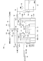
- FIG. 2 is a diagram schematically showing an example of the configuration of the liquid processing unit 34A in the substrate processing apparatus according to the present embodiment.
- the configurations of the liquid treatment unit 34B and the liquid treatment unit 34C are also the same as in the case where an example is shown in FIG.
- the liquid processing unit 34A has a box-shaped processing chamber 50 having an internal space and a central portion of the substrate W while holding one substrate W in a horizontal posture in the processing chamber 50.
- a spin chuck 51 for rotating the substrate W around the vertical rotation axis Z2 passing through the substrate W and a tubular processing cup 511 surrounding the spin chuck 51 around the rotation axis Z2 of the substrate W are provided.
- the processing chamber 50 is surrounded by a box-shaped partition wall 50A.
- the partition wall 50A is formed with an opening 50B for carrying in and out the substrate W into the processing chamber 50.
- the opening 50B is opened and closed by the shutter 50C.
- the shutter 50C has a closed position (indicated by a two-dot chain line in FIG. 2) that covers the opening 50B and an open position (solid line in FIG. 2) that opens the opening 50B by a shutter elevating mechanism (not shown here). Can be raised and lowered with (indicated by).
- the transfer robot 33 accesses the hands 33C and 33D into the processing chamber 50 through the opening 50B.
- the untreated substrate W can be arranged on the upper surface of the spin chuck 51, or the treated substrate W can be removed from the spin chuck 51.
- the spin chuck 51 includes a disc-shaped spin base 51A that vacuum-sucks the lower surface of the substrate W in a horizontal posture, and a rotation shaft 51C that extends downward from the central portion of the spin base 51A. It includes a spin motor 51D that rotates the substrate W adsorbed on the spin base 51A by rotating the rotation shaft 51C.
- the spin chuck 51 is not limited to the vacuum suction type chuck shown in FIG. 2, and includes, for example, a plurality of chuck pins protruding upward from the outer peripheral portion of the upper surface of the spin base. It may be a sandwiching type chuck that sandwiches the peripheral edge portion of the substrate W.
- the liquid treatment unit 34A has a chemical liquid nozzle 52 for discharging the chemical liquid toward the upper surface of the substrate W held by the spin chuck 51, and a chemical liquid nozzle 52 attached to the tip thereof.
- a liquid feeding device 55 for example, a pump
- a chemical liquid valve 56 that opens and closes the inside of the chemical liquid pipe 54 are provided.
- the chemical solution arm 152 includes a rotation drive source 152A, a shaft body 152B, and an arm portion 152C having one end fixed to the upper end of the shaft body 152B and the chemical solution nozzle 52 attached to the other end.
- the shaft body 152B is rotated by the rotation drive source 152A, so that the chemical solution nozzle 52 attached to the tip of the arm portion 152C is held on the upper surface of the substrate W or the dummy substrate DW held by the spin chuck 51. It can be moved along the top surface. That is, the chemical solution nozzle 52 attached to the tip of the arm portion 152C can move in the horizontal direction.
- the drive of the rotary drive source 152A is controlled by a control unit described later.
- the liquid treatment unit 34A has a circulation pipe 57 that connects the chemical liquid pipe 54 and the chemical liquid tank 53 on the upstream side (that is, the chemical liquid tank 53 side) of the chemical liquid valve 56, and a circulation valve that opens and closes the inside of the circulation pipe 57.
- the 58 and a temperature control device 59 for adjusting the temperature of the chemical solution flowing through the circulation pipe 57 are provided.
- the opening and closing of the chemical solution valve 56 and the circulation valve 58 is controlled by a control unit described later.
- the chemical solution in the chemical solution tank 53 is supplied to the chemical solution nozzle 52, the chemical solution valve 56 is opened and the circulation valve 58 is closed.
- the chemical liquid sent from the chemical liquid tank 53 to the chemical liquid pipe 54 by the liquid feeding device 55 is supplied to the chemical liquid nozzle 52.
- the temperature control device 59 regulates the temperature of the chemical solution flowing in the circulation pipe 57. Therefore, the chemical solution in the chemical solution tank 53 is heated in the circulation path while the supply is stopped, and is maintained at a temperature higher than room temperature.
- the opening degree of the chemical solution valve 56 can be adjusted so that a small amount of the chemical solution can be discharged from the chemical solution nozzle 52 to perform pre-dispensing.
- a chemical solution recovery member (not shown here) is arranged in the vicinity of the chemical solution nozzle 52, and the pre-dispensed chemical solution is collected from the chemical solution nozzle 52.
- the liquid treatment unit 34A has a rinse liquid nozzle 60 for discharging the rinse liquid toward the upper surface of the substrate W held by the spin chuck 51, and a rinse liquid nozzle 60 at the tip thereof.
- the rinse liquid arm 160 attached to the rinse liquid arm 160, the rinse liquid pipe 61 that supplies the rinse liquid from the rinse liquid supply source (not shown here) to the rinse liquid nozzle 60, and the rinse liquid nozzle 60 from the rinse liquid pipe 61. It is provided with a rinse liquid valve 62 for switching between supply and stop of the rinse liquid to.
- DIW deionized water
- the rinse liquid arm 160 includes a rotation drive source 160A, a shaft body 160B, and an arm portion 160C having one end fixed to the upper end of the shaft body 160B and a rinse liquid nozzle 60 attached to the other end.
- the shaft body 160B is rotated by the rotation drive source 160A, so that the rinse liquid nozzle 60 attached to the tip of the arm portion 160C is held on the spin chuck 51 on the upper surface of the substrate W or the dummy substrate. It becomes movable along the upper surface of the DW. That is, the rinse liquid nozzle 60 attached to the tip of the arm portion 160C can move in the horizontal direction.
- the drive of the rotary drive source 160A is controlled by a control unit described later.
- the rinse solution is supplied to the substrate W from the rinse solution nozzle 60, so that the chemical solution adhering to the substrate W can be washed away.
- the liquid treatment unit 34A includes a cleaning liquid nozzle 64 for discharging the cleaning liquid toward a predetermined portion (for example, spin base 51A) inside the processing chamber 50, and a cleaning liquid supply source (a cleaning liquid supply source (for example).
- a cleaning liquid pipe 65 for supplying the cleaning liquid from (not shown) to the cleaning liquid nozzle 64, and a cleaning liquid valve 66 for switching between supply and stop of the cleaning liquid from the cleaning liquid pipe 65 to the cleaning liquid nozzle 64 are provided.
- DIW deionized water
- the cleaning liquid nozzle 64 is attached to the inner wall of the processing chamber 50. While the substrate W or the dummy substrate DW is held by the spin chuck 51, the spin base 51A is rotated and the cleaning liquid is discharged from the cleaning liquid nozzle 64.
- the cleaning liquid discharged from the cleaning liquid nozzle 64 bounces off the upper surface of the substrate W or the upper surface of the dummy substrate DW, and the cleaning liquid is scattered in the processing chamber 50.
- various parts processing cup 511, etc. arranged in the processing chamber 50 can be cleaned.
- the processing cup 511 is provided so as to surround the spin chuck 51, and is moved up and down in the vertical direction by a motor (not shown).
- the upper portion of the processing cup 511 has an upper position in which the upper end thereof is above the substrate W or the dummy substrate DW held by the spin base 51A and a lower position in which the upper end thereof is below the substrate W or the dummy substrate DW. Go up and down between.
- the processing liquid scattered from the upper surface of the substrate W or the upper surface of the dummy substrate DW to the outside is received by the inner surface of the processing cup 511. Then, the treatment liquid received by the treatment cup 511 is appropriately drained to the outside of the treatment chamber 50 through the drainage port 513 provided at the bottom of the treatment chamber 50 and inside the treatment cup 511.
- an exhaust port 515 is provided on the side of the processing chamber 50.
- the atmosphere inside the processing chamber 50 is appropriately discharged to the outside of the processing chamber 50 through the exhaust port 515.
- the liquid treatment unit 34A includes a membrane removal liquid nozzle 164 for discharging the membrane removal liquid toward a predetermined portion (for example, spin base 51A) inside the treatment chamber 50.
- Membrane removal liquid pipe 165 that supplies the membrane removal liquid from the membrane removal liquid supply source (not shown here) to the membrane removal liquid nozzle 164, and the membrane removal liquid from the membrane removal liquid pipe 165 to the membrane removal liquid nozzle 164. It is provided with a membrane removing liquid valve 166 for switching between supply and stop of supply.
- the membrane removing solution for example, dilute hydrofluoric acid (DHF) obtained by diluting hydrofluoric acid (HF) with pure water is used. Further, by using degassed hydrofluoric acid as the membrane removing liquid, it is possible to suppress the oxidation of the substrate by oxygen contained in the treatment liquid or the like.
- DHF dilute hydrofluoric acid
- HF hydrofluoric acid
- the membrane removing liquid nozzle 164 is attached to the inner wall of the processing chamber 50. While the substrate W or the dummy substrate DW is held by the spin chuck 51, the spin base 51A is rotated and the membrane removing liquid is discharged from the membrane removing liquid nozzle 164.
- the film removing liquid discharged from the film removing liquid nozzle 164 is a film formed on the upper surface of the substrate W or the upper surface of the dummy substrate DW (hereinafter, also referred to as a removal target film). To remove.
- the liquid treatment unit 34A includes a film thickness measuring device 81 for measuring the film thickness of the film formed on the upper surface of the substrate W or the upper surface of the dummy substrate DW, and a film thickness.
- the measuring instrument 81 is provided with a measuring arm 181 attached to the tip thereof.
- the film thickness measuring device 81 for example, an optical displacement sensor or the like is used. By adjusting the measurement irradiation wavelength of the light emitted from the film thickness measuring device 81 to the substrate W or the like facing the film during measurement according to the film to be measured (hereinafter, also referred to as the film to be measured), various measures can be taken. It is possible to measure the thickness of the film to be measured (for example, a silicon film, and further, a film in which a cleaning treatment liquid or a drying treatment liquid is changed into a film due to coagulation or the like).
- the measuring arm 181 includes a rotation drive source 181A, a shaft body 181B, and an arm portion 181C having one end fixed to the upper end of the shaft body 181B and a film thickness measuring device 81 attached to the other end.
- the shaft body 181B is rotated by the rotation drive source 181A, so that the film thickness measuring instrument 81 attached to the tip of the arm portion 181C is held on the spin chuck 51 on the upper surface of the substrate W or the dummy substrate. It becomes movable along the upper surface of the DW. That is, the film thickness measuring instrument 81 attached to the tip of the arm portion 181C can move in the horizontal direction.
- the drive of the rotary drive source 181A is controlled by a control unit described later.
- the measurement arm 181 is located at least farther from the upper surface of the substrate W or the upper surface of the dummy substrate DW than the chemical solution arm 152 or the rinse solution arm 160. That is, the vertical height H1 of the measuring arm 181 (the length from the upper surface of the spin base 51A to the arm portion 181C or the film thickness measuring instrument 81) is the vertical height H2 of the chemical solution arm 152 (the spin base 51A). It is higher than the vertical height H3 (the length from the upper surface of the spin base 51A to the arm portion 160C or the rinse liquid nozzle 60) or the height H3 in the vertical direction of the rinse liquid arm 160 (the length from the upper surface to the arm portion 152C or the chemical liquid nozzle 52).
- the measuring arm 181 since the measuring arm 181 is located away from the upper surface of the substrate W or the upper surface of the dummy substrate DW, it rebounds when the chemical solution or the like is discharged to the upper surface of the substrate W or the upper surface of the dummy substrate DW. It is possible to prevent the liquid and the like from adhering to the film thickness measuring instrument 81.
- the measuring arm 181 may be located farther from the upper surface of the spin base 51A than both the chemical solution arm 152 and the rinsing solution arm 160.
- FIG. 3 is a plan view showing an example of the position of each arm in the liquid treatment unit 34A.
- the chemical solution arm 152, the rinsing solution arm 160, and the measurement arm 181 are each movable in the radial direction (at least, the direction having the radial component) of the spin base 51A, and spin.
- the upper surface of the rotating substrate W or the upper surface of the dummy substrate DW can be scanned by the chuck 51.
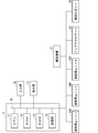
- FIG. 4 is a functional block diagram showing an example of the connection relationship between each element of the substrate processing device 1 and the control unit 7.
- control unit 7 has a central processing unit (CPU) 71 that performs various arithmetic processes and a read-only memory (read only memory, that is, ROM) that is a read-only memory that stores a basic program. ) 72, a random access memory (RAM) 73 which is a readable and writable memory for storing various information, and a non-transient storage unit 74 for storing a control application (program) or data. And.
- CPU central processing unit
- ROM read only memory
- RAM random access memory
- non-transient storage unit 74 for storing a control application (program) or data.
- the CPU 71, ROM 72, RAM 73, and storage unit 74 are connected to each other by bus wiring 75 or the like.
- the control application or data may be provided to the control unit 7 in a state of being recorded on a non-transient recording medium (for example, semiconductor memory, optical media, magnetic media, etc.).
- a reading device that reads the control application or data from the recording medium may be connected to the bus wiring 75.
- control application or data may be provided to the control unit 7 from a server or the like via a network.
- the communication unit that performs network communication with the external device is connected to the bus wiring 75.
- the input unit 76 and the display unit 77 are connected to the bus wiring 75.
- the input unit 76 includes various input devices such as a keyboard and a mouse.
- the operator inputs various information to the control unit 7 via the input unit 76.
- the display unit 77 is composed of a display device such as a liquid crystal monitor, and displays various information.
- the control unit 7 is a drive unit that drives the operating unit of each liquid treatment unit (for example, the chemical liquid valve 56, the circulation valve 58, the rinse liquid valve 62, the cleaning liquid valve 66, the shutter 50C or the spin motor 51D), and the transfer mechanism 31.
- a motor for reciprocating movement of the transfer mechanism 31 an operating part of the indexer robot 23 (for example, a motor for driving the articulated arm 23B), an operating part of the transfer robot 33 (for example, a horizontal motor 133C). , Rotating motor 133D, vertical motor 133H, etc.) and controls their operation.
- the substrate W housed in the substrate container 21 is carried into one of the liquid processing units via the indexer robot 23, the transfer mechanism 31, and the transfer robot 33, and the substrate W is further loaded. This is an operation related to chemical liquid treatment performed by the substrate processing apparatus 1 while being held by the spin chuck 51.
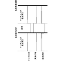
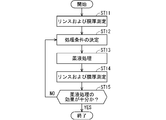
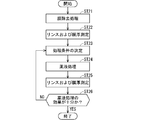
- FIG. 5 is a sequence diagram showing an example of the operation related to the above-mentioned chemical treatment. Further, FIG. 6 is a flowchart showing an example of the operation related to the chemical treatment according to FIG.
- a rinsing process is performed (step ST1 in FIG. 6).
- the rinsing liquid is discharged from the rinsing liquid nozzle 60 under the control of the control unit 7, so that deposits and the like on the upper surface of the substrate W can be washed away.
- the rinsing solution for example, DIW (deionized water) is used.
- a drying process is performed (step ST2 in FIG. 6).
- the substrate W is dried by rotating the spin base 51A after supplying IPA (isopropyl alcohol) or the like to the substrate W under the control of the control unit 7.
- IPA isopropyl alcohol
- the film thickness is measured (step ST3 in FIG. 6).
- the arm portion 181C of the measuring arm 181 is rotated under the control of the control unit 7, and the film thickness measuring device 81 attached to the tip of the arm portion 181C faces an arbitrary position on the upper surface of the substrate W. And place it.
- the film thickness measuring device 81 measures the film thickness of the film (measurement target film) formed on the upper surface of the substrate W to be processed.
- the film (measurement target film) formed on the upper surface of the substrate W is, for example, a silicon film formed on the upper surface of the silicon semiconductor substrate.
- the processing conditions are determined based on the result of the film thickness measurement (step ST4 in FIG. 6). Specifically, the concentration of the chemical solution used for the chemical solution treatment, the time of the chemical solution treatment, and the like are adjusted based on the result of the film thickness measurement.
- step ST5 in FIG. 6 chemical treatment is performed (step ST5 in FIG. 6).
- the substrate W is etched or the like by ejecting the chemical from the chemical nozzle 52 under the control of the control unit 7.
- the substrate W is etched using hydrofluoric acid (HF) and nitric acid (HNO 3 ), which is a mixed solution of nitric acid.
- HF hydrofluoric acid
- HNO 3 nitric acid
- the rinsing process is performed (step ST6 in FIG. 6).
- the rinsing liquid is discharged from the rinsing liquid nozzle 60 under the control of the control unit 7, so that the chemical liquid and the like on the upper surface of the substrate W can be washed away.
- the rinsing solution for example, DIW (deionized water) is used.
- step ST7 in FIG. 6 a drying process is performed (step ST7 in FIG. 6).
- the drying treatment is the same as the drying treatment in step ST2.
- the film thickness is measured (step ST8 in FIG. 6).
- the arm portion 181C of the measuring arm 181 is rotated under the control of the control unit 7, and the film thickness measuring device 81 attached to the tip of the arm portion 181C is placed at an arbitrary position on the upper surface of the substrate W. Place them facing each other.
- the film thickness measuring device 81 measures the film thickness of the film (measurement target film) formed on the upper surface of the substrate W after the chemical treatment.
- step ST9 in FIG. 6 the effect of the chemical treatment is confirmed based on the result of the film thickness measurement. Specifically, whether or not it is necessary to perform the chemical treatment again based on the result of the film thickness measurement in step ST8 or the result of the film thickness measurement in step ST3 and the result of the film thickness measurement in step ST8. Is judged.
- step ST9 the process returns to step ST4 shown in FIG.
- the treatment conditions such as the concentration of the chemical solution used for the chemical solution treatment and the time of the chemical solution treatment are determined based on the result of the film thickness measurement.
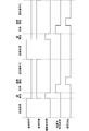
- FIG. 7 is a sequence diagram showing a modified example of the operation related to the above-mentioned chemical treatment. Further, FIG. 8 is a flowchart showing a modified example of the operation related to the chemical treatment according to FIG. 7.
- rinsing treatment and film thickness measurement are performed (step ST11 in FIG. 8).
- the rinsing treatment is the same as the rinsing treatment in step ST1 of FIG.
- the film thickness measurement is the same as the film thickness measurement in step ST3 of FIG.
- the rinsing liquid arm 160 can rotate for rinsing treatment.
- the measuring arm 181 can rotate for film thickness measurement.
- the height H3 of the rinsing liquid arm 160 and the height H1 of the measuring arm 181 are different, they can operate without interfering with each other.
- the measurement irradiation wavelength range of the light used for film thickness measurement is outside the absorption wavelength range of the rinse liquid.
- the measurement irradiation wavelength range is about 890 nm to 1640 nm, and the absorption wavelength range when DIW (deionized water) is used as the rinsing solution.
- the entire range is out of range for a certain 2 ⁇ m to 10 ⁇ m.
- the processing conditions are determined based on the result of the film thickness measurement (step ST12 in FIG. 8).
- the determination of the processing conditions is the same as the determination of the processing conditions in step ST4 of FIG.
- step ST13 in FIG. 8 chemical treatment is performed (step ST13 in FIG. 8).
- the chemical treatment is the same as the chemical treatment in step ST5 of FIG. If necessary, a drying treatment may be performed before the chemical treatment.
- rinsing treatment and film thickness measurement are performed (step ST14 in FIG. 8).
- the rinsing treatment is the same as the rinsing treatment in step ST6 of FIG.
- the film thickness measurement is the same as the film thickness measurement in step ST8 of FIG.
- the rinsing liquid arm 160 can rotate for rinsing treatment.
- the measuring arm 181 can rotate for film thickness measurement.
- the height H3 of the rinsing liquid arm 160 and the height H1 of the measuring arm 181 are different, they can operate without interfering with each other.
- step ST15 in FIG. 8 the effect of the chemical treatment is confirmed based on the result of the film thickness measurement.
- step ST15 shown in FIG. 8 the process returns to step ST12 shown in FIG. Then, the treatment conditions such as the concentration of the chemical solution used for the chemical solution treatment and the time of the chemical solution treatment are determined based on the result of the film thickness measurement.
- the film thickness measurement in step ST14 may be performed even while the chemical solution treatment in step ST13 is being performed. In this case as well, it is assumed that at least a part of the measurement irradiation wavelength range of the light used for the film thickness measurement is outside the absorption wavelength range of the chemical solution.
- the chemical solution arm 152 can rotate for the chemical solution treatment.
- the measuring arm 181 can rotate for film thickness measurement.
- the height H2 of the chemical solution arm 152 and the height H1 of the measuring arm 181 are different, they can operate without interfering with each other.
- the treatment content can be corrected at an early timing. Therefore, the degree of freedom of correction is increased, and as a result, the processing accuracy is improved.
- FIG. 9 is a sequence diagram showing a modified example of the operation related to the above-mentioned chemical treatment. Further, FIG. 10 is a flowchart showing a modified example of the operation related to the chemical treatment according to FIG.
- the film removing treatment is further added to the operation shown in FIG. 7.
- the accuracy of the film thickness measurement is improved.
- a rinsing treatment is performed, and then a film removal treatment is performed (step ST21 in FIG. 10).
- the film removing liquid is discharged from the film removing liquid nozzle 164 under the control of the control unit 7, so that the film is formed on the upper surface of the film (measurement target film) formed on the upper surface of the substrate W.
- the membrane is removed.
- the film to be removed (film to be removed) is, for example, a silicon oxide film. However, the film to be removed may be another oxide film or nitride film including a naturally occurring film.
- step ST22 in FIG. 10 rinsing treatment and film thickness measurement are performed.
- the process is the same as the process in step ST11 of FIG.
- the processing conditions are determined based on the result of the film thickness measurement (step ST23 in FIG. 10).
- the determination of the processing conditions is the same as the determination of the processing conditions in step ST12 of FIG.
- step ST24 in FIG. 10 chemical treatment is performed (step ST24 in FIG. 10).
- the chemical treatment is the same as the chemical treatment in step ST13 of FIG. If necessary, a drying treatment may be performed before the chemical treatment.
- step ST25 in FIG. 10 rinsing treatment and film thickness measurement are performed.
- the process is the same as the process in step ST14 of FIG.
- step ST26 in FIG. 10 the effect of the chemical treatment is confirmed based on the result of the film thickness measurement.
- step ST26 shown in FIG. 10
- the process returns to step ST23 shown in FIG. Then, the treatment conditions such as the concentration of the chemical solution used for the chemical solution treatment and the time of the chemical solution treatment are determined based on the result of the film thickness measurement.
- the film thickness can be measured after the film to be removed formed on the upper surface of the film to be measured can be reliably removed.
- the measurement accuracy of the film thickness of the film to be measured is improved.
- the film thickness measurement in step ST25 may be performed even while the chemical treatment in step ST24 is being performed. In this case as well, it is assumed that at least a part of the measurement irradiation wavelength range of the light used for the film thickness measurement is outside the absorption wavelength range of the chemical solution.
- drying treatment may be performed after the rinsing treatment as in the example shown in FIG. 5 without performing the rinsing treatment and the film thickness measurement at the same time.
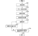
- FIG. 11 is a sequence diagram showing an example of the operation related to the above-mentioned processing chamber cleaning. Further, FIG. 12 is a flowchart showing an example of the operation related to the cleaning of the processing chamber corresponding to FIG.
- the substrate processing is a processing corresponding to the operation related to the chemical solution processing performed by the substrate processing apparatus 1.
- the transfer robot 33 carries out one processed substrate W from, for example, the liquid processing unit 34A by using, for example, the hand 33D. Then, the transfer robot 33 passes the substrate W to the transfer mechanism 31.
- the transfer robot 33 uses, for example, the hand 33C to carry out one dummy board DW housed in the dummy board container 32. Then, the transfer robot 33 arranges the dummy substrate DW on the upper surface of the spin base 51A in the liquid processing unit 34A, for example.
- the film removal process is performed (step ST33 in FIG. 12).
- the film removing liquid is discharged from the film removing liquid nozzle 164 under the control of the control unit 7, so that the film is formed on the upper surface of the film (measurement target film) formed on the upper surface of the dummy substrate DW.
- the existing film (membrane to be removed) is removed.
- the film to be removed is, for example, a silicon oxide film. However, the film to be removed may be another oxide film or nitride film including a naturally occurring film.
- deposits such as dust adhering to the upper surface of the dummy substrate DW while being housed in the dummy substrate container 32 may also be removed.
- the processing chamber cleaning process is performed (step ST34 in FIG. 12).
- the cleaning liquid is discharged from the cleaning liquid nozzle 64 under the control of the control unit 7, so that the cleaning liquid bounces off the upper surface of the dummy substrate DW and the cleaning liquid is scattered in the processing chamber 50.
- DIW deionized water
- the film thickness is measured (step ST35 in FIG. 12).
- the arm portion 181C of the measuring arm 181 is rotated under the control of the control unit 7, and the film thickness measuring instrument 81 attached to the tip of the arm portion 181C is mounted on the upper surface of the dummy substrate DW on the spin base 51A. It is arranged to face an arbitrary position in.
- the film thickness measuring device 81 measures the film thickness of the film (for example, a silicon film) formed on the upper surface of the dummy substrate DW to be processed.
- the thickness of the measurement target film formed on the upper surface of the dummy substrate DW is a known value. Therefore, in the film thickness measurement, it is confirmed whether or not the known thickness of the film to be measured formed on the upper surface of the dummy substrate DW is reproduced by the measurement (step ST36 in FIG. 12).
- step ST36 when the result of the above film thickness measurement does not reproduce the known thickness of the film to be measured, that is, when it corresponds to "NO" branched from step ST36 shown in FIG. 12 as an example.
- the film thickness measuring instrument 81 and related equipment are calibrated by the control of the control unit 7 (step ST37 in FIG. 12). Specifically, the film thickness measuring instrument 81 and related equipment so that the measured value of the film formed on the upper surface of the dummy substrate DW and having a known thickness by the film thickness measuring instrument 81 approaches the known value. To calibrate. Then, the process returns to step ST35, and the film thickness is measured again.
- the film removal process is performed to improve the accuracy of film thickness measurement, but the process may be omitted.
- the ratio of the processing time between the processing room cleaning and the film thickness measurement can be, for example, 8: 2.
- the substrate processing apparatus includes a substrate holding portion, a first arm, and a second arm.
- the substrate holding portion corresponds to, for example, the spin chuck 51.
- the first arm corresponds to, for example, the measurement arm 181.
- the second arm corresponds to, for example, any one of the chemical solution arm 152 and the rinse solution arm 160.
- the spin chuck 51 holds a substrate having a film to be measured formed on the upper surface thereof.
- the substrate corresponds to, for example, any one of the substrate W and the dummy substrate DW.
- a film thickness measuring device 81 for measuring the film thickness of the film to be measured is attached to the measuring arm 181. Further, the measuring arm 181 is rotatable on a surface along the upper surface of the substrate.
- the rinse liquid arm 160 or the chemical liquid arm 152 is attached with a first discharge nozzle for discharging the treatment liquid for processing the substrate.
- the first discharge nozzle corresponds to, for example, a rinse liquid nozzle 60 or a chemical liquid nozzle 52.
- the rinse liquid arm 160 and the chemical liquid arm 152 are rotatable on a surface along the upper surface of the substrate.
- the first distance (corresponding to the height H1 in FIG. 2), which is the distance between the measuring arm 181 and the upper surface of the spin chuck 51, is the distance between the rinse liquid arm 160 or the chemical liquid arm 152 and the upper surface of the spin chuck 51. It is longer than the second distance (corresponding to height H3 or height H2 in FIG. 2), which is the distance between.
- the film thickness measuring device 81 is attached, and the measuring arm 181 that is rotatable on the surface along the upper surface of the substrate is provided, so that the degree of freedom of the measuring point of the film thickness measurement is increased. Can be done. Further, since the height H1 of the measuring arm 181 is higher than the height H3 of the rinsing liquid arm 160 or the height H2 of the chemical liquid arm 152, even if both arms rotate at the same time, they do not collide. Further, since the measurement arm 181 is not located below the rinse liquid nozzle 60 or the chemical liquid nozzle 52, the processing liquid discharged from both the rinse liquid arm 160 and the chemical liquid arm 152 is erroneously measured. It does not adhere to 181.
- the substrate processing apparatus operates at least the film thickness measuring device 81, the measuring arm 181 and the rinsing liquid nozzle 60, the rinsing liquid arm 160, the chemical liquid nozzle 52, and the chemical liquid arm 152.
- a control unit 7 for controlling is provided.
- the control unit 7 measures the film thickness of the film to be measured by the film thickness measuring device 81 on the measuring arm 181 and discharges the treatment liquid by the rinsing liquid nozzle 60 (or the chemical liquid nozzle 52) on the rinsing liquid arm 160 (or the chemical liquid arm 152). To be done in parallel. With such a configuration, it is possible to perform parallel processing of substrate processing using a processing liquid and film thickness measurement. Therefore, the total processing time can be shortened.
- the processing content can be corrected at an early timing. Therefore, the degree of freedom of correction is increased, and as a result, the processing accuracy is improved. Further, when the substrate processing and the film thickness measurement are performed in parallel, the height H1 of the measuring arm 181 is higher than the height H3 of the rinse liquid arm 160 or the height H2 of the chemical liquid arm 152, so that the substrate is repelled. It is possible to prevent the treated liquid from adhering to the film thickness measuring device 81.
- the substrate processing apparatus includes a second discharge nozzle for discharging a film removing liquid for removing the removal target film formed on the upper surface of the measurement target film.
- the second discharge nozzle corresponds to, for example, the membrane removing liquid nozzle 164.
- the control unit 7 also controls the operation of the membrane removing liquid nozzle 164. Then, the control unit 7 removes the film to be removed by discharging the film removing liquid from the film removing liquid nozzle 164, and then informs the film thickness measuring device 81 of the film thickness of the film to be measured from which the film to be removed has been removed. Let me measure. According to such a configuration, the removal target film formed on the upper surface of the measurement target film can be removed before the film thickness measurement, so that the accuracy of the film thickness measurement is improved.
- control unit 7 adjusts the time for the chemical solution nozzle 52 to discharge the treatment liquid based on the result of the film thickness measurement of the film to be measured by the film thickness measuring device 81.
- the treatment conditions can be determined before the chemical treatment, and the effect of the chemical treatment can be confirmed after the chemical treatment, based on the result of the film thickness measurement. Can be done.
- the substrate is a dummy substrate DW on which a measurement target film having a predetermined thickness is formed on the upper surface.
- the control unit 7 calibrates the film thickness measuring device 81 based on the result of measuring the film thickness of the film to be measured on the upper surface of the dummy substrate DW by the film thickness measuring device 81.
- the film thickness measuring device 81 can be calibrated. Therefore, the reproducibility of the film thickness measurement by the film thickness measuring device 81 can be maintained high, and the accuracy of the film thickness measurement can be improved.
- the film thickness measuring instrument 81 is an optical displacement sensor. Then, at least a part of the measurement irradiation wavelength range of the film thickness measuring device 81 is outside the absorption wavelength range of the treatment liquid. According to such a configuration, the light emitted from the film thickness measuring device 81 is reflected without being absorbed by the treatment liquid and can be received by the film thickness measuring device 81. Therefore, the film thickness is measured due to the influence of the substrate processing. It is possible to suppress a decrease in the accuracy of.
- the entire range of the measurement irradiation wavelength of the film thickness measuring device 81 is outside the range of the absorption wavelength of the treatment liquid. According to such a configuration, the light in the entire wavelength range emitted from the film thickness measuring instrument 81 is reflected without being absorbed by the processing liquid and can be received by the film thickness measuring instrument 81, so that the influence of the substrate processing It is possible to prevent the accuracy of film thickness measurement from being lowered.
- the present invention includes a step of processing the substrate using the processing liquid discharged from the nozzle 60 (or the chemical solution nozzle 52).
- the height H1 corresponding to the distance between the measuring arm 181 and the upper surface of the spin chuck 51 is the height corresponding to the distance between the rinse liquid arm 160 (or the chemical liquid arm 152) and the upper surface of the spin chuck 51. Longer than H3 (or height H2).
- the film thickness measuring device 81 is attached, and the measuring arm 181 that is rotatable on the surface along the upper surface of the substrate is provided, so that the degree of freedom of the measuring point of the film thickness measurement is increased. Can be done.
- the step of processing the substrate using the treatment liquid discharged from the liquid nozzle 60 (or the chemical liquid nozzle 52) is performed in parallel. With such a configuration, it is possible to perform parallel processing of substrate processing using a processing liquid and film thickness measurement. Therefore, the total processing time can be shortened.
- the removal target film formed on the upper surface of the measurement target film is removed before the film thickness of the measurement target film is measured by the film thickness measuring device 81.
- a step of discharging a film removing liquid for the purpose is provided. According to such a configuration, the removal target film formed on the upper surface of the measurement target film can be removed before the film thickness measurement, so that the accuracy of the film thickness measurement is improved.
- the time for the chemical solution nozzle 52 to discharge the processing solution is adjusted based on the result of the film thickness measurement of the film to be measured by the film thickness measuring device 81.
- the treatment conditions can be determined before the chemical treatment, and the effect of the chemical treatment can be confirmed after the chemical treatment, based on the result of the film thickness measurement. Can be done.
- the substrate is a dummy substrate DW having a measurement target film having a predetermined thickness formed on the upper surface thereof. Then, in the substrate processing method, a step of calibrating the film thickness measuring device 81 based on the result of measuring the film thickness of the film to be measured on the upper surface of the dummy substrate DW is provided. According to such a configuration, using a measurement target film whose thickness on the upper surface of the dummy substrate DW is known, it is confirmed whether or not the value measured by the film thickness measuring device 81 has reproducibility, and further. If necessary, the film thickness measuring device 81 can be calibrated.
- the film removing liquid nozzle 164 may be attached to the tip of an arm that can move along the upper surface of the substrate W or the upper surface of the dummy substrate DW.
- the chemical solution nozzle 52, the rinse solution nozzle 60, and the membrane removing solution nozzle 164 may be attached to the tip of the same arm.
- the film thickness measuring device 81 in the above embodiment is an optical displacement sensor that measures a solidified film in which the treatment liquid or the like has changed due to solidification or the like, but can also measure a liquid or amorphous film.
- a film thickness measuring device may be used.
- the target film may be removed by, for example, increasing the rotation speed of the spin base 51A to scatter the treatment liquid and drain it.
- each component described in the above-described embodiment is assumed to be software or firmware and corresponding hardware, and in both concepts, each component is a "part”. Alternatively, it is referred to as a "processing circuit” or the like.
Landscapes
- Cleaning Or Drying Semiconductors (AREA)
- Weting (AREA)
Abstract
膜厚測定の測定箇所の自由度を高める。基板処理装置は、上面に測定対象膜が形成された基板を保持するための基板保持部と、測定対象膜の膜厚を測定するための膜厚測定器が取り付けられ、かつ、基板の上面に沿う面において回動可能な第1のアームと、基板を処理するための処理液を吐出するための第1の吐出ノズルが取り付けられ、かつ、基板の上面に沿う面において回動可能な第2のアームとを備え、第1のアームと基板保持部の上面との間の距離である第1の距離が、第2のアームと基板保持部の上面との間の距離である第2の距離よりも長い。
Description
本願明細書に開示される技術は、基板処理装置、および、基板処理方法に関するものである。なお、処理対象となる基板には、たとえば、半導体基板、液晶表示装置または有機EL(electroluminescence)表示装置などのflat panel display(FPD)用基板、光ディスク用基板、磁気ディスク用基板、光磁気ディスク用基板、フォトマスク用基板、セラミック基板、プリント基板、または、太陽電池用基板などが含まれる。
従来より、半導体基板(以下、単に「基板」と称する)の製造工程では、基板処理装置を用いて基板に対して様々な処理が行われている。当該処理には、当該基板の上面に形成された膜を処理液を用いて除去するエッチング処理が含まれる。
そして、上記の膜に対する処理の効果を確認するため、上記の膜の膜厚測定が行われている(たとえば、特許文献1を参照)。
上記の膜厚測定は、たとえば、基板の上方の一点に固定された膜厚測定器を用いて行われるものであった。よって、膜厚測定が可能な測定箇所が制限されてしまうため、所望の箇所における膜厚測定が困難となる場合があった。
本願明細書に開示される技術は、以上に記載されたような問題を鑑みてなされたものであり、上記の膜厚測定の測定箇所の自由度を高める技術を提供することを目的とするものである。
本願明細書に開示される技術の第1の態様は、上面に測定対象膜が形成された基板を保持するための基板保持部と、前記測定対象膜の膜厚を測定するための膜厚測定器が取り付けられ、かつ、前記基板の上面に沿う面において回動可能な第1のアームと、前記基板を処理するための処理液を吐出するための第1の吐出ノズルが取り付けられ、かつ、前記基板の上面に沿う面において回動可能な第2のアームとを備え、前記第1のアームと前記基板保持部の上面との間の距離である第1の距離が、前記第2のアームと前記基板保持部の上面との間の距離である第2の距離よりも長い。
本願明細書に開示される技術の第2の態様は、第1の態様に関連し、少なくとも前記膜厚測定器、前記第1のアーム、前記第1の吐出ノズルおよび前記第2のアームの動作を制御する制御部をさらに備え、前記制御部は、前記第1のアームにおける前記膜厚測定器による前記測定対象膜の膜厚測定と、前記第2のアームにおける前記第1の吐出ノズルによる前記処理液の吐出とを並行して行わせる。
本願明細書に開示される技術の第3の態様は、第2の態様に関連し、前記測定対象膜の上面に形成される除去対象膜を除去するための膜除去液を吐出する第2の吐出ノズルをさらに備え、前記制御部は、前記第2の吐出ノズルの動作も制御し、前記制御部は、前記第2の吐出ノズルから前記膜除去液を吐出させることによって前記除去対象膜を除去した後、前記膜厚測定器に、前記除去対象膜が除去された前記測定対象膜の膜厚を測定させる。
本願明細書に開示される技術の第4の態様は、第2または3の態様に関連し、前記制御部は、前記膜厚測定器による前記測定対象膜の膜厚測定の結果に基づいて、前記第1の吐出ノズルが前記処理液を吐出する時間を調整する。
本願明細書に開示される技術の第5の態様は、第1から4のうちのいずれか1つの態様に関連し、前記膜厚測定器が、光学式の変位センサであり、前記膜厚測定器の測定照射波長の範囲の少なくとも一部が、前記処理液の吸収波長の範囲外である。
本願明細書に開示される技術の第6の態様は、第5の態様に関連し、前記膜厚測定器の測定照射波長の全範囲が、前記処理液の吸収波長の範囲外である。
本願明細書に開示される技術の第7の態様は、上面にあらかじめ定められた厚さの測定対象膜が形成された基板を保持するための基板保持部と、前記測定対象膜の膜厚を測定するための膜厚測定器が取り付けられ、かつ、前記基板の上面に沿う面において回動可能な第1のアームと、前記基板を処理するための処理液を吐出するための第1の吐出ノズルが取り付けられ、かつ、前記基板の上面に沿う面において回動可能な第2のアームと、少なくとも前記膜厚測定器を制御する制御部とを備え、前記制御部は、前記膜厚測定器による、前記基板の上面における前記測定対象膜の膜厚測定の結果に基づいて、前記膜厚測定器の校正を行う。
本願明細書に開示される技術の第8の態様は、上面に測定対象膜が形成された基板を保持するための基板保持部と、前記測定対象膜の膜厚を測定するための膜厚測定器が取り付けられ、かつ、前記基板の上面に沿う面において回動可能な第1のアームと、前記基板を処理するための処理液を吐出するための第1の吐出ノズルが取り付けられ、かつ、前記基板の上面に沿う面において回動可能な第2のアームとを備える基板処理装置を用いる基板処理方法であり、前記膜厚測定器を用いて前記測定対象膜の膜厚を測定する工程と、前記第1の吐出ノズルから吐出される前記処理液を用いて前記基板を処理する工程とを備え、前記第1のアームと前記基板保持部の上面との間の距離である第1の距離が、前記第2のアームと前記基板保持部の上面との間の距離である第2の距離よりも長い。
本願明細書に開示される技術の第9の態様は、第8の態様に関連し、前記第1のアームにおける前記膜厚測定器を用いて前記測定対象膜の膜厚を測定する工程と、前記第2のアームにおける前記第1の吐出ノズルから吐出される前記処理液を用いて前記基板を処理する工程とを並行して行う。
本願明細書に開示される技術の第10の態様は、第8または9の態様に関連し、前記膜厚測定器による前記測定対象膜の膜厚測定の前に、前記測定対象膜の上面に形成される除去対象膜を除去するための膜除去液を吐出する工程をさらに備える。
本願明細書に開示される技術の第11の態様は、第8から10のうちのいずれか1つの態様に関連し、前記膜厚測定器による前記測定対象膜の膜厚測定の結果に基づいて、前記第1の吐出ノズルが前記処理液を吐出する時間を調整する工程をさらに備える。
本願明細書に開示される技術の第12の態様は、上面にあらかじめ定められた厚さの測定対象膜が形成された基板を保持するための基板保持部と、前記測定対象膜の膜厚を測定するための膜厚測定器が取り付けられ、かつ、前記基板の上面に沿う面において回動可能な第1のアームと、前記基板を処理するための処理液を吐出するための第1の吐出ノズルが取り付けられ、かつ、前記基板の上面に沿う面において回動可能な第2のアームとを備える基板処理装置を用いる基板処理方法であり、前記膜厚測定器を用いて前記測定対象膜の膜厚を測定する工程と、前記第1の吐出ノズルから吐出される前記処理液を用いて前記基板を処理する工程と、前記基板の上面における前記測定対象膜の膜厚測定の結果に基づいて、前記膜厚測定器の校正を行う工程とを備える。
本願明細書に開示される技術の第1から12の態様によれば、膜厚測定器が取り付けられ、かつ、基板の上面に沿う面において回動可能な第1のアームを備えることによって、膜厚測定の測定箇所の自由度を高めることができる。
また、本願明細書に開示される技術に関連する目的と、特徴と、局面と、利点とは、以下に示される詳細な説明と添付図面とによって、さらに明白となる。
以下、添付される図面を参照しながら実施の形態について説明する。以下の実施の形態では、技術の説明のために詳細な特徴なども示されるが、それらは例示であり、実施の形態が実施可能となるためにそれらすべてが必ずしも必須の特徴ではない。
なお、図面は概略的に示されるものであり、説明の便宜のため、適宜、構成の省略、または、構成の簡略化が図面においてなされるものである。また、シーケンス図における時間幅は、実際の時間幅を厳密に示すものではない。また、異なる図面にそれぞれ示される構成などの大きさおよび位置の相互関係は、必ずしも正確に記載されるものではなく、適宜変更され得るものである。また、断面図ではない平面図などの図面においても、実施の形態の内容を理解することを容易にするために、ハッチングが付される場合がある。
また、以下に示される説明では、同様の構成要素には同じ符号を付して図示し、それらの名称と機能とについても同様のものとする。したがって、それらについての詳細な説明を、重複を避けるために省略する場合がある。
また、以下に記載される説明において、ある構成要素を「備える」、「含む」または「有する」などと記載される場合、特に断らない限りは、他の構成要素の存在を除外する排他的な表現ではない。
また、以下に記載される説明において、「第1の」または「第2の」などの序数が用いられる場合があっても、これらの用語は、実施の形態の内容を理解することを容易にするために便宜上用いられるものであり、これらの序数によって生じ得る順序などに限定されるものではない。
また、以下に記載される説明における、相対的または絶対的な位置関係を示す表現、たとえば、「一方向に」、「一方向に沿って」、「平行」、「直交」、「中心」、「同心」または「同軸」などは、特に断らない限りは、その位置関係を厳密に示す場合、および、公差または同程度の機能が得られる範囲において角度または距離が変位している場合を含むものとする。
また、以下に記載される説明において、等しい状態であることを示す表現、たとえば、「同一」、「等しい」、「均一」または「均質」などは、特に断らない限りは、厳密に等しい状態であることを示す場合、および、公差または同程度の機能が得られる範囲において差が生じている場合を含むものとする。
また、以下に記載される説明における、「対象物を特定の方向に移動させる」などの表現は、特に断らない限りは、対象物を当該特定の方向と平行に移動させる場合、および、対象物を当該特定の方向の成分を有する方向に移動させる場合を含むものとする。
また、以下に記載される説明において、「上」、「下」、「左」、「右」、「側」、「底」、「表」または「裏」などの特定の位置と方向とを意味する用語が用いられる場合があっても、これらの用語は、実施の形態の内容を理解することを容易にするために便宜上用いられるものであり、実際に実施される際の方向とは関係しないものである。
また、以下に記載される説明において、「…の上面」または「…の下面」などと記載される場合、対象となる構成要素の上面自体に加えて、対象となる構成要素の上面に他の構成要素が形成された状態も含むものとする。すなわち、たとえば、「甲の上面に設けられる乙」と記載される場合、甲と乙との間に別の構成要素「丙」が介在することを妨げるものではない。
また、以下に記載される説明において、形状を示す表現、たとえば、「四角形状」または「円筒形状」などは、特に断らない限りは、厳密にその形状であることを示す場合、および、公差または同程度の機能が得られる範囲において凹凸または面取りなどが形成されている場合を含むものとする。
<実施の形態>
以下、本実施の形態に関する基板処理装置、および、基板処理方法について説明する。
以下、本実施の形態に関する基板処理装置、および、基板処理方法について説明する。
<基板処理装置の構成について>
図1は、本実施の形態に関する基板処理装置の構成の例を概略的に示す図である。なお、構成を理解しやすくする観点から、当該図面においては、一部の構成要素が省略、または、簡略化されて示される場合がある。
図1は、本実施の形態に関する基板処理装置の構成の例を概略的に示す図である。なお、構成を理解しやすくする観点から、当該図面においては、一部の構成要素が省略、または、簡略化されて示される場合がある。
基板処理装置1は、半導体ウエハなどの円板状の基板Wを1枚ずつ処理する枚葉式の処理装置である。基板処理装置1は、基板Wに対して洗浄処理またはエッチング処理などの各種処理を行う。
図1に例が示されるように、基板処理装置1は、X軸正方向に向かって順に、インデクサセクション2と、処理セクション3とを備える。
また、処理セクション3は、X軸正方向に向かって順に、搬送モジュール3Aと、処理モジュール3Bとを備える。
<インデクサセクション>
インデクサセクション2は、複数枚の基板Wを積層状態で収容可能な基板収容器21と、基板収容器21を支持するステージ22と、基板収容器21から未処理の基板Wを受け取り、また、処理セクション3において処理が完了した基板Wを基板収容器21へ渡すインデクサロボット23とを備える。
インデクサセクション2は、複数枚の基板Wを積層状態で収容可能な基板収容器21と、基板収容器21を支持するステージ22と、基板収容器21から未処理の基板Wを受け取り、また、処理セクション3において処理が完了した基板Wを基板収容器21へ渡すインデクサロボット23とを備える。
なお、ステージ22の数は、図1の例では簡単のため1つとされたが、それ以上の数がY軸方向に並べられていてもよい。
基板収容器21は、基板Wを密閉状態で収納するfront opening unified pod(FOUP)であってもよいし、standard mechanical inter face(SMIF)ポッド、または、open cassette(OC)などであってもよい。
インデクサロボット23は、たとえば、基台部23Aと、多関節アーム23Bと、互いに鉛直方向に間隔をあけて設けられる2つのハンド23Cおよびハンド23Dとを備える。
基台部23Aは、たとえば、基板処理装置1のインデクサセクション2の外形を規定するフレームに固定されている。
多関節アーム23Bは、水平面に沿って回動可能な複数本のアーム部が互いに回動可能に結合されて構成されており、当該アーム部の結合箇所である関節部でアーム部間の角度を変更することによって、当該アーム部が屈伸可能に構成されている。
また、多関節アーム23Bの基端部は、基台部23Aに対して、鉛直軸回りに回動可能に結合されている。さらに、多関節アーム23Bは、基台部23Aに対して昇降可能に結合されている。
ハンド23Cおよびハンド23Dは、1枚の基板Wをそれぞれ保持可能に構成されている。
インデクサロボット23は、ステージ22に保持された基板収容器21から1枚の未処理の基板Wを、たとえばハンド23Cを用いて搬出する。そして、インデクサロボット23は、X軸負方向から搬送モジュール3Aにおける搬送機構31(後述)に当該基板Wを渡す。
さらに、インデクサロボット23は、搬送機構31から1枚の処理済みの基板Wを、たとえばハンド23Dを用いて受け取る。そして、インデクサロボット23は、ステージ22に保持された基板収容器21に当該基板Wを収容する。
<処理セクション>
処理セクション3における搬送モジュール3Aは、1または複数枚の基板Wを水平姿勢に保持しつつ搬送可能な搬送機構31を備える。
処理セクション3における搬送モジュール3Aは、1または複数枚の基板Wを水平姿勢に保持しつつ搬送可能な搬送機構31を備える。
搬送機構31は、たとえば、XZ平面およびXY平面に沿って形成される隔壁(ここでは、図示しない)によって囲まれた筒状の搬送路を移動するものであってもよい。また、搬送機構31は、X軸方向に延びるレールに案内されて往復移動するものであってもよい。
搬送機構31によって、基板Wは、インデクサセクション2に近いX軸負方向の位置と、搬送ロボット33(後述)に近いX軸正方向の位置との間で搬送される。
処理セクション3における処理モジュール3Bは、複数枚のダミー基板DWを収容するダミー基板収容器32と、基板Wまたはダミー基板DWを搬送する搬送ロボット33と、搬送機構31から供給される未処理の基板Wに規定処理を行う複数の液処理ユニット34A、液処理ユニット34Bおよび液処理ユニット34Cとを備える。
ここで、ダミー基板DWとは、たとえば、液処理ユニット内の洗浄(処理室洗浄)の際に用いられる基板である。ダミー基板DWの基板自体の厚さおよび基板の上面に形成される膜(たとえば、シリコン膜)の厚さは既知である。
ダミー基板収容器32は、処理モジュール3Bのたとえば上方に位置する。また、ダミー基板収容器32において、複数枚のダミー基板DWは、積層状態で収容される。
搬送ロボット33は、水平駆動部33Aと、鉛直駆動部33Bと、ハンド33Cと、ハンド33Dと、これらの構成が連結具33Fを介して取り付けられ、かつ、鉛直方向に延びる支柱33Eとを備える。
水平駆動部33Aは、ハンド33Cおよびハンド33Dを水平方向に移動させる。水平駆動部33Aは、ステージ133Aと、ステージ133Aの上面を水平方向に往復移動する水平スライダ133Bと、水平スライダ133Bを移動させる水平モータ133Cとを備える。
ステージ133Aの上面には直線状に延びるレール(ここでは、図示せず)が設けられており、水平スライダ133Bの移動方向が当該レールによって規制される。水平スライダ133Bの移動は、たとえば、リニアモータ機構またはボールネジ機構などの周知の機構によって実現される。
水平スライダ133Bの先端には、ハンド33Cおよびハンド33Dが設けられている。水平モータ133Cによって水平スライダ133Bがレールに沿って移動すると、ハンド33Cおよびハンド33Dは水平方向に進退移動可能となる。換言すると、水平駆動部33Aは、ハンド33Cおよびハンド33Dを支柱33Eから水平方向に離間および接近する方向に移動させる。
水平駆動部33Aは、ステージ133Aを鉛直方向に沿う回動軸線Z1まわりに回動させる回動モータ133Dを備える。回動モータ133Dによって、ハンド33Cおよびハンド33Dは、回動軸線Z1まわりに、支柱33Eに干渉しない範囲で回動することができる。
鉛直駆動部33Bは、鉛直スライダ133Gと、鉛直モータ133Hとを備える。鉛直スライダ133Gは、支柱33Eに設けられた鉛直方向に延びるレール(ここでは、図示せず)に係合している。
鉛直モータ133Hは、鉛直スライダ133Gを当該レールに沿って鉛直方向に往復移動させる。鉛直スライダ133Gの移動は、たとえば、リニアモータ機構またはボールネジ機構などの周知の機構で実現される。
連結具33Fは、鉛直スライダ133Gおよびステージ133Aを連結し、かつ、ステージ133Aを下方から支持している。鉛直モータ133Hが鉛直スライダ133Gを移動させることによって、ステージ133Aが鉛直方向に移動する。これによって、ハンド33Cおよびハンド33Dが鉛直方向に昇降移動することができる。
なお、水平駆動部33Aがハンド33Cおよびハンド33Dを水平方向と平行に移動させることは必須ではなく、ハンド33Cおよびハンド33Dを、水平方向および鉛直方向の合成方向に移動させてもよい。すなわち、「水平方向に移動させる」とは、水平方向の成分を持つ方向に移動させることをいう。
同様に、鉛直駆動部33Bがハンド33Cおよびハンド33Dを鉛直方向と平行に移動させることは必須ではなく、ハンド33Cおよびハンド33Dを、鉛直方向および水平方向の合成方向に移動させてもよい。すなわち、「鉛直方向に移動させる」とは、鉛直方向の成分を持つ方向に移動させることをいう。
搬送ロボット33は、搬送機構31に保持された1枚の未処理の基板Wを、たとえばハンド33Cを用いて搬出する。そして、搬送ロボット33は、たとえば、X軸負方向から液処理ユニット34Aにおけるスピンベース51A(後述)の上面に当該基板Wを配置する。
また、搬送ロボット33は、ダミー基板収容器32に収容されている1枚のダミー基板DWを、たとえばハンド33Cを用いて搬出する。そして、搬送ロボット33は、たとえば、X軸負方向から液処理ユニット34Aにおけるスピンベース51Aの上面に当該ダミー基板DWを配置する。
また、搬送ロボット33は、液処理ユニット34A内、液処理ユニット34B内または液処理ユニット34C内から1枚の処理済みの基板Wを、たとえばハンド33Dを用いて受け取る。そして、搬送ロボット33は、搬送機構31に当該基板Wを渡す。
また、搬送ロボット33は、液処理ユニット34A内、液処理ユニット34B内または液処理ユニット34C内からダミー基板DWを、たとえばハンド33Dを用いて受け取る。そして、搬送ロボット33は、ダミー基板収容器32に当該ダミー基板DWを収容する。
液処理ユニット34A、液処理ユニット34Bおよび液処理ユニット34Cは、Z軸正方向に順に重ねられており、処理タワーTWを構成する。
なお、液処理ユニットの数は、図1の例では簡単のため3つとされたが、それ以上の数であってもよい。
また、図1においては、液処理ユニット34A、液処理ユニット34Bおよび液処理ユニット34Cは搬送ロボット33のX軸正方向に位置するように示されているが、液処理ユニット34A、液処理ユニット34Bおよび液処理ユニット34Cが配置される位置はこの場合に限られるものではなく、たとえば、搬送ロボット33のX軸正方向、Y軸正方向またはY軸負方向のいずれかに配置されていてもよい。
また、液処理ユニット34A、液処理ユニット34Bおよび液処理ユニット34Cにおいて基板Wに対して行われる規定処理には、たとえば、処理用の液体(すなわち、処理液)またはガスを用いる流体処理、紫外線などの電磁波を用いる処理、または、物理洗浄処理(たとえば、ブラシ洗浄またはスプレーノズル洗浄など)などの各種の処理が含まれる。
図2は、本実施の形態に関する基板処理装置における、液処理ユニット34Aの構成の例を概略的に示す図である。なお、液処理ユニット34Bおよび液処理ユニット34Cの構成も、図2に例が示される場合と同様である。
図2に例が示されるように、液処理ユニット34Aは、内部空間を有する箱形の処理室50と、処理室50内で1枚の基板Wを水平姿勢で保持しつつ基板Wの中央部を通る鉛直な回転軸線Z2まわりに基板Wを回転させるスピンチャック51と、基板Wの回転軸線Z2まわりにスピンチャック51を取り囲む筒状の処理カップ511とを備える。
処理室50は、箱状の隔壁50Aによって囲まれている。隔壁50Aには、処理室50内に基板Wを搬出入するための開口部50Bが形成されている。
開口部50Bは、シャッタ50Cによって開閉される。シャッタ50Cは、シャッタ昇降機構(ここでは、図示せず)によって、開口部50Bを覆う閉位置(図2において二点鎖線で示される)と、開口部50Bを開放する開位置(図2において実線で示される)との間で昇降させられる。
基板Wの搬出入の際には、搬送ロボット33が、開口部50Bを通して処理室50内にハンド33Cおよび33Dをアクセスさせる。これによって、スピンチャック51の上面に未処理の基板Wを配置させたり、または、スピンチャック51から処理済の基板Wを取り除いたりすることができる。
図2に例が示されるように、スピンチャック51は、水平姿勢の基板Wの下面を真空吸着する円板状のスピンベース51Aと、スピンベース51Aの中央部から下方に延びる回転軸51Cと、回転軸51Cを回転させることにより、スピンベース51Aに吸着されている基板Wを回転させるスピンモータ51Dとを備える。
なお、スピンチャック51は、図2に例が示された真空吸着式のチャックである場合に限られず、たとえば、スピンベースの上面外周部から上方に突出する複数のチャックピンを備え、当該チャックピンによって基板Wの周縁部を挟持する挟持式のチャックであってもよい。
図2に例が示されるように、液処理ユニット34Aは、スピンチャック51に保持されている基板Wの上面に向けて薬液を吐出する薬液ノズル52と、薬液ノズル52が先端に取り付けられている薬液アーム152と、薬液ノズル52に供給される薬液を貯留する薬液タンク53と、薬液タンク53内の薬液を薬液ノズル52に導く薬液配管54と、薬液タンク53内の薬液を薬液配管54に送る送液装置55(たとえば、ポンプ)と、薬液配管54の内部を開閉する薬液バルブ56とを備える。
薬液アーム152は、回転駆動源152Aと、軸体152Bと、一端が軸体152Bの上端に固定され、かつ、他端に薬液ノズル52が取り付けられたアーム部152Cとを備える。
薬液アーム152は、回転駆動源152Aによって軸体152Bが回転することで、アーム部152Cの先端に取り付けられた薬液ノズル52が、スピンチャック51に保持されている基板Wの上面またはダミー基板DWの上面に沿って移動可能となる。すなわち、アーム部152Cの先端に取り付けられた薬液ノズル52が、水平方向に移動可能となる。ここで、回転駆動源152Aの駆動は、後述の制御部によって制御される。
さらに、液処理ユニット34Aは、薬液バルブ56よりも上流側(すなわち、薬液タンク53側)で薬液配管54と薬液タンク53とを接続する循環配管57と、循環配管57の内部を開閉する循環バルブ58と、循環配管57を流れる薬液の温度を調節する温度調節装置59とを備える。
薬液バルブ56および循環バルブ58の開閉は、後述の制御部によって制御される。薬液タンク53内の薬液が薬液ノズル52に供給される場合には、薬液バルブ56が開かれ、循環バルブ58が閉じられる。この状態では、送液装置55によって薬液タンク53から薬液配管54に送られた薬液が、薬液ノズル52に供給される。
一方、薬液ノズル52への薬液の供給が停止される場合には、薬液バルブ56が閉じられ、循環バルブ58が開かれる。この状態では、送液装置55によって薬液タンク53から薬液配管54に送られた薬液が、循環配管57を通じて薬液タンク53内に戻る。そのため、薬液ノズル52への薬液の供給が停止されている供給停止中は、薬液が、薬液タンク53、薬液配管54および循環配管57によって構成された循環経路を循環し続ける。
温度調節装置59は、循環配管57内を流れる薬液の温度を調節する。したがって、薬液タンク53内の薬液は、供給停止中に循環経路で加熱され、室温よりも高い温度に維持される。
さらに、薬液ノズル52から微少量の薬液を吐出してプリディスペンスが行えるように、薬液バルブ56は開度が調整可能となっている。また、薬液ノズル52近傍には薬液回収部材(ここでは、図示せず)が配置されており、薬液ノズル52からプリディスペンスされた薬液が回収される。
また、図2に例が示されるように、液処理ユニット34Aは、スピンチャック51に保持されている基板Wの上面に向けてリンス液を吐出するリンス液ノズル60と、リンス液ノズル60が先端に取り付けられているリンス液アーム160と、リンス液供給源(ここでは、図示せず)からのリンス液をリンス液ノズル60に供給するリンス液配管61と、リンス液配管61からリンス液ノズル60へのリンス液の供給および供給停止を切り換えるリンス液バルブ62とを備える。リンス液としては、DIW(脱イオン水)などが用いられる。
リンス液アーム160は、回転駆動源160Aと、軸体160Bと、一端が軸体160Bの上端に固定され、かつ、他端にリンス液ノズル60が取り付けられたアーム部160Cとを備える。
リンス液アーム160は、回転駆動源160Aによって軸体160Bが回転することで、アーム部160Cの先端に取り付けられたリンス液ノズル60が、スピンチャック51に保持されている基板Wの上面またはダミー基板DWの上面に沿って移動可能となる。すなわち、アーム部160Cの先端に取り付けられたリンス液ノズル60が、水平方向に移動可能となる。ここで、回転駆動源160Aの駆動は、後述の制御部によって制御される。
薬液ノズル52によって基板Wに薬液が供給された後に、リンス液ノズル60からリンス液が基板Wに供給されることによって、基板Wに付着している薬液を洗い流すことができる。
また、図2に例が示されるように、液処理ユニット34Aは、処理室50の内側の所定部位(たとえばスピンベース51A)に向けて洗浄液を吐出するための洗浄液ノズル64と、洗浄液供給源(ここでは、図示せず)からの洗浄液を洗浄液ノズル64に供給する洗浄液配管65と、洗浄液配管65から洗浄液ノズル64への洗浄液の供給および供給停止を切り換える洗浄液バルブ66とを備える。洗浄液としては、DIW(脱イオン水)などが用いられる。
洗浄液ノズル64は、処理室50の内壁に取り付けられている。スピンチャック51に基板Wまたはダミー基板DWが保持された状態で、スピンベース51Aが回転されると共に、洗浄液ノズル64から洗浄液が吐出される。
そして、洗浄液ノズル64から吐出される洗浄液が、基板Wの上面またはダミー基板DWの上面で跳ね返って、処理室50内に洗浄液が飛散する。洗浄液をこのように飛散させることで、処理室50内に配置された各種部品(処理カップ511など)を洗浄することができる。
処理カップ511は、スピンチャック51の周囲を取り囲むように設けられており、図示しないモータによって、鉛直方向に昇降する。処理カップ511の上部は、その上端がスピンベース51Aに保持された基板Wまたはダミー基板DWよりも上側となる上位置と、当該基板Wまたは当該ダミー基板DWよりも下側になる下位置との間で昇降する。
基板Wの上面またはダミー基板DWの上面から外側に飛散した処理液は、処理カップ511の内側面に受け止められる。そして、処理カップ511に受け止められた処理液は、処理室50の底部で、かつ、処理カップ511の内側に設けられた排液口513を通じて、処理室50の外部に適宜排液される。
また、処理室50の側部には、排気口515が設けられている。排気口515を通じて、処理室50内の雰囲気が処理室50外に適宜排出される。
また、図2に例が示されるように、液処理ユニット34Aは、処理室50の内側の所定部位(たとえばスピンベース51A)に向けて膜除去液を吐出するための膜除去液ノズル164と、膜除去液供給源(ここでは、図示せず)からの膜除去液を膜除去液ノズル164に供給する膜除去液配管165と、膜除去液配管165から膜除去液ノズル164への膜除去液の供給および供給停止を切り換える膜除去液バルブ166とを備える。膜除去液としては、たとえば、フッ化水素酸(HF)を純水で希釈した希フッ酸(DHF)などが用いられる。また、膜除去液として脱気されたフッ酸を用いることによって、処理液などに含まれる酸素によって基板が酸化することを抑制することができる。
膜除去液ノズル164は、処理室50の内壁に取り付けられている。スピンチャック51に基板Wまたはダミー基板DWが保持された状態で、スピンベース51Aが回転されると共に、膜除去液ノズル164から膜除去液が吐出される。
そして、膜除去液ノズル164から吐出される膜除去液が、基板Wの上面またはダミー基板DWの上面に形成されている膜のさらに上面に形成されている膜(以下、除去対象膜ともいう)を除去する。
また、図2に例が示されるように、液処理ユニット34Aは、基板Wの上面またはダミー基板DWの上面に形成された膜の膜厚を測定するための膜厚測定器81と、膜厚測定器81が先端に取り付けられている測定アーム181とを備える。
膜厚測定器81としては、たとえば、光学式の変位センサなどが用いられる。測定の際に膜厚測定器81から対向する基板Wなどに照射される光の測定照射波長を、測定対象となる膜(以下、測定対象膜ともいう)に合わせて調整することによって、様々な測定対象膜(たとえば、シリコン膜、さらには、洗浄用処理液または乾燥用処理液などが凝固などによって膜状に変化したものを含む)の膜厚を測定することができる。
測定アーム181は、回転駆動源181Aと、軸体181Bと、一端が軸体181Bの上端に固定され、かつ、他端に膜厚測定器81が取り付けられたアーム部181Cとを備える。
測定アーム181は、回転駆動源181Aによって軸体181Bが回転することで、アーム部181Cの先端に取り付けられた膜厚測定器81が、スピンチャック51に保持されている基板Wの上面またはダミー基板DWの上面に沿って移動可能となる。すなわち、アーム部181Cの先端に取り付けられた膜厚測定器81が、水平方向に移動可能となる。ここで、回転駆動源181Aの駆動は、後述の制御部によって制御される。
測定アーム181は、少なくとも薬液アーム152またはリンス液アーム160よりも基板Wの上面またはダミー基板DWの上面から離間して位置している。すなわち、測定アーム181の鉛直方向の高さH1(スピンベース51Aの上面からアーム部181Cまたは膜厚測定器81までの長さ)は、薬液アーム152の鉛直方向の高さH2(スピンベース51Aの上面からアーム部152Cまたは薬液ノズル52までの長さ)またはリンス液アーム160の鉛直方向の高さH3(スピンベース51Aの上面からアーム部160Cまたはリンス液ノズル60までの長さ)よりも高い。
このように、測定アーム181が基板Wの上面またはダミー基板DWの上面から離間して位置していることによって、基板Wの上面またはダミー基板DWの上面に薬液などが吐出された際に、跳ね返った液などが膜厚測定器81に付着することを抑制することができる。
なお、図2の例に示されるように、測定アーム181は、薬液アーム152およびリンス液アーム160の双方よりも、スピンベース51Aの上面から離間して位置していてもよい。
図3は、液処理ユニット34Aにおけるそれぞれのアームの位置の例を示す平面図である。
図3に例が示されるように、薬液アーム152、リンス液アーム160および測定アーム181は、それぞれがスピンベース51Aの径方向(少なくとも、径方向の成分を有する方向)に移動可能であり、スピンチャック51において回転する基板Wの上面またはダミー基板DWの上面をスキャン可能である。
図4は、基板処理装置1の各要素と制御部7との接続関係の例を示す機能ブロック図である。
制御部7のハードウェア構成は、一般的なコンピュータと同様である。すなわち、制御部7は、各種演算処理を行う中央演算処理装置(central processing unit、すなわち、CPU)71と、基本プログラムを記憶する読み出し専用のメモリであるリードオンリーメモリー(read only memory、すなわち、ROM)72と、各種情報を記憶する読み書き自在のメモリであるランダムアクセスメモリー(random access memory、すなわち、RAM)73と、制御用アプリケーション(プログラム)またはデータなどを記憶する非一過性の記憶部74とを備える。
CPU71、ROM72、RAM73および記憶部74は、バス配線75などによって互いに接続されている。
制御アプリケーションまたはデータは、非一過性の記録媒体(たとえば、半導体メモリ、光学メディアまたは磁気メディアなど)に記録された状態で、制御部7に提供されてもよい。この場合、当該記録媒体から制御アプリケーションまたはデータを読み取る読み取り装置がバス配線75に接続されているとよい。
また、制御アプリケーションまたはデータは、ネットワークを介してサーバーなどから制御部7に提供されてもよい。この場合、外部装置とネットワーク通信を行う通信部がバス配線75に接続されているとよい。
バス配線75には、入力部76および表示部77が接続されている。入力部76はキーボードおよびマウスなどの各種入力デバイスを含む。作業者は、入力部76を介して制御部7に各種情報を入力する。表示部77は、液晶モニタなどの表示デバイスで構成されており、各種情報を表示する。
制御部7は、それぞれの液処理ユニットの作動部(たとえば、薬液バルブ56、循環バルブ58、リンス液バルブ62、洗浄液バルブ66、シャッタ50Cまたはスピンモータ51Dなど)、搬送機構31を駆動させる駆動部(たとえば、搬送機構31の往復移動のためのモータなど)、インデクサロボット23の作動部(たとえば、多関節アーム23Bを駆動させるためのモータなど)、搬送ロボット33の作動部(たとえば、水平モータ133C、回動モータ133Dまたは鉛直モータ133Hなど)に接続されており、それらの動作を制御する。
<基板処理装置の動作について>
次に、図5から図12を参照しつつ、本実施の形態に関する基板処理装置の動作を説明する。
次に、図5から図12を参照しつつ、本実施の形態に関する基板処理装置の動作を説明する。
以下に説明される動作は、基板収容器21に収容されている基板Wがインデクサロボット23、搬送機構31および搬送ロボット33を介していずれかの液処理ユニットに搬入され、さらに、当該基板Wがスピンチャック51に保持された状態で、基板処理装置1が行う薬液処理に関する動作である。
<薬液処理に関する動作1>
図5は、上記の薬液処理に関する動作の例を示すシーケンス図である。また、図6は、図5に対応する薬液処理に関する動作の例を示すフローチャートである。
図5は、上記の薬液処理に関する動作の例を示すシーケンス図である。また、図6は、図5に対応する薬液処理に関する動作の例を示すフローチャートである。
図5に例が示されるように、まず、リンス処理が行われる(図6におけるステップST1)。リンス処理では、制御部7の制御でリンス液ノズル60からリンス液が吐出されることによって、基板Wの上面における付着物などを洗い流すことができる。リンス液としては、たとえば、DIW(脱イオン水)が用いられる。
次に、乾燥処理が行われる(図6におけるステップST2)。乾燥処理では、制御部7の制御で、基板Wに対してIPA(イソプロピルアルコール)などを供給した後、スピンベース51Aを回転させることによって基板Wを乾燥させる。
次に、膜厚測定が行われる(図6におけるステップST3)。膜厚測定では、制御部7の制御で測定アーム181のアーム部181Cを回動させ、アーム部181Cの先端に取り付けられている膜厚測定器81を、基板Wの上面における任意の位置に対向して配置させる。なお、以下に記載される膜厚測定においても同様であるが、測定アーム181のアーム部181Cの回動と、回転軸51Cの回転とを同期させサイクリック制御(間欠制御)することによって、たとえば、基板Wの径方向における膜厚プロファイルを得ることも可能である。
そして、制御部7の制御で、膜厚測定器81が、処理対象である基板Wの上面に形成された膜(測定対象膜)の膜厚を測定する。ここで、基板Wの上面に形成された膜(測定対象膜)とは、たとえば、シリコン半導体基板の上面に形成されたシリコン膜である。
次に、膜厚測定の結果に基づいて、処理条件が決定される(図6におけるステップST4)。具体的には、膜厚測定の結果に基づいて、薬液処理に用いる薬液の濃度、または、薬液処理の時間などが調整される。
次に、薬液処理が行われる(図6におけるステップST5)。薬液処理では、制御部7の制御で薬液ノズル52から薬液が吐出されることによって、基板Wのエッチング処理などが行われる。たとえば、フッ化水素酸(HF)と硝酸(HNO3)との混合液であるフッ硝酸を用いて、基板Wのエッチング処理が行われる。
次に、リンス処理が行われる(図6におけるステップST6)。当該リンス処理では、制御部7の制御でリンス液ノズル60からリンス液が吐出されることによって、基板Wの上面における薬液などを洗い流すことができる。リンス液としては、たとえば、DIW(脱イオン水)が用いられる。
次に、乾燥処理が行われる(図6におけるステップST7)。当該乾燥処理は、ステップST2の乾燥処理と同様の処理である。
次に、膜厚測定が行われる(図6におけるステップST8)。当該膜厚測定では、制御部7の制御で測定アーム181のアーム部181Cを回動させ、アーム部181Cの先端に取り付けられている膜厚測定器81を、基板Wの上面における任意の位置に対向して配置させる。そして、制御部7の制御で、膜厚測定器81が、薬液処理後の基板Wの上面に形成されている膜(測定対象膜)の膜厚を測定する。
次に、膜厚測定の結果に基づいて、薬液処理の効果確認が行われる(図6におけるステップST9)。具体的には、ステップST8における膜厚測定の結果、または、ステップST3における膜厚測定の結果とステップST8における膜厚測定の結果との比較に基づいて、再度薬液処理を行う必要があるか否かが判定される。
そして、薬液処理の効果が十分である(所望の膜厚までエッチング処理が行われている)場合、すなわち、図6に例が示されるステップST9から分岐する「YES」に対応する場合には、薬液処理に関する動作を終了する。
一方で、薬液処理の効果が十分でない場合、すなわち、図6に例が示されるステップST9から分岐する「NO」に対応する場合には、図6に例が示されるステップST4に戻る。そして、薬液処理に用いる薬液の濃度、および、薬液処理の時間などの処理条件が、膜厚測定の結果に基づいて決定される。
<薬液処理に関する動作2>
図7は、上記の薬液処理に関する動作の変形例を示すシーケンス図である。また、図8は、図7に対応する薬液処理に関する動作の変形例を示すフローチャートである。
図7は、上記の薬液処理に関する動作の変形例を示すシーケンス図である。また、図8は、図7に対応する薬液処理に関する動作の変形例を示すフローチャートである。
図7に例が示される薬液処理に関する動作の変形例では、図5に例が示された動作のうちの乾燥処理が省略されている。そして、リンス処理を行っている間に膜厚測定が行われることによって、薬液処理に関する動作にかかる処理時間が短縮されている。
図7に例が示されるように、まず、リンス処理および膜厚測定が行われる(図8におけるステップST11)。当該リンス処理は、図6のステップST1におけるリンス処理と同様である。また、当該膜厚測定は、図6のステップST3における膜厚測定と同様である。
当該工程においては、リンス処理のためにリンス液アーム160が回動し得る。同時に、膜厚測定のために測定アーム181が回動し得る。ここで、リンス液アーム160の高さH3と測定アーム181の高さH1とが異なっていることによって、これらは互いに干渉せずに動作可能である。
ただし、膜厚測定に用いられる光の測定照射波長の範囲の少なくとも一部は、リンス液の吸収波長の範囲外であるものとする。たとえば、ハロゲン光を用いる光学式の膜厚測定器である場合、測定照射波長の範囲は890nm~1640nm程度であり、リンス液としてDIW(脱イオン水)が用いられた場合の吸収波長の範囲である2μm~10μm程度に対して全範囲が範囲外である。
次に、膜厚測定の結果に基づいて、処理条件が決定される(図8におけるステップST12)。当該処理条件の決定は、図6のステップST4における処理条件の決定と同様である。
次に、薬液処理が行われる(図8におけるステップST13)。当該薬液処理は、図6のステップST5における薬液処理と同様である。なお、必要に応じて、薬液処理の前に乾燥処理が行われてもよい。
次に、リンス処理および膜厚測定が行われる(図8におけるステップST14)。当該リンス処理は、図6のステップST6におけるリンス処理と同様である。また、当該膜厚測定は、図6のステップST8における膜厚測定と同様である。
ただし、膜厚測定に用いられる光の測定照射波長の範囲の少なくとも一部は、リンス液の吸収波長の範囲外であるものとする。
当該工程においても、リンス処理のためにリンス液アーム160が回動し得る。同時に、膜厚測定のために測定アーム181が回動し得る。ここで、リンス液アーム160の高さH3と測定アーム181の高さH1とが異なっていることによって、これらは互いに干渉せずに動作可能である。
次に、膜厚測定の結果に基づいて、薬液処理の効果確認が行われる(図8におけるステップST15)。
そして、薬液処理の効果が十分である(所望の膜厚までエッチング処理が行われている)場合、すなわち、図8に例が示されるステップST15から分岐する「YES」に対応する場合には、薬液処理に関する動作を終了する。
一方で、薬液処理の効果が十分でない場合、すなわち、図8に例が示されるステップST15から分岐する「NO」に対応する場合には、図8に例が示されるステップST12に戻る。そして、薬液処理に用いる薬液の濃度、および、薬液処理の時間などの処理条件が、膜厚測定の結果に基づいて決定される。
ここで、ステップST14における膜厚測定は、ステップST13の薬液処理が行われている間にも行われてもよい。この場合も、膜厚測定に用いられる光の測定照射波長の範囲の少なくとも一部は、薬液の吸収波長の範囲外であるものとする。当該工程においては、薬液処理のために薬液アーム152が回動し得る。同時に、膜厚測定のために測定アーム181が回動し得る。ここで、薬液アーム152の高さH2と測定アーム181の高さH1とが異なっていることによって、これらは互いに干渉せずに動作可能である。
また、薬液処理が行われている間に膜厚測定を行い、当該膜厚測定の結果を進行中の薬液処理に反映させることによって、早いタイミングで処理内容を修正することができる。そのため、修正の自由度が高まり、結果として処理精度が向上する。
<薬液処理に関する動作3>
図9は、上記の薬液処理に関する動作の変形例を示すシーケンス図である。また、図10は、図9に対応する薬液処理に関する動作の変形例を示すフローチャートである。
図9は、上記の薬液処理に関する動作の変形例を示すシーケンス図である。また、図10は、図9に対応する薬液処理に関する動作の変形例を示すフローチャートである。
図9に例が示される薬液処理に関する動作の変形例では、図7に例が示された動作に、さらに膜除去処理が追加されている。膜除去処理が膜厚測定の前に行われることによって、膜厚測定の精度が向上する。
図9に例が示されるように、まず、リンス処理を行った後に膜除去処理が行われる(図10におけるステップST21)。膜除去処理では、制御部7の制御で膜除去液ノズル164から膜除去液が吐出されることによって、基板Wの上面に形成されている膜(測定対象膜)のさらに上面に形成されている膜が除去される。除去対象となる膜(除去対象膜)は、たとえば、シリコン酸化膜である。ただし、除去対象膜は、自然発生膜を含むその他の酸化膜または窒化膜などであってもよい。
次に、リンス処理および膜厚測定が行われる(図10におけるステップST22)。当該処理は、図8のステップST11における処理と同様である。
次に、膜厚測定の結果に基づいて、処理条件が決定される(図10におけるステップST23)。当該処理条件の決定は、図8のステップST12における処理条件の決定と同様である。
次に、薬液処理が行われる(図10におけるステップST24)。当該薬液処理は、図8のステップST13における薬液処理と同様である。なお、必要に応じて、薬液処理の前に乾燥処理が行われてもよい。
次に、リンス処理および膜厚測定が行われる(図10におけるステップST25)。当該処理は、図8のステップST14における処理と同様である。
次に、膜厚測定の結果に基づいて、薬液処理の効果確認が行われる(図10におけるステップST26)。
そして、薬液処理の効果が十分である(所望の膜厚までエッチング処理が行われている)場合、すなわち、図10に例が示されるステップST26から分岐する「YES」に対応する場合には、薬液処理に関する動作を終了する。
一方で、薬液処理の効果が十分でない場合、すなわち、図10に例が示されるステップST26から分岐する「NO」に対応する場合には、図10に例が示されるステップST23に戻る。そして、薬液処理に用いる薬液の濃度、および、薬液処理の時間などの処理条件が、膜厚測定の結果に基づいて決定される。
上記のように、膜厚測定の前に膜除去処理が追加されることによって、測定対象膜の上面に形成される除去対象膜を確実に除去した後で膜厚測定を行うことができるため、測定対象膜の膜厚の測定精度が向上する。
なお、ステップST25における膜厚測定は、ステップST24の薬液処理が行われている間にも行われてもよい。この場合も、膜厚測定に用いられる光の測定照射波長の範囲の少なくとも一部は、薬液の吸収波長の範囲外であるものとする。
また、リンス処理と膜厚測定とを同時に行わずに、図5に示された例のように、リンス処理の後に乾燥処理が行われてもよい。
<処理室洗浄に関する動作>
次に、それぞれの液処理ユニットにおいて上記の薬液処理に関する動作が所定回数行われた後、すなわち、それぞれの液処理ユニットにおいて所定枚数の基板Wが処理された後で行われる、処理室50内の洗浄に関する動作について説明する。
次に、それぞれの液処理ユニットにおいて上記の薬液処理に関する動作が所定回数行われた後、すなわち、それぞれの液処理ユニットにおいて所定枚数の基板Wが処理された後で行われる、処理室50内の洗浄に関する動作について説明する。
図11は、上記の処理室洗浄に関する動作の例を示すシーケンス図である。また、図12は、図11に対応する処理室洗浄に関する動作の例を示すフローチャートである。
図11に例が示されるように、まず、所定枚数分の基板処理が行われる(図12におけるステップST31)。当該基板処理は、上記の基板処理装置1が行う薬液処理に関する動作に対応する処理である。
次に、液処理ユニット内にダミー基板DWが配置される(図12におけるステップST32)。当該工程では、まず、搬送ロボット33が、たとえば液処理ユニット34A内から1枚の処理済みの基板Wを、たとえばハンド33Dを用いて搬出する。そして、搬送ロボット33は、搬送機構31に当該基板Wを渡す。
次に、搬送ロボット33が、たとえばハンド33Cを用いて、ダミー基板収容器32に収容されている1枚のダミー基板DWを搬出する。そして、搬送ロボット33は、たとえば、液処理ユニット34Aにおけるスピンベース51Aの上面に当該ダミー基板DWを配置する。
なお、このタイミングで、基板処理に用いられる薬液の交換処理が開始される。
次に、膜除去処理が行われる(図12におけるステップST33)。膜除去処理では、制御部7の制御で膜除去液ノズル164から膜除去液が吐出されることによって、ダミー基板DWの上面に形成されている膜(測定対象膜)のさらに上面に形成されている膜(除去対象膜)が除去される。除去対象膜は、たとえば、シリコン酸化膜である。ただし、除去対象膜は、自然発生膜を含むその他の酸化膜または窒化膜などであってもよい。また、当該工程において、ダミー基板収容器32に収容されている間にダミー基板DWの上面などに付着した埃などの付着物も併せて除去されてもよい。
次に、処理室洗浄処理が行われる(図12におけるステップST34)。処理室洗浄処理では、制御部7の制御で洗浄液ノズル64から洗浄液が吐出されることによって、洗浄液がダミー基板DWの上面で跳ね返って、処理室50内に洗浄液が飛散する。洗浄液としては、DIW(脱イオン水)などが用いられる。
洗浄液をこのように飛散させることで、処理室50内に配置された各種部品(処理カップ511など)を洗浄することができる。なお、当該工程において、ダミー基板収容器32に収容されている間にダミー基板DWの上面などに付着した埃などの付着物も併せて除去されてもよい。
次に、膜厚測定が行われる(図12におけるステップST35)。膜厚測定では、制御部7の制御で測定アーム181のアーム部181Cを回動させ、アーム部181Cの先端に取り付けられている膜厚測定器81を、スピンベース51A上のダミー基板DWの上面における任意の位置に対向して配置させる。
そして、制御部7の制御で、膜厚測定器81が、処理対象であるダミー基板DWの上面に形成された膜(たとえば、シリコン膜)の膜厚を測定する。
ここで、ダミー基板DWの上面に形成された測定対象膜の厚さは既知の値である。そのため、当該膜厚測定では、ダミー基板DWの上面に形成された測定対象膜の既知の厚さが測定によって再現されるか否かを確認する(図12におけるステップST36)。
そして、上記の膜厚測定の結果が測定対象膜の既知の厚さを再現している場合、すなわち、図12に例が示されるステップST36から分岐する「YES」に対応する場合には、処理室洗浄に関する動作を終了し、基板処理に用いられる薬液の交換処理の終了を待って新たな基板処理に移行する。
一方で、上記の膜厚測定の結果が測定対象膜の既知の厚さを再現していない場合、すなわち、図12に例が示されるステップST36から分岐する「NO」に対応する場合には、たとえば制御部7の制御によって、膜厚測定器81および関連する機器の校正が行われる(図12におけるステップST37)。具体的には、ダミー基板DWの上面に形成された厚さが既知である膜の、膜厚測定器81による測定値が、当該既知の値に近づくように膜厚測定器81および関連する機器を校正する。そして、ステップST35に戻り、再度膜厚測定を行う。
なお、上記のうち、膜除去処理は膜厚測定の精度を高めるために行われているが、当該処理は省略されてもよい。
また、膜厚測定は、処理室洗浄と同時に行うことも可能であるが、膜厚測定の再現性を確保する観点からは、処理室洗浄の後に膜厚測定を行うことが望ましい。
また、図11のシーケンス図はそれぞれの工程の時間幅を反映しているものではないが、処理室洗浄と膜厚測定との処理時間の比は、たとえば、8:2とすることができる。
<以上に記載された実施の形態によって生じる効果について>
次に、以上に記載された実施の形態によって生じる効果の例を示す。なお、以下の説明においては、以上に記載された実施の形態に例が示された具体的な構成に基づいて当該効果が記載されるが、同様の効果が生じる範囲で、本願明細書に例が示される他の具体的な構成と置き換えられてもよい。
次に、以上に記載された実施の形態によって生じる効果の例を示す。なお、以下の説明においては、以上に記載された実施の形態に例が示された具体的な構成に基づいて当該効果が記載されるが、同様の効果が生じる範囲で、本願明細書に例が示される他の具体的な構成と置き換えられてもよい。
以上に記載された実施の形態によれば、基板処理装置は、基板保持部と、第1のアームと、第2のアームとを備える。ここで、基板保持部は、たとえば、スピンチャック51に対応するものである。また、第1のアームは、たとえば、測定アーム181に対応するものである。また、第2のアームは、たとえば、薬液アーム152およびリンス液アーム160のうちのいずれか1つに対応するものである。スピンチャック51は、上面に測定対象膜が形成された基板を保持する。ここで、基板は、たとえば、基板Wおよびダミー基板DWのうちのいずれか1つに対応するものである。測定アーム181は、測定対象膜の膜厚を測定するための膜厚測定器81が取り付けられる。また、測定アーム181は、基板の上面に沿う面において回動可能である。リンス液アーム160または薬液アーム152は、基板を処理するための処理液を吐出するための第1の吐出ノズルが取り付けられる。ここで、第1の吐出ノズルは、たとえば、リンス液ノズル60または薬液ノズル52に対応するものである。また、リンス液アーム160および薬液アーム152は、基板の上面に沿う面において回動可能である。ここで、測定アーム181とスピンチャック51の上面との間の距離である第1の距離(図2における高さH1に対応)が、リンス液アーム160または薬液アーム152とスピンチャック51の上面との間の距離である第2の距離(図2における高さH3または高さH2に対応)よりも長い。
このような構成によれば、膜厚測定器81が取り付けられ、かつ、基板の上面に沿う面において回動可能な測定アーム181を備えることによって、膜厚測定の測定箇所の自由度を高めることができる。また、測定アーム181の高さH1がリンス液アーム160の高さH3または薬液アーム152の高さH2よりも高いため、双方のアームが同時に回動しても衝突しない。また、測定アーム181が、リンス液ノズル60の下方または薬液ノズル52の下方に位置することもないため、リンス液アーム160および薬液アーム152の双方のアームから吐出される処理液が誤って測定アーム181に付着することもない。
なお、本願明細書に例が示される他の構成のうちの少なくとも1つを、以上に記載された構成に適宜追加した場合、すなわち、以上に記載された構成としては言及されなかった本願明細書に例が示される他の構成が適宜追加された場合であっても、同様の効果を生じさせることができる。
また、以上に記載された実施の形態によれば、基板処理装置は、少なくとも膜厚測定器81、測定アーム181、リンス液ノズル60、リンス液アーム160、薬液ノズル52および薬液アーム152の動作を制御する制御部7を備える。制御部7は、測定アーム181における膜厚測定器81による測定対象膜の膜厚測定と、リンス液アーム160(または薬液アーム152)におけるリンス液ノズル60(または薬液ノズル52)による処理液の吐出とを並行して行わせる。このような構成によれば、処理液を用いる基板処理と膜厚測定との並行処理が可能となる。よって、処理時間全体の時間短縮が可能となる。また、基板処理と並行してリアルタイムで処理対象である基板の膜厚を測定することができるため、早いタイミングで処理内容を修正することができる。そのため、修正の自由度が高まり、結果として処理精度が向上する。また、基板処理と膜厚測定とを並行して行う際に、測定アーム181の高さH1がリンス液アーム160の高さH3または薬液アーム152の高さH2よりも高いため、基板ではじかれた処理液が膜厚測定器81に付着することを抑制することができる。
また、以上に記載された実施の形態によれば、基板処理装置は、測定対象膜の上面に形成される除去対象膜を除去するための膜除去液を吐出する第2の吐出ノズルを備える。ここで、第2の吐出ノズルは、たとえば、膜除去液ノズル164に対応するものである。制御部7は、膜除去液ノズル164の動作も制御する。そして、制御部7は、膜除去液ノズル164から膜除去液を吐出させることによって除去対象膜を除去した後、膜厚測定器81に、除去対象膜が除去された測定対象膜の膜厚を測定させる。このような構成によれば、膜厚測定の前に、測定対象膜の上面に形成されている除去対象膜を除去することができるため、膜厚測定の精度が向上する。
また、以上に記載された実施の形態によれば、制御部7は、膜厚測定器81による測定対象膜の膜厚測定の結果に基づいて、薬液ノズル52が処理液を吐出する時間を調整する。このような構成によれば、膜厚測定の結果に基づいて、薬液処理の前であれば処理条件を決定することができ、また、薬液処理の後であれば薬液処理の効果確認を行うことができる。
また、以上に記載された実施の形態によれば、基板が、上面にあらかじめ定められた厚さの測定対象膜が形成されたダミー基板DWである。そして、制御部7は、膜厚測定器81による、ダミー基板DWの上面における測定対象膜の膜厚測定の結果に基づいて、膜厚測定器81の校正を行う。このような構成によれば、ダミー基板DWの上面における厚さが既知である測定対象膜を用いて、膜厚測定器81による測定値が再現性を有しているか否かを確認し、さらに必要であれば膜厚測定器81の校正を行うことができる。よって、膜厚測定器81による膜厚測定の再現性を高く維持することができるため、膜厚測定の精度を向上させることができる。
また、以上に記載された実施の形態によれば、膜厚測定器81が、光学式の変位センサである。そして、膜厚測定器81の測定照射波長の範囲の少なくとも一部が、処理液の吸収波長の範囲外である。このような構成によれば、膜厚測定器81から照射された光が処理液に吸収されずに反射し、膜厚測定器81において受光することができるため、基板処理の影響によって膜厚測定の精度が低下することを抑制することができる。
また、以上に記載された実施の形態によれば、膜厚測定器81の測定照射波長の全範囲が、処理液の吸収波長の範囲外である。このような構成によれば、膜厚測定器81から照射された全波長範囲の光が処理液に吸収されずに反射し、膜厚測定器81において受光することができるため、基板処理の影響によって膜厚測定の精度が低下することを抑制することができる。
以上に記載された実施の形態によれば、基板処理方法において、膜厚測定器81を用いて測定対象膜の膜厚を測定する工程と、リンス液アーム160(または薬液アーム152)におけるリンス液ノズル60(または薬液ノズル52)から吐出される処理液を用いて基板を処理する工程とを備える。ここで、測定アーム181とスピンチャック51の上面との間の距離に対応する高さH1が、リンス液アーム160(または薬液アーム152)とスピンチャック51の上面との間の距離に対応する高さH3(または高さH2)よりも長い。
このような構成によれば、膜厚測定器81が取り付けられ、かつ、基板の上面に沿う面において回動可能な測定アーム181を備えることによって、膜厚測定の測定箇所の自由度を高めることができる。
なお、本願明細書に例が示される他の構成のうちの少なくとも1つを、以上に記載された構成に適宜追加した場合、すなわち、以上に記載された構成としては言及されなかった本願明細書に例が示される他の構成が適宜追加された場合であっても、同様の効果を生じさせることができる。
また、特段の制限がない場合には、それぞれの処理が行われる順序は変更することができる。
また、以上に記載された実施の形態によれば、測定アーム181における膜厚測定器81を用いて測定対象膜の膜厚を測定する工程と、リンス液アーム160(または薬液アーム152)におけるリンス液ノズル60(または薬液ノズル52)から吐出される処理液を用いて基板を処理する工程とを並行して行う。このような構成によれば、処理液を用いる基板処理と膜厚測定との並行処理が可能となる。よって、処理時間全体の時間短縮が可能となる。
また、以上に記載された実施の形態によれば、基板処理方法において、膜厚測定器81による測定対象膜の膜厚測定の前に、測定対象膜の上面に形成される除去対象膜を除去するための膜除去液を吐出する工程を備える。このような構成によれば、膜厚測定の前に、測定対象膜の上面に形成されている除去対象膜を除去することができるため、膜厚測定の精度が向上する。
また、以上に記載された実施の形態によれば、基板処理方法において、膜厚測定器81による測定対象膜の膜厚測定の結果に基づいて、薬液ノズル52が処理液を吐出する時間を調整する工程を備える。このような構成によれば、膜厚測定の結果に基づいて、薬液処理の前であれば処理条件を決定することができ、また、薬液処理の後であれば薬液処理の効果確認を行うことができる。
また、以上に記載された実施の形態によれば、基板が、上面に所定の厚さの測定対象膜が形成されたダミー基板DWである。そして、基板処理方法において、ダミー基板DWの上面における測定対象膜の膜厚測定の結果に基づいて、膜厚測定器81の校正を行う工程を備える。このような構成によれば、ダミー基板DWの上面における厚さが既知である測定対象膜を用いて、膜厚測定器81による測定値が再現性を有しているか否かを確認し、さらに必要であれば膜厚測定器81の校正を行うことができる。
<以上に記載された実施の形態における変形例について>
上記の実施の形態において、膜除去液ノズル164は、基板Wの上面またはダミー基板DWの上面に沿って移動可能なアームの先端に取り付けられていてもよい。
上記の実施の形態において、膜除去液ノズル164は、基板Wの上面またはダミー基板DWの上面に沿って移動可能なアームの先端に取り付けられていてもよい。
また、薬液ノズル52、リンス液ノズル60および膜除去液ノズル164は、同一のアームの先端に取り付けられていてもよい。
また、上記の実施の形態における膜厚測定器81は、処理液などが凝固などによって変化した固化膜を測定対象とする光学式の変位センサとされたが、液状またはアモルファス状の膜も測定可能な膜厚測定器が用いられてもよい。
この場合の対象膜の除去は、たとえば、スピンベース51Aの回転速度を速くすることによって処理液を飛散させて排液すればよい。
以上に記載された実施の形態では、それぞれの構成要素の材質、材料、寸法、形状、相対的配置関係または実施の条件などについても記載する場合があるが、これらはすべての局面においてひとつの例であって、本願明細書に記載されたものに限られることはないものとする。
したがって、例が示されていない無数の変形例、および、均等物が、本願明細書に開示される技術の範囲内において想定される。たとえば、少なくとも1つの構成要素を変形する場合、追加する場合または省略する場合が含まれるものとする。
また、以上に記載された実施の形態で記載されたそれぞれの構成要素は、ソフトウェアまたはファームウェアとしても、それと対応するハードウェアとしても想定され、その双方の概念において、それぞれの構成要素は「部」または「処理回路」(circuitry)などと称される。
Z1 回動軸線
Z2 回転軸線
TW 処理タワー
W 基板
DW ダミー基板
1 基板処理装置
2 インデクサセクション
3 処理セクション
3A 搬送モジュール
3B 処理モジュール
7 制御部
21 基板収容器
22,133A ステージ
23 インデクサロボット
23A 基台部
23B 多関節アーム
23C,23D,33C,33D ハンド
31 搬送機構
32 ダミー基板収容器
33 搬送ロボット
33A 水平駆動部
33B 鉛直駆動部
33E 支柱
33F 連結具
34A,34B,34C 液処理ユニット
50 処理室
50A 隔壁
50B 開口部
50C シャッタ
51 スピンチャック
51A スピンベース
51C 回転軸
51D スピンモータ
52 薬液ノズル
53 薬液タンク
54 薬液配管
55 送液装置
56 薬液バルブ
57 循環配管
58 循環バルブ
59 温度調節装置
60 リンス液ノズル
61 リンス液配管
62 リンス液バルブ
64 洗浄液ノズル
65 洗浄液配管
66 洗浄液バルブ
71 CPU
72 ROM
73 RAM
74 記憶部
75 バス配線
76 入力部
77 表示部
81 膜厚測定器
133B 水平スライダ
133C 水平モータ
133D 回動モータ
133G 鉛直スライダ
133H 鉛直モータ
152 薬液アーム
152A,160A,181A 回転駆動源
152B,160B,181B 軸体
152C,160C,181C アーム部
160 リンス液アーム
164 膜除去液ノズル
165 膜除去液配管
166 膜除去液バルブ
181 測定アーム
511 処理カップ
513 排液口
515 排気口
Z2 回転軸線
TW 処理タワー
W 基板
DW ダミー基板
1 基板処理装置
2 インデクサセクション
3 処理セクション
3A 搬送モジュール
3B 処理モジュール
7 制御部
21 基板収容器
22,133A ステージ
23 インデクサロボット
23A 基台部
23B 多関節アーム
23C,23D,33C,33D ハンド
31 搬送機構
32 ダミー基板収容器
33 搬送ロボット
33A 水平駆動部
33B 鉛直駆動部
33E 支柱
33F 連結具
34A,34B,34C 液処理ユニット
50 処理室
50A 隔壁
50B 開口部
50C シャッタ
51 スピンチャック
51A スピンベース
51C 回転軸
51D スピンモータ
52 薬液ノズル
53 薬液タンク
54 薬液配管
55 送液装置
56 薬液バルブ
57 循環配管
58 循環バルブ
59 温度調節装置
60 リンス液ノズル
61 リンス液配管
62 リンス液バルブ
64 洗浄液ノズル
65 洗浄液配管
66 洗浄液バルブ
71 CPU
72 ROM
73 RAM
74 記憶部
75 バス配線
76 入力部
77 表示部
81 膜厚測定器
133B 水平スライダ
133C 水平モータ
133D 回動モータ
133G 鉛直スライダ
133H 鉛直モータ
152 薬液アーム
152A,160A,181A 回転駆動源
152B,160B,181B 軸体
152C,160C,181C アーム部
160 リンス液アーム
164 膜除去液ノズル
165 膜除去液配管
166 膜除去液バルブ
181 測定アーム
511 処理カップ
513 排液口
515 排気口
Claims (12)
- 上面に測定対象膜が形成された基板を保持するための基板保持部と、
前記測定対象膜の膜厚を測定するための膜厚測定器が取り付けられ、かつ、前記基板の上面に沿う面において回動可能な第1のアームと、
前記基板を処理するための処理液を吐出するための第1の吐出ノズルが取り付けられ、かつ、前記基板の上面に沿う面において回動可能な第2のアームとを備え、
前記第1のアームと前記基板保持部の上面との間の距離である第1の距離が、前記第2のアームと前記基板保持部の上面との間の距離である第2の距離よりも長い、
基板処理装置。 - 請求項1に記載の基板処理装置であり、
少なくとも前記膜厚測定器、前記第1のアーム、前記第1の吐出ノズルおよび前記第2のアームの動作を制御する制御部をさらに備え、
前記制御部は、前記第1のアームにおける前記膜厚測定器による前記測定対象膜の膜厚測定と、前記第2のアームにおける前記第1の吐出ノズルによる前記処理液の吐出とを並行して行わせる、
基板処理装置。 - 請求項2に記載の基板処理装置であり、
前記測定対象膜の上面に形成される除去対象膜を除去するための膜除去液を吐出する第2の吐出ノズルをさらに備え、
前記制御部は、前記第2の吐出ノズルの動作も制御し、
前記制御部は、前記第2の吐出ノズルから前記膜除去液を吐出させることによって前記除去対象膜を除去した後、前記膜厚測定器に、前記除去対象膜が除去された前記測定対象膜の膜厚を測定させる、
基板処理装置。 - 請求項2または3に記載の基板処理装置であり、
前記制御部は、前記膜厚測定器による前記測定対象膜の膜厚測定の結果に基づいて、前記第1の吐出ノズルが前記処理液を吐出する時間を調整する、
基板処理装置。 - 請求項1から4のうちのいずれか1つに記載の基板処理装置であり、
前記膜厚測定器が、光学式の変位センサであり、
前記膜厚測定器の測定照射波長の範囲の少なくとも一部が、前記処理液の吸収波長の範囲外である、
基板処理装置。 - 請求項5に記載の基板処理装置であり、
前記膜厚測定器の測定照射波長の全範囲が、前記処理液の吸収波長の範囲外である、
基板処理装置。 - 上面にあらかじめ定められた厚さの測定対象膜が形成された基板を保持するための基板保持部と、
前記測定対象膜の膜厚を測定するための膜厚測定器が取り付けられ、かつ、前記基板の上面に沿う面において回動可能な第1のアームと、
前記基板を処理するための処理液を吐出するための第1の吐出ノズルが取り付けられ、かつ、前記基板の上面に沿う面において回動可能な第2のアームと、
少なくとも前記膜厚測定器を制御する制御部とを備え、
前記制御部は、前記膜厚測定器による、前記基板の上面における前記測定対象膜の膜厚測定の結果に基づいて、前記膜厚測定器の校正を行う、
基板処理装置。 - 上面に測定対象膜が形成された基板を保持するための基板保持部と、前記測定対象膜の膜厚を測定するための膜厚測定器が取り付けられ、かつ、前記基板の上面に沿う面において回動可能な第1のアームと、前記基板を処理するための処理液を吐出するための第1の吐出ノズルが取り付けられ、かつ、前記基板の上面に沿う面において回動可能な第2のアームとを備える基板処理装置を用いる基板処理方法であり、
前記膜厚測定器を用いて前記測定対象膜の膜厚を測定する工程と、
前記第1の吐出ノズルから吐出される前記処理液を用いて前記基板を処理する工程とを備え、
前記第1のアームと前記基板保持部の上面との間の距離である第1の距離が、前記第2のアームと前記基板保持部の上面との間の距離である第2の距離よりも長い、
基板処理方法。 - 請求項8に記載の基板処理方法であり、
前記第1のアームにおける前記膜厚測定器を用いて前記測定対象膜の膜厚を測定する工程と、前記第2のアームにおける前記第1の吐出ノズルから吐出される前記処理液を用いて前記基板を処理する工程とを並行して行う、
基板処理方法。 - 請求項8または9に記載の基板処理方法であり、
前記膜厚測定器による前記測定対象膜の膜厚測定の前に、前記測定対象膜の上面に形成される除去対象膜を除去するための膜除去液を吐出する工程をさらに備える、
基板処理方法。 - 請求項8から10のうちのいずれか1つに記載の基板処理方法であり、
前記膜厚測定器による前記測定対象膜の膜厚測定の結果に基づいて、前記第1の吐出ノズルが前記処理液を吐出する時間を調整する工程をさらに備える、
基板処理方法。 - 上面にあらかじめ定められた厚さの測定対象膜が形成された基板を保持するための基板保持部と、前記測定対象膜の膜厚を測定するための膜厚測定器が取り付けられ、かつ、前記基板の上面に沿う面において回動可能な第1のアームと、前記基板を処理するための処理液を吐出するための第1の吐出ノズルが取り付けられ、かつ、前記基板の上面に沿う面において回動可能な第2のアームとを備える基板処理装置を用いる基板処理方法であり、
前記膜厚測定器を用いて前記測定対象膜の膜厚を測定する工程と、
前記第1の吐出ノズルから吐出される前記処理液を用いて前記基板を処理する工程と、
前記基板の上面における前記測定対象膜の膜厚測定の結果に基づいて、前記膜厚測定器の校正を行う工程とを備える、
基板処理方法。
Applications Claiming Priority (2)
| Application Number | Priority Date | Filing Date | Title |
|---|---|---|---|
| JP2019049944A JP2020155467A (ja) | 2019-03-18 | 2019-03-18 | 基板処理装置、および、基板処理方法 |
| JP2019-049944 | 2019-03-18 |
Publications (1)
| Publication Number | Publication Date |
|---|---|
| WO2020188980A1 true WO2020188980A1 (ja) | 2020-09-24 |
Family
ID=72519216
Family Applications (1)
| Application Number | Title | Priority Date | Filing Date |
|---|---|---|---|
| PCT/JP2020/001265 Ceased WO2020188980A1 (ja) | 2019-03-18 | 2020-01-16 | 基板処理装置、および、基板処理方法 |
Country Status (3)
| Country | Link |
|---|---|
| JP (1) | JP2020155467A (ja) |
| TW (1) | TWI745806B (ja) |
| WO (1) | WO2020188980A1 (ja) |
Cited By (2)
| Publication number | Priority date | Publication date | Assignee | Title |
|---|---|---|---|---|
| CN114941133A (zh) * | 2021-02-17 | 2022-08-26 | 东京毅力科创株式会社 | 膜厚测定装置、成膜系统以及膜厚测定方法 |
| TWI875372B (zh) * | 2021-03-23 | 2025-03-01 | 日商斯庫林集團股份有限公司 | 基板處理裝置、基板處理系統以及基板處理方法 |
Families Citing this family (3)
| Publication number | Priority date | Publication date | Assignee | Title |
|---|---|---|---|---|
| KR102565731B1 (ko) * | 2020-11-16 | 2023-08-17 | (주)에스티아이 | 포드 세정챔버 |
| CN115890456A (zh) * | 2022-12-29 | 2023-04-04 | 西安奕斯伟材料科技有限公司 | 抛光液提供装置、抛光设备和抛光方法 |
| JP2025007233A (ja) * | 2023-06-30 | 2025-01-17 | 株式会社Screenホールディングス | 基板処理方法および基板処理装置 |
Citations (2)
| Publication number | Priority date | Publication date | Assignee | Title |
|---|---|---|---|---|
| JP2002323303A (ja) * | 2001-04-26 | 2002-11-08 | Denso Corp | 膜厚測定方法、測定装置及び半導体装置の製造方法 |
| JP2012004294A (ja) * | 2010-06-16 | 2012-01-05 | Shibaura Mechatronics Corp | 基板処理装置および基板処理方法 |
Family Cites Families (2)
| Publication number | Priority date | Publication date | Assignee | Title |
|---|---|---|---|---|
| JPS5873804A (ja) * | 1981-10-28 | 1983-05-04 | Hitachi Ltd | シリコンウエハエツチング部厚さ測定方法及び装置 |
| JP6199155B2 (ja) * | 2013-10-30 | 2017-09-20 | 株式会社Screenホールディングス | 犠牲膜除去方法および基板処理装置 |
-
2019
- 2019-03-18 JP JP2019049944A patent/JP2020155467A/ja active Pending
- 2019-12-20 TW TW108147037A patent/TWI745806B/zh active
-
2020
- 2020-01-16 WO PCT/JP2020/001265 patent/WO2020188980A1/ja not_active Ceased
Patent Citations (2)
| Publication number | Priority date | Publication date | Assignee | Title |
|---|---|---|---|---|
| JP2002323303A (ja) * | 2001-04-26 | 2002-11-08 | Denso Corp | 膜厚測定方法、測定装置及び半導体装置の製造方法 |
| JP2012004294A (ja) * | 2010-06-16 | 2012-01-05 | Shibaura Mechatronics Corp | 基板処理装置および基板処理方法 |
Cited By (2)
| Publication number | Priority date | Publication date | Assignee | Title |
|---|---|---|---|---|
| CN114941133A (zh) * | 2021-02-17 | 2022-08-26 | 东京毅力科创株式会社 | 膜厚测定装置、成膜系统以及膜厚测定方法 |
| TWI875372B (zh) * | 2021-03-23 | 2025-03-01 | 日商斯庫林集團股份有限公司 | 基板處理裝置、基板處理系統以及基板處理方法 |
Also Published As
| Publication number | Publication date |
|---|---|
| TWI745806B (zh) | 2021-11-11 |
| TW202036699A (zh) | 2020-10-01 |
| JP2020155467A (ja) | 2020-09-24 |
Similar Documents
| Publication | Publication Date | Title |
|---|---|---|
| JP2020155467A (ja) | 基板処理装置、および、基板処理方法 | |
| TWI546878B (zh) | 基板處理裝置及基板處理方法 | |
| JP2021166309A (ja) | 基板処理装置 | |
| TWI738548B (zh) | 基板處理方法 | |
| JPWO2019235275A1 (ja) | 基板処理装置および基板処理方法 | |
| WO2018147008A1 (ja) | 基板処理方法および基板処理装置 | |
| WO2021039449A1 (ja) | 基板処理装置および基板処理方法 | |
| KR102588726B1 (ko) | 기판 처리 장치 | |
| JP2013168422A (ja) | 基板処理方法および基板処理装置 | |
| JP4757924B2 (ja) | 基板処理装置 | |
| JP7265390B2 (ja) | 基板処理装置および基板処理方法 | |
| WO2020195533A1 (ja) | 基板処理装置、および、基板処理方法 | |
| JP6543543B2 (ja) | 基板洗浄装置および基板洗浄方法 | |
| JP2021012916A (ja) | 処理液除去方法、および、処理液除去装置 | |
| TWI832635B (zh) | 用於處理基板之設備及用於處理基板的方法 | |
| KR102851429B1 (ko) | 기판 처리 장치 및 기판 처리 방법 | |
| EP4343818A1 (en) | Substrate treatment method and substrate treatment device | |
| CN116438633A (zh) | 基板处理装置、基板处理方法以及计算机可读取的记录介质 | |
| JP2021141233A (ja) | 基板処理装置、および、基板処理方法 | |
| JP7862256B2 (ja) | 基板洗浄装置、および、基板洗浄方法 | |
| WO2023248927A1 (ja) | 基板処理装置及び基板処理方法 | |
| KR20250034965A (ko) | 기판 처리 장치 및 막 두께 추정 방법 | |
| KR20240107909A (ko) | 기판 이송 시스템 및 기판 이송 방법 | |
| JP2023177766A (ja) | 基板処理装置および基板処理方法 | |
| JP2023096789A (ja) | 基板処理方法および基板処理装置 |
Legal Events
| Date | Code | Title | Description |
|---|---|---|---|
| 121 | Ep: the epo has been informed by wipo that ep was designated in this application |
Ref document number: 20773912 Country of ref document: EP Kind code of ref document: A1 |
|
| NENP | Non-entry into the national phase |
Ref country code: DE |
|
| 122 | Ep: pct application non-entry in european phase |
Ref document number: 20773912 Country of ref document: EP Kind code of ref document: A1 |