WO2020184565A1 - R-t-b系永久磁石およびその製造方法 - Google Patents
R-t-b系永久磁石およびその製造方法 Download PDFInfo
- Publication number
- WO2020184565A1 WO2020184565A1 PCT/JP2020/010320 JP2020010320W WO2020184565A1 WO 2020184565 A1 WO2020184565 A1 WO 2020184565A1 JP 2020010320 W JP2020010320 W JP 2020010320W WO 2020184565 A1 WO2020184565 A1 WO 2020184565A1
- Authority
- WO
- WIPO (PCT)
- Prior art keywords
- permanent magnet
- rtb
- based permanent
- metal
- rare earth
- Prior art date
- Legal status (The legal status is an assumption and is not a legal conclusion. Google has not performed a legal analysis and makes no representation as to the accuracy of the status listed.)
- Ceased
Links
Images


Classifications
-
- H—ELECTRICITY
- H01—ELECTRIC ELEMENTS
- H01F—MAGNETS; INDUCTANCES; TRANSFORMERS; SELECTION OF MATERIALS FOR THEIR MAGNETIC PROPERTIES
- H01F1/00—Magnets or magnetic bodies characterised by the magnetic materials therefor; Selection of materials for their magnetic properties
- H01F1/01—Magnets or magnetic bodies characterised by the magnetic materials therefor; Selection of materials for their magnetic properties of inorganic materials
- H01F1/03—Magnets or magnetic bodies characterised by the magnetic materials therefor; Selection of materials for their magnetic properties of inorganic materials characterised by their coercivity
- H01F1/032—Magnets or magnetic bodies characterised by the magnetic materials therefor; Selection of materials for their magnetic properties of inorganic materials characterised by their coercivity of hard-magnetic materials
- H01F1/04—Magnets or magnetic bodies characterised by the magnetic materials therefor; Selection of materials for their magnetic properties of inorganic materials characterised by their coercivity of hard-magnetic materials metals or alloys
- H01F1/047—Alloys characterised by their composition
- H01F1/053—Alloys characterised by their composition containing rare earth metals
- H01F1/055—Alloys characterised by their composition containing rare earth metals and magnetic transition metals, e.g. SmCo5
- H01F1/057—Alloys characterised by their composition containing rare earth metals and magnetic transition metals, e.g. SmCo5 and IIIa elements, e.g. Nd2Fe14B
- H01F1/0571—Alloys characterised by their composition containing rare earth metals and magnetic transition metals, e.g. SmCo5 and IIIa elements, e.g. Nd2Fe14B in the form of particles, e.g. rapid quenched powders or ribbon flakes
- H01F1/0575—Alloys characterised by their composition containing rare earth metals and magnetic transition metals, e.g. SmCo5 and IIIa elements, e.g. Nd2Fe14B in the form of particles, e.g. rapid quenched powders or ribbon flakes pressed, sintered or bonded together
- H01F1/0577—Alloys characterised by their composition containing rare earth metals and magnetic transition metals, e.g. SmCo5 and IIIa elements, e.g. Nd2Fe14B in the form of particles, e.g. rapid quenched powders or ribbon flakes pressed, sintered or bonded together sintered
-
- C—CHEMISTRY; METALLURGY
- C22—METALLURGY; FERROUS OR NON-FERROUS ALLOYS; TREATMENT OF ALLOYS OR NON-FERROUS METALS
- C22C—ALLOYS
- C22C38/00—Ferrous alloys, e.g. steel alloys
- C22C38/005—Ferrous alloys, e.g. steel alloys containing rare earths, i.e. Sc, Y, Lanthanides
-
- H—ELECTRICITY
- H01—ELECTRIC ELEMENTS
- H01F—MAGNETS; INDUCTANCES; TRANSFORMERS; SELECTION OF MATERIALS FOR THEIR MAGNETIC PROPERTIES
- H01F41/00—Apparatus or processes specially adapted for manufacturing or assembling magnets, inductances or transformers; Apparatus or processes specially adapted for manufacturing materials characterised by their magnetic properties
- H01F41/02—Apparatus or processes specially adapted for manufacturing or assembling magnets, inductances or transformers; Apparatus or processes specially adapted for manufacturing materials characterised by their magnetic properties for manufacturing cores, coils, or magnets
- H01F41/0253—Apparatus or processes specially adapted for manufacturing or assembling magnets, inductances or transformers; Apparatus or processes specially adapted for manufacturing materials characterised by their magnetic properties for manufacturing cores, coils, or magnets for manufacturing permanent magnets
- H01F41/0293—Apparatus or processes specially adapted for manufacturing or assembling magnets, inductances or transformers; Apparatus or processes specially adapted for manufacturing materials characterised by their magnetic properties for manufacturing cores, coils, or magnets for manufacturing permanent magnets diffusion of rare earth elements, e.g. Tb, Dy or Ho, into permanent magnets
-
- Y—GENERAL TAGGING OF NEW TECHNOLOGICAL DEVELOPMENTS; GENERAL TAGGING OF CROSS-SECTIONAL TECHNOLOGIES SPANNING OVER SEVERAL SECTIONS OF THE IPC; TECHNICAL SUBJECTS COVERED BY FORMER USPC CROSS-REFERENCE ART COLLECTIONS [XRACs] AND DIGESTS
- Y02—TECHNOLOGIES OR APPLICATIONS FOR MITIGATION OR ADAPTATION AGAINST CLIMATE CHANGE
- Y02T—CLIMATE CHANGE MITIGATION TECHNOLOGIES RELATED TO TRANSPORTATION
- Y02T10/00—Road transport of goods or passengers
- Y02T10/60—Other road transportation technologies with climate change mitigation effect
- Y02T10/64—Electric machine technologies in electromobility
Definitions
- the present invention relates to an RTB-based permanent magnet and a method for manufacturing the same.
- RTB permanent magnets are known to have excellent magnetic properties. Then, an RTB-based permanent magnet having further improved magnetic characteristics is being developed.
- Patent Document 1 describes a sintered magnet in which the content of each component is within a specific range and the magnetic characteristics are improved by lowering the content of B in particular.
- Patent Document 2 describes an RTB-based sintered magnet having a high coercive force by controlling the R content, the B content, and the Ga content within a specific range. ..
- Patent Document 3 describes an RTB-based sintered magnet having both excellent corrosion resistance and good magnetic properties due to the presence of a concentrated portion such as an R-Co-Cu-N concentrated portion in the grain boundaries. Has been done.
- RTB-based permanent magnets such as RTB-based sintered magnets.
- An object of the present invention is to obtain an RTB-based permanent magnet having improved magnetic characteristics.
- the RTB-based permanent magnet according to the present invention is R is one or more rare earth elements that require Nd or Pr, T is one or more iron group elements that require Fe, B is boron, and at least one of Ga, Al, Cu, and Si. It is an RTB-based permanent magnet containing M, which is The RTB-based permanent magnet includes a main phase particle composed of an R 2 T 14 B crystal and a two-particle grain boundary existing between two adjacent main phase particles. The average thickness of the two grain boundaries is 5 nm or more and 50 nm or less. Area ratio of R 6 T 13 M compound in any cross-section is 0.50% or less (including 0%).
- the RTB-based permanent magnet according to the present invention is an RTB-based permanent magnet having improved magnetic characteristics by having the above-mentioned characteristics.
- the method for manufacturing an RTB-based permanent magnet according to the present invention is: R is one or more rare earth elements that require Nd or Pr, T is one or more iron group elements that require Fe, and B is boron.
- a method for producing an RTB-based permanent magnet which includes a main phase particle composed of R 2 T 14 B crystals and a two-particle grain boundary existing between two adjacent main phase particles.
- the process of forming a molded body and Including the step of sintering a molded product to which metal is attached The standard enthalpy of formation Gibbs energy for producing metal carbides from the metal is lower than the standard enthalpy of formation Gibbs energy for producing carbides of the rare earth element from the rare earth element mainly contained in the molded body as R.
- the RTB-based permanent magnet obtained by the above manufacturing method is an RTB-based permanent magnet with improved magnetic characteristics.
- the metal may be at least one or more of Zr, Ti, Ta, Nb, V and Cr.
- the metal may be a powder.
- the metal may be plate-shaped.
- the metal may be foil-like.
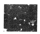
- 2 is an SEM image of a cross section of a conventional RTB-based permanent magnet having a thick grain boundary.
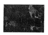
- 2 is an SEM image of a cross section of a conventional RTB-based permanent magnet having a thin grain boundary. It is a schematic diagram explaining the method of measuring the thickness of a two-particle grain boundary.
- the RTB-based permanent magnet according to the present embodiment includes a main phase particle composed of an R 2 T 14 B crystal and a two-particle grain boundary existing between two adjacent main phase particles.
- R is one or more rare earth elements that require Nd or Pr
- T is one or more iron group elements that require Fe or Fe and Co
- B is boron.
- the rare earth element contained as R refers to Sc, Y, and a lanthanoid element belonging to Group 3 of the long periodic table.
- the iron group elements refer to Fe, Co, and Ni.
- the particle size of the main phase particles composed of R 2 T 14 B crystals is arbitrary. Usually, it is 1 ⁇ m or more and 10 ⁇ m or less.
- the area ratio of R 6 T 13 M compounds in an arbitrary cross section is not more than 0.50%. It may also be the area ratio of R 6 T 13 M compound 0.45% or less, preferably not more than 0.15%. Further, the area ratio of the R 6 T 13 M compound may be 0%. That, R-T-B based permanent magnet may not include the R 6 T 13 M compound. Further, the R 6 T 13 M compound is a compound having a La 6 Co 11 Ga type 3 crystal structure and having an atomic number ratio of R: T: M of about 6: 13: 1.
- Area ratio of R 6 T 13 M compounds in the R-T-B-based permanent magnets can be measured using a scanning electron microscope (SEM).
- SEM scanning electron microscope
- the RTB permanent magnet is cut at an arbitrary cross section and polished.
- the size of the observation range is determined so that at least about 200, preferably about 250, main phase particles can be seen in the cross section.
- the observation magnification is 1000 times or more and 5000 times or less.
- the cross section is observed by SEM.
- the R 6 T 13 M compound is specified by the reflected electron image obtained by using SEM, and the area ratio of the R 6 T 13 M compound is calculated. Specifically analyzed by image analysis software backscattered electron image obtained using a SEM, finding the area ratio of R 6 T 13 M compound.
- the part containing many elements having a small atomic number is displayed darkly, and the part containing many elements having a large atomic number is displayed brightly.
- a portion of the grain boundary containing a large amount of rare earth elements, for example, the R-rich phase described later is displayed brightly.
- the main phase particles composed of R 2 T 14 B crystals are displayed dark.
- the R 6 T 13 M compound is displayed with a brightness intermediate between the brightness of the main phase particles and the brightness of the R rich phase.
- whether or not the compound whose brightness in the reflected electron image is between the brightness of the R-rich phase and the brightness of the main phase particles is the R 6 T 13 M compound can be determined by performing various measurement methods.
- Examples of various measurement methods include, for example, SEM (scanning electron microscope) -EDS (energy dispersive X-ray spectroscopy), TEM (transmission electron microscope) -SAED (limited field electron beam diffraction) -EDS (energy dispersive type). X-ray spectroscopy) or EPMA (wavelength dispersive energy spectroscopy) can be mentioned.
- the RTB-based permanent magnet according to the present embodiment has an average thickness of two particle boundaries of 5 nm or more and 50 nm or less. Further, it may be 7 nm or more and 33 nm or less.
- the average thickness of the two-particle boundary can be measured using a high-resolution transmission electron microscope (HRTEM).
- the average thickness of the two-particle boundary is the average value of the measurement results at at least 60 points.
- FIG. 4 is a schematic view specifically showing a method for measuring the thickness of two-particle boundary in the present embodiment.
- a two-particle grain boundary 2 and a grain boundary triple point 3 are formed between a plurality of adjacent main phase crystal particles 1.
- the two-particle grain boundary 2 for which the thickness is to be measured is determined.
- the boundaries 6a and 6b between the two-particle grain boundary 2 and the grain boundary triple point 3 connected to the two-particle grain boundary 2 are determined.
- the boundaries 6a and 6b do not need to be determined accurately and may be determined visually from the HRTEM image. This is because the thickness of the two-particle boundary is not measured in the vicinity of the boundaries 6a and 6b.
- the area ratio of R 6 T 13 M compound is not more than 0.50%, and the average thickness of the second grain grain boundary is 5nm or more 50nm or less.
- area ratio of R 6 T 13 M compound is not more than 0.50%, secondary phase other than the main phase grains in the R-T-B-based permanent magnet is reduced.
- the residual magnetic flux density is improved.
- the coercive force is improved by increasing the average thickness of the two-particle boundary. If the average thickness of the two-particle boundary is too thick, the coercive force is likely to be further improved.
- the volume fraction of the two-particle boundary phase in the entire RTB-based permanent magnet becomes large, and the residual magnetic flux density tends to decrease.
- the RTB-based permanent magnet according to the present embodiment has small grain boundary triple points and subphases and has two grain boundaries. Can be confirmed.
- the conventional RTB-based permanent magnet shown in FIG. 2 it can be clearly confirmed from the SEM image that two grain boundaries exist, but the size of the grain boundary triple points and subphases is large. .. As a result, the residual magnetic flux density tends to decrease.
- the structure shown in FIG. 2 is often found in RTB-based permanent magnets in which the B content is as small as less than 0.95% by mass and the Ga content is as large as 0.20% by mass or more. Is.
- the two-particle grain boundary is thin, and it cannot be clearly confirmed from the SEM image that the two-particle grain boundary exists. As a result, the coercive force tends to decrease.
- the structure shown in FIG. 3 is often found in RTB permanent magnets having a large B content of 0.95% by mass or more and a small Ga content of less than 0.20% by mass. Is. Further, even if the R of the RTB-based permanent magnet shown in FIG. 3 is simply increased, the two-particle grain boundary does not easily become thick, and the size of the grain boundary triple point and the subphase tends to increase.
- the RTB-based permanent magnet according to this embodiment contains at least Nd or Pr as R. More preferably, it contains Nd. Further, the RTB-based permanent magnet according to the present embodiment may contain a heavy rare earth element as R. However, an RTB-based permanent magnet having high magnetic properties can be obtained even if the content of heavy rare earth elements is small. Specifically, the content of the heavy rare earth element may be 1.0% by mass or less (including 0% by mass). The content of the heavy rare earth element is preferably 0.50% by mass or less, and more preferably 0.10% by mass or less. This is because the RTB-based permanent magnet according to the present embodiment can obtain a high coercive force even if the content of the heavy rare earth element is reduced, and the content of the heavy rare earth element can be reduced.
- the content of R is not particularly limited, but may be 25% by mass or more and 35% by mass or less.
- the content of R is 25% by weight or more, the main phase grains of the R-T-B-based permanent magnet R 2 T 14 B easily generated sufficiently performed crystals, having a soft magnetic alpha-Fe, etc. Precipitation is suppressed, and deterioration of magnetic properties can be easily suppressed.
- the R content is 35% by mass or less, the residual magnetic flux density of the RTB-based permanent magnet tends to improve.
- the content of R may be 29.0% by mass or more and 32.5% by mass or less.
- the content of B in the RTB-based permanent magnet according to the present embodiment may be 0.50% by mass or more and 1.5% by mass or less.
- the content of B is preferably 0.85% by mass or more and 1.05% by mass or less.
- the area ratio of the subphase containing the triple point of grain boundaries and carbon tends to increase.
- the area ratio of the R 6 T 13 M compound tends to increase.
- the residual magnetic flux density tends to decrease.
- Tb is likely to be accumulated at the grain boundary. As a result, it becomes difficult to efficiently obtain the effect of increasing the coercive force due to the diffusion of the grain boundaries of Tb, and the residual magnetic flux density tends to decrease.
- T may be Fe alone, or a part of Fe may be replaced with Co.
- Ni may be contained as T.
- the Fe content in the RTB-based permanent magnet according to the present embodiment may be a substantial balance when unavoidable impurities are removed in the RTB-based permanent magnet.
- the content of Co is preferably 0% by mass or more and 4% by mass or less, and may be 0.20% by mass or more and 3.0% by mass or less. When the Co content is 0.20% by mass or less, the corrosion resistance tends to decrease. Even if the Co content exceeds 3.0% by mass, it becomes difficult to improve the characteristics such as corrosion resistance as compared with the case where the Co content is 3.0% by mass or less. And the cost is high.
- the RTB-based permanent magnet according to the present embodiment may contain Ga, Al, Cu and / or Si as the element M other than R, T and B. Further, the RTB-based permanent magnet preferably contains at least Al and / or Cu.
- the content of each element is arbitrary.
- the total content of M may be 0.50% by mass or less, or 0.30% by mass or less. Further, the total content of M may be 0% by mass, preferably 0.10% by mass or more.
- the Ga content is preferably 0.20% by mass or less.
- the M content is high, the area ratio of the grain boundary triple point and the sub-phase containing carbon tends to increase, and the area ratio of the R 6 T 13 M compound tends to increase. As a result, the residual magnetic flux density tends to decrease. Further, when the grain boundary diffusion of heavy rare earth elements, particularly the grain boundary diffusion of Tb is performed, Tb is likely to be accumulated at the grain boundary. As a result, it becomes difficult to efficiently obtain the effect of increasing the coercive force due to the diffusion of the grain boundaries of Tb, and the residual magnetic flux density tends to decrease.
- the content of M is small, the change in magnetic properties (particularly Hcj and squareness) with respect to changes in manufacturing conditions becomes large. As a result, the variation in magnetic characteristics during mass production becomes large. That is, the manufacturing stability is lowered.
- the RTB-based permanent magnet according to the present embodiment may contain Zr as an element other than the above R, T, B and M.
- Zr is contained, the Zr content is preferably 1.5% by mass or less, assuming that the entire RTB-based permanent magnet is 100% by mass. Since the RTB-based permanent magnet contains Zr, abnormal growth of crystal grains during sintering during the manufacturing process can be suppressed.
- the structure of the sintered body (sintered magnet) obtained by sintering can be made into a uniform and fine structure, and the magnetic properties can be improved.
- the content of Zr may be 0.03 to 0.25% by mass.
- the RTB-based permanent magnet according to the present embodiment may contain Ti, Ta, Nb, V or Cr as elements other than the above R, T, B and M.
- the content of these elements may be 1.0% by mass or less, assuming that the entire RTB-based permanent magnet is 100% by mass.
- the RTB-based permanent magnet according to the present embodiment may further contain carbon as an element other than the above-mentioned elements.
- the amount of carbon is arbitrary, but it is preferably relatively small.
- the total amount of RTB-based permanent magnets is 100% by mass and the carbon content is 0.080% by mass or less.
- There is no particular lower limit on the amount of carbon but for example, it may be 0.020% by mass or more, and preferably 0.040% by mass or more.
- the Curie point can be raised and the temperature characteristics can be improved.
- the ratio of the R-rich phase that contributes to the formation of two-particle boundaries increases.
- the content of the R 6 T 13 M compound is small, the formation of thick two-particle boundaries is promoted.
- the grain boundary diffusion of heavy rare earth elements, particularly the grain boundary diffusion of Tb is performed, it becomes easy to suppress the accumulation of Tb at the grain boundary. Then, it becomes easy to efficiently obtain the effect of increasing the coercive force due to the diffusion of the grain boundaries of Tb, and it becomes easy to maintain the residual magnetic flux density.
- the RTB permanent magnet contains unavoidable impurities such as Mn, Ca, Cl, S, F, O, and N as other elements in an amount of 0.001% by mass or more and 1.0% by mass or less. May be good.
- the method for manufacturing an RTB-based permanent magnet according to the present embodiment includes at least a step of forming a molded body and a step of sintering the molded body to which metal is attached.
- the raw material powder can be produced by a known method.
- the RTB-based permanent magnets are manufactured by a one-alloy method using one kind of raw material alloy mainly composed of R 2 T 14 B phase, but by a two-alloy method using two kinds of raw material alloys. It may be manufactured.
- a raw material metal corresponding to the composition of the raw material alloy according to the present embodiment is prepared, and a raw material alloy corresponding to the present embodiment is produced from the raw material metal.
- a raw material alloy can be produced by a strip casting method.
- the crushing step may be carried out in two steps or in one step.
- the crushing method is not particularly limited. For example, it is carried out by a method using various crushers.
- the pulverization step can be carried out in two stages, a coarse pulverization step and a fine pulverization step, and the coarse pulverization step can be, for example, a hydrogen pulverization treatment.
- dehydrogenation can be performed in an Ar gas atmosphere at 400 ° C. or higher and 650 ° C. or lower, and 0.5 hours or longer and 2 hours or shorter.
- the fine pulverization step can be performed by adding a lubricant such as oleic acid amide or zinc stearate to the powder after coarse pulverization, and then using, for example, a jet mill or a wet attritor.
- a lubricant such as oleic acid amide or zinc stearate
- the particle size of the obtained finely pulverized powder (raw material powder) is not particularly limited.
- fine pulverization can be performed so that the pulverized powder (raw material powder) having a particle size (D50) of 1 ⁇ m or more and 10 ⁇ m or less is obtained.
- the amount of the above-mentioned lubricant added may be reduced in order to reduce the amount of carbon contained in the RTB permanent magnet, but it does not have to be reduced. The reason will be described later.
- the finely crushed powder (raw material powder) obtained in the crushing step is molded into a predetermined shape.
- the molding method is not particularly limited, but in the present embodiment, the finely pulverized powder (raw material powder) is filled in the mold and pressurized in a magnetic field.
- the pressurization during molding is preferably performed at 30 MPa or more and 300 MPa or less.
- the magnetic field to be applied is preferably 950 kA / m or more and 1600 kA / m or less.
- the applied magnetic field is not limited to the static magnetic field, and may be a pulsed magnetic field. Moreover, the static magnetic field and the pulsed magnetic field can be used together.
- the shape of the molded product obtained by molding the finely pulverized powder (raw material powder) is not particularly limited, and depends on the desired shape of the RTB-based permanent magnet such as a rectangular parallelepiped, a flat plate, or a columnar shape. Can have any shape.
- the sintering step is a step of sintering a molded product in a vacuum or an inert gas atmosphere to obtain a sintered body.
- the sintering temperature needs to be adjusted according to various conditions such as composition, pulverization method, difference in particle size and particle size distribution, etc. Sintering is performed by heating at ° C. or lower for 1 hour or more and 10 hours or lower. As a result, a high-density sintered body (permanent magnet) can be obtained.
- a metal is attached to the molded body prior to sintering.
- the type of metal is that the standard production Gibbs energy for producing metal carbides from the metal is higher than the standard production Gibbs energy for producing carbides of the rare earth element (for example, Nd) mainly contained in the sintered body. Also choose to be low.
- the metal is preferably a pure metal, and one kind of pure metal may be used or two or more kinds of pure metals may be used.
- the rare earth element mainly contained in the sintered body refers to the rare earth element contained most in the sintered body.
- Examples of the metal to be attached to the molded body include Zr, Ti, Ta, Nb, V and Cr. In particular, it is preferable to use Zr.
- the method of attaching the metal is arbitrary. For example, a method of placing a molded body on the metal powder, a method of sprinkling the metal powder on the molded body, a method of burying the molded body in the metal powder, and a method of placing the molded body on the metal plate. , A method of placing the metal plate on the molded body, a method of wrapping the molded body with the metal foil, a method of constructing the sintered tray itself with the metal, a method of placing the molded body on the metal net, a molding process.
- the effect of reducing the carbon content ratio by adhering the metal to the molded body becomes greater as it is attached to a surface having a large area among each surface of the molded body.
- the metal foil may not come into contact with the molded body, and the contact area may become smaller.
- the carbon inside the molded body moves to the surface of the rare earth permanent magnet and reacts with the metal to become carbide.
- the metal hardly penetrates into the magnet and stays on the magnet surface. As a result, the carbon content in the rare earth permanent magnets can be reduced.
- the carbon content is reduced by this method, it is easier to preferably maintain the residual magnetic flux density as compared with the case where the carbon content is reduced by reducing the lubricant. This is because when the amount of the lubricant is reduced, the degree of orientation tends to decrease in the molding process, and the residual magnetic flux density of the finally obtained magnet tends to decrease. Therefore, it is preferable to determine the amount of the lubricant added in consideration of the coercive force and the residual magnetic flux density of the target magnet.
- the aging treatment step is performed by heating the sintered body (permanent magnet) after the sintering step at a temperature lower than the sintering temperature.
- the temperature and time of the aging treatment are not particularly limited, but can be carried out, for example, at 450 ° C. or higher and 900 ° C. or lower for 0.2 hours or longer and 3 hours or shorter.
- the aging treatment step may be omitted.
- the aging treatment step may be performed in one step or in two steps.
- the first step is set to 700 ° C. or higher and 900 ° C. or lower for 0.2 hours or more and 3 hours or less
- the second step is set to 450 ° C. or higher and 700 ° C. or lower for 0.2 hours or more and 3 hours or less. May be good.
- the first step and the second step may be continuously performed, or after the first step, the first step may be cooled to near room temperature and then reheated to perform the second step.
- the metal may be removed by polishing the entire surface of the RTB-based sintered magnet or the surface to which the metal is attached by 50 ⁇ m or more.
- the RTB-based permanent magnet of the present invention is not limited to the above embodiment.
- the RTB-based permanent magnet of the present invention can be deformed and combined in various ways without departing from the gist thereof.
- a magnet obtained by cutting and dividing the RTB-based permanent magnet according to the present embodiment can be used.
- the RTB-based permanent magnet according to the present embodiment is suitably used for applications such as motors, compressors, magnetic sensors, and speakers.
- the RTB-based permanent magnets according to the present embodiment may be used alone, or two or more RTB-based permanent magnets may be combined and used as necessary. There are no particular restrictions on the joining method. For example, there are a method of mechanically bonding and a method of bonding with a resin mold.
- a large RTB permanent magnet can be easily manufactured.
- a magnet in which two or more RTB permanent magnets are coupled is preferably used in applications where a particularly large RTB permanent magnet is required, for example, an IPM motor, a wind power generator, a large motor, or the like. ..
- Example 1 Permanent magnet manufacturing process
- Nd As a raw material metal, Nd, electrolytic iron, and a low-carbon ferroborone alloy were prepared. Further, Ga, Al, Cu, Co and Zr were prepared in the form of a pure metal or an alloy with Fe.
- a raw material alloy was prepared from the raw material metal by a strip casting method so that the composition of the raw material powder obtained by fine pulverization described later was the composition shown in Tables 1 and 2.
- the content of unavoidable impurities and the like in the raw material alloy was set to 1% by mass or less.
- the alloy thickness of the raw material alloy was 0.2 mm to 0.6 mm.
- 0.10% oleic acid amide by mass was added as a lubricant to the powder of the raw material alloy after hydrogen pulverization and mixed.
- fine pulverization was performed in a nitrogen stream using a collision plate type jet mill device to obtain fine powder (raw material powder) having an average particle size of about 4 ⁇ m.
- the average particle size is the average particle size D50 measured by a laser diffraction type particle size distribution meter.
- H, Si, Ca, La, Ce, Cr, etc. may be detected as unavoidable impurities.
- Si is mainly mixed from the ferrobolon raw material and the crucible when the alloy is melted.
- Ca, La, and Ce are mixed from rare earth raw materials.
- Cr may be mixed from electrolytic iron.
- the applied magnetic field at this time is a static magnetic field of 1200 kA / m.
- the pressing force during molding was 120 MPa.
- the magnetic field application direction and the pressurization direction were made orthogonal to each other.
- the density of the molded product was measured at this point, the density of all the molded products was in the range of 4.10 Mg / m 3 or more and 4.25 Mg / m 3 or less.
- the form of the metal was powder
- 3% by mass of the metal powder was brought into contact with the molded product having a mass of 100% by mass. Specifically, the metal powder was brought into contact with each of the two surfaces having the widest area of the molded product, that is, the two 20 mm ⁇ 20 mm surfaces by 1.5% by mass. In addition, the metal powder was made to adhere uniformly on each surface.
- a metal powder in which Zr and Ti were mixed so as to have a weight ratio of 66:34 was brought into contact with each other.
- a metal plate with a thickness of 1 mm was brought into contact. Specifically, the metal plate was brought into contact with the entire two surfaces having the widest area of the molded product.
- a metal foil having a thickness of 10 ⁇ m was brought into contact with the metal. Specifically, the entire molded body was wrapped with metal foil so that the metal foil was in contact with the entire surface of the molded body.
- the molded product was sintered to obtain a permanent magnet.
- the sintering conditions were 1060 ° C. for 4 hours.
- the sintering atmosphere was in vacuum.
- the sintering density was in the range of 7.50 Mg / m 3 or more and 7.55 Mg / m 3 or less.
- the metal attached from the obtained permanent magnet, the residue generated by sintering, and the surface irregularities were removed. Specifically, the entire surface of the permanent magnet was polished by 50 ⁇ m.
- the composition of the obtained permanent magnet was evaluated by fluorescent X-ray analysis.
- the B content was evaluated by ICP, and the carbon content was evaluated by the combustion in oxygen stream-infrared absorption method.
- the composition of the raw material alloy and the composition of the obtained permanent magnet were substantially the same except for the amount of carbon. That is, almost all of the attached metal was removed by the above polishing, and it was not substantially contained in the permanent magnet.
- the amount of carbon is shown in Table 1.
- the magnetic characteristics (residual magnetic flux density Br and coercive force Hcj) of the obtained permanent magnets were evaluated with a BH tracer.
- the coercive force was set to 1230 kA / m or more.
- the residual magnetic flux density was good at 1400 mT or more.
- the obtained permanent magnets were measured the area ratio of R 6 T 13 M compound.
- the cross section of the permanent magnet was observed by SEM, it is calculate the area ratio of R 6 T 13 M compound.
- the observation range was 0.25 mm ⁇ 0.25 mm. It was also confirmed that the observation range contained at least 1200 main phase particles.
- the results are shown in Table 1.
- Comparative Examples 1 to 4 Comparative Examples 1 to 4, which are 1.00% by mass in which the B content is relatively large and do not contain Ga, have a large carbon content. Then, as shown in FIG. 3, the average thickness of the two-particle boundary became low. As a result, Hcj decreased as compared with Examples. Even if the amount of R is increased from Comparative Examples 1 and 3, the area ratio of the triple point of the grain boundary tends to increase, and it is difficult to set the average thickness of the two grain boundaries to 5 nm or more.
- Comparative Example 2 having a relatively low B content of 0.90% by mass and a relatively high Ga content of 0.20% by mass had a large carbon content. Then, the area ratio of the triple point of the grain boundary increased, and the area ratio of the sub-phase containing carbon and the R 6 T 13 M phase increased. As a result, Br decreased as compared with Examples.
- Comparative Example 4 having a B content of 0.95% by mass and a Ga content of 0.10% by mass has a large carbon content and an average thickness of two grain boundaries. It became low. As a result, Hcj decreased as compared with Examples.
- Example 2 In Experimental Example 2, the composition of the raw material powder was set to Composition 1 in Table 2, and the same procedure as in Experimental Example 1 was carried out except that the type of metal element to be brought into contact with the molded product during sintering was changed. The results are shown in Table 3.
- Example 3 In Experimental Example 3, the same procedure as in Experimental Example 1 was carried out except that the composition of the raw material powder was the composition shown in Table 4. The results are shown in Table 4.
- Example 36 in which the content of B was relatively high, Br and Hcj were reduced as compared with Example 1 carried out under the same conditions except for the content of B. This is because when the content of B is high, a secondary phase such as a boride of a rare earth element is likely to occur.
- Example 4 In Experimental Example 4, the same procedure as in Example 1 was carried out except that the amount of the metal powder was changed. The results are shown in Table 5.
- Comparative Example 51 the average thickness of the two-particle boundary became too thick. As a result, Br decreased. Further, in Comparative Example 51, as the amount of carbon decreased, the area ratio of the R 6 T 13 M compound increased, and the R 2 Fe 17 compound was generated at the grain boundaries. As a result, Hcj was also reduced as compared with Example 1 and Example 53.
Landscapes
- Engineering & Computer Science (AREA)
- Power Engineering (AREA)
- Chemical & Material Sciences (AREA)
- Inorganic Chemistry (AREA)
- Crystallography & Structural Chemistry (AREA)
- Mechanical Engineering (AREA)
- Manufacturing & Machinery (AREA)
- Organic Chemistry (AREA)
- Metallurgy (AREA)
- Materials Engineering (AREA)
- Powder Metallurgy (AREA)
- Hard Magnetic Materials (AREA)
- Manufacturing Cores, Coils, And Magnets (AREA)
Abstract
【課題】 磁気特性を向上させたR-T-B系永久磁石を得る。 【解決手段】 RはNdまたはPrを必須とする1種以上の希土類元素、TはFeを必須とする1種以上の鉄族元素、Bはホウ素であり、Ga、Al、CuおよびSiのうち少なくとも1種以上であるMを含むR-T-B系永久磁石である。R-T-B系永久磁石が、R2T14B結晶からなる主相粒子と、隣接する二つの主相粒子の間に存在する二粒子粒界と、を含む。二粒子粒界の平均厚みは5nm以上50nm以下である。任意の断面におけるR6T13M化合物の面積比率が0.50%以下(0%を含む)である。
Description
本発明は、R-T-B系永久磁石およびその製造方法に関する。
R-T-B系永久磁石は、優れた磁気特性を有することが知られている。そして、さらに磁気特性を向上させたR-T-B系永久磁石の開発が行われている。
特許文献1には、各成分の含有量を特定の範囲内とし、特にBの含有量を低くすることで磁気特性を向上させた焼結磁石が記載されている。
特許文献2には、特にRの含有量、Bの含有量、Gaの含有量を特定の範囲内に制御することで高い保磁力を有するR-T-B系焼結磁石が記載されている。
特許文献3には、粒界中にR-Co-Cu-N濃縮部等の濃縮部が存在することで優れた耐食性と良好な磁気特性とを併せ持つR-T-B系焼結磁石が記載されている。
しかし、現在では、多くの用途で磁性部品の一層の小型化、軽量化、高効率化が求められている。そのため、R-T-B系焼結磁石などのR-T-B系永久磁石においてさらなる磁気特性の向上が求められている。
本発明は、磁気特性を向上させたR-T-B系永久磁石を得ることを目的とする。
上記の目的を達成するために、本発明に係るR-T-B系永久磁石は、
RはNdまたはPrを必須とする1種以上の希土類元素、TはFeを必須とする1種以上の鉄族元素、Bはホウ素であり、Ga、Al、CuおよびSiのうち少なくとも1種以上であるMを含むR-T-B系永久磁石であって、
前記R-T-B系永久磁石が、R2T14B結晶からなる主相粒子と、隣接する二つの主相粒子の間に存在する二粒子粒界と、を含み、
前記二粒子粒界の平均厚みは5nm以上50nm以下であり、
任意の断面におけるR6T13M化合物の面積比率が0.50%以下(0%を含む)である。
RはNdまたはPrを必須とする1種以上の希土類元素、TはFeを必須とする1種以上の鉄族元素、Bはホウ素であり、Ga、Al、CuおよびSiのうち少なくとも1種以上であるMを含むR-T-B系永久磁石であって、
前記R-T-B系永久磁石が、R2T14B結晶からなる主相粒子と、隣接する二つの主相粒子の間に存在する二粒子粒界と、を含み、
前記二粒子粒界の平均厚みは5nm以上50nm以下であり、
任意の断面におけるR6T13M化合物の面積比率が0.50%以下(0%を含む)である。
本発明に係るR-T-B系永久磁石は、上記の特徴を有することにより、磁気特性を向上させたR-T-B系永久磁石となる。
上記の目的を達成するために、本発明に係るR-T-B系永久磁石の製造方法は、
RはNdまたはPrを必須とする1種以上の希土類元素、TはFeを必須とする1種以上の鉄族元素、Bはホウ素であり、
R2T14B結晶からなる主相粒子と、隣接する二つの主相粒子の間に存在する二粒子粒界と、を含むR-T-B系永久磁石の製造方法であって、
成形体を形成する工程と、
金属が付着した成形体を焼結する工程と、を含み、
前記金属から金属炭化物を生成するための標準生成ギブスエネルギーが、Rとして前記成形体中に主に含まれる希土類元素から当該希土類元素の炭化物を生成するための標準生成ギブスエネルギーよりも低い。
RはNdまたはPrを必須とする1種以上の希土類元素、TはFeを必須とする1種以上の鉄族元素、Bはホウ素であり、
R2T14B結晶からなる主相粒子と、隣接する二つの主相粒子の間に存在する二粒子粒界と、を含むR-T-B系永久磁石の製造方法であって、
成形体を形成する工程と、
金属が付着した成形体を焼結する工程と、を含み、
前記金属から金属炭化物を生成するための標準生成ギブスエネルギーが、Rとして前記成形体中に主に含まれる希土類元素から当該希土類元素の炭化物を生成するための標準生成ギブスエネルギーよりも低い。
上記の製造方法により得られるR-T-B系永久磁石は、磁気特性を向上させたR-T-B系永久磁石となる。
前記金属がZr、Ti、Ta、Nb、VおよびCrのうち少なくとも1種以上であってもよい。
前記金属が粉体であってもよい。
前記金属が板状であってもよい。
前記金属が箔状であってもよい。
以下、本発明を、具体的な実施形態に基づき説明する。
<R-T-B系永久磁石>
本実施形態に係るR-T-B系永久磁石は、R2T14B結晶からなる主相粒子と、隣接する二つの主相粒子の間に存在する二粒子粒界と、を含む。RはNdまたはPrを必須とする1種以上の希土類元素、TはFeまたはFeおよびCoを必須とする1種以上の鉄族元素、Bはホウ素である。なお、Rとして含まれる希土類元素とは、長周期型周期表の第3族に属するScとYとランタノイド元素とのことをいう。鉄族元素とは、Fe,Co,Niのことをいう。なお、R2T14B結晶からなる主相粒子の粒径は任意である。通常は、1μm以上10μm以下である。
本実施形態に係るR-T-B系永久磁石は、R2T14B結晶からなる主相粒子と、隣接する二つの主相粒子の間に存在する二粒子粒界と、を含む。RはNdまたはPrを必須とする1種以上の希土類元素、TはFeまたはFeおよびCoを必須とする1種以上の鉄族元素、Bはホウ素である。なお、Rとして含まれる希土類元素とは、長周期型周期表の第3族に属するScとYとランタノイド元素とのことをいう。鉄族元素とは、Fe,Co,Niのことをいう。なお、R2T14B結晶からなる主相粒子の粒径は任意である。通常は、1μm以上10μm以下である。
本実施形態に係るR-T-B系永久磁石は、任意の断面におけるR6T13M化合物の面積比率が0.50%以下である。R6T13M化合物の面積比率が0.45%以下であってもよく、0.15%以下であることが好ましい。また、R6T13M化合物の面積比率が0%であってもよい。すなわち、R-T-B系永久磁石がR6T13M化合物を含まなくてもよい。また、R6T13M化合物は、La6Co11Ga3型結晶構造を有し、R:T:Mが原子数比で概ね6:13:1である化合物のことである。
R-T-B系永久磁石におけるR6T13M化合物の面積比率は、例えば走査型電子顕微鏡(SEM)を用いて測定することができる。まず、R-T-B系永久磁石を任意の断面で切断し、研磨する。そして、当該断面において少なくとも200個程度、好ましくは250個程度の主相粒子が見えるように観察範囲の大きさを決定する。また、観察倍率は1000倍以上5000倍以下とする。そして、当該断面をSEMで観察する。そして、SEMを用いて得られる反射電子像にてR6T13M化合物を特定し、R6T13M化合物の面積比率を算出する。具体的にはSEMを用いて得られる反射電子像を画像解析ソフトにより解析し、R6T13M化合物の面積比率を求める。一般的に、反射電子像は、原子番号の小さな元素が多く含まれる部分は暗く表示され、原子番号の大きな元素が多く含まれる部分は明るく表示される。例えば、粒界のうち希土類元素を多く含む部分、例えば後述するRリッチ相は明るく表示される。また、R2T14B結晶からなる主相粒子は暗く表示される。そして、R6T13M化合物は主相粒子の明るさとRリッチ相の明るさとの中間くらいの明るさで表示される。また、反射電子像における明るさがRリッチ相の明るさと主相粒子の明るさとの中間である化合物がR6T13M化合物か否かは、様々な測定法を実施することにより各化合物を同定することによって確認することができる。様々な測定法の例としては、例えば、SEM(走査電子顕微鏡)-EDS(エネルギー分散型X線分光法)、TEM(透過電子顕微鏡)-SAED(制限視野電子線回折)-EDS(エネルギー分散型X線分光法)、またはEPMA(波長分散型エネルギー分光法)が挙げられる。
上記の解析をR-T-B系永久磁石の断面における異なる5視野の反射電子像についてそれぞれ行い、各反射電子像におけるR6T13M化合物の面積比率を算出する。その平均値をR6T13M化合物の面積比率とする。
本実施形態に係るR-T-B系永久磁石は、二粒子粒界の平均厚みが5nm以上50nm以下である。また、7nm以上33nm以下であってもよい。また、二粒子粒界の平均厚みは、高分解能透過型電子顕微鏡(HRTEM)を用いて測定可能である。
ここで、二粒子粒界の平均厚みは、少なくとも60箇所での測定結果の平均値とする。図4は本実施形態における二粒子粒界の厚みを測定する方法を具体的に示す模式図である。隣接する複数の主相結晶粒子1の間には、二粒子粒界2および粒界三重点3が形成されている。まず、厚みを測定する二粒子粒界2を決定する。そして、二粒子粒界2と当該二粒子粒界2に繋がっている粒界三重点3との境界6a、6bを決定する。境界6a、6bは、正確に決定する必要はなく、HRTEM画像から目視にて決定してよい。境界6a、6bの近傍では二粒子粒界の厚みを測定しないためである。
境界6a、6bを決定した後に、境界6aと境界6bとの間を4等分し、3つの等分線を引く。この3つの等分線の位置を二粒子粒界の厚みの測定箇所とする。すなわち、一つの二粒子粒界2について、3箇所で厚みを測定することになる。この測定を、少なくとも20個の二粒子粒界2について行い、得られた二粒子粒界の厚みを平均することで二粒子粒界の平均厚みが得られる。
本実施形態に係るR-T-B系永久磁石は、R6T13M化合物の面積比率が0.50%以下であり、かつ、二粒子粒界の平均厚みが5nm以上50nm以下である。R6T13M化合物の面積比率が0.50%以下であることにより、R-T-B系永久磁石における主相粒子以外の副相が少なくなる。その結果、残留磁束密度が向上する。また、二粒子粒界の平均厚みが厚いことにより、保磁力が向上する。なお、二粒子粒界の平均厚みが厚すぎる場合には保磁力がさらに向上しやすくなる。しかし、R-T-B系永久磁石全体に占める二粒子粒界相の体積分率が大きくなり、残留磁束密度が低下しやすくなる。
本実施形態に係るR-T-B系永久磁石は、図1に示すように、粒界三重点や副相の大きさが小さく、かつ、二粒子粒界が存在することがSEM画像で明確に確認できる。
これに対し、図2に示す従来のR-T-B系永久磁石では、二粒子粒界が存在することがSEM画像で明確に確認できるが、粒界三重点や副相の大きさが大きい。この結果、残留磁束密度が低下しやすい。なお、図2に示す構造は、特にBの含有量が0.95質量%未満と小さく、Gaの含有量が0.20質量%以上と大きいR-T-B系永久磁石によく見られる構造である。
また、図3に示す従来のR-T-B系永久磁石では、二粒子粒界が細く、二粒子粒界が存在することがSEM画像で明確に確認できない。この結果、保磁力が低下しやすい。なお、図3に示す構造は、特にBの含有量が0.95質量%以上と大きく、Gaの含有量が0.20質量%未満と小さいR-T-B系永久磁石によく見られる構造である。また、単に図3に示すR-T-B系永久磁石のRを増やしても、二粒子粒界は太くなりにくく、粒界三重点や副相の大きさが大きくなりやすい。
本実施形態に係るR-T-B系永久磁石はRとして少なくともNdまたはPrを含む。さらに好ましくはNdを含む。また、本実施形態に係るR-T-B系永久磁石はRとして重希土類元素を含有してもよい。しかし、重希土類元素の含有量が少なくても高い磁気特性を有するR-T-B系永久磁石が得られる。重希土類元素の含有量は、具体的には、1.0質量%以下(0質量%を含む)としてもよい。また、重希土類元素の含有量は、0.50質量%以下であることが好ましく、0.10質量%以下であることがさらに好ましい。本実施形態に係るR-T-B系永久磁石は、重希土類元素の含有量を低減しても高い保磁力を得ることができ、重希土類元素の含有量を削減できるためである。
Rの含有量には特に制限はないが、25質量%以上35質量%以下であってもよい。Rの含有量が25質量%以上であると、R-T-B系永久磁石の主相粒子となるR2T14B結晶の生成が十分に行われやすく、軟磁性を持つα-Feなどの析出を抑制し、磁気特性の低下を抑制しやすくなる。Rの含有量が35質量%以下であると、R-T-B系永久磁石の残留磁束密度が向上する傾向にある。Rの含有量は29.0質量%以上32.5質量%以下であってもよい。
本実施形態に係るR-T-B系永久磁石におけるBの含有量は、0.50質量%以上1.5質量%以下であってもよい。Bの含有量は0.85質量%以上1.05質量%以下であることが好ましい。Bの含有量が少ない場合には、粒界三重点や炭素を含む副相の面積割合が多くなりやすくなる。さらに、R6T13M化合物の面積比率も大きくなりやすくなる。その結果、残留磁束密度が低下しやすくなる。さらに、重希土類元素の粒界拡散、特にTbの粒界拡散を行う場合にはTbが粒界に集積しやすくなる。その結果、Tbの粒界拡散による保磁力上昇の効果を効率的に得にくくなり、残留磁束密度も低下しやすくなる。
Tは、Fe単独であってもよく、Feの一部がCoで置換されていてもよい。TとしてNiを含んでもよい。本実施形態に係るR-T-B系永久磁石におけるFeの含有量は、R-T-B系永久磁石において不可避的不純物を除いた場合の実質的な残部であってもよい。Coの含有量は0質量%以上4質量%以下であることが好ましく、0.20質量%以上3.0質量%以下であってもよい。Coの含有量が0.20質量%以下の場合には耐食性が低下しやすくなる。Coの含有量が3.0質量%を超えてもCoの含有量が3.0質量%以下の場合と比較して耐食性などの特性が向上しにくくなる。そして、コストが高くなる。
本実施形態に係るR-T-B系永久磁石は、R,TおよびB以外の元素Mとして、Ga,Al,Cuおよび/またはSiを含んでもよい。また、R-T-B系永久磁石は少なくともAlおよび/またはCuを含むことが好ましい。各元素の含有量は任意である。例えば、Mの合計含有量は0.50質量%以下であってもよく、0.30質量%以下であってもよい。さらに、Mの合計含有量は0質量%であってもよく、0.10質量%以上であることが好ましい。なお、Gaの含有量は0.20質量%以下であることが好ましい。
Mの含有量が多い場合には、粒界三重点や炭素を含む副相の面積割合が多くなりやすく、さらに、R6T13M化合物の面積比率も大きくなりやすくなる。その結果、残留磁束密度が低下しやすくなる。さらに、重希土類元素の粒界拡散、特にTbの粒界拡散を行う場合にはTbが粒界に集積しやすくなる。その結果、Tbの粒界拡散による保磁力上昇の効果を効率的に得にくくなり、残留磁束密度も低下しやすくなる。Mの含有量が少ない場合には、製造条件の変化に対する磁気特性(特にHcjおよび角型性)の変化が大きくなる。その結果、量産時における磁気特性のばらつきが大きくなる。すなわち、製造安定性が低下する。
本実施形態に係るR-T-B系永久磁石は、上記のR,T,BおよびM以外の元素として、Zrを含んでもよい。Zrを含む場合におけるZrの含有量は、R-T-B系永久磁石全体を100質量%として、1.5質量%以下であることが好ましい。R-T-B系永久磁石がZrを含むことにより、製造工程中の焼結時における結晶粒の異常成長を抑制することができる。焼結により得られる焼結体(焼結磁石)の組織を均一かつ微細な組織にすることができ、磁気特性を向上することができる。Zrの含有量は、0.03~0.25質量%であってもよい。また、本実施形態に係るR-T-B系永久磁石は、上記のR,T,BおよびM以外の元素として、Ti,Ta,Nb,VまたはCrを含んでもよい。これらの元素を含む場合におけるこれらの元素の含有量は、R-T-B系永久磁石全体を100質量%として、1.0質量%以下であってもよい。
本実施形態に係るR-T-B系永久磁石は、上記した元素以外の元素として、さらに炭素を含んでもよい。炭素量は任意であるが、比較的少ないことが好ましい。例えば、R-T-B系永久磁石全体を100質量%として、炭素量が0.080質量%以下であることが好ましい。炭素量の下限は特にないが、例えば0.020質量%以上としてもよく、0.040質量%以上とすることが好ましい。炭素量が少なくなると軟磁性相であるR2Fe17化合物が粒界に生成しやすくなり、Hcjが低下しやすくなる。
R-T-B系永久磁石の炭素量を比較的、少なくすることにより、キュリー点を上昇させ、温度特性を改善させることができる。また、粒界におけるRとCとが結合した副相の生成を抑制できる。その結果、二粒子粒界の形成に寄与するRリッチ相の比率が増加する。そして、R6T13M化合物の含有量が少なくても厚い二粒子粒界の形成が促進される。さらに、重希土類元素の粒界拡散、特にTbの粒界拡散を行う場合にはTbが粒界に集積することを抑制しやすくなる。そして、Tbの粒界拡散による保磁力上昇の効果を効率的に得やすくなり、残留磁束密度も維持しやすくなる。
R-T-B系永久磁石は、その他の元素としてMn,Ca,Cl,S,F,O,N等の不可避的不純物を、0.001質量%以上1.0質量%以下程度含んでいてもよい。
<R-T-B系永久磁石の製造方法>
次に、本実施形態に係るR-T-B系永久磁石の製造方法を説明する。
次に、本実施形態に係るR-T-B系永久磁石の製造方法を説明する。
本実施形態に係るR-T-B系永久磁石の製造方法は、少なくとも、成形体を形成する工程と、金属が付着した前記成形体を焼結する工程と、を含む。
以下、R-T-B系永久磁石の製造方法について詳しく説明していくが、特記しない事項については、公知の方法を用いればよい。
[原料粉末の準備工程]
原料粉末は、公知の方法により作製することができる。本実施形態では、主にR2T14B相からなる一種類の原料合金を用いる一合金法でR-T-B系永久磁石を製造するが、二種類の原料合金を用いる二合金法により製造してもよい。
原料粉末は、公知の方法により作製することができる。本実施形態では、主にR2T14B相からなる一種類の原料合金を用いる一合金法でR-T-B系永久磁石を製造するが、二種類の原料合金を用いる二合金法により製造してもよい。
まず、本実施形態に係る原料合金の組成に対応する原料金属を準備し、当該原料金属から本実施形態に対応する原料合金を作製する。原料合金の作製方法に特に制限はない。例えば、ストリップキャスト法にて原料合金を作製することができる。
原料合金を作製した後に、作製した原料合金を粉砕する(粉砕工程)。粉砕工程は、2段階で実施してもよく、1段階で実施してもよい。粉砕の方法には特に限定はない。例えば、各種粉砕機を用いる方法で実施される。例えば、粉砕工程を粗粉砕工程および微粉砕工程の2段階で実施し、粗粉砕工程は例えば水素粉砕処理を行うことが可能である。具体的には、原料合金に対して室温で水素を吸蔵させた後に、Arガス雰囲気下で400℃以上650℃以下、0.5時間以上2時間以下で脱水素を行うことが可能である。また、微粉砕工程は、粗粉砕後の粉末に対して、例えばオレイン酸アミド、ステアリン酸亜鉛などの潤滑剤を添加したのちに、例えばジェットミル、湿式アトライター等を用いて行うことができる。得られる微粉砕粉末(原料粉末)の粒径には特に制限はない。例えば、粒径(D50)が1μm以上10μm以下の微粉砕粉末(原料粉末)となるように微粉砕を行うことができる。
なお、R-T-B系永久磁石に含まれる炭素量を低減するために上記の潤滑剤の添加量を低減してもよいが、低減しなくてもよい。理由は後述する。
[成形工程]
成形工程では、粉砕工程により得られた微粉砕粉末(原料粉末)を所定の形状に成形する。成形方法には特に限定はないが、本実施形態では、微粉砕粉末(原料粉末)を金型内に充填し、磁場中で加圧する。
成形工程では、粉砕工程により得られた微粉砕粉末(原料粉末)を所定の形状に成形する。成形方法には特に限定はないが、本実施形態では、微粉砕粉末(原料粉末)を金型内に充填し、磁場中で加圧する。
成形時の加圧は、30MPa以上300MPa以下で行うことが好ましい。印加する磁場は、950kA/m以上1600kA/m以下であることが好ましい。印加する磁場は静磁場に限定されず、パルス状磁場とすることもできる。また、静磁場とパルス状磁場を併用することもできる。微粉砕粉末(原料粉末)を成形して得られる成形体の形状は特に限定されるものではなく、例えば直方体、平板状、柱状等、所望とするR-T-B系永久磁石の形状に応じて任意の形状とすることができる。
[焼結工程]
焼結工程は、成形体を真空または不活性ガス雰囲気中で焼結し、焼結体を得る工程である。焼結温度は、組成、粉砕方法、粒度と粒度分布の違い等、諸条件により調整する必要があるが、成形体に対して、例えば、真空中または不活性ガスの存在下、1000℃以上1200℃以下、1時間以上10時間以下で加熱する処理を行うことにより焼結する。これにより、高密度の焼結体(永久磁石)が得られる。
焼結工程は、成形体を真空または不活性ガス雰囲気中で焼結し、焼結体を得る工程である。焼結温度は、組成、粉砕方法、粒度と粒度分布の違い等、諸条件により調整する必要があるが、成形体に対して、例えば、真空中または不活性ガスの存在下、1000℃以上1200℃以下、1時間以上10時間以下で加熱する処理を行うことにより焼結する。これにより、高密度の焼結体(永久磁石)が得られる。
本実施形態におけるR-T-B系永久磁石の製造方法では、焼結に先立ち、成形体に金属を付着させる。金属の種類は、金属から金属炭化物を生成するための標準生成ギブスエネルギーが、焼結体に主に含まれる希土類元素(例えばNd)から当該希土類元素の炭化物を生成するための標準生成ギブスエネルギーよりも低くなるように選択する。また、金属は純金属であることが好ましく、1種類の純金属を用いてもよく2種類以上の純金属を用いてもよい。なお、焼結体に主に含まれる希土類元素とは、焼結体に最も多く含まれる希土類元素を指す。
成形体に付着させる金属としては、例えばZr、Ti、Ta、Nb、VおよびCrが挙げられる。特にZrを用いることが好ましい。
当該金属を付着させる方法は任意である。例えば、当該金属の粉末上に成形体を載せる方法、当該金属の粉末を成形体に振りかける方法、当該金属の粉末の中に成形体を埋める方法、当該金属の板の上に成形体を載せる方法、当該金属の板を成形体に載せる方法、当該金属の箔で成形体を包む方法、焼結トレー自体を当該金属で構成する方法、当該金属の網の上に成形体を載せる方法、成形工程において上下のパンチ面の一方もしくは両方に当該金属の粉末を配設して成形することで成形体の表面の少なくとも一部に当該金属からなる層を形成する方法、当該金属を塗布する方法、当該金属を蒸着する方法が挙げられる。さらに、上記の方法を組み合わせて用いてもよい。特に当該金属の粉末を用いる方法が好ましい。
なお、成形体に当該金属を付着させることにより炭素の含有割合を低減する効果は、成形体の各面のうち、面積の広い面に付着させるほど大きくなる。
また、当該金属の箔を用いる方法では、焼結前には全ての面に当該金属を接触させることが容易であり、接触面積を高めることが容易である。一方、焼結が進行するにつれ、成形体の体積が減少する。したがって、焼結が進行するにつれ、当該金属の箔が成形体と接触しなくなり、接触面積が小さくなってしまう場合がある。
当該金属を成形体に付着させた状態で焼結を行うことで、成形体内部の炭素が希土類永久磁石表面に移動して当該金属と反応し炭化物となる。一方、金属は磁石内部にほとんど侵入せず磁石表面に留まる。この結果、希土類永久磁石中の炭素の含有割合を低減することができる。
この方法で炭素量を低減する場合には、潤滑剤を低減することで炭素量を低減する場合と比較して残留磁束密度を好適に維持しやすい。潤滑剤を低減する場合には、成形工程において配向度が低下しやすく、最終的に得られる磁石の残留磁束密度が低下しやすくなるためである。したがって、目的とする磁石の保磁力および残留磁束密度を考慮して潤滑剤の添加量を決定することが好ましい。
[時効処理工程]
時効処理工程は、焼結工程後の焼結体(永久磁石)に対して、焼結温度よりも低い温度で加熱することにより行う。時効処理の温度および時間には特に制限はないが、例えば450℃以上900℃以下で0.2時間以上3時間以下、行うことができる。なお、この時効処理工程は省略してもよい。
時効処理工程は、焼結工程後の焼結体(永久磁石)に対して、焼結温度よりも低い温度で加熱することにより行う。時効処理の温度および時間には特に制限はないが、例えば450℃以上900℃以下で0.2時間以上3時間以下、行うことができる。なお、この時効処理工程は省略してもよい。
また、時効処理工程は1段階で行ってもよく、2段階で行ってもよい。2段階で行う場合には、例えば1段階目を700℃以上900℃以下で0.2時間以上3時間以下とし、2段階目を450℃以上700℃以下で0.2時間以上3時間以下としてもよい。また、1段階目と2段階目とを連続して行ってもよく、1段階目の後に一度室温近傍まで冷却してから再加熱して2段階目を行ってもよい。
時効処理前、または時効処理後に、成形体に付着させた金属を除去する。例えば、R-T-B系焼結磁石の全面、または、金属を付着させた面を50μm以上、研磨することで金属を除去してもよい。
以上、本発明のR-T-B系永久磁石の好適な実施形態について説明したが、本発明のR-T-B系永久磁石は上記の実施形態に制限されるものではない。本発明のR-T-B系永久磁石は、その要旨を逸脱しない範囲で様々な変形、種々の組み合わせが可能である。
さらに、本実施形態に係るR-T-B系永久磁石を切断、分割して得られる磁石を用いることができる。
具体的には、本実施形態に係るR-T-B系永久磁石は、モータ、コンプレッサー、磁気センサー、スピーカ等の用途に好適に用いられる。
また、本実施形態に係るR-T-B系永久磁石は、単独で用いてもよく、2個以上のR-T-B系永久磁石を必要に応じて結合させて用いてもよい。結合方法に特に制限はない。例えば、機械的に結合させる方法や樹脂モールドで結合させる方法がある。
2個以上のR-T-B系永久磁石を結合させることで、大きなR-T-B系永久磁石を容易に製造することができる。2個以上のR-T-B系永久磁石を結合させた磁石は、特に大きなR-T-B系永久磁石が求められる用途、例えば、IPMモータ、風力発電機、大型モータ等に好ましく用いられる。
次に、本発明を具体的な実施例に基づきさらに詳細に説明するが、本発明は、以下の実施例に限定されない。
(実験例1)
(永久磁石作製工程)
原料金属として、Nd、電解鉄、低炭素フェロボロン合金を準備した。さらに、Ga、Al、Cu、Co、Zrを、純金属またはFeとの合金の形で準備した。
(永久磁石作製工程)
原料金属として、Nd、電解鉄、低炭素フェロボロン合金を準備した。さらに、Ga、Al、Cu、Co、Zrを、純金属またはFeとの合金の形で準備した。
前記原料金属に対し、ストリップキャスト法により、後述する微粉砕で得られる原料粉末の組成が表1および表2に記載の組成となるように原料合金を作製した。原料合金における不可避的不純物等の含有量は1質量%以下となるようにした。また、前記原料合金の合金厚みは0.2mm~0.6mmとした。
なお、水素吸蔵粉砕から後述する焼結工程までは、常に酸素濃度200ppm未満の低酸素雰囲気とした。
次いで、前記原料合金に対して室温で1時間、水素ガスをフローさせて水素を吸蔵させた。次いで雰囲気をArガスに切り替え、450℃で1時間、脱水素処理を行い、原料合金を水素粉砕した。さらに、冷却後にふるいを用いて400μm以下の粒度の粉末とした。
次いで、水素粉砕後の原料合金の粉末に対し、質量比で0.10%のオレイン酸アミドを潤滑剤として添加し、混合した。
次いで、衝突板式のジェットミル装置を用いて窒素気流中で微粉砕し、それぞれ平均粒径が4μm程度の微粉(原料粉末)を得た。なお、前記平均粒径は、レーザ回折式の粒度分布計で測定した平均粒径D50である。
なお、不可避的不純物等として、H,Si,Ca,La,Ce,Cr等が検出される場合がある。Siは主にフェロボロン原料および合金溶解時のるつぼから混入する。Ca,La,Ceは希土類の原料から混入する。また、Crは電解鉄から混入する可能性がある。
得られた微粉を磁界中で成形して直方体形状(長さ×幅×厚み=20mm×20mm×15mm)の成形体を作製した。このときの印加磁場は1200kA/mの静磁界である。また、成形時の加圧力は120MPaとした。なお、磁界印加方向と加圧方向とを直交させるようにした。この時点での成形体の密度を測定したところ、全ての成形体の密度が4.10Mg/m3以上4.25Mg/m3以下の範囲内であった。
次に、前記成形体を焼結する前に表1に記載の金属を接触させた。なお、比較例1、2、4では、成形体に金属を接触させずに焼結させた。
金属の形態が粉末である場合には、成形体の質量を100質量%として3質量%の金属粉末を接触させた。具体的には、上記の成形体の最も広い面積を有する2つの面、すなわち、2つの20mm×20mmの面に、それぞれ1.5質量%ずつ、金属粉末を接触させた。また、金属粉末は、各面において均一に付着するようにした。なお、実施例13はZrとTiとを重量比で66:34となるように混合した金属粉末を接触させた。
金属の形態が板状である場合には、厚さ1mmの金属板を接触させた。具体的には、上記の成形体の最も広い面積を有する2つの面の全体に金属板を接触させた。
金属の形態が箔状である場合には、厚さ10μmの金属箔を接触させた。具体的には、成形体全体を金属箔で包み、成形体の全ての面の全体に金属箔が接触するようにした。
次に、前記成形体を焼結し、永久磁石を得た。焼結条件は、1060℃で4時間保持とした。焼結雰囲気は真空中とした。このとき焼結密度は7.50Mg/m3以上7.55Mg/m3以下の範囲にあった。その後、Ar雰囲気、大気圧中で、第一時効温度T1=900℃で1時間の第一時効処理を行い、さらに、第二時効温度T2=500℃で1時間の第二時効処理を行った。
その後、得られた永久磁石から付着させた金属および焼結によって生じた残渣や表面の凹凸を除去した。具体的には、永久磁石の全面を50μmずつ、研磨した。
得られた永久磁石の組成は蛍光X線分析で評価した。なお、Bの含有量はICPで評価し、炭素量は酸素気流中燃焼-赤外吸収法により評価した。その結果、炭素量以外は原料合金の組成と得られた永久磁石の組成とが実質的に同一であることを確認した。すなわち、付着させた金属は上記の研磨によりほぼ全量が除去され、永久磁石には実質的に含まれなかった。炭素量を表1に示す。
得られた永久磁石について、BHトレーサーで磁気特性(残留磁束密度Brおよび保磁力Hcj)の評価を行った。本実験例では、保磁力は1230kA/m以上を良好とした。残留磁束密度は1400mT以上を良好とした。
得られた永久磁石について、R6T13M化合物の面積比率を測定した。得られた永久磁石の断面をSEMで観察し、R6T13M化合物の面積比率を算出した。なお、観察範囲は0.25mm×0.25mmとした。また、観察範囲に少なくとも1200個の主相粒子が含まれることを確認した。結果を表1に示す。表1にてN.D.と記載されている試料は、R6T13M化合物の面積比率が測定限界である0.10%を下回る試料である。
二粒子粒界の平均厚みは上記の断面についてHRTEMを用いて観察し、上述した通りの方法で測定した。結果を表1に示す。
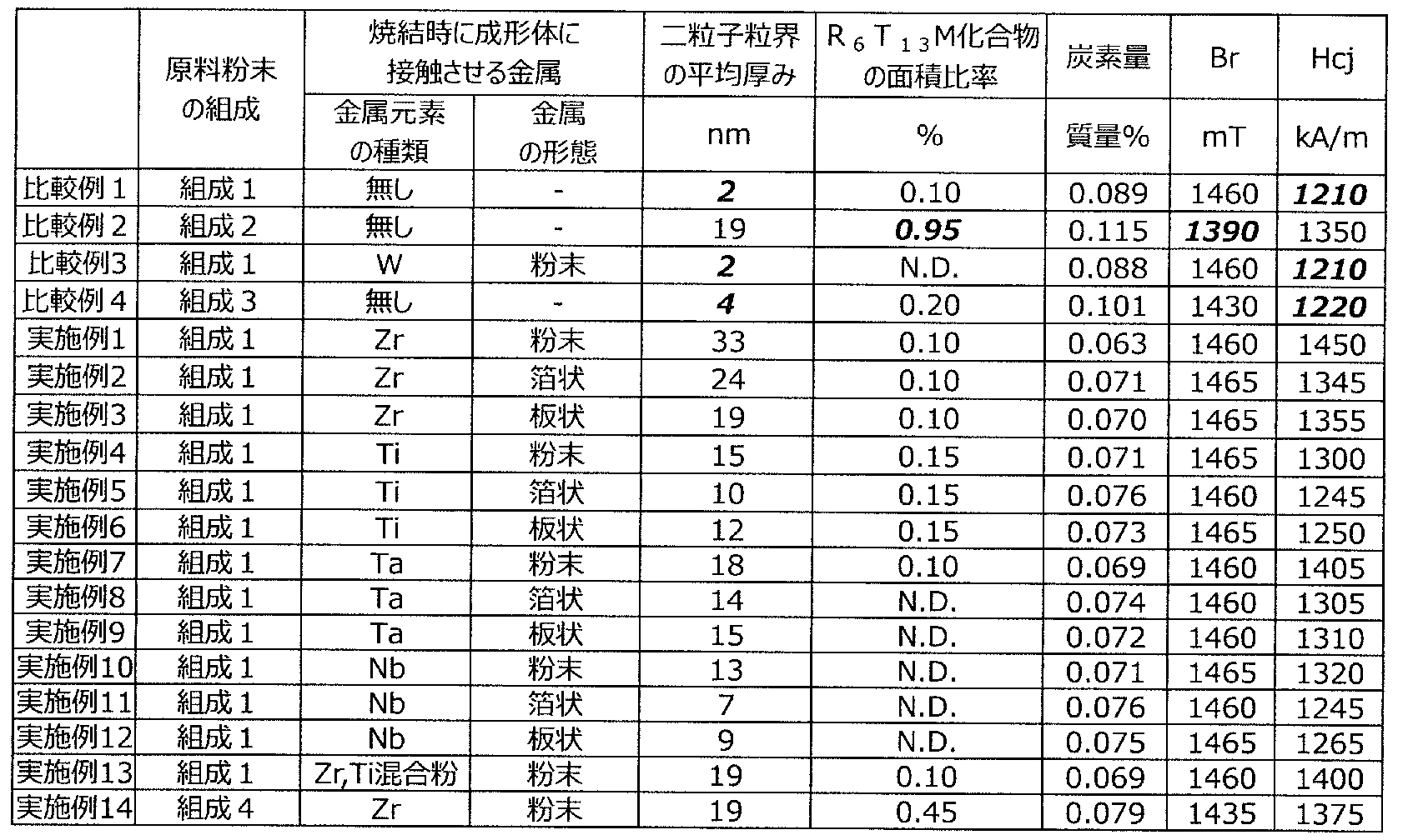
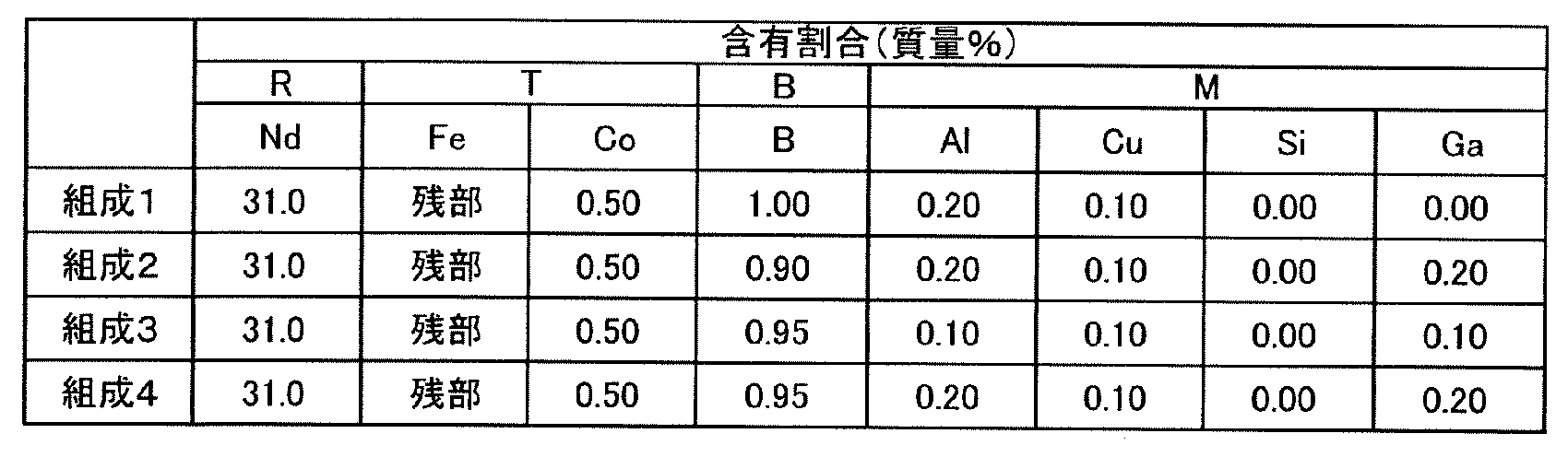
表1より、成形体に金属元素としてZr、Ti、Ta、Nbから選択される1種または2種を接触させて焼結した実施例1~14は、成形体に金属元素を接触させなかった比較例1、2、4、および、成形体に金属元素としてWを接触させた比較例3と比較して、炭素量が少なくなった。そして、二粒子粒界の平均厚みが5nm以上50nm以下であり、かつ、R6T13M化合物の面積比率が0.50%以下となった。そして、BrおよびHcjが良好であった。
比較例1~4のうち、Bの含有量が比較的多い1.00質量%でありGaを含有しない比較例である比較例1、3は炭素量が多くなった。そして、図3に示すように二粒子粒界の平均厚みが低くなった。その結果、実施例と比較してHcjが低下した。なお、比較例1、3からRの量を増加させたとしても、粒界三重点の面積比率が増加しやすく二粒子粒界の平均厚みを5nm以上とすることは困難である。
比較例1~4のうち、Bの含有量が比較的少ない0.90質量%でありGaの含有量が比較的多い0.20質量%である比較例2は炭素量が多くなった。そして、粒界三重点の面積比率が増大し、炭素を含む副相やR6T13M相の面積比率が増大した。その結果、実施例と比較してBrが低下した。
比較例1~4のうち、Bの含有量が0.95質量%でありGaの含有量が0.10質量%である比較例4は炭素量が多くなり、二粒子粒界の平均厚みが低くなった。その結果、実施例と比較してHcjが低下した。
なお、金属元素としてWを接触させた比較例3において、得られる永久磁石の炭素量が多くなったのは、WからW炭化物を生成するための標準生成ギブスエネルギーが、NdからNd炭化物を生成するための標準生成ギブスエネルギーよりも高いためである。これに対し、実施例1~14において得られる永久磁石の炭素量が少なくなったのは、Zr、Ti、Ta、Nbからこれらの炭化物を生成するための標準生成ギブスエネルギーが、NdからNd炭化物を生成するための標準生成ギブスエネルギーよりも低いためである。
(実験例2)
実験例2では、原料粉末の組成を表2の組成1とし、焼結時に成形体に接触させる金属元素の種類を変化させた点以外は、実験例1と同様に実施した。結果を表3に示す。
実験例2では、原料粉末の組成を表2の組成1とし、焼結時に成形体に接触させる金属元素の種類を変化させた点以外は、実験例1と同様に実施した。結果を表3に示す。

表3より、金属元素の種類をVまたはCrに変化させた実施例21~26は、比較例1~4と比較して炭素量が少なくなった。そして、二粒子粒界の平均厚みが5nm以上であり、かつ、R6T13M化合物の面積比率が0.50%以下となった。そして、BrおよびHcjが良好であった。
(実験例3)
実験例3では、原料粉末の組成を表4に示す組成とした点以外は、実験例1と同様に実施した。結果を表4に示す。
実験例3では、原料粉末の組成を表4に示す組成とした点以外は、実験例1と同様に実施した。結果を表4に示す。
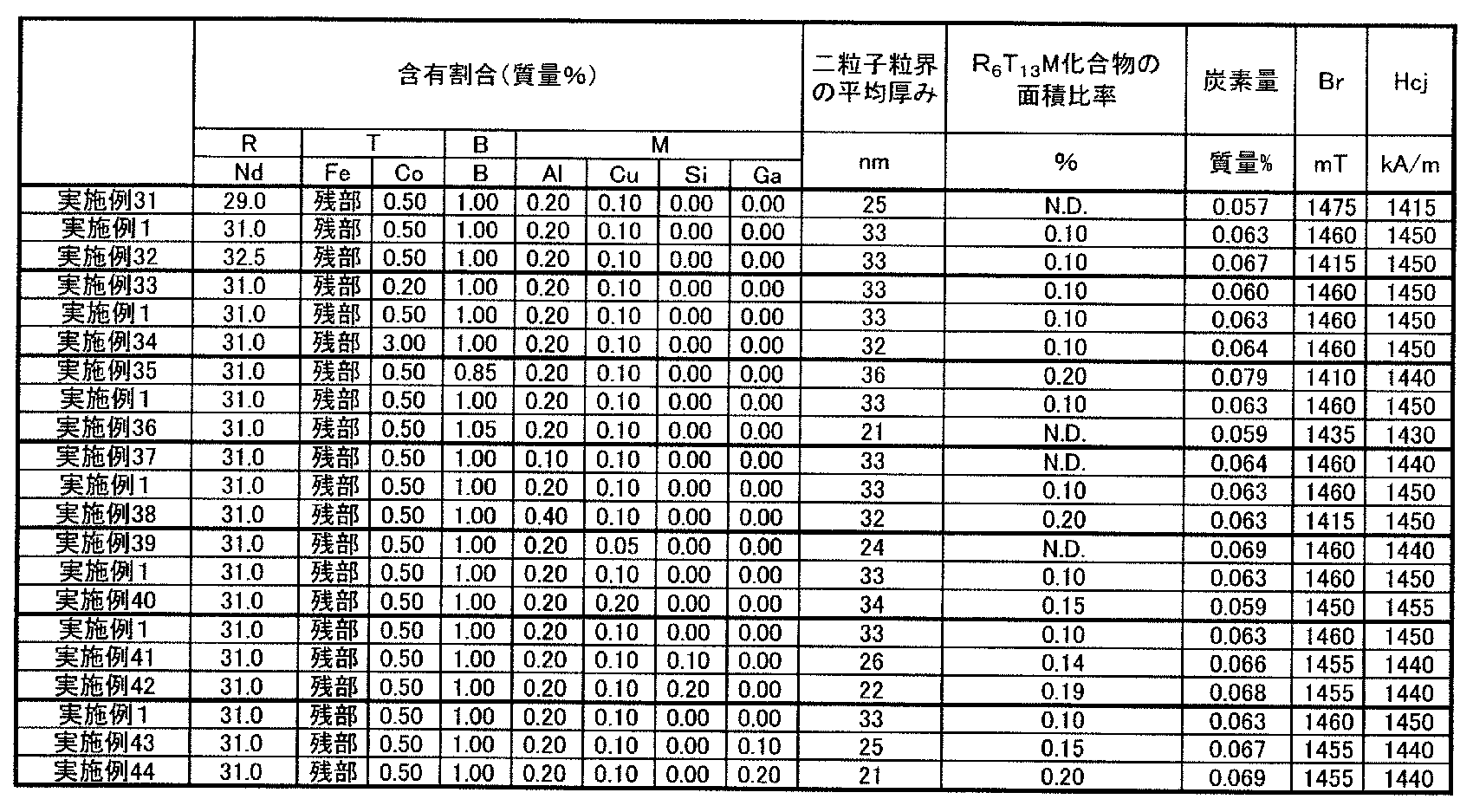
表4より、原料粉末の組成を変化させても、得られた実施例31~44は、比較例1~4と比較して炭素量が少なくなった。そして、二粒子粒界の平均厚みが5nm以上50nm以下であり、かつ、R6T13M化合物の面積比率が0.50%以下となった。そして、BrおよびHcjが良好であった。
なお、Bの含有量が比較的多い実施例36は、Bの含有量以外、同条件で実施した実施例1と比較してBrおよびHcjが低下した。Bの含有量が多い場合には、希土類元素のホウ化物などの副相が生じやすいためである。
(実験例4)
実験例4では、金属粉末の量を変化させた点以外は実施例1と同様に実施した。結果を表5に示す。
実験例4では、金属粉末の量を変化させた点以外は実施例1と同様に実施した。結果を表5に示す。
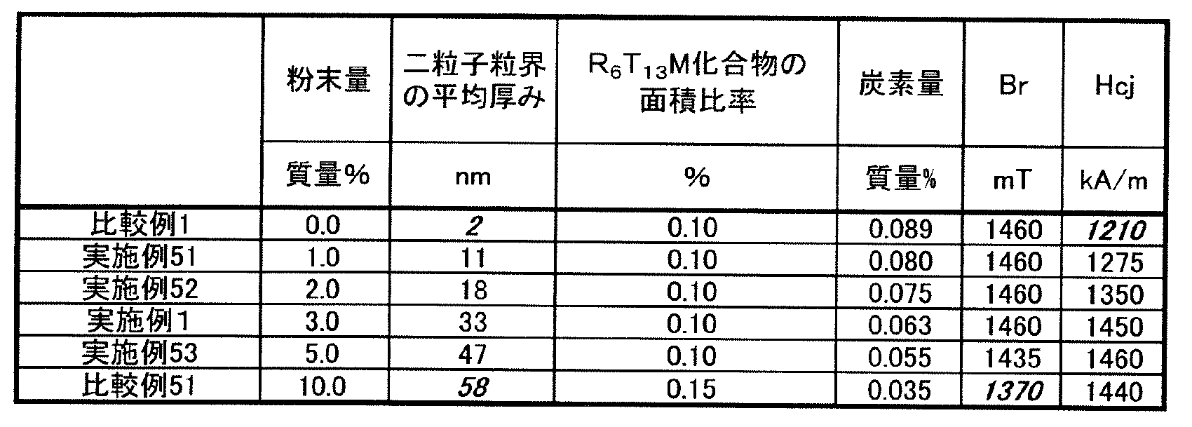
表5より、金属粉末の量が多いほど炭素量が低減し、二粒子粒界の平均厚みが厚くなった。そして、二粒子粒界の平均厚みが5nm以上50nm以下である各実施例は比較例1~4と比較して炭素量が少なくなった。そして、R6T13M化合物の面積比率が0.50%以下となった。そして、BrおよびHcjが良好であった。なお、比較例1、実施例1および実施例51~53では、金属粉末の量が少なくなるほどHcjが低下した。これは、金属粉末の量が少なくなるほど、希土類永久磁石中の炭素の含有割合を低減させる効果が小さくなり、二粒子粒界の平均厚みが薄くなる傾向があるためである。
これに対し、比較例51は二粒子粒界の平均厚みが厚くなりすぎた。その結果、Brが低下した。また、比較例51では、炭素量が少なくなったことに伴い、R6T13M化合物の面積比率が増加し、R2Fe17化合物が粒界に生成した。その結果、実施例1および実施例53と比較してHcjも低下した。
1 主相結晶粒子
2 二粒子粒界
3 粒界三重点
6a、6b 境界
2 二粒子粒界
3 粒界三重点
6a、6b 境界
Claims (6)
- RはNdまたはPrを必須とする1種以上の希土類元素、TはFeを必須とする1種以上の鉄族元素、Bはホウ素であり、Ga、Al、CuおよびSiのうち少なくとも1種以上であるMを含むR-T-B系永久磁石であって、
前記R-T-B系永久磁石が、R2T14B結晶からなる主相粒子と、隣接する二つの主相粒子の間に存在する二粒子粒界と、を含み、
前記二粒子粒界の平均厚みは5nm以上50nm以下であり、
任意の断面におけるR6T13M化合物の面積比率が0.50%以下(0%を含む)であるR-T-B系永久磁石。 - RはNdまたはPrを必須とする1種以上の希土類元素、TはFeを必須とする1種以上の鉄族元素、Bはホウ素であり、
R2T14B結晶からなる主相粒子と、隣接する二つの主相粒子の間に存在する二粒子粒界と、を含むR-T-B系永久磁石の製造方法であって、
成形体を形成する工程と、
金属が付着した成形体を焼結する工程と、を含み、
前記金属から金属炭化物を生成するための標準生成ギブスエネルギーが、Rとして前記成形体中に主に含まれる希土類元素から当該希土類元素の炭化物を生成するための標準生成ギブスエネルギーよりも低いR-T-B系永久磁石の製造方法 - 前記金属がZr、Ti、Ta、Nb、VおよびCrのうち少なくとも1種以上である請求項2に記載のR-T-B系永久磁石の製造方法。
- 前記金属が粉体である請求項2または3に記載のR-T-B系永久磁石の製造方法。
- 前記金属が板状である請求項2または3に記載のR-T-B系永久磁石の製造方法。
- 前記金属が箔状である請求項2または3に記載のR-T-B系永久磁石の製造方法。
Priority Applications (4)
| Application Number | Priority Date | Filing Date | Title |
|---|---|---|---|
| CN202080019921.6A CN113614864B (zh) | 2019-03-13 | 2020-03-10 | R-t-b系永久磁体及其制造方法 |
| US17/438,796 US20220148772A1 (en) | 2019-03-13 | 2020-03-10 | R-t-b based permanent magnet and method for manufacturing same |
| JP2021505084A JP7256483B2 (ja) | 2019-03-13 | 2020-03-10 | R-t-b系永久磁石およびその製造方法 |
| DE112020001199.2T DE112020001199T5 (de) | 2019-03-13 | 2020-03-10 | Dauermagnet auf R-T-B-Basis und Verfahren zur Herstellung desselben |
Applications Claiming Priority (2)
| Application Number | Priority Date | Filing Date | Title |
|---|---|---|---|
| JP2019046401 | 2019-03-13 | ||
| JP2019-046401 | 2019-03-13 |
Publications (1)
| Publication Number | Publication Date |
|---|---|
| WO2020184565A1 true WO2020184565A1 (ja) | 2020-09-17 |
Family
ID=72426076
Family Applications (1)
| Application Number | Title | Priority Date | Filing Date |
|---|---|---|---|
| PCT/JP2020/010320 Ceased WO2020184565A1 (ja) | 2019-03-13 | 2020-03-10 | R-t-b系永久磁石およびその製造方法 |
Country Status (5)
| Country | Link |
|---|---|
| US (1) | US20220148772A1 (ja) |
| JP (1) | JP7256483B2 (ja) |
| CN (1) | CN113614864B (ja) |
| DE (1) | DE112020001199T5 (ja) |
| WO (1) | WO2020184565A1 (ja) |
Families Citing this family (3)
| Publication number | Priority date | Publication date | Assignee | Title |
|---|---|---|---|---|
| CN110993233B (zh) * | 2019-12-09 | 2021-08-27 | 厦门钨业股份有限公司 | 一种r-t-b系永磁材料、原料组合物、制备方法、应用 |
| CN118231076A (zh) * | 2022-12-13 | 2024-06-21 | 南通正海磁材有限公司 | 一种特微尺寸高性能的烧结钕铁硼磁体及其制备方法 |
| CN119763967B (zh) * | 2024-12-30 | 2026-02-06 | 宁波科宁达工业有限公司 | 一种高剩磁高矫顽力磁体及其制备方法 |
Citations (3)
| Publication number | Priority date | Publication date | Assignee | Title |
|---|---|---|---|---|
| JP2005276949A (ja) * | 2004-03-23 | 2005-10-06 | Neomax Co Ltd | 希土類焼結磁石の製造方法 |
| JP2006265600A (ja) * | 2005-03-23 | 2006-10-05 | Tdk Corp | 希土類磁石焼結用敷板及びそれを用いた希土類磁石の製造方法 |
| WO2007077809A1 (ja) * | 2005-12-28 | 2007-07-12 | Hitachi Metals, Ltd. | 希土類磁石およびその製造方法 |
Family Cites Families (14)
| Publication number | Priority date | Publication date | Assignee | Title |
|---|---|---|---|---|
| EP2518742B1 (en) * | 2003-06-27 | 2016-11-30 | TDK Corporation | R-T-B system permanent magnet |
| JP2009231391A (ja) * | 2008-03-19 | 2009-10-08 | Hitachi Metals Ltd | R−t−b系焼結磁石 |
| JP5572673B2 (ja) * | 2011-07-08 | 2014-08-13 | 昭和電工株式会社 | R−t−b系希土類焼結磁石用合金、r−t−b系希土類焼結磁石用合金の製造方法、r−t−b系希土類焼結磁石用合金材料、r−t−b系希土類焼結磁石、r−t−b系希土類焼結磁石の製造方法およびモーター |
| DE112013003109T5 (de) | 2012-06-22 | 2015-02-26 | Tdk Corp. | Gesinterter Magnet |
| JP6303480B2 (ja) * | 2013-03-28 | 2018-04-04 | Tdk株式会社 | 希土類磁石 |
| JP6319299B2 (ja) | 2013-03-29 | 2018-05-09 | 日立金属株式会社 | R−t−b系焼結磁石 |
| WO2014157451A1 (ja) * | 2013-03-29 | 2014-10-02 | 日立金属株式会社 | R-t-b系焼結磁石 |
| JP6414059B2 (ja) | 2013-07-03 | 2018-10-31 | Tdk株式会社 | R−t−b系焼結磁石 |
| JP6142793B2 (ja) * | 2013-12-20 | 2017-06-07 | Tdk株式会社 | 希土類磁石 |
| CN104388951B (zh) * | 2014-11-24 | 2017-06-06 | 上海交通大学 | 一种提高烧结钕铁硼磁性能的晶界扩散方法 |
| US10529473B2 (en) * | 2016-03-28 | 2020-01-07 | Tdk Corporation | R-T-B based permanent magnet |
| CN105755441B (zh) * | 2016-04-20 | 2019-01-11 | 中国科学院宁波材料技术与工程研究所 | 一种磁控溅射法扩渗重稀土提高烧结钕铁硼矫顽力的方法 |
| JP6848735B2 (ja) * | 2016-07-15 | 2021-03-24 | Tdk株式会社 | R−t−b系希土類永久磁石 |
| JP7315888B2 (ja) | 2018-05-29 | 2023-07-27 | Tdk株式会社 | R-t-b系永久磁石およびその製造方法 |
-
2020
- 2020-03-10 WO PCT/JP2020/010320 patent/WO2020184565A1/ja not_active Ceased
- 2020-03-10 JP JP2021505084A patent/JP7256483B2/ja active Active
- 2020-03-10 US US17/438,796 patent/US20220148772A1/en active Pending
- 2020-03-10 DE DE112020001199.2T patent/DE112020001199T5/de active Pending
- 2020-03-10 CN CN202080019921.6A patent/CN113614864B/zh active Active
Patent Citations (3)
| Publication number | Priority date | Publication date | Assignee | Title |
|---|---|---|---|---|
| JP2005276949A (ja) * | 2004-03-23 | 2005-10-06 | Neomax Co Ltd | 希土類焼結磁石の製造方法 |
| JP2006265600A (ja) * | 2005-03-23 | 2006-10-05 | Tdk Corp | 希土類磁石焼結用敷板及びそれを用いた希土類磁石の製造方法 |
| WO2007077809A1 (ja) * | 2005-12-28 | 2007-07-12 | Hitachi Metals, Ltd. | 希土類磁石およびその製造方法 |
Also Published As
| Publication number | Publication date |
|---|---|
| CN113614864A (zh) | 2021-11-05 |
| US20220148772A1 (en) | 2022-05-12 |
| CN113614864B (zh) | 2023-08-04 |
| DE112020001199T5 (de) | 2021-11-25 |
| JPWO2020184565A1 (ja) | 2020-09-17 |
| JP7256483B2 (ja) | 2023-04-12 |
Similar Documents
| Publication | Publication Date | Title |
|---|---|---|
| US10096412B2 (en) | Rare earth based magnet | |
| CN105960690B (zh) | R-t-b系烧结磁体及其制造方法 | |
| JP5561170B2 (ja) | R−t−b系焼結磁石の製造方法 | |
| US10748686B2 (en) | R-T-B based sintered magnet | |
| JP4605013B2 (ja) | R−t−b系焼結磁石および希土類合金 | |
| JP7247670B2 (ja) | R-t-b系永久磁石およびその製造方法 | |
| JP6094612B2 (ja) | R−t−b系焼結磁石の製造方法 | |
| JP2016152246A (ja) | 希土類系永久磁石 | |
| JP6468435B2 (ja) | R−t−b系焼結磁石 | |
| US20020017338A1 (en) | Rare earth magnet and method for making same | |
| US10734143B2 (en) | R-T-B based sintered magnet | |
| JP2002327255A (ja) | 焼結磁石 | |
| JP7256483B2 (ja) | R-t-b系永久磁石およびその製造方法 | |
| JP2024023206A (ja) | 異方性希土類焼結磁石及びその製造方法 | |
| JP2018174314A (ja) | R−t−b系焼結磁石 | |
| JP2018174312A (ja) | R−t−b系焼結磁石 | |
| JP5910074B2 (ja) | R−T−Zr−B系希土類金属磁石 | |
| US10748685B2 (en) | R-T-B based sintered magnet | |
| JP6511844B2 (ja) | R−t−b系焼結磁石 | |
| WO2021193333A1 (ja) | 異方性希土類焼結磁石及びその製造方法 | |
| JP2006041507A (ja) | 焼結磁石 | |
| JP7698586B2 (ja) | R-t-b系永久磁石 | |
| JP2024146728A (ja) | R-t-b系永久磁石 | |
| JP2014216340A (ja) | R−t−b系焼結磁石 |
Legal Events
| Date | Code | Title | Description |
|---|---|---|---|
| 121 | Ep: the epo has been informed by wipo that ep was designated in this application |
Ref document number: 20771086 Country of ref document: EP Kind code of ref document: A1 |
|
| ENP | Entry into the national phase |
Ref document number: 2021505084 Country of ref document: JP Kind code of ref document: A |
|
| 122 | Ep: pct application non-entry in european phase |
Ref document number: 20771086 Country of ref document: EP Kind code of ref document: A1 |