WO2020184465A1 - 歯車用材料保持装置および歯車用材料取り付け方法 - Google Patents
歯車用材料保持装置および歯車用材料取り付け方法 Download PDFInfo
- Publication number
- WO2020184465A1 WO2020184465A1 PCT/JP2020/009793 JP2020009793W WO2020184465A1 WO 2020184465 A1 WO2020184465 A1 WO 2020184465A1 JP 2020009793 W JP2020009793 W JP 2020009793W WO 2020184465 A1 WO2020184465 A1 WO 2020184465A1
- Authority
- WO
- WIPO (PCT)
- Prior art keywords
- holding member
- pull rod
- machine tool
- gear
- hollow cylindrical
- Prior art date
- Legal status (The legal status is an assumption and is not a legal conclusion. Google has not performed a legal analysis and makes no representation as to the accuracy of the status listed.)
- Ceased
Links
Images


Classifications
-
- B—PERFORMING OPERATIONS; TRANSPORTING
- B23—MACHINE TOOLS; METAL-WORKING NOT OTHERWISE PROVIDED FOR
- B23B—TURNING; BORING
- B23B31/00—Chucks; Expansion mandrels; Adaptations thereof for remote control
- B23B31/02—Chucks
- B23B31/10—Chucks characterised by the retaining or gripping devices or their immediate operating means
- B23B31/12—Chucks with simultaneously-acting jaws, whether or not also individually adjustable
- B23B31/20—Longitudinally-split sleeves, e.g. collet chucks
- B23B31/201—Characterized by features relating primarily to remote control of the gripping means
- B23B31/207—Characterized by features relating primarily to remote control of the gripping means using mechanical transmission through the spindle
- B23B31/2073—Axially fixed cam, moving jaws
-
- B—PERFORMING OPERATIONS; TRANSPORTING
- B23—MACHINE TOOLS; METAL-WORKING NOT OTHERWISE PROVIDED FOR
- B23F—MAKING GEARS OR TOOTHED RACKS
- B23F23/00—Accessories or equipment combined with or arranged in, or specially designed to form part of, gear-cutting machines
- B23F23/02—Loading, unloading or chucking arrangements for workpieces
- B23F23/06—Chucking arrangements
Definitions
- the present invention relates to a holding device for attaching a material of a gear to a machine tool when manufacturing the gear.
- gear cutting in addition to cutting the outer surface of a disk-shaped rough member to finish it into a precise shape and forming a conical outer shape for bevel gears. ..
- gear cutting in addition to cutting the outer surface of a disk-shaped rough member to finish it into a precise shape and forming a conical outer shape for bevel gears. ..
- a material for gears is attached to a rotating part of a machine tool such as a lathe, and necessary processing is performed while rotating the gears.
- Patent Document 1 In order to attach the gear material to the machine tool, a chuck that grips the gear material from the outside by a plurality of claws as in Patent Document 1 is usually used. Further, Patent Document 2 and Patent Document 3 describe that the gear material is attached to the machine tool by sandwiching it between members in contact with the upper surface and the lower surface of the gear material.
- the present invention provides a material holding device for gears and a material mounting method for gears, which can be mounted by accurately aligning the rotation axis of a machine tool with the center position of a hole in the center of the material for gears and which can be easily attached and detached.
- the purpose is.
- the gear material holding device of the present invention is a device for rotatably holding a gear material having a circular hole in the center in a machine tool, and is a device for rotatably holding a circular hole of the gear material. It has a holding member having a hollow cylindrical portion in contact with the side wall of the holding member, and a pull rod inserted into the hollow cylindrical portion of the holding member, and the end portion of the hollow cylindrical portion of the holding member is along the length direction. A divided portion divided by a plurality of cuts is formed, At the end of the pull rod, a tapered portion is formed so that the outer diameter increases toward the tip, and the holding member is detachably attached to the machine tool, and the pull rod is held.
- the split part of the holding member expands and the circular hole of the material for gears. It is designed to be pressed against the side wall of the.
- it is a device for holding a material for gears having a circular hole in the central portion, and has a machine tool connecting member connected to the machine tool and a hollow cylindrical portion in contact with the side wall of the circular hole of the material for gears. It has a member and a pull rod to be inserted into the hollow cylindrical portion of the holding member, and a divided portion divided by a plurality of notches along the length direction is formed at the end of the hollow cylindrical portion of the holding member.
- a tapered portion is formed so that the outer diameter increases toward the tip, and the holding member can be detachably attached to the machine tool connecting member.
- the pull rod can move back and forth along the length direction with respect to the holding member, and when the tapered portion of the pull rod enters the split portion of the holding member, the split portion of the holding member expands. It is designed to be pressed against the side wall of the circular hole of the gear material.
- the above-mentioned material holding device for a gear is installed in a machine tool, a circular hole of the material for the gear is fitted into a hollow cylindrical portion of the material for the gear, and a pull rod is attached to the holding member.
- the gear material is attached to the machine tool by moving it in the length direction to allow the tapered portion of the pull rod to enter the split portion of the holding member, expanding the split portion and pressing it against the side wall of the circular hole of the gear material. ..
- the material for gears can be easily attached to and detached from the machine tool, and the rotation axis of the machine tool is accurately positioned at the center of the hole in the center of the material for gears. It can be installed together to achieve precise processing.
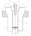
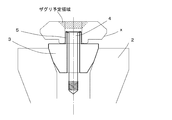
- FIG. 1 is a cross-sectional view showing a material holding device for gears.
- the gear material holding device 1 is a device for holding the gear material x having a circular hole x1 in the central portion. It has a machine tool connecting member 2 connected to the machine tool y, a holding member 3, and a pull rod 4.
- the material holding device 1 for vehicles can be applied to various shapes of materials for gears. For example, in addition to cylindrical materials for spur gears, materials having a truncated cone shape such as materials for bevel gears can be used. Can also be applied. In this example, a gear material for a spiral bevel gear is shown. In such a shape, the side surface portion having the maximum diameter is small, it is difficult to grip it from the outside with a conventional chuck, and when it is sandwiched from above and below, the upper truncated cone-shaped portion cannot be processed.
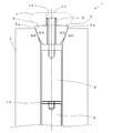
- FIG. 2 is a cross-sectional view showing a machine tool connecting member
- FIG. 3 is a plan view of the same.
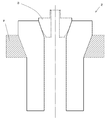
- the machine tool used in the present invention may be various general machine tools used for manufacturing gears and pretreatment. These machine tools have a member y that is driven by a drive source (not shown) such as a motor to rotate, and is provided with a portion for attaching a member that holds a material for gears such as a chuck. In this example, a truncated cone-shaped recess that opens upward is formed, and the machine tool connecting member 2 is fixed there. If the machine tool itself does not have such a rotating part of an appropriate shape, it may be appropriately created and replaced with the rotating part of the original machine tool.
- the outer shape of the machine tool connecting member 2 is formed in a shape that can be attached to the rotating portion of the machine tool.
- the outer side surface has a tapered portion, which contacts the surface of the truncated cone-shaped recess of the machine tool.
- a hollow portion is formed in the central portion of the machine tool connecting member 2 along the central axis. Especially near the upper end, the hollow portion is a conical depression that opens upward. Then, it is preferable that the tapered surface on the outer side surface and the conical concave surface in the central portion are polished over the entire surface.
- the polishing finish improves the connection between the machine tool and the holding member described below and reduces backlash when the machine tool is rotated for machining. In this way, more precise machining can be realized.
- FIG. 4 is a cross-sectional view showing a holding member
- FIG. 5 is a front view thereof
- FIG. 6 is a plan view.
- the holding member 3 also has a hollow central portion.
- the base portion has a substantially truncated cone shape in outer shape, and has a tapered surface that engages with the recessed portion of the machine tool connecting member 2.
- a stronger taper angle is formed on the outer circumference of the lower end portion to facilitate insertion.
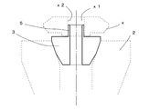
- a hollow cylindrical portion 5 is formed on the upper portion of the holding member 3. Its outer shape corresponds to the shape of the circular hole in the gear material to be retained, but slightly smaller. Then, at least the tip portion of the hollow cylindrical portion 5 is formed with a divided portion divided by a plurality of notches 6 along the length direction.
- the number of cuts that is, the number of divisions is preferably 3 or more and 6 or less, and particularly preferably divided into four equal parts by four cuts 6 as shown in FIG. Further, the depth of the notch 6 is set within the circular hole of the gear material by bending so that an appropriate deflection occurs when the tip portion of the pull rod 4 is lowered, that is, the split portion opens outward.
- the notch 6 may be provided only near the upper end portion of the hollow cylindrical portion 5, but in this example, the notch 6 is provided over the entire length of the hollow cylindrical portion 5.
- a tapered surface is formed so that the wall thickness becomes thinner toward the upper side.
- FIG. 7 is a front view showing a pull rod
- FIG. 8 is a plan view of the same.
- the lower part of the pull rod 4 is a round bar-shaped member, and the outer diameter of the portion is smaller than the diameter of the hollow hole of the holding member 3, and even if it is inserted into the hollow hole of the holding member 3, the holding member There is a gap between it and the inner wall of 3.
- the upper portion of the pull rod 4 is formed with a tapered portion such that the outer diameter increases toward the tip.
- This taper angle is substantially the same as the taper angle of the inner wall surface of the upper end portion of the hollow cylindrical portion 5.
- the presence of this tapered portion expands the divided portion of the hollow cylindrical portion 5 when the pull rod 4 is lowered.
- a large taper angle is provided so that the divided portion can be greatly widened with a small amount of movement, and is set to, for example, 75 ° with respect to the axial direction.
- the diameter of the upper end surface is larger than the inner diameter of the hollow cylindrical portion 5.
- a male screw portion is formed at the lower end portion of the pull rod 4. Further, a tool insertion hole 7 into which the tip of a fastening tool such as a screwdriver or a hexagon wrench is inserted is formed on the upper surface. In this example, a cross hole for a Phillips screwdriver is provided.
- a rod-shaped connecting member 8 is provided below the pull rod 4.
- a female screw portion is provided at the center of the upper end portion of the connecting member 8.
- an engaging portion such as a male screw portion is also formed at the lower end portion of the connecting member 8 so that the connecting member 8 can be connected to the driving member 9.
- the drive member 9 is a member that moves the pull rod 4 and the connecting member 8 back and forth along the axial direction by a drive source such as a hydraulic device, and further, the pull rod 4 and the connecting member with respect to the main body of the machine tool. 8 is rotatably supported.
- a drive member 9 is often installed in many machine tools, in which case it may be used. If a suitable drive member is not provided, it may be created and attached separately.
- the connecting member 8 may be set to be slightly shorter so that a gap is formed between the connecting member 8 and the driving member 9, and the washer-shaped spacer 10 may be used for adjustment at the time of connection.
- the machine tool connecting member, the holding member, and the pull rod which are the main members of the material holding device 1 for gears, are made of a strong material.
- metal materials steel materials having high strength and good availability are preferable.
- chrome molybdenum steel is suitable for the holding member 3 and the pull rod 4.
- JIS G4053 alloy steel for machine structure classified by SCM415 is used. This is a material suitable for quenching, and in this example, carburizing and quenching is performed.
- FIG. 10 shows a portion where quenching is performed. It is particularly preferable to quench the tapered portion Q1 of the pull rod 4 and the tapered surface Q2 of the hollow cylindrical portion 5. Since these parts are pressed against each other with a strong force, wear is likely to proceed. By quenching, wear can be suppressed and a long life can be realized, and by maintaining the accuracy of the shape, the material for gears can be accurately held. Further, in the divided portion 5, all the portions other than the tapered surface Q2 at the tip may be hardened. In this case, it is preferable to first prepare a cylindrical member, then perform quenching, and then make a cut along the length direction.
- the fitting tolerance between the holding member 3 and the machine tool connecting member 2 is preferably JIS H8 or more. As a result, accurate rotation with small runout can be provided to the gear material during machining, and a highly accurate gear can be obtained. Further, it is preferable to form a portion 3a having a cylindrical side surface shape on the tapered portion Q5 at the base of the holding member 3. This portion 3a can be gripped when the machine tool connecting member 2 is attached to or detached from the rotating portion of the machine tool as described later.
- the material holding device 1 for gears is assembled.
- the material holding device 1 for gears is divided into a machine tool connecting member 2, a holding member 3, and a pull rod 4, and in this example, a connecting member 8 is also included.
- a holding member 3 a plurality of types are prepared according to the shape of the gear material x that can be used, particularly the inner diameter and depth of the circular hole x 1, and the gear material at that time is prepared.
- the holding member suitable for x can be selected.
- a plurality of types of the pull rod 4 and the connecting member 8 can be similarly prepared. In this way, by combining the members of the respective parts, it is possible to manufacture various kinds of gears by exchanging only a part of the material holding device 1 for gears without exchanging all of them.
- FIG. 9 is an enlarged cross-sectional view showing a hollow cylindrical portion of the holding member.
- the pull rod 4 is set to the upper position.
- the upper end portion of the pull rod 4 is separated from the upper end portion of the hollow cylindrical portion 5 or is in a weak contact state.
- the divided portion of the hollow cylindrical portion 5 is not expanded, and the circular hole x1 of the gear material x can be fitted into the hollow cylindrical portion 5.
- the drive member 9 is operated to pull the pull rod 4 downward.
- the upper end portion of the pull rod 4 is lowered, whereby an outward force is applied to the upper end portion of the divided portion of the hollow cylindrical portion 5.
- the upper end of the split portion is expanded while flexing outward, and is pressed against the inner side surface x2 of the circular hole x1 of the gear material x.
- the gear material x is firmly fixed to the holding member 3.
- the center position of the circular hole x1 accurately matches the position of the central axis of the holding member 3.
- the upper end portion of the pull rod 4 also applies a downward force to the upper end portion of the pull rod 4.
- the material holding device 1 for gears is firmly fixed to the rotating portion y of the machine tool.
- the gear material x can be attached only by fitting the circular hole x1 of the gear material x into the hollow cylindrical portion 5 and pulling down the pull rod 4 with the drive member 9.
- the rotating portion y of the machine tool can be rotated to perform necessary machining processes such as pre-machining and gear cutting.
- the outer circumference of the gear material x is completely open, and there is nothing that interferes with the processing work. Even if it has a complicated shape such as the gear material for the spiral bevel gear of this example, it can be fixed easily and surely, and all the outer surfaces can be freely processed.
- the inner diameter of the circular hole x1 corresponds to the outer shape of the hollow cylindrical portion 5, any material for gears having an outer shape can be held.
- the outer shape of the gear material x is rough, and it is possible that the center position of the outer circumference and the center position of the circular hole do not match.
- the center of rotation of the rotating portion y of the machine tool coincides with the center position of the circular hole x1. Therefore, in the final gear, the tooth surface rotates accurately about the central axis.
- the rotation of the rotating portion y of the machine tool is stopped.
- the drive member 9 is operated to move the pull rod 4 upward, and the state is returned to the state shown in FIG. 9A.
- the upper end of the split portion shrinks and separates from the inner surface x2 of the circular hole x1 of the gear material x. In this way, the gear material x after the processing can be easily removed.
- the holding member can be attached to and detached from the machine tool connecting member by the vertical movement of the pull rod 4 due to the operation of the driving member 9. There is no need to use tools such as a screwdriver or spanner.
- the operation of the drive member 9 can also be automatically controlled. Therefore, by automatically controlling the vertical movement of the drive member 9, the attachment and detachment of the gear material x can be automated, the work can be automated and speeded up, and the safety can be improved.
- FIG. 11 is a cross-sectional view showing an example of a material mounting method for gears.
- the inside of the center hole may also be processed.
- the central portion may be counterbored in a shape that is open outward. In this case, counterbore processing is performed while the cutting blade is inserted into the central portion.
- the portion to be counterbore is shown by hatching.
- the shape of the tip of the pull rod and the tip of the empty cylindrical portion of the holding member is set so as to be located deeper than the counterbore depth. In this position, hold the gear material. As a result, the pull rod and the holding member do not interfere with the cutting blade, so that counterbore processing can be performed safely and easily.
- FIG. 12 is a cross-sectional view showing a second example of the material holding device for gears.
- the holding member 3 is directly attached to the rotating portion y of the machine tool.
- Some machine tools do not have a rotating portion y suitable for connecting the machine tool connecting member 2 as shown in FIG. In such a case, it is conceivable to create a rotating portion y as shown in FIG. 1 to replace the original rotating portion, but in this example, as shown in FIG. 12, a hollow portion for attaching the holding member 3 is attached. However, it is formed along the central axis in the central portion, and the hollow portion is a conical depression that opens upward in the vicinity of the upper end portion thereof.
- the holding member 3 By mounting the holding member 3 in the conical recess, the holding member 3 can be rotatably attached to the machine tool.
- the tapered portion of the holding member 3 may be provided in a large range on the upper side. In this case, a part of the tapered portion of the holding member 3 protrudes above the conical recess of the hollow portion of the rotating portion y of the machine tool. It becomes a state.
Landscapes
- Engineering & Computer Science (AREA)
- Mechanical Engineering (AREA)
- Gear Processing (AREA)
- Gripping On Spindles (AREA)
- Gears, Cams (AREA)
Priority Applications (2)
| Application Number | Priority Date | Filing Date | Title |
|---|---|---|---|
| JP2021505041A JP7382657B2 (ja) | 2019-03-14 | 2020-03-06 | 歯車用材料保持装置および歯車用材料取り付け方法 |
| JP2023185236A JP2023184611A (ja) | 2019-03-14 | 2023-10-30 | 歯車用材料保持装置および歯車用材料取り付け方法 |
Applications Claiming Priority (2)
| Application Number | Priority Date | Filing Date | Title |
|---|---|---|---|
| JP2019047377A JP6853926B2 (ja) | 2019-03-14 | 2019-03-14 | 歯車用材料保持装置および歯車用材料取り付け方法 |
| JP2019-047377 | 2019-03-14 |
Publications (1)
| Publication Number | Publication Date |
|---|---|
| WO2020184465A1 true WO2020184465A1 (ja) | 2020-09-17 |
Family
ID=72427488
Family Applications (1)
| Application Number | Title | Priority Date | Filing Date |
|---|---|---|---|
| PCT/JP2020/009793 Ceased WO2020184465A1 (ja) | 2019-03-14 | 2020-03-06 | 歯車用材料保持装置および歯車用材料取り付け方法 |
Country Status (2)
| Country | Link |
|---|---|
| JP (3) | JP6853926B2 (enExample) |
| WO (1) | WO2020184465A1 (enExample) |
Cited By (1)
| Publication number | Priority date | Publication date | Assignee | Title |
|---|---|---|---|---|
| CN116690463A (zh) * | 2023-07-24 | 2023-09-05 | 安徽星瑞齿轮传动有限公司 | 用于主减速齿轮固定的钢珠式多功能工装 |
Families Citing this family (3)
| Publication number | Priority date | Publication date | Assignee | Title |
|---|---|---|---|---|
| CN113416824B (zh) * | 2021-06-02 | 2022-09-13 | 重庆南雁实业集团龙剑机械制造有限公司 | 一种变速箱齿轮轴淬火工装 |
| CN114102275B (zh) * | 2021-11-19 | 2023-03-21 | 南京航空航天大学 | 一种适用于齿轮超声振动辅助磨削的装置及其运行工艺 |
| CN116000386B (zh) * | 2022-10-27 | 2024-07-02 | 湘潭大学 | 一种可变直径齿轮预应力施加装置 |
Citations (5)
| Publication number | Priority date | Publication date | Assignee | Title |
|---|---|---|---|---|
| JPS54120493A (en) * | 1978-03-10 | 1979-09-19 | Tsunashima Kikai Seisakushiyo | Work mounting device |
| JPS59183707U (ja) * | 1983-05-23 | 1984-12-07 | 株式会社 大隈鉄工所 | コレツト治具 |
| JPH1110420A (ja) * | 1997-06-23 | 1999-01-19 | Ntn Corp | 静圧空気軸受スピンドル |
| JP2002361534A (ja) * | 2001-06-11 | 2002-12-18 | Nissan Diesel Motor Co Ltd | フライス加工用のクランプ装置 |
| JP2014073574A (ja) * | 2013-12-04 | 2014-04-24 | Fuji Mach Mfg Co Ltd | ハイブリッドチャック |
-
2019
- 2019-03-14 JP JP2019047377A patent/JP6853926B2/ja active Active
-
2020
- 2020-03-06 JP JP2021505041A patent/JP7382657B2/ja active Active
- 2020-03-06 WO PCT/JP2020/009793 patent/WO2020184465A1/ja not_active Ceased
-
2023
- 2023-10-30 JP JP2023185236A patent/JP2023184611A/ja active Pending
Patent Citations (5)
| Publication number | Priority date | Publication date | Assignee | Title |
|---|---|---|---|---|
| JPS54120493A (en) * | 1978-03-10 | 1979-09-19 | Tsunashima Kikai Seisakushiyo | Work mounting device |
| JPS59183707U (ja) * | 1983-05-23 | 1984-12-07 | 株式会社 大隈鉄工所 | コレツト治具 |
| JPH1110420A (ja) * | 1997-06-23 | 1999-01-19 | Ntn Corp | 静圧空気軸受スピンドル |
| JP2002361534A (ja) * | 2001-06-11 | 2002-12-18 | Nissan Diesel Motor Co Ltd | フライス加工用のクランプ装置 |
| JP2014073574A (ja) * | 2013-12-04 | 2014-04-24 | Fuji Mach Mfg Co Ltd | ハイブリッドチャック |
Cited By (1)
| Publication number | Priority date | Publication date | Assignee | Title |
|---|---|---|---|---|
| CN116690463A (zh) * | 2023-07-24 | 2023-09-05 | 安徽星瑞齿轮传动有限公司 | 用于主减速齿轮固定的钢珠式多功能工装 |
Also Published As
| Publication number | Publication date |
|---|---|
| JP7382657B2 (ja) | 2023-11-17 |
| JP6853926B2 (ja) | 2021-04-07 |
| JP2023184611A (ja) | 2023-12-28 |
| JP2020146809A (ja) | 2020-09-17 |
| JPWO2020184465A1 (enExample) | 2020-09-17 |
Similar Documents
| Publication | Publication Date | Title |
|---|---|---|
| JP7382657B2 (ja) | 歯車用材料保持装置および歯車用材料取り付け方法 | |
| US7736101B2 (en) | Guided rotary file | |
| CN110814647B (zh) | 一种控制阀芯及其加工方法 | |
| CN103433703A (zh) | 一种长空心轴机加工艺 | |
| WO2011092969A1 (ja) | ドライバービット | |
| JP2000198025A (ja) | 精密機械工程および精密機械 | |
| JP5609291B2 (ja) | 内歯ギア製造用マンドレルおよびそのマンドレルを使用した内歯ギア製造方法と製造装置 | |
| KR101515358B1 (ko) | 롱비트 소켓 제조용 스웨이징 장치 및 롱비트 소켓 제조방법 | |
| CN111299967B (zh) | 一种金属螺旋筋的加工方法 | |
| JP2006076301A (ja) | 位置決め機構、及び位置決め治具 | |
| JP5689303B2 (ja) | 旋盤用チャック | |
| CN116252160A (zh) | 一种套筒类产品加工工装及加工方法 | |
| JP2007130673A (ja) | 軸受鋼管を用いたベアリングレースの外輪および内輪の製造方法 | |
| JP5375987B2 (ja) | シート面加工方法 | |
| JP5303336B2 (ja) | 傾斜歯筋歯車の鍛造装置 | |
| CN115194418A (zh) | 一种一体式异形薄壁壳体的加工工艺 | |
| JP3735362B1 (ja) | 位置決め治具 | |
| JP5755363B1 (ja) | 小径工具保持用チャック | |
| CN112453432A (zh) | 车用齿圈坯料套切方法 | |
| CN216859027U (zh) | 一种数控车削中心夹具 | |
| JPH11277314A (ja) | 切削工具 | |
| JPH088042Y2 (ja) | 工作機械の主軸における工具取付部の構造 | |
| CN213614157U (zh) | 一种内花键传动轴加工专用治具 | |
| JP2015009298A (ja) | 引きねじ加工機具と加工方法 | |
| CN214769406U (zh) | 一种可调倒角深度的孔口倒角工具 |
Legal Events
| Date | Code | Title | Description |
|---|---|---|---|
| 121 | Ep: the epo has been informed by wipo that ep was designated in this application |
Ref document number: 20770221 Country of ref document: EP Kind code of ref document: A1 |
|
| ENP | Entry into the national phase |
Ref document number: 2021505041 Country of ref document: JP Kind code of ref document: A |
|
| NENP | Non-entry into the national phase |
Ref country code: DE |
|
| 122 | Ep: pct application non-entry in european phase |
Ref document number: 20770221 Country of ref document: EP Kind code of ref document: A1 |