WO2020184351A1 - 非水二次電池用セパレータ及び非水二次電池 - Google Patents
非水二次電池用セパレータ及び非水二次電池 Download PDFInfo
- Publication number
- WO2020184351A1 WO2020184351A1 PCT/JP2020/009271 JP2020009271W WO2020184351A1 WO 2020184351 A1 WO2020184351 A1 WO 2020184351A1 JP 2020009271 W JP2020009271 W JP 2020009271W WO 2020184351 A1 WO2020184351 A1 WO 2020184351A1
- Authority
- WO
- WIPO (PCT)
- Prior art keywords
- separator
- vinylidene fluoride
- battery
- hexafluoropropylene copolymer
- secondary battery
- Prior art date
- Legal status (The legal status is an assumption and is not a legal conclusion. Google has not performed a legal analysis and makes no representation as to the accuracy of the status listed.)
- Ceased
Links
Images
Classifications
-
- H—ELECTRICITY
- H01—ELECTRIC ELEMENTS
- H01M—PROCESSES OR MEANS, e.g. BATTERIES, FOR THE DIRECT CONVERSION OF CHEMICAL ENERGY INTO ELECTRICAL ENERGY
- H01M50/00—Constructional details or processes of manufacture of the non-active parts of electrochemical cells other than fuel cells, e.g. hybrid cells
- H01M50/40—Separators; Membranes; Diaphragms; Spacing elements inside cells
- H01M50/489—Separators, membranes, diaphragms or spacing elements inside the cells, characterised by their physical properties, e.g. swelling degree, hydrophilicity or shut down properties
-
- B—PERFORMING OPERATIONS; TRANSPORTING
- B32—LAYERED PRODUCTS
- B32B—LAYERED PRODUCTS, i.e. PRODUCTS BUILT-UP OF STRATA OF FLAT OR NON-FLAT, e.g. CELLULAR OR HONEYCOMB, FORM
- B32B27/00—Layered products comprising a layer of synthetic resin
- B32B27/30—Layered products comprising a layer of synthetic resin comprising vinyl (co)polymers; comprising acrylic (co)polymers
-
- B—PERFORMING OPERATIONS; TRANSPORTING
- B32—LAYERED PRODUCTS
- B32B—LAYERED PRODUCTS, i.e. PRODUCTS BUILT-UP OF STRATA OF FLAT OR NON-FLAT, e.g. CELLULAR OR HONEYCOMB, FORM
- B32B5/00—Layered products characterised by the non- homogeneity or physical structure, i.e. comprising a fibrous, filamentary, particulate or foam layer; Layered products characterised by having a layer differing constitutionally or physically in different parts
- B32B5/22—Layered products characterised by the non- homogeneity or physical structure, i.e. comprising a fibrous, filamentary, particulate or foam layer; Layered products characterised by having a layer differing constitutionally or physically in different parts characterised by the presence of two or more layers which are next to each other and are fibrous, filamentary, formed of particles or foamed
-
- H—ELECTRICITY
- H01—ELECTRIC ELEMENTS
- H01M—PROCESSES OR MEANS, e.g. BATTERIES, FOR THE DIRECT CONVERSION OF CHEMICAL ENERGY INTO ELECTRICAL ENERGY
- H01M10/00—Secondary cells; Manufacture thereof
- H01M10/05—Accumulators with non-aqueous electrolyte
- H01M10/052—Li-accumulators
-
- H—ELECTRICITY
- H01—ELECTRIC ELEMENTS
- H01M—PROCESSES OR MEANS, e.g. BATTERIES, FOR THE DIRECT CONVERSION OF CHEMICAL ENERGY INTO ELECTRICAL ENERGY
- H01M10/00—Secondary cells; Manufacture thereof
- H01M10/05—Accumulators with non-aqueous electrolyte
- H01M10/056—Accumulators with non-aqueous electrolyte characterised by the materials used as electrolytes, e.g. mixed inorganic/organic electrolytes
- H01M10/0564—Accumulators with non-aqueous electrolyte characterised by the materials used as electrolytes, e.g. mixed inorganic/organic electrolytes the electrolyte being constituted of organic materials only
- H01M10/0566—Liquid materials
-
- H—ELECTRICITY
- H01—ELECTRIC ELEMENTS
- H01M—PROCESSES OR MEANS, e.g. BATTERIES, FOR THE DIRECT CONVERSION OF CHEMICAL ENERGY INTO ELECTRICAL ENERGY
- H01M50/00—Constructional details or processes of manufacture of the non-active parts of electrochemical cells other than fuel cells, e.g. hybrid cells
- H01M50/40—Separators; Membranes; Diaphragms; Spacing elements inside cells
- H01M50/409—Separators, membranes or diaphragms characterised by the material
-
- H—ELECTRICITY
- H01—ELECTRIC ELEMENTS
- H01M—PROCESSES OR MEANS, e.g. BATTERIES, FOR THE DIRECT CONVERSION OF CHEMICAL ENERGY INTO ELECTRICAL ENERGY
- H01M50/00—Constructional details or processes of manufacture of the non-active parts of electrochemical cells other than fuel cells, e.g. hybrid cells
- H01M50/40—Separators; Membranes; Diaphragms; Spacing elements inside cells
- H01M50/489—Separators, membranes, diaphragms or spacing elements inside the cells, characterised by their physical properties, e.g. swelling degree, hydrophilicity or shut down properties
- H01M50/491—Porosity
-
- Y—GENERAL TAGGING OF NEW TECHNOLOGICAL DEVELOPMENTS; GENERAL TAGGING OF CROSS-SECTIONAL TECHNOLOGIES SPANNING OVER SEVERAL SECTIONS OF THE IPC; TECHNICAL SUBJECTS COVERED BY FORMER USPC CROSS-REFERENCE ART COLLECTIONS [XRACs] AND DIGESTS
- Y02—TECHNOLOGIES OR APPLICATIONS FOR MITIGATION OR ADAPTATION AGAINST CLIMATE CHANGE
- Y02E—REDUCTION OF GREENHOUSE GAS [GHG] EMISSIONS, RELATED TO ENERGY GENERATION, TRANSMISSION OR DISTRIBUTION
- Y02E60/00—Enabling technologies; Technologies with a potential or indirect contribution to GHG emissions mitigation
- Y02E60/10—Energy storage using batteries
Definitions
- the present invention is a battery separator in which a porous layer containing a polyvinylidene fluoride resin is laminated on a porous film made of a polyolefin resin, which has excellent adhesion to an electrode material and has antistatic properties.
- the present invention relates to a separator for a non-aqueous secondary battery and a non-aqueous secondary battery, which are useful as a separator for a lithium ion battery.
- Porous membranes made of thermoplastic resins are widely used as materials for separation, selective permeation and isolation of substances.
- various filters such as battery separators for lithium secondary batteries, nickel-hydrogen batteries, nickel-cadmium batteries, and polymer batteries, separators for electric double layer capacitors, reverse osmosis filtration membranes, ultrafiltration membranes, and precision filtration membranes.
- polyethylene porous membranes are suitably used as separators for lithium ion secondary batteries because of their excellent electrical insulation, ion permeability due to impregnation with electrolyte, electrolyte resistance and oxidation resistance.
- separators for lithium-ion batteries are deeply involved in battery characteristics, battery productivity, and battery safety, and have excellent ion permeability, adhesion to electrode materials, hole closure characteristics (shutdown characteristics), and melt film rupture prevention characteristics. (Meltdown prevention characteristics), antistatic properties, etc. are required.
- a method of laminating a porous layer containing a polyvinylidene fluoride-based resin is preferably used.
- Adhesion with the electrode material is required for the following reasons.
- wet adhesiveness The adhesiveness between the electrode material and the battery separator (hereinafter, may be referred to as wet adhesiveness) in the presence of the electrolytic solution in the battery is deeply related to the battery characteristics, and excellent adhesiveness is required. Be done.
- the electrode material and the separator are heated at about 50 ° C. to 100 ° C. during the transport process to soften the polyvinylidene fluoride-based resin and bond them by pressure (referred to as a dry pressure bonding step).
- a dry pressure bonding step When transporting an electrode body composed of an electrode material and a battery separator, if the members are not sufficiently adhered, the electrode and the separator will be peeled off and it will not be possible to transport the electrode body with good yield. In addition, it becomes apparent due to the increase in size of the battery, and there is a concern that the yield may be further deteriorated. Therefore, in order to prevent the separator from being peeled off during transportation, the separator is required to have adhesiveness to the electrode (hereinafter referred to as dry adhesiveness).
- the polyvinylidene fluoride-based resin has a property of being easily charged, and exhibits a property of having strong static electricity due to friction or peeling.
- the battery separator is distributed as a reel-shaped winding body, and the winding body is unwound when it is inserted between the positive and negative electrodes to form an electrode group. Therefore, when the active material, which is an electrode material that easily falls off, reattaches due to the static electricity of the separator and becomes a wound body, the fallen active material agglomerates are caught between the electrode and the battery separator, and a short circuit is easily induced. May become.
- Patent Document 1 a coating solution obtained by dissolving a vinylidene fluoride-hexafluoropropylene copolymer in a mixed solvent of dimethylacetamide / tripropylene glycol is applied to a polyethylene porous film, and then immersed in a coagulation solution.
- a separator for a non-aqueous secondary battery is obtained by solidifying with water, washing with water, and drying.
- an aramid resin is coated on the surface of a porous polyethylene film as a base material, and NNN-trimethyl-n- (2-hydroxy-3-methacryloyloxy) as an antistatic agent is applied to the aramid-porous polyethylene laminated film.
- An example is a separator coated with a 50% by mass aqueous solution of propyl) ammonium chloride.
- Patent Document 3 a coating liquid in which a polyvinylidene fluoride-based resin and acetylene black are mixed is applied to a polyethylene porous membrane to obtain a separator for a non-aqueous secondary battery.
- Patent Document 4 contains a polyether ester amide and LiN (CF 3 SO 2 ) 2 in order to impart an antistatic function to a vinylidene fluoride resin (weight average molecular weight: about 300,000, homopolymer) in a polyethylene porous film.
- the coating liquid to be coated is applied and immersed in a poor solvent to obtain a separator for electronic parts.
- Patent Document 5 discloses a coating separation membrane using a polyvinylidene fluoride (PVDF) and a fluoroquaternary ammonium salt as an antistatic agent, using a polyethylene film having a thickness of 20 ⁇ m as the separation membrane base material.
- PVDF polyvinylidene fluoride
- fluoroquaternary ammonium salt a fluoroquaternary ammonium salt as an antistatic agent.
- tetraethylammonium hexafluorophosphate is exemplified as a fluorine-based quaternary ammonium salt.
- the battery separator of Patent Document 1 does not have antistatic properties.
- the rate characteristic referred to in the present specification is the ratio of the discharge capacity to the nominal battery capacity under a specific discharge condition (discharge capacity (Ah) / nominal capacity (Ah)), and represents the discharge characteristic of the battery.
- discharge capacity (Ah) discharge capacity
- Ah nominal capacity
- discharging a battery with a nominal capacity of 20 Ah at a discharge rate of 1 C means discharging at a constant temperature with a discharge current of 20 A, and a rate of 1 C from the discharge capacity (Ah) until the specified voltage is reached.
- the characteristics can be obtained.
- the rate characteristics are also affected by the voltage drop due to the internal resistance of the cell.
- Japanese Patent No. 4988973 Japanese Patent Application Laid-Open No. 2008-16238 Japanese Patent No. 5873605 Japanese Patent Application Laid-Open No. 2005-190736 Japanese Patent Application Laid-Open No. 2015-079752
- the present invention has been made in view of the above circumstances, and is excellent in adhesiveness to an electrode material and antistatic property, and is capable of retaining excellent rate characteristics and cycle characteristics when used in a non-aqueous secondary battery. It is an object of the present invention to provide a separator for a water secondary battery.
- the present invention has the following configuration.
- the separator for a non-aqueous secondary battery according to the embodiment of the present invention (hereinafter, may be simply referred to as a battery separator) is laminated on the polyolefin porous film and at least one surface of the polyolefin porous film.
- a separator for a non-aqueous secondary battery including a porous layer, wherein the porous layer contains a vinylidene fluoride-hexafluoropropylene copolymer and a hydrophobic ionic liquid antistatic agent that dissolves in a non-aqueous electrolytic solution.
- the vinylidene fluoride-hexafluoropropylene copolymer has a hexafluoropropylene unit of 0.3 mol% or more and 10 mol% or less, has a weight average molecular weight of 350,000 or more and 2 million or less, and is soluble in the non-aqueous electrolytic solution.
- the hydrophobic ionic liquid antistatic agent is a fluorine-based quaternary ammonium salt containing a quaternary ammonium ion having at least one hydrocarbon group having C4 or more carbon atoms as a cation.
- the separator for a non-aqueous secondary battery according to the embodiment of the present invention preferably contains a fluorine-containing anion having a van der Waals volume of 0.08 nm 3 or more as an anion.
- the battery separator according to the embodiment of the present invention contains a hydrophobic ionic liquid antistatic agent that dissolves in the non-aqueous electrolytic solution in an amount of 0.3 to 30% by mass based on the vinylidene fluoride-hexafluoropropylene copolymer. It is preferable to do so.
- the battery separator according to the embodiment of the present invention preferably contains inorganic particles in the porous layer.
- the battery separator according to the embodiment of the present invention preferably has a polyolefin porous membrane having a thickness of 16 ⁇ m or less.
- the battery separator according to the embodiment of the present invention preferably has a polyolefin porous membrane having a thickness of 7 ⁇ m or less.
- non-aqueous secondary battery according to the embodiment of the present invention is characterized in that the separator for the non-aqueous secondary battery of the present invention is used.
- the separator for a non-aqueous secondary battery of the present invention is excellent in adhesiveness to an electrode material and antistatic property, and can be suitably used particularly when an electrode and a battery separator are superposed at a high speed to manufacture an electrode body. .. Further, a hydrophobic ionic liquid antistatic agent (hereinafter, may be abbreviated as an ionic liquid antistatic agent) that dissolves in an electrolytic solution is contained in a porous layer containing a vinylidene fluoride-hexafluoropropylene copolymer.
- the hydrophobicity referred to in the present invention means that it has water repellency or has a solubility in water at 23 ° C. of 1% by mass or less.
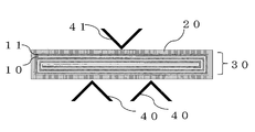
- FIG. 1 is a schematic view showing a method for evaluating wet adhesiveness.
- the battery separator according to the embodiment of the present invention is a porous film made of a polyolefin resin, which contains a vinylidene fluoride-hexafluoropropylene copolymer having a specific molecular weight and a copolymerization ratio and an ionic liquid antistatic agent. It is a laminated layer, and has excellent adhesion to the electrode material and antistatic properties, and is not easily charged with static electricity, so it is excellent in transportability and handleability. Furthermore, it has the feature of retaining excellent rate characteristics and cycle characteristics when used as a separator for non-aqueous secondary batteries, and in particular, a pouch manufactured by processing a battery separator and an electrode material via a dry crimping process. Effective for type batteries.
- the wet adhesive force according to the measurement method described later is 3.0 N or more, preferably 3.5 N or more, and more preferably 4.0 N or more. .. If it is less than 3.0 N, cell deformation occurs due to expansion and contraction of the electrode during the battery cycle test, and long-term reliability is lowered. On the other hand, when the wet adhesive force is 3.0 N or more, cell deformation due to electrode expansion and contraction during the battery cycle test is less likely to occur, and long-term reliability is improved. There is no particular upper limit to the wet adhesive strength, but 30 N is sufficient for wet adhesive strength.
- the separator for a non-aqueous secondary battery according to the embodiment of the present invention is soluble in an ionic liquid antistatic agent, a vinylidene fluoride-hexafluoropropylene copolymer and a vinylidene fluoride-hexafluoropropylene copolymer.
- a resin solution composed of a solvent miscible with water (hereinafter, may be abbreviated as a coating liquid) is applied to a predetermined porous film to form a coating layer, and then the coating layer is formed. Is made porous (formation of a three-dimensional network structure).
- a phase separation aid may be added to the coating liquid. Examples of the phase separation aid include water, ethylene glycol, propylene glycol, tetramethylene glycol, neopentyl glycol and the like.
- the polyolefin porous membrane used in the embodiment of the present invention will be described.
- a resin constituting the polyolefin porous film a polyolefin-based resin is used, and a polyethylene resin, a polypropylene resin, and a mixture thereof are particularly preferable. This is because, in addition to basic characteristics such as electrical insulation and ion permeability, it has a hole closing effect that cuts off the current and suppresses an excessive temperature rise when the battery temperature rises abnormally.
- the resin constituting the polyolefin porous membrane is preferably from the viewpoint of process workability and mechanical strength to withstand various external pressures generated at the time of winding with the electrode, for example, tensile strength, elastic modulus, elongation, and piercing strength.
- the weight average molecular weight is 300,000 or more, more preferably 400,000 or more, and most preferably 500,000 or more.
- the polyolefin component having a weight average molecular weight in the above range is contained in an amount of 50% by mass or more, and more preferably 60% by mass or more.
- the melt viscosity is not too low, and deterioration of mechanical properties when the temperature rises beyond the pore closing temperature can be suppressed, and winding pressure and burrs at the electrode ends can be suppressed even near the pore closing temperature. Can reduce the possibility of melt rupture.
- the phase structure of the porous polyolefin membrane differs depending on the manufacturing method. As long as it is within the range that satisfies the above various characteristics, it is possible to freely have a phase structure according to the purpose by the manufacturing method.
- Methods for producing a porous polyolefin membrane include a foaming method, a phase separation method, a dissolution recrystallization method, a stretch opening method, a powder sintering method, etc. Among these, the phase is considered in terms of homogenization of fine pores and cost.
- the separation method is preferred.
- the polyolefin porous membrane preferably has a function of closing pores (pore closing function) when the charge / discharge reaction is abnormal. Therefore, the melting point (softening point) of the constituent resin is preferably 70 to 160 ° C, more preferably 80 to 140 ° C, and most preferably 100 to 130 ° C. If the temperature is 70 ° C. or higher, the possibility that the hole closing function is exhibited during normal use and the battery becomes unusable can be reduced, and if the temperature is 160 ° C. or lower, the hole closing function is developed before the abnormal reaction sufficiently progresses. Therefore, safety can be ensured.
- the film thickness of the polyolefin porous membrane is preferably 16 ⁇ m or less.
- the upper limit is preferably 9 ⁇ m or less, more preferably 7 ⁇ m or less.
- the lower limit is preferably 4 ⁇ m or more, more preferably 5 ⁇ m or more. If it is 4 ⁇ m or more, it can have practical film strength and pore closing function, and if it is 16 ⁇ m or less, the area per unit volume of the battery case is not restricted, and the high capacity of the battery will be advanced in the future. Suitable for conversion.
- the upper limit of the air permeability resistance (JIS-P8117) of the polyolefin porous membrane is preferably 500 seconds / 100 ccAir or less, more preferably 400 seconds / 100 ccAir or less, most preferably 300 seconds / 100 ccAir or less, and the lower limit is preferably 50. Seconds / 100ccAir or more, more preferably 70 seconds / 100ccAir or more, and most preferably 100 seconds / 100ccAir or more. Sufficient rate characteristics can be obtained when the air permeation resistance is 500 seconds / 100 ccAir or less.
- the upper limit of the porosity of the polyolefin porous membrane is 70% or less, preferably 60% or less, and more preferably 55% or less.
- the lower limit is 30% or more, preferably 35% or more, and more preferably 40% or more.
- the air permeation resistance is higher than 500 seconds / 100 ccAir or the porosity is lower than 30%, it is closely related to ion permeability (charge / discharge operating voltage) and battery life (holding amount of electrolyte). ) Is not sufficient, and if it exceeds these ranges, it may not be possible to fully exert its function as a battery.
- the average pore size of the polyolefin porous membrane has a great influence on the pore closing rate, and is therefore 0.01 to 1.0 ⁇ m, preferably 0.05 to 0.5 ⁇ m, and more preferably 0.1 to 0.3 ⁇ m.
- the average pore size is 0.01 ⁇ m or more, the anchor effect of the vinylidene fluoride-hexafluoropropylene copolymer can be obtained, and sufficient adhesiveness of the porous layer can be obtained.
- the average pore diameter is 1.0 ⁇ m or less, it is possible to suppress the slow response of the pore closing phenomenon to the temperature and reduce the possibility that the pore closing temperature shifts to a higher temperature side due to the temperature rise rate. ..
- the surface of the film was measured by SEM (Scanning Electron Microscope) at an appropriate magnification, and any 10 points were selected on the obtained image, and the pore diameters of those 10 points were selected. It can be calculated from the average value of.
- the porous layer contains a vinylidene fluoride-hexafluoropropylene copolymer having a specific molecular weight and a copolymerization ratio, and plays a role of imparting wet and dry adhesiveness to the electrode material. Therefore, the melting point of the vinylidene fluoride-hexafluoropropylene copolymer constituting the porous layer is preferably 60 ° C. or higher, more preferably 80 ° C. or higher, most preferably 100 ° C. or higher, and the upper limit is preferably 160 ° C. or lower. , More preferably 155 ° C or lower, and most preferably 150 ° C or lower. Within the above range, appropriate wet adhesiveness and dry adhesiveness with the electrode material can be obtained. In particular, when the melting point is 160 ° C. or lower, wet adhesiveness and dry adhesiveness with the electrode material can be obtained.
- the vinylidene fluoride-hexafluoropropylene copolymer used for the porous layer will be described in detail below.
- the lower limit of the hexafluoropropylene unit content in the vinylidene fluoride-hexafluoropropylene copolymer is 0.3 mol% or more, preferably 0.8 mol% or more, more preferably 1.0 mol% or more, and the upper limit is 10 mol% or less. It is preferably 5 mol% or less, more preferably 4 mol% or less, and most preferably 3 mol% or less.
- the lower limit of the weight average molecular weight is 350,000 or more, preferably 500,000 or more, and more preferably 650,000 or more.
- the upper limit is 2 million or less, preferably 1.5 million or less, and more preferably 1.2 million or less.
- the weight average molecular weight is a polystyrene-equivalent value obtained by gel permeation chromatography.
- the content of hexafluoropropylene units is less than 0.3 mol%, sufficient dry adhesiveness may not be obtained. If it exceeds 10 mol%, the three-dimensional network structure of the porous layer is easily deformed. If the molecular weight is less than 350,000, sufficient wet adhesiveness may not be obtained. If it exceeds 2 million, the solubility in a solvent decreases and it becomes difficult to prepare a coating solution.
- the porous layer is formed by interaction with an ionic liquid antistatic agent in the dry pressure bonding step.
- Deformation of the three-dimensional network structure is suppressed, and as a result, excellent rate characteristics can be obtained when incorporated into a battery. That is, by using an ionic liquid antistatic agent and a vinylidene fluoride-hexafluoropropylene copolymer having the ratio and weight average molecular weight of the hexafluoropropylene unit, antistatic property, dry adhesive property, and wet adhesive property are imparted. Not only can these interactions be possible, but deformation of the three-dimensional network structure of the porous layer in the dry pressure bonding step can also be suppressed. This is an unexpected effect.
- the ionic liquid antistatic agent used in the embodiment of the present invention has an affinity for a solvent that dissolves the vinylidene fluoride-hexafluoropropylene copolymer, dissolves in a non-aqueous electrolytic solution, and is further hydrophobic. Is. A commonly used antistatic agent that adsorbs moisture in the air to impart antistatic properties cannot obtain the effect of retaining rate characteristics.
- the ionic liquid antistatic agent used in the embodiment of the present invention is a fluorinated quaternary ammonium salt.
- the fluorine-based quaternary ammonium salt include a quaternary ammonium ion having at least one hydrocarbon group having C4 or more carbon atoms as a cation and a van der Waals volume of 0.08 nm 3 or more as an anion. It preferably has a fluorine-containing anion.
- Fluorine-based quaternary ammonium salt, vinylidene fluoride constituting the porous layer - vinylidene fluoride through interaction with CF 2 chain in hexafluoropropylene copolymer - are considered to be compatible with hexafluoropropylene copolymer
- a quaternary ammonium ion having no hydrocarbon group having C4 or more carbon atoms is used as the cation, the charge density is high and the charge is localized, so that the fluoridene-hexafluoropropylene copolymer weight is high. It is presumed that the interaction with the coalescence becomes excessive and does not uniformly dissolve, and bleed-out is likely to occur.
- the charge density decreases in proportion to the van der Waals volume of the constituent ions, and the charge is delocalized. Therefore, by using a fluorine-containing anion having a van der Waals volume of 0.08 nm 3 or more as an anion, an increase in charge density and localization of electric charge are suppressed, and compatibility is further improved, so that bleed-out is less likely to occur. It is estimated that it will be.
- tetrabutylammonium, tributylmethylammonium, tributylethylammonium, tetrapentylammonium and the like can be used, and tributylmethylammonium is preferable.
- fluorine-containing anions constituting the fluorine-based quaternary ammonium salt N (SO 2 CF 3) 2 -, N (SO 2 F) 2 -, N (SO 2 CF 3) (COCF 3) - , N (SO 2 CF 3 ) (SO 2 C 2 F 5 ) ⁇ , and the like, and N (SO 2 CF 3 ) 2 ⁇ is preferable.
- ionic liquid antistatic agents By using these ionic liquid antistatic agents, not only can antistatic properties be imparted to the battery separator, but also excellent rate characteristics can be maintained when used as a non-aqueous secondary battery separator.
- the present inventors presume the mechanism by which the ionic liquid antistatic agent affects the rate characteristics as follows.
- the porous layer is a resin solution composed of an ionic liquid antistatic agent, a vinylidene fluoride-hexafluoropropylene copolymer, and a solvent that is soluble in the vinylidene fluoride-hexafluoropropylene copolymer and is compatible with water.
- the copolymer is put into a water bath (coagulation bath) to coagulate the vinylidene fluoride-hexafluoropropylene copolymer, washed with water, and dried to form a three-dimensional network structure.
- coagulation bath the solvent dissolves from the coating layer into the coagulation bath, but the ionic liquid antistatic agent used in the embodiment of the present invention is hydrophobic and has low volatility, so that it can be used as a battery separator. Even after this, a part remains in the three-dimensional network structure of the porous layer.
- the ionic liquid antistatic agent remaining in the three-dimensional network structure imparts the effect of imparting elasticity to the porous layer and the effect of filling the pores, and has a specific molecular weight and a specific hexafluoropropylene copolymerization ratio. It is presumed that the effect of suppressing deformation of the porous layer in the dry pressure bonding step can be obtained by the interaction with the vinylidene fluoride-hexafluoropropylene copolymer having both electrode adhesiveness and film strength. This is an effect that cannot be obtained when the inside of the three-dimensional network structure of the porous layer is simply a cavity.
- the vinylidene fluoride-hexafluoropropylene copolymer swells due to the injection of an electrolytic solution in the battery assembly process, and most of the three-dimensional network structure becomes gel-like.
- swelling is suppressed in the portion where the ionic liquid antistatic agent remains. Over time, the ionic liquid antistatic agent is replaced with the electrolytic solution, and the electrolytic solution partially remains in a liquid state.
- the porous layer is an electrolytic solution formed by an ionic liquid antistatic agent.
- the ionic liquid antistatic agent is not contained, and the ion permeability is improved as compared with the case where the entire porous layer is in a gel state.
- the ionic liquid antistatic agent is hydrophobic, it also has the effect of suppressing the adverse effect of moisture on the battery.
- the antistatic agent is hydrophilic, the water adsorbed on the hydrophilic antistatic agent of the battery separator mounted in the battery may react with the electrolytic solution to generate gas.
- the presence of water consumes lithium ions, which reduces the cycle life of the entire battery.
- the method for containing the ionic liquid antistatic agent in the porous layer is not particularly limited as long as the separator according to the embodiment of the present invention can be produced, but for example, it may be added to a coating liquid and mixed sufficiently evenly. Can be done.
- the amount of the ionic liquid antistatic agent added to the total mass of the vinylidene fluoride-hexafluoropropylene copolymer in the coating liquid can be regarded as the content in the porous layer.
- the amount of the ionic liquid antistatic agent added to the total mass of the vinylidene fluoride-hexafluoropropylene copolymer is preferably 0.3 to 30% by mass, more preferably 0.5 to 20% by mass, and further preferably 1. It is 0 to 15% by mass.
- the electric charge generated by the peeling or friction of the separator can be effectively dispersed. If the addition amount is 0.3% or more, a sufficient charge diffusion path can be formed to diffuse the charge generated in the separator and obtain an antistatic effect. Further, when the addition amount is 30% by mass or less, the diffusivity of electric charge can be obtained.
- the vinylidene fluoride-hexafluoropropylene copolymer a hexafluoropropylene copolymer or two or more kinds of vinylidene fluoride-hexafluoropropylene copolymers having different weight average molecular weights may be mixed. Further, another fluororesin such as polytetrafluoroethylene may be added. Since these copolymers have high affinity with non-aqueous electrolytes and high chemical and physical stability with respect to non-aqueous electrolytes, they maintain sufficient affinity with electrolytes even when used at high temperatures. it can.
- Solvents that can be used to dissolve the vinylidene fluoride-hexafluoropropylene copolymer include N, N-dimethylacetamide (DMAc), N-methyl-2-pyrrolidone (NMP), and hexamethyltriamide phosphate (HMPA). ), N, N-dimethylformamide (DMF), dimethyl sulfoxide (DMSO), ⁇ -butyrolactone, chloroform, tetrachloroethane, dichloroethane, 3-chloronaphthalene, parachlorophenol, tetraline, acetone, acetonitrile, etc. It can be freely selected according to the solubility.
- DMAc N-dimethylacetamide
- NMP N-methyl-2-pyrrolidone
- HMPA hexamethyltriamide phosphate
- DMF N-dimethylformamide
- DMSO dimethyl sulfoxide
- ⁇ -butyrolactone
- the solid content concentration of the coating liquid is not particularly limited as long as it can be coated uniformly, but is preferably 2% by mass or more and 50% by mass or less, and more preferably 4% by mass or more and 40% by mass or less.
- the solid content concentration is 2% by mass or more, the obtained porous layer is less likely to become brittle. Further, if it is 50% by mass or less, the thickness of the porous layer can be easily controlled.
- the porous layer preferably contains inorganic particles or heat-resistant polymer particles, and preferably contains inorganic particles.
- the inorganic particles or the heat-resistant polymer particles may be added to the coating liquid.
- the content of particles in the porous layer is preferably 85% by volume or less, more preferably 75% by volume, with the total of vinylidene fluoride-hexafluoropropylene copolymer and particles as 100% by volume. % Or less, more preferably 70% by volume or less.
- the lower limit is preferably 20% by volume or more, more preferably 30% by volume or more, and further preferably 50% by volume or more. If it is 85% by volume or less, the ratio of the polyvinylidene fluoride-based resin to the total volume of the porous layer does not become too small, which not only suppresses the deterioration of the adhesiveness with the electrode material, but also with respect to the porous polyolefin membrane. Sufficient adhesiveness of the vinylidene fluoride-hexafluoropropylene copolymer can be obtained. If it is 20% by volume or more, a sufficient effect of reducing the heat shrinkage rate can be obtained.
- Inorganic particles include calcium carbonate, calcium phosphate, amorphous silica, crystalline glass filler, kaolin, talc, titanium dioxide, alumina, silica-alumina composite oxide particles, barium sulfate, calcium fluoride, lithium fluoride, and zeolite. , Molybdenum sulfide, mica, zeolite and the like.
- the heat-resistant polymer particles include crosslinked polystyrene particles, crosslinked acrylic resin particles, crosslinked methyl methacrylate-based particles, benzoguanamine / formaldehyde condensate particles, melamine / formaldehyde condensate particles, and polytetrafluoroethylene particles. ..
- the porous layer may be laminated on at least one surface of the polyolefin porous membrane, but it may be laminated on both sides of the polyolefin porous membrane. preferable.
- the film thickness of the porous layer is preferably 0.5 to 6 ⁇ m per side, more preferably 1 to 5 ⁇ m, and even more preferably 1 to 4 ⁇ m. If the film thickness is 0.5 ⁇ m or more, sufficient adhesiveness to the electrode material can be obtained, and if it is 6 ⁇ m or less, the winding volume does not become too large, and it is suitable for increasing the capacity of batteries that will be advanced in the future. ing.
- the upper limit of the total thickness of the battery separator obtained by laminating the polyolefin porous membrane and the porous layer is 25 ⁇ m or less, more preferably 20 ⁇ m or less.
- the lower limit is preferably 6 ⁇ m or more, more preferably 7 ⁇ m or more. If the total thickness of the battery separator is 25 ⁇ m or less, a sufficient electrode area that can be filled in the container can be sufficiently secured, and a decrease in capacity can be avoided. Further, if the total thickness of the battery separator is 6 ⁇ m or more, sufficient mechanical strength and insulating properties can be ensured.
- the air permeability resistance of the battery separator is preferably 50 to 600 seconds / 100 ccAir, more preferably 100 to 500 seconds / 100 ccAir, and most preferably 100 to 400 seconds / 100 ccAir. If the air permeability resistance is 50 seconds / 100 ccAir or more, sufficient insulation can be obtained, the possibility of foreign matter clogging, short circuit, or film rupture can be reduced, and if it is 600 seconds / 100 ccAir or less, the film resistance is low. Rate characteristics and cycle characteristics within the range that can be actually used can be obtained.
- the water content of the battery separator is preferably 0 to 1000 ppm, more preferably 0 to 800 ppm, and most preferably 0 to 500 ppm.
- the porous layer is formed by coating a polyolefin porous film with a coating solution composed of an ionic liquid antistatic agent, a vinylidene fluoride-hexafluoropropylene copolymer, a solvent, and if necessary, particles.
- a coating layer is formed, the vinylidene fluoride-hexafluoropropylene copolymer and the solvent are phase-separated, and the polymer is further put into a water bath (coagulation bath) to coagulate the vinylidene fluoride-hexafluoropropylene copolymer and washed with water.
- a three-dimensional network structure is formed by drying.
- Examples of the method of applying the coating liquid onto the porous polyolefin film include a reverse roll coating method, a gravure coating method, a kiss coating method, a roll brushing method, a spray coating method, an air knife coating method, a wire barber coating method, and a pipe doctor. Examples thereof include a method, a blade coating method and a die coating method, and these methods can be performed alone or in combination.
- the coagulation bath preferably contains water as a main component, preferably an aqueous solution containing 1 to 20% by mass of a good solvent for the vinylidene fluoride-hexafluoropropylene copolymer, and more preferably an aqueous solution containing 5 to 15% by mass. ..
- a good solvent include N-methyl-2-pyrrolidone, N, N-dimethylformamide, and N, N-dimethylacetamide.
- the immersion time in the coagulating liquid is preferably 3 seconds or longer. The upper limit is not limited, but 10 seconds is sufficient.
- Water can be used for cleaning.
- the drying can be performed by using hot air of, for example, 100 ° C. or lower.
- the film thickness was measured using a contact type film thickness meter (Digital Micrometer M-30 manufactured by Sony Manufacturing Co., Ltd.).
- aqueous solution containing 1.5 parts by mass of carboxymethyl cellulose was added to 96.5 parts by mass of artificial graphite and mixed, and 2 parts by mass of styrene-butadiene latex as a solid content was added and mixed to obtain a negative electrode mixture-containing slurry.
- This negative electrode mixture-containing slurry is uniformly applied to both sides of a negative electrode current collector made of copper foil having a thickness of 8 ⁇ m and dried to form a negative electrode layer, and then compression-molded by a roll press to collect current.
- a negative electrode was prepared by setting the density of the negative electrode layer excluding the body to 1.5 g / cm 3 .
- the negative electrode 11 created above (161 mm in the mechanical direction ⁇ 30 mm in the width direction) and the prepared battery separator 10 (160 mm in the mechanical direction ⁇ 34 mm in the width direction) are overlapped with each other to form a metal plate (length 300 mm, width 25 mm, thickness 1 mm).
- the battery separator 10 and the negative electrode 11 were wound around the winding core so that the battery separator 10 was inside, and the metal plate was pulled out to obtain a test winding body 30.
- the test wound body had a length of about 34 mm and a width of about 28 mm.
- each of the above-mentioned reference numerals represents a reference numeral in FIG.
- test winding body 30 was placed in a bag-shaped laminated film 20 in which three of the four sides were welded. .. 500 ⁇ L of an electrolytic solution prepared by dissolving LiPF 6 at a ratio of 1 mol / L in a solvent in which ethylene carbonate and ethyl methyl carbonate are mixed at a volume ratio of 3: 7 is injected through the opening of the laminate film 20 in a glove box, and a test roll is used. The body 30 was impregnated, and one side of the opening was sealed with a vacuum sealer.
- test winding body 30 enclosed in the laminate film 20 is sandwiched between two gaskets (thickness 1 mm, 5 cm ⁇ 5 cm), and a precision heating and pressurizing device (manufactured by Shinto Kogyo Co., Ltd., CYPT-10).
- the pressure was increased at 98 ° C. and 0.6 MPa for 2 minutes, and the mixture was allowed to cool at room temperature (25 ° C.).
- the wet adhesive strength of the test winding body 30 after pressurization was measured using a universal testing machine (AGS-J, manufactured by Shimadzu Corporation) while being sealed in the laminate film 20. Details will be described below with reference to FIG.
- Two aluminum L-shaped angles 40 are arranged in parallel so that the 90 ° part faces up, with the ends aligned, and the 90 ° part is the fulcrum. It was fixed so that the distance between them was 15 mm.
- the aluminum L-shaped angle 40 is aligned with the midpoint of the widthwise side (about 28 mm) of the test winding body at the 7.5 mm point, which is the middle of the distance between the fulcrums of the two aluminum L-shaped angles 40.
- the test winding body 30 was arranged so as not to protrude from the side in the length direction of.
- the side (about 34 mm) in the length direction of the test winding body protrudes from the side in the length direction of the aluminum L-shaped angle 41 (thickness 1 mm, 10 mm ⁇ 10 mm, length 4 cm).
- a total of three test winding bodies were measured at a load speed of 0.5 mm / min, and the average value of the obtained maximum test forces was taken as the wet adhesive force.
- a double-sided tape having a width of 1 cm is attached to the negative electrode side of the laminate of the negative electrode and the separator, and the other side of the double-sided tape is placed on a SUS plate (thickness 3 mm, length 150 mm ⁇ width 50 mm) in the mechanical direction of the separator. And SUS plate length direction are parallel to each other. This was used as a test piece.
- a separator was sandwiched between load cell side chucks using a universal testing machine (AGS-J manufactured by Shimadzu Corporation), and a 180-degree peeling test was performed at a test speed of 300 mm / min. The value obtained by averaging the measured values of the strokes from 20 mm to 70 mm during the peeling test was taken as the peeling force of the peeling test piece. A total of three peeling test pieces were measured, and the value obtained by converting the average value of the peeling force into a width was defined as the peeling force during drying (N / m).
- the peeling force at the time of drying is preferably 2 N / m or more, more preferably 4 N / m or more, and further preferably 6 N / m or more.
- the upper limit is not particularly set, but if it is 50 N / m or less, it is preferable that the separator wound in a reel shape can be stored without being adhered to each other.
- Judgment of the evaluation result is that the peeling force at the time of drying is less than 2 N / m and fails (x), 2 N / m or more and less than 4 N / m passes (C), and 4 N / m or more and less than 6 N / m is good (B). It was evaluated as excellent (A) at 6 N / m or more.
- Lithium cobalt composite oxide LiCoO 2 as the positive electrode active material, acetylene black as the conductive material, and polyvinylidene fluoride (PVDF) as a binder are mixed at a mass ratio of 93.5: 4.0: 2.5 to form a solvent.
- a slurry was prepared by mixing and dispersing in N-methylpyrrolidone (NMP). This slurry was applied to both sides of a 12 ⁇ m-thick aluminum foil serving as a positive electrode current collector, dried, and then rolled with a roll press. The rolled product was slit to a width of 30 mm to obtain a positive electrode.
- NMP N-methylpyrrolidone
- a slurry was prepared by mixing and dispersing artificial graphite as a negative electrode active material, carboxymethyl cellulose as a binder, and styrene-butadiene copolymer latex in purified water so as to have a mass ratio of 98: 1: 1.
- This slurry was applied to both sides of a copper foil having a thickness of 10 ⁇ m as a negative electrode current collector, dried, and then rolled by a roll press. The rolled product was slit to a width of 33 mm to form a negative electrode.
- the charging / discharging condition was a current value of 300 mA, and after charging with a constant current to a battery voltage of 4.2 V, constant voltage charging was performed with a battery voltage of 4.2 V until reaching 15 mA. After a 10-minute pause, a constant current discharge was performed at a current value of 300 mA to a battery voltage of 3.0 V, followed by a 10-minute pause. The above charging and discharging were carried out for 3 cycles to prepare a test secondary battery having a battery capacity of 300 mAh.
- the test secondary battery prepared in the above (manufacturing of the battery) is used, and after constant current charging with a current value of 1.0C up to a battery voltage of 4.2V, the rate characteristic is 0.05C at a battery voltage of 4.2V. Constant voltage charging was performed until the current value was reached, and discharge (constant current discharge) was performed until the battery voltage reached 3.0 V at a current value of 0.2 C, and the discharge capacity was measured. Then, after charging to 4.2V again by the above procedure, discharge (constant current discharge) until the battery voltage reaches 3.0V at a current value of 5C, measure the discharge capacity, and measure the discharge capacity at 0.2C.
- the ratio of the discharge capacity at 5C to the discharge capacity was defined as the discharge capacity ratio.
- This discharge capacity ratio is preferably 80% or more, more preferably 82% or more, still more preferably 85% or more.
- the upper limit is not particularly set, but it is preferably 98% or less because there is a concern that the self-discharge characteristics may deteriorate due to a decrease in strength. Judgment of the evaluation result is rejected when the discharge capacity ratio is less than 80% (x), passed when 80% or more and less than 82% (C), good when 82% or more and less than 85% (B), and excellent when 85% or more (A). ).
- the cycle characteristic test was carried out by placing the produced lithium-ion battery in a constant temperature bath (Yamato Scientific Co., Ltd., DNE-610) and connecting it to a charge / discharge tester (TOSCAT-3000) manufactured by Toyo System.
- the test temperature of the cycle characteristic test is 30 ° C.
- the charging condition is that a current of 1C is passed in the constant current (CC) mode until the voltage of the lithium ion battery reaches 4.35V, and after reaching 4.35V, the constant voltage ( Charging was performed in the CV) mode until the charging current reached 0.05 C.
- a current of 0.5 C was passed in the constant current mode, and the cutoff voltage was set to 3 V.
- the ratio of the discharge capacity after 500 cycles to the initial discharge capacity at 0.2C was defined as the cycle characteristic discharge capacity ratio.
- the discharge capacity ratio is not particularly set, but is preferably 78% or more, more preferably 80% or more, and further preferably 82% or more.
- the evaluation results are judged as rejected when the discharge capacity ratio is less than 78% (x), passed when 78% or more and less than 80% (C), good when 80% or more and less than 82% (B), and (excellent) when 82% or more. It was designated as A.
- Moisture content The water content of the separators prepared in the following Examples and Comparative Examples was measured by using the Karl Fischer titration method.
- Moisture vaporization conditions Equipment: Moisture vaporizer (ADP-611, manufactured by Kyoto Electronics Industry Co., Ltd.) Atmosphere ... N2 (200mL / min) Temperature: 150 ° C Time ... 10 minutes Sample volume: Approximately 1.0 g Moisture measurement conditions: Measurement method: Coulometric titration method Device: MKC-610, manufactured by Kyoto Electronics Industry Co., Ltd. Reagent: Chemaqua anode solution AGE, Chemaqua cathode solution CGE (manufactured by Kyoto Electronics Industry Co., Ltd.).
- Example 1 Preparation of coating liquid 5% by mass of vinylidene fluoride-hexafluoropropylene copolymer (PVDF-HFP, weight average molecular weight 1.2 million, ratio of hexafluoropropylene monomer unit is 0.6 mol%) with respect to N-methyl-2-pyrrolidone
- PVDF-HFP vinylidene fluoride-hexafluoropropylene copolymer
- N-methyl-2-pyrrolidone To obtain a fluororesin solution in which the PVDF-HFP was completely dissolved.
- the alumina particles were added to the fluororesin solution while stirring with a mechanical stirrer so that the volume of the alumina particles having an average particle diameter of 1 ⁇ m and the volume of PVDF-HFP were 50:50, and then Dynomill (manufactured by Simmal Enterprises).
- alumina particle-dispersed fluororesin solution It was completely dispersed using a Dynomill Multilab) to prepare an alumina particle-dispersed fluororesin solution.
- a hydrophobic ionic liquid antistatic agent tri-N-butylmethylammonium
- Tri-N-butylmethylammonium was added to the alumina particle-dispersed fluororesin solution so as to be 6% by mass based on the mass of PVDF-HFP contained in the prepared alumina particle-dispersed fluororesin solution.
- Bistrifluoromethanesulfonimide (Bu 3 MeNTFSA) was added while stirring with a mechanical stirrer to obtain a coating solution.
- the temperature of the coating liquid was adjusted so as to be in the range of 30 to 35 ° C.
- the coating liquid was kept sealed so as not to come into contact with the outside air until the time of coating.
- Example 2 In the preparation of the coating liquid, the vinylidene fluoride-hexafluoropropylene copolymer has a weight average molecular weight of 1.2 million and the proportion of hexafluoropropylene monomer units is 1.0 mol%.
- a battery separator was obtained in the same manner as in Example 1 except that it was replaced with.
- Example 3 In the preparation of the coating liquid, the vinylidene fluoride-hexafluoropropylene copolymer has a weight average molecular weight of 1.2 million and the proportion of hexafluoropropylene monomer units is 2.0 mol%.
- a battery separator was obtained in the same manner as in Example 1 except that it was replaced with.
- the vinylidene fluoride-hexafluoropropylene copolymer is a vinylidene fluoride-hexafluoropropylene copolymer having a weight average molecular weight of 1.2 million and a hexafluoropropylene monomer unit ratio of 3.0 mol%.
- a battery separator was obtained in the same manner as in Example 1 except that it was replaced with.
- Example 5 In the preparation of the coating liquid, the vinylidene fluoride-hexafluoropropylene copolymer has a weight average molecular weight of 1.2 million and the ratio of hexafluoropropylene monomer units is 4.0 mol%.
- a battery separator was obtained in the same manner as in Example 1 except that it was replaced with.
- Example 6 In the preparation of the coating liquid, the vinylidene fluoride-hexafluoropropylene copolymer has a weight average molecular weight of 1.2 million and the proportion of hexafluoropropylene monomer units is 5.0 mol%.
- a battery separator was obtained in the same manner as in Example 1 except that it was replaced with.
- Example 7 In the preparation of the coating liquid, the vinylidene fluoride-hexafluoropropylene copolymer has a weight average molecular weight of 1.2 million and the ratio of hexafluoropropylene monomer units is 7.0 mol%.
- a battery separator was obtained in the same manner as in Example 1 except that it was replaced with.
- Example 8 In the preparation of the coating liquid, the vinylidene fluoride-hexafluoropropylene copolymer has a weight average molecular weight of 1.2 million and the ratio of hexafluoropropylene monomer units is 10.0 mol%.
- a battery separator was obtained in the same manner as in Example 1 except that it was replaced with.
- Example 9 In the preparation of the coating liquid, the vinylidene fluoride-hexafluoropropylene copolymer has a weight average molecular weight of 350,000 and the proportion of hexafluoropropylene monomer units is 1.0 mol%.
- a battery separator was obtained in the same manner as in Example 1 except that it was replaced with.
- Example 10 In the preparation of the coating liquid, the vinylidene fluoride-hexafluoropropylene copolymer has a weight average molecular weight of 1.8 million and the proportion of hexafluoropropylene monomer units is 1.0 mol%.
- a battery separator was obtained in the same manner as in Example 1 except that it was replaced with.
- Example 11 In the preparation of the coating liquid, the vinylidene fluoride-hexafluoropropylene copolymer has a weight average molecular weight of 1.2 million and the proportion of hexafluoropropylene monomer units is 1.0 mol%.
- a coating solution was obtained in the same manner as in Example 1 except that alumina particles were not used, and the thickness of the porous layer was adjusted to obtain a battery separator having a final thickness of 8 ⁇ m.
- the vinylidene fluoride-hexafluoropropylene copolymer is a vinylidene fluoride-hexafluoropropylene copolymer having a weight average molecular weight of 1.2 million and a hexafluoropropylene monomer unit ratio of 1.0 mol%.
- a separator for a battery was obtained in the same manner as in Example 1 except that the volume of alumina particles and the volume of PVDF-HFP were 80:20.
- the vinylidene fluoride-hexafluoropropylene copolymer is a vinylidene fluoride-hexafluoropropylene copolymer having a weight average molecular weight of 1.2 million and a hexafluoropropylene monomer unit ratio of 1.0 mol%.
- a separator for a battery was obtained in the same manner as in Example 1 except that a hydrophobic ion liquid type antistatic agent was blended so as to be 3% by mass based on the mass of PVDF-HFP contained in the alumina particle-dispersed fluororesin solution. It was.
- the vinylidene fluoride-hexafluoropropylene copolymer is a vinylidene fluoride-hexafluoropropylene copolymer having a weight average molecular weight of 1.2 million and a hexafluoropropylene monomer unit ratio of 1.0 mol%.
- a battery separator was obtained in the same manner as in Example 1 except that the hydrophobic ion liquid type antistatic agent was blended so as to be 14% by mass based on the mass of PVDF-HFP contained in the alumina particle-dispersed fluororesin solution. It was.
- Example 15 In the preparation of the coating liquid, the vinylidene fluoride-hexafluoropropylene copolymer has a weight average molecular weight of 1.2 million and the proportion of hexafluoropropylene monomer units is 1.0 mol%.
- a coating liquid was obtained in the same manner as in Example 1 except that the thickness was changed to, a polyethylene porous film having a thickness of 5 ⁇ m and an air permeation resistance of 100 sec / 100 ccAir was used, and the thickness of the porous layer was adjusted to a final thickness of 9 ⁇ m.
- a separator for a battery was obtained in the same manner as in Example 1 except for the above.
- Example 16 In the preparation of the coating liquid, the vinylidene fluoride-hexafluoropropylene copolymer has a weight average molecular weight of 1.2 million and the proportion of hexafluoropropylene monomer units is 1.0 mol%.
- a coating liquid was obtained in the same manner as in Example 1 except that the thickness was changed to, a polyethylene porous film having a thickness of 12 ⁇ m and an air permeation resistance of 170 sec / 100 ccAir was used, and the thickness of the porous layer was adjusted to a final thickness of 15 ⁇ m. A battery separator was obtained.
- Example 17 In preparation of the coating solution, except for changing the hydrophobic ionic liquid antistatic agent to tetra -N- pentyl ammonium bis trifluoromethane sulfonimide ((C 5 H 11) 4 NTFSA) in the same manner as in Example 1 battery Separator was obtained.
- Example 18 A battery separator was obtained in the same manner as in Example 1 except that the hydrophobic ionic liquid antistatic agent was replaced with tri-N-butylmethylammonium bisfluorosulfonylimide (Bu 3 MeNFSA) in the preparation of the coating liquid. ..
- the vinylidene fluoride-hexafluoropropylene copolymer has a weight average molecular weight of 1.2 million and the proportion of hexafluoropropylene monomer units is 1.0 mol%.
- a separator for a battery was obtained in the same manner as in Example 1 except that a hydrophobic ion liquid type antistatic agent was not used and an alumina particle-dispersed fluororesin solution was used as a coating liquid.
- Comparative Example 2 A battery separator was obtained in the same manner as in Example 1 except that the vinylidene fluoride-hexafluoropropylene copolymer was replaced with homopolyvinylidene fluoride in the preparation of the coating liquid.
- the vinylidene fluoride-hexafluoropropylene copolymer has a weight average molecular weight of 300,000 and a hexafluoropropylene monomer unit ratio of 1.0 mol% of vinylidene fluoride-hexafluoropropylene copolymer weight.
- a battery separator was obtained in the same manner as in Example 1 except that the mixture was replaced with a coalesced mixture.
- the vinylidene fluoride-hexafluoropropylene copolymer has a weight average molecular weight of 1.2 million and a hexafluoropropylene monomer unit ratio of 12.0 mol% of vinylidene fluoride-hexafluoropropylene copolymer weight.
- a battery separator was obtained in the same manner as in Example 1 except that the mixture was replaced with a coalesced mixture.
- Comparative Example 5 A battery separator was obtained in the same manner as in Example 1 except that the hydrophobic ionic liquid antistatic agent was replaced with tetrapropylammonium tetrafluoroborate (Pr 4 NBF 4 ) in the preparation of the coating liquid.
- the hydrophobic ionic liquid antistatic agent was replaced with tetrapropylammonium tetrafluoroborate (Pr 4 NBF 4 ) in the preparation of the coating liquid.
- Comparative Example 6 A battery separator was obtained in the same manner as in Example 1 except that the hydrophobic ionic liquid antistatic agent was replaced with tri-N-butylmethylammonium hexafluorophosphorate (Bu 3 MeNPF 6 ) in the preparation of the coating liquid. It was.
- the separator for a non-aqueous secondary battery of the present invention is excellent in adhesiveness to an electrode material and antistatic property, and can be suitably used particularly when an electrode and a battery separator are superposed at a high speed to manufacture an electrode body. .. Furthermore, by incorporating a hydrophobic ionic liquid antistatic agent that dissolves in the electrolytic solution in the porous layer containing the vinylidene fluoride-hexafluoropropylene copolymer, not only antistatic properties can be obtained, but also the dryness of the battery assembly process can be obtained. In the crimping process, deformation (crushing) of the porous structure of the porous layer can be suppressed to a minimum, and as a result, excellent rate characteristics and cycle characteristics can be maintained after battery assembly.
Landscapes
- Chemical & Material Sciences (AREA)
- Chemical Kinetics & Catalysis (AREA)
- Electrochemistry (AREA)
- General Chemical & Material Sciences (AREA)
- Engineering & Computer Science (AREA)
- Manufacturing & Machinery (AREA)
- Physics & Mathematics (AREA)
- Condensed Matter Physics & Semiconductors (AREA)
- General Physics & Mathematics (AREA)
- Inorganic Chemistry (AREA)
- Cell Separators (AREA)
Abstract
本発明は、ポリオレフィン多孔質膜と、前記ポリオレフィン多孔質膜の少なくとも一方の面に積層された多孔層とを備える非水二次電池用セパレータであって、多孔層はフッ化ビニリデン-ヘキサフルオロプロピレン共重合体と非水電解液に溶解する疎水性イオン液体型帯電防止剤を含み、前記フッ化ビニリデン-ヘキサフルオロプロピレン共重合体は、0.3mol%以上10mol%以下のヘキサフルオロプロピレン単位を有し、重量平均分子量が35万以上200万以下であり、前記非水電解液に溶解する疎水性イオン液体型帯電防止剤は、カチオンとして炭素数がC4以上である炭化水素基を1つ以上有する四級アンモニウムイオンを含むフッ素系四級アンモニウム塩である非水二次電池用セパレータに関する。
Description
本発明は、ポリオレフィン系樹脂からなる多孔質膜に対してポリフッ化ビニリデン系樹脂を含む多孔層を積層した、電極材料との接着性に優れ、かつ、帯電防止性を有する電池用セパレータであり、特にリチウムイオン電池用セパレータとして有用な非水二次電池用セパレータおよび非水二次電池に関するものである。
熱可塑性樹脂からなる多孔質膜は、物質の分離や選択透過及び隔離のための材料等として広く用いられている。例えば、リチウム二次電池、ニッケル-水素電池、ニッケル-カドミウム電池、ポリマー電池に用いる電池用セパレータや、電気二重層コンデンサ用セパレータ、逆浸透濾過膜、限外濾過膜、精密濾過膜等の各種フィルター、透湿防水衣料、医療用材料等で用いられている。特にポリエチレン多孔質膜は、リチウムイオン二次電池用セパレータとして好適に使用されているが、その理由は、電気絶縁性に優れる、電解液含浸によりイオン透過性を有する、耐電解液性・耐酸化性に優れるという特徴だけでなく、電池異常昇温時の120~150℃程度の温度において電流を遮断し過度の昇温を抑制する孔閉塞効果をも備えているためである。しかしながら、ポリエチレン多孔質膜は、何らかの原因で孔閉塞後も昇温が続く場合、膜を構成する融解したポリエチレンの粘度低下及び膜の収縮により、ある温度で破膜を生じることがある。また、一定高温下に放置すると、融解したポリエチレンの粘度低下及び膜の収縮により、ある時間経過後に破膜を生じる可能性がある。この現象は、ポリエチレン多孔質膜に限定された現象ではなく、他の熱可塑性樹脂を用いた場合においても、その多孔質膜を構成する樹脂の融点以上では避けることができない。
特にリチウムイオン電池用セパレータは、電池特性、電池生産性及び電池安全性に深く関わっており、優れたイオン透過性、電極材料との接着性、孔閉塞特性(シャットダウン特性)、溶融破膜防止特性(メルトダウン防止特性)、帯電防止性等が要求される。電極材料との接着性を付与するためには、ポリフッ化ビニリデン系樹脂を含む多孔層を積層する方法が好適に用いられる。
電極材料との接着性が求められるのは以下の理由による。
電池内において、電解液が存在する状態での電極材料と電池用セパレータの接着性(以下、ウェット接着性と記す場合がある。)は、電池特性に深く関わっており、優れた接着性が求められる。
さらに、一般に電極材料とセパレータは搬送工程中において50℃~100℃程度で加熱し、ポリフッ化ビニリデン系樹脂を軟化させ、加圧によって接着させる(ドライ圧着工程と記す。)。
電極材料と電池用セパレータからなる電極体を搬送する際、各部材が十分に接着されていなければ電極とセパレータが剥がれてしまい歩留りよく搬送させることができない。また、電池の大型化により顕在化し、さらに歩留り悪化が懸念される。そのため、搬送中に電極から剥離しにくくするために、セパレータには電極との接着性(以下、ドライ接着性と記す。)が求められる。
電極材料と電池用セパレータからなる電極体を搬送する際、各部材が十分に接着されていなければ電極とセパレータが剥がれてしまい歩留りよく搬送させることができない。また、電池の大型化により顕在化し、さらに歩留り悪化が懸念される。そのため、搬送中に電極から剥離しにくくするために、セパレータには電極との接着性(以下、ドライ接着性と記す。)が求められる。
帯電防止性が求められるのは以下の理由による。ポリフッ化ビニリデン系樹脂は、帯電しやすい性質を有しており、摩擦や剥離などにより強い静電気を有するといった特性を示す。一方、電池用セパレータは、リール状の巻回体として流通しており、正負極間に挿入して電極群を構成する際にこの巻回体が巻き解かれる。そのため、脱落しやすい電極材料である活物質がセパレータの静電気によって、再付着し、巻回体としたとき、脱落した活物質凝集物が電極と電池用セパレータ間に巻き込まれ、短絡を誘発しやすくなる場合がある。今後進むであろう電池の高容量化に伴って、ポリオレフィン多孔質膜の厚さはより薄くなる傾向にあり、この耐短絡性の低下傾向はより顕著になることが予想される。さらに、静電気によって、滑りにくくなり、電池製造の工程でハンドリング性が問題となる場合もある。仮に、セパレータから静電気を除去する静電気除去工程を設けるとしても、電池の製造工程全般にわたって静電気を除去することは難しい。そのため、これまでに多孔層に様々な帯電防止剤を添加する検討がなされている。
特許文献1では、フッ化ビニリデン-ヘキサフロロプロピレン共重合体をジメチルアセトアミド/トリプロピレングリコール混合溶媒に溶解して得た塗工液をポリエチレン多孔質膜に塗工し、次いで凝固液に浸漬することで固化させて、これを水洗、乾燥することで非水系二次電池用セパレータを得ている。
特許文献2では、多孔質ポリエチレン膜を基材として、表面にアラミド樹脂を塗着し、アラミド-多孔質ポリエチレン積層膜に帯電防止剤としてNNN-トリメチル-n-(2-ヒドロキシ-3-メタクリロイルオキシプロピル)アンモニウムクロライドの50質量%水溶液をスプレー塗工したセパレータを例示している。
特許文献3では、ポリエチレン多孔質膜にポリフッ化ビニリデン系樹脂とアセチレンブラックを混合させた塗工液を塗工し非水系二次電池用セパレータを得ている。
特許文献4では、ポリエチレン多孔質膜にフッ化ビニリデン樹脂(重量平均分子量:約30万、ホモポリマー)に帯電防止機能を付与するためにポリエーテルエステルアミドおよびLiN(CF3SO2)2を含有する塗液を塗工し、貧溶媒中に浸漬して電子部品用セパレータを得ている。
特許文献5では、分離膜基材として、厚み20μmのポリエチレンフィルムを使用して、ポリフッ化ビニリデン(PVDF)と帯電防止剤としてフッ素系四級アンモニウム塩を用いたコーティング分離膜が開示されており、具体的にフッ素系四級アンモニウム塩としてテトラエチルアンモニウムヘキサフルオロホスフェートが例示されている。
特許文献1の電池用セパレータは帯電防止性を有するものではない。
特許文献2~4の電池用セパレータは静電気の発生は抑制されているものの電極材料とのドライ接着性及びウェット接着性とレート特性を満足するものはなかった。
ここで、本明細書でいうレート特性とは特定放電条件における公称バッテリ容量に対する放電容量の比(放電容量(Ah)/公称容量(Ah))であり、バッテリの放電特性を表わす。例えば、公称20Ahの容量のバッテリを1Cの放電レートで放電するとは、一定温度で20A放電電流にて放電することを意味し、規定電圧に到達したときまでの放電容量(Ah)から1Cのレート特性を求めることができる。
レート特性はこの値が大きいほど充放電特性に優れていることを示す。なお、レート特性は活物質の他、セルの内部抵抗による電圧ドロップの影響も受ける。
本発明は上記事情に鑑みてなされたものであり、電極材料との接着性及び帯電防止性に優れ、さらに、非水二次電池に用いた際に優れたレート特性及びサイクル特性を保持できる非水二次電池用セパレータを提供することを目的とする。
本発明は、以下の構成を有するものである。
本発明の実施形態にかかる非水二次電池用セパレータ(以下、単に電池用セパレータと記載する場合もある。)は、ポリオレフィン多孔質膜と、前記ポリオレフィン多孔質膜の少なくとも一方の面に積層された多孔層とを備える非水二次電池用セパレータであって、前記多孔層はフッ化ビニリデン-ヘキサフルオロプロピレン共重合体と非水電解液に溶解する疎水性イオン液体型帯電防止剤を含み、前記フッ化ビニリデン-ヘキサフルオロプロピレン共重合体は0.3mol%以上10mol%以下のヘキサフルオロプロピレン単位を有し、重量平均分子量が35万以上200万以下であり、前記非水電解液に溶解する疎水性イオン液体型帯電防止剤は、カチオンとして炭素数がC4以上である炭化水素基を1つ以上有する四級アンモニウムイオンを含むフッ素系四級アンモニウム塩である。
本発明の実施形態にかかる非水二次電池用セパレータは、アニオンとしてファンデルワールス体積が0.08nm3以上であるフッ素含有アニオンを含むことが好ましい。
本発明の実施形態にかかる電池用セパレータは前記非水電解液に溶解する疎水性イオン液体型帯電防止剤を、前記フッ化ビニリデン-ヘキサフルオロプロピレン共重合体に対し0.3~30質量%含有することが好ましい。
本発明の実施形態にかかる電池用セパレータは前記多孔層に無機粒子を含むことが好ましい。
本発明の実施形態にかかる電池用セパレータは前記ポリオレフィン多孔質膜の厚さが16μm以下であることが好ましい。
本発明の実施形態にかかる電池用セパレータは前記ポリオレフィン多孔質膜の厚さが7μm以下であることが好ましい。
また本発明の実施形態にかかる非水二次電池は、本発明の非水二次電池用セパレータを用いたことを特徴とするものである。
本発明の非水二次電池用セパレータは電極材料との接着性と帯電防止性に優れ、特に高速で電極と電池用セパレータを重ね合わせて電極体を製造する場合に好適に使用することができる。さらにフッ化ビニリデン-ヘキサフルオロプロピレン共重合体を含む多孔層に電解液に溶解する疎水性イオン液体型帯電防止剤(以下、イオン液体型帯電防止剤と略記する場合がある。)を含有させることによって帯電防止性が得られることのみならず、非水二次電池に用いた際に電池組み立て工程のドライ圧着工程において多孔層の多孔構造変形(潰れ)を最小限に抑制することができ、結果として、電池組み立て後、優れたレート特性及びサイクル特性を保持できる。
なお、本発明でいう疎水性とは水に対して撥水性を有するか、23℃における水に対する溶解度が1質量%以下であることを意味する。
本発明の実施形態にかかる電池用セパレータは、ポリオレフィン系樹脂からなる多孔質膜に特定の分子量と共重合比を有するフッ化ビニリデン-ヘキサフルオロプロピレン共重合体とイオン液体型帯電防止剤を含む多孔層を積層したものであり、電極材料との接着性と帯電防止性に優れ、静電気を帯びにくいため搬送性、ハンドリング性に優れる。さらに非水二次電池用セパレータとして用いたときに優れたレート特性及びサイクル特性を保持するという特徴を有しており、特に電池用セパレータと電極材料をドライ圧着工程を経由して製造されるパウチ型電池に効果を発揮する。
ここで電極材料とのウェット接着性に優れるとは、後述する測定方法によるウェット接着力が3.0N以上であることを意味し、好ましくは3.5N以上、さらに好ましくは4.0N以上である。3.0N未満では電池サイクル試験時に、電極の膨張収縮に伴うセル変形が生じ、長期信頼性が低下する。一方、ウェット接着力3.0N以上では、電池サイクル試験時の電極膨張収縮に伴うセル変形が生じにくくなり、長期信頼性が向上する。ウェット接着力の上限は特にないが、30Nもあればウェット接着性として十分である。
本発明の実施形態にかかる非水二次電池用セパレータは、イオン液体型帯電防止剤とフッ化ビニリデン-ヘキサフルオロプロピレン共重合体とフッ化ビニリデン-ヘキサフルオロプロピレン共重合体に対して可溶で且つ水と混和する溶媒で構成される樹脂溶液(以下、塗工液と略記する場合がある。)を所定の多孔質膜に塗工して塗工層を形成し、次いで、該塗工層を多孔化(三次元網目構造の形成)させることによって得られる。必要に応じて塗工液に相分離助剤を添加しても良い。相分離助剤としては、水、エチレングリコール、プロピレングリコール、テトラメチレングリコール、ネオペンチルグリコールなどが挙げられる。
まず、本発明の実施形態で用いるポリオレフィン多孔質膜について説明する。ポリオレフィン多孔質膜を構成する樹脂としては、ポリオレフィン系樹脂が使用され、特にポリエチレン樹脂、ポリプロピレン樹脂、およびその混合物が好ましい。電気絶縁性、イオン透過性などの基本特性に加え、電池が異常昇温した際に、電流を遮断し過度の昇温を抑制する孔閉塞効果を具備しているからである。
さらに、ポリオレフィン多孔質膜を構成する樹脂は、工程作業性および電極との巻回時に生じる様々な外圧に耐える機械強度、例えば、引っ張り強度、弾性率、伸度、突き刺し強度の点から、好ましくは重量平均分子量が30万以上、さらに好ましくは40万以上、最も好ましくは50万以上である。なお、これらの樹脂を用いる際は、上記範囲の重量平均分子量を有するポリオレフィン成分が50質量%以上含有されていることが好ましく、60質量%以上含有されていることがさらに好ましい。上記範囲の含有量であれば、溶融粘度が低すぎず、孔閉塞温度を超えて昇温した際の機械物性の低下を抑制でき、孔閉塞温度付近でも巻回圧力や電極端部のバリなどによって溶融破膜が起こる可能性を低減できる。
ポリオレフィン多孔質膜の相構造は、製法によって異なる。上記の各種特徴を満足する範囲内ならば、製法により目的に応じた相構造を自由に持たせることができる。
ポリオレフィン多孔質膜の製造方法としては、発泡法、相分離法、溶解再結晶法、延伸開孔法、粉末焼結法などがあり、これらの中では微細孔の均一化、コストの点で相分離法が好ましい。
ポリオレフィン多孔質膜の製造方法としては、発泡法、相分離法、溶解再結晶法、延伸開孔法、粉末焼結法などがあり、これらの中では微細孔の均一化、コストの点で相分離法が好ましい。
ポリオレフィン多孔質膜は、充放電反応の異常時に孔が閉塞する機能(孔閉塞機能)を有することが好ましい。従って、構成する樹脂の融点(軟化点)は、好ましくは70~160℃、さらに好ましくは80~140℃、最も好ましくは100~130℃である。70℃以上であれば、正常使用時に孔閉塞機能が発現して電池が使用不可になる可能性を低減でき、160℃以下であれば異常反応が十分に進行する前に孔閉塞機能が発現するため、安全性を確保できる。
ポリオレフィン多孔質膜の膜厚は16μm以下であることが好ましい。上限は9μm以下が好ましく、より好ましくは7μm以下である。下限は4μm以上が好ましく、より好ましくは5μm以上である。4μm以上であれば実用的な膜強度と孔閉塞機能を保有させることができ、16μm以下であれば、電池ケースの単位容積当たりの面積が制約されず、今後、進むであろう電池の高容量化に適している。
ポリオレフィン多孔質膜の透気抵抗度(JIS-P8117)の上限は好ましくは500秒/100ccAir以下、さらに好ましくは400秒/100ccAir以下、最も好ましくは300秒/100ccAir以下であり、下限は好ましくは50秒/100ccAir以上、さらに好ましくは70秒/100ccAir以上、最も好ましくは100秒/100ccAir以上である。透気抵抗度が500秒/100ccAir以下であれば十分なレート特性が得られる。
ポリオレフィン多孔質膜の空孔率の上限は70%以下、好ましくは60%以下、さらに好ましくは55%で以下ある。下限は30%以上、好ましくは35%以上、さらに好ましくは40%以上である。透気抵抗度が500秒/100ccAirより高くても、空孔率が30%よりも低くても、イオン透過性(充放電作動電圧)、電池の寿命(電解液の保持量と密接に関係する)において十分ではなく、これらの範囲を超えた場合、電池としての機能を十分に発揮することができなくなる可能性がある。一方で、50秒/100ccAirよりも透気抵抗度が低くても、空孔率が70%よりも高くても、十分な機械的強度と絶縁性が得られず、充放電時に短絡が起こる可能性が高くなる。
ポリオレフィン多孔質膜の平均孔径は、孔閉塞速度に大きく影響を与えるため、0.01~1.0μm、好ましくは0.05~0.5μm、さらに好ましくは0.1~0.3μmである。平均孔径が0.01μm以上であれば、フッ化ビニリデン-ヘキサフルオロプロピレン共重合体のアンカー効果が得られ、十分な多孔層の接着性が得られる。平均孔径が1.0μm以下の場合、孔閉塞現象の温度に対する応答が緩慢になることを抑制し、昇温速度による孔閉塞温度がより高温側にシフトするなどの現象が生じる可能性を低減できる。なお、多孔質膜の平均孔径は適度な倍率で膜の表面をSEM(Scanning Electron Microscope、走査型電子顕微鏡)測定し、得られた画像上で任意の10箇所を選択し、それら10箇所の孔径の平均値から求めることができる。
次に、本発明の実施形態で用いる多孔層について説明する。
多孔層は、特定の分子量と共重合比を有するフッ化ビニリデン-ヘキサフルオロプロピレン共重合体を含むものであり、前記電極材料とのウェット及びドライ接着性を付与する役割を担う。従って、多孔層を構成するフッ化ビニリデン-ヘキサフルオロプロピレン共重合体の融点は、好ましくは60℃以上、さらに好ましくは80℃以上、最も好ましくは100℃以上であり、上限は好ましくは160℃以下、より好ましくは155℃以下、最も好ましくは150℃以下である。上記範囲内であれば適度な電極材料とのウェット接着性およびドライ接着性が得られる。特に、融点が160℃以下であれば、前記電極材料とのウェット接着性及びドライ接着性が得られる。
以下、多孔層に使用するフッ化ビニリデン-ヘキサフルオロプロピレン共重合体について詳述する。
フッ化ビニリデン-ヘキサフルオロプロピレン共重合体におけるヘキサフルオロプロピレン単位含有量の下限は0.3mol%以上、好ましくは0.8mol%以上、さらに好ましくは1.0mol%以上であり、上限は10mol%以下、好ましくは5mol%以下、さらに好ましくは4mol%以下、最も好ましくは3mol%以下である。重量平均分子量は、その下限が35万以上であり、好ましくは50万以上、さらに好ましくは65万以上である。一方、上限は200万以下であり、好ましくは150万以下、さらに好ましくは120万以下である。
なお、重量平均分子量は、ゲル・パーミエーション・クロマトグラフィによるポリスチレン換算値である。
なお、重量平均分子量は、ゲル・パーミエーション・クロマトグラフィによるポリスチレン換算値である。
ヘキサフルオロプロピレン単位の含有量が0.3mol%未満では十分なドライ接着性が得られない場合がある。10mol%を超えると多孔層の三次元網目構造が変形しやすくなる。分子量が35万未満であると、十分なウェット接着性が得られない場合がある。200万を超えると溶媒への溶解性が低下し塗工液の作製が困難となる。
フッ化ビニリデン-ヘキサフルオロプロピレン共重合体におけるヘキサフルオロプロピレン単位の比率と重量平均分子量が上記範囲内である場合、前記ドライ圧着工程において、イオン液体型帯電防止剤との相互作用により、多孔層の三次元網目構造の変形が抑制され、結果として、電池に組み入れた際、優れたレート特性を得ることができる。すなわち、イオン液体型帯電防止剤と前記ヘキサフルオロプロピレン単位の比率と重量平均分子量を有するフッ化ビニリデン-ヘキサフルオロプロピレン共重合体を用いることにより、帯電防止性、ドライ接着性、ウェット接着性を付与できるのみならず、これらの相互作用により、ドライ圧着工程における多孔層の三次元網目構造の変形をも抑制できる。これは予期せぬ効果といえる。
フッ化ビニリデン-ヘキサフルオロプロピレン共重合体におけるヘキサフルオロプロピレン単位の比率と重量平均分子量が上記範囲内である場合、前記ドライ圧着工程において、イオン液体型帯電防止剤との相互作用により、多孔層の三次元網目構造の変形が抑制され、結果として、電池に組み入れた際、優れたレート特性を得ることができる。すなわち、イオン液体型帯電防止剤と前記ヘキサフルオロプロピレン単位の比率と重量平均分子量を有するフッ化ビニリデン-ヘキサフルオロプロピレン共重合体を用いることにより、帯電防止性、ドライ接着性、ウェット接着性を付与できるのみならず、これらの相互作用により、ドライ圧着工程における多孔層の三次元網目構造の変形をも抑制できる。これは予期せぬ効果といえる。
次にイオン液体型帯電防止剤について説明する。本発明の実施形態に用いるイオン液体型帯電防止剤はフッ化ビニリデン-ヘキサフルオロプロピレン共重合体を溶解する溶媒と親和性があり、非水電解液に溶解し、さらに疎水性であることが重要である。一般的に用いられる空気中の水分を吸着して帯電防止性を付与する帯電防止剤ではレート特性の保持効果は得られない。
本発明の実施形態に用いるイオン液体型帯電防止剤は、フッ素系四級アンモニウム塩である。
前記フッ素系四級アンモニウム塩の具体例としては、カチオンとして炭素数がC4以上である炭化水素基を1つ以上有する四級アンモニウムイオンと、アニオンとしてファンデルワールス体積が0.08nm3以上であるフッ素含有アニオンを有することが好ましい。多孔層の構成成分である電子求引性を有するフッ化ビニリデン、さらに高い電子求引性を有するヘキサフルオロプロピレンに対して、炭素数Cが上記範囲内である四級アンモニウムカチオンと、ファンデルワールス体積が上記範囲であるフッ素含有アニオンとを有するイオン液体型帯電防止剤を用いると、電荷が適度に非局在化し、相溶性が良好で、ブリードアウトを生じにくいため、ブリードアウトによるドライ接着性の低下が抑制できる。
このようなカチオンとアニオンを用いることで、相溶性が向上し、ブリードアウトが生じにくくなる機構は定かではないが、発明者等は以下のように考えている。フッ素系四級アンモニウム塩を含むイオン結合性化合物は、側鎖の構造(側鎖の炭素数)に比例して電荷密度が低下し、電荷が非局在化する。フッ素系四級アンモニウム塩は、多孔層を構成するフッ化ビニリデン-ヘキサフルオロプロピレン共重合体中のCF2鎖との相互作用によりフッ化ビニリデン-ヘキサフルオロプロピレン共重合体と相溶すると考えられるが、カチオンとして炭素数がC4以上である炭化水素基を有さない四級アンモニウムイオンを用いた場合、電荷密度が高く、また電荷が局在化することで、フッ化ビニリデン-ヘキサフルオロプロピレン共重合体との相互作用が過剰となって均一に相溶せず、ブリードアウトが生じやすくなると推定している。
また、フッ素系四級アンモニウム塩を含むイオン結合性化合物は、構成するイオンのファンデルワールス体積に比例して電荷密度が低下し、電荷が非局在化する。そのため、アニオンとしてファンデルワールス体積が0.08nm3以上であるフッ素含有アニオンを用いることで電荷密度増大及び電荷の局在化を抑制し、さらに相溶性が向上するため、ブリードアウトがより生じにくくなると推定している。
このようなカチオンとアニオンを用いることで、相溶性が向上し、ブリードアウトが生じにくくなる機構は定かではないが、発明者等は以下のように考えている。フッ素系四級アンモニウム塩を含むイオン結合性化合物は、側鎖の構造(側鎖の炭素数)に比例して電荷密度が低下し、電荷が非局在化する。フッ素系四級アンモニウム塩は、多孔層を構成するフッ化ビニリデン-ヘキサフルオロプロピレン共重合体中のCF2鎖との相互作用によりフッ化ビニリデン-ヘキサフルオロプロピレン共重合体と相溶すると考えられるが、カチオンとして炭素数がC4以上である炭化水素基を有さない四級アンモニウムイオンを用いた場合、電荷密度が高く、また電荷が局在化することで、フッ化ビニリデン-ヘキサフルオロプロピレン共重合体との相互作用が過剰となって均一に相溶せず、ブリードアウトが生じやすくなると推定している。
また、フッ素系四級アンモニウム塩を含むイオン結合性化合物は、構成するイオンのファンデルワールス体積に比例して電荷密度が低下し、電荷が非局在化する。そのため、アニオンとしてファンデルワールス体積が0.08nm3以上であるフッ素含有アニオンを用いることで電荷密度増大及び電荷の局在化を抑制し、さらに相溶性が向上するため、ブリードアウトがより生じにくくなると推定している。
前記フッ素系四級アンモニウム塩を構成するカチオンの具体例としては、たとえばテトラブチルアンモニウム、トリブチルメチルアンモニウム、トリブチルエチルアンモニウム、テトラペンチルアンモニウムなどを使用することができ、トリブチルメチルアンモニウムが好ましい。
前記フッ素系四級アンモニウム塩を構成するフッ素含有アニオンの具体例としては、N(SO2CF3)2
-、N(SO2F)2
-、N(SO2CF3)(COCF3)-、N(SO2CF3)(SO2C2F5)-、などを挙げることができ、N(SO2CF3)2
-が好ましい。
これらのイオン液体型帯電防止剤を用いることによって、電池用セパレータに帯電防止性を付与できるのみならず、非水二次電池用セパレータとして用いた場合に優れたレート特性を保持できる。イオン液体型帯電防止剤がレート特性に影響を与えるメカニズムについて本発明者等は以下のように推定している。
多孔層は、イオン液体型帯電防止剤とフッ化ビニリデン-ヘキサフルオロプロピレン共重合体とフッ化ビニリデン-ヘキサフルオロプロピレン共重合体に対して可溶で且つ水と混和する溶媒で構成される樹脂溶液を、ポリオレフィン多孔質膜上に塗工し塗工層を形成し、フッ化ビニリデン-ヘキサフルオロプロピレン共重合体と水と混和する溶媒を相分離させる。さらに水浴(凝固浴)に投入してフッ化ビニリデン-ヘキサフルオロプロピレン共重合体を凝固させ、水洗、乾燥させることによって三次元網目構造が形成される。
ここで凝固浴中では、前記溶媒は塗工層から凝固浴中に溶け出すが本発明の実施形態に用いるイオン液体型帯電防止剤は疎水性であり、揮発性も低いために電池用セパレータとした後においても一部は多孔層の三次元網目構造内に残存する。三次元網目構造内に残存したイオン液体型帯電防止剤は多孔層に弾力性を付与する効果と孔を埋める効果を付与し、特定の分子量および特定のヘキサフルオロプロピレンの共重合比を有し、電極接着性と膜強度を兼ね備えたフッ化ビニリデン-ヘキサフルオロプロピレン共重合体との相互作用により、ドライ圧着工程における多孔層の変形抑制効果が得られるものと推定している。多孔層の三次元網目構造内が単なる空洞であった場合には得られない効果である。
さらに、非水二次電池用セパレータとして用いたとき、電池組み立て工程において、電解液の注入によってフッ化ビニリデン-ヘキサフルオロプロピレン共重合体は膨潤し、三次元網目構造の大部分はゲル状となって閉塞するがイオン液体型帯電防止剤が残存する部分においては膨潤が抑制される。経時によってイオン液体型帯電防止剤は電解液と置換され部分的に電解液が液体状態のまま存在する。
ここで凝固浴中では、前記溶媒は塗工層から凝固浴中に溶け出すが本発明の実施形態に用いるイオン液体型帯電防止剤は疎水性であり、揮発性も低いために電池用セパレータとした後においても一部は多孔層の三次元網目構造内に残存する。三次元網目構造内に残存したイオン液体型帯電防止剤は多孔層に弾力性を付与する効果と孔を埋める効果を付与し、特定の分子量および特定のヘキサフルオロプロピレンの共重合比を有し、電極接着性と膜強度を兼ね備えたフッ化ビニリデン-ヘキサフルオロプロピレン共重合体との相互作用により、ドライ圧着工程における多孔層の変形抑制効果が得られるものと推定している。多孔層の三次元網目構造内が単なる空洞であった場合には得られない効果である。
さらに、非水二次電池用セパレータとして用いたとき、電池組み立て工程において、電解液の注入によってフッ化ビニリデン-ヘキサフルオロプロピレン共重合体は膨潤し、三次元網目構造の大部分はゲル状となって閉塞するがイオン液体型帯電防止剤が残存する部分においては膨潤が抑制される。経時によってイオン液体型帯電防止剤は電解液と置換され部分的に電解液が液体状態のまま存在する。
イオン透過性は電解液をほとんど含まない固体、電解液を含むゲル状態、液状態のままの電解液の順に大きいことを考慮すると、多孔層がイオン液体型帯電防止剤によって形成された電解液で満たされた細孔を有する場合、イオン液体型帯電防止剤を含まず、多孔層全体がゲル状態である場合と比べイオン透過性が向上する。
また、イオン液体型帯電防止剤が疎水性であるため、水分が電池に対する悪影響を抑制する効果もある。帯電防止剤が親水性である場合、電池内に装着された電池用セパレータの親水性帯電防止剤に吸着した水分が、電解液と反応を起こしてガスを発生する場合がある。また、水分の存在でリチウムイオンが消費され、電池全体のサイクル寿命が低下する。
多孔層へのイオン液体型帯電防止剤の含有方法は、本発明の実施形態のセパレータが製造できれば特に限定されるものではないが、例えば塗工液に添加し、十分均等に混合して用いることができる。塗工液におけるフッ化ビニリデン-ヘキサフルオロプロピレン共重合体総質量に対するイオン液体型帯電防止剤の添加量を、多孔層における含有量とみなすことができる。フッ化ビニリデン-ヘキサフルオロプロピレン共重合体総質量に対するイオン液体型帯電防止剤の添加量は、好ましくは0.3~30質量%、より好ましくは0.5~20質量%、さらに好ましくは1.0~15質量%である。前記範囲において、セパレータの剥離や摩擦によって生じる電荷を効果的に分散させることができる。0.3%以上の添加量であれば、セパレータに発生した電荷を拡散し帯電防止効果を得るために十分な電荷拡散経路を形成することができる。また、30質量%以下の添加量では、電荷の拡散性が得られる。
フッ化ビニリデン-ヘキサフルオロプロピレン共重合体はヘキサフルオロプロピレン共重合体や重量平均分子量が異なる2種類以上のフッ化ビニリデン-ヘキサフルオロプロピレン共重合体を混合してもよい。また、ポリテトラフルオロエチレン等、他のフッ素系樹脂を加えてもよい。これらの共重合体は、非水電解液とも親和性が高く、非水電解液に対する化学的、物理的な安定性が高いため、高温下での使用にも電解液との親和性を十分維持できる。
フッ化ビニリデン-ヘキサフルオロプロピレン共重合体はヘキサフルオロプロピレン共重合体や重量平均分子量が異なる2種類以上のフッ化ビニリデン-ヘキサフルオロプロピレン共重合体を混合してもよい。また、ポリテトラフルオロエチレン等、他のフッ素系樹脂を加えてもよい。これらの共重合体は、非水電解液とも親和性が高く、非水電解液に対する化学的、物理的な安定性が高いため、高温下での使用にも電解液との親和性を十分維持できる。
フッ化ビニリデン-ヘキサフルオロプロピレン共重合体を溶解するために使用できる溶媒としては、N,N-ジメチルアセトアミド(DMAc)、N-メチル-2-ピロリドン(NMP)、リン酸ヘキサメチルトリアミド(HMPA)、N,N-ジメチルホルムアミド(DMF)、ジメチルスルホキシド(DMSO)、γ-ブチロラクトン、クロロホルム、テトラクロロエタン、ジクロロエタン、3-クロロナフタレン、パラクロロフェノール、テトラリン、アセトン、アセトニトリルなどが挙げられ、樹脂の溶解性に応じて自由に選択できる。
塗工液の固形分濃度は、均一に塗工できれば特に制限されないが、2質量%以上50質量%以下が好ましく、4質量%以上40質量%以下がさらに好ましい。固形分濃度が2質量%以上であれば得られた多孔層が脆くなりにくい。また、50質量%以下であれば多孔層の厚み制御がしやすい。
多孔層の熱収縮率を低減し、滑り性を付与するために、多孔層は無機粒子あるいは耐熱性高分子粒子を含むことが好ましく、無機粒子を含むことが好ましい。多孔層に無機粒子あるいは耐熱性高分子粒子を含有させるには、塗工液に無機粒子あるいは耐熱性高分子粒子を添加しても良い。粒子を添加する場合、多孔層中の粒子の含有量は、フッ化ビニリデン-ヘキサフルオロプロピレン共重合体と粒子の合計を100体積%として、上限は85体積%以下が好ましく、より好ましくは75体積%以下、さらに好ましくは70体積%以下である。下限は20体積%以上が好ましく、より好ましくは30体積%以上、さらに好ましくは50体積%以上である。85体積%以下であれば多孔層の総体積に対してポリフッ化ビニリデン系樹脂の割合が小さくなりすぎず、電極材料との接着性が低下するのを抑制するだけでなく、ポリオレフィン多孔質膜に対するフッ化ビニリデン-ヘキサフルオロプロピレン共重合体の十分な接着性が得られる。20体積%以上では十分な熱収縮率低減効果が得られる。
無機粒子としては、炭酸カルシウム、リン酸カルシウム、非晶性シリカ、結晶性のガラスフィラー、カオリン、タルク、二酸化チタン、アルミナ、シリカーアルミナ複合酸化物粒子、硫酸バリウム、フッ化カルシウム、フッ化リチウム、ゼオライト、硫化モリブデン、マイカ、ベーマイトなどが挙げられる。また、耐熱性高分子粒子としては、架橋ポリスチレン粒子、架橋アクリル系樹脂粒子、架橋メタクリル酸メチル系粒子、ベンゾグアナミン・ホルムアルデヒド縮合物粒子、メラミン・ホルムアルデヒド縮合物粒子、ポリテトラフルオロエチレン粒子などが挙げられる。
本発明の実施形態にかかる非水二次電池用セパレータにおいて、多孔層はポリオレフィン多孔質膜の少なくとも一方の面に積層されていればよいが、ポリオレフィン多孔質膜の両面に積層されていることが好ましい。
また、多孔層の膜厚は、好ましくは片面あたり0.5~6μm、さらに好ましくは1~5μm、さらに好ましくは1~4μmである。膜厚が0.5μm以上であれば、十分な電極材料との接着性が得られ、6μm以下であれば、巻き嵩が大きくなりすぎず、今後、進むであろう電池の高容量化に適している。
ポリオレフィン多孔質膜と多孔層を積層して得られた電池用セパレータの全体の厚さの上限は25μm以下であり、さらに好ましくは20μm以下である。下限は6μm以上が好ましく、さらに好ましくは7μm以上である。電池用セパレータの全体の厚さが25μm以下であれば容器内に充填できる電極面積が十分に確保でき容量の低下を回避することができる。また、電池用セパレータの全体の厚さが6μm以上であれば、十分な機械強度と絶縁性を確保することができる。
電池用セパレータの透気抵抗度は、好ましくは50~600秒/100ccAir、さらに好ましくは100~500秒/100ccAir、最も好ましくは100~400秒/100ccAirである。50秒/100ccAir以上の透気抵抗度であれば、十分な絶縁性が得られ、異物詰まりや短絡、破膜を招く可能性を低減でき、600秒/100ccAir以下であれば膜抵抗が低く、実使用可能な範囲のレート特性、サイクル特性が得られる。
電池用セパレータの水分率は、好ましくは0~1000ppm、さらに好ましくは0~800ppm、最も好ましくは0~500ppmである。電池部材である電解液や電極、セパレータに含まれる水分は、充放電時に電解液の分解を招き電池性能を低下させる原因となる。各々の部材について含有する水分が少ないことが望ましく、セパレータの水分率は1000ppm以下であれば電池性能を低下させるまでには至らず、実使用可能な範囲のサイクル特性が得られる。
次に本発明の実施形態電池用セパレータの製造方法について説明する。
多孔層は、イオン液体型帯電防止剤と、フッ化ビニリデン-ヘキサフルオロプロピレン共重合体と、溶媒と、必要に応じて粒子とで構成される塗工液を、ポリオレフィン多孔質膜上に塗工し塗工層を形成し、フッ化ビニリデン-ヘキサフルオロプロピレン共重合体と溶媒を相分離させ、さらに水浴(凝固浴)に投入してフッ化ビニリデン-ヘキサフルオロプロピレン共重合体を凝固させ、水洗、乾燥させることによって三次元網目構造が形成する。
塗工液をポリオレフィン多孔質膜上に塗工する方法としては、例えば、リバースロールコート法、グラビアコート法、キスコート法、ロールブラッシュ法、スプレーコート法、エアナイフコート法、ワイヤーバーバーコート法、パイプドクター法、ブレードコート法およびダイコート法などが挙げられ、これらの方法を単独であるいは組み合わせて行うことができる。
凝固浴は水を主成分とすることが好ましく、フッ化ビニリデン-ヘキサフルオロプロピレン共重合体に対する良溶媒を1~20質量%含む水溶液が好ましく、より好ましくは5~15質量%含有する水溶液である。良溶媒としては、N-メチル-2-ピロリドン、N,N-ジメチルホルムアミド、N,N-ジメチルアセトアミドが挙げられる。凝固液内での浸漬時間は3秒以上とすることが好ましい。上限は制限されないが、10秒もあれば十分である。
洗浄には水を用いることができる。乾燥は、例えば100℃以下の熱風を用いて乾燥することができる。
以下、実施例を示して具体的に説明するが、本発明はこれらの実施例によって何ら制限されるものではない。なお、実施例中の測定値は以下の方法で測定した。
(1)膜厚
接触式膜厚計(ソニーマニュファクチュアリング社製 デジタルマイクロメーター M-30)を使用して測定した。
接触式膜厚計(ソニーマニュファクチュアリング社製 デジタルマイクロメーター M-30)を使用して測定した。
(2)ウェット接着性
一般に、正極にはフッ素樹脂のバインダーが用いられ、フッ素樹脂を含む多孔層がセパレータ上に備えられている場合、フッ素樹脂同士の相互拡散により接着性が担保されやすい。一方、負極にはフッ素樹脂以外のバインダーが用いられ、フッ素系樹脂の拡散が起きにくいため正極に比べ負極はセパレータとの接着性が得られにくい。そこで、本測定では、以下に述べるウェット接着力を測定することにより、セパレータと負極との間のウェット接着性の指標として評価した。
一般に、正極にはフッ素樹脂のバインダーが用いられ、フッ素樹脂を含む多孔層がセパレータ上に備えられている場合、フッ素樹脂同士の相互拡散により接着性が担保されやすい。一方、負極にはフッ素樹脂以外のバインダーが用いられ、フッ素系樹脂の拡散が起きにくいため正極に比べ負極はセパレータとの接着性が得られにくい。そこで、本測定では、以下に述べるウェット接着力を測定することにより、セパレータと負極との間のウェット接着性の指標として評価した。
(負極の作製)
カルボキシメチルセルロースを1.5質量部含む水溶液を人造黒鉛96.5質量部に加えて混合し、さらに固形分として2質量部のスチレンブタジエンラテックスを加えて混合して負極合剤含有スラリーとした。この負極合剤含有スラリーを、厚みが8μmの銅箔からなる負極集電体の両面に均一に塗付して乾燥して負極層を形成し、その後、ロールプレス機により圧縮成形して集電体を除いた負極層の密度を1.5g/cm3にして、負極を作製した。
カルボキシメチルセルロースを1.5質量部含む水溶液を人造黒鉛96.5質量部に加えて混合し、さらに固形分として2質量部のスチレンブタジエンラテックスを加えて混合して負極合剤含有スラリーとした。この負極合剤含有スラリーを、厚みが8μmの銅箔からなる負極集電体の両面に均一に塗付して乾燥して負極層を形成し、その後、ロールプレス機により圧縮成形して集電体を除いた負極層の密度を1.5g/cm3にして、負極を作製した。
(試験用巻回体の作製)
上記で作成された負極11(機械方向161mm×幅方向30mm)と、作製された電池用セパレータ10(機械方向160mm×幅方向34mm)を重ね、金属板(長さ300mm、幅25mm、厚さ1mm)を巻き芯として電池用セパレータ10が内側になるように電池用セパレータ10と負極11を巻き取り、金属板を引き抜いて試験用巻回体30を得た。試験用巻回体は長さ約34mm×幅約28mmとなった。なお、上記各符号は、図1中の符号を表す。
上記で作成された負極11(機械方向161mm×幅方向30mm)と、作製された電池用セパレータ10(機械方向160mm×幅方向34mm)を重ね、金属板(長さ300mm、幅25mm、厚さ1mm)を巻き芯として電池用セパレータ10が内側になるように電池用セパレータ10と負極11を巻き取り、金属板を引き抜いて試験用巻回体30を得た。試験用巻回体は長さ約34mm×幅約28mmとなった。なお、上記各符号は、図1中の符号を表す。
(ウェット接着力の測定方法)
ポリプロピレンからなるラミネートフィルム(長さ70mm、幅65mm、厚さ0.07mm)を2枚重ね、4辺のうち3辺を溶着した袋状のラミネートフィルム20内に試験用巻回体30を入れた。エチレンカーボネートとエチルメチルカーボネートを体積比3:7で混合した溶媒にLiPF6を1mol/Lの割合で溶解させた電解液500μLをグローブボックス中でラミネートフィルム20の開口部から注入し、試験用巻回体30に含浸させ、真空シーラーで開口部の一辺を封止した。
ポリプロピレンからなるラミネートフィルム(長さ70mm、幅65mm、厚さ0.07mm)を2枚重ね、4辺のうち3辺を溶着した袋状のラミネートフィルム20内に試験用巻回体30を入れた。エチレンカーボネートとエチルメチルカーボネートを体積比3:7で混合した溶媒にLiPF6を1mol/Lの割合で溶解させた電解液500μLをグローブボックス中でラミネートフィルム20の開口部から注入し、試験用巻回体30に含浸させ、真空シーラーで開口部の一辺を封止した。
次に、ラミネートフィルム20に封入した試験用巻回体30を、2枚のガスケット(厚さ1mm、5cm×5cm)で挟み込み、精密加熱加圧装置(新東工業株式会社製、CYPT-10)にて98℃、0.6MPaで2分間加圧し、室温(25℃)で放冷した。ラミネートフィルム20に封入したまま、加圧後の試験用巻回体30について、万能試験機(株式会社島津製作所製、AGS-J)を用いてウェット接着力を測定した。以下、図1を参照して、詳細を記載する。
2本のアルミニウム製L字アングル40(厚さ1mm、10mm×10mm、長さ5cm)を90°部分が上になるように平行に、端部をそろえて配置し、90°部分を支点として支点間距離が15mmとなるよう固定した。2本のアルミニウム製L字アングル40の支点間距離の中間である7.5mm地点に、試験用巻回体の幅方向の辺(約28mm)の中点を合わせて、アルミニウム製L字アングル40の長さ方向の辺からはみ出さないように、試験用巻回体30を配置した。
次に、圧子として、アルミニウム製L字アングル41(厚さ1mm、10mm×10mm、長さ4cm)の長さ方向の辺から試験用巻回体の長さ方向の辺(約34mm)がはみ出さないように、かつ平行にして、試験用巻回体の幅方向の辺の中点にアルミニウム製L字アングル41の90°部分を合わせ、90°部分が下になるようにアルミニウム製L字アングル41を万能試験機のロードセル(ロードセル容量50N)に固定した。計3個の試験用巻回体を負荷速度0.5mm/minにて測定し、得られた最大試験力の平均値をウェット接着力とした。
(3)ドライ接着力
(負極の作製)
上記ウェット接着性評価の場合と同一の負極を用いた。
(負極の作製)
上記ウェット接着性評価の場合と同一の負極を用いた。
(ドライ接着力試験片の作製)
上記で作製された負極(70mm×15mm)と、作製したセパレータ(機械方向90mm×幅方向20mm)を重ね、これを2枚のガスケット(厚さ0.5mm、95mm×27mm)で挟み込み、精密加熱加圧装置(新東工業株式会社製、CYPT-10)にて60℃、7MPaで2分間加圧し、室温(25℃)で放冷した。この負極とセパレータとの積層体の負極側に幅1cmからなる両面テープを貼りつけ、両面テープのもう一方の面をSUS板(厚さ3mm、長さ150mm×幅50mm)に、セパレータの機械方向とSUS板長さ方向が平行になるよう貼り付けた。これを試験片とした。
上記で作製された負極(70mm×15mm)と、作製したセパレータ(機械方向90mm×幅方向20mm)を重ね、これを2枚のガスケット(厚さ0.5mm、95mm×27mm)で挟み込み、精密加熱加圧装置(新東工業株式会社製、CYPT-10)にて60℃、7MPaで2分間加圧し、室温(25℃)で放冷した。この負極とセパレータとの積層体の負極側に幅1cmからなる両面テープを貼りつけ、両面テープのもう一方の面をSUS板(厚さ3mm、長さ150mm×幅50mm)に、セパレータの機械方向とSUS板長さ方向が平行になるよう貼り付けた。これを試験片とした。
(ドライ接着力の測定方法)
万能試験機(株式会社島津製作所製、AGS-J)を用いてセパレータをロードセル側チャックに挟み込み、試験速度300mm/分にて180度剥離試験を実施した。剥離試験中のストローク20mmから70mmまでの測定値を平均化した値を剥離試験片の剥離力とした。計3個の剥離試験片を測定し、剥離力の平均値を幅換算した値を乾燥時剥離力(N/m)とした。この乾燥時剥離力は2N/m以上であることが好ましく、より好ましくは4N/m以上であり、さらに好ましくは6N/m以上である。上限は特に設けないが、50N/m以下であればリール状で巻き取ったセパレータを保管する際にも、セパレータ同士で接着することなく保管できるため好ましい。
評価結果の判定は、乾燥時剥離力が2N/m未満で不合格(×)、2N/m以上4N/m未満で合格(C)、4N/m以上6N/m未満で良好(B)、6N/m以上で優良(A)とした。
万能試験機(株式会社島津製作所製、AGS-J)を用いてセパレータをロードセル側チャックに挟み込み、試験速度300mm/分にて180度剥離試験を実施した。剥離試験中のストローク20mmから70mmまでの測定値を平均化した値を剥離試験片の剥離力とした。計3個の剥離試験片を測定し、剥離力の平均値を幅換算した値を乾燥時剥離力(N/m)とした。この乾燥時剥離力は2N/m以上であることが好ましく、より好ましくは4N/m以上であり、さらに好ましくは6N/m以上である。上限は特に設けないが、50N/m以下であればリール状で巻き取ったセパレータを保管する際にも、セパレータ同士で接着することなく保管できるため好ましい。
評価結果の判定は、乾燥時剥離力が2N/m未満で不合格(×)、2N/m以上4N/m未満で合格(C)、4N/m以上6N/m未満で良好(B)、6N/m以上で優良(A)とした。
(4)電池評価(レート特性、サイクル特性)
(正極の作製)
正極活物質としてリチウムコバルト複合酸化物LiCoO2、導電材としてアセチレンブラックと、バインダーであるポリフッ化ビニリデン(PVDF)とを93.5:4.0:2.5の質量比で混合して、溶媒N-メチルピロリドン(NMP)に混合分散させてスラリーを調製した。このスラリーを正極集電体となる厚さ12μmのアルミニウム箔の両面に塗工し、乾燥後、ロールプレス機で圧延した。圧延後のものを30mm幅にスリットして正極とした。
(正極の作製)
正極活物質としてリチウムコバルト複合酸化物LiCoO2、導電材としてアセチレンブラックと、バインダーであるポリフッ化ビニリデン(PVDF)とを93.5:4.0:2.5の質量比で混合して、溶媒N-メチルピロリドン(NMP)に混合分散させてスラリーを調製した。このスラリーを正極集電体となる厚さ12μmのアルミニウム箔の両面に塗工し、乾燥後、ロールプレス機で圧延した。圧延後のものを30mm幅にスリットして正極とした。
(負極の作製)
負極活物質として人造黒鉛と、バインダーとしてカルボキシメチルセルロース、スチレン-ブタジエン共重合体ラテックスとを98:1:1の質量比となるように、精製水に混合分散させてスラリーを調製した。このスラリーを負極集電体となる厚さ10μmの銅箔の両面に塗工し、乾燥後、ロールプレス機で圧延した。圧延後のものを33mm幅にスリットして負極とした。
負極活物質として人造黒鉛と、バインダーとしてカルボキシメチルセルロース、スチレン-ブタジエン共重合体ラテックスとを98:1:1の質量比となるように、精製水に混合分散させてスラリーを調製した。このスラリーを負極集電体となる厚さ10μmの銅箔の両面に塗工し、乾燥後、ロールプレス機で圧延した。圧延後のものを33mm幅にスリットして負極とした。
(非水電解液)
エチレンカーボネート:エチルメチルカーボネート:ジメチルカーボネート=3:5:2(体積比)の混合溶媒に、溶質としてLiPF6を濃度1.15mol/リットルとなるように溶解させた。さらに、非水電解液100質量%に対して0.5質量%のビニレンカーボネートを添加し、非水電解液を調製した。
エチレンカーボネート:エチルメチルカーボネート:ジメチルカーボネート=3:5:2(体積比)の混合溶媒に、溶質としてLiPF6を濃度1.15mol/リットルとなるように溶解させた。さらに、非水電解液100質量%に対して0.5質量%のビニレンカーボネートを添加し、非水電解液を調製した。
(電池の作製)
上記の正極、上記のセパレータ及び上記の負極を積層した後、ドライ圧着(60℃、2MPa、30sec)し扁平状の巻回電極体(高さ2.2mm×幅36mm×奥行29mm)を作製した。この扁平状の巻回電極体の各電極へ、シーラント付タブを溶接し、正極リード、負極リードとした。
扁平状の巻回電極体部分をアルミラミネートフィルムで挟み、一部開口部を残してシールし、これを真空オーブンにて80℃で6時間乾燥、乾燥後は速やかに電解液を注液し、真空シーラーでシールし、80℃、1MPaで1時間プレス成型した。続いて、充放電を実施した。充放電条件は300mA電流値で、電池電圧4.2Vまで定電流充電した後、電池電圧4.2Vで15mAになるまで定電圧充電を行った。10分の休止後、300mAの電流値で電池電圧3.0Vまで定電流放電を行い、10分休止した。以上の充放電を3サイクル実施し、電池容量300mAhの試験用二次電池を作製した。
上記の正極、上記のセパレータ及び上記の負極を積層した後、ドライ圧着(60℃、2MPa、30sec)し扁平状の巻回電極体(高さ2.2mm×幅36mm×奥行29mm)を作製した。この扁平状の巻回電極体の各電極へ、シーラント付タブを溶接し、正極リード、負極リードとした。
扁平状の巻回電極体部分をアルミラミネートフィルムで挟み、一部開口部を残してシールし、これを真空オーブンにて80℃で6時間乾燥、乾燥後は速やかに電解液を注液し、真空シーラーでシールし、80℃、1MPaで1時間プレス成型した。続いて、充放電を実施した。充放電条件は300mA電流値で、電池電圧4.2Vまで定電流充電した後、電池電圧4.2Vで15mAになるまで定電圧充電を行った。10分の休止後、300mAの電流値で電池電圧3.0Vまで定電流放電を行い、10分休止した。以上の充放電を3サイクル実施し、電池容量300mAhの試験用二次電池を作製した。
(レート特性)
レート特性は上記(電池の作製)にて作製した試験用二次電池を用い、電池電圧4.2Vまで1.0Cの電流値で定電流充電した後、電池電圧4.2Vで0.05Cの電流値になるまで定電圧充電を行い、0.2Cの電流値で電池電圧が3.0Vになるまで放電(定電流放電)して放電容量を測定した。続いて、前述の手順にて再度4.2Vまで充電した後、5Cの電流値で電池電圧が3.0Vになるまで放電(定電流放電)して放電容量を測定し、0.2Cでの放電容量に対する5Cでの放電容量の割合を放電容量比とした。
この放電容量比は80%以上であることが好ましく、より好ましくは82%以上であり、さらに好ましくは85%以上である。上限は特に設けないが、強度の低下による自己放電特性悪化の懸念があることから98%以下であることが好ましい。
評価結果の判定は、放電容量比80%未満で不合格(×)、80%以上82%未満で合格(C)、82%以上85%未満で良好(B)、85%以上で優良(A)とした。
レート特性は上記(電池の作製)にて作製した試験用二次電池を用い、電池電圧4.2Vまで1.0Cの電流値で定電流充電した後、電池電圧4.2Vで0.05Cの電流値になるまで定電圧充電を行い、0.2Cの電流値で電池電圧が3.0Vになるまで放電(定電流放電)して放電容量を測定した。続いて、前述の手順にて再度4.2Vまで充電した後、5Cの電流値で電池電圧が3.0Vになるまで放電(定電流放電)して放電容量を測定し、0.2Cでの放電容量に対する5Cでの放電容量の割合を放電容量比とした。
この放電容量比は80%以上であることが好ましく、より好ましくは82%以上であり、さらに好ましくは85%以上である。上限は特に設けないが、強度の低下による自己放電特性悪化の懸念があることから98%以下であることが好ましい。
評価結果の判定は、放電容量比80%未満で不合格(×)、80%以上82%未満で合格(C)、82%以上85%未満で良好(B)、85%以上で優良(A)とした。
(サイクル特性)
サイクル特性試験は、作製したリチウムイオン電池を恒温槽(ヤマト科学製,DNE-610)に静置し、東洋システム製充放電試験機(TOSCAT-3000)に接続して実施した。サイクル特性試験の試験温度は30℃とし、充電条件は、リチウムイオン電池の電圧が4.35Vに到達するまで定電流(CC)モードで1Cの電流を流し、4.35V到達後は定電圧(CV)モードで充電電流が0.05Cになるまで充電を行った。
放電条件は、定電流モードで0.5Cの電流を流し、カットオフ電圧を3Vとした。1回の充放電を1サイクルとし、合計500サイクルに到達するまで充放電試験を繰り返し行った。
0.2Cでの初回放電容量に対する500サイクル後の放電容量の割合をサイクル特性放電容量比とした。
この放電容量比は、上限は特に設けないが、78%以上であることが好ましく、より好ましくは80%以上であり、さらに好ましくは82%以上である。
評価結果の判定は、放電容量比78%未満で不合格(×)、78%以上80%未満で合格(C)、80%以上82%未満で良好(B)、82%以上で(優良)Aとした。
サイクル特性試験は、作製したリチウムイオン電池を恒温槽(ヤマト科学製,DNE-610)に静置し、東洋システム製充放電試験機(TOSCAT-3000)に接続して実施した。サイクル特性試験の試験温度は30℃とし、充電条件は、リチウムイオン電池の電圧が4.35Vに到達するまで定電流(CC)モードで1Cの電流を流し、4.35V到達後は定電圧(CV)モードで充電電流が0.05Cになるまで充電を行った。
放電条件は、定電流モードで0.5Cの電流を流し、カットオフ電圧を3Vとした。1回の充放電を1サイクルとし、合計500サイクルに到達するまで充放電試験を繰り返し行った。
0.2Cでの初回放電容量に対する500サイクル後の放電容量の割合をサイクル特性放電容量比とした。
この放電容量比は、上限は特に設けないが、78%以上であることが好ましく、より好ましくは80%以上であり、さらに好ましくは82%以上である。
評価結果の判定は、放電容量比78%未満で不合格(×)、78%以上80%未満で合格(C)、80%以上82%未満で良好(B)、82%以上で(優良)Aとした。
(5)帯電防止性
(帯電電圧の測定)
以下の実施例、比較例で作製したセパレータの帯電電圧測定は、静電気減衰測定器(Static Honestmeter H-0110-S4,シシド静電気株式会社製)を用い、以下の条件で実施した。
試験条件:JIS L1094-1980準拠
帯電方法:コロナ放電
印加電圧:±10kV
印加時間:30秒
印加部(針電極)と試料表面との距離:18mm
受電部と試料表面との距離:13mm
試料サイズ:45mm×45mm
試料表面の帯電電圧は、印加時間30秒に達した時点で計測した数値を採用した。また、測定環境は室温20~24℃、湿度40~50%に調整した室内で実施した。
(帯電電圧の測定)
以下の実施例、比較例で作製したセパレータの帯電電圧測定は、静電気減衰測定器(Static Honestmeter H-0110-S4,シシド静電気株式会社製)を用い、以下の条件で実施した。
試験条件:JIS L1094-1980準拠
帯電方法:コロナ放電
印加電圧:±10kV
印加時間:30秒
印加部(針電極)と試料表面との距離:18mm
受電部と試料表面との距離:13mm
試料サイズ:45mm×45mm
試料表面の帯電電圧は、印加時間30秒に達した時点で計測した数値を採用した。また、測定環境は室温20~24℃、湿度40~50%に調整した室内で実施した。
(帯電防止性の評価)
試料表面の帯電電圧が500V以下であった場合、帯電防止性が発揮されている範囲として合格(○)と判定し、帯電電圧が500Vを超えた場合、不合格(×)と判定した。
試料表面の帯電電圧が500V以下であった場合、帯電防止性が発揮されている範囲として合格(○)と判定し、帯電電圧が500Vを超えた場合、不合格(×)と判定した。
(6)水分率
以下の実施例、比較例で作製したセパレータの水分率測定は、カールフィッシャー電量滴定法を用いて実施した。
水分気化条件:
装置…水分気化装置(ADP-611,京都電子工業社製)
雰囲気…N2(200mL/min)
温度…150℃
時間…10分
サンプル量:約1.0g
水分測定条件:
測定法…電量滴定法
装置…MKC-610,京都電子工業社製
試薬…ケムアクア陽極液 AGE、ケムアクア陰極液CGE(京都電子工業社製)。
以下の実施例、比較例で作製したセパレータの水分率測定は、カールフィッシャー電量滴定法を用いて実施した。
水分気化条件:
装置…水分気化装置(ADP-611,京都電子工業社製)
雰囲気…N2(200mL/min)
温度…150℃
時間…10分
サンプル量:約1.0g
水分測定条件:
測定法…電量滴定法
装置…MKC-610,京都電子工業社製
試薬…ケムアクア陽極液 AGE、ケムアクア陰極液CGE(京都電子工業社製)。
実施例1
(塗工液の調合)
フッ化ビニリデン-ヘキサフルオロプロピレン共重合体(PVDF‐HFP、重量平均分子量120万、ヘキサフルオロプロピレン単量体単位の割合が0.6モル%)をN-メチル-2-ピロリドンに対し5質量%の質量比率で配合し、前記PVDF‐HFPを完全に溶解させたフッ素樹脂溶液を得た。次いで、平均粒子径1μmのアルミナ粒子の体積と、PVDF‐HFPの体積が50:50となるよう、メカニカルスターラーで撹拌しながらフッ素樹脂溶液にアルミナ粒子を添加した後、ダイノーミル(シンマルエンタープライゼス製ダイノーミルマルチラボ)を用いて完全に分散させ、アルミナ粒子分散フッ素樹脂溶液を調合した。次いで、調合したアルミナ粒子分散フッ素樹脂溶液に含まれるPVDF‐HFPの質量に対し6質量%となるよう、アルミナ粒子分散フッ素樹脂溶液に疎水性イオン液体型帯電防止剤(トリ-N-ブチルメチルアンモニウム ビストリフルオロメタンスルホンイミド(Bu3MeNTFSA))をメカニカルスターラーで攪拌しながら添加し塗工液を得た。この時、塗工液の温度は30~35℃の範囲となるように温度調節した。
なお、塗工液は塗工時まで極力外気に触れないように密閉保管した。
(塗工液の調合)
フッ化ビニリデン-ヘキサフルオロプロピレン共重合体(PVDF‐HFP、重量平均分子量120万、ヘキサフルオロプロピレン単量体単位の割合が0.6モル%)をN-メチル-2-ピロリドンに対し5質量%の質量比率で配合し、前記PVDF‐HFPを完全に溶解させたフッ素樹脂溶液を得た。次いで、平均粒子径1μmのアルミナ粒子の体積と、PVDF‐HFPの体積が50:50となるよう、メカニカルスターラーで撹拌しながらフッ素樹脂溶液にアルミナ粒子を添加した後、ダイノーミル(シンマルエンタープライゼス製ダイノーミルマルチラボ)を用いて完全に分散させ、アルミナ粒子分散フッ素樹脂溶液を調合した。次いで、調合したアルミナ粒子分散フッ素樹脂溶液に含まれるPVDF‐HFPの質量に対し6質量%となるよう、アルミナ粒子分散フッ素樹脂溶液に疎水性イオン液体型帯電防止剤(トリ-N-ブチルメチルアンモニウム ビストリフルオロメタンスルホンイミド(Bu3MeNTFSA))をメカニカルスターラーで攪拌しながら添加し塗工液を得た。この時、塗工液の温度は30~35℃の範囲となるように温度調節した。
なお、塗工液は塗工時まで極力外気に触れないように密閉保管した。
(多孔層の積層)
ディップコート法にてポリエチレン多孔質膜(ポリオレフィン多孔質膜:厚さ7μm、透気抵抗度100sec/100ccAir)の両面に等量、塗工液を塗工し、温度25℃、約3秒間、水(凝固液)に浸漬させ、純水で洗浄した後、60℃の熱風乾燥炉を通過させ乾燥して最終厚み10μmの電池用セパレータを得た。
ディップコート法にてポリエチレン多孔質膜(ポリオレフィン多孔質膜:厚さ7μm、透気抵抗度100sec/100ccAir)の両面に等量、塗工液を塗工し、温度25℃、約3秒間、水(凝固液)に浸漬させ、純水で洗浄した後、60℃の熱風乾燥炉を通過させ乾燥して最終厚み10μmの電池用セパレータを得た。
実施例2
塗工液の調合において、フッ化ビニリデン-ヘキサフルオロプロピレン共重合体を重量平均分子量120万、ヘキサフルオロプロピレン単量体単位の割合が1.0モル%のフッ化ビニリデン-ヘキサフルオロプロピレン共重合体に替えた以外は実施例1と同様にして電池用セパレータを得た。
塗工液の調合において、フッ化ビニリデン-ヘキサフルオロプロピレン共重合体を重量平均分子量120万、ヘキサフルオロプロピレン単量体単位の割合が1.0モル%のフッ化ビニリデン-ヘキサフルオロプロピレン共重合体に替えた以外は実施例1と同様にして電池用セパレータを得た。
実施例3
塗工液の調合において、フッ化ビニリデン-ヘキサフルオロプロピレン共重合体を重量平均分子量120万、ヘキサフルオロプロピレン単量体単位の割合が2.0モル%のフッ化ビニリデン-ヘキサフルオロプロピレン共重合体に替えた以外は実施例1と同様にして電池用セパレータを得た。
塗工液の調合において、フッ化ビニリデン-ヘキサフルオロプロピレン共重合体を重量平均分子量120万、ヘキサフルオロプロピレン単量体単位の割合が2.0モル%のフッ化ビニリデン-ヘキサフルオロプロピレン共重合体に替えた以外は実施例1と同様にして電池用セパレータを得た。
実施例4
塗工液の調合において、フッ化ビニリデン-ヘキサフルオロプロピレン共重合体を重量平均分子量120万、ヘキサフルオロプロピレン単量体単位の割合が3.0モル%のフッ化ビニリデン-ヘキサフルオロプロピレン共重合体に替えた以外は実施例1と同様にして電池用セパレータを得た。
塗工液の調合において、フッ化ビニリデン-ヘキサフルオロプロピレン共重合体を重量平均分子量120万、ヘキサフルオロプロピレン単量体単位の割合が3.0モル%のフッ化ビニリデン-ヘキサフルオロプロピレン共重合体に替えた以外は実施例1と同様にして電池用セパレータを得た。
実施例5
塗工液の調合において、フッ化ビニリデン-ヘキサフルオロプロピレン共重合体を重量平均分子量120万、ヘキサフルオロプロピレン単量体単位の割合が4.0モル%のフッ化ビニリデン-ヘキサフルオロプロピレン共重合体に替えた以外は実施例1と同様にして電池用セパレータを得た。
塗工液の調合において、フッ化ビニリデン-ヘキサフルオロプロピレン共重合体を重量平均分子量120万、ヘキサフルオロプロピレン単量体単位の割合が4.0モル%のフッ化ビニリデン-ヘキサフルオロプロピレン共重合体に替えた以外は実施例1と同様にして電池用セパレータを得た。
実施例6
塗工液の調合において、フッ化ビニリデン-ヘキサフルオロプロピレン共重合体を重量平均分子量120万、ヘキサフルオロプロピレン単量体単位の割合が5.0モル%のフッ化ビニリデン-ヘキサフルオロプロピレン共重合体に替えた以外は実施例1と同様にして電池用セパレータを得た。
塗工液の調合において、フッ化ビニリデン-ヘキサフルオロプロピレン共重合体を重量平均分子量120万、ヘキサフルオロプロピレン単量体単位の割合が5.0モル%のフッ化ビニリデン-ヘキサフルオロプロピレン共重合体に替えた以外は実施例1と同様にして電池用セパレータを得た。
実施例7
塗工液の調合において、フッ化ビニリデン-ヘキサフルオロプロピレン共重合体を重量平均分子量120万、ヘキサフルオロプロピレン単量体単位の割合が7.0モル%のフッ化ビニリデン-ヘキサフルオロプロピレン共重合体に替えた以外は実施例1と同様にして電池用セパレータを得た。
塗工液の調合において、フッ化ビニリデン-ヘキサフルオロプロピレン共重合体を重量平均分子量120万、ヘキサフルオロプロピレン単量体単位の割合が7.0モル%のフッ化ビニリデン-ヘキサフルオロプロピレン共重合体に替えた以外は実施例1と同様にして電池用セパレータを得た。
実施例8
塗工液の調合において、フッ化ビニリデン-ヘキサフルオロプロピレン共重合体を重量平均分子量120万、ヘキサフルオロプロピレン単量体単位の割合が10.0モル%のフッ化ビニリデン-ヘキサフルオロプロピレン共重合体に替えた以外は実施例1と同様にして電池用セパレータを得た。
塗工液の調合において、フッ化ビニリデン-ヘキサフルオロプロピレン共重合体を重量平均分子量120万、ヘキサフルオロプロピレン単量体単位の割合が10.0モル%のフッ化ビニリデン-ヘキサフルオロプロピレン共重合体に替えた以外は実施例1と同様にして電池用セパレータを得た。
実施例9
塗工液の調合において、フッ化ビニリデン-ヘキサフルオロプロピレン共重合体を重量平均分子量35万、ヘキサフルオロプロピレン単量体単位の割合が1.0モル%のフッ化ビニリデン-ヘキサフルオロプロピレン共重合体に替えた以外は実施例1と同様にして電池用セパレータを得た。
塗工液の調合において、フッ化ビニリデン-ヘキサフルオロプロピレン共重合体を重量平均分子量35万、ヘキサフルオロプロピレン単量体単位の割合が1.0モル%のフッ化ビニリデン-ヘキサフルオロプロピレン共重合体に替えた以外は実施例1と同様にして電池用セパレータを得た。
実施例10
塗工液の調合において、フッ化ビニリデン-ヘキサフルオロプロピレン共重合体を重量平均分子量180万、ヘキサフルオロプロピレン単量体単位の割合が1.0モル%のフッ化ビニリデン-ヘキサフルオロプロピレン共重合体に替えた以外は実施例1と同様にして電池用セパレータを得た。
塗工液の調合において、フッ化ビニリデン-ヘキサフルオロプロピレン共重合体を重量平均分子量180万、ヘキサフルオロプロピレン単量体単位の割合が1.0モル%のフッ化ビニリデン-ヘキサフルオロプロピレン共重合体に替えた以外は実施例1と同様にして電池用セパレータを得た。
実施例11
塗工液の調合において、フッ化ビニリデン-ヘキサフルオロプロピレン共重合体を重量平均分子量120万、ヘキサフルオロプロピレン単量体単位の割合が1.0モル%のフッ化ビニリデン-ヘキサフルオロプロピレン共重合体に替え、アルミナ粒子を用いなかった以外は実施例1と同様にして塗工液を得、多孔層の厚みを調整し最終厚み8μmの電池用セパレータを得た。
塗工液の調合において、フッ化ビニリデン-ヘキサフルオロプロピレン共重合体を重量平均分子量120万、ヘキサフルオロプロピレン単量体単位の割合が1.0モル%のフッ化ビニリデン-ヘキサフルオロプロピレン共重合体に替え、アルミナ粒子を用いなかった以外は実施例1と同様にして塗工液を得、多孔層の厚みを調整し最終厚み8μmの電池用セパレータを得た。
実施例12
塗工液の調合において、フッ化ビニリデン-ヘキサフルオロプロピレン共重合体を重量平均分子量120万、ヘキサフルオロプロピレン単量体単位の割合が1.0モル%のフッ化ビニリデン-ヘキサフルオロプロピレン共重合体に替え、アルミナ粒子の体積と、PVDF‐HFPの体積が80:20となるよう配合した以外は実施例1と同様にして電池用セパレータを得た。
塗工液の調合において、フッ化ビニリデン-ヘキサフルオロプロピレン共重合体を重量平均分子量120万、ヘキサフルオロプロピレン単量体単位の割合が1.0モル%のフッ化ビニリデン-ヘキサフルオロプロピレン共重合体に替え、アルミナ粒子の体積と、PVDF‐HFPの体積が80:20となるよう配合した以外は実施例1と同様にして電池用セパレータを得た。
実施例13
塗工液の調合において、フッ化ビニリデン-ヘキサフルオロプロピレン共重合体を重量平均分子量120万、ヘキサフルオロプロピレン単量体単位の割合が1.0モル%のフッ化ビニリデン-ヘキサフルオロプロピレン共重合体に替え、疎水性イオン液体型帯電防止剤をアルミナ粒子分散フッ素樹脂溶液に含まれるPVDF‐HFPの質量に対し3質量%となるよう調合した以外は実施例1と同様にして電池用セパレータを得た。
塗工液の調合において、フッ化ビニリデン-ヘキサフルオロプロピレン共重合体を重量平均分子量120万、ヘキサフルオロプロピレン単量体単位の割合が1.0モル%のフッ化ビニリデン-ヘキサフルオロプロピレン共重合体に替え、疎水性イオン液体型帯電防止剤をアルミナ粒子分散フッ素樹脂溶液に含まれるPVDF‐HFPの質量に対し3質量%となるよう調合した以外は実施例1と同様にして電池用セパレータを得た。
実施例14
塗工液の調合において、フッ化ビニリデン-ヘキサフルオロプロピレン共重合体を重量平均分子量120万、ヘキサフルオロプロピレン単量体単位の割合が1.0モル%のフッ化ビニリデン-ヘキサフルオロプロピレン共重合体に替え、疎水性イオン液体型帯電防止剤をアルミナ粒子分散フッ素樹脂溶液に含まれるPVDF‐HFPの質量に対し14質量%となるよう調合した以外は実施例1と同様にして電池用セパレータを得た。
塗工液の調合において、フッ化ビニリデン-ヘキサフルオロプロピレン共重合体を重量平均分子量120万、ヘキサフルオロプロピレン単量体単位の割合が1.0モル%のフッ化ビニリデン-ヘキサフルオロプロピレン共重合体に替え、疎水性イオン液体型帯電防止剤をアルミナ粒子分散フッ素樹脂溶液に含まれるPVDF‐HFPの質量に対し14質量%となるよう調合した以外は実施例1と同様にして電池用セパレータを得た。
実施例15
塗工液の調合において、フッ化ビニリデン-ヘキサフルオロプロピレン共重合体を重量平均分子量120万、ヘキサフルオロプロピレン単量体単位の割合が1.0モル%のフッ化ビニリデン-ヘキサフルオロプロピレン共重合体に替えた以外は実施例1と同様にして塗工液を得、厚さ5μm、透気抵抗度100sec/100ccAirのポリエチレン多孔質膜を用い、さらに、多孔層の厚みを調整し最終厚み9μmとした以外は実施例1と同様にして電池用セパレータを得た。
塗工液の調合において、フッ化ビニリデン-ヘキサフルオロプロピレン共重合体を重量平均分子量120万、ヘキサフルオロプロピレン単量体単位の割合が1.0モル%のフッ化ビニリデン-ヘキサフルオロプロピレン共重合体に替えた以外は実施例1と同様にして塗工液を得、厚さ5μm、透気抵抗度100sec/100ccAirのポリエチレン多孔質膜を用い、さらに、多孔層の厚みを調整し最終厚み9μmとした以外は実施例1と同様にして電池用セパレータを得た。
実施例16
塗工液の調合において、フッ化ビニリデン-ヘキサフルオロプロピレン共重合体を重量平均分子量120万、ヘキサフルオロプロピレン単量体単位の割合が1.0モル%のフッ化ビニリデン-ヘキサフルオロプロピレン共重合体に替えた以外は実施例1と同様にして塗工液を得、厚さ12μm、透気抵抗度170sec/100ccAirのポリエチレン多孔質膜を用い、さらに、多孔層の厚みを調整し最終厚み15μmとして電池用セパレータを得た。
塗工液の調合において、フッ化ビニリデン-ヘキサフルオロプロピレン共重合体を重量平均分子量120万、ヘキサフルオロプロピレン単量体単位の割合が1.0モル%のフッ化ビニリデン-ヘキサフルオロプロピレン共重合体に替えた以外は実施例1と同様にして塗工液を得、厚さ12μm、透気抵抗度170sec/100ccAirのポリエチレン多孔質膜を用い、さらに、多孔層の厚みを調整し最終厚み15μmとして電池用セパレータを得た。
実施例17
塗工液の調合において、疎水性イオン液体型帯電防止剤をテトラ-N-ペンチルアンモニウム ビストリフルオロメタンスルホンイミド((C5H11)4NTFSA)に替えた以外は実施例1と同様にして電池用セパレータを得た。
塗工液の調合において、疎水性イオン液体型帯電防止剤をテトラ-N-ペンチルアンモニウム ビストリフルオロメタンスルホンイミド((C5H11)4NTFSA)に替えた以外は実施例1と同様にして電池用セパレータを得た。
実施例18
塗工液の調合において、疎水性イオン液体型帯電防止剤をトリ-N-ブチルメチルアンモニウム ビスフルオロスルホニルイミド(Bu3MeNFSA)に替えた以外は実施例1と同様にして電池用セパレータを得た。
塗工液の調合において、疎水性イオン液体型帯電防止剤をトリ-N-ブチルメチルアンモニウム ビスフルオロスルホニルイミド(Bu3MeNFSA)に替えた以外は実施例1と同様にして電池用セパレータを得た。
比較例1
塗工液の調合において、フッ化ビニリデン-ヘキサフルオロプロピレン共重合体を重量平均分子量120万、ヘキサフルオロプロピレン単量体単位の割合が1.0モル%のフッ化ビニリデン-ヘキサフルオロプロピレン共重合体に替え、疎水性イオン液体型帯電防止剤を用いず、アルミナ粒子分散フッ素樹脂溶液を塗工液とした以外は実施例1と同様にして電池用セパレータを得た。
塗工液の調合において、フッ化ビニリデン-ヘキサフルオロプロピレン共重合体を重量平均分子量120万、ヘキサフルオロプロピレン単量体単位の割合が1.0モル%のフッ化ビニリデン-ヘキサフルオロプロピレン共重合体に替え、疎水性イオン液体型帯電防止剤を用いず、アルミナ粒子分散フッ素樹脂溶液を塗工液とした以外は実施例1と同様にして電池用セパレータを得た。
比較例2
塗工液の調合において、フッ化ビニリデン-ヘキサフルオロプロピレン共重合体をホモのポリフッ化ビニリデンに替えた以外は実施例1と同様にして電池用セパレータを得た。
塗工液の調合において、フッ化ビニリデン-ヘキサフルオロプロピレン共重合体をホモのポリフッ化ビニリデンに替えた以外は実施例1と同様にして電池用セパレータを得た。
比較例3
塗工液の調合において、フッ化ビニリデン-ヘキサフルオロプロピレン共重合体を、重量平均分子量30万、ヘキサフルオロプロピレン単量体単位の割合が1.0モル%のフッ化ビニリデン-ヘキサフルオロプロピレン共重合体に替えた以外は実施例1と同様にして電池用セパレータを得た。
塗工液の調合において、フッ化ビニリデン-ヘキサフルオロプロピレン共重合体を、重量平均分子量30万、ヘキサフルオロプロピレン単量体単位の割合が1.0モル%のフッ化ビニリデン-ヘキサフルオロプロピレン共重合体に替えた以外は実施例1と同様にして電池用セパレータを得た。
比較例4
塗工液の調合において、フッ化ビニリデン-ヘキサフルオロプロピレン共重合体を、重量平均分子量120万、ヘキサフルオロプロピレン単量体単位の割合が12.0モル%のフッ化ビニリデン-ヘキサフルオロプロピレン共重合体に替えた以外は実施例1と同様にして電池用セパレータを得た。
塗工液の調合において、フッ化ビニリデン-ヘキサフルオロプロピレン共重合体を、重量平均分子量120万、ヘキサフルオロプロピレン単量体単位の割合が12.0モル%のフッ化ビニリデン-ヘキサフルオロプロピレン共重合体に替えた以外は実施例1と同様にして電池用セパレータを得た。
比較例5
塗工液の調合において、疎水性イオン液体型帯電防止剤をテトラプロピルアンモニウム テトラフルオロボラート(Pr4NBF4)に替えた以外は実施例1と同様にして電池用セパレータを得た。
塗工液の調合において、疎水性イオン液体型帯電防止剤をテトラプロピルアンモニウム テトラフルオロボラート(Pr4NBF4)に替えた以外は実施例1と同様にして電池用セパレータを得た。
比較例6
塗工液の調合において、疎水性イオン液体型帯電防止剤をトリ-N-ブチルメチルアンモニウム ヘキサフルオロフォスファート(Bu3MeNPF6)に替えた以外は実施例1と同様にして電池用セパレータを得た。
塗工液の調合において、疎水性イオン液体型帯電防止剤をトリ-N-ブチルメチルアンモニウム ヘキサフルオロフォスファート(Bu3MeNPF6)に替えた以外は実施例1と同様にして電池用セパレータを得た。
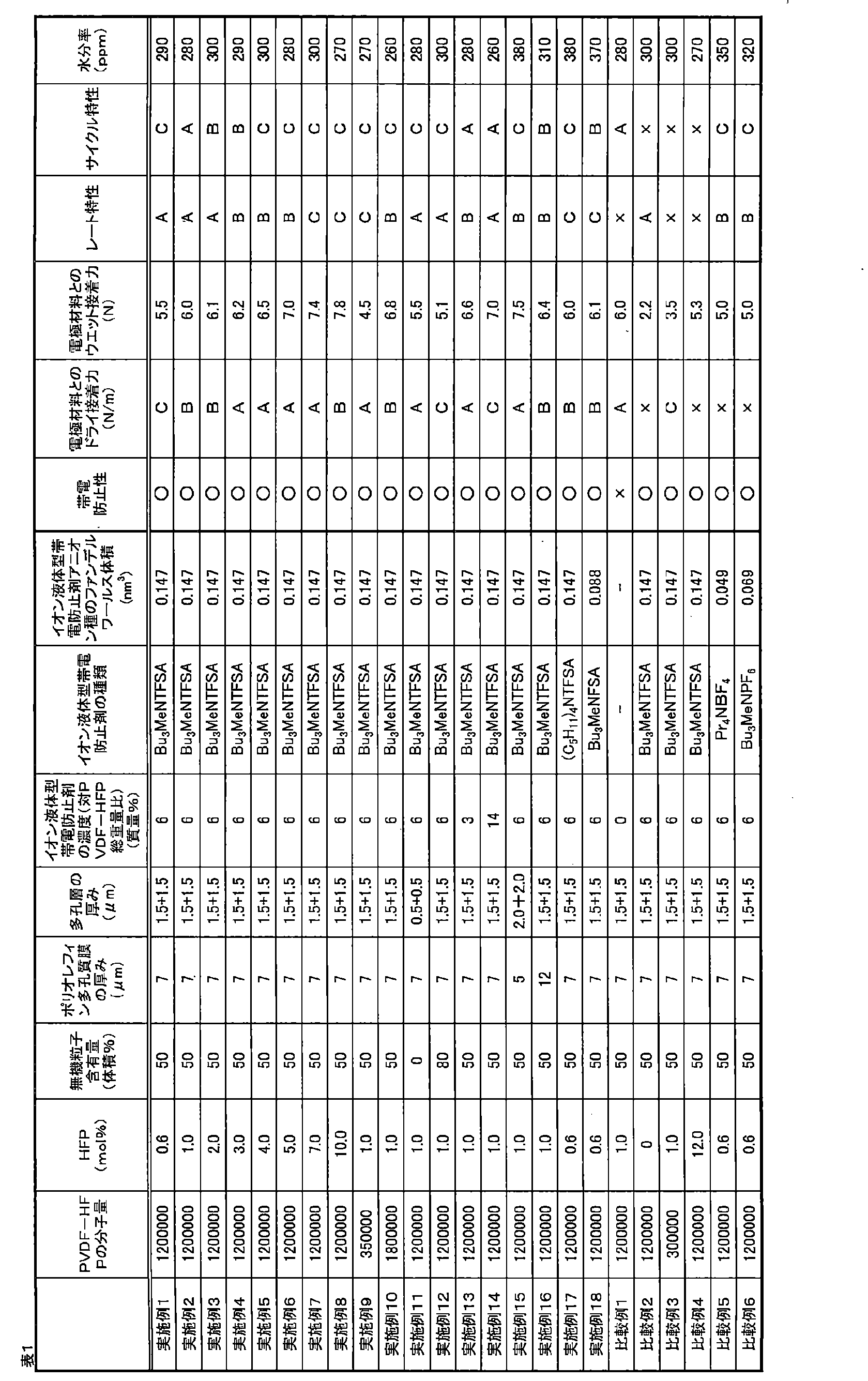
本発明の非水二次電池用セパレータは電極材料との接着性と帯電防止性に優れ、特に高速で電極と電池用セパレータを重ね合わせて電極体を製造する場合に好適に使用することができる。さらにフッ化ビニリデン-ヘキサフルオロプロピレン共重合体を含む多孔層に電解液に溶解する疎水性イオン液体型帯電防止剤を含有させることによって帯電防止性が得られることのみならず、電池組み立て工程のドライ圧着工程において多孔層の多孔構造変形(潰れ)を最小限に抑制することができ、結果として、電池組み立て後、優れたレート特性及びサイクル特性を保持できる。
本発明を詳細にまた特定の実施態様を参照して説明したが、本発明の精神と範囲を逸脱することなく様々な変更や修正を加えることができることは当業者にとって明らかである。
本出願は、2019年3月13日出願の日本特許出願(特願2019-046493)に基づくものであり、その内容はここに参照として取り込まれる。
本出願は、2019年3月13日出願の日本特許出願(特願2019-046493)に基づくものであり、その内容はここに参照として取り込まれる。
10…電池用セパレータ
11…負極(接着性評価用)
20…ラミネートフィルム
30…試験用巻回体
40…アルミニウム製L字アングル(下側)
41…アルミニウム製L字アングル(上側)
11…負極(接着性評価用)
20…ラミネートフィルム
30…試験用巻回体
40…アルミニウム製L字アングル(下側)
41…アルミニウム製L字アングル(上側)
Claims (7)
- ポリオレフィン多孔質膜と、前記ポリオレフィン多孔質膜の少なくとも一方の面に積層された多孔層とを備える非水二次電池用セパレータであって、前記多孔層はフッ化ビニリデン-ヘキサフルオロプロピレン共重合体と非水電解液に溶解する疎水性イオン液体型帯電防止剤を含み、前記フッ化ビニリデン-ヘキサフルオロプロピレン共重合体は0.3mol%以上10mol%以下のヘキサフルオロプロピレン単位を有し、重量平均分子量が35万以上200万以下であり、前記非水電解液に溶解する疎水性イオン液体型帯電防止剤は、カチオンとして炭素数がC4以上である炭化水素基を1つ以上有する四級アンモニウムイオンを含むフッ素系四級アンモニウム塩である非水二次電池用セパレータ。
- 前記フッ素系四級アンモニウム塩は、アニオンとしてファンデルワールス体積が0.08nm3以上であるフッ素含有アニオンを含む請求項1に記載の非水二次電池用セパレータ。
- 前記非水電解液に溶解する疎水性イオン液体型帯電防止剤を、前記フッ化ビニリデン-ヘキサフルオロプロピレン共重合体に対し0.3~30質量%含有する請求項1または2に記載の非水二次電池用セパレータ。
- 前記多孔層に無機粒子を含む請求項1から3のいずれか一項に記載の非水二次電池用セパレータ。
- 前記ポリオレフィン多孔質膜の厚さが16μm以下である請求項1から4のいずれか一項に記載の非水二次電池用セパレータ。
- 前記ポリオレフィン多孔質膜の厚さが7μm以下である請求項1から5のいずれか一項に記載の非水二次電池用セパレータ。
- 請求項1から6のいずれか一項に記載の非水二次電池用セパレータを用いたことを特徴とする非水二次電池。
Priority Applications (1)
| Application Number | Priority Date | Filing Date | Title |
|---|---|---|---|
| JP2020517396A JPWO2020184351A1 (ja) | 2019-03-13 | 2020-03-04 |
Applications Claiming Priority (2)
| Application Number | Priority Date | Filing Date | Title |
|---|---|---|---|
| JP2019-046493 | 2019-03-13 | ||
| JP2019046493 | 2019-03-13 |
Publications (1)
| Publication Number | Publication Date |
|---|---|
| WO2020184351A1 true WO2020184351A1 (ja) | 2020-09-17 |
Family
ID=72427917
Family Applications (1)
| Application Number | Title | Priority Date | Filing Date |
|---|---|---|---|
| PCT/JP2020/009271 Ceased WO2020184351A1 (ja) | 2019-03-13 | 2020-03-04 | 非水二次電池用セパレータ及び非水二次電池 |
Country Status (2)
| Country | Link |
|---|---|
| JP (1) | JPWO2020184351A1 (ja) |
| WO (1) | WO2020184351A1 (ja) |
Cited By (3)
| Publication number | Priority date | Publication date | Assignee | Title |
|---|---|---|---|---|
| WO2023053821A1 (ja) * | 2021-09-30 | 2023-04-06 | 東レ株式会社 | 多孔性フィルム、二次電池用セパレータおよび二次電池 |
| CN116487825A (zh) * | 2023-06-01 | 2023-07-25 | 湖州南木纳米科技有限公司 | 一种提升锂电池极化放电的隔膜及其制备方法 |
| CN116706423A (zh) * | 2023-04-23 | 2023-09-05 | 哈尔滨工业大学 | 一种用于液态碳酸酯基电解液锂金属电池的复合隔膜及其制备和应用 |
Citations (7)
| Publication number | Priority date | Publication date | Assignee | Title |
|---|---|---|---|---|
| JP2009259755A (ja) * | 2008-03-25 | 2009-11-05 | Hitachi Chem Co Ltd | 電気化学素子用セパレータ、及びこれを用いたリチウムイオン電池 |
| JP2010050076A (ja) * | 2008-07-03 | 2010-03-04 | Hitachi Chem Co Ltd | 電気化学素子用セパレータ、これを用いたリチウム電池又はリチウムイオン電池、及び電気化学素子用セパレータの製造方法 |
| JP2012510704A (ja) * | 2009-08-10 | 2012-05-10 | エルジー・ケム・リミテッド | リチウム二次電池 |
| JP2015079752A (ja) * | 2013-10-18 | 2015-04-23 | 三星エスディアイ株式会社Samsung SDI Co.,Ltd. | コーティング分離膜、及びそれを含む電気化学素子 |
| JP2017135111A (ja) * | 2015-03-24 | 2017-08-03 | 帝人株式会社 | 非水系二次電池用セパレータ及び非水系二次電池 |
| JP2018503956A (ja) * | 2015-01-28 | 2018-02-08 | バイエリシエ・モトーレンウエルケ・アクチエンゲゼルシヤフト | 複合セパレーターおよび複合セパレーターを含むリチウムイオン電池ならびに複合セパレーターの製造方法 |
| WO2019054422A1 (ja) * | 2017-09-15 | 2019-03-21 | 東レ株式会社 | 非水二次電池用セパレータおよび非水二次電池 |
-
2020
- 2020-03-04 WO PCT/JP2020/009271 patent/WO2020184351A1/ja not_active Ceased
- 2020-03-04 JP JP2020517396A patent/JPWO2020184351A1/ja active Pending
Patent Citations (7)
| Publication number | Priority date | Publication date | Assignee | Title |
|---|---|---|---|---|
| JP2009259755A (ja) * | 2008-03-25 | 2009-11-05 | Hitachi Chem Co Ltd | 電気化学素子用セパレータ、及びこれを用いたリチウムイオン電池 |
| JP2010050076A (ja) * | 2008-07-03 | 2010-03-04 | Hitachi Chem Co Ltd | 電気化学素子用セパレータ、これを用いたリチウム電池又はリチウムイオン電池、及び電気化学素子用セパレータの製造方法 |
| JP2012510704A (ja) * | 2009-08-10 | 2012-05-10 | エルジー・ケム・リミテッド | リチウム二次電池 |
| JP2015079752A (ja) * | 2013-10-18 | 2015-04-23 | 三星エスディアイ株式会社Samsung SDI Co.,Ltd. | コーティング分離膜、及びそれを含む電気化学素子 |
| JP2018503956A (ja) * | 2015-01-28 | 2018-02-08 | バイエリシエ・モトーレンウエルケ・アクチエンゲゼルシヤフト | 複合セパレーターおよび複合セパレーターを含むリチウムイオン電池ならびに複合セパレーターの製造方法 |
| JP2017135111A (ja) * | 2015-03-24 | 2017-08-03 | 帝人株式会社 | 非水系二次電池用セパレータ及び非水系二次電池 |
| WO2019054422A1 (ja) * | 2017-09-15 | 2019-03-21 | 東レ株式会社 | 非水二次電池用セパレータおよび非水二次電池 |
Cited By (3)
| Publication number | Priority date | Publication date | Assignee | Title |
|---|---|---|---|---|
| WO2023053821A1 (ja) * | 2021-09-30 | 2023-04-06 | 東レ株式会社 | 多孔性フィルム、二次電池用セパレータおよび二次電池 |
| CN116706423A (zh) * | 2023-04-23 | 2023-09-05 | 哈尔滨工业大学 | 一种用于液态碳酸酯基电解液锂金属电池的复合隔膜及其制备和应用 |
| CN116487825A (zh) * | 2023-06-01 | 2023-07-25 | 湖州南木纳米科技有限公司 | 一种提升锂电池极化放电的隔膜及其制备方法 |
Also Published As
| Publication number | Publication date |
|---|---|
| JPWO2020184351A1 (ja) | 2020-09-17 |
Similar Documents
| Publication | Publication Date | Title |
|---|---|---|
| KR102743149B1 (ko) | 비수계 이차전지용 세퍼레이터 및 비수계 이차전지 | |
| CN108352485B (zh) | 非水系二次电池用隔膜及非水系二次电池 | |
| JPWO2019054422A1 (ja) | 非水二次電池用セパレータおよび非水二次電池 | |
| KR102771571B1 (ko) | 비수계 이차전지용 세퍼레이터 및 비수계 이차전지 | |
| CN106030857B (zh) | 层叠多孔膜及非水电解液二次电池 | |
| JP5282180B1 (ja) | 非水系二次電池用セパレータ及び非水系二次電池 | |
| JP5282181B1 (ja) | 非水系二次電池用セパレータ及び非水系二次電池 | |
| US10199623B2 (en) | Separator for nonaqueous secondary battery, and nonaqueous secondary battery | |
| US10714723B2 (en) | Separator for a non-aqueous secondary battery, and non-aqueous secondary battery | |
| JP5356878B2 (ja) | 非水系二次電池用セパレータ | |
| JP6953629B2 (ja) | 電気化学素子用セパレータ、その製造方法、及びそれを含む電気化学素子 | |
| JP4705334B2 (ja) | 電子部品用セパレータ及びその製造方法 | |
| US9755208B2 (en) | Non-aqueous-secondary-battery separator and non-aqueous secondary battery | |
| US11777175B2 (en) | Separator for non-aqueous secondary battery, non-aqueous secondary battery, and method of manufacturing non-aqueous secondary battery | |
| JP5532430B2 (ja) | 複合多孔質膜、複合多孔質膜の製造方法並びにそれを用いた電池用セパレーター | |
| EP3920264B1 (en) | Non-aqueous secondary battery separator and non-aqueous secondary battery | |
| WO2020184351A1 (ja) | 非水二次電池用セパレータ及び非水二次電池 | |
| JP7545216B2 (ja) | 非水系二次電池用セパレータ及び非水系二次電池 | |
| EP3920318B1 (en) | Separator for non-aqueous secondary battery, and non-aqueous secondary battery | |
| JP5888079B2 (ja) | セパレータ、及びそれを用いた非水系二次電池 | |
| JP7413180B2 (ja) | 非水系二次電池 | |
| JP2023151013A (ja) | 非水系二次電池用セパレータ及び非水系二次電池 |
Legal Events
| Date | Code | Title | Description |
|---|---|---|---|
| ENP | Entry into the national phase |
Ref document number: 2020517396 Country of ref document: JP Kind code of ref document: A |
|
| 121 | Ep: the epo has been informed by wipo that ep was designated in this application |
Ref document number: 20769423 Country of ref document: EP Kind code of ref document: A1 |
|
| NENP | Non-entry into the national phase |
Ref country code: DE |
|
| 122 | Ep: pct application non-entry in european phase |
Ref document number: 20769423 Country of ref document: EP Kind code of ref document: A1 |