WO2020184172A1 - 車両制御装置、通信方法 - Google Patents
車両制御装置、通信方法 Download PDFInfo
- Publication number
- WO2020184172A1 WO2020184172A1 PCT/JP2020/007553 JP2020007553W WO2020184172A1 WO 2020184172 A1 WO2020184172 A1 WO 2020184172A1 JP 2020007553 W JP2020007553 W JP 2020007553W WO 2020184172 A1 WO2020184172 A1 WO 2020184172A1
- Authority
- WO
- WIPO (PCT)
- Prior art keywords
- signal
- control device
- vehicle control
- vehicle
- communication unit
- Prior art date
- Legal status (The legal status is an assumption and is not a legal conclusion. Google has not performed a legal analysis and makes no representation as to the accuracy of the status listed.)
- Ceased
Links
Images

Classifications
-
- B—PERFORMING OPERATIONS; TRANSPORTING
- B60—VEHICLES IN GENERAL
- B60R—VEHICLES, VEHICLE FITTINGS, OR VEHICLE PARTS, NOT OTHERWISE PROVIDED FOR
- B60R25/00—Fittings or systems for preventing or indicating unauthorised use or theft of vehicles
- B60R25/20—Means to switch the anti-theft system on or off
- B60R25/24—Means to switch the anti-theft system on or off using electronic identifiers containing a code not memorised by the user
-
- B—PERFORMING OPERATIONS; TRANSPORTING
- B60—VEHICLES IN GENERAL
- B60R—VEHICLES, VEHICLE FITTINGS, OR VEHICLE PARTS, NOT OTHERWISE PROVIDED FOR
- B60R25/00—Fittings or systems for preventing or indicating unauthorised use or theft of vehicles
- B60R25/40—Features of the power supply for the anti-theft system, e.g. anti-theft batteries, back-up power supply or means to save battery power
-
- E—FIXED CONSTRUCTIONS
- E05—LOCKS; KEYS; WINDOW OR DOOR FITTINGS; SAFES
- E05B—LOCKS; ACCESSORIES THEREFOR; HANDCUFFS
- E05B49/00—Electric permutation locks; Circuits therefor ; Mechanical aspects of electronic locks; Mechanical keys therefor
Definitions
- This disclosure relates to a vehicle control device and a communication method.
- Patent Document 1 discloses a smart key system (smart key system) using a beacon.
- the output radio field strength is determined according to the vehicle condition.
- the vehicle control device of the present disclosure aims to reduce power consumption.
- the vehicle control device of the present disclosure is a vehicle control device that communicates with a mobile terminal.
- the mobile terminal can receive a search signal for searching the mobile terminal and transmit a response signal in response to the search signal.
- the vehicle control device is mounted on the vehicle and controls the operation of the vehicle.
- the vehicle control device includes a communication unit, a distance determination unit, and a signal generation unit.
- the communication unit can transmit the search signal and receive the response signal.
- the distance determination unit acquires the first information indicating the first position where the vehicle control device exists and the second information indicating the second position where the mobile terminal exists, and the first information. The distance between the position and the second position is determined.
- the signal generation unit outputs a standby signal to the communication unit, and causes the communication unit to transmit the search signal after waiting for a time corresponding to the result of determination by the distance determination unit.
- the present disclosure can be realized not only as a vehicle control device having such a characteristic element, but also as a communication method in which such a characteristic process is a step, or as a program for causing a computer to execute such a step. Can be done. Further, it can be realized as a semiconductor integrated circuit that realizes a part or all of the vehicle control device, or can be realized as a communication system including the vehicle control device.
- the electric power consumed by the vehicle control device is reduced.
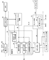
- FIG. 1 is a block diagram illustrating the configuration of the vehicle control device and the relationship between the vehicle control device and the communication target of the vehicle control device according to the embodiment.
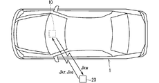
- FIG. 2 is a diagram illustrating a vehicle control device, a vehicle equipped with the vehicle control device, and communication between the mobile terminal and the vehicle control device.
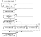
- FIG. 3 is a flowchart illustrating the operation of the vehicle control device 10.
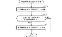
- FIG. 4 is a flowchart illustrating a process of setting the learning time.
- FIG. 5 is a flowchart illustrating a process of canceling the standby process.
- the vehicle control device of the present disclosure is a vehicle control device that communicates with a mobile terminal.
- the mobile terminal can receive a search signal for searching the mobile terminal and transmit a response signal in response to the search signal.
- the vehicle control device is mounted on the vehicle and controls the operation of the vehicle.
- the vehicle control device includes a communication unit, a distance determination unit, and a signal generation unit.
- the communication unit can transmit the search signal and receive the response signal.
- the distance determination unit acquires the first information indicating the first position where the vehicle control device exists and the second information indicating the second position where the mobile terminal exists, and the first information. The distance between the position and the second position is determined.
- the signal generation unit outputs a standby signal to the communication unit, and causes the communication unit to transmit the search signal after waiting for a time corresponding to the result of determination by the distance determination unit.
- the vehicle control device of the present disclosure is advantageous from the viewpoint of reducing the power consumption as compared with the case where the search signal is transmitted without waiting.
- the standby signal causes the communication unit to transmit the search signal after the first time elapses after the distance is determined to be less than the predetermined threshold value, and the distance is equal to or greater than the predetermined threshold value.
- the operation of the vehicle 1 is performed as compared with the case where it is determined that the distance between the two is less than the threshold distance. Less need to get started.
- the standby signal does not cause the communication unit to transmit the search signal when it is determined that the distance is equal to or greater than a predetermined threshold value. Not transmitting the search signal is further advantageous from the viewpoint of reducing the power consumed by the vehicle control device of the present disclosure.
- the vehicle control device further includes a standby time generation unit, and the standby time generation unit outputs the first time corresponding to the first position to the signal generation unit.
- the search signal is transmitted after waiting for a time suitable for that point.
- the communication unit does not transmit the search signal.
- the vehicle control device further includes a body ECU, an entry ECU, and a wireless ECU, the body ECU controls the operation of the vehicle, and the entry ECU sends a start signal to start the operation of the vehicle.
- the power consumed by the wireless ECU is smaller than the power consumed by the body ECU and the power consumed by the entry ECU.
- the mobile terminal can be searched from the vehicle control device of the present disclosure according to the schedule (Schedule) or the request from the mobile terminal.
- the communication method of the present disclosure is a communication method between a mobile terminal and a vehicle control device.
- the mobile terminal can receive a search signal for searching the mobile terminal and transmit a response signal in response to the search signal, and the vehicle control device is mounted on the vehicle to control the operation of the vehicle.
- the first information indicating the first position where the vehicle control device exists and the second information indicating the second position where the mobile terminal exists are acquired, and the first position and the second position are obtained.
- the search signal is transmitted after determining the distance between the two and waiting for a time corresponding to the result of the determination.
- FIG. 1 is a block diagram illustrating the configuration of the vehicle control device 10 and the relationship between the vehicle control device 10 and the communication target of the vehicle control device 10.
- FIG. 2 is a diagram illustrating communication between the vehicle control device 10, the vehicle 1 equipped with the vehicle control device 10, and the mobile terminal 20 and the vehicle control device 10.
- the vehicle control device 10 controls the operation of the vehicle 1 and communicates with the mobile terminal 20.
- the mobile terminal 20 can receive the search signal Jkw and transmit the response signal Jkr.
- the mobile terminal 20 also functions as an electronic key for starting the operation of the vehicle 1, and can transmit a start request signal Jke requesting the start of the operation. From this point of view, the mobile terminal 20 is referred to as an "electronic key" in FIG.
- a smartphone smarttphone
- the vehicle control device 10 includes a communication unit 161, a distance determination unit 112, and a signal generation unit 113.
- the communication unit 161 has a function of transmitting and receiving to and from the mobile terminal 20.
- the communication unit 161 can transmit the search signal Jkw and receive the response signal Jkr and the start request signal Jke.
- the distance determination unit 112 acquires the first information J0 from the car navigation device 12.
- the first information J0 indicates the first position where the vehicle control device 10 exists.
- the car navigation device 12 communicates with a data center (data center) 30 outside the vehicle control device 10 to acquire the first information J0.
- the first information J0 is obtained by the Global Positioning System (hereinafter referred to as "GPS") 40.
- FIG. 1 illustrates a case where the car navigation device 12 is included in the vehicle control device 10.
- the car navigation device 12 may not be included in the vehicle control device 10.
- the distance determination unit 112 acquires the second information Jg from the data center 30.
- the second information Jg indicates a second position where the mobile terminal 20 exists.
- the second information Jg is obtained by GPS40.
- the data center 30 communicates with the mobile terminal 20 and GPS 40, and obtains the second information Jg by the communication.
- the GPS data receiving circuit 111 receives GPS data (data) including the second information Jg from the data center 30, obtains the second information Jg from the GPS data, and sends the second information Jg to the distance determination unit 112. The case where it is transmitted is illustrated.
- the distance determination unit 112 determines the distance between the first position and the second position from the first information J0 and the second information Jg.
- the signal generation unit 113 generates the standby signal Js and outputs the standby signal Js to the communication unit 161.
- the standby signal Js is a signal that causes the communication unit 161 to transmit the search signal Jkw after waiting for a time corresponding to the result of the determination by the distance determination unit 112.
- the communication unit 161 waits for a time corresponding to the result of the determination by the distance determination unit 112, and then transmits the search signal Jkw.
- the communication unit 161 uses, for example, a communication method based on Bluetooth Low Energy (Bluetooth is a registered trademark) (hereinafter, "BLE") to communicate.
- BLE Bluetooth Low Energy
- the communication method is specified, for example, in the standard IEEE802.5.1.
- FIG. 1 a case where the communication unit 161 is modularized in the entry ECU 16 is exemplified, and is referred to as a “BLE module”.
- the entry ECU 16 is an ECU having a function of starting the operation of the vehicle 1.
- the ECU is an electronic control unit (Electronic Control Unit).
- the communication unit 161 adopts a communication method based on BLE, a so-called Advertise signal can be adopted as the search signal Jkw.
- transmitting the search signal Jkw can be expressed as advertising.
- the search signal Jkw may be a so-called wake-up signal.
- the wake-up signal functions as a signal for calling the mobile terminal 20 in the sleep state waiting for communication to perform communication.
- a signal in the LF (Low Frequency) band for example, 30 kHz to 300 kHz
- the communication unit 161 does not have to adopt the communication method based on BLE.
- the communication unit 161 transmits the search signal Jkw and receives the response signal Jkr from the mobile terminal 20, the communication unit 161 performs a process of mutually authenticating with the mobile terminal 20 by known communication. After the authentication is obtained, the mobile terminal 20 transmits the start request signal Jke to the communication unit 161. When the communication unit 161 receives the start request signal Jke, the entry ECU 16 outputs the start signal Je to the body ECU 13.
- the body ECU 13 is an ECU that controls the operation of the vehicle 1.
- the body ECU 13 is connected to the sensor group 14 and the actuator group 15.
- the sensor group 14 includes a sensor that detects that the occupant is seated.
- the actuator group 15 includes, for example, an actuator that performs ignition, an actuator that performs steering, and an actuator that locks and unlocks a door.
- the body ECU 13 receives the start signal Je and causes the actuator group 15 to unlock the door.
- the body ECU 13 that has received the start signal Je may further cause the actuator group 15 to ignite.
- the body ECU 13 receives information from the sensor group 14 and outputs a state signal Jc to the signal generation unit 113.
- the state signal Jc is a signal indicating the state of the vehicle 1.
- the status signal Jc includes, for example, information on whether or not the occupant is seated.
- the body ECU 13 and the entry ECU 16 are included in the vehicle control device 10 together with the wireless ECU 11.
- the GPS data receiving circuit 111, the distance determination unit 112, and the signal generation unit 113 are included in the wireless ECU 11.
- the function of the wireless ECU 11 is mainly to generate the standby signal Js, it is compared with the power consumed by the body ECU 13 that controls the operation of the vehicle 1 and the power consumed by the entry ECU 16 that starts the operation of the vehicle 1. Therefore, the power consumed by the wireless ECU 11 is small.
- FIG. 3 is a flowchart (flow chart) illustrating the operation of the vehicle control device 10.
- FIG. 3 illustrates a process of starting a wait until the search signal Jkw is transmitted.
- step S101 it is determined whether or not the user is getting off. If the result determined in step S101 is negative, that is, if it is determined that the user has not disembarked, step S101 is repeatedly executed.
- the communication unit 161 when it is determined that the user exists as a occupant in the vehicle 1, the communication unit 161 does not transmit the search signal Jkw. This is because it is assumed that the user carries the mobile terminal 20, and if the user exists in the vehicle 1 as an occupant, there is little need to start the operation of the vehicle 1 using the mobile terminal 20. Therefore, it is avoided that the search signal Jkw is unnecessarily transmitted, and this avoidance is advantageous from the viewpoint of reducing the electric power consumed by the communication unit 161 and thus the electric power consumed by the vehicle control device 10.
- Such a negative judgment is typically made when the user is seated.
- the sensor included in the sensor group 14 detects whether or not the user is seated, the state signal Jc including the detected content is transmitted from the body ECU 13 to the signal generation unit 113, and the signal generation unit 113 transmits the state signal.
- the determination in step S101 is made based on Jc.
- step S101 may be made using short-range wireless communication (Near Field Communication: NFC) between the mobile terminal 20 and the communication unit 161.
- NFC Near Field Communication
- step S102 is executed.
- the position information is acquired.
- the position information referred to in step S102 is information about the first position and the second position.
- Step S102 corresponds to an operation in which the distance determination unit 112 acquires the first information J0 and the second information Jg.
- Step S103 is executed after the process executed in step S102 is completed.
- a predetermined threshold value is between the vehicle 1 (more specifically, the vehicle control device 10 mounted on the vehicle 1) and the user (more specifically, the mobile terminal 20 carried by the user). It is determined whether or not the vehicle is separated by a distance smaller than the distance (hereinafter referred to as "threshold distance"). In FIG. 3, in step S103, the determination is abbreviated as "is the distance between the two parties small?".
- Step S103 corresponds to an operation in which the distance determination unit 112 determines the distance between the first position and the second position from the first information J0 and the second information Jg.
- step S104 it is determined whether or not the first position is a position registered in the vehicle control device 10.
- step S104 If a positive determination is obtained in step S104, that is, if it is determined that the position of the vehicle control device 10 has already been registered in the vehicle control device 10, steps S105 and S108 are executed.
- step S105 it waits for step S108 to be executed at the time learned (hereinafter, abbreviated as "learning time” in the drawings) as described later.
- learning time the time learned
- step S104 If a negative determination is made in step S104, that is, if it is determined that the position of the vehicle control device 10 has not yet been registered in the vehicle control device 10, steps S106 and S108 are executed. In step S106, execution of step S108 is awaited at a predetermined time.
- step S105 the learning time referred to in step S105 and the predetermined time referred to in step S106 are collectively referred to as the first time.
- step S107 the execution of step S108 is awaited in the second time, which is longer than the first time.
- the second time may be regarded as a very large time, and step S101 or step S102 may be executed again instead of substantially executing steps S107 and S108.
- Such an alternative flow is shown by the dashed line in FIG.
- Step S108 corresponds to the communication unit 161 transmitting the search signal Jkw. Therefore, all of steps S105, S106, and S107 are common in that they are processes that wait for the search signal Jkw to be transmitted. From this point of view, steps S105, S106, and S107 can be collectively regarded as standby processing.
- the standby process is shown as step S110 in FIG.
- the distance determination unit 112 determines (corresponding to step S103 in FIG. 3) before the signal generation unit 113 generates the standby signal Js and the standby signal Js transmits the search signal Jkw to the communication unit 161.
- the standby signal Js includes information indicating the first time or the second time.
- the communication unit 161 obtains information indicating the first time or the second time from the standby signal Js.
- the standby signal Js causes the communication unit 161 to wait for a time corresponding to the result of the determination by the distance determination unit 112 (see step S103) (see step S110), and then transmits the search signal Jkw to the communication unit 161 (see step S108). ).
- the communication unit 161 transmits the search signal Jkw without waiting
- causing the communication unit 161 to transmit the search signal Jkw after waiting causes the power consumed by the communication unit 161 and thus the vehicle control device 10. It is advantageous from the viewpoint of reducing the power consumed by.
- the standby signal Js does not cause the communication unit 161 to transmit the search signal Jkw when it is determined that the distance between the two parties is equal to or greater than a predetermined threshold value. You can also. Not transmitting the search signal Jkw is further advantageous from the viewpoint of reducing the power consumed by the communication unit 161 and, by extension, the power consumed by the vehicle control device 10.
- the wireless ECU 11 further includes a standby time generation unit 114.
- the standby time generation unit 114 gives the learning time referred to in step S105 to the signal generation unit 113, and the signal generation unit 113 generates the standby signal Js that realizes the processing in step S105.
- the signal generation unit 113 generates the standby signal Js with the learning time as the first time.
- the standby time generation unit 114 acquires the first information J0 from the car navigation device 12.
- the standby time generation unit 114 stores the registered value for the first position.
- the standby time generation unit 114 determines whether or not the first position obtained from the first information J0 corresponds to the registered value, and if so, outputs the learning time to the signal generation unit 113 corresponding to the registered value. To do.
- the parking lot occupied by the user can be mentioned as the registered value.
- the vehicle 1 When the vehicle 1 is parked in the parking lot, it is assumed that it is not necessary to frequently transmit the search signal Jkw.
- the learning time can be set longer.
- the registered value a parking lot owned by a store frequently used by the user can be mentioned.
- the average value of the time when the user uses the store is learned.
- the waiting time generation unit 114 outputs the average value as the learning time corresponding to the registered value.
- FIG. 4 is a flowchart illustrating the process of setting the learning time. The flowchart is executed, for example, by the waiting time generation unit 114.
- step S301 the time from when the vehicle 1 is parked until the vehicle is driven again (hereinafter, "parking time” in the figure) is acquired in association with the relevant point.
- the point can be acquired from the car navigation device 12 as the first information J0.
- the parking time can be obtained from, for example, a timekeeping device (not shown) normally provided by the ECU for the wireless ECU 11 to perform its operation.
- Step S302 is executed after the process in step S301 is completed.
- step S302 it is determined whether or not the data used for learning has been sufficiently accumulated. The judgment depends on what kind of learning is performed. If a negative result is obtained in the judgment, the learning time is not set and the flowchart ends. If a positive result is obtained in the determination, step S303 is executed, and the learning time is set in association with the relevant point.
- the communication unit 161 has a time suitable for that point. After waiting at, the search signal Jkw is transmitted.
- step S110 When the standby process is being executed in step S110, a request to cancel the standby process by the interrupt process is assumed. For example, as the first case, when step S105 is being executed, a case where the user reaches the vehicle 1 and generates a signal for releasing the door is exemplified in a time shorter than the learning time.
- the touch sensor (touch sensor) 17 outputs a start request signal Jcw to the entry ECU 16, more specifically, to the communication unit 161 when the user touches the door handle.
- the start request signal Jcw is a signal requesting that the operation of the vehicle 1 be started.
- the touch sensor 17 can be included in the sensor group 14.
- step S105 Even if the communication unit 161 executes step S105 according to the standby signal Js, the start request signal Jcw is given, and the start request signal Jcw is used as an trigger for interrupt processing to interrupt step S105. Then, the communication unit 161 executes step S108.
- step S105 As the second case, a case where the standby process is canceled due to the occurrence of a predetermined event while step S105 is being executed is exemplified.
- the signal Ja includes information indicating the occurrence of a predetermined event.
- the signal generation unit 113 generates and outputs a signal Ji by receiving the signal Ja.
- the signal Ji is a command for causing the communication unit 161 to release the standby process executed in step S110.
- Step S105 is interrupted with this signal Ji as an trigger for interrupt processing. Then, the communication unit 161 executes step S108.
- the signal Ja may be transmitted from the mobile terminal 20.
- FIG. 1 the state in which the signal Ja is transmitted from the mobile terminal 20 is schematically shown by a broken line.
- FIG. 5 is a flowchart illustrating a process of canceling the standby process.
- step S201 it is determined whether or not the standby process is being executed. The determination can be made by the communication unit 161 or the entry ECU 16 including the communication unit 161. If the determination in step S201 is negative, that is, if the standby process is not executed, the communication unit 161 executes step S108.
- step S202 it is determined whether or not there is an opportunity to cancel the standby process.
- the trigger is the start request signal Jcw if it corresponds to the first case, and the signal Ji if it corresponds to the second case.
- the mobile terminal 20 can be searched from the vehicle control device 10 according to the schedule or the request from the mobile terminal 20.
- the following cases can be assumed for the event corresponding to the signal Ja: (i) When the vehicle 1 used by the user is parked near the home and equipped with a wireless device for transmitting a signal Ja by unlocking the home door, the home door is unlocked. Event; (ii) An event in which the clock, which is one of the functions of the mobile terminal 20 itself, detects that the current time has passed a predetermined time; (iii) An event in which the mobile terminal 20 has a function of detecting vibration, and it is detected that the mobile terminal 20 is gripped by the function.
- the above-described embodiment can be recognized as a communication method between the mobile terminal 20 and the vehicle control device 10.
- the mobile terminal 20 can receive the search signal Jkw for searching the mobile terminal 20 and transmit the response signal Jkr in response to the search signal Jkw.
- the vehicle control device 10 is mounted on the vehicle 1 and controls the operation of the vehicle 1.
- the communication method is: The first information J0 indicating the first position where the vehicle control device 10 exists and the second information Jg indicating the second position where the mobile terminal 20 exists are acquired; Determine the distance between the first and second positions; The search signal Jkw is transmitted after waiting for a time according to the result of the above determination.
- the vehicle control device 10 includes a computer composed of a microprocessor (microprocessor), a ROM (Read Only Memory), a RAM (Random Access Memory), and the like.
- An arithmetic processing unit such as a microprocessor reads a computer program (computer program) including a part or all of each step of the flowcharts shown in FIGS. 3 to 5 from a storage unit such as a ROM or RAM and executes the program.
- the computer programs of these plurality of devices can be installed from an external server device or the like, respectively.
- the computer programs of these plurality of devices are stored in recording media such as a CD-ROM (Compact Disc Read Only Memory), a DVD-ROM (Digital entirely Disk Read Only Memory), and a semiconductor memory (memory), respectively. It is distributed in.
- recording media such as a CD-ROM (Compact Disc Read Only Memory), a DVD-ROM (Digital entirely Disk Read Only Memory), and a semiconductor memory (memory), respectively. It is distributed in.
- the search signal Jkw may be transmitted as a group a plurality of times at a predetermined cycle, for example, at intervals of about several ms.
- the interval may change depending on the distance between the first position and the second position. For example, the closer the distance is, the shorter the interval may be.
- Vehicle 10 Vehicle control device 11 Wireless ECU 12 Car navigation device 13 Body ECU 14 Sensor group 15 Actuator group 16 Entry ECU 17 Touch sensor 20 Mobile terminal 30 Data center 40 GPS 111 GPS data reception circuit 112 Distance judgment unit 113 Signal generation unit 114 Standby time generation unit 161 Communication unit J0 1st information Ja, Ji signal Jc Status signal Jcw Start request signal Je Start signal Jg 2nd information Jke Start request signal Jkr Response signal Jkw search signal Js standby signal S101, S102, S103, S104, S105, S106, S107, S108, S110, S201, S202, S301, S302, S303 Step
Landscapes
- Engineering & Computer Science (AREA)
- Mechanical Engineering (AREA)
- Lock And Its Accessories (AREA)
Abstract
車両制御装置の消費する電力が低減される。携帯端末は、携帯端末を探索する探索信号を受信し、探索信号に応答する応答信号を送信可能である。車両制御装置は、通信部と、距離判断部と、信号生成部とを備える。通信部は探索信号を送信し、応答信号を受信可能である。距離判断部は、車両制御装置が存在する位置である第1位置を示す第1情報と携帯端末が存在する位置である第2位置を示す第2情報とを取得し、第1位置と第2位置との間の距離を判断する。信号生成部は、距離判断部による判断の結果に応じた時間で待機した後に探索信号を通信部に送信させる待機信号を生成する。
Description
本開示は、車両制御装置、通信方法に関する。
特許文献1にはビーコン(beacon)を用いたスマートキーシステム(smart key system)が開示される。当該技術では、車両状態に応じた出力電波強度が決定される。
しかし車両のユーザ(user)が当該車両から遠く離れている状況では、当該ユーザが当該車両に乗車するための処理、例えば当該車両のドア(door)の解錠を行う必要性は低い。よって当該状況において車両とスマートキー(smart key)との間の通信を行い続けることは消費電力の観点で望ましくない。
そこで、本開示の車両制御装置は、消費電力を低減することを目的とする。
本開示の車両制御装置は、携帯端末との間で通信する車両制御装置である。前記携帯端末は、前記携帯端末を探索する探索信号を受信し、前記探索信号に応答する応答信号を送信可能である。前記車両制御装置は車両に搭載され、前記車両の動作を制御する。前記車両制御装置は、通信部と、距離判断部と、信号生成部とを備える。前記通信部は前記探索信号を送信し、前記応答信号を受信可能である。前記距離判断部は、前記車両制御装置が存在する位置である第1位置を示す第1情報と前記携帯端末が存在する位置である第2位置を示す第2情報とを取得し、前記第1位置と前記第2位置との間の距離を判断する。前記信号生成部は待機信号を前記通信部へ出力し、前記待機信号は前記通信部に、前記距離判断部による判断の結果に応じた時間で待機した後に前記探索信号を送信させる。
本開示は、このような特徴的な要素を備える車両制御装置として実現できるだけでなく、かかる特徴的な処理をステップとする通信方法として実現したり、かかるステップをコンピュータに実行させるためのプログラムとして実現したりすることができる。また、車両制御装置の一部または全部を実現する半導体集積回路として実現したり、車両制御装置を含む通信システムとして実現したりすることができる。
本開示によれば、車両制御装置が消費する電力が低減される。
[本開示の実施形態の説明]
最初に本開示の実施態様が列記して説明される。本開示の車両制御装置は、次の通りである。
最初に本開示の実施態様が列記して説明される。本開示の車両制御装置は、次の通りである。
(1)本開示の車両制御装置は携帯端末との間で通信する車両制御装置である。前記携帯端末は、前記携帯端末を探索する探索信号を受信し、前記探索信号に応答する応答信号を送信可能である。前記車両制御装置は車両に搭載され、前記車両の動作を制御する。前記車両制御装置は、通信部と、距離判断部と、信号生成部とを備える。前記通信部は前記探索信号を送信し、前記応答信号を受信可能である。前記距離判断部は、前記車両制御装置が存在する位置である第1位置を示す第1情報と前記携帯端末が存在する位置である第2位置を示す第2情報とを取得し、前記第1位置と前記第2位置との間の距離を判断する。前記信号生成部は待機信号を前記通信部へ出力し、前記待機信号は前記通信部に、前記距離判断部による判断の結果に応じた時間で待機した後に前記探索信号を送信させる。
待機せずに探索信号を送信させる場合と比較して、消費する電力を低減する観点で本開示の車両制御装置が有利である。
(2)前記待機信号は、前記距離が所定の閾値未満であると判断された後、第1時間が経過した後に前記探索信号を前記通信部に送信させ、前記距離が所定の閾値以上であると判断されたとき、前記第1時間よりも長い第2時間が経過した後に前記探索信号を前記通信部に送信させることが好ましい。
車両と携帯端末との間の距離が閾値距離以上であると判断された場合には、二者間の距離が閾値距離未満であると判断された場合と比較して、当該車両1の動作を開始させる必要性が低い。第2時間を第1時間よりも長くすることにより、探索信号を不要に発信することが回避され、本開示の車両制御装置が消費する電力を低減する観点で有利である。
(3)前記待機信号は、前記距離が所定の閾値以上であると判断されたとき、前記通信部に、前記探索信号を送信させないことが好ましい。前記探索信号を送信しないことは、本開示の車両制御装置が消費する電力を低減する観点で、更に有利である。
(4)前記車両制御装置は待機時間生成部を更に備え、前記待機時間生成部は、前記第1位置に応じた前記第1時間を前記信号生成部に出力することが望ましい。
車両が特定の地点に駐車された場合には、その地点に適した時間で待機してから探索信号が送信される観点で有利である。
(5)前記車両において乗員が存在すると判断されたときには、前記通信部は前記探索信号を送信しないことが望ましい。
携帯端末を携帯していると想定される乗員が車両に存在していれば、携帯端末を用いて車両の動作を開始させる必要性が低い。よって探索信号を不要に発信することが回避され、本開示の車両制御装置が消費する電力を低減する観点で有利である。
(6)前記車両制御装置は、ボディECUと、エントリECUと、無線ECUとを更に備え、前記ボディECUは前記車両の動作を制御し、前記エントリECUは前記車両の動作を開始させる開始信号を前記ボディECUへ出力し、前記通信部は前記エントリECUに含まれ、前記距離判断部と前記信号生成部とは前記無線ECUに含まれ、前記無線ECUは、前記ボディECUおよび前記エントリECUのいずれとも別個に構成されることが望ましい。
無線ECUの機能は主として待機信号を生成することであるので、ボディECUで消費される電力、およびエントリECUで消費される電力と比較して、無線ECUで消費される電力は小さい。
(7)前記通信部は、前記探索信号を送信するまでに待機していても、割り込みの契機を受けた場合には、前記探索信号を送信することが望ましい。
このような割り込み処理により、スケジュール(Schedule)に応じて、あるいは携帯端末からの要求に応じて、本開示の車両制御装置から携帯端末を探索することができる。
(8)また、本開示の通信方法は、携帯端末と車両制御装置との間の通信方法である。前記携帯端末は、前記携帯端末を探索する探索信号を受信し、前記探索信号に応答する応答信号を送信可能であり、前記車両制御装置は車両に搭載され、前記車両の動作を制御し、前記車両制御装置が存在する位置である第1位置を示す第1情報と前記携帯端末が存在する位置である第2位置を示す第2情報とを取得し、前記第1位置と前記第2位置との間の距離を判断し、前記判断の結果に応じた時間で待機した後に前記探索信号を送信する。
このように待機して探索信号を送信することにより、待機せずに探索信号を送信させる場合と比較して、車両制御装置が消費する電力を低減する観点で有利である。
[本開示の実施形態の詳細]
本開示の車両制御装置の具体例が、以下に図面が参照されつつ説明される。なお、本開示はこれらの例示に限定されるものではなく、請求の範囲によって示され、請求の範囲と均等の意味および範囲内でのすべての変更が含まれることが意図される。以下に記載する実施形態の少なくとも一部が任意に組み合わせられてもよい。
本開示の車両制御装置の具体例が、以下に図面が参照されつつ説明される。なお、本開示はこれらの例示に限定されるものではなく、請求の範囲によって示され、請求の範囲と均等の意味および範囲内でのすべての変更が含まれることが意図される。以下に記載する実施形態の少なくとも一部が任意に組み合わせられてもよい。
[車両制御装置の構成例]
以下、実施形態1にかかる車両制御装置の構成例について説明される。図1は、車両制御装置10の構成および車両制御装置10と車両制御装置10の通信対象との関係を例示するブロック(block)図である。図2は車両制御装置10、車両制御装置10を搭載する車両1、および携帯端末20と車両制御装置10との通信を例示する図である。
以下、実施形態1にかかる車両制御装置の構成例について説明される。図1は、車両制御装置10の構成および車両制御装置10と車両制御装置10の通信対象との関係を例示するブロック(block)図である。図2は車両制御装置10、車両制御装置10を搭載する車両1、および携帯端末20と車両制御装置10との通信を例示する図である。
車両制御装置10は、車両1の動作を制御し、携帯端末20との間で通信する。携帯端末20は、探索信号Jkwを受信し、応答信号Jkrを送信可能である。また携帯端末20は車両1の動作を開始させる電子キーとしても機能し、当該動作が開始することを要求する開始要求信号Jkeを送信可能である。かかる観点で図1において携帯端末20には「電子キー」と表記される。このような機能を有する携帯端末20として、スマートフォン(smartphone)を挙げることができる。
車両制御装置10は、通信部161と、距離判断部112と、信号生成部113とを含む。通信部161は、携帯端末20との間で送受信する機能を有する。通信部161は探索信号Jkwを送信し、応答信号Jkr、開始要求信号Jkeを受信可能である。
距離判断部112は、第1情報J0をカーナビゲーション(Car navigation)装置12から取得する。第1情報J0は車両制御装置10が存在する位置である第1位置を示す。カーナビゲーション装置12は車両制御装置10の外部にあるデータセンタ(data center)30と通信し、第1情報J0を取得する。例えば、第1情報J0は全地球測位システム(Global Positioning System:以下「GPS」と称す)40によって得られる。図1ではカーナビゲーション装置12が車両制御装置10に含まれる場合が例示される。カーナビゲーション装置12が車両制御装置10に含まれなくてもよい。
距離判断部112は、第2情報Jgをデータセンタ30から取得する。第2情報Jgは、携帯端末20が存在する位置である第2位置を示す。例えば、第2情報JgはGPS40によって得られる。データセンタ30は携帯端末20およびGPS40と通信し、当該通信によって第2情報Jgを得る。図1ではGPSデータ受信回路111がデータセンタ30から第2情報Jgを含むGPSデータ(data)を受信し、当該GPSデータから第2情報Jgを得て、距離判断部112に第2情報Jgが伝達される場合が例示される。
距離判断部112は、第1情報J0と第2情報Jgとから、第1位置と第2位置との間の距離を判断する。
信号生成部113は待機信号Jsを生成し、待機信号Jsを通信部161へ出力する。待機信号Jsは通信部161に、距離判断部112による判断の結果に応じた時間で待機した後に探索信号Jkwを送信させる信号である。通信部161は、待機信号Jsを受信すると、距離判断部112による判断の結果に応じた時間で待機した後に、探索信号Jkwを送信する。
通信部161は、例えばBluetooth Low Energy(Bluetoothは登録商標)(以下「BLE」)に則った通信方式を採用して通信する。当該通信方式は例えば規格IEEE802.15.1で規定される。図1では通信部161はエントリ(entry)ECU16の中でモジュール(module)化されている場合が例示され、「BLEモジュール」と表記される。
エントリECU16は車両1の動作を開始させる機能を有するECUである。ここでECUとはエレクトロニック・コントロール・ユニット(Electronic Control Unit)である。
通信部161がBLEに則った通信方式を採用する場合、探索信号Jkwにはいわゆるアドバタイズ(Advertise)信号を採用できる。この場合、探索信号Jkwを送信することはアドバタイジング(Advertising)と表現できる。
探索信号Jkwは、いわゆるウェイクアップ(wake-up)信号であってもよい。ウェイクアップ信号は、通信を待機しているスリープ(sleep)状態にある携帯端末20に対して、通信を行えるように呼びかける信号として機能する。ウェイクアップ信号はLF(Low Frequency)帯(例えば30kHz~300kHz)の信号を用いることができる。この場合、通信部161はBLEに則った通信方式を採用しなくてもよい。
通信部161が探索信号Jkwを送信し、携帯端末20から応答信号Jkrを受信した場合、通信部161は携帯端末20との間で公知の通信によって相互を認証する処理が行われる。当該認証が得られた後、携帯端末20は開始要求信号Jkeを通信部161へ送信する。エントリECU16は、通信部161が開始要求信号Jkeを受信すると、開始信号Jeをボディ(body)ECU13へ出力する。
ボディECU13は車両1の動作を制御するECUである。ボディECU13はセンサ群14およびアクチュエータ(actuator)群15と接続される。センサ群14には乗員が着座していることを検知するセンサが含まれる。アクチュエータ群15には例えばイグニッション(ignition)を行わせるアクチュエータ、ステアリング(steering)を行わせるアクチュエータ、およびドアを施錠したり解錠したりするアクチュエータが含まれる。
ボディECU13は開始信号Jeを受けて、アクチュエータ群15にドアを解錠させる。開始信号Jeを受けたボディECU13は更に、アクチュエータ群15にイグニッションを行わせてもよい。
ボディECU13はセンサ群14からの情報を受け、状態信号Jcを信号生成部113に出力する。状態信号Jcは、車両1がどのような状態にあるかを示す信号である。状態信号Jcは例えば乗員が着座しているか否かの情報を含む。
ボディECU13およびエントリECU16は、無線ECU11と共に車両制御装置10に含まれる。GPSデータ受信回路111、距離判断部112および信号生成部113は無線ECU11に含まれる。
無線ECU11の機能は主として待機信号Jsを生成することであるので、車両1の動作を制御するボディECU13で消費される電力、および車両1の動作を開始させるエントリECU16で消費される電力と比較して、無線ECU11で消費される電力は小さい。
[車両制御装置の動作例]
図3は車両制御装置10の動作を例示するフローチャート(flow chart)である。図3では探索信号Jkwが送信されるまでの待機を開始する処理を例示する。
図3は車両制御装置10の動作を例示するフローチャート(flow chart)である。図3では探索信号Jkwが送信されるまでの待機を開始する処理を例示する。
ステップS101において、ユーザが降車しているか否かが判断される。ステップS101で判断された結果が否定的であれば、つまりユーザが降車していないと判断された場合には、ステップS101が繰り返し実行される。
換言すればユーザが車両1に乗員として存在していると判断された場合には、通信部161は探索信号Jkwを送信しない。当該ユーザは携帯端末20を携帯していると想定され、当該ユーザが乗員として車両1に存在していれば、携帯端末20を用いて車両1の動作を開始させる必要性が低いからである。よって探索信号Jkwを不要に発信することが回避され、この回避は通信部161が消費する電力を、ひいては車両制御装置10が消費する電力を低減する観点で有利である。
このような否定的な判断は、典型的には、ユーザが着座している場合になされる。例えば、センサ群14に含まれるセンサによってユーザが着座しているか否かが検知され、検知された内容を含む状態信号JcがボディECU13から信号生成部113へ伝達され、信号生成部113が状態信号Jcに基づいてステップS101における判断を行う。
あるいは携帯端末20と通信部161との間の近距離無線通信(Near Field Communication:NFC)を用いて、ステップS101における判断が行われてもよい。
ステップS101で判断された結果が肯定的であれば、つまりユーザが降車していると判断された場合には、ステップS102が実行される。ステップS102では位置情報が取得される。ステップS102においていう位置情報は、第1位置および第2位置についての情報である。ステップS102は距離判断部112が第1情報J0および第2情報Jgを取得する動作に相当する。
ステップS102において実行される処理が完了した後にステップS103が実行される。ステップS103では車両1(より具体的には当該車両1が搭載する車両制御装置10)とユーザ(より具体的には当該ユーザが携帯する携帯端末20)という二者の間が所定の閾値である距離(以下「閾値距離」と仮称)よりも小さい距離で離れているか否かが判断される。図3ではステップS103において、当該判断が「二者間距離は小?」と略記される。ステップS103は距離判断部112が第1情報J0および第2情報Jgから第1位置と第2位置との間の距離を判断する動作に相当する。
ステップS103において肯定的な判断が得られた場合、つまり二者間の距離が閾値距離未満であると判断された場合には、ステップS104が実行される。ステップS104では第1位置が車両制御装置10において登録済みである位置か否かが判断される。
ステップS104において肯定的な判断が得られた場合、つまり車両制御装置10の位置が既に車両制御装置10において登録されていると判断された場合には、ステップS105,S108が実行される。ステップS105では、後述されるように学習された時間(以下および図面で「学習時間」と略記)でステップS108が実行されることが待機される。ステップS105における待機が終了すると、ステップS108において探索信号Jkwを送信する処理(図において「アドバタイジング」として例示)が実行される。
ステップS104において否定的な判断がなされた場合、つまり車両制御装置10の位置が未だ車両制御装置10において登録されていないと判断された場合には、ステップS106,S108が実行される。ステップS106では、ステップS108が実行されることが、所定時間で待機される。
便宜上、ステップS105にいう学習時間と、ステップS106にいう所定時間とが第1時間と総称される。
ステップS103において否定的な判断が得られた場合、つまり二者間の距離が閾値距離以上であると判断された場合には、ステップS107,S108が実行される。ステップS107では第1時間よりも長い第2時間で、ステップS108を実行することが待機される。第2時間を非常に大きな時間として捉え、実質的にステップS107,S108を実行することに代えて、ステップS101またはステップS102が再び実行されてもよい。このような代替的な流れは図3において破線で示される。
ステップS108は通信部161が探索信号Jkwを送信することに対応する。よってステップS105,S106,S107のいずれも、探索信号Jkwを送信することを待機する処理である点において共通する。かかる観点から、ステップS105,S106,S107を纏めて待機処理と見ることができる。当該待機処理は図3においてステップS110として示される。かかる待機処理は、信号生成部113が待機信号Jsを生成し、待機信号Jsが通信部161に、探索信号Jkwを送信する前に、距離判断部112による判断(図3ではステップS103に相当)の結果に応じた時間、上述の例では第1時間または第2時間で待機させることに相当する。待機信号Jsは、第1時間または第2時間を示す情報を含む。通信部161は、待機信号Jsから第1時間または第2時間を示す情報を得る。
待機信号Jsは通信部161に、距離判断部112による判断(ステップS103参照)の結果に応じた時間で待機させた後に(ステップS110参照)探索信号Jkwを通信部161に送信させる(ステップS108参照)。通信部161に待機せずに探索信号Jkwを送信させる場合と比較して、通信部161に待機した後に探索信号Jkwを送信させることは、通信部161が消費する電力を、ひいては車両制御装置10が消費する電力を低減する観点で有利である。
二者間の距離が閾値距離以上であると判断された場合には、二者間の距離が閾値距離未満であると判断された場合と比較して、当該車両1の動作を開始させる必要性が低い。よって第2時間を第1時間よりも長くすることにより、探索信号Jkwを不要に発信することが回避される。この回避は通信部161が消費する電力を、ひいては車両制御装置10が消費する電力を低減する観点で有利である。
特に第2時間を非常に大きな時間として捉えれば、待機信号Jsは、二者間の距離が所定の閾値以上であると判断されたとき、通信部161に探索信号Jkwを送信させない、と見ることもできる。探索信号Jkwを送信しないことは、通信部161が消費する電力を、ひいては車両制御装置10が消費する電力を低減する観点で、更に有利である。
ステップS104,S105について更に説明が行われる。図1を参照して車両制御装置10は、より具体的には無線ECU11は、待機時間生成部114を更に含む。待機時間生成部114はステップS105にいう学習時間を信号生成部113に与え、ステップS105における処理を実現する待機信号Jsを信号生成部113が生成することに供する。信号生成部113は学習時間を第1時間として待機信号Jsを生成する。
待機時間生成部114は第1情報J0をカーナビゲーション装置12から取得する。待機時間生成部114は第1位置についての登録値を記憶する。待機時間生成部114は第1情報J0から得られた第1位置が当該登録値に該当するか否かを判断し、該当すれば当該登録値に対応して学習時間を信号生成部113に出力する。
例えば当該登録値としてユーザが占有する駐車場を挙げることができる。当該駐車場に車両1が駐車されている場合、頻回に探索信号Jkwを送信する必要がない場合が想定される。例えばユーザが車両1を使用しないと学習された時間帯では、学習時間を長く設定することができる。
あるいは例えば当該登録値としてユーザが頻回に利用する店舗が有する駐車場を挙げることができる。当該駐車場に車両1が駐車されている場合、ユーザが当該店舗を利用する時間の平均値が学習される。当該平均値を、当該登録値に対応する学習時間として待機時間生成部114が出力する。
このような登録値に対応して時間を学習することや、学習時間を記憶することは、周知の技術によって容易に実現されるので、ここではその詳細な説明を省略して簡単な説明を行う。
図4は学習時間を設定する処理を例示するフローチャートである。当該フローチャートは例えば待機時間生成部114によって実行される。
ステップS301において、車両1が駐車した後に再び当該車両が駆動されるまでの時間(以下および図において「駐車時間」)が当該地点と関連づけて取得される。当該地点は第1情報J0としてカーナビゲーション装置12から取得できる。駐車時間は、ECUが、例えば無線ECU11がその動作を行うために通常備える計時装置(不図示)から取得できる。
ステップS301における処理が完了してからステップS302が実行される。ステップS302では学習に用いるデータは十分蓄積されたか否かが判断される。当該判断はどのような学習が行われるかによって異なる。当該判断において否定的な結果が得られた場合には学習時間は設定されず、当該フローチャートは終了する。当該判断において肯定な結果が得られた場合にはステップS303が実行され、学習時間を当該地点と関連づけて設定する。
このように、第1位置に応じた第1時間が信号生成部113に出力されることにより、車両1が特定の地点に駐車された場合には、通信部161は、その地点に適した時間で待機した後に探索信号Jkwを送信する。
[待機に対する割り込み]
ステップS110において待機処理が実行されているとき、割り込み処理によって待機処理を解除させる要求が想定される。例えばその第1の場合として、ステップS105が実行されているときに、学習時間よりも短い時間でユーザが車両1に到達してドアを解除するための信号を発生させる場合が例示される。
ステップS110において待機処理が実行されているとき、割り込み処理によって待機処理を解除させる要求が想定される。例えばその第1の場合として、ステップS105が実行されているときに、学習時間よりも短い時間でユーザが車両1に到達してドアを解除するための信号を発生させる場合が例示される。
図1において、タッチセンサ(touch sensor)17はドアハンドル(door handle)にユーザが接触することで開始要求信号JcwをエントリECU16に、より具体的には通信部161に出力する。開始要求信号Jcwは、車両1の動作が開始することを要求する信号である。タッチセンサ17はセンサ群14に含めることができる。
通信部161は待機信号Jsに従ってステップS105を実行していても、開始要求信号Jcwが与えられたことにより、この開始要求信号Jcwを割り込み処理の契機として、ステップS105を中断する。そして通信部161はステップS108を実行する。
第2の場合として、ステップS105が実行されているときに、所定の事象の発生によって待機処理を解除させる場合が例示される。
図1において信号Jaは所定の事象の発生を示す情報を含む。信号生成部113は信号Jaを受けることにより、信号Jiを生成して出力する。信号JiはステップS110で実行される待機処理を通信部161に解除させる指令である。この信号Jiを割り込み処理の契機として、ステップS105が中断する。そして通信部161はステップS108を実行する。
信号Jaは携帯端末20から発信させてもよい。この場合について図1では信号Jaが携帯端末20から発信される状態を破線で模式的に示した。
図5は待機処理を解除する処理を例示するフローチャートである。ステップS201において、待機処理が実行中であるか否かが判断される。当該判断は通信部161あるいは通信部161を含むエントリECU16において行うことができる。ステップS201における判断が否定的であれば、つまり待機処理が実行されていなければ通信部161はステップS108を実行する。
ステップS201における判断が肯定的であれば、つまり待機処理が実行されていれば、ステップS202が実行される。ステップS202では待機処理を解除させる契機があるか否かが判断される。当該契機は第1の場合に即していえば開始要求信号Jcwであり、第2の場合に即していえば信号Jiである。
このような割り込み処理により、スケジュールに応じて、あるいは携帯端末20からの要求に応じて、車両制御装置10から携帯端末20を探索することができる。
信号Jaが対応する事象には例えば以下の場合が想定できる:
(i)ユーザが使用する車両1が自宅近くに駐車されており、かつ当該自宅ドアの解錠によって信号Jaが発信される無線装置が装備されている場合において、当該自宅ドアが解錠される事象;
(ii)携帯端末20自身が有する機能の一つである時計によって、現在時刻が所定の時刻を経過したことが検出される事象;
(iii)振動を検出する機能を携帯端末20が有し、当該機能によって携帯端末20が把持されたことが検出される事象。
(i)ユーザが使用する車両1が自宅近くに駐車されており、かつ当該自宅ドアの解錠によって信号Jaが発信される無線装置が装備されている場合において、当該自宅ドアが解錠される事象;
(ii)携帯端末20自身が有する機能の一つである時計によって、現在時刻が所定の時刻を経過したことが検出される事象;
(iii)振動を検出する機能を携帯端末20が有し、当該機能によって携帯端末20が把持されたことが検出される事象。
上述の実施形態は、携帯端末20と車両制御装置10との間の通信方法として認識することができる。携帯端末20は、携帯端末20を探索する探索信号Jkwを受信し、探索信号Jkwに応答する応答信号Jkrを送信可能である。車両制御装置10は車両1に搭載され、車両1の動作を制御する。
当該通信方法は:
車両制御装置10が存在する位置である第1位置を示す第1情報J0と携帯端末20が存在する位置である第2位置を示す第2情報Jgとを取得し;
第1位置と第2位置との間の距離を判断し;
上記判断の結果に応じた時間で待機した後に探索信号Jkwを送信する。
車両制御装置10が存在する位置である第1位置を示す第1情報J0と携帯端末20が存在する位置である第2位置を示す第2情報Jgとを取得し;
第1位置と第2位置との間の距離を判断し;
上記判断の結果に応じた時間で待機した後に探索信号Jkwを送信する。
このように待機して探索信号Jkwを送信することにより、待機せずに探索信号Jkwを送信させる場合と比較して、車両制御装置10が消費する電力を低減する観点で有利である。
車両制御装置10は、マイクロプロセッサ(micro processor)、ROM(Read Only Memory)、RAM(Random Access Memory)等を含んで構成されるコンピュータ(computer)を備える。マイクロプロセッサ等の演算処理部は、図3~図5に示すフローチャートの各ステップの一部または全部を含むコンピュータプログラム(computer program)を、ROM、RAM等の記憶部からそれぞれ読み出して実行する。これら複数の装置のコンピュータプログラムは、それぞれ、外部のサーバ(server)装置等からインストール(install)することができる。また、これら複数の装置のコンピュータプログラムは、それぞれ、CD-ROM(Compact Disc Read Only Memory)、DVD-ROM(Digital Versatile Disk Read Only Memory)、半導体メモリ(memory)等の記録媒体に格納された状態で流通する。
[変形例]
上述の実施形態において、探索信号Jkwは所定の周期、例えば数ms程度の間隔で複数回を一纏まりとして送信されてもよい。当該間隔が、第1位置と第2位置との間の距離に依存して変化してもよい。例えば当該距離が近いほど、当該間隔を短くしてもよい。
上述の実施形態において、探索信号Jkwは所定の周期、例えば数ms程度の間隔で複数回を一纏まりとして送信されてもよい。当該間隔が、第1位置と第2位置との間の距離に依存して変化してもよい。例えば当該距離が近いほど、当該間隔を短くしてもよい。
なお、上記実施形態および変形例で説明した各構成は、相互に矛盾しない限り適宜組合わせることができる。
1 車両
10 車両制御装置
11 無線ECU
12 カーナビゲーション装置
13 ボディECU
14 センサ群
15 アクチュエータ群
16 エントリECU
17 タッチセンサ
20 携帯端末
30 データセンタ
40 GPS
111 GPSデータ受信回路
112 距離判断部
113 信号生成部
114 待機時間生成部
161 通信部
J0 第1情報
Ja,Ji 信号
Jc 状態信号
Jcw 開始要求信号
Je 開始信号
Jg 第2情報
Jke 開始要求信号
Jkr 応答信号
Jkw 探索信号
Js 待機信号
S101,S102,S103,S104,S105,S106,S107,S108,S110,S201,S202,S301,S302,S303 ステップ
10 車両制御装置
11 無線ECU
12 カーナビゲーション装置
13 ボディECU
14 センサ群
15 アクチュエータ群
16 エントリECU
17 タッチセンサ
20 携帯端末
30 データセンタ
40 GPS
111 GPSデータ受信回路
112 距離判断部
113 信号生成部
114 待機時間生成部
161 通信部
J0 第1情報
Ja,Ji 信号
Jc 状態信号
Jcw 開始要求信号
Je 開始信号
Jg 第2情報
Jke 開始要求信号
Jkr 応答信号
Jkw 探索信号
Js 待機信号
S101,S102,S103,S104,S105,S106,S107,S108,S110,S201,S202,S301,S302,S303 ステップ
Claims (8)
- 携帯端末との間で通信する車両制御装置であって、
前記携帯端末は、前記携帯端末を探索する探索信号を受信し、前記探索信号に応答する応答信号を送信可能であり、
前記車両制御装置は車両に搭載され、前記車両の動作を制御し、
前記車両制御装置は、通信部と、距離判断部と、信号生成部とを備え、
前記通信部は前記探索信号を送信し、前記応答信号を受信可能であり、
前記距離判断部は、前記車両制御装置が存在する位置である第1位置を示す第1情報と前記携帯端末が存在する位置である第2位置を示す第2情報とを取得し、前記第1位置と前記第2位置との間の距離を判断し、
前記信号生成部は待機信号を前記通信部へ出力し、前記待機信号は前記通信部に、前記距離判断部による判断の結果に応じた時間で待機した後に前記探索信号を送信させる、車両制御装置。 - 前記待機信号は、前記距離が所定の閾値未満であると判断された後、第1時間が経過した後に前記探索信号を前記通信部に送信させ、前記距離が所定の閾値以上であると判断されたとき、前記第1時間よりも長い第2時間が経過した後に前記探索信号を前記通信部に送信させる、請求項1に記載の車両制御装置。
- 前記待機信号は、前記距離が所定の閾値以上であると判断されたとき、前記通信部に前記探索信号を送信させない、請求項2に記載の車両制御装置。
- 前記車両制御装置は待機時間生成部を更に備え、
前記待機時間生成部は、前記第1位置に応じた前記第1時間を前記信号生成部に出力する、請求項2または請求項3に記載の車両制御装置。 - 前記車両において乗員が存在すると判断されたときには、前記通信部は前記探索信号を送信しない、請求項1から請求項4のいずれか1項に記載の車両制御装置。
- 前記車両制御装置は、ボディECUと、エントリECUと、無線ECUとを更に備え、
前記ボディECUは前記車両の動作を制御し、
前記エントリECUは前記車両の動作を開始させる開始信号を前記ボディECUへ出力し、
前記通信部は前記エントリECUに含まれ、
前記距離判断部と前記信号生成部とは前記無線ECUに含まれ、
前記無線ECUは、前記ボディECUおよび前記エントリECUのいずれとも別個に構成される、請求項1から請求項5のいずれか1項に記載の車両制御装置。 - 前記通信部は、前記探索信号を送信するまでに待機していても、割り込みの契機を受けた場合には、前記探索信号を送信する、請求項1から請求項6のいずれか1項に記載の車両制御装置。
- 携帯端末と車両制御装置との間の通信方法であって、
前記携帯端末は、前記携帯端末を探索する探索信号を受信し、前記探索信号に応答する応答信号を送信可能であり、
前記車両制御装置は車両に搭載され、前記車両の動作を制御し、
前記車両制御装置が存在する位置である第1位置を示す第1情報と前記携帯端末が存在する位置である第2位置を示す第2情報とを取得し、
前記第1位置と前記第2位置との間の距離を判断し、
前記判断の結果に応じた時間で待機した後に前記探索信号を送信する、通信方法。
Applications Claiming Priority (2)
| Application Number | Priority Date | Filing Date | Title |
|---|---|---|---|
| JP2019-046021 | 2019-03-13 | ||
| JP2019046021A JP2020147152A (ja) | 2019-03-13 | 2019-03-13 | 車両制御装置、通信方法 |
Publications (1)
| Publication Number | Publication Date |
|---|---|
| WO2020184172A1 true WO2020184172A1 (ja) | 2020-09-17 |
Family
ID=72426598
Family Applications (1)
| Application Number | Title | Priority Date | Filing Date |
|---|---|---|---|
| PCT/JP2020/007553 Ceased WO2020184172A1 (ja) | 2019-03-13 | 2020-02-26 | 車両制御装置、通信方法 |
Country Status (2)
| Country | Link |
|---|---|
| JP (1) | JP2020147152A (ja) |
| WO (1) | WO2020184172A1 (ja) |
Citations (6)
| Publication number | Priority date | Publication date | Assignee | Title |
|---|---|---|---|---|
| JPH05156851A (ja) * | 1991-12-04 | 1993-06-22 | Fujitsu Ten Ltd | 車両用ワイヤレスドアロック制御装置 |
| JP2008045373A (ja) * | 2006-08-21 | 2008-02-28 | Denso Corp | スマートキーシステム |
| JP2010202043A (ja) * | 2009-03-03 | 2010-09-16 | Denso Corp | 車両用消費電力低減装置 |
| JP2013032105A (ja) * | 2011-08-02 | 2013-02-14 | Denso Corp | 制御装置、プログラム |
| JP2014025279A (ja) * | 2012-07-27 | 2014-02-06 | Denso Corp | 制御システム |
| JP2017028575A (ja) * | 2015-07-24 | 2017-02-02 | 三菱自動車工業株式会社 | 車両用制御装置 |
-
2019
- 2019-03-13 JP JP2019046021A patent/JP2020147152A/ja active Pending
-
2020
- 2020-02-26 WO PCT/JP2020/007553 patent/WO2020184172A1/ja not_active Ceased
Patent Citations (6)
| Publication number | Priority date | Publication date | Assignee | Title |
|---|---|---|---|---|
| JPH05156851A (ja) * | 1991-12-04 | 1993-06-22 | Fujitsu Ten Ltd | 車両用ワイヤレスドアロック制御装置 |
| JP2008045373A (ja) * | 2006-08-21 | 2008-02-28 | Denso Corp | スマートキーシステム |
| JP2010202043A (ja) * | 2009-03-03 | 2010-09-16 | Denso Corp | 車両用消費電力低減装置 |
| JP2013032105A (ja) * | 2011-08-02 | 2013-02-14 | Denso Corp | 制御装置、プログラム |
| JP2014025279A (ja) * | 2012-07-27 | 2014-02-06 | Denso Corp | 制御システム |
| JP2017028575A (ja) * | 2015-07-24 | 2017-02-02 | 三菱自動車工業株式会社 | 車両用制御装置 |
Also Published As
| Publication number | Publication date |
|---|---|
| JP2020147152A (ja) | 2020-09-17 |
Similar Documents
| Publication | Publication Date | Title |
|---|---|---|
| US10475267B2 (en) | Vehicle finder card with a thin film battery | |
| CN112788534B (zh) | 多波段识别和测距 | |
| CN104943658B (zh) | 电子钥匙系统 | |
| JP6372688B2 (ja) | 車両用通信システム | |
| JP5688041B2 (ja) | 通信システム | |
| JP2016531801A (ja) | 制御装置と識別要素との間のデータ交換により自動車内でコマンドをトリガするための方法 | |
| JP6451441B2 (ja) | ユーザ識別システム、車両用携帯機 | |
| JP2013048517A (ja) | 車載携帯端末充電装置 | |
| JP6631552B2 (ja) | 車両制御システム | |
| US11299912B2 (en) | Vehicle electronic key | |
| CN118555555B (zh) | 车载nfc模块的控制方法、装置以及车辆 | |
| JP5410892B2 (ja) | 電子キーシステム及び電子キーの電源供給方法 | |
| JP5152011B2 (ja) | 電子キーシステム及び車両制御用携帯機 | |
| JP2010137780A (ja) | 電力伝送式無線通信システム | |
| JP2014151846A (ja) | 車両用消費電力低減装置 | |
| JP2011020634A (ja) | 電子キーシステム | |
| US9991746B2 (en) | Vehicular system, communication apparatus, power-feeding device, and non-transitory tangible computer-readable storage medium | |
| WO2020184172A1 (ja) | 車両制御装置、通信方法 | |
| JP5991068B2 (ja) | 車両用無線キー通信システム | |
| JP2007217971A (ja) | 無線通信機能を有する携帯機 | |
| CN119694025A (zh) | 一种peps控制器与无线充电和nfc的集成系统及控制方法 | |
| JP2024073202A (ja) | 車両用電力マネジメントシステム | |
| JP2010218153A (ja) | 通信システム | |
| KR101683650B1 (ko) | 차량내의 암전류 저감 방법 및 이를 컴퓨터 판독 가능한 기록매체 | |
| WO2018230086A1 (ja) | 車載認証装置、携帯機認証方法 |
Legal Events
| Date | Code | Title | Description |
|---|---|---|---|
| 121 | Ep: the epo has been informed by wipo that ep was designated in this application |
Ref document number: 20768253 Country of ref document: EP Kind code of ref document: A1 |
|
| NENP | Non-entry into the national phase |
Ref country code: DE |
|
| 122 | Ep: pct application non-entry in european phase |
Ref document number: 20768253 Country of ref document: EP Kind code of ref document: A1 |