WO2020183951A1 - 濾過装置 - Google Patents
濾過装置 Download PDFInfo
- Publication number
- WO2020183951A1 WO2020183951A1 PCT/JP2020/002943 JP2020002943W WO2020183951A1 WO 2020183951 A1 WO2020183951 A1 WO 2020183951A1 JP 2020002943 W JP2020002943 W JP 2020002943W WO 2020183951 A1 WO2020183951 A1 WO 2020183951A1
- Authority
- WO
- WIPO (PCT)
- Prior art keywords
- housing member
- filtration
- sheet
- housing
- flow path
- Prior art date
Links
Images

Classifications
-
- A—HUMAN NECESSITIES
- A61—MEDICAL OR VETERINARY SCIENCE; HYGIENE
- A61M—DEVICES FOR INTRODUCING MEDIA INTO, OR ONTO, THE BODY; DEVICES FOR TRANSDUCING BODY MEDIA OR FOR TAKING MEDIA FROM THE BODY; DEVICES FOR PRODUCING OR ENDING SLEEP OR STUPOR
- A61M5/00—Devices for bringing media into the body in a subcutaneous, intra-vascular or intramuscular way; Accessories therefor, e.g. filling or cleaning devices, arm-rests
- A61M5/14—Infusion devices, e.g. infusing by gravity; Blood infusion; Accessories therefor
- A61M5/165—Filtering accessories, e.g. blood filters, filters for infusion liquids
-
- A—HUMAN NECESSITIES
- A61—MEDICAL OR VETERINARY SCIENCE; HYGIENE
- A61M—DEVICES FOR INTRODUCING MEDIA INTO, OR ONTO, THE BODY; DEVICES FOR TRANSDUCING BODY MEDIA OR FOR TAKING MEDIA FROM THE BODY; DEVICES FOR PRODUCING OR ENDING SLEEP OR STUPOR
- A61M1/00—Suction or pumping devices for medical purposes; Devices for carrying-off, for treatment of, or for carrying-over, body-liquids; Drainage systems
- A61M1/36—Other treatment of blood in a by-pass of the natural circulatory system, e.g. temperature adaptation, irradiation ; Extra-corporeal blood circuits
- A61M1/3621—Extra-corporeal blood circuits
- A61M1/3627—Degassing devices; Buffer reservoirs; Drip chambers; Blood filters
- A61M1/3633—Blood component filters, e.g. leukocyte filters
- A61M1/3635—Constructional details
-
- A—HUMAN NECESSITIES
- A61—MEDICAL OR VETERINARY SCIENCE; HYGIENE
- A61M—DEVICES FOR INTRODUCING MEDIA INTO, OR ONTO, THE BODY; DEVICES FOR TRANSDUCING BODY MEDIA OR FOR TAKING MEDIA FROM THE BODY; DEVICES FOR PRODUCING OR ENDING SLEEP OR STUPOR
- A61M5/00—Devices for bringing media into the body in a subcutaneous, intra-vascular or intramuscular way; Accessories therefor, e.g. filling or cleaning devices, arm-rests
- A61M5/36—Devices for bringing media into the body in a subcutaneous, intra-vascular or intramuscular way; Accessories therefor, e.g. filling or cleaning devices, arm-rests with means for eliminating or preventing injection or infusion of air into body
- A61M5/38—Devices for bringing media into the body in a subcutaneous, intra-vascular or intramuscular way; Accessories therefor, e.g. filling or cleaning devices, arm-rests with means for eliminating or preventing injection or infusion of air into body using hydrophilic or hydrophobic filters
-
- A—HUMAN NECESSITIES
- A61—MEDICAL OR VETERINARY SCIENCE; HYGIENE
- A61M—DEVICES FOR INTRODUCING MEDIA INTO, OR ONTO, THE BODY; DEVICES FOR TRANSDUCING BODY MEDIA OR FOR TAKING MEDIA FROM THE BODY; DEVICES FOR PRODUCING OR ENDING SLEEP OR STUPOR
- A61M5/00—Devices for bringing media into the body in a subcutaneous, intra-vascular or intramuscular way; Accessories therefor, e.g. filling or cleaning devices, arm-rests
- A61M5/14—Infusion devices, e.g. infusing by gravity; Blood infusion; Accessories therefor
- A61M5/165—Filtering accessories, e.g. blood filters, filters for infusion liquids
- A61M2005/1652—Filter with duct, e.g. filtering element incorporated in a flow line, tube, duct
-
- A—HUMAN NECESSITIES
- A61—MEDICAL OR VETERINARY SCIENCE; HYGIENE
- A61M—DEVICES FOR INTRODUCING MEDIA INTO, OR ONTO, THE BODY; DEVICES FOR TRANSDUCING BODY MEDIA OR FOR TAKING MEDIA FROM THE BODY; DEVICES FOR PRODUCING OR ENDING SLEEP OR STUPOR
- A61M5/00—Devices for bringing media into the body in a subcutaneous, intra-vascular or intramuscular way; Accessories therefor, e.g. filling or cleaning devices, arm-rests
- A61M5/14—Infusion devices, e.g. infusing by gravity; Blood infusion; Accessories therefor
- A61M5/165—Filtering accessories, e.g. blood filters, filters for infusion liquids
- A61M2005/1657—Filter with membrane, e.g. membrane, flat sheet type infusion filter
-
- A—HUMAN NECESSITIES
- A61—MEDICAL OR VETERINARY SCIENCE; HYGIENE
- A61M—DEVICES FOR INTRODUCING MEDIA INTO, OR ONTO, THE BODY; DEVICES FOR TRANSDUCING BODY MEDIA OR FOR TAKING MEDIA FROM THE BODY; DEVICES FOR PRODUCING OR ENDING SLEEP OR STUPOR
- A61M2205/00—General characteristics of the apparatus
- A61M2205/75—General characteristics of the apparatus with filters
- A61M2205/7527—General characteristics of the apparatus with filters liquophilic, hydrophilic
-
- A—HUMAN NECESSITIES
- A61—MEDICAL OR VETERINARY SCIENCE; HYGIENE
- A61M—DEVICES FOR INTRODUCING MEDIA INTO, OR ONTO, THE BODY; DEVICES FOR TRANSDUCING BODY MEDIA OR FOR TAKING MEDIA FROM THE BODY; DEVICES FOR PRODUCING OR ENDING SLEEP OR STUPOR
- A61M2205/00—General characteristics of the apparatus
- A61M2205/75—General characteristics of the apparatus with filters
- A61M2205/7545—General characteristics of the apparatus with filters for solid matter, e.g. microaggregates
-
- A—HUMAN NECESSITIES
- A61—MEDICAL OR VETERINARY SCIENCE; HYGIENE
- A61M—DEVICES FOR INTRODUCING MEDIA INTO, OR ONTO, THE BODY; DEVICES FOR TRANSDUCING BODY MEDIA OR FOR TAKING MEDIA FROM THE BODY; DEVICES FOR PRODUCING OR ENDING SLEEP OR STUPOR
- A61M2207/00—Methods of manufacture, assembly or production
Definitions
- This disclosure relates to a filtration device.
- Patent Document 1 describes this type of filtration device.
- the filtration device described in Patent Document 1 includes a hydrophilic filter as a filtration sheet.
- Patent Document 2 discloses a blood treatment filter as a filtration device.
- the blood treatment filter of Patent Document 2 includes an inlet side container material and an outlet side container material.
- the outer edge portion including the end faces of the inlet-side container material and the outlet-side container material of Patent Document 2 is provided with an inlet-side joint and an outlet-side joint, respectively, which are joined to each other to form a joint.
- the inlet side container material and the outlet side container material have an inlet side grip portion and an outlet side grip portion that grip the outer edge portion of the filter element as a filtration sheet at the inner edges of the inlet side joint portion and the outlet side joint portion, respectively. It is provided.
- the hydrophilic filter as a filtration sheet described in Patent Document 1 is supported on the housing.
- the filter element as the filtration sheet described in Patent Document 2 is gripped by the inlet side grip portion and the outlet side grip portion. Therefore, the filter element described in Patent Document 2 is unlikely to be displaced. However, there is still room for improvement in the fixing strength of the filter sheet.
- the filtration device as the first aspect of the present disclosure is a filtration device including a housing for partitioning a liquid flow path and a filtration sheet for separating the liquid flow path into a flow path upstream side and a flow path downstream side.
- the housing includes a first housing member and a second housing member that sandwich the filtration sheet, and the first housing member in a state where the filtration sheet is sandwiched between the first housing member and the second housing member.
- a joining member for joining the second housing member, the first housing member and the second housing member are not in contact with each other at a position outside the outer edge of the filtration sheet, and the joining member is provided. Seals the gap between the first housing member and the second housing member at a position outside the outer edge of the filtration sheet.
- the joining member is located in the gap between the first housing member and the second housing member and is joined to each of the first housing member and the second housing member. There is.
- the filtration sheet has an outer edge portion located outside the sandwiched portion sandwiched by the first housing member and the second housing member in a plan view in the thickness direction.
- the joining member is joined to the outer edge portion of the filtration sheet.
- At least one of the first housing member and the second housing member has a protrusion that projects toward the other member, and the filtration sheet is the position of the protrusion. It is sandwiched between the first housing member and the second housing member.
- the filtration sheet is a hydrophilic filter.
- the first housing member comprises an opening in the liquid flow path capable of discharging gas, and includes a ventilation sheet covering the opening.
- the first housing member partitions one of a liquid inlet and a fluid outlet of the liquid flow path
- the second housing member is the liquid of the liquid flow path.
- the other of the inflow port and the liquid outflow port is partitioned.
- a filtration device having a configuration in which a filtration sheet can be fixed more firmly.
- FIG. 1 is a sectional view taken along line I-I of FIG.
- FIG. 2 is a sectional view taken along line II-II of FIG. It is a figure which shows the infusion solution set which includes the filtration apparatus shown in FIG.
- the filtration device according to the present disclosure can be used as a medical filtration device.
- the medical filtration device include a filtration device for infusion solution, a filtration device for hemodialysis, a filtration device for removing leukocytes, and the like.
- the filtration device for infusion will be described as an example of the filtration device for medical use.
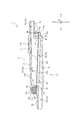
- FIG. 1 is a diagram showing a filtration device 1 for infusion as an embodiment of the filtration device according to the present disclosure.
- FIG. 1 is a top view of the filtration device 1.
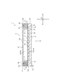
- 2 and 3 are cross-sectional views of the filtration device 1.
- FIG. 2 is a cross-sectional view taken along the line I-I of FIG.
- FIG. 3 is a cross-sectional view taken along the line II-II of FIG.
- the filtration device 1 includes a housing 2 and a filtration sheet 3.
- the thickness direction of the filtration sheet 3 is simply referred to as "thickness direction A”.
- sheet extending direction B the direction orthogonal to the thickness direction of the filtration sheet 3 is simply referred to as "sheet extending direction B”.
- the housing 2 partitions the liquid flow path 2a.
- the filtration sheet 3 separates the liquid flow path 2a into a flow path upstream side and a flow path downstream side.
- the filtration sheet 3 is a filter that removes foreign substances in the liquid.
- the housing 2 includes a first housing member 11, a second housing member 12, and a joining member 13.
- the first housing member 11 and the second housing member 12 sandwich the filtration sheet 3.
- the joining member 13 joins the first housing member 11 and the second housing member 12 in a state where the filtration sheet 3 is sandwiched between the first housing member 11 and the second housing member 12.
- the first housing member 11 and the second housing member 12 are not in contact with each other at a position outside the sheet extending direction B with respect to the outer edge 3a of the filtration sheet 3. That is, although the first housing member 11 and the second housing member 12 sandwich the filtration sheet 3 from both sides in the thickness direction A, they are not in direct contact with each other at a position where the filtration sheet 3 does not intervene between them.
- the joining member 13 has a gap 60 between the first housing member 11 and the second housing member 12 at a position outside the sheet extending direction B with respect to the outer edge 3a of the filtration sheet 3. Is sealed. That is, the joining member 13 joins the first housing member 11 and the second housing member 12, and at a position outside the sheet extending direction B from the outer edge 3a of the filtration sheet 3, the first housing member 11 and the second housing member 12 The gap 60 between the housing members 12 is sealed.
- the first housing member 11 and the second housing member 12 that do not come into direct contact with each other, the first housing that comes into direct contact with each other and positions each other.
- the fixing strength of the filtration sheet 3 can be increased as compared with the configuration using the member and the second housing member.
- the first housing member 11 and the second housing member 12 in a state of sandwiching the filtration sheet 3 are joined by the joining member 13 on the outside of the outer edge 3a of the filtration sheet 3 in the sheet extending direction B. ..
- the positional relationship between the first housing member 11 and the second housing member 12 is determined by the joining member 13.
- the housing 2 capable of increasing the fixing strength of the filtration sheet 3 can be realized.
- the filtration device 1 of the present embodiment includes a ventilation sheet 4 in addition to the housing 2 and the filtration sheet 3 described above.
- the housing 2 of the present embodiment includes a first housing member 11, a second housing member 12, and a joining member 13.
- the first housing member 11 of the present embodiment has a top plate portion 21, an annular protrusion 22 projecting from the top plate portion 21, and an annular protrusion 22 projecting outward in the radial direction.
- An inflow port portion 23 is provided.
- the top plate portion 21 has a substantially circular flat outer shape.
- the top plate portion 21 has a central portion 21b that is radially inside the position where the annular protrusion 22 is projected and an outer edge portion 21c that is radially outward from the position where the annular protrusion 22 is projected. And.
- the top plate portion 21 partitions an opening 21a capable of discharging the gas in the liquid flow path 2a to the outside.
- the opening 21a of the present embodiment is formed in the central portion 21b of the top wall portion 21.
- the lower surface side of the opening 21a, which is the liquid flow path 2a side, is covered with a ventilation sheet 4 described later.
- the annular projecting portion 22 projects from the lower surface of the top plate portion 21 toward the second housing member 12.
- the filtration sheet 3 of the present embodiment is sandwiched between the tip surface of the annular protrusion 22 and the upper surface of the second housing member 12 described later, and is sandwiched and compressed.
- the inflow port portion 23 is a tubular portion that protrudes radially outward from the annular projecting portion 22, and internally partitions the liquid inflow port 23a.
- the liquid inflow port 23a communicates with the flow path upstream side space 11a partitioned by the central portion 21b of the top plate portion 21 and the protruding portion 22 described above. In other words, the liquid inflow port 23a and the flow path upstream side space 11a form a part of the liquid flow path 2a of the housing 2.
- the second housing member 12 of the present embodiment includes a main body plate portion 31 and an outflow port portion 32 projecting from the main body plate portion 31.
- the main body plate portion 31 has a substantially circular flat outer shape.
- the main body plate portion 31 includes a central portion 31b in which a plurality of ribs 31a are formed on the upper surface facing the lower surface of the top plate portion 21 of the first housing member 11, and an outer edge portion 31c in which the ribs 31a are not formed on the upper surface. , Equipped with.
- the rib 31a formed in the central portion 31b extends substantially linearly.
- the extending directions of the plurality of ribs 31a are substantially parallel.
- the plurality of ribs 31a are arranged at predetermined intervals.
- the filtration sheet 3 is supported by the tops of the plurality of ribs 31a. Then, the liquid that has passed through the filtration sheet 3 flows into the groove space as the flow path downstream side space 12a between the plurality of ribs 31a.
- the outer edge portion 31c together with the annular protruding portion 22 of the first housing member 11, constitutes a sandwiching portion that sandwiches the filtration sheet 3. Specifically, the filtration sheet 3 is sandwiched between the tip surface of the annular protrusion 22 of the first housing member 11 and the upper surface of the outer edge portion 31c of the main body plate portion 31 of the second housing member 12.
- the upper surface of the outer edge portion 31c is formed so as to be flush with the virtual plane passing through the tops of the plurality of ribs 31a of the central portion 31b.
- the outflow port portion 32 is a tubular portion that protrudes outward in the radial direction of the main body plate portion 31, and partitions the liquid outlet 32a inside.
- the liquid outlet 32a communicates with the groove space as the above-mentioned space 12a on the downstream side of the flow path. In other words, the liquid outlet 32a and the flow path downstream space 12a form a part of the liquid flow path 2a of the housing 2.
- the liquid flow path 2a of the housing 2 of the present embodiment is composed of the liquid inflow port 23a, the flow path upstream side space 11a, the flow path downstream side space 12a, and the liquid outflow port 32a.
- the liquid flowing in from the liquid inflow port 23a passes through the filtration sheet 3 from the flow path upstream side space 11a, enters the groove space as the flow path downstream side space 12a, and flows out from the liquid outflow port 32a to the outside.
- the joining member 13 of the present embodiment is located in the gap 60 between the first housing member 11 and the second housing member 12, and is joined to the first housing member 11 and the second housing member 12, respectively.
- the first housing member 11 and the second housing member 12 are joined by the joining member 13.
- the gap 60 between the first housing member 11 and the second housing member 12 is sealed from the outside.
- the liquid flow path 2a can be sealed. That is, by arranging the joining member 13 of the present embodiment in the gap 60, both the joining of the first housing member 11 and the second housing member 12 and the sealing of the gap 60 are realized.
- the joining member 13 of the present embodiment is interposed between the outer edge portion 21c of the top plate portion 21 of the first housing member 11 and the outer edge portion 31c of the main body plate portion 31 of the second housing member 12. ing. More specifically, the joining member 13 of the present embodiment includes an outer edge portion 21c of the top plate portion 21 of the first housing member 11, an annular protruding portion 22 of the first housing member 11, and a main body of the second housing member 12. It is arranged over the entire circumferential direction in the annular groove including the gap 60, which is composed of the outer edge portion 31c of the plate portion 31. As a result, the gap 60 is sealed by the joining member 13 over the entire circumferential direction.
- the first housing member 11, the second housing member 12, and the joining member 13 of the present embodiment are made of a resin material. Then, the first housing member 11, the second housing member 12, and the joining member 13 are joined by welding such as fusion. By doing so, after molding the first housing member 11 and the second housing member 12, the molding material is filled in the gap 60 and solidified to join the first housing member 11 and the second housing member 12 and to solidify the molding material. , And the sealing of the void 60 can be realized together, and the joining member 13 can be formed. Specifically, the heat of the molding material of the joining member 13 melts the first housing member 11 and the second housing member 12, fuses them with the joining member 13, and seals the gap 60.
- Examples of the material of the first housing member 11, the second housing member 12, and the joining member 13 include polyolefins such as polyethylene, polypropylene, and ethylene-propylene copolymer; ethylene-vinyl acetate copolymer (EVA); polyvinyl chloride.
- polyolefins such as polyethylene, polypropylene, and ethylene-propylene copolymer
- EVA ethylene-vinyl acetate copolymer
- polyvinyl chloride polyvinyl chloride
- the resin materials constituting the first housing member 11, the second housing member 12, and the joining member 13 of the present embodiment can be appropriately selected from the various resin materials listed above, and are, for example, the same material such as polycarbonate. Is preferable. By doing so, the bonding strength of the welding of the first housing member 11, the second housing member 12, and the bonding member 13 can be increased.
- the joining member 13 of the present embodiment joins the first housing member 11 and the second housing member 12 by welding to the first housing member 11 and the second housing member 12, but the first The configuration is not particularly limited as long as the housing member 11 and the second housing member 12 can be joined and the gap 60 can be sealed.
- the joining member 13 is located in the gap 60 between the first housing member 11 and the second housing member 12 and is joined to the first housing member 11 and the second housing member 12, respectively.
- the housing 2 can be easily miniaturized as compared with the configuration in which the joining member is provided outside the gap 60.
- the joining member 13 of the present embodiment is entirely arranged in the annular groove including the gap 60, but may be a joining member in which a part of the joining member 13 protrudes from the annular groove.
- the housing 2 of the present embodiment is composed of the above-mentioned first housing member 11, the second housing member 12, and the joining member 13, but members other than these members may be further provided.
- the specific shapes of the first housing member 11, the second housing member 12, and the joining member 13 are not limited to the above-mentioned shapes, and may be different shapes.
- the first housing member 11 partitions the liquid inflow port 23a of the liquid flow path 2a.
- the second housing member 12 partitions the liquid outlet 32a of the liquid flow path 2a.
- the first housing member may partition the liquid outlet and the second housing member may partition the liquid inlet.
- only one of the first housing member 11 and the second housing member 12 may partition the liquid inlet and the liquid outlet.
- the first housing member is the liquid inlet and the fluid flow of the liquid flow path. It is preferable that one of the outlets is partitioned and the second housing member partitions the other of the liquid inlet and the liquid outlet of the liquid flow path.
- the first housing member 11 is provided with the protruding portion 22 for sandwiching the filtration sheet 3, and the second housing member 12 is not provided with the protruding portion for sandwiching the filtration sheet 3.
- the second housing member 12 may include a protrusion for sandwiching the filtration sheet 3.
- neither the first housing member 11 nor the second housing member 12 may be configured to have a protrusion for sandwiching the filtration sheet 3.
- first housing member 11 and the second housing member 12 are each formed by one component, but the present invention is not limited to this configuration, and the first housing member 11 and the second housing member 12 are formed by combining two or more components. May be good.
- the filtration sheet 3 of the present embodiment is a hydrophilic filter having a substantially circular outer shape.
- a hydrophilic porous membrane, a hydrophilic non-woven fabric, or the like can be used as the hydrophilic filter as the filtration sheet 3.
- the material of the filtration sheet 3 include hydrophilic materials such as polysulfone, cellulose acetate, and nitrocellulose.
- the filtration sheet 3 may be formed by hydrophilizing a hydrophobic filter made of a hydrophobic material such as polypropylene, polyethylene, polyester or polytetrafluoroethylene.
- the filtration sheet 3 of the present embodiment has a substantially circular outer shape.
- the filtration sheet 3 of the present embodiment includes a sandwiched portion 41 sandwiched between the first housing member 11 and the second housing member 12, a liquid passing portion 42 located radially inside the sandwiched portion 41, and a cover.
- An outer edge portion 43 extending radially outward of the sandwiching portion 41 is provided.
- the sandwiched portion 41 of the present embodiment includes the tip surface of the annular protruding portion 22 of the first housing member 11 and the upper surface of the outer edge portion 31c of the main body plate portion 31 of the second housing member 12 of the filtration sheet 3. It is a part that comes into contact with and is compressed and sandwiched between them. That is, the filtration sheet 3 of the present embodiment is sandwiched between the first housing member 11 and the second housing member 12 at the position of the protruding portion 22. In this way, by configuring the filtration sheet 3 to be sandwiched at the position of the protruding portion 22, the radial range of the sandwiched portion 41 of the filtration sheet 3 can be narrowed.
- the compressive force applied from the first housing member 11 and the second housing member 12 to the sandwiched portion 41 of the filtration sheet 3 becomes difficult to disperse, and the compression force applied to the sandwiched portion 41 of the filtration sheet 3 becomes more rigid between the first housing member 11 and the second housing member 12.
- the filtration sheet 3 can be fixed.
- the liquid passing portion 42 of the present embodiment is located inside the sandwiched portion 41 in a plan view of the filtration sheet 3 in the thickness direction A.
- the liquid passing portion 42 is located in the liquid flow path 2a and is a portion for removing foreign matter in the passing liquid.
- the liquid passing portion 42 of the present embodiment is supported by the tops of a plurality of ribs 31a provided on the upper surface of the central portion 31b of the main body plate portion 31 of the second housing member 12.
- the liquid filtered from the space 11a on the upstream side of the flow path of the liquid flow path 2a partitioned by the first housing member 11 through the liquid passage portion 42 of the filtration sheet 3 is a flow partitioned by the second housing member 12. It enters the groove space between the plurality of ribs 31a as the road downstream side space 12a.
- the outer edge portion 43 of the present embodiment is located outside the sandwiched portion 41 in a plan view of the filtration sheet 3 in the thickness direction A.
- the first housing member 11 and the second housing member 12 of the present embodiment do not sandwich the outer edge 3a of the filtration sheet 3, but sandwich the position inside the outer edge 3a. Therefore, the filtration sheet 3 of the present embodiment includes an outer edge portion 43 extending radially outward from the sandwiched portion 41.
- the outer edge portion 43 of the present embodiment is joined to the joining member 13. Specifically, the outer edge portion 43 of the present embodiment includes a lower surface of the outer edge portion 21c of the top plate portion 21 of the first housing member 11 and an upper surface of the outer edge portion 31c of the main body plate portion 31 of the second housing member 12. It is located in between. Further, in a plan view in the thickness direction A, the outer edge 3a of the filtration sheet 3 is the outer edge 21d of the top plate portion 21 of the first housing member 11 and the outer edge 31d of the main body plate portion 31 of the second housing member 12. It does not protrude outward in the sheet extending direction B.
- the joining member 13 of the present embodiment is not only located in the gap 60 outside the sheet extending direction B from the outer edge 3a of the filtration sheet 3, but also from the gap 60, the sheet is more than the outer edge 3a of the filtration sheet 3. A part of it penetrates to the inside of the extending direction B.
- the joining member 13 of the present embodiment is joined not only to the first housing member 11 and the second housing member 12 but also to the outer edge portion 43 of the filtration sheet 3 by welding. In this way, by forming the joining member 13 to be joined not only to the first housing member 11 and the second housing member 12 but also to the outer edge portion 43 of the filtration sheet 3, the filtration sheet 3 is made stronger. Can be fixed.
- the joining member 13 of the present embodiment is welded to the upper surface of the outer edge portion 43 of the filtration sheet 3 on the first housing member 11 side and the outer peripheral end surface, but the filtration sheet. It is sufficient that it is welded to at least one of the upper surface, the outer peripheral end surface, and the lower surface of the outer edge portion 43 of No. 3, and the welding position is not particularly limited.
- the single-layer filtration sheet 3 is sandwiched between the first housing member 11 and the second housing member 12, but the present invention is not limited to this configuration, and for example, a plurality of laminated layers
- the filtration sheet 3 may be sandwiched between the first housing member 11 and the second housing member 12.
- the ventilation sheet 4 of the present embodiment covers the opening 21a in which the gas can be discharged in the liquid flow path 2a, which is partitioned by the first housing member 11. More specifically, the ventilation sheet 4 is attached to the lower surface of the top plate portion 21 of the first housing member 11 on the liquid flow path 2a side so as to cover the opening 21a.
- the ventilation sheet 4 can be attached to the lower surface of the top plate portion 21 by various methods, and may be, for example, welded by a heat seal or the like or adhered by an adhesive or the like.
- the ventilation sheet 4 is a hydrophobic filter.
- the ventilation sheet 4 has a non-permeable property, allows the outflow of gas from the opening 21a, and prevents the outflow of liquid from the opening 21a.
- a hydrophobic porous membrane or a hydrophobic non-woven fabric can be used as the ventilation sheet 4, for example.
- the material of the ventilation sheet 4 include hydrophobic materials such as polypropylene, polyethylene, polysulfone, polyacrylonitrile, polytetrafluoroethylene, and cellulose acetate.
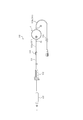
- the infusion set 110 including the filtration device 1 of the present embodiment will be described.
- the infusion set 110 can form an infusion line that connects an infusion bag (not shown in FIG. 4) to an indwelling needle (not shown in FIG. 4).
- the infusion set 110 includes a plurality of infusion tubes 111, a drip tube 112 capable of visually recognizing the flow rate of the infusion solution supplied from the infusion bag, and a clamp 113 for adjusting the flow rate of the infusion solution in the infusion tube 111.
- the filtration device 1 the connector 114 for connecting the infusion tubes 111 to each other, and the one-touch clamp 115 for closing the infusion tube 111.
- the inflow port portion 23 of the filtration device 1 is tightly connected to the first infusion tube 111a on the upstream side of the flow path. Further, the outflow port portion 32 of the filtration device 1 is tightly connected to the second infusion tube 111b on the downstream side of the flow path.
- the liquid in the infusion bag flows from the hollow portion of the first infusion tube 111a into the liquid flow path 2a of the filtration device 1, is filtered by the filtration sheet 3 (see FIGS. 2 and 3), and is filtered by the second infusion solution. It flows out into the hollow portion of the tube 111b and is sent to the indwelling needle.
- the position of the filtration device 1 in the infusion set 110 is not limited to the position shown in FIG. In FIG. 4, the filtration device 1 is arranged on the downstream side of the flow path of the connector 114, but may be arranged on the upstream side of the flow path of the connector 114, for example.
- the infusion set 110 shown in FIG. 4 includes a plurality of infusion tubes 111, an infusion tube 112, a clamp 113, a filtration device 1, a connector 114, and a one-touch clamp 115, but includes at least one infusion tube 111 and a filtration device 1.
- Any configuration may be provided, and the configuration is not limited to that shown in FIG. Therefore, for example, an infusion set without the connector 114 may be used.
- the filtration device according to the present disclosure is not limited to the specific configuration described in the above-described embodiment, and can be variously modified or changed as long as it does not deviate from the claims.
- the filtration device 1 for infusion solution has been described, but the filtration device according to the present disclosure is applicable to the filtration device for hemodialysis and the filtration device for removing leukocytes, as described above.
- the manufacturing method of the filtration device 1 described above is not particularly limited, but it can be manufactured by using, for example, die slide molding.
- This disclosure relates to a filtration device.
- Filtration device 2 Housing 2a: Liquid flow path 3: Filtration sheet 3a: Outer edge of filtration sheet 4: Ventilation sheet 11: First housing member 11a: Flow path upstream side space 12: Second housing member 12a: Flow path downstream Side space 13: Joining member 21: Top wall portion 21a: Opening portion 21b: Central portion 21c: Outer edge portion 21d: Outer edge 22: Protruding portion 23: Inflow port portion 23a: Liquid inflow port 31: Main body plate portion 31a: Rib 31b: Central portion 31c: Outer edge portion 31d: Outer edge 32: Outflow port portion 32a: Liquid outlet 41: Holded portion 42: Liquid flow portion 43: Outer edge portion 60: Void 110: Infusion set 111: Infusion tube 111a: First infusion tube 111b: Second infusion tube 112: Drip tube 113: Clamp 114: Connector 115: One-touch clamp A: Filtration sheet thickness direction B: Filtration sheet sheet extension direction
Abstract
本開示に係る濾過装置は、液体流路を区画するハウジングと、前記液体流路を流路上流側と流路下流側とに隔てる濾過シートと、を備える濾過装置であって、前記ハウジングは、前記濾過シートを挟持する第1ハウジング部材及び第2ハウジング部材と、前記濾過シートが前記第1ハウジング部材及び前記第2ハウジング部材に挟持されている状態で、前記第1ハウジング部材及び前記第2ハウジング部材を接合する接合部材と、を備え、前記第1ハウジング部材及び前記第2ハウジング部材は、前記濾過シートの外縁よりも外側の位置で互いに接触しておらず、前記接合部材は、前記濾過シートの前記外縁よりも外側の位置で、前記第1ハウジング部材及び前記第2ハウジング部材の間の空隙を封止している。
Description
本開示は濾過装置に関する。
現在、液体中の異物を除去するために、各種の医療用の濾過装置が使用されている。特許文献1には、この種の濾過装置が記載されている。特許文献1に記載の濾過装置は、濾過シートとしての親水性フィルタを備える。
また、特許文献2には、濾過装置としての血液処理フィルタが開示されている。特許文献2の血液処理フィルタは入口側容器材及び出口側容器材を備える。特許文献2の入口側容器材及び出口側容器材の端面を含む外縁部には、互いに接合して接合部を構成する入口側接合部及び出口側接合部がそれぞれ設けられている。また、入口側容器材及び出口側容器材には、入口側接合部及び出口側接合部の内縁に、濾過シートとしてのフィルタ要素の外縁部を把持する入口側把持部及び出口側把持部がそれぞれ設けられている。
特許文献1に記載の濾過シートとしての親水性フィルタは、筺体ハウジング上に支持されている。これに対して、特許文献2に記載されている濾過シートとしてのフィルタ要素は、入口側把持部及び出口側把持部により把持されている。そのため、特許文献2に記載のフィルタ要素は位置ずれし難い。しかしながら、濾過シートの固定強度においては依然として改善の余地がある。
本開示は、濾過シートをより強固に固定可能な構成を有する濾過装置を提供することを目的とする。
本開示の第1の態様としての濾過装置は、液体流路を区画するハウジングと、前記液体流路を流路上流側と流路下流側とに隔てる濾過シートと、を備える濾過装置であって、前記ハウジングは、前記濾過シートを挟持する第1ハウジング部材及び第2ハウジング部材と、前記濾過シートが前記第1ハウジング部材及び前記第2ハウジング部材に挟持されている状態で、前記第1ハウジング部材及び前記第2ハウジング部材を接合する接合部材と、を備え、前記第1ハウジング部材及び前記第2ハウジング部材は、前記濾過シートの外縁よりも外側の位置で互いに接触しておらず、前記接合部材は、前記濾過シートの前記外縁よりも外側の位置で、前記第1ハウジング部材及び前記第2ハウジング部材の間の空隙を封止している。
本開示の1つの実施形態として、前記接合部材は、前記第1ハウジング部材及び前記第2ハウジング部材の間の前記空隙に位置し、前記第1ハウジング部材及び前記第2ハウジング部材それぞれに接合されている。
本開示の1つの実施形態として、前記濾過シートは、厚み方向で見た平面視において、前記第1ハウジング部材及び前記第2ハウジング部材により挟持されている被挟持部よりも外側に位置する外縁部を備え、前記接合部材は、前記濾過シートの前記外縁部に接合されている。
本開示の1つの実施形態として、前記第1ハウジング部材及び前記第2ハウジング部材の少なくとも一方の部材は、他方の部材に向かって突出する突出部を備え、前記濾過シートは、前記突出部の位置で、前記第1ハウジング部材及び前記第2ハウジング部材の間に挟持されている。
本開示の1つの実施形態として、前記濾過シートは、親水性フィルタである。
本開示の1つの実施形態として、前記第1ハウジング部材は、前記液体流路内の気体を放出可能な開口部を区画しており、前記開口部を覆う通気シートを備える。
本開示の1つの実施形態として、前記第1ハウジング部材は、前記液体流路の液体流入口及び流体流出口の一方を区画しており、前記第2ハウジング部材は、前記液体流路の前記液体流入口及び前記液体流出口の他方を区画している。
本開示によれば、濾過シートをより強固に固定可能な構成を有する濾過装置を提供することができる。
以下、本開示に係る濾過装置の実施形態について図面を参照して例示説明する。各図において共通する部材・部位には同一の符号を付している。
本開示に係る濾過装置は、医療用の濾過装置として用いることができる。医療用の濾過装置としては、例えば、輸液用の濾過装置、血液透析用の濾過装置、白血球除去用の濾過装置、などが挙げられる。以下、本実施形態では、医療用の濾過装置の一例として、輸液用の濾過装置について例示説明する。
図1は、本開示に係る濾過装置の一実施形態としての輸液用の濾過装置1を示す図である。図1は、濾過装置1の上面図である。図2、図3は濾過装置1の断面図である。図2は、図1のI-I線に沿う断面での断面図である。図3は、図1のII-II線に沿う断面での断面図である。
図1~図3に示すように、濾過装置1は、ハウジング2と、濾過シート3と、を備える。以下、濾過シート3の厚み方向を、単に「厚み方向A」と記載する。また、濾過シート3の厚み方向と直交する方向を、単に「シート延在方向B」と記載する。
図2、図3に示すように、ハウジング2は、液体流路2aを区画している。濾過シート3は、液体流路2aを流路上流側と流路下流側とに隔てている。
液体流路2aを流路上流側から流路下流側に向かって流れる液体中の異物は、濾過シート3を通過することで除去される。つまり、濾過シート3は、液体中の異物を除去するフィルタである。
図2、図3に示すように、ハウジング2は、第1ハウジング部材11と、第2ハウジング部材12と、接合部材13と、を備える。第1ハウジング部材11及び第2ハウジング部材12は、濾過シート3を挟持する。接合部材13は、濾過シート3が第1ハウジング部材11及び第2ハウジング部材12に挟持されている状態で、第1ハウジング部材11及び第2ハウジング部材12を接合する。
図2、図3に示すように、第1ハウジング部材11及び第2ハウジング部材12は、濾過シート3の外縁3aよりもシート延在方向Bの外側の位置で互いに接触していない。つまり、第1ハウジング部材11及び第2ハウジング部材12は、濾過シート3を厚み方向Aの両面から挟み込んでいるが、相互間に濾過シート3が介在しない位置では、互いに直接接触していない。
図2、図3に示すように、接合部材13は、濾過シート3の外縁3aよりもシート延在方向Bの外側の位置で、第1ハウジング部材11及び第2ハウジング部材12の間の空隙60を封止している。つまり、接合部材13は、第1ハウジング部材11及び第2ハウジング部材12を接合すると共に、濾過シート3の外縁3aよりもシート延在方向Bの外側の位置で、第1ハウジング部材11及び第2ハウジング部材12の間の空隙60を封止している。
以上のように、相互間で直接接触しない第1ハウジング部材11及び第2ハウジング部材12の間で濾過シート3を挟持することで、相互間で直接接触して互いの位置決めがなされる第1ハウジング部材及び第2ハウジング部材を用いる構成と比較して、濾過シート3の固定強度を高めることができる。また、濾過シート3を挟持している状態の第1ハウジング部材11及び第2ハウジング部材12は、濾過シート3の外縁3aよりもシート延在方向Bの外側で、接合部材13により接合されている。これにより、濾過シート3が第1ハウジング部材11及び第2ハウジング部材12により挟持された状態を維持したまま、第1ハウジング部材11及び第2ハウジング部材12の相互の位置関係を、接合部材13により固定することができる。これにより、濾過シート3の固定強度を高めることが可能なハウジング2を実現できる。
以下、図1~図3を参照して、本実施形態の濾過装置1の更なる詳細について説明する。本実施形態の濾過装置1は、上述したハウジング2及び濾過シート3に加えて、通気シート4を備える。
[ハウジング2]
本実施形態のハウジング2は、上述したように、第1ハウジング部材11、第2ハウジング部材12及び接合部材13を備える。
本実施形態のハウジング2は、上述したように、第1ハウジング部材11、第2ハウジング部材12及び接合部材13を備える。
本実施形態の第1ハウジング部材11は、天板部21と、この天板部21から突設されている環状の突出部22と、この環状の突出部22から径方向外側に向かって突出する流入ポート部23と、を備える。
天板部21は、略円形扁平状の外形を有している。天板部21は、環状の突出部22が突設されている位置よりも径方向内側の中央部21bと、環状の突出部22が突設されている位置よりも径方向外側の外縁部21cと、を備える。
天板部21は、液体流路2a内の気体を外部に放出可能な開口部21aを区画している。具体的に、本実施形態の開口部21aは、天壁部21の中央部21bに形成されている。この開口部21aの液体流路2a側である下面側は、後述する通気シート4により覆われている。
環状の突出部22は、天板部21の下面から、第2ハウジング部材12に向かって突出している。詳細は後述するが、本実施形態の濾過シート3は、環状の突出部22の先端面と、後述する第2ハウジング部材12の上面と、の間で挟み込まれ、挟持・圧縮される。
流入ポート部23は、環状の突出部22から径方向外側に突出する筒状部であり、内部に液体流入口23aを区画している。この液体流入口23aは、上述の天板部21の中央部21bと、突出部22と、により区画される流路上流側空間11aに連通している。換言すれば、液体流入口23a及び流路上流側空間11aは、ハウジング2の液体流路2aの一部を構成している。
本実施形態の第2ハウジング部材12は、本体板部31と、この本体板部31から突設されている流出ポート部32と、を備える。
本体板部31は、略円形扁平状の外形を有している。本体板部31は、第1ハウジング部材11の天板部21の下面と対向する上面において複数のリブ31aが形成されている中央部31bと、上面においてリブ31aが形成されていない外縁部31cと、を備える。
中央部31bに形成されているリブ31aは略直線状に延在している。複数のリブ31aの延在方向は略平行である。複数のリブ31aは、所定間隔を空けて配置されている。濾過シート3は、複数のリブ31aの頂部により支持される。そして、濾過シート3を通過した液体は、複数のリブ31aの間の流路下流側空間12aとしての溝空間に流れ込む。
外縁部31cは、第1ハウジング部材11の環状の突出部22と共に、濾過シート3を挟持する挟持部を構成する。具体的に、濾過シート3は、第1ハウジング部材11の環状の突出部22の先端面と、第2ハウジング部材12の本体板部31の外縁部31cの上面と、との間で挟み込まれる。本実施形態では、外縁部31cの上面は、中央部31bの複数のリブ31aの頂部を通過する仮想平面と、面一となるように形成されている。
流出ポート部32は、本体板部31の径方向外側に突出する筒状部であり、内部に液体流出口32aを区画している。この液体流出口32aは、上述の流路下流側空間12aとしての溝空間に連通している。換言すれば、液体流出口32a及び流路下流側空間12aは、ハウジング2の液体流路2aの一部を構成している。
したがって、本実施形態のハウジング2の液体流路2aは、液体流入口23a、流路上流側空間11a、流路下流側空間12a、及び、液体流出口32aにより構成されている。液体流入口23aから流入した液体は、流路上流側空間11aから濾過シート3を通過して流路下流側空間12aとしての溝空間に入り込み、液体流出口32aから外部に流出する。
本実施形態の接合部材13は、第1ハウジング部材11と第2ハウジング部材12との間の空隙60に位置し、第1ハウジング部材11及び第2ハウジング部材12それぞれに接合されている。換言すれば、第1ハウジング部材11及び第2ハウジング部材12は、接合部材13により、接合されている。更に、これにより、第1ハウジング部材11と第2ハウジング部材12との間の空隙60は外部から封止される。その結果、液体流路2aを密閉することができる。つまり、本実施形態の接合部材13は、空隙60に配置されることで、第1ハウジング部材11及び第2ハウジング部材12の接合、並びに、空隙60の封止、を共に実現している。
具体的に、本実施形態の接合部材13は、第1ハウジング部材11の天板部21の外縁部21cと、第2ハウジング部材12の本体板部31の外縁部31cと、の間に介在している。より具体的に、本実施形態の接合部材13は、第1ハウジング部材11の天板部21の外縁部21cと、第1ハウジング部材11の環状の突出部22と、第2ハウジング部材12の本体板部31の外縁部31cと、で構成される、上記空隙60を含む環状溝内で、周方向全域に亘って配置されている。これにより、空隙60は、周方向全域に亘って接合部材13により封止される。
本実施形態の第1ハウジング部材11、第2ハウジング部材12及び接合部材13は、樹脂材料により構成されている。そして、第1ハウジング部材11、第2ハウジング部材12及び接合部材13は、例えば融着などの溶着により接合される。このようにすることで、第1ハウジング部材11及び第2ハウジング部材12を成形後に、成形材料を空隙60に充填し固化させることで、第1ハウジング部材11及び第2ハウジング部材12の接合、及び、空隙60の封止、を共に実現可能な接合部材13を成形することができる。具体的には、接合部材13の成形材料の熱により、第1ハウジング部材11及び第2ハウジング部材12が溶融して、接合部材13と融着すると共に、空隙60が封止される。
第1ハウジング部材11、第2ハウジング部材12及び接合部材13の材料としては、例えば、ポリエチレン、ポリプロピレン、エチレン-プロピレン共重合体等のポリオレフィン;エチレン-酢酸ビニル共重合体(EVA);ポリ塩化ビニル;ポリ塩化ビニリデン;ポリスチレン;ポリアミド;ポリイミド;ポリアミドイミド;ポリカーボネート;ポリ-(4-メチルペンテン-1);アイオノマー;アクリル樹脂;ポリメチルメタクリレート;アクリロニトリル-ブタジエン-スチレン共重合体(ABS樹脂);アクリロニトリル-スチレン共重合体(AS樹脂);ブタジエン-スチレン共重合体;ポリエチレンテレフタレート(PET)、ポリブチレンテレフタレート(PBT)、ポリシクロヘキサンテレフタレート(PCT)等のポリエステル;ポリエーテル;ポリエーテルケトン(PEK);ポリエーテルエーテルケトン(PEEK);ポリエーテルイミド;ポリアセタール(POM);ポリフェニレンオキシド;変性ポリフェニレンオキシド;ポリサルフォン;ポリエーテルサルフォン;ポリフェニレンサルファイド;ポリアリレート;芳香族ポリエステル(液晶ポリマー);ポリテトラフルオロエチレン、ポリフッ化ビニリデン、その他フッ素系樹脂;などの各種樹脂材料が挙げられる。
本実施形態の第1ハウジング部材11、第2ハウジング部材12及び接合部材13を構成する樹脂材料は、上記列挙した各種樹脂材料から適宜選択可能であるが、例えば、ポリカーボネートなどの同一材料とすることが好ましい。このようにすることで、第1ハウジング部材11、第2ハウジング部材12及び接合部材13の溶着の接合強度を高めることができる。
このように、本実施形態の接合部材13は、第1ハウジング部材11及び第2ハウジング部材12と溶着することで、第1ハウジング部材11及び第2ハウジング部材12を接合しているが、第1ハウジング部材11及び第2ハウジング部材12を接合すると共に、空隙60を封止可能であれば、その構成は特に限定されない。但し、本実施形態のように、第1ハウジング部材11及び第2ハウジング部材12の間の空隙60に位置し、第1ハウジング部材11及び第2ハウジング部材12それぞれに接合されている接合部材13とすることで、空隙60の外部に接合部材を設ける構成と比較して、ハウジング2を小型化し易くなる。
また、本実施形態の接合部材13は、空隙60を含む環状溝内に全てが配置されているが、一部が環状溝からはみ出している接合部材としてもよい。
以上のように、本実施形態のハウジング2は、上述の第1ハウジング部材11、第2ハウジング部材12及び接合部材13により構成されているが、これら部材以外の部材を更に備えてもよい。
また、第1ハウジング部材11、第2ハウジング部材12及び接合部材13の具体的な形状は、上述した形状に限定されず、異なる形状としてもよい。例えば、本実施形態では、第1ハウジング部材11は、液体流路2aの液体流入口23aを区画している。また、第2ハウジング部材12は、液体流路2aの液体流出口32aを区画している。これに対して、第1ハウジング部材が液体流出口を区画し、第2ハウジング部材が液体流入口を区画していてもよい。また、第1ハウジング部材11及び第2ハウジング部材12のいずれか一方のみが、液体流入口及び液体流出口を区画していてもよい。但し、本実施形態のように、濾過シート3を第1ハウジング部材11及び第2ハウジング部材12で挟持する構成とする場合には、第1ハウジング部材が、液体流路の液体流入口及び流体流出口の一方を区画し、かつ、第2ハウジング部材が、液体流路の液体流入口及び液体流出口の他方を区画することが好ましい。このようにすることで、ハウジング2の構成、及び、ハウジング2が区画する液体流路2aの経路構成を、簡素化できる。
更に、本実施形態では、第1ハウジング部材11が、濾過シート3を挟持する突出部22を備え、第2ハウジング部材12が、濾過シート3を挟持する突出部を備えない構成としたが、この構成に限定されない。つまり、第1ハウジング部材11が突出部22を備えることに代えて又は加えて、第2ハウジング部材12が、濾過シート3を挟持するための突出部を備えてもよい。更に、第1ハウジング部材11及び第2ハウジング部材12のいずれもが、濾過シート3を挟持する突出部を備えない構成であってもよい。但し、本実施形態のように、第1ハウジング部材11及び第2ハウジング部材12の少なくとも一方の部材は、他方の部材に向かって突出する突出部を備えることが好ましい。このようにすることで、濾過シート3を、より強固に固定することができる。この詳細は後述する。
更に、本実施形態では、第1ハウジング部材11及び第2ハウジング部材12が、それぞれ1つの部品により形成されているが、この構成に限定されず、2つ以上の部品を組み合わせることにより形成されてもよい。
[濾過シート3]
本実施形態の濾過シート3は、略円形の外形を有する親水性フィルタである。濾過シート3としての親水性フィルタは、例えば、親水性多孔質膜、親水性不織布などを使用できる。濾過シート3の材料としては、例えば、ポリスルホン、酢酸セルロース、ニトロセルロースなどの親水性材料が挙げられる。また、濾過シート3は、ポリプロピレン、ポリエチレン、ポリエステル、ポリテトラフルオロエチレンなどの疎水性材料から構成された疎水性フィルタを親水化処理することで形成してもよい。
本実施形態の濾過シート3は、略円形の外形を有する親水性フィルタである。濾過シート3としての親水性フィルタは、例えば、親水性多孔質膜、親水性不織布などを使用できる。濾過シート3の材料としては、例えば、ポリスルホン、酢酸セルロース、ニトロセルロースなどの親水性材料が挙げられる。また、濾過シート3は、ポリプロピレン、ポリエチレン、ポリエステル、ポリテトラフルオロエチレンなどの疎水性材料から構成された疎水性フィルタを親水化処理することで形成してもよい。
本実施形態の濾過シート3は、略円形の外形を有する。本実施形態の濾過シート3は、第1ハウジング部材11及び第2ハウジング部材12により挟持されている被挟持部41と、この被挟持部41の径方向内側に位置する通液部42と、被挟持部41の径方向外側に延在している外縁部43と、を備える。
本実施形態の被挟持部41は、濾過シート3のうち、第1ハウジング部材11の環状の突出部22の先端面と、第2ハウジング部材12の本体板部31の外縁部31cの上面と、とに接触し、これらに圧縮されて挟み込まれている部分である。つまり、本実施形態の濾過シート3は、突出部22の位置で、第1ハウジング部材11及び第2ハウジング部材12の間に挟持されている。このように、突出部22の位置で濾過シート3を挟持する構成とすることで、濾過シート3の被挟持部41の径方向範囲を狭くできる。そのため、第1ハウジング部材11及び第2ハウジング部材12から濾過シート3の被挟持部41に加わる圧縮力が分散し難くなり、第1ハウジング部材11及び第2ハウジング部材12の間で、より強固に濾過シート3を固定することができる。
本実施形態の通液部42は、濾過シート3を厚み方向Aで見た平面視において、被挟持部41の内側に位置している。通液部42は、液体流路2a内に位置し、通過する液体中の異物を除去する部分である。本実施形態の通液部42は、第2ハウジング部材12の本体板部31の中央部31bの上面に設けられている複数のリブ31aの頂部に支持されている。第1ハウジング部材11により区画される液体流路2aの流路上流側空間11aから、濾過シート3の通液部42を通過して濾過された液体は、第2ハウジング部材12により区画される流路下流側空間12aとしての、複数のリブ31a間の溝空間に入り込む。
本実施形態の外縁部43は、濾過シート3を厚み方向Aで見た平面視において、被挟持部41の外側に位置している。換言すれば、本実施形態の第1ハウジング部材11及び第2ハウジング部材12は、濾過シート3の外縁3aを挟持しておらず、外縁3aよりも内側の位置を挟持している。そのため、本実施形態の濾過シート3は、被挟持部41よりも径方向外側に延在する外縁部43を備えている。
本実施形態の外縁部43は、接合部材13と接合されている。具体的に、本実施形態の外縁部43は、第1ハウジング部材11の天板部21の外縁部21cの下面と、第2ハウジング部材12の本体板部31の外縁部31cの上面と、の間に位置している。また、厚み方向Aで見た平面視において、濾過シート3の外縁3aは、第1ハウジング部材11の天板部21の外縁21d、及び、第2ハウジング部材12の本体板部31の外縁31d、よりもシート延在方向Bにおいて外側に突出していない。そして、本実施形態の接合部材13は、濾過シート3の外縁3aよりもシート延在方向Bの外側の空隙60に位置するのみならず、その空隙60から、濾過シート3の外縁3aよりもシート延在方向Bの内側まで一部が入り込んでいる。これにより、本実施形態の接合部材13は、第1ハウジング部材11及び第2ハウジング部材12のみならず、濾過シート3の外縁部43に対しても、溶着により接合されている。このように、接合部材13が、第1ハウジング部材11及び第2ハウジング部材12のみならず、濾過シート3の外縁部43にも接合される構成とすることで、濾過シート3を、より強固に固定することができる。
図2、図3に示すように、本実施形態の接合部材13は、濾過シート3の外縁部43の第1ハウジング部材11側の上面、及び、外周端面、に溶着されているが、濾過シート3の外縁部43の上面、外周端面、及び、下面の少なくともいずれかと溶着されていればよく、その溶着位置は特に限定されない。
また、本実施形態の濾過装置1では、単層の濾過シート3が、第1ハウジング部材11及び第2ハウジング部材12により挟持されているが、この構成に限られず、例えば、積層させた複数層の濾過シート3が、第1ハウジング部材11及び第2ハウジング部材12により挟持される構成としてもよい。
[通気シート4]
本実施形態の通気シート4は、第1ハウジング部材11が区画する、液体流路2a内の気体を放出可能な開口部21aを覆っている。より具体的に、通気シート4は、第1ハウジング部材11の天板部21の液体流路2a側の下面に、開口部21aを覆うように取り付けられている。通気シート4は、天板部21の下面に対して、各種方法により取り付け可能であり、例えば、ヒートシール等による溶着であっても、接着剤等による接着であってもよい。
本実施形態の通気シート4は、第1ハウジング部材11が区画する、液体流路2a内の気体を放出可能な開口部21aを覆っている。より具体的に、通気シート4は、第1ハウジング部材11の天板部21の液体流路2a側の下面に、開口部21aを覆うように取り付けられている。通気シート4は、天板部21の下面に対して、各種方法により取り付け可能であり、例えば、ヒートシール等による溶着であっても、接着剤等による接着であってもよい。
通気シート4は疎水性フィルタである。通気シート4は、非透水性を有しており、開口部21aからの気体の流出を許容し、開口部21aからの液体の流出を阻止する。通気シート4は、例えば、疎水性多孔質膜または疎水性不織布などを使用できる。通気シート4の材料としては、例えば、ポリプロピレン、ポリエチレン、ポリスルホン、ポリアクリロニトリル、ポリテトラフルオロエチレン、セルロースアセテート等の疎水性材料が挙げられる。
次に、図4を参照して、本実施形態の濾過装置1を備える輸液セット110について説明する。
輸液セット110は、図4において図示しない輸液バッグから、図4において同じく図示しない留置針までを接続する輸液ラインを形成することができる。具体的に、輸液セット110は、複数の輸液チューブ111と、輸液バッグから供給される輸液剤の流量を視認可能な点滴筒112と、輸液チューブ111内の輸液剤の流量を調整するクランプ113と、濾過装置1と、輸液チューブ111同士を接続するコネクタ114と、輸液チューブ111を閉塞するワンタッチクランプ115と、を備える。
図4に示す輸液セット110では、濾過装置1の流入ポート部23が、流路上流側の第1輸液チューブ111aと液密に接続されている。また、濾過装置1の流出ポート部32が、流路下流側の第2輸液チューブ111bと液密に接続されている。これにより、輸液バッグの液体は、第1輸液チューブ111aの中空部から、濾過装置1の液体流路2a内に流入し、濾過シート3(図2、図3参照)により濾過され、第2輸液チューブ111bの中空部へと流出し、留置針まで送液される。
輸液セット110における濾過装置1の位置は、図4に示す位置に限られない。図4では、濾過装置1がコネクタ114の流路下流側に配置されているが、例えば、コネクタ114の流路上流側に配置されていてもよい。
また、図4に示す輸液セット110は、複数の輸液チューブ111、点滴筒112、クランプ113、濾過装置1、コネクタ114及びワンタッチクランプ115を備えるが、少なくとも1つの輸液チューブ111と、濾過装置1と、を備える構成であればよく、図4の構成に限られない。したがって、例えば、コネクタ114を備えない輸液セットとしてもよい。
本開示に係る濾過装置は、上述した実施形態に記載した具体的な構成に限られず、請求の範囲を逸脱しない限り、種々の変形・変更が可能である。上述した実施形態では、輸液用の濾過装置1について説明したが、本開示に係る濾過装置は、上述したように、血液透析用の濾過装置、白血球除去用の濾過装置に適用可能である。また、上述した濾過装置1の製造方法は特に限定されないが、例えば、ダイスライド成形を利用することで、製造することができる。
本開示は濾過装置に関する。
1:濾過装置
2:ハウジング
2a:液体流路
3:濾過シート
3a:濾過シートの外縁
4:通気シート
11:第1ハウジング部材
11a:流路上流側空間
12:第2ハウジング部材
12a:流路下流側空間
13:接合部材
21:天壁部
21a:開口部
21b:中央部
21c:外縁部
21d:外縁
22:突出部
23:流入ポート部
23a:液体流入口
31:本体板部
31a:リブ
31b:中央部
31c:外縁部
31d:外縁
32:流出ポート部
32a:液体流出口
41:被挟持部
42:通液部
43:外縁部
60:空隙
110:輸液セット
111:輸液チューブ
111a:第1輸液チューブ
111b:第2輸液チューブ
112:点滴筒
113:クランプ
114:コネクタ
115:ワンタッチクランプ
A:濾過シートの厚み方向
B:濾過シートのシート延在方向
Claims (7)
- 液体流路を区画するハウジングと、前記液体流路を流路上流側と流路下流側とに隔てる濾過シートと、を備える濾過装置であって、
前記ハウジングは、
前記濾過シートを挟持する第1ハウジング部材及び第2ハウジング部材と、
前記濾過シートが前記第1ハウジング部材及び前記第2ハウジング部材に挟持されている状態で、前記第1ハウジング部材及び前記第2ハウジング部材を接合する接合部材と、を備え、
前記第1ハウジング部材及び前記第2ハウジング部材は、前記濾過シートの外縁よりも外側の位置で互いに接触しておらず、
前記接合部材は、前記濾過シートの前記外縁よりも外側の位置で、前記第1ハウジング部材及び前記第2ハウジング部材の間の空隙を封止している濾過装置。 - 前記接合部材は、前記第1ハウジング部材及び前記第2ハウジング部材の間の前記空隙に位置し、前記第1ハウジング部材及び前記第2ハウジング部材それぞれに接合されている、請求項1に記載の濾過装置。
- 前記濾過シートは、厚み方向で見た平面視において、前記第1ハウジング部材及び前記第2ハウジング部材により挟持されている被挟持部よりも外側に位置する外縁部を備え、
前記接合部材は、前記濾過シートの前記外縁部に接合されている、請求項1又は2に記載の濾過装置。 - 前記第1ハウジング部材及び前記第2ハウジング部材の少なくとも一方の部材は、他方の部材に向かって突出する突出部を備え、
前記濾過シートは、前記突出部の位置で、前記第1ハウジング部材及び前記第2ハウジング部材の間に挟持されている、請求項1から3のいずれか1つに記載の濾過装置。 - 前記濾過シートは、親水性フィルタである、請求項1から4のいずれか1つに記載の濾過装置。
- 前記第1ハウジング部材は、前記液体流路内の気体を放出可能な開口部を区画しており、
前記開口部を覆う通気シートを備える、請求項1から5のいずれか1つに記載の濾過装置。 - 前記第1ハウジング部材は、前記液体流路の液体流入口及び流体流出口の一方を区画しており、
前記第2ハウジング部材は、前記液体流路の前記液体流入口及び前記液体流出口の他方を区画している、請求項1から6のいずれか1つに記載の濾過装置。
Priority Applications (4)
| Application Number | Priority Date | Filing Date | Title |
|---|---|---|---|
| EP20770356.2A EP3906986B1 (en) | 2019-03-12 | 2020-01-28 | Filtration device |
| JP2021505575A JP7314251B2 (ja) | 2019-03-12 | 2020-01-28 | 濾過装置 |
| CN202080006078.8A CN112969518A (zh) | 2019-03-12 | 2020-01-28 | 过滤装置 |
| US17/471,065 US20210402086A1 (en) | 2019-03-12 | 2021-09-09 | Filtration device |
Applications Claiming Priority (2)
| Application Number | Priority Date | Filing Date | Title |
|---|---|---|---|
| JP2019045139 | 2019-03-12 | ||
| JP2019-045139 | 2019-03-12 |
Related Child Applications (1)
| Application Number | Title | Priority Date | Filing Date |
|---|---|---|---|
| US17/471,065 Continuation US20210402086A1 (en) | 2019-03-12 | 2021-09-09 | Filtration device |
Publications (1)
| Publication Number | Publication Date |
|---|---|
| WO2020183951A1 true WO2020183951A1 (ja) | 2020-09-17 |
Family
ID=72427244
Family Applications (1)
| Application Number | Title | Priority Date | Filing Date |
|---|---|---|---|
| PCT/JP2020/002943 WO2020183951A1 (ja) | 2019-03-12 | 2020-01-28 | 濾過装置 |
Country Status (5)
| Country | Link |
|---|---|
| US (1) | US20210402086A1 (ja) |
| EP (1) | EP3906986B1 (ja) |
| JP (1) | JP7314251B2 (ja) |
| CN (1) | CN112969518A (ja) |
| WO (1) | WO2020183951A1 (ja) |
Citations (6)
| Publication number | Priority date | Publication date | Assignee | Title |
|---|---|---|---|---|
| JPS53165796U (ja) * | 1977-06-01 | 1978-12-26 | ||
| JPS5967966A (ja) * | 1982-10-13 | 1984-04-17 | テルモ株式会社 | 輸液濾過器 |
| JPS60193468A (ja) * | 1984-03-15 | 1985-10-01 | 旭メデイカル株式会社 | 白血球除去フイルタ− |
| JPS60194959A (ja) * | 1984-03-19 | 1985-10-03 | 旭メデイカル株式会社 | 変成血液成分除去フイルタ− |
| JPH0117383B2 (ja) | 1982-10-18 | 1989-03-30 | Terumo Corp | |
| JP2018164649A (ja) * | 2017-03-28 | 2018-10-25 | テルモ株式会社 | 医療用フィルター |
Family Cites Families (15)
| Publication number | Priority date | Publication date | Assignee | Title |
|---|---|---|---|---|
| IL51209A (en) * | 1976-03-25 | 1981-02-27 | Baxter Travenol Lab | Blood filter |
| US4422939A (en) * | 1979-11-07 | 1983-12-27 | Texas Medical Products, Inc. | Blood and perfusate filter |
| DE3801866A1 (de) * | 1988-01-22 | 1989-08-03 | Schleicher & Schuell Gmbh | Einmalfilterhalter mit beidseitiger filterunterstuetzung |
| US5707520A (en) * | 1993-06-27 | 1998-01-13 | Terumo Kabushiki Kaisha | Remover unit for use in filtration circuit for removing at least leukocyte |
| JP3311091B2 (ja) * | 1993-06-27 | 2002-08-05 | テルモ株式会社 | 白血球分離用フィルター並びに白血球および血小板分離用フィルター |
| US5798041A (en) * | 1995-09-06 | 1998-08-25 | Hemasure, Inc. | In-line liquid filtration device useable for blood, blood products or the like |
| US5601713A (en) * | 1994-12-06 | 1997-02-11 | Nupro Company | Filter systems and apparatus |
| JP3322595B2 (ja) * | 1996-03-28 | 2002-09-09 | テルモ株式会社 | フィルター装置および生体微細組織の分離・回収方法 |
| DE102005052486A1 (de) * | 2005-11-03 | 2007-05-10 | Asana Ro-Wasserbehandlung Gmbh | Filtereinrichtung |
| DE102011120646B4 (de) * | 2011-12-09 | 2018-11-08 | Mann+Hummel Gmbh | Flüssigkeitsfilter und Filterelement mit Ablaufschwert eines Flüssigkeitsfilters |
| US9421354B2 (en) * | 2013-01-02 | 2016-08-23 | Illinois Tool Works Inc. | Check valve with integrated filter |
| WO2017141948A1 (ja) * | 2016-02-16 | 2017-08-24 | テルモ株式会社 | 血液処理フィルタ及びその製造方法並びに血液バッグシステム |
| CN206534951U (zh) * | 2016-08-29 | 2017-10-03 | 上海振浦医疗设备有限公司 | 一种新型双层注塑避光药液过滤器 |
| CN207462404U (zh) * | 2017-04-01 | 2018-06-08 | 胡敏 | 一种医疗护理药液过滤器及药液输液器 |
| CN207856029U (zh) * | 2017-10-30 | 2018-09-14 | 陈丹军 | 一种免粘接、免焊接的输液用过滤器 |
-
2020
- 2020-01-28 EP EP20770356.2A patent/EP3906986B1/en active Active
- 2020-01-28 CN CN202080006078.8A patent/CN112969518A/zh active Pending
- 2020-01-28 WO PCT/JP2020/002943 patent/WO2020183951A1/ja unknown
- 2020-01-28 JP JP2021505575A patent/JP7314251B2/ja active Active
-
2021
- 2021-09-09 US US17/471,065 patent/US20210402086A1/en active Pending
Patent Citations (6)
| Publication number | Priority date | Publication date | Assignee | Title |
|---|---|---|---|---|
| JPS53165796U (ja) * | 1977-06-01 | 1978-12-26 | ||
| JPS5967966A (ja) * | 1982-10-13 | 1984-04-17 | テルモ株式会社 | 輸液濾過器 |
| JPH0117383B2 (ja) | 1982-10-18 | 1989-03-30 | Terumo Corp | |
| JPS60193468A (ja) * | 1984-03-15 | 1985-10-01 | 旭メデイカル株式会社 | 白血球除去フイルタ− |
| JPS60194959A (ja) * | 1984-03-19 | 1985-10-03 | 旭メデイカル株式会社 | 変成血液成分除去フイルタ− |
| JP2018164649A (ja) * | 2017-03-28 | 2018-10-25 | テルモ株式会社 | 医療用フィルター |
Non-Patent Citations (1)
| Title |
|---|
| See also references of EP3906986A4 |
Also Published As
| Publication number | Publication date |
|---|---|
| EP3906986B1 (en) | 2023-05-10 |
| JPWO2020183951A1 (ja) | 2020-09-17 |
| JP7314251B2 (ja) | 2023-07-25 |
| EP3906986A1 (en) | 2021-11-10 |
| CN112969518A (zh) | 2021-06-15 |
| US20210402086A1 (en) | 2021-12-30 |
| EP3906986A4 (en) | 2022-03-16 |
Similar Documents
| Publication | Publication Date | Title |
|---|---|---|
| JP5661804B2 (ja) | 血液処理フィルター | |
| AU725080B2 (en) | Multiple element filter | |
| JP4897086B2 (ja) | ろ過装置 | |
| KR101518687B1 (ko) | 혈액 처리 필터, 및 혈액 처리 필터의 제조 방법 | |
| JPS5973019A (ja) | 包旋状多層フイルタ組立体 | |
| US20160175744A1 (en) | Filter element and filtration assembly for biopharmaceutical applications | |
| US20130153482A1 (en) | Filter with Attachment Element | |
| WO2020183951A1 (ja) | 濾過装置 | |
| JPS5831205B2 (ja) | エキタイオヨビ キタイロカソウチ | |
| US11298448B2 (en) | Filter unit for whole blood and blood derivatives | |
| JPH11347378A (ja) | スパイラル型膜エレメントおよびそれを用いた膜モジュール | |
| KR101545671B1 (ko) | 정밀여과장치 및 그의 제조방법 | |
| JP7311092B2 (ja) | 接線流濾過システム及び接線流濾過カセット | |
| WO2015008327A1 (ja) | 人工肺 | |
| US20190160215A1 (en) | Blood treatment filter device, priming method, and blood treatment method | |
| JP5023095B2 (ja) | 浄水カートリッジ | |
| WO2017141949A1 (ja) | 血液処理フィルタ及び血液バッグシステム | |
| WO2017141948A1 (ja) | 血液処理フィルタ及びその製造方法並びに血液バッグシステム | |
| WO2017141950A1 (ja) | 血液処理フィルタ及び血液バッグシステム | |
| US20220241471A1 (en) | Flow path device and biological component bag system | |
| US20220040392A1 (en) | Biological component separation device | |
| US20140374338A1 (en) | Biological fluid filters with port for optimized flow distribution | |
| JP2000342680A (ja) | 白血球除去器 | |
| JP3881466B6 (ja) | スパイラル多孔薄膜接合体 | |
| JP3881466B2 (ja) | 薄膜接合方法並びにスパイラル多孔薄膜接合体 |
Legal Events
| Date | Code | Title | Description |
|---|---|---|---|
| 121 | Ep: the epo has been informed by wipo that ep was designated in this application |
Ref document number: 20770356 Country of ref document: EP Kind code of ref document: A1 |
|
| ENP | Entry into the national phase |
Ref document number: 2021505575 Country of ref document: JP Kind code of ref document: A |
|
| ENP | Entry into the national phase |
Ref document number: 2020770356 Country of ref document: EP Effective date: 20210804 |
|
| NENP | Non-entry into the national phase |
Ref country code: DE |