EP3906986B1 - Filtration device - Google Patents
Filtration device Download PDFInfo
- Publication number
- EP3906986B1 EP3906986B1 EP20770356.2A EP20770356A EP3906986B1 EP 3906986 B1 EP3906986 B1 EP 3906986B1 EP 20770356 A EP20770356 A EP 20770356A EP 3906986 B1 EP3906986 B1 EP 3906986B1
- Authority
- EP
- European Patent Office
- Prior art keywords
- housing member
- filtration
- sheet
- housing
- flow path
- Prior art date
- Legal status (The legal status is an assumption and is not a legal conclusion. Google has not performed a legal analysis and makes no representation as to the accuracy of the status listed.)
- Active
Links
- 238000001914 filtration Methods 0.000 title claims description 140
- 239000007788 liquid Substances 0.000 claims description 70
- 238000005304 joining Methods 0.000 claims description 46
- 239000000463 material Substances 0.000 claims description 14
- 238000009423 ventilation Methods 0.000 claims description 14
- 238000011144 upstream manufacturing Methods 0.000 claims description 11
- 229920005989 resin Polymers 0.000 claims description 8
- 239000011347 resin Substances 0.000 claims description 8
- 239000012530 fluid Substances 0.000 claims description 3
- 238000007599 discharging Methods 0.000 claims description 2
- 238000001802 infusion Methods 0.000 description 32
- -1 polyethylene Polymers 0.000 description 11
- 230000002209 hydrophobic effect Effects 0.000 description 6
- 238000003466 welding Methods 0.000 description 6
- 239000004698 Polyethylene Substances 0.000 description 3
- 239000004721 Polyphenylene oxide Substances 0.000 description 3
- 239000004743 Polypropylene Substances 0.000 description 3
- 229920002492 poly(sulfone) Polymers 0.000 description 3
- 229920000728 polyester Polymers 0.000 description 3
- 229920000573 polyethylene Polymers 0.000 description 3
- 229920001155 polypropylene Polymers 0.000 description 3
- 229920001343 polytetrafluoroethylene Polymers 0.000 description 3
- 239000004810 polytetrafluoroethylene Substances 0.000 description 3
- 238000007789 sealing Methods 0.000 description 3
- 239000004696 Poly ether ether ketone Substances 0.000 description 2
- 229920000122 acrylonitrile butadiene styrene Polymers 0.000 description 2
- 210000004369 blood Anatomy 0.000 description 2
- 239000008280 blood Substances 0.000 description 2
- 229920002301 cellulose acetate Polymers 0.000 description 2
- 239000003795 chemical substances by application Substances 0.000 description 2
- 229920001577 copolymer Polymers 0.000 description 2
- 239000005038 ethylene vinyl acetate Substances 0.000 description 2
- 238000001631 haemodialysis Methods 0.000 description 2
- 230000000322 hemodialysis Effects 0.000 description 2
- 210000000265 leukocyte Anatomy 0.000 description 2
- 239000012528 membrane Substances 0.000 description 2
- 238000000034 method Methods 0.000 description 2
- 239000012778 molding material Substances 0.000 description 2
- 239000004745 nonwoven fabric Substances 0.000 description 2
- 230000002093 peripheral effect Effects 0.000 description 2
- 229920001200 poly(ethylene-vinyl acetate) Polymers 0.000 description 2
- 229920001707 polybutylene terephthalate Polymers 0.000 description 2
- 239000004417 polycarbonate Substances 0.000 description 2
- 229920000515 polycarbonate Polymers 0.000 description 2
- 229920002530 polyetherether ketone Polymers 0.000 description 2
- 229920000139 polyethylene terephthalate Polymers 0.000 description 2
- 239000005020 polyethylene terephthalate Substances 0.000 description 2
- 229920006324 polyoxymethylene Polymers 0.000 description 2
- 229920006380 polyphenylene oxide Polymers 0.000 description 2
- 239000004925 Acrylic resin Substances 0.000 description 1
- 229920000178 Acrylic resin Polymers 0.000 description 1
- YCKRFDGAMUMZLT-UHFFFAOYSA-N Fluorine atom Chemical compound [F] YCKRFDGAMUMZLT-UHFFFAOYSA-N 0.000 description 1
- 229920000106 Liquid crystal polymer Polymers 0.000 description 1
- 239000004977 Liquid-crystal polymers (LCPs) Substances 0.000 description 1
- 239000000020 Nitrocellulose Substances 0.000 description 1
- 239000002033 PVDF binder Substances 0.000 description 1
- 229920008285 Poly(ether ketone) PEK Polymers 0.000 description 1
- 229930182556 Polyacetal Natural products 0.000 description 1
- 239000004952 Polyamide Substances 0.000 description 1
- 239000004962 Polyamide-imide Substances 0.000 description 1
- 239000004695 Polyether sulfone Substances 0.000 description 1
- 239000004697 Polyetherimide Substances 0.000 description 1
- 239000004642 Polyimide Substances 0.000 description 1
- 239000004734 Polyphenylene sulfide Substances 0.000 description 1
- 239000004793 Polystyrene Substances 0.000 description 1
- 229920001328 Polyvinylidene chloride Polymers 0.000 description 1
- XECAHXYUAAWDEL-UHFFFAOYSA-N acrylonitrile butadiene styrene Chemical compound C=CC=C.C=CC#N.C=CC1=CC=CC=C1 XECAHXYUAAWDEL-UHFFFAOYSA-N 0.000 description 1
- 239000004676 acrylonitrile butadiene styrene Substances 0.000 description 1
- 229920001893 acrylonitrile styrene Polymers 0.000 description 1
- 239000000853 adhesive Substances 0.000 description 1
- 230000001070 adhesive effect Effects 0.000 description 1
- 125000003118 aryl group Chemical group 0.000 description 1
- 230000001419 dependent effect Effects 0.000 description 1
- 238000010586 diagram Methods 0.000 description 1
- 230000000694 effects Effects 0.000 description 1
- 229910052731 fluorine Inorganic materials 0.000 description 1
- 239000011737 fluorine Substances 0.000 description 1
- 230000004927 fusion Effects 0.000 description 1
- 229920000554 ionomer Polymers 0.000 description 1
- 238000004519 manufacturing process Methods 0.000 description 1
- 238000012986 modification Methods 0.000 description 1
- 230000004048 modification Effects 0.000 description 1
- 238000000465 moulding Methods 0.000 description 1
- 229920001220 nitrocellulos Polymers 0.000 description 1
- 229920003229 poly(methyl methacrylate) Polymers 0.000 description 1
- 229920002239 polyacrylonitrile Polymers 0.000 description 1
- 229920002647 polyamide Polymers 0.000 description 1
- 229920002312 polyamide-imide Polymers 0.000 description 1
- 229920001230 polyarylate Polymers 0.000 description 1
- 229920000570 polyether Polymers 0.000 description 1
- 229920006393 polyether sulfone Polymers 0.000 description 1
- 229920001601 polyetherimide Polymers 0.000 description 1
- 229920001721 polyimide Polymers 0.000 description 1
- 239000004926 polymethyl methacrylate Substances 0.000 description 1
- 229920000306 polymethylpentene Polymers 0.000 description 1
- 229920000098 polyolefin Polymers 0.000 description 1
- 229920000069 polyphenylene sulfide Polymers 0.000 description 1
- 229920002223 polystyrene Polymers 0.000 description 1
- 239000004800 polyvinyl chloride Substances 0.000 description 1
- 229920000915 polyvinyl chloride Polymers 0.000 description 1
- 239000005033 polyvinylidene chloride Substances 0.000 description 1
- 229920002981 polyvinylidene fluoride Polymers 0.000 description 1
- SCUZVMOVTVSBLE-UHFFFAOYSA-N prop-2-enenitrile;styrene Chemical compound C=CC#N.C=CC1=CC=CC=C1 SCUZVMOVTVSBLE-UHFFFAOYSA-N 0.000 description 1
- 239000002356 single layer Substances 0.000 description 1
- KKEYFWRCBNTPAC-UHFFFAOYSA-L terephthalate(2-) Chemical compound [O-]C(=O)C1=CC=C(C([O-])=O)C=C1 KKEYFWRCBNTPAC-UHFFFAOYSA-L 0.000 description 1
- XLYOFNOQVPJJNP-UHFFFAOYSA-N water Substances O XLYOFNOQVPJJNP-UHFFFAOYSA-N 0.000 description 1
Images


Classifications
-
- A—HUMAN NECESSITIES
- A61—MEDICAL OR VETERINARY SCIENCE; HYGIENE
- A61M—DEVICES FOR INTRODUCING MEDIA INTO, OR ONTO, THE BODY; DEVICES FOR TRANSDUCING BODY MEDIA OR FOR TAKING MEDIA FROM THE BODY; DEVICES FOR PRODUCING OR ENDING SLEEP OR STUPOR
- A61M1/00—Suction or pumping devices for medical purposes; Devices for carrying-off, for treatment of, or for carrying-over, body-liquids; Drainage systems
- A61M1/36—Other treatment of blood in a by-pass of the natural circulatory system, e.g. temperature adaptation, irradiation ; Extra-corporeal blood circuits
- A61M1/3621—Extra-corporeal blood circuits
- A61M1/3627—Degassing devices; Buffer reservoirs; Drip chambers; Blood filters
- A61M1/3633—Blood component filters, e.g. leukocyte filters
- A61M1/3635—Constructional details
-
- A—HUMAN NECESSITIES
- A61—MEDICAL OR VETERINARY SCIENCE; HYGIENE
- A61M—DEVICES FOR INTRODUCING MEDIA INTO, OR ONTO, THE BODY; DEVICES FOR TRANSDUCING BODY MEDIA OR FOR TAKING MEDIA FROM THE BODY; DEVICES FOR PRODUCING OR ENDING SLEEP OR STUPOR
- A61M5/00—Devices for bringing media into the body in a subcutaneous, intra-vascular or intramuscular way; Accessories therefor, e.g. filling or cleaning devices, arm-rests
- A61M5/14—Infusion devices, e.g. infusing by gravity; Blood infusion; Accessories therefor
- A61M5/165—Filtering accessories, e.g. blood filters, filters for infusion liquids
-
- A—HUMAN NECESSITIES
- A61—MEDICAL OR VETERINARY SCIENCE; HYGIENE
- A61M—DEVICES FOR INTRODUCING MEDIA INTO, OR ONTO, THE BODY; DEVICES FOR TRANSDUCING BODY MEDIA OR FOR TAKING MEDIA FROM THE BODY; DEVICES FOR PRODUCING OR ENDING SLEEP OR STUPOR
- A61M5/00—Devices for bringing media into the body in a subcutaneous, intra-vascular or intramuscular way; Accessories therefor, e.g. filling or cleaning devices, arm-rests
- A61M5/36—Devices for bringing media into the body in a subcutaneous, intra-vascular or intramuscular way; Accessories therefor, e.g. filling or cleaning devices, arm-rests with means for eliminating or preventing injection or infusion of air into body
- A61M5/38—Devices for bringing media into the body in a subcutaneous, intra-vascular or intramuscular way; Accessories therefor, e.g. filling or cleaning devices, arm-rests with means for eliminating or preventing injection or infusion of air into body using hydrophilic or hydrophobic filters
-
- A—HUMAN NECESSITIES
- A61—MEDICAL OR VETERINARY SCIENCE; HYGIENE
- A61M—DEVICES FOR INTRODUCING MEDIA INTO, OR ONTO, THE BODY; DEVICES FOR TRANSDUCING BODY MEDIA OR FOR TAKING MEDIA FROM THE BODY; DEVICES FOR PRODUCING OR ENDING SLEEP OR STUPOR
- A61M5/00—Devices for bringing media into the body in a subcutaneous, intra-vascular or intramuscular way; Accessories therefor, e.g. filling or cleaning devices, arm-rests
- A61M5/14—Infusion devices, e.g. infusing by gravity; Blood infusion; Accessories therefor
- A61M5/165—Filtering accessories, e.g. blood filters, filters for infusion liquids
- A61M2005/1652—Filter with duct, e.g. filtering element incorporated in a flow line, tube, duct
-
- A—HUMAN NECESSITIES
- A61—MEDICAL OR VETERINARY SCIENCE; HYGIENE
- A61M—DEVICES FOR INTRODUCING MEDIA INTO, OR ONTO, THE BODY; DEVICES FOR TRANSDUCING BODY MEDIA OR FOR TAKING MEDIA FROM THE BODY; DEVICES FOR PRODUCING OR ENDING SLEEP OR STUPOR
- A61M5/00—Devices for bringing media into the body in a subcutaneous, intra-vascular or intramuscular way; Accessories therefor, e.g. filling or cleaning devices, arm-rests
- A61M5/14—Infusion devices, e.g. infusing by gravity; Blood infusion; Accessories therefor
- A61M5/165—Filtering accessories, e.g. blood filters, filters for infusion liquids
- A61M2005/1657—Filter with membrane, e.g. membrane, flat sheet type infusion filter
-
- A—HUMAN NECESSITIES
- A61—MEDICAL OR VETERINARY SCIENCE; HYGIENE
- A61M—DEVICES FOR INTRODUCING MEDIA INTO, OR ONTO, THE BODY; DEVICES FOR TRANSDUCING BODY MEDIA OR FOR TAKING MEDIA FROM THE BODY; DEVICES FOR PRODUCING OR ENDING SLEEP OR STUPOR
- A61M2205/00—General characteristics of the apparatus
- A61M2205/75—General characteristics of the apparatus with filters
- A61M2205/7527—General characteristics of the apparatus with filters liquophilic, hydrophilic
-
- A—HUMAN NECESSITIES
- A61—MEDICAL OR VETERINARY SCIENCE; HYGIENE
- A61M—DEVICES FOR INTRODUCING MEDIA INTO, OR ONTO, THE BODY; DEVICES FOR TRANSDUCING BODY MEDIA OR FOR TAKING MEDIA FROM THE BODY; DEVICES FOR PRODUCING OR ENDING SLEEP OR STUPOR
- A61M2205/00—General characteristics of the apparatus
- A61M2205/75—General characteristics of the apparatus with filters
- A61M2205/7545—General characteristics of the apparatus with filters for solid matter, e.g. microaggregates
-
- A—HUMAN NECESSITIES
- A61—MEDICAL OR VETERINARY SCIENCE; HYGIENE
- A61M—DEVICES FOR INTRODUCING MEDIA INTO, OR ONTO, THE BODY; DEVICES FOR TRANSDUCING BODY MEDIA OR FOR TAKING MEDIA FROM THE BODY; DEVICES FOR PRODUCING OR ENDING SLEEP OR STUPOR
- A61M2207/00—Methods of manufacture, assembly or production
Definitions
- the present disclosure relates to a filtration device.
- the present invention relates to a filtration device according to the preamble of claim 1, such as it is e.g. known from EP 0 806 475 A2 .
- PTL 1 describes such a filtration device.
- the filtration device described in PTL 1 includes a hydrophilic filter as a filtration sheet.
- PTL 2 discloses a blood processing filter as a filtration device.
- the blood processing filter of PTL 2 includes an inlet side container member and an outlet side container member.
- An inlet side joint portion and an outlet side joint portion, which are joined to each other to form a joint portion, are respectively provided on outer edge portions including end surfaces of the inlet side container member and the outlet side container member according to PTL 2.
- the inlet side container member and the outlet side container member are respectively provided with an inlet side grip portion and an outlet side grip portion at inner edges of the inlet side joint portion and the outlet side joint portion.
- the inlet side grip portion and the outlet side grip portion grip an outer edge portion of a filter element as a filtration sheet.
- the hydrophilic filter as the filtration sheet described in PTL 1 is supported on a housing.
- the filter element as the filtration sheet described in PTL 2 is gripped by the inlet side grip portion and the outlet side grip portion. Therefore, the filter element described in PTL2 is less likely to be displaced.
- An object of the present disclosure is to provide a filtration device having a configuration capable of fixing a filtration sheet more firmly.
- the invention provides a filtration device according to independent claim 1.
- the dependent claims relate to advantageous embodiments.
- the joining member is located in the gap between the first housing member and the second housing member, and is joined to the first housing member and the second housing member.
- At least one member of the first housing member and the second housing member includes a protruding portion protruding toward the other member, and the filtration sheet is sandwiched between the first housing member and the second housing member at a position of the protruding portion.
- the filtration sheet is a hydrophilic filter.
- the first housing member defines an opening portion capable of discharging a gas in the liquid flow path
- the filtration device further includes a ventilation sheet that covers the opening portion
- the first housing member defines one of a liquid inflow port and a fluid outflow port of the liquid flow path
- the second housing member defines the other one of the liquid inflow port and the liquid outflow port of the liquid flow path
- a filtration device having a configuration capable of fixing a filtration sheet more firmly.
- the filtration device according to the present disclosure can be used as a medical filtration device.
- the medical filtration device include a filtration device for infusion, a filtration device for hemodialysis, and a filtration device for removing white blood cells.
- the filtration device for infusion will be described as an example of the medical filtration device.
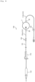
- Fig. 1 shows a filtration device 1 for infusion as an embodiment of the filtration device according to the present disclosure.
- Fig. 1 is a top view of the filtration device 1.
- Figs. 2 and 3 are cross-sectional views of the filtration device 1.
- Fig. 2 is a cross-sectional view of a cross section taken along a line I-I in Fig. 1 .
- Fig. 3 is a cross-sectional view of a cross section taken along a line II-II in Fig. 1 .
- the filtration device 1 includes a housing 2 and a filtration sheet 3.
- a thickness direction of the filtration sheet 3 is simply referred to as a "thickness direction A”.
- a direction orthogonal to the thickness direction of the filtration sheet 3 is simply referred to as a "sheet extending direction B”.
- the housing 2 defines a liquid flow path 2a.
- the filtration sheet 3 separates the liquid flow path 2a into a flow path upstream side and a flow path downstream side.
- the filtration sheet 3 is a filter that removes the foreign matters in the liquid.
- the housing 2 includes a first housing member 11, a second housing member 12, and a joining member 13.
- the first housing member 11 and the second housing member 12 sandwich the filtration sheet 3.
- the joining member 13 joins the first housing member 11 and the second housing member 12 in a state in which the filtration sheet 3 is sandwiched between the first housing member 11 and the second housing member 12.
- the first housing member 11 and the second housing member 12 are not in contact with each other at a position on an outer side relative to an outer edge 3a of the filtration sheet 3 in the sheet extending direction B. That is, although the first housing member 11 and the second housing member 12 sandwich the filtration sheet 3 from both surfaces in the thickness direction A, the first housing member 11 and the second housing member 12 are not in direct contact each other at a position at which the filtration sheet 3 is not interposed between the first housing member 11 and the second housing member 12.
- the joining member 13 seals a gap 60 between the first housing member 11 and the second housing member 12 at the position on the outer side relative to the outer edge 3a of the filtration sheet 3 in the sheet extending direction B. That is, when joining the first housing member 11 and the second housing member 12, the joining member 13 seals the gap 60 between the first housing member 11 and the second housing member 12 at the position on the outer side relative to the outer edge 3a of the filtration sheet 3 in the sheet extending direction B.
- the fixing strength of the filtration sheet 3 can be increased as compared with a configuration in which the first housing member and the second housing member are in direct contact with each other and positioned with each other.
- the first housing member 11 and the second housing member 12 in the state of sandwiching the filtration sheet 3 are joined by the joining member 13 on the outer side relative to the outer edge 3a of the filtration sheet 3 in the sheet extending direction B. Accordingly, a mutual positional relationship between the first housing member 11 and the second housing member 12 can be fixed by the joining member 13 while maintaining the state in which the filtration sheet 3 is sandwiched by the first housing member 11 and the second housing member 12. Accordingly, it is possible to implement the housing 2 capable of increasing the fixing strength of the filtration sheet 3.
- the filtration device 1 of the present embodiment includes a ventilation sheet 4 in addition to the housing 2 and the filtration sheet 3 described above.
- the housing 2 of the present embodiment includes the first housing member 11, the second housing member 12, and the joining member 13.
- the first housing member 11 of the present embodiment includes a top plate portion 21, an annular protruding portion 22 protruding from the top plate portion 21, and an inflow port portion 23 protruding radially outward from the annular protruding portion 22.
- the top plate portion 21 has a substantially circular flat external shape.
- the top plate portion 21 includes a central portion 21b on a radially inner side relative to a position in which the annular protruding portion 22 protrudes, and an outer edge portion 21c on a radially outer side relative to the position in which the annular protruding portion 22 protrudes.
- the top plate portion 21 defines an opening portion 21a through which gas in the liquid flow path 2a can be discharged to the outside.
- the opening portion 21a of the present embodiment is provided in the central portion 21b of the top wall portion 21.
- a lower surface side of the opening portion 21a, which is the liquid flow path 2a side, is covered with the ventilation sheet 4 described later.
- the annular protruding portion 22 protrudes from a lower surface of the top plate portion 21 toward the second housing member 12.
- the filtration sheet 3 of the present embodiment is sandwiched and compressed between a distal end surface of the annular protruding portion 22 and an upper surface of the second housing member 12 to be described later.
- the inflow port portion 23 is a tubular portion protruding radially outward from the annular protruding portion 22, and defines a liquid inflow port 23a inside.
- the liquid inflow port 23a communicates with a flow path upstream side space 11a defined by the central portion 21b of the top plate portion 21 and the protruding portion 22.
- the liquid inflow port 23a and the flow path upstream side space 11a constitute a part of the liquid flow path 2a in the housing 2.
- the second housing member 12 of the present embodiment includes a main body plate portion 31 and an outflow port portion 32 protruding from the main body plate portion 31.
- the main body plate portion 31 has a substantially circular flat external shape.
- the main body plate portion 31 includes a central portion 31b formed with a plurality of ribs 31a on an upper surface of the main body plate portion 31 facing the lower surface of the top plate portion 21 of the first housing member 11, and an outer edge portion 31c formed with no ribs 31a on the upper surface of the main body plate portion 31.
- the ribs 31a formed in the central portion 31b extend substantially linearly. Extending directions of the plurality of ribs 31a are substantially parallel to each other. The plurality of ribs 31a are disposed at predetermined intervals.
- the filtration sheet 3 is supported by top portions of the plurality of ribs 31a. Then, the liquid that has passed through the filtration sheet 3 flows into a groove space as a flow path downstream side space 12a among the plurality of ribs 31a.
- the outer edge portion 31c together with the annular protruding portion 22 of the first housing member 11, constitutes a sandwiching portion that sandwiches the filtration sheet 3.
- the filtration sheet 3 is sandwiched between the distal end surface of the annular protruding portion 22 of the first housing member 11 and an upper surface of the outer edge portion 31c of the main body plate portion 31 of the second housing member 12.
- the upper surface of the outer edge portion 31c is flush with a virtual plane passing through the top portions of the plurality of ribs 31a of the central portion 31b.
- the outflow port portion 32 is a tubular portion protruding in a radially outward side of the main body plate portion 31, and defines a liquid outflow port 32a inside.
- the liquid outflow port 32a communicates with the groove space as the flow path downstream side space 12a described above.
- the liquid outflow port 32a and the flow path downstream space 12a constitute a part of the liquid flow path 2a in the housing 2.
- the liquid flow path 2a in the housing 2 of the present embodiment is constituted by the liquid inflow port 23a, the flow path upstream side space 11a, the flow path downstream side space 12a, and the liquid outflow port 32a.
- the liquid flowing in from the liquid inflow port 23a passes through the filtration sheet 3 from the flow path upstream side space 11a, enters the groove space as the flow path downstream side space 12a, and flows to the outside from the liquid outflow port 32a.
- the joining member 13 of the present embodiment is located in the gap 60 between the first housing member 11 and the second housing member 12, and is joined to the first housing member 11 and the second housing member 12.
- the first housing member 11 and the second housing member 12 are joined by the joining member 13. Accordingly, the gap 60 between the first housing member 11 and the second housing member 12 is sealed from the outside.
- the liquid flow path 2a can be sealed. That is, the joining member 13 according to the present embodiment is disposed in the gap 60, thereby achieving both joining of the first housing member 11 and the second housing member 12 and sealing of the gap 60.
- the joining member 13 according to the present embodiment is interposed between the outer edge portion 21c of the top plate portion 21 of the first housing member 11 and the outer edge portion 31c of the main body plate portion 31 of the second housing member 12. More specifically, the joining member 13 according to the present embodiment is disposed over an entire region in a circumferential direction in an annular groove including the gap 60.
- the annular groove includes the outer edge portion 21c of the top plate portion 21 of the first housing member 11, the annular protruding portion 22 of the first housing member 11, and the outer edge portion 31c of the main body plate portion 31 of the second housing member 12. Accordingly, the gap 60 is sealed by the joining member 13 over the entire region in the circumferential direction.
- the first housing member 11, the second housing member 12, and the joining member 13 are made of a resin material.
- the first housing member 11, the second housing member 12, and the joining member 13 are joined by welding such as fusion.
- the gap 60 is filled with a molding material and solidified, and thereby the joining member 13 capable of achieving both the joining of the first housing member 11 and the second housing member 12 and the sealing of the gap 60 can be molded.
- the first housing member 11 and the second housing member 12 are melted by heat generated by the molding material of the joining member 13 and are fusion-bonded to the joining member 13, and the gap 60 is sealed.
- Examples of the material of the first housing member 11, the second housing member 12, and the joining member 13 include various resin materials such as polyolefins such as polyethylene, polypropylene, and ethylene-propylene copolymer; ethylene-vinyl acetate copolymer (EVA); polyvinyl chloride; polyvinylidene chloride; polystyrene; polyamide; polyimide; polyamideimide; polycarbonate; poly-(4-methylpentene-1); ionomer; acrylic resin; polymethyl methacrylate; acrylonitrile-butadiene-styrene copolymer (ABS resin); acrylonitrile-styrene copolymer (AS resin); butadiene-styrene copolymer; polyesters such as polyethylene terephthalate (PET), polybutylene terephthalate (PBT), and polycyclohexane terephthalate (PCT); polyether; polyether ketone (PEK); poly
- resin materials constituting the first housing member 11, the second housing member 12, and the joining member 13 according to the present embodiment can be appropriately selected from the various resin materials listed above, wherein the material for the first housing, the second housing and the joining member is the same resin material, for instance polycarbonate. In this way, joining strength of the welding of the first housing member 11, the second housing member 12, and the joining member 13 can be increased.
- the joining member 13 joins the first housing member 11 and the second housing member 12 by welding the first housing member 11 with the second housing member 12.
- the configuration thereof is not particularly limited as long as the first housing member 11 and the second housing member 12 are joined and the gap 60 can be sealed.
- the joining member 13 is located in the gap 60 between the first housing member 11 and the second housing member 12, and is joined to the first housing member 11 and the second housing member 12, and thereby the housing 2 can be easily downsized compared with a configuration in which a joining member is provided outside the gap 60.
- the entire joining member 13 according to the present embodiment is disposed in the annular groove including the gap 60, a part of the joint member 13 may protrude from the annular groove.
- the housing 2 includes the first housing member 11, the second housing member 12, and the joining member 13 described above.
- a member other than the above members may be further provided.
- first housing member 11, the second housing member 12, and the joining member 13 are not limited to the shapes described above, and may be different shapes.
- the first housing member 11 defines the liquid inflow port 23a of the liquid flow path 2a.
- the second housing member 12 defines the liquid outflow port 32a of the liquid flow path 2a.
- the first housing member may define the liquid outflow port, and the second housing member may define the liquid inflow port.
- One of the first housing member 11 and the second housing member 12 alone may define the liquid inflow port and the liquid outflow port.
- the first housing member defines one of the liquid inflow port and the fluid outflow port of the liquid flow path
- the second housing member defines the other one of the liquid inflow port and the liquid outflow port of the liquid flow path.
- the first housing member 11 includes the protruding portion 22 that sandwiches the filtration sheet 3, and the second housing member 12 does not include the protruding portion that sandwiches the filtration sheet 3.
- the present disclosure is not limited to the configuration. That is, instead of or in addition to the first housing member 11 including the protruding portion 22, the second housing member 12 may include a protruding portion that sandwiches the filtration sheet 3. Further, both the first housing member 11 and the second housing member 12 may be not include the protruding portion that sandwiches the filtration sheet 3.
- at least one member of the first housing member 11 and the second housing member 12 preferably includes a protruding portion protruding toward the other member. In this way, the filtration sheet 3 can be fixed more firmly. Details of the above will be described later.
- each of the first housing member 11 and the second housing member 12 is formed by one component.
- the present disclosure is not limited to this configuration, and each of the first housing member 11 and the second housing member 12 may be formed by combining two or more components.
- the filtration sheet 3 is a hydrophilic filter having a substantially circular external shape.
- a hydrophilic porous membrane or a hydrophilic nonwoven fabric can be used as the hydrophilic filter as the filtration sheet 3.
- the material of the filtration sheet 3 include hydrophilic materials such as polysulfone, cellulose acetate, and nitrocellulose.
- the filtration sheet 3 may be formed by hydrophilizing a hydrophobic filter made of a hydrophobic material such as polypropylene, polyethylene, polyester, or polytetrafluoroethylene.
- the filtration sheet 3 according to the present embodiment has the substantially circular external shape.
- the filtration sheet 3 according to the present embodiment includes a sandwiched portion 41 sandwiched by the first housing member 11 and the second housing member 12, a liquid passage portion 42 located on a radially inward side of the sandwiched portion 41, and an outer edge portion 43 extending on a radially outward side of the sandwiched portion 41.
- the sandwiched portion 41 according to the present embodiment is a part of the filtration sheet 3, in which the sandwiched portion 41 is in contact with the distal end surface of the annular protruding portion 22 of the first housing member 11 and the upper surface of the outer edge portion 31c of the main body plate portion 31 of the second housing member 12.
- the sandwiched portion 41 is sandwiched between the distal end surface of the annular protruding portion 22 and the upper surface of the outer edge portion 31c. That is, the filtration sheet 3 according to the present embodiment is sandwiched between the first housing member 11 and the second housing member 12 at a position of the protruding portion 22.
- the liquid passage portion 42 is located on an inner side relative to the sandwiched portion 41 in a plan view of the filtration sheet 3 as viewed in the thickness direction A.
- the liquid passage portion 42 is a part that is located in the liquid flow path 2a and removes the foreign matters in the passing liquid.
- the liquid passage portion 42 of the present embodiment is supported by the top portions of the plurality of ribs 31a provided on an upper surface of the central portion 31b of the main body plate portion 31 of the second housing member 12.
- the outer edge portion 43 according to the present embodiment is located on an outer side relative to the sandwiched portion 41 in the plan view of the filtration sheet 3 as viewed in the thickness direction A.
- the first housing member 11 and the second housing member 12 according to the present embodiment do not sandwich the outer edge 3a of the filtration sheet 3 but sandwich the filtration sheet 3 at a position on an inner side relative to the outer edge 3a. Therefore, the filtration sheet 3 according to the present embodiment includes the outer edge portion 43 extending on a radially outer side relative to the sandwiched portion 41.
- the outer edge portion 43 according to the present embodiment is joined to the joining member 13. Specifically, the outer edge portion 43 according to the present embodiment is located between a lower surface of the outer edge portion 21c of the top plate portion 21 of the first housing member 11 and the upper surface of the outer edge portion 31c of the main body plate portion 31 of the second housing member 12. In a plan view in the thickness direction A, the outer edge 3a of the filtration sheet 3 does not protrude outward in the sheet extending direction B beyond an outer edge 21d of the top plate portion 21 of the first housing member 11 and an outer edge 31d of the main body plate portion 31 of the second housing member 12.
- the joining member 13 according to the present embodiment is not only located in the gap 60 on the outer side relative to the outer edge 3a of the filtration sheet 3 in the sheet extending direction B, but a part of the joining member 13 also enters from the gap 60 to the inner side relative to the outer edge 3a of the filtration sheet 3 in the sheet extending direction B. Accordingly, the joining member 13 according to the present embodiment is joined by welding not only to the first housing member 11 and the second housing member 12, but also to the outer edge portion 43 of the filtration sheet 3. In this way, the joining member 13 is joined not only to the first housing member 11 and the second housing member 12, but also to the outer edge portion 43 of the filtration sheet 3, and thereby the filtration sheet 3 can be fixed more firmly.
- the joining member 13 is welded to an upper surface and an outer peripheral end surface of the outer edge portion 43 of the filtration sheet 3 on the first housing member 11 side.
- the welding position is not particularly limited as long as the joining member 13 is welded to at least one of the upper surface, the outer peripheral end surface, and a lower surface of the outer edge portion 43 of the filtration sheet 3.
- the single-layer filtration sheet 3 is sandwiched by the first housing member 11 and the second housing member 12.
- the present disclosure is not limited to this configuration, and for example, a plurality of stacked filtration sheets 3 may be sandwiched by the first housing member 11 and the second housing member 12.
- the ventilation sheet 4 covers the opening portion 21a defined by the first housing member 11.
- the gas in the liquid flow path 2a can be discharged from the ventilation sheet 4.
- the ventilation sheet 4 is attached to the lower surface of the top plate portion 21 of the first housing member 11 on the liquid flow path 2a side in a manner of covering the opening portion 21a.
- the ventilation sheet 4 can be attached to the lower surface of the top plate portion 21 by various methods, for example, welding by heat sealing or the like, or adhesion by an adhesive or the like.
- the ventilation sheet 4 is a hydrophobic filter.
- the ventilation sheet 4 has water impermeability, and allows the gas to flow out from the opening portion 21a and prevents the liquid from flowing out from the opening portion 21a.
- a hydrophobic porous membrane or a hydrophobic nonwoven fabric can be used as the ventilation sheet 4, for example.
- the material of the ventilation sheet 4 include hydrophobic materials such as polypropylene, polyethylene, polysulfone, polyacrylonitrile, polytetrafluoroethylene, and cellulose acetate.
- an infusion set 110 including the filtration device 1 of the present embodiment will be described with reference to Fig. 4 .
- the infusion set 110 can form an infusion line connecting an infusion bag (not shown in Fig. 4 ) to an indwelling needle (also not shown in Fig. 4 ) .
- the infusion set 110 includes a plurality of infusion tubes 111, a drip chamber 112 capable of visually recognizing a flow rate of an infusion agent supplied from the infusion bag, a clamp 113 that adjusts the flow rate of the infusion agent in the infusion tube 111, the filtration device 1, a connector 114 that connects the infusion tubes 111, and a one-touch clamp 115 that blocks the infusion tubes 111.
- the inflow port portion 23 of the filtration device 1 is liquid-tightly connected to a first infusion tube 111a on the flow path upstream side.
- the outflow port portion 32 of the filtration device 1 is liquid-tightly connected to a second infusion tube 111b on the flow path downstream side. Accordingly, the liquid in the infusion bag flows from a hollow portion of the first infusion tube 111a into the liquid flow path 2a of the filtration device 1, is filtered by the filtration sheet 3 (see Figs. 2 and 3 ), flows out to a hollow portion of the second infusion tube 111b, and is sent to the indwelling needle.
- a position of the filtration device 1 in the infusion set 110 is not limited to a position shown in Fig. 4 .
- the filtration device 1 is disposed on the flow path downstream side relative to the connector 114, the filtration device may be disposed on the flow path upstream side relative to the connector 114, for example.
- the infusion set 110 shown in Fig. 4 includes the plurality of infusion tubes 111, the drip chamber cartridge 112, the clamp 113, the filtration device 1, the connector 114, and the one-touch clamp 115.
- a configuration is not limited to the configuration in Fig. 4 as long as the configuration includes at least one infusion tube 111 and the filtration device 1. Therefore, for example, an infusion set that does not include the connector 114 may be used.
- the filtration device according to the present disclosure is not limited to the specific configuration described in the embodiment described above, and various modifications and changes can be made without departing from the scope of the claims.
- the filtration device 1 for infusion has been described in the above embodiment, the filtration device according to the present disclosure can be applied to a filtration device for hemodialysis and a filtration device for removing white blood cells as described above.
- a method for manufacturing the filtration device 1 described above is not particularly limited, and the filtration device 1 can be manufactured using die slide molding, for example.
- the present disclosure relates to a filtration device.
Landscapes
- Health & Medical Sciences (AREA)
- Heart & Thoracic Surgery (AREA)
- Vascular Medicine (AREA)
- Life Sciences & Earth Sciences (AREA)
- General Health & Medical Sciences (AREA)
- Anesthesiology (AREA)
- Biomedical Technology (AREA)
- Hematology (AREA)
- Veterinary Medicine (AREA)
- Animal Behavior & Ethology (AREA)
- Engineering & Computer Science (AREA)
- Public Health (AREA)
- Emergency Medicine (AREA)
- Cardiology (AREA)
- Separation Using Semi-Permeable Membranes (AREA)
- External Artificial Organs (AREA)
- Infusion, Injection, And Reservoir Apparatuses (AREA)
Description
- The present disclosure relates to a filtration device. In particular, the present invention relates to a filtration device according to the preamble of
claim 1, such as it is e.g. known fromEP 0 806 475 A2 . - Currently, various types of medical filtration devices are used to remove foreign matters in a liquid.
PTL 1 describes such a filtration device. The filtration device described inPTL 1 includes a hydrophilic filter as a filtration sheet. -
PTL 2 discloses a blood processing filter as a filtration device. The blood processing filter ofPTL 2 includes an inlet side container member and an outlet side container member. An inlet side joint portion and an outlet side joint portion, which are joined to each other to form a joint portion, are respectively provided on outer edge portions including end surfaces of the inlet side container member and the outlet side container member according toPTL 2. The inlet side container member and the outlet side container member are respectively provided with an inlet side grip portion and an outlet side grip portion at inner edges of the inlet side joint portion and the outlet side joint portion. The inlet side grip portion and the outlet side grip portion grip an outer edge portion of a filter element as a filtration sheet. -
- PTL 1:
JP-B-H1-17383 - PTL 2:
WO-2015-050215 - The hydrophilic filter as the filtration sheet described in
PTL 1 is supported on a housing. On the other hand, the filter element as the filtration sheet described inPTL 2 is gripped by the inlet side grip portion and the outlet side grip portion. Therefore, the filter element described in PTL2 is less likely to be displaced. However, there is still room for improvement in fixing strength of the filtration sheet. - An object of the present disclosure is to provide a filtration device having a configuration capable of fixing a filtration sheet more firmly.
- In order to solve the above problem, the invention provides a filtration device according to
independent claim 1. The dependent claims relate to advantageous embodiments. - In one embodiment of the present disclosure, the joining member is located in the gap between the first housing member and the second housing member, and is joined to the first housing member and the second housing member.
- In one embodiment of the present disclosure, at least one member of the first housing member and the second housing member includes a protruding portion protruding toward the other member, and the filtration sheet is sandwiched between the first housing member and the second housing member at a position of the protruding portion.
- In one embodiment of the present disclosure, the filtration sheet is a hydrophilic filter.
- In one embodiment of the present disclosure, the first housing member defines an opening portion capable of discharging a gas in the liquid flow path, and the filtration device further includes a ventilation sheet that covers the opening portion.
- In one embodiment of the present disclosure, the first housing member defines one of a liquid inflow port and a fluid outflow port of the liquid flow path, and the second housing member defines the other one of the liquid inflow port and the liquid outflow port of the liquid flow path.
- According to the present disclosure, it is possible to provide a filtration device having a configuration capable of fixing a filtration sheet more firmly.
-
- [
Fig. 1] Fig. 1 is a top view of a filtration device according to an embodiment of the present disclosure. - [
Fig. 2] Fig. 2 is a cross-sectional view taken along a line I-I inFig. 1 . - [
Fig. 3] Fig. 3 is a cross-sectional view taken along a line II-II inFig. 1 . - [
Fig. 4] Fig. 4 is a diagram showing an infusion set including the filtration device shown inFig. 1 . - Hereinafter, an embodiment of a filtration device according to the present disclosure will be described as an example with reference to the drawings. In the drawings, common members and portions are denoted by the same reference numerals.
- The filtration device according to the present disclosure can be used as a medical filtration device. Examples of the medical filtration device include a filtration device for infusion, a filtration device for hemodialysis, and a filtration device for removing white blood cells. Hereinafter, in the present embodiment, the filtration device for infusion will be described as an example of the medical filtration device.
-
Fig. 1 shows afiltration device 1 for infusion as an embodiment of the filtration device according to the present disclosure.Fig. 1 is a top view of thefiltration device 1.Figs. 2 and3 are cross-sectional views of thefiltration device 1.Fig. 2 is a cross-sectional view of a cross section taken along a line I-I inFig. 1 .Fig. 3 is a cross-sectional view of a cross section taken along a line II-II inFig. 1 . - As shown in
Figs. 1 to 3 , thefiltration device 1 includes ahousing 2 and a filtration sheet 3. Hereinafter, a thickness direction of the filtration sheet 3 is simply referred to as a "thickness direction A". A direction orthogonal to the thickness direction of the filtration sheet 3 is simply referred to as a "sheet extending direction B". - As shown in
Figs. 2 and3 , thehousing 2 defines aliquid flow path 2a. The filtration sheet 3 separates theliquid flow path 2a into a flow path upstream side and a flow path downstream side. - Foreign matters in a liquid flowing through the
liquid flow path 2a from the flow path upstream side toward the flow path downstream side is removed by passing through the filtration sheet 3. That is, the filtration sheet 3 is a filter that removes the foreign matters in the liquid. - As shown in
Figs. 2 and3 , thehousing 2 includes afirst housing member 11, asecond housing member 12, and a joiningmember 13. Thefirst housing member 11 and thesecond housing member 12 sandwich the filtration sheet 3. The joiningmember 13 joins thefirst housing member 11 and thesecond housing member 12 in a state in which the filtration sheet 3 is sandwiched between thefirst housing member 11 and thesecond housing member 12. - As shown in
Figs. 2 and3 , thefirst housing member 11 and thesecond housing member 12 are not in contact with each other at a position on an outer side relative to anouter edge 3a of the filtration sheet 3 in the sheet extending direction B. That is, although thefirst housing member 11 and thesecond housing member 12 sandwich the filtration sheet 3 from both surfaces in the thickness direction A, thefirst housing member 11 and thesecond housing member 12 are not in direct contact each other at a position at which the filtration sheet 3 is not interposed between thefirst housing member 11 and thesecond housing member 12. - As shown in
Figs. 2 and3 , the joiningmember 13 seals agap 60 between thefirst housing member 11 and thesecond housing member 12 at the position on the outer side relative to theouter edge 3a of the filtration sheet 3 in the sheet extending direction B. That is, when joining thefirst housing member 11 and thesecond housing member 12, the joiningmember 13 seals thegap 60 between thefirst housing member 11 and thesecond housing member 12 at the position on the outer side relative to theouter edge 3a of the filtration sheet 3 in the sheet extending direction B. - As described above, since the filtration sheet 3 is sandwiched between the
first housing member 11 and thesecond housing member 12 which are not in direct contact with each other, the fixing strength of the filtration sheet 3 can be increased as compared with a configuration in which the first housing member and the second housing member are in direct contact with each other and positioned with each other. Thefirst housing member 11 and thesecond housing member 12 in the state of sandwiching the filtration sheet 3 are joined by the joiningmember 13 on the outer side relative to theouter edge 3a of the filtration sheet 3 in the sheet extending direction B. Accordingly, a mutual positional relationship between thefirst housing member 11 and thesecond housing member 12 can be fixed by the joiningmember 13 while maintaining the state in which the filtration sheet 3 is sandwiched by thefirst housing member 11 and thesecond housing member 12. Accordingly, it is possible to implement thehousing 2 capable of increasing the fixing strength of the filtration sheet 3. - Hereinafter, further details of the
filtration device 1 according to the present embodiment will be described with reference toFigs. 1 to 3 . Thefiltration device 1 of the present embodiment includes aventilation sheet 4 in addition to thehousing 2 and the filtration sheet 3 described above. - As described above, the
housing 2 of the present embodiment includes thefirst housing member 11, thesecond housing member 12, and the joiningmember 13. - The
first housing member 11 of the present embodiment includes atop plate portion 21, an annular protrudingportion 22 protruding from thetop plate portion 21, and aninflow port portion 23 protruding radially outward from the annular protrudingportion 22. - The
top plate portion 21 has a substantially circular flat external shape. Thetop plate portion 21 includes acentral portion 21b on a radially inner side relative to a position in which the annular protrudingportion 22 protrudes, and anouter edge portion 21c on a radially outer side relative to the position in which the annular protrudingportion 22 protrudes. - The
top plate portion 21 defines anopening portion 21a through which gas in theliquid flow path 2a can be discharged to the outside. Specifically, theopening portion 21a of the present embodiment is provided in thecentral portion 21b of thetop wall portion 21. A lower surface side of theopening portion 21a, which is theliquid flow path 2a side, is covered with theventilation sheet 4 described later. - The annular protruding
portion 22 protrudes from a lower surface of thetop plate portion 21 toward thesecond housing member 12. As will be described in detail later, the filtration sheet 3 of the present embodiment is sandwiched and compressed between a distal end surface of the annular protrudingportion 22 and an upper surface of thesecond housing member 12 to be described later. - The
inflow port portion 23 is a tubular portion protruding radially outward from the annular protrudingportion 22, and defines aliquid inflow port 23a inside. Theliquid inflow port 23a communicates with a flow pathupstream side space 11a defined by thecentral portion 21b of thetop plate portion 21 and the protrudingportion 22. In other words, theliquid inflow port 23a and the flow pathupstream side space 11a constitute a part of theliquid flow path 2a in thehousing 2. - The
second housing member 12 of the present embodiment includes a mainbody plate portion 31 and anoutflow port portion 32 protruding from the mainbody plate portion 31. - The main
body plate portion 31 has a substantially circular flat external shape. The mainbody plate portion 31 includes acentral portion 31b formed with a plurality ofribs 31a on an upper surface of the mainbody plate portion 31 facing the lower surface of thetop plate portion 21 of thefirst housing member 11, and anouter edge portion 31c formed with noribs 31a on the upper surface of the mainbody plate portion 31. - The
ribs 31a formed in thecentral portion 31b extend substantially linearly. Extending directions of the plurality ofribs 31a are substantially parallel to each other. The plurality ofribs 31a are disposed at predetermined intervals. The filtration sheet 3 is supported by top portions of the plurality ofribs 31a. Then, the liquid that has passed through the filtration sheet 3 flows into a groove space as a flow pathdownstream side space 12a among the plurality ofribs 31a. - The
outer edge portion 31c, together with the annular protrudingportion 22 of thefirst housing member 11, constitutes a sandwiching portion that sandwiches the filtration sheet 3. Specifically, the filtration sheet 3 is sandwiched between the distal end surface of the annular protrudingportion 22 of thefirst housing member 11 and an upper surface of theouter edge portion 31c of the mainbody plate portion 31 of thesecond housing member 12. In the present embodiment, the upper surface of theouter edge portion 31c is flush with a virtual plane passing through the top portions of the plurality ofribs 31a of thecentral portion 31b. - The
outflow port portion 32 is a tubular portion protruding in a radially outward side of the mainbody plate portion 31, and defines aliquid outflow port 32a inside. Theliquid outflow port 32a communicates with the groove space as the flow pathdownstream side space 12a described above. In other words, theliquid outflow port 32a and the flow pathdownstream space 12a constitute a part of theliquid flow path 2a in thehousing 2. - Therefore, the
liquid flow path 2a in thehousing 2 of the present embodiment is constituted by theliquid inflow port 23a, the flow pathupstream side space 11a, the flow pathdownstream side space 12a, and theliquid outflow port 32a. The liquid flowing in from theliquid inflow port 23a passes through the filtration sheet 3 from the flow pathupstream side space 11a, enters the groove space as the flow pathdownstream side space 12a, and flows to the outside from theliquid outflow port 32a. - The joining
member 13 of the present embodiment is located in thegap 60 between thefirst housing member 11 and thesecond housing member 12, and is joined to thefirst housing member 11 and thesecond housing member 12. In other words, thefirst housing member 11 and thesecond housing member 12 are joined by the joiningmember 13. Accordingly, thegap 60 between thefirst housing member 11 and thesecond housing member 12 is sealed from the outside. As a result, theliquid flow path 2a can be sealed. That is, the joiningmember 13 according to the present embodiment is disposed in thegap 60, thereby achieving both joining of thefirst housing member 11 and thesecond housing member 12 and sealing of thegap 60. - Specifically, the joining
member 13 according to the present embodiment is interposed between theouter edge portion 21c of thetop plate portion 21 of thefirst housing member 11 and theouter edge portion 31c of the mainbody plate portion 31 of thesecond housing member 12. More specifically, the joiningmember 13 according to the present embodiment is disposed over an entire region in a circumferential direction in an annular groove including thegap 60. The annular groove includes theouter edge portion 21c of thetop plate portion 21 of thefirst housing member 11, the annular protrudingportion 22 of thefirst housing member 11, and theouter edge portion 31c of the mainbody plate portion 31 of thesecond housing member 12. Accordingly, thegap 60 is sealed by the joiningmember 13 over the entire region in the circumferential direction. - The
first housing member 11, thesecond housing member 12, and the joiningmember 13 according to the present embodiment are made of a resin material. Thefirst housing member 11, thesecond housing member 12, and the joiningmember 13 are joined by welding such as fusion. In this way, after thefirst housing member 11 and thesecond housing member 12 are molded, thegap 60 is filled with a molding material and solidified, and thereby the joiningmember 13 capable of achieving both the joining of thefirst housing member 11 and thesecond housing member 12 and the sealing of thegap 60 can be molded. Specifically, thefirst housing member 11 and thesecond housing member 12 are melted by heat generated by the molding material of the joiningmember 13 and are fusion-bonded to the joiningmember 13, and thegap 60 is sealed. - Examples of the material of the
first housing member 11, thesecond housing member 12, and the joiningmember 13 include various resin materials such as polyolefins such as polyethylene, polypropylene, and ethylene-propylene copolymer; ethylene-vinyl acetate copolymer (EVA); polyvinyl chloride; polyvinylidene chloride; polystyrene; polyamide; polyimide; polyamideimide; polycarbonate; poly-(4-methylpentene-1); ionomer; acrylic resin; polymethyl methacrylate; acrylonitrile-butadiene-styrene copolymer (ABS resin); acrylonitrile-styrene copolymer (AS resin); butadiene-styrene copolymer; polyesters such as polyethylene terephthalate (PET), polybutylene terephthalate (PBT), and polycyclohexane terephthalate (PCT); polyether; polyether ketone (PEK); polyether ether ketone (PEEK); polyether imide; polyacetal (POM); polyphenylene oxide; modified polyphenylene oxide; polysulfone; polyethersulfone; polyphenylene sulfide; polyarylate; aromatic polyester (liquid crystal polymer); polytetrafluoroethylene; polyvinylidene fluoride; and other fluorine-based resins. - Although resin materials constituting the
first housing member 11, thesecond housing member 12, and the joiningmember 13 according to the present embodiment can be appropriately selected from the various resin materials listed above, wherein the material for the first housing, the second housing and the joining member is the same resin material, for instance polycarbonate. In this way, joining strength of the welding of thefirst housing member 11, thesecond housing member 12, and the joiningmember 13 can be increased. - In this way, the joining
member 13 according to the present embodiment joins thefirst housing member 11 and thesecond housing member 12 by welding thefirst housing member 11 with thesecond housing member 12. Alternatively, the configuration thereof is not particularly limited as long as thefirst housing member 11 and thesecond housing member 12 are joined and thegap 60 can be sealed. However, as in the present embodiment, the joiningmember 13 is located in thegap 60 between thefirst housing member 11 and thesecond housing member 12, and is joined to thefirst housing member 11 and thesecond housing member 12, and thereby thehousing 2 can be easily downsized compared with a configuration in which a joining member is provided outside thegap 60. - Although the entire joining
member 13 according to the present embodiment is disposed in the annular groove including thegap 60, a part of thejoint member 13 may protrude from the annular groove. - As described above, the
housing 2 according to the present embodiment includes thefirst housing member 11, thesecond housing member 12, and the joiningmember 13 described above. Alternatively, a member other than the above members may be further provided. - Specific shapes of the
first housing member 11, thesecond housing member 12, and the joiningmember 13 are not limited to the shapes described above, and may be different shapes. For example, in the present embodiment, thefirst housing member 11 defines theliquid inflow port 23a of theliquid flow path 2a. Thesecond housing member 12 defines theliquid outflow port 32a of theliquid flow path 2a. Alternatively, the first housing member may define the liquid outflow port, and the second housing member may define the liquid inflow port. One of thefirst housing member 11 and thesecond housing member 12 alone may define the liquid inflow port and the liquid outflow port. However, when the filtration sheet 3 is sandwiched between thefirst housing member 11 and thesecond housing member 12 as in the present embodiment, it is preferable that the first housing member defines one of the liquid inflow port and the fluid outflow port of the liquid flow path, and the second housing member defines the other one of the liquid inflow port and the liquid outflow port of the liquid flow path. In this way, the configuration of thehousing 2 and the path configuration of theliquid flow path 2a defined by thehousing 2 can be simplified. - Furthermore, in the present embodiment, the
first housing member 11 includes the protrudingportion 22 that sandwiches the filtration sheet 3, and thesecond housing member 12 does not include the protruding portion that sandwiches the filtration sheet 3. Alternatively, the present disclosure is not limited to the configuration. That is, instead of or in addition to thefirst housing member 11 including the protrudingportion 22, thesecond housing member 12 may include a protruding portion that sandwiches the filtration sheet 3. Further, both thefirst housing member 11 and thesecond housing member 12 may be not include the protruding portion that sandwiches the filtration sheet 3. However, as in the present embodiment, at least one member of thefirst housing member 11 and thesecond housing member 12 preferably includes a protruding portion protruding toward the other member. In this way, the filtration sheet 3 can be fixed more firmly. Details of the above will be described later. - Further, in the present embodiment, each of the
first housing member 11 and thesecond housing member 12 is formed by one component. Alternatively, the present disclosure is not limited to this configuration, and each of thefirst housing member 11 and thesecond housing member 12 may be formed by combining two or more components. - The filtration sheet 3 according to the present embodiment is a hydrophilic filter having a substantially circular external shape. As the hydrophilic filter as the filtration sheet 3, for example, a hydrophilic porous membrane or a hydrophilic nonwoven fabric can be used. Examples of the material of the filtration sheet 3 include hydrophilic materials such as polysulfone, cellulose acetate, and nitrocellulose. The filtration sheet 3 may be formed by hydrophilizing a hydrophobic filter made of a hydrophobic material such as polypropylene, polyethylene, polyester, or polytetrafluoroethylene.
- The filtration sheet 3 according to the present embodiment has the substantially circular external shape. The filtration sheet 3 according to the present embodiment includes a sandwiched
portion 41 sandwiched by thefirst housing member 11 and thesecond housing member 12, aliquid passage portion 42 located on a radially inward side of the sandwichedportion 41, and anouter edge portion 43 extending on a radially outward side of the sandwichedportion 41. - The sandwiched
portion 41 according to the present embodiment is a part of the filtration sheet 3, in which the sandwichedportion 41 is in contact with the distal end surface of the annular protrudingportion 22 of thefirst housing member 11 and the upper surface of theouter edge portion 31c of the mainbody plate portion 31 of thesecond housing member 12. The sandwichedportion 41 is sandwiched between the distal end surface of the annular protrudingportion 22 and the upper surface of theouter edge portion 31c. That is, the filtration sheet 3 according to the present embodiment is sandwiched between thefirst housing member 11 and thesecond housing member 12 at a position of the protrudingportion 22. In this way, by sandwiching the filtration sheet 3 at the position of the protrudingportion 22, it is possible to narrow a radial range of the sandwichedportion 41 of the filtration sheet 3. Therefore, a compressive force applied from thefirst housing member 11 and thesecond housing member 12 to the sandwichedportion 41 of the filtration sheet 3 is less likely to be dispersed, and the filtration sheet 3 can be fixed more firmly between thefirst housing member 11 and thesecond housing member 12. - The
liquid passage portion 42 according to the present embodiment is located on an inner side relative to the sandwichedportion 41 in a plan view of the filtration sheet 3 as viewed in the thickness direction A. Theliquid passage portion 42 is a part that is located in theliquid flow path 2a and removes the foreign matters in the passing liquid. Theliquid passage portion 42 of the present embodiment is supported by the top portions of the plurality ofribs 31a provided on an upper surface of thecentral portion 31b of the mainbody plate portion 31 of thesecond housing member 12. The liquid filtered through theliquid passage portion 42 of the filtration sheet 3 from the flow pathupstream side space 11a of theliquid flow path 2a defined by thefirst housing member 11 enters the groove space between the plurality ofribs 31a as the flow pathdownstream side space 12a defined by thesecond housing member 12. - The
outer edge portion 43 according to the present embodiment is located on an outer side relative to the sandwichedportion 41 in the plan view of the filtration sheet 3 as viewed in the thickness direction A. In other words, thefirst housing member 11 and thesecond housing member 12 according to the present embodiment do not sandwich theouter edge 3a of the filtration sheet 3 but sandwich the filtration sheet 3 at a position on an inner side relative to theouter edge 3a. Therefore, the filtration sheet 3 according to the present embodiment includes theouter edge portion 43 extending on a radially outer side relative to the sandwichedportion 41. - The
outer edge portion 43 according to the present embodiment is joined to the joiningmember 13. Specifically, theouter edge portion 43 according to the present embodiment is located between a lower surface of theouter edge portion 21c of thetop plate portion 21 of thefirst housing member 11 and the upper surface of theouter edge portion 31c of the mainbody plate portion 31 of thesecond housing member 12. In a plan view in the thickness direction A, theouter edge 3a of the filtration sheet 3 does not protrude outward in the sheet extending direction B beyond anouter edge 21d of thetop plate portion 21 of thefirst housing member 11 and anouter edge 31d of the mainbody plate portion 31 of thesecond housing member 12. Also, the joiningmember 13 according to the present embodiment is not only located in thegap 60 on the outer side relative to theouter edge 3a of the filtration sheet 3 in the sheet extending direction B, but a part of the joiningmember 13 also enters from thegap 60 to the inner side relative to theouter edge 3a of the filtration sheet 3 in the sheet extending direction B. Accordingly, the joiningmember 13 according to the present embodiment is joined by welding not only to thefirst housing member 11 and thesecond housing member 12, but also to theouter edge portion 43 of the filtration sheet 3. In this way, the joiningmember 13 is joined not only to thefirst housing member 11 and thesecond housing member 12, but also to theouter edge portion 43 of the filtration sheet 3, and thereby the filtration sheet 3 can be fixed more firmly. - As shown in
Figs. 2 and3 , the joiningmember 13 according to the present embodiment is welded to an upper surface and an outer peripheral end surface of theouter edge portion 43 of the filtration sheet 3 on thefirst housing member 11 side. Alternatively, the welding position is not particularly limited as long as the joiningmember 13 is welded to at least one of the upper surface, the outer peripheral end surface, and a lower surface of theouter edge portion 43 of the filtration sheet 3. - In the
filtration device 1 according to the present embodiment, the single-layer filtration sheet 3 is sandwiched by thefirst housing member 11 and thesecond housing member 12. Alternatively, the present disclosure is not limited to this configuration, and for example, a plurality of stacked filtration sheets 3 may be sandwiched by thefirst housing member 11 and thesecond housing member 12. - The
ventilation sheet 4 according to the present embodiment covers theopening portion 21a defined by thefirst housing member 11. The gas in theliquid flow path 2a can be discharged from theventilation sheet 4. More specifically, theventilation sheet 4 is attached to the lower surface of thetop plate portion 21 of thefirst housing member 11 on theliquid flow path 2a side in a manner of covering theopening portion 21a. Theventilation sheet 4 can be attached to the lower surface of thetop plate portion 21 by various methods, for example, welding by heat sealing or the like, or adhesion by an adhesive or the like. - The
ventilation sheet 4 is a hydrophobic filter. Theventilation sheet 4 has water impermeability, and allows the gas to flow out from theopening portion 21a and prevents the liquid from flowing out from theopening portion 21a. As theventilation sheet 4, for example, a hydrophobic porous membrane or a hydrophobic nonwoven fabric can be used. Examples of the material of theventilation sheet 4 include hydrophobic materials such as polypropylene, polyethylene, polysulfone, polyacrylonitrile, polytetrafluoroethylene, and cellulose acetate. - Next, an infusion set 110 including the
filtration device 1 of the present embodiment will be described with reference toFig. 4 . - The infusion set 110 can form an infusion line connecting an infusion bag (not shown in
Fig. 4 ) to an indwelling needle (also not shown inFig. 4 ) . Specifically, the infusion set 110 includes a plurality ofinfusion tubes 111, adrip chamber 112 capable of visually recognizing a flow rate of an infusion agent supplied from the infusion bag, aclamp 113 that adjusts the flow rate of the infusion agent in theinfusion tube 111, thefiltration device 1, aconnector 114 that connects theinfusion tubes 111, and a one-touch clamp 115 that blocks theinfusion tubes 111. - In the infusion set 110 shown in
Fig. 4 , theinflow port portion 23 of thefiltration device 1 is liquid-tightly connected to afirst infusion tube 111a on the flow path upstream side. Theoutflow port portion 32 of thefiltration device 1 is liquid-tightly connected to asecond infusion tube 111b on the flow path downstream side. Accordingly, the liquid in the infusion bag flows from a hollow portion of thefirst infusion tube 111a into theliquid flow path 2a of thefiltration device 1, is filtered by the filtration sheet 3 (seeFigs. 2 and3 ), flows out to a hollow portion of thesecond infusion tube 111b, and is sent to the indwelling needle. - A position of the
filtration device 1 in the infusion set 110 is not limited to a position shown inFig. 4 . Although inFig. 4 , thefiltration device 1 is disposed on the flow path downstream side relative to theconnector 114, the filtration device may be disposed on the flow path upstream side relative to theconnector 114, for example. - The infusion set 110 shown in
Fig. 4 includes the plurality ofinfusion tubes 111, thedrip chamber cartridge 112, theclamp 113, thefiltration device 1, theconnector 114, and the one-touch clamp 115. Alternatively, a configuration is not limited to the configuration inFig. 4 as long as the configuration includes at least oneinfusion tube 111 and thefiltration device 1. Therefore, for example, an infusion set that does not include theconnector 114 may be used. - The filtration device according to the present disclosure is not limited to the specific configuration described in the embodiment described above, and various modifications and changes can be made without departing from the scope of the claims. Although the
filtration device 1 for infusion has been described in the above embodiment, the filtration device according to the present disclosure can be applied to a filtration device for hemodialysis and a filtration device for removing white blood cells as described above. A method for manufacturing thefiltration device 1 described above is not particularly limited, and thefiltration device 1 can be manufactured using die slide molding, for example. - The present disclosure relates to a filtration device.
-
- 1: filtration device
- 2: housing
- 2a: liquid flow path
- 3: filtration sheet
- 3a: outer edge of filtration sheet
- 4: ventilation sheet
- 11: first housing member
- 11a: flow path upstream side space
- 12: second housing member
- 12a: flow path downstream side space
- 13: joining member
- 21: top wall portion
- 21a: opening portion
- 21b: central portion
- 21c: outer edge portion
- 21d: outer edge
- 22: protruding portion
- 23: inflow port portion
- 23a: liquid inflow port
- 31: main body plate portion
- 31a: rib
- 31b: central portion
- 31c: outer edge portion
- 31d: outer edge
- 32: outflow port portion
- 32a: liquid outflow port
- 41: sandwiched portion
- 42: liquid passage portion
- 43: outer edge portion
- 60: gap
- 110: infusion set
- 111: infusion tube
- 111a: first infusion tube
- 111b: second infusion tube
- 112: drip chamber
- 113: clamp
- 114: connector
- 115: one-touch clamp
- A: thickness direction of filtration sheet
- B: sheet extending direction of filtration sheet
Claims (6)
- A filtration device (1) comprising:a housing (2) that defines a liquid flow path (2a); anda filtration sheet (3) that separates the liquid flow path (2a) into a flow path upstream side and a flow path downstream side, whereinthe housing (2) includesa first housing member (11) and a second housing member (12) that sandwich the filtration sheet (3), anda joining member (13) that joins the first housing member (11) and the second housing member (12) in a state in which the filtration sheet (3) is sandwiched between the first housing member (11) and the second housing member (12),the first housing member (11) and the second housing member (12) are not in contact with each other at a position on an outer side relative to an outer edge (21d, 31d) of the filtration sheet (3), andthe joining member (13) seals a gap (60) between the first housing member (11) and the second housing member (12) at the position on the outer side relative to the outer edge (2Id, 31d) of the filtration sheet (3),characterized in thatthe filtration sheet (3) includes an outer edge portion (43) located on an outer side relative to a sandwiched portion (41) sandwiched by the first housing member (11) and the second housing member (12) in a plan view in a thickness direction,the joining member (13) is joined to the outer edge portion (43) of the filtration sheet (3), andthe material for the first housing (11), the second housing (12) and the joining member (13) is the same resin material.
- The filtration device (1) according to claim 1, wherein
the joining member (13) is located in the gap (60) between the first housing member (11) and the second housing member (12), and is joined to the first housing member (11) and the second housing member (12). - The filtration device (1) according to any one of claims 1 to 2, whereinat least one member of the first housing member (11) and the second housing member (12) includes a protruding portion (22) protruding toward the other member, andthe filtration sheet (3) is sandwiched between the first housing member (11) and the second housing member (12) at a position of the protruding portion (22).
- The filtration device (1) according to any one of claims 1 to 3, wherein
the filtration sheet (3) is a hydrophilic filter. - The filtration device (1) according to any one of claims 1 to 4, whereinthe first housing member (11) defines an opening portion (21a) capable of discharging a gas in the liquid flow path (2a), andthe filtration device (1) further comprises a ventilation sheet (4) that covers the opening portion (21a).
- The filtration device (1) according to any one of claims 1 to 5 whereinthe first housing member (11) defines one of a liquid inflow port (23a) and a fluid outflow port (32a) of the liquid flow path (2a), andthe second housing member (12) defines the other one of the liquid inflow port (23a) and the liquid outflow port (32a) of the liquid flow path (2a).
Applications Claiming Priority (2)
| Application Number | Priority Date | Filing Date | Title |
|---|---|---|---|
| JP2019045139 | 2019-03-12 | ||
| PCT/JP2020/002943 WO2020183951A1 (en) | 2019-03-12 | 2020-01-28 | Filtration device |
Publications (3)
| Publication Number | Publication Date |
|---|---|
| EP3906986A1 EP3906986A1 (en) | 2021-11-10 |
| EP3906986A4 EP3906986A4 (en) | 2022-03-16 |
| EP3906986B1 true EP3906986B1 (en) | 2023-05-10 |
Family
ID=72427244
Family Applications (1)
| Application Number | Title | Priority Date | Filing Date |
|---|---|---|---|
| EP20770356.2A Active EP3906986B1 (en) | 2019-03-12 | 2020-01-28 | Filtration device |
Country Status (5)
| Country | Link |
|---|---|
| US (1) | US20210402086A1 (en) |
| EP (1) | EP3906986B1 (en) |
| JP (1) | JP7314251B2 (en) |
| CN (1) | CN112969518A (en) |
| WO (1) | WO2020183951A1 (en) |
Family Cites Families (21)
| Publication number | Priority date | Publication date | Assignee | Title |
|---|---|---|---|---|
| IL51209A (en) * | 1976-03-25 | 1981-02-27 | Baxter Travenol Lab | Blood filter |
| JPS53165796U (en) * | 1977-06-01 | 1978-12-26 | ||
| US4422939A (en) * | 1979-11-07 | 1983-12-27 | Texas Medical Products, Inc. | Blood and perfusate filter |
| JPS5967966A (en) * | 1982-10-13 | 1984-04-17 | テルモ株式会社 | Infusion liquid filter |
| JPS5971761A (en) | 1982-10-18 | 1984-04-23 | テルモ株式会社 | Infusion liquid filter |
| JPS60193468A (en) * | 1984-03-15 | 1985-10-01 | 旭メデイカル株式会社 | Leucocyte removal filter |
| JPS60194959A (en) * | 1984-03-19 | 1985-10-03 | 旭メデイカル株式会社 | Modified blood component removing filter |
| DE3801866A1 (en) * | 1988-01-22 | 1989-08-03 | Schleicher & Schuell Gmbh | DISPOSABLE FILTER HOLDER WITH DOUBLE-SIDED FILTER SUPPORT |
| JP3311091B2 (en) * | 1993-06-27 | 2002-08-05 | テルモ株式会社 | Filter for separating white blood cells and filter for separating white blood cells and platelets |
| US5707520A (en) * | 1993-06-27 | 1998-01-13 | Terumo Kabushiki Kaisha | Remover unit for use in filtration circuit for removing at least leukocyte |
| US5798041A (en) * | 1995-09-06 | 1998-08-25 | Hemasure, Inc. | In-line liquid filtration device useable for blood, blood products or the like |
| US5601713A (en) * | 1994-12-06 | 1997-02-11 | Nupro Company | Filter systems and apparatus |
| JP3322595B2 (en) * | 1996-03-28 | 2002-09-09 | テルモ株式会社 | Filter device and method for separating / collecting biological microstructure |
| DE102005052486A1 (en) * | 2005-11-03 | 2007-05-10 | Asana Ro-Wasserbehandlung Gmbh | Water filter housing cap closure has connection holes with smooth sidewalls for matching push-fit connectors |
| DE102011120646B4 (en) * | 2011-12-09 | 2018-11-08 | Mann+Hummel Gmbh | Liquid filter and filter element with drain valve of a liquid filter |
| US9421354B2 (en) * | 2013-01-02 | 2016-08-23 | Illinois Tool Works Inc. | Check valve with integrated filter |
| WO2017141948A1 (en) * | 2016-02-16 | 2017-08-24 | テルモ株式会社 | Blood treatment filter, production method thereof, and blood bag system |
| CN206534951U (en) * | 2016-08-29 | 2017-10-03 | 上海振浦医疗设备有限公司 | A kind of novel double-layer is molded lucifuge liquid medicine filter |
| JP6957086B2 (en) * | 2017-03-28 | 2021-11-02 | テルモ株式会社 | Medical filter |
| CN207462404U (en) * | 2017-04-01 | 2018-06-08 | 胡敏 | A kind of medical treatment and nursing liquid medicine filter and liquid infusion apparatus |
| CN207856029U (en) * | 2017-10-30 | 2018-09-14 | 陈丹军 | A kind of free bonding, no-welding filter for infusion |
-
2020
- 2020-01-28 WO PCT/JP2020/002943 patent/WO2020183951A1/en unknown
- 2020-01-28 JP JP2021505575A patent/JP7314251B2/en active Active
- 2020-01-28 EP EP20770356.2A patent/EP3906986B1/en active Active
- 2020-01-28 CN CN202080006078.8A patent/CN112969518A/en active Pending
-
2021
- 2021-09-09 US US17/471,065 patent/US20210402086A1/en active Pending
Also Published As
| Publication number | Publication date |
|---|---|
| JPWO2020183951A1 (en) | 2020-09-17 |
| JP7314251B2 (en) | 2023-07-25 |
| CN112969518A (en) | 2021-06-15 |
| US20210402086A1 (en) | 2021-12-30 |
| EP3906986A1 (en) | 2021-11-10 |
| WO2020183951A1 (en) | 2020-09-17 |
| EP3906986A4 (en) | 2022-03-16 |
Similar Documents
| Publication | Publication Date | Title |
|---|---|---|
| AU725080B2 (en) | Multiple element filter | |
| US3815754A (en) | Box filter | |
| JP4897086B2 (en) | Filtration device | |
| US8337701B2 (en) | Intravenous filter | |
| US8857627B2 (en) | Blood processing filter | |
| EP3033158B1 (en) | Filter element for biopharmaceutical applications | |
| JPS5973019A (en) | Packed spiral multi-layer filter assembly | |
| EP3906986B1 (en) | Filtration device | |
| JP6559265B2 (en) | Blood treatment filter | |
| JPH08192006A (en) | Filter | |
| JPS5831205B2 (en) | Ekitaioyobi Kitairokasouchi | |
| JP4963053B2 (en) | Joint for extracorporeal circulation module and medical adapter using the joint | |
| JPH11347378A (en) | Spiral membrane element and membrane module using the same | |
| US11298448B2 (en) | Filter unit for whole blood and blood derivatives | |
| JP3834523B2 (en) | Connector type inline filter | |
| JP7172241B2 (en) | water purification cartridge | |
| JP7311092B2 (en) | Tangential flow filtration system and tangential flow filtration cassette | |
| TW201927351A (en) | End cover of dialyzer and fabricating method thereof, and dialyzer | |
| JP2019051463A (en) | Water collection structure | |
| JP5023095B2 (en) | Water purification cartridge | |
| US20140374338A1 (en) | Biological fluid filters with port for optimized flow distribution | |
| JP2000342680A (en) | White blood corpuscle remover | |
| JPH10165779A (en) | Filter membrane module |
Legal Events
| Date | Code | Title | Description |
|---|---|---|---|
| STAA | Information on the status of an ep patent application or granted ep patent |
Free format text: STATUS: THE INTERNATIONAL PUBLICATION HAS BEEN MADE |
|
| PUAI | Public reference made under article 153(3) epc to a published international application that has entered the european phase |
Free format text: ORIGINAL CODE: 0009012 |
|
| STAA | Information on the status of an ep patent application or granted ep patent |
Free format text: STATUS: REQUEST FOR EXAMINATION WAS MADE |
|
| 17P | Request for examination filed |
Effective date: 20210804 |
|
| AK | Designated contracting states |
Kind code of ref document: A1 Designated state(s): AL AT BE BG CH CY CZ DE DK EE ES FI FR GB GR HR HU IE IS IT LI LT LU LV MC MK MT NL NO PL PT RO RS SE SI SK SM TR |
|
| A4 | Supplementary search report drawn up and despatched |
Effective date: 20220216 |
|
| RIC1 | Information provided on ipc code assigned before grant |
Ipc: A61M 1/36 20060101ALI20220210BHEP Ipc: A61M 5/38 20060101ALI20220210BHEP Ipc: A61M 5/165 20060101ALI20220210BHEP Ipc: B01D 29/88 20060101ALI20220210BHEP Ipc: B01D 24/38 20060101ALI20220210BHEP Ipc: B01D 29/00 20060101AFI20220210BHEP |
|
| DAV | Request for validation of the european patent (deleted) | ||
| DAX | Request for extension of the european patent (deleted) | ||
| GRAP | Despatch of communication of intention to grant a patent |
Free format text: ORIGINAL CODE: EPIDOSNIGR1 |
|
| STAA | Information on the status of an ep patent application or granted ep patent |
Free format text: STATUS: GRANT OF PATENT IS INTENDED |
|
| RIC1 | Information provided on ipc code assigned before grant |
Ipc: A61M 1/36 20060101ALI20230210BHEP Ipc: A61M 5/38 20060101ALI20230210BHEP Ipc: A61M 5/165 20060101ALI20230210BHEP Ipc: B01D 29/88 20060101ALI20230210BHEP Ipc: B01D 24/38 20060101ALI20230210BHEP Ipc: B01D 29/00 20060101AFI20230210BHEP |
|
| GRAS | Grant fee paid |
Free format text: ORIGINAL CODE: EPIDOSNIGR3 |
|
| INTG | Intention to grant announced |
Effective date: 20230301 |
|
| RAP3 | Party data changed (applicant data changed or rights of an application transferred) |
Owner name: TERUMO KABUSHIKI KAISHA |
|
| RIN1 | Information on inventor provided before grant (corrected) |
Inventor name: TOYAMA, TAKESHI Inventor name: JOKAJI, MITSURU |
|
| GRAA | (expected) grant |
Free format text: ORIGINAL CODE: 0009210 |
|
| STAA | Information on the status of an ep patent application or granted ep patent |
Free format text: STATUS: THE PATENT HAS BEEN GRANTED |
|
| AK | Designated contracting states |
Kind code of ref document: B1 Designated state(s): AL AT BE BG CH CY CZ DE DK EE ES FI FR GB GR HR HU IE IS IT LI LT LU LV MC MK MT NL NO PL PT RO RS SE SI SK SM TR |
|
| REG | Reference to a national code |
Ref country code: GB Ref legal event code: FG4D |
|
| REG | Reference to a national code |
Ref country code: AT Ref legal event code: REF Ref document number: 1566145 Country of ref document: AT Kind code of ref document: T Effective date: 20230515 Ref country code: CH Ref legal event code: EP |
|
| REG | Reference to a national code |
Ref country code: DE Ref legal event code: R096 Ref document number: 602020010814 Country of ref document: DE |
|
| REG | Reference to a national code |
Ref country code: IE Ref legal event code: FG4D |
|
| REG | Reference to a national code |
Ref country code: LT Ref legal event code: MG9D |
|
| REG | Reference to a national code |
Ref country code: NL Ref legal event code: MP Effective date: 20230510 |
|
| REG | Reference to a national code |
Ref country code: AT Ref legal event code: MK05 Ref document number: 1566145 Country of ref document: AT Kind code of ref document: T Effective date: 20230510 |
|
| PG25 | Lapsed in a contracting state [announced via postgrant information from national office to epo] |
Ref country code: SE Free format text: LAPSE BECAUSE OF FAILURE TO SUBMIT A TRANSLATION OF THE DESCRIPTION OR TO PAY THE FEE WITHIN THE PRESCRIBED TIME-LIMIT Effective date: 20230510 Ref country code: PT Free format text: LAPSE BECAUSE OF FAILURE TO SUBMIT A TRANSLATION OF THE DESCRIPTION OR TO PAY THE FEE WITHIN THE PRESCRIBED TIME-LIMIT Effective date: 20230911 Ref country code: NO Free format text: LAPSE BECAUSE OF FAILURE TO SUBMIT A TRANSLATION OF THE DESCRIPTION OR TO PAY THE FEE WITHIN THE PRESCRIBED TIME-LIMIT Effective date: 20230810 Ref country code: NL Free format text: LAPSE BECAUSE OF FAILURE TO SUBMIT A TRANSLATION OF THE DESCRIPTION OR TO PAY THE FEE WITHIN THE PRESCRIBED TIME-LIMIT Effective date: 20230510 Ref country code: ES Free format text: LAPSE BECAUSE OF FAILURE TO SUBMIT A TRANSLATION OF THE DESCRIPTION OR TO PAY THE FEE WITHIN THE PRESCRIBED TIME-LIMIT Effective date: 20230510 Ref country code: AT Free format text: LAPSE BECAUSE OF FAILURE TO SUBMIT A TRANSLATION OF THE DESCRIPTION OR TO PAY THE FEE WITHIN THE PRESCRIBED TIME-LIMIT Effective date: 20230510 |
|
| PG25 | Lapsed in a contracting state [announced via postgrant information from national office to epo] |
Ref country code: RS Free format text: LAPSE BECAUSE OF FAILURE TO SUBMIT A TRANSLATION OF THE DESCRIPTION OR TO PAY THE FEE WITHIN THE PRESCRIBED TIME-LIMIT Effective date: 20230510 Ref country code: PL Free format text: LAPSE BECAUSE OF FAILURE TO SUBMIT A TRANSLATION OF THE DESCRIPTION OR TO PAY THE FEE WITHIN THE PRESCRIBED TIME-LIMIT Effective date: 20230510 Ref country code: LV Free format text: LAPSE BECAUSE OF FAILURE TO SUBMIT A TRANSLATION OF THE DESCRIPTION OR TO PAY THE FEE WITHIN THE PRESCRIBED TIME-LIMIT Effective date: 20230510 Ref country code: LT Free format text: LAPSE BECAUSE OF FAILURE TO SUBMIT A TRANSLATION OF THE DESCRIPTION OR TO PAY THE FEE WITHIN THE PRESCRIBED TIME-LIMIT Effective date: 20230510 Ref country code: IS Free format text: LAPSE BECAUSE OF FAILURE TO SUBMIT A TRANSLATION OF THE DESCRIPTION OR TO PAY THE FEE WITHIN THE PRESCRIBED TIME-LIMIT Effective date: 20230910 Ref country code: HR Free format text: LAPSE BECAUSE OF FAILURE TO SUBMIT A TRANSLATION OF THE DESCRIPTION OR TO PAY THE FEE WITHIN THE PRESCRIBED TIME-LIMIT Effective date: 20230510 Ref country code: GR Free format text: LAPSE BECAUSE OF FAILURE TO SUBMIT A TRANSLATION OF THE DESCRIPTION OR TO PAY THE FEE WITHIN THE PRESCRIBED TIME-LIMIT Effective date: 20230811 |
|
| PG25 | Lapsed in a contracting state [announced via postgrant information from national office to epo] |
Ref country code: FI Free format text: LAPSE BECAUSE OF FAILURE TO SUBMIT A TRANSLATION OF THE DESCRIPTION OR TO PAY THE FEE WITHIN THE PRESCRIBED TIME-LIMIT Effective date: 20230510 |
|
| PG25 | Lapsed in a contracting state [announced via postgrant information from national office to epo] |
Ref country code: SK Free format text: LAPSE BECAUSE OF FAILURE TO SUBMIT A TRANSLATION OF THE DESCRIPTION OR TO PAY THE FEE WITHIN THE PRESCRIBED TIME-LIMIT Effective date: 20230510 |
|
| PGFP | Annual fee paid to national office [announced via postgrant information from national office to epo] |
Ref country code: GB Payment date: 20231207 Year of fee payment: 5 |
|
| PG25 | Lapsed in a contracting state [announced via postgrant information from national office to epo] |
Ref country code: SM Free format text: LAPSE BECAUSE OF FAILURE TO SUBMIT A TRANSLATION OF THE DESCRIPTION OR TO PAY THE FEE WITHIN THE PRESCRIBED TIME-LIMIT Effective date: 20230510 Ref country code: SK Free format text: LAPSE BECAUSE OF FAILURE TO SUBMIT A TRANSLATION OF THE DESCRIPTION OR TO PAY THE FEE WITHIN THE PRESCRIBED TIME-LIMIT Effective date: 20230510 Ref country code: RO Free format text: LAPSE BECAUSE OF FAILURE TO SUBMIT A TRANSLATION OF THE DESCRIPTION OR TO PAY THE FEE WITHIN THE PRESCRIBED TIME-LIMIT Effective date: 20230510 Ref country code: EE Free format text: LAPSE BECAUSE OF FAILURE TO SUBMIT A TRANSLATION OF THE DESCRIPTION OR TO PAY THE FEE WITHIN THE PRESCRIBED TIME-LIMIT Effective date: 20230510 Ref country code: DK Free format text: LAPSE BECAUSE OF FAILURE TO SUBMIT A TRANSLATION OF THE DESCRIPTION OR TO PAY THE FEE WITHIN THE PRESCRIBED TIME-LIMIT Effective date: 20230510 Ref country code: CZ Free format text: LAPSE BECAUSE OF FAILURE TO SUBMIT A TRANSLATION OF THE DESCRIPTION OR TO PAY THE FEE WITHIN THE PRESCRIBED TIME-LIMIT Effective date: 20230510 |
|
| PGFP | Annual fee paid to national office [announced via postgrant information from national office to epo] |
Ref country code: FR Payment date: 20231212 Year of fee payment: 5 |
|
| REG | Reference to a national code |
Ref country code: DE Ref legal event code: R097 Ref document number: 602020010814 Country of ref document: DE |
|
| PLBE | No opposition filed within time limit |
Free format text: ORIGINAL CODE: 0009261 |
|
| STAA | Information on the status of an ep patent application or granted ep patent |
Free format text: STATUS: NO OPPOSITION FILED WITHIN TIME LIMIT |
|
| 26N | No opposition filed |
Effective date: 20240213 |
|
| PGFP | Annual fee paid to national office [announced via postgrant information from national office to epo] |
Ref country code: DE Payment date: 20231205 Year of fee payment: 5 |
|
| PG25 | Lapsed in a contracting state [announced via postgrant information from national office to epo] |
Ref country code: SI Free format text: LAPSE BECAUSE OF FAILURE TO SUBMIT A TRANSLATION OF THE DESCRIPTION OR TO PAY THE FEE WITHIN THE PRESCRIBED TIME-LIMIT Effective date: 20230510 |
|
| PG25 | Lapsed in a contracting state [announced via postgrant information from national office to epo] |
Ref country code: SI Free format text: LAPSE BECAUSE OF FAILURE TO SUBMIT A TRANSLATION OF THE DESCRIPTION OR TO PAY THE FEE WITHIN THE PRESCRIBED TIME-LIMIT Effective date: 20230510 Ref country code: IT Free format text: LAPSE BECAUSE OF FAILURE TO SUBMIT A TRANSLATION OF THE DESCRIPTION OR TO PAY THE FEE WITHIN THE PRESCRIBED TIME-LIMIT Effective date: 20230510 |
|
| PG25 | Lapsed in a contracting state [announced via postgrant information from national office to epo] |
Ref country code: MC Free format text: LAPSE BECAUSE OF FAILURE TO SUBMIT A TRANSLATION OF THE DESCRIPTION OR TO PAY THE FEE WITHIN THE PRESCRIBED TIME-LIMIT Effective date: 20230510 |
|
| PG25 | Lapsed in a contracting state [announced via postgrant information from national office to epo] |
Ref country code: MC Free format text: LAPSE BECAUSE OF FAILURE TO SUBMIT A TRANSLATION OF THE DESCRIPTION OR TO PAY THE FEE WITHIN THE PRESCRIBED TIME-LIMIT Effective date: 20230510 |
|
| REG | Reference to a national code |
Ref country code: CH Ref legal event code: PL |
|
| PG25 | Lapsed in a contracting state [announced via postgrant information from national office to epo] |
Ref country code: LU Free format text: LAPSE BECAUSE OF NON-PAYMENT OF DUE FEES Effective date: 20240128 |
|
| PG25 | Lapsed in a contracting state [announced via postgrant information from national office to epo] |
Ref country code: LU Free format text: LAPSE BECAUSE OF NON-PAYMENT OF DUE FEES Effective date: 20240128 |