WO2020183789A1 - 動力伝達装置 - Google Patents
動力伝達装置 Download PDFInfo
- Publication number
- WO2020183789A1 WO2020183789A1 PCT/JP2019/044225 JP2019044225W WO2020183789A1 WO 2020183789 A1 WO2020183789 A1 WO 2020183789A1 JP 2019044225 W JP2019044225 W JP 2019044225W WO 2020183789 A1 WO2020183789 A1 WO 2020183789A1
- Authority
- WO
- WIPO (PCT)
- Prior art keywords
- motor
- gear
- shaft
- power transmission
- transmission device
- Prior art date
- Legal status (The legal status is an assumption and is not a legal conclusion. Google has not performed a legal analysis and makes no representation as to the accuracy of the status listed.)
- Ceased
Links
Images






Classifications
-
- B—PERFORMING OPERATIONS; TRANSPORTING
- B60—VEHICLES IN GENERAL
- B60L—PROPULSION OF ELECTRICALLY-PROPELLED VEHICLES; SUPPLYING ELECTRIC POWER FOR AUXILIARY EQUIPMENT OF ELECTRICALLY-PROPELLED VEHICLES; ELECTRODYNAMIC BRAKE SYSTEMS FOR VEHICLES IN GENERAL; MAGNETIC SUSPENSION OR LEVITATION FOR VEHICLES; MONITORING OPERATING VARIABLES OF ELECTRICALLY-PROPELLED VEHICLES; ELECTRIC SAFETY DEVICES FOR ELECTRICALLY-PROPELLED VEHICLES
- B60L15/00—Methods, circuits, or devices for controlling the traction-motor speed of electrically-propelled vehicles
-
- B—PERFORMING OPERATIONS; TRANSPORTING
- B60—VEHICLES IN GENERAL
- B60T—VEHICLE BRAKE CONTROL SYSTEMS OR PARTS THEREOF; BRAKE CONTROL SYSTEMS OR PARTS THEREOF, IN GENERAL; ARRANGEMENT OF BRAKING ELEMENTS ON VEHICLES IN GENERAL; PORTABLE DEVICES FOR PREVENTING UNWANTED MOVEMENT OF VEHICLES; VEHICLE MODIFICATIONS TO FACILITATE COOLING OF BRAKES
- B60T1/00—Arrangements of braking elements, i.e. of those parts where braking effect occurs specially for vehicles
- B60T1/02—Arrangements of braking elements, i.e. of those parts where braking effect occurs specially for vehicles acting by retarding wheels
- B60T1/06—Arrangements of braking elements, i.e. of those parts where braking effect occurs specially for vehicles acting by retarding wheels acting otherwise than on tread, e.g. employing rim, drum, disc, or transmission or on double wheels
-
- B—PERFORMING OPERATIONS; TRANSPORTING
- B60—VEHICLES IN GENERAL
- B60T—VEHICLE BRAKE CONTROL SYSTEMS OR PARTS THEREOF; BRAKE CONTROL SYSTEMS OR PARTS THEREOF, IN GENERAL; ARRANGEMENT OF BRAKING ELEMENTS ON VEHICLES IN GENERAL; PORTABLE DEVICES FOR PREVENTING UNWANTED MOVEMENT OF VEHICLES; VEHICLE MODIFICATIONS TO FACILITATE COOLING OF BRAKES
- B60T7/00—Brake-action initiating means
- B60T7/12—Brake-action initiating means for automatic initiation; for initiation not subject to will of driver or passenger
-
- F—MECHANICAL ENGINEERING; LIGHTING; HEATING; WEAPONS; BLASTING
- F16—ENGINEERING ELEMENTS AND UNITS; GENERAL MEASURES FOR PRODUCING AND MAINTAINING EFFECTIVE FUNCTIONING OF MACHINES OR INSTALLATIONS; THERMAL INSULATION IN GENERAL
- F16D—COUPLINGS FOR TRANSMITTING ROTATION; CLUTCHES; BRAKES
- F16D11/00—Clutches in which the members have interengaging parts
- F16D11/02—Clutches in which the members have interengaging parts disengaged by a contact of a part mounted on the clutch with a stationarily-mounted member
- F16D11/06—Clutches in which the members have interengaging parts disengaged by a contact of a part mounted on the clutch with a stationarily-mounted member with clutching members movable otherwise than only axially, e.g. rotatable keys
-
- F—MECHANICAL ENGINEERING; LIGHTING; HEATING; WEAPONS; BLASTING
- F16—ENGINEERING ELEMENTS AND UNITS; GENERAL MEASURES FOR PRODUCING AND MAINTAINING EFFECTIVE FUNCTIONING OF MACHINES OR INSTALLATIONS; THERMAL INSULATION IN GENERAL
- F16D—COUPLINGS FOR TRANSMITTING ROTATION; CLUTCHES; BRAKES
- F16D23/00—Details of mechanically-actuated clutches not specific for one distinct type
- F16D23/12—Mechanical clutch-actuating mechanisms arranged outside the clutch as such
-
- F—MECHANICAL ENGINEERING; LIGHTING; HEATING; WEAPONS; BLASTING
- F16—ENGINEERING ELEMENTS AND UNITS; GENERAL MEASURES FOR PRODUCING AND MAINTAINING EFFECTIVE FUNCTIONING OF MACHINES OR INSTALLATIONS; THERMAL INSULATION IN GENERAL
- F16H—GEARING
- F16H3/00—Toothed gearings for conveying rotary motion with variable gear ratio or for reversing rotary motion
- F16H3/44—Toothed gearings for conveying rotary motion with variable gear ratio or for reversing rotary motion using gears having orbital motion
- F16H3/46—Gearings having only two central gears, connected by orbital gears
- F16H3/48—Gearings having only two central gears, connected by orbital gears with single orbital gears or pairs of rigidly-connected orbital gears
-
- F—MECHANICAL ENGINEERING; LIGHTING; HEATING; WEAPONS; BLASTING
- F16—ENGINEERING ELEMENTS AND UNITS; GENERAL MEASURES FOR PRODUCING AND MAINTAINING EFFECTIVE FUNCTIONING OF MACHINES OR INSTALLATIONS; THERMAL INSULATION IN GENERAL
- F16H—GEARING
- F16H61/00—Control functions within control units of change-speed- or reversing-gearings for conveying rotary motion ; Control of exclusively fluid gearing, friction gearing, gearings with endless flexible members or other particular types of gearing
- F16H61/26—Generation or transmission of movements for final actuating mechanisms
-
- F—MECHANICAL ENGINEERING; LIGHTING; HEATING; WEAPONS; BLASTING
- F16—ENGINEERING ELEMENTS AND UNITS; GENERAL MEASURES FOR PRODUCING AND MAINTAINING EFFECTIVE FUNCTIONING OF MACHINES OR INSTALLATIONS; THERMAL INSULATION IN GENERAL
- F16H—GEARING
- F16H63/00—Control outputs from the control unit to change-speed- or reversing-gearings for conveying rotary motion or to other devices than the final output mechanism
- F16H63/02—Final output mechanisms therefor; Actuating means for the final output mechanisms
- F16H63/30—Constructional features of the final output mechanisms
- F16H63/34—Locking or disabling mechanisms
-
- H—ELECTRICITY
- H02—GENERATION; CONVERSION OR DISTRIBUTION OF ELECTRIC POWER
- H02K—DYNAMO-ELECTRIC MACHINES
- H02K7/00—Arrangements for handling mechanical energy structurally associated with dynamo-electric machines, e.g. structural association with mechanical driving motors or auxiliary dynamo-electric machines
- H02K7/10—Structural association with clutches, brakes, gears, pulleys or mechanical starters
- H02K7/116—Structural association with clutches, brakes, gears, pulleys or mechanical starters with gears
-
- Y—GENERAL TAGGING OF NEW TECHNOLOGICAL DEVELOPMENTS; GENERAL TAGGING OF CROSS-SECTIONAL TECHNOLOGIES SPANNING OVER SEVERAL SECTIONS OF THE IPC; TECHNICAL SUBJECTS COVERED BY FORMER USPC CROSS-REFERENCE ART COLLECTIONS [XRACs] AND DIGESTS
- Y02—TECHNOLOGIES OR APPLICATIONS FOR MITIGATION OR ADAPTATION AGAINST CLIMATE CHANGE
- Y02T—CLIMATE CHANGE MITIGATION TECHNOLOGIES RELATED TO TRANSPORTATION
- Y02T10/00—Road transport of goods or passengers
- Y02T10/60—Other road transportation technologies with climate change mitigation effect
- Y02T10/64—Electric machine technologies in electromobility
-
- Y—GENERAL TAGGING OF NEW TECHNOLOGICAL DEVELOPMENTS; GENERAL TAGGING OF CROSS-SECTIONAL TECHNOLOGIES SPANNING OVER SEVERAL SECTIONS OF THE IPC; TECHNICAL SUBJECTS COVERED BY FORMER USPC CROSS-REFERENCE ART COLLECTIONS [XRACs] AND DIGESTS
- Y02—TECHNOLOGIES OR APPLICATIONS FOR MITIGATION OR ADAPTATION AGAINST CLIMATE CHANGE
- Y02T—CLIMATE CHANGE MITIGATION TECHNOLOGIES RELATED TO TRANSPORTATION
- Y02T10/00—Road transport of goods or passengers
- Y02T10/60—Other road transportation technologies with climate change mitigation effect
- Y02T10/72—Electric energy management in electromobility
Definitions
- the present invention relates to a power transmission device.
- the power transmission device having an engine is provided with a clutch that shuts off the power transmission between the engine and the drive wheels when the vehicle is stopped in order to prevent engine stall (for example, Patent Document 1).
- the power transmission between the engine and the drive wheels is cut off by releasing the clutch, so the park lock mechanism is always provided downstream of the clutch.
- the torque input to the park lock mechanism from the output side (drive wheel side) when the vehicle is stopped is as small as possible.
- the present invention is With the motor A normally closed engaging element connected downstream of the motor, A reduction gear connected downstream of the engaging element,
- the power transmission device has a park lock mechanism for locking the rotating element upstream of the normally closed type engaging element.
- the torque input to the park lock mechanism from the output side can be reduced.
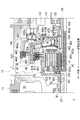
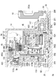
- FIG. 1 is a diagram illustrating a power transmission device 1 according to the first embodiment.
- FIG. 2 is an enlarged view of the power transmission device 1 around the counter gear 5.
- the power transmission device 1 includes a motor 2, a transmission mechanism 3, a counter gear 5 that transmits the output rotation of the transmission mechanism 3 to the differential device 6, and a drive shaft 8 (8A) that transmits the transmitted rotation. , 8B) and a differential device 6.
- a transmission mechanism 3, a counter gear 5, a differential device 6, and a drive shaft 8 (8A, 8B) are provided along the transmission path of the output rotation of the motor 2.
- the output rotation of the motor 2 is changed by the speed change mechanism 3, then decelerated by the counter gear 5 and transmitted to the differential device 6.
- the transmitted rotation is transmitted to the left and right drive wheels (not shown) of the vehicle on which the power transmission device 1 is mounted via the drive shafts 8 (8A, 8B).
- the drive shaft 8A is rotatably connected to the left wheel of the vehicle equipped with the power transmission device 1
- the drive shaft 8B is rotatably connected to the right wheel.
- the transmission mechanism 3 is connected to the downstream of the motor 2
- the counter gear 5 is connected to the downstream of the transmission mechanism 3
- the differential device 6 is connected to the downstream of the counter gear 5.
- Drive shafts 8 (8A, 8B) are connected downstream of the differential device 6.
- the motor housing 10, the outer cover 11, the inner cover 12, the outer case 13, and the inner case 14 constitute the main body case 9 of the power transmission device 1.
- the motor housing 10, the outer cover 11, and the inner cover 12 constitute a case (first case member) for the motor 2.
- the outer case 13 and the inner case 14 form a case (second case member) for accommodating the transmission mechanism 3, the counter gear 5, and the differential device 6.
- the space Sa formed between the outer cover 11 and the inner cover 12 on the inner diameter side of the motor housing 10 is a motor chamber for accommodating the motor 2.
- the space formed between the outer case 13 and the inner case 14 is divided into a space Sb for accommodating the counter gear 5 and the differential device 6 by a partition wall 142 provided in the inner case 14. It is partitioned into a space Sc that houses the mechanism 3. Therefore, the space Sb is a first gear chamber that accommodates the counter gear 5 and the differential device 6, and the space Sc is a second gear chamber that accommodates the transmission mechanism 3.
- the motor 2 has a cylindrical motor shaft 20, a cylindrical rotor core 21 extrapolated to the motor shaft 20, and a stator core 25 that surrounds the outer periphery of the rotor core 21 at predetermined intervals. ing.
- the motor shaft 20 is a tubular member having an insertion hole 200 for the drive shaft 8B, and the motor shaft 20 is extrapolated to the drive shaft 8B.
- the connecting portion 201 on the one end 20a side in the longitudinal direction and the supported portion 202 on the other end 20b side support the connecting portion 201 and the supported portion 202 in the rotation axis X direction. It is formed with an inner diameter larger than the region 203.
- the inner circumference of the connecting portion 201 and the inner circumference of the supported portion 202 are supported by needle bearings NB and NB extrapolated to the drive shaft 8B.
- the motor shaft 20 is provided so as to be rotatable relative to the drive shaft 8B.
- the bearing B1 is extrapolated and fixed to the outer circumference at a position separated from one end 20a to the other end 20b side (left side in the drawing).
- the bearing B1 is restricted from moving to the rotor core 21 side (left side in the drawing) by a step portion 205 provided on the outer periphery of the motor shaft 20.
- the outer circumference of the bearing B1 is rotatably supported by the motor support portion 121 located on the inner diameter side of the inner cover 12.
- the bearing B1 is a step portion 121a provided on the inner circumference of the motor support portion 121, and its movement to the side opposite to the rotor core 21 (right side in the drawing) is restricted. Therefore, in the motor shaft 20, the outer circumference at a position separated from the rotor core 21 at one end 20a is rotatably supported by the cylindrical motor support portion 121 of the inner cover 12 via the bearing B1.
- the bearing B1 is extrapolated and fixed to the outer periphery of the supported portion 202 on the other end 20b side.
- the other end 20b side of the motor shaft 20 is rotatably supported by the cylindrical motor support portion 111 of the outer cover 11 via the bearing B1.
- the park gear 70 of the park lock mechanism 7, which will be described later, is spline-fitted to the outer circumference of the supported portion 202 of the motor shaft 20 and the outer circumference of the region between the bearing B1 and the rotor core 21.
- seal rings SL and SL are provided at one end 10a and the other end 10b in the rotation axis X direction.
- One end 10a of the motor housing 10 is joined to the annular joint portion 120 of the inner cover 12 without a gap by the seal ring SL provided at the one end 10a.
- the other end 10b of the motor housing 10 is joined to the annular joint 110 of the outer cover 11 without a gap by the seal ring SL provided on the other end 10b.
- the motor support portion 121 on the inner cover 12 side is arranged on the inner diameter side of the coil end 253a, which will be described later, with one end portion 21a of the rotor core 21 facing each other with a gap in the rotation axis X direction.
- the motor support portion 111 on the outer cover 11 side is arranged on the inner diameter side of the coil end 253b, which will be described later, with the other end portion 21b of the rotor core 21 facing each other with a gap in the rotation axis X direction.
- the rotor core 21 is arranged between the motor support portion 111 on the outer cover 11 side and the motor support portion 121 on the inner cover 12 side.
- the rotor core 21 is formed by laminating a plurality of silicon steel plates, and each of the silicon steel plates is extrapolated to the motor shaft 20 in a state where the relative rotation with the motor shaft 20 is restricted.
- the silicon steel plate When viewed from the rotation axis X direction of the motor shaft 20, the silicon steel plate has a ring shape, and on the outer peripheral side of the silicon steel plate, magnets of N pole and S pole (not shown) alternate in the circumferential direction around the rotation axis X. It is provided in.
- One end 21a of the rotor core 21 in the X direction of the rotation axis is positioned by the large diameter portion 204 of the motor shaft 20.
- the other end 21b of the rotor core 21 is positioned by a stopper 23 press-fitted into the motor shaft 20.
- the rotor core 21 is fixed to the outer periphery of the support region 203 on the motor shaft.
- the stator core 25 is formed by laminating a plurality of electromagnetic steel plates, and each of the electromagnetic steel plates has a ring-shaped yoke portion 251 fixed to the inner circumference of the motor housing 10 and a rotor core from the inner circumference of the yoke portion 251. It has a teeth portion 252 that protrudes to the 21 side.
- a stator core 25 having a configuration in which the winding 253 is distributed and wound across a plurality of tooth portions 252 is adopted, and the stator core 25 is a coil end 253a, 253b protruding in the rotation axis X direction.
- the length in the rotation axis X direction is longer than that of the rotor core 21 by the amount.
- stator core having a configuration in which windings are centrally wound may be adopted for each of the plurality of tooth portions 252 protruding toward the rotor core 21 side.
- one end 20a of the motor shaft 20 penetrates the motor support portion 121 of the inner cover 12 to the transmission mechanism 3 side (right side in the drawing) and is located in the space Sc.
- a lip seal RS is installed on the inner circumference of the motor support portion 121.
- the lip seal RS seals a gap between the inner circumference of the motor support portion 121 and the outer circumference of the motor shaft 20.
- the lip seal RS is provided to partition the space Sa on the inner diameter side of the motor housing 10 and the space Sc on the inner diameter side of the inner case 14 to prevent oil OL from entering the space Sa from the space Sc side. Has been done.
- FIG. 3 is a diagram illustrating a speed change mechanism 3.
- a speed change mechanism 3 is arranged in the space Sc.
- the speed change mechanism 3 has a planetary gear set 4, a Low brake 46, and a High clutch 47.
- the planetary gear set 4 has a sun gear 41, a ring gear 42, a pinion gear 43, a pinion shaft 44, and a carrier 45.
- the components of the planetary gear set 4 (sun gear 41, ring gear 42, pinion gear 43, pinion shaft 44, carrier 45) are provided on the inner diameter side of the outer wall portion 481 of the clutch drum 48.
- the high clutch 47 includes a drive plate 471 (inner diameter side friction plate) spline-fitted on the outer circumference of the ring gear 42 and a driven plate 472 (outer diameter side friction plate) spline-fitted on the inner circumference of the outer wall portion 481 of the clutch drum 48. ) And a piston 475 that is movably provided in the direction of the rotation axis.
- the clutch drum 48 has an outer wall portion 481, a disk portion 480, an inner wall portion 482, and a connecting portion 483.
- the outer wall portion 481 has a tubular shape that surrounds the rotation shaft X at predetermined intervals.
- the disk portion 480 extends from the end portion of the outer wall portion 481 on the differential device 6 side (right side in the drawing) to the inner diameter side.
- the region on the inner diameter side of the disk portion 480 is a recess 480a recessed in the direction away from the planetary gear set 4.
- the inner wall portion 482 is formed in a tubular shape that surrounds the rotation shaft X at predetermined intervals.
- the inner wall portion 482 extends from the inner diameter side end of the disk portion 480 to the planetary gear assembly 4 side (left side in the drawing), and the tip of the inner wall portion 482 is at the meshing portion between the sun gear 41 and the pinion gear 43. , They face each other with a gap in the X direction of the rotation axis.
- the connecting portion 483 has a cylindrical shape that surrounds the rotation shaft X at predetermined intervals.
- the base end portion 483a in the longitudinal direction is connected to the inner circumference on the distal end side of the inner wall portion 482.
- the connecting portion 483 extends linearly on the extension of the connecting portion 201 of the motor shaft 20 in a direction approaching the motor 2 (to the left in the drawing).
- the tip 483b of the connecting portion 483 is located closer to the motor 2 than the outer wall portion 481.
- the clutch drum 48 composed of the outer wall portion 481, the disk portion 480, the inner wall portion 482, and the connecting portion 483 is provided with an opening facing the motor 2 side, and the connecting portion located on the inner diameter side.
- the sun gear 41 of the planetary gear set 4 is spline-fitted on the outer circumference of the 483.
- the ring gear 42 is located on the outer diameter side of the sun gear 41.
- the ring gear 42 includes a peripheral wall portion 421 that surrounds the outer periphery of the sun gear 41 at predetermined intervals, a disc portion 422 that extends from the end of the peripheral wall portion 421 on the motor 2 side to the inner diameter side, and an end portion of the disc portion 422 on the inner diameter side. It has a connecting portion 423 extending from the motor 2 side to the motor 2.
- the connecting portion 423 has a ring shape that surrounds the rotating shaft X at predetermined intervals, and a connecting portion 201 on the one end 20a side of the motor shaft 20 is spline-fitted on the inner circumference of the connecting portion 423.
- the peripheral wall portion 421 located on the outer diameter side of the connecting portion 423 meshes with the outer circumference of the pinion gear 43 on the inner circumference of the region located on the outer diameter side of the sun gear 41.
- the pinion gear 43 meshes with the inner circumference of the peripheral wall portion 421 of the ring gear 42 and the outer circumference of the sun gear 41.
- the pinion shaft 44 that supports the pinion gear 43 is provided in a direction along an axis X3 parallel to the rotation shaft X.
- One end and the other end of the pinion shaft 44 are supported by a pair of side plate portions 451 and 452 constituting the carrier 45.
- the side plate portions 451 and 452 are provided parallel to each other at intervals in the axis X3 direction.
- One side plate portion 452 located on the motor 2 side extends from the other side plate portion 451 to the rotation axis X side.
- a tubular connecting portion 453 that surrounds the rotation shaft X at predetermined intervals is integrally formed at the end portion 452a on the inner diameter side of the side plate portion 452.
- the connecting portion 453 extends on the rotating shaft X side (inner diameter side) of the connecting portion 201 of the motor shaft 20 in a direction away from the motor 2 along the rotating shaft X.
- the connecting portion 453 is provided so as to cross the inner diameter side of the sun gear 41 from the motor 2 side to the differential device 6 side, and the connecting portion 453 is connected to the hollow shaft 50 on the inner diameter side of the inner wall portion 482 of the clutch drum 48.
- a spline is fitted to the inner circumference of the portion 501.
- a driven plate 472 of the High clutch 47 is spline-fitted on the inner circumference of the outer wall portion 481 of the clutch drum 48.
- the drive plate 471 of the high clutch 47 is spline-fitted to the outer periphery of the peripheral wall portion 421 of the ring gear 42.
- Drive plates 471 and driven plates 472 are alternately provided between the peripheral wall portion 421 of the ring gear 42 and the outer wall portion 481 of the clutch drum 48.
- the retaining plate 473 positioned by the snap ring 474 is located on the motor 2 side of the region where the drive plate 471 and the driven plate 472 are alternately provided, and the piston 475 is located on the differential device 6 side.
- the pressing portion 475a is located.
- the base portion 475b on the inner diameter side of the piston 475 is provided at a position farther from the planetary gear set 4 than the pressing portion 475a on the outer diameter side.
- the base portion 475b on the inner diameter side of the piston 475 is interpolated into the recess 480a on the inner diameter side of the disc portion 480 adjacent in the rotation axis X direction.
- a spring Sp supported by the spring retainer 476 is pressed against the surface of the base portion 475b on the motor 2 side (left side in the drawing) from the rotation axis X direction.
- the piston 475 is urged to the differential device 6 side (right side in the figure) by the urging force acting from the spring Sp.
- a protruding portion 484 protruding toward the differential device 6 is provided at the boundary between the recess 480a and the inner wall portion 482.
- the protrusion 484 is inserted into the inner circumference of the first support portion 141 of the bearing B3.
- An oil OL supply path 141a is open on the inner circumference of the first support portion 141.
- An oil passage 484a for guiding the oil OL supplied from the first support portion 141 side into the recess 480a of the clutch drum 48 is provided inside the protrusion 484.
- the oil OL supplied through the oil passage 484a is supplied to the oil chamber Ra between the base 475b of the piston 475 and the recess 480a, and displaces the piston 475 toward the motor 2.
- the drive plate 471 and the driven plate 472 of the high clutch 47 are gripped between the pressing portion 475a of the piston 475 and the retaining plate 473.
- the relative rotation between the ring gear 42 to which the drive plate 471 is spline-fitted and the clutch drum 48 to which the driven plate 472 is spline-fitted is regulated according to the pressure of the supplied oil OL, and finally. Relative rotation is regulated.
- a drive plate 461 of the Low brake 46 is spline-fitted on the outer periphery of the outer wall portion 481 of the clutch drum 48.
- the driven plate 462 of the Low brake 46 is spline-fitted to the inner circumference of the peripheral wall portion 146 that surrounds the outer circumference of the transmission mechanism 3 at predetermined intervals.
- Drive plates 461 and driven plates 462 are alternately provided between the outer wall portion 481 of the clutch drum 48 and the peripheral wall portion 146 of the inner case 14.
- the retaining plate 463 positioned by the snap ring 464 is located on the motor 2 side of the region where the drive plate 461 and the driven plate 462 are alternately provided, and the piston 465 is located on the differential device 6 side.
- the pressing portion 465a is located.
- the base portion 465b on the inner diameter side of the piston 465 is provided at a position (the position on the right side in the drawing) away from the planetary gear set 4 than the pressing portion 465a on the outer diameter side.
- a recess 142b recessed in a direction away from the planetary gear set 4 is provided in a region facing the base portion 465b of the piston 465.
- the base portion 465b of the piston 465 is interpolated into a recess 142b adjacent to the piston 465 in the X direction of the rotation axis.
- a spring Sp positioned by the recess 142b is connected to the surface of the base portion 465b on the side opposite to the motor 2 (on the right side in the drawing) from the rotation axis X direction.
- the piston 465 is pressed toward the planetary gear assembly 4 side (left side in the figure) by the urging force acting from the spring Sp.
- the drive plate 461 and the driven plate 462 of the Low brake 46 are gripped between the pressing portion 465a of the piston 465 and the retaining plate 463, and in this state, the clutch drum 48 is attached to the inner case 14. Relative rotation is regulated.
- the oil OL supply path 142a is opened in the inner circumference of the recess 142b that accommodates the base portion 465b of the piston 465.
- the oil OL supplied via the supply path 142a is supplied to the oil chamber Rb between the base 465b of the piston 465 and the spring retainer 466, and displaces the piston 465 to the differential device 6 side (right side in the drawing). Let me.
- the Low brake 46, the High clutch 47, and the planetary gear set 4 overlap in the radial direction of the rotating shaft X, and when viewed from the radial outside of the rotating shaft X, the planetary gear set 4 , The Low brake 46, and the High clutch 47 are provided in an overlapping positional relationship.
- the ring gear 42 of the planetary gear set 4 is the input unit for the output rotation of the motor 2, and the carrier 45 is the output unit for the input rotation.
- the speed change mechanism 3 is designed to switch between the low speed stage and the high speed stage by changing the combination of engaging / releasing the high clutch 47 and engaging / releasing the low brake 46.
- the speed change mechanism 3 can be switched between the low speed stage and the high speed stage.
- the low speed stage is realized under the following condition (a), and the high speed stage is realized under the condition (b).
- the transmission mechanism 3 is a two-speed transmission mechanism, and the low-speed stage and the high-speed stage are the same.
- the direction of rotation forward or reverse). Forward / backward switching is possible by forward / reverse rotation of the motor 2.
- the Low brake 46 is a normally closed type engaging element
- the High clutch 47 is a normally open type engaging element.
- the engaging element of the term "normally closed type" in the present specification is an engaging state when operating energy (hydraulic pressure, etc. for hydraulic type, current, etc. for electric type) is not supplied. Means the engaging element that becomes.
- the term “normally open type” engaging element refers to an engaging element that is released when operating energy (hydraulic pressure, etc. for hydraulic pressure type, current, etc. for electric type) is not supplied. means.
- the low brake 35 of the present embodiment is configured to push the engaging element toward the engaging side with a spring (urging member)
- the normally closed type can be easily created.
- the engagement element is pushed toward the release side by a spring like the High clutch 31 of the present embodiment, the normally open type can be easily created.
- the embodiment is not limited to the spring, and a known one may be appropriately selected and used.
- the output rotation of the motor 2 is output to the hollow shaft 50 to which the connecting portion 453 of the carrier 45 is connected after the speed is changed by the speed change mechanism 3.
- the hollow shaft 50 into which the rotation shifted by the speed change mechanism 3 is input is provided with one end 50a in the longitudinal direction on the bearing B5 that supports the support portion 601 of the differential case 60 with a gap in the rotation shaft X direction. ..
- the other end 50b of the hollow shaft 50 is a connecting portion 501 with the planetary gear set 4.
- the outer circumference of the connecting portion 501 is supported by a needle bearing NB interposed between the inner wall portion 482 of the clutch drum 48.
- a gear portion 502 is integrally formed on the outer periphery of the hollow shaft 50 on the one end 50a side.
- Bearings B3 and B3 are extrapolated on both sides of the gear portion 502.
- the bearing B3 on one end 50a side is supported by the first support portion 151 on the support member 15 (see FIG. 1) side, and the bearing B3 on the other end 50b side is supported by the first support portion 141 on the inner case 14. ing.
- a large-diameter gear 52 of the counter gear 5 meshes with the outer circumference of the gear portion 502 so that rotation can be transmitted.
- the large-diameter gear 52 is spline-fitted on the outer circumference of the cylindrical hollow shaft portion 51.
- Bearings B4 are extrapolated to one end 51a and the other end 51b of the hollow shaft portion 51 in the longitudinal direction.
- the bearing B4 extrapolated to one end portion 51a of the hollow shaft portion 51 is inserted into the cylindrical second support portion 135 of the outer case 13.
- One end portion 51a of the hollow shaft portion 51 is rotatably supported by a second support portion 135 of the outer case 13 via a bearing B4.
- the bearing B4 extrapolated to the other end 51b of the hollow shaft 51 is inserted into the cylindrical second support 145 of the inner case 14.
- the other end portion 51b of the hollow shaft portion 51 is rotatably supported by the second support portion 145 of the inner case 14 via the bearing B4.
- the hollow shaft portion 51 of the counter gear 5 is provided along the axis X1 parallel to the rotation shaft X.
- the small diameter gear portion 511 is provided at a position separated from the large diameter gear 52 on the one end portion 51a side (right side in the drawing).
- the small-diameter gear portion 511 is formed integrally with the hollow shaft portion 51 and has an outer diameter R2 smaller than the outer diameter R1 of the large-diameter gear 52 (see FIG. 4: R1> R2).
- FIG. 4 is an enlarged view of the power transmission device 1 around the differential device 6.
- the differential case 60 is formed in a hollow shape for accommodating the shaft 61, the bevel gears 62A and 62B, and the side gears 63A and 63B.
- tubular support portions 601 and 602 are provided on both sides of the rotation axis X direction (left-right direction in the drawing). The support portions 601 and 602 extend along the rotation axis X in a direction away from the shaft 61.
- Bearing B5 is extrapolated to the support portion 602 of the differential case 60.
- the support portion 602 of the differential case 60 is held by the ring-shaped first support portion 131 of the outer case 13 via the bearing B5.
- a drive shaft 8A penetrating the opening 130 of the outer case 13 is inserted into the support portion 602 from the rotation axis X direction, and the drive shaft 8A is rotatably supported by the support portion 602.
- a lip seal RS is fixed to the inner circumference of the opening 130, and the lip portion (not shown) of the lip seal RS elastically contacts the outer circumference of the drive shaft 8A to open the outer circumference of the drive shaft 8A.
- the gap between the inner circumference and the inner circumference of the portion 130 is sealed.
- Bearing B5 is extrapolated to the support portion 601 of the differential case 60.
- the support portion 601 of the differential case 60 is rotatably supported by the first support portion 151 of the support member 15 via the bearing B5.
- the support member 15 has a tubular portion 152 extending from the outer circumference of the first support portion 151 to the motor 2 side (right side in the drawing) and an opening on the tip end side of the tubular portion 152 all around. It has a flange portion 153 that surrounds it.
- the flange portion 153 of the support member 15 is fixed to the first support portion 141 of the inner case 14 by a bolt B penetrating the flange portion 153.
- the support portion 601 of the differential case 60 is rotatably supported by the support member 15 via the bearing B5.
- the support member 15 is fixed to the inner case 14. Therefore, the support portion 601 of the differential case 60 is supported by the inner case 14 which is a fixed side member via the bearing B5 and the support member 15.
- a drive shaft 8B penetrating the opening 114 of the outer cover 11 is inserted into the support portion 601 of the differential case 60 from the rotation axis X direction.
- the drive shaft 8B is provided so as to cross the motor shaft 20 of the motor 2, the transmission mechanism 3, and the inner diameter side of the hollow shaft 50 in the rotation axis X direction, and the tip end side of the drive shaft 8B rotates on the support portion 601. It is supported as much as possible.
- a lip seal RS is fixed to the inner circumference of the opening 114 of the outer cover 11, and the lip portion (not shown) of the lip seal RS elastically contacts the outer circumference of the drive shaft 8B, so that the drive shaft 8B The gap between the outer circumference of the shaft and the inner circumference of the opening 114 is sealed.
- side gears 63A and 63B are spline-fitted on the outer periphery of the tip of the drive shaft 8 (8A, 8B), and the side gears 63A and 63B and the drive shaft 8 (8A) are fitted. , 8B) are integrally rotatably connected around the rotation axis X.
- the differential case 60 is provided with shaft holes 60a and 60b penetrating in a direction orthogonal to the rotation axis X at positions symmetrical with respect to the rotation axis X.
- the shaft holes 60a and 60b are located on the axis Y orthogonal to the rotation axis X, and the shaft 61 is inserted into the shaft holes 60a and 60b.
- the shaft 61 is fixed to the differential case 60 with a pin P, and the shaft 61 is prohibited from rotating around the axis Y.
- the shaft 61 is located between the side gears 63A and 63B in the differential case 60, and is arranged along the axis Y.
- bevel gears 62A and 62B are externally inserted and rotatably supported on the shaft 61.
- Two bevel gears 62A and 62B are provided at intervals in the longitudinal direction of the shaft 61 (the axial direction of the axis Y), and the bevel gears 62A and 62B are arranged so that their teeth face each other. ing.
- side gears 63A and 63B are located on both sides of the bevel gears 62A and 62B in the axial direction of the rotating shaft X.
- Two side gears 63A and 63B are provided at intervals in the axial direction of the rotating shaft X with their teeth facing each other, and the bevel gears 62A and 62B and the side gears 63A and 63B are provided with each other. It is assembled with the teeth engaged.
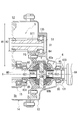
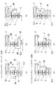
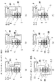
- FIG. 5 is a diagram illustrating the park lock mechanism 7.
- the position of the parking pole 71 when the park lock mechanism 7 is inactive is shown by a solid line, and the position of the parking pole 71 when the park lock mechanism 7 is inactive is virtual. It is shown by a line.
- FIG. 5B shows the positional relationship between the cam 73 of the park rod 72 and the cam surface 751 of the support actuator 75 when the park lock mechanism 7 is not operating.
- FIG. 5B shows the positional relationship between the cam 73 of the park rod 72 and the cam surface 751 of the support actuator 75 when the park lock mechanism 7 is in the operating state.
- the park lock mechanism 7 is provided to maintain the parked state of the vehicle equipped with the power transmission device 1.
- the park lock mechanism 7 includes a park gear 70, a parking pole 71, a park rod 72, and a support actuator 75.
- the park gear 70 is spline-fitted on the outer periphery of the supported portion 202 of the motor shaft 20 of the motor 2, and the park gear 70 is connected to the motor shaft 20 so as not to rotate relative to each other.
- the parking pole 71 has a plate-shaped base 710 that can rotate around an axis X2 parallel to the rotation axis X of the park gear 70.
- the base portion 710 is provided so as to cross the axis X2 when viewed from the direction of the axis X2.
- the base portion 710 has a parking claw 71a that engages and disengages with the tooth groove portion 70a of the park gear 70 on one side of the axis X2.
- the base portion 710 has a operated portion 71b operated by the cam 73 of the park rod 72 on the other side of the axis X2.
- An urging force in the direction of bringing the operated portion 71b closer to the support actuator 75 acts on the parking pole 71 from a spring (not shown).
- the parking pole 71 is held at a position where the operated portion 71b is brought into contact with the upper surface of the support actuator 75 by the urging force of the spring (see (a) in FIG. 5).
- the support actuator 75 has a cam surface 751 that forms an arc shape when viewed from the axis X2 direction on a portion facing the parking pole 71 (operated portion 71b).
- the cam surface 751 is an inclined surface that is inclined toward the tip end side of the park rod 72 and is inclined toward the operated portion 71b of the parking pole 71 (see (b) in FIG. 5).
- the park rod 72 is provided so as to be movable back and forth in the direction of the axis X2a parallel to the axis X2.
- the stopper 74 is fixed to the tip of the park rod 72.
- a cam 73 urged by the spring Sp is in contact with the stopper 74 from the axis X2a direction.
- the park rod 72 When the park lock mechanism 7 is in the non-operating state, the park rod 72 is arranged at a position where the cam 73 is separated from the cam surface 751 of the support actuator 75 and the operated portion 71b of the parking pole 71. (See (b) in FIG. 5). In this state, the parking pole 71 is arranged at the position shown by the solid line in FIG. 5A.
- the park rod 72 When the park lock mechanism 7 is in the operating state, the park rod 72 is arranged at a position where the cam 73 is inserted between the cam surface 751 of the support actuator 75 and the operated portion 71b of the parking pole 71. (See (c) of FIG. 5).
- the parking pole 71 In this state, the parking pole 71 is arranged at the position shown by the virtual line in FIG. 5A, and the parking claw 71a on the tip side is arranged at the position where the parking claw 71a on the tip side is engaged with the tooth groove portion 70a on the outer periphery of the park gear 70. Will be done.
- the transmission mechanism 3 As shown in FIG. 1, in the power transmission device 1, the transmission mechanism 3, the counter gear 5, the differential device 6, and the drive shaft 8 (8A, 8B) are arranged along the transmission path of the output rotation of the motor 2. , Are provided.
- the rotation is input to the transmission mechanism 3 via the motor shaft 20 that rotates integrally with the rotor core 21.
- the ring gear 42 of the planetary gear set 4 serves as a rotation input unit
- the carrier 45 serves as a rotation output unit.
- the low speed stage is realized when the Low brake 46 is engaged, and the high speed stage is realized when the High clutch 47 is engaged.
- the rotation input to the speed change mechanism 3 is output from the connecting portion 453 of the carrier 45 to the hollow shaft 50 after the speed change. Then, the rotation input to the hollow shaft 50 is input to the counter gear 5 via the large diameter gear 52 meshed with the gear portion 502 of the hollow shaft 50.
- the large-diameter gear 52 that meshes with the gear portion 502 of the hollow shaft 50 serves as an input unit for the output rotation of the motor 2, and the small-diameter gear portion 511 that meshes with the final gear FG of the differential case 60 inputs. It is the output part of the rotation.
- the outer diameter R2 of the small diameter gear portion 511 is smaller than the outer diameter R1 of the large diameter gear 52 (see FIG. 4). Therefore, the rotation input to the counter gear 5 is greatly decelerated and then output to the differential case 60 (differential device 6) via the final gear FG in which the small diameter gear portion 511 meshes.
- the drive shaft 8 (8A, 8B) rotates around the rotation axis X by rotating the differential case 60 around the rotation axis X by the input rotation.
- the output rotation of the motor 2 is transmitted to the left and right drive wheels (not shown) of the vehicle on which the power transmission device 1 is mounted.
- the Low brake 46 is a normally closed type engaging element (fastening element), and is always maintained in the fastened state when the power transmission device 1 is stopped or parked.
- the High clutch 47 is a normally open type engaging element (fastening element), and is always maintained in an released state when the power transmission device 1 is stopped.
- the power transmission device 1 includes a park lock mechanism 7 (see FIG. 1) for maintaining a parked state of a vehicle equipped with the power transmission device 1.
- the park lock mechanism 7 is controlled by a vehicle control device 90 (see FIG. 6) equipped with the power transmission device 1.
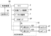
- FIG. 6 is a diagram illustrating a controlled object of the control device 90 included in the power transmission device 1.
- FIG. 7 is a flowchart illustrating operation control of the park lock mechanism 7 carried out by the control device 90.
- the control device 90 drives / stops the motor 2, operates / does not operate the park lock mechanism 7 by moving the park rod 72 (see FIG. 5) forward and backward, drives / stops the oil pump OP, and inside the hydraulic control circuit 92.
- the pressure regulating valves 921 and 925 of the above are controlled.
- the engagement / release of the high clutch 47 and the engagement / release of the low brake 46 are performed by controlling the pressure regulating valves 921 and 925 in the hydraulic control circuit 92.
- the parking claw 71a of the parking pole 71 is engaged with the tooth groove portion 70a on the outer periphery of the park gear 70 to put the park lock mechanism 7 into an operating state.
- the parking claw 71a of the parking pole 71 faces the region between the adjacent tooth grooves 70a and 70a on the outer circumference of the park gear 70, when the park lock mechanism 7 is to be operated, the parking claw 71a is opened. It may not be possible to engage with the tooth groove portion 70a.
- the park lock mechanism 7 remains inactive and cannot prevent the movement of the vehicle equipped with the power transmission device 1. It becomes.
- the control device 90 controls the operation of the park lock mechanism 7.
- step S101, Yes the control device 90 steps.
- the process of S102 is executed.
- the control device 90 identifies the angular position (phase) around the rotation axis X of the park gear 70 from the output signal of the phase sensor 95 (see FIG. 6). Then, the control device 90 determines from the specified angular position of the park gear 70 whether or not the tooth groove portion 70a on the outer periphery of the park gear 70 is at a position facing the parking claw 71a of the parking pole 71. That is, it is determined whether or not the tooth groove portion 70a of the park gear 70 and the parking claw 71a of the parking pole 71 are in a positional relationship in which they can mesh with each other, and whether or not they are in a meshing position.
- step S103 When the tooth groove portion 70a of the park gear 70 and the parking claw 71a of the parking pole 71 are in the meshing position, the control device 90 shifts to the process of step S103. As a result, the park rod 72 of the park lock mechanism 7 is moved from the position shown in FIG. 5 (b) to the position shown in FIG. 5 (c) by a driving device (not shown).
- the cam 73 of the park rod 72 is inserted between the cam surface 751 of the support actuator 75 and the operated portion 71b of the parking pole 71, and the parking pole 71 is counterclockwise in FIG. 5A. It rotates in the clockwise direction. Then, the parking claw 71a of the parking pole 71 engages with the tooth groove portion 70a on the outer periphery of the park gear 70, and the rotation of the motor shaft 20 of the motor 2 is restricted. That is, the park lock mechanism 7 is switched from the non-operating state to the operating state.
- the Low brake 46 is a normally closed type engaging element (fastening element), and is always maintained in the fastened state when the power transmission device 1 is stopped and parked.
- the High clutch 47 is a normally open type engaging element (fastening element), and is always maintained in an released state when the power transmission device 1 is stopped.
- the power transmission device 1 employs a normally closed type engaging element (Low brake 46), the rotation of the motor shaft 20 of the motor 2 is regulated by the park lock mechanism 7, so that the power transmission device 1 is used. It is possible to regulate the movement of the vehicle equipped with 1.
- a normally closed type engaging element Low brake 46
- step S102 of FIG. 7 when the tooth groove portion 70a of the park gear 70 and the parking claw 71a of the parking pole 71 are not in the meshing positions (steps S102, No), the process proceeds to step S104.
- the control device 90 operates the automatic braking mechanism 91 mounted on the vehicle.
- the automatic braking mechanism 91 is, for example, a system that regulates the movement of the vehicle by putting the braking system of the drive wheels into an operating state regardless of whether or not the brake pedal is operated.
- the control device 90 releases the Low brake 46, which is a normally closed type engaging element. Specifically, the control device 90 adjusts the discharge pressure of the oil pump OP with the pressure regulating valve 925 and supplies it to the oil chamber Rb attached to the Low brake 46. As a result, the hydraulic pressure supplied to the Low brake 46 switches from the engaged state to the released state. As a result, the power transmission device 1 is in a state (neutral state) in which the rotational driving force is not transmitted between the upstream side (motor 2 side) and the downstream side (counter gear 5) of the transmission mechanism 3. ..
- step S106 the control device 90 drives the motor 2 to rotate the motor shaft 20 around the rotation axis X.
- the control device 90 arranges the tooth groove portion 70a on the outer periphery of the park gear 70 at a position facing the parking claw 71a of the parking pole 71 based on the output signal of the phase sensor 95. That is, the tooth groove portion 70a of the park gear 70 and the parking claw 71a of the parking pole 71 are phase-aligned.
- step S107 the control device 90 moves the park rod 72 of the park lock mechanism 7 from the position shown in FIG. 5 (b) to the position shown in FIG. 5 (c) by a drive device (not shown).
- the parking claw 71a of the parking pole 71 is engaged with the tooth groove portion 70a on the outer periphery of the park gear 70.
- the park lock mechanism 7 is switched from the non-operating state to the operating state, and the rotation of the motor shaft 20 of the motor 2 is restricted.
- step S108 the control device 90 engages the Low brake 46, which is a normally closed type engaging element. Specifically, the control device 90 controls the oil pump OP and the pressure regulating valve 925 to stop the supply of oil to the oil chamber Rb attached to the Low brake 46. As a result, the piston 465 of the Low brake 46 (see FIG. 3) is moved to the planetary gear set 4 side (left side in the drawing) by the urging force acting from the spring Sp, and the Low brake 46 is engaged.
- the power transmission device 1 is in a state (Low state) in which the upstream side (motor 2 side) and the downstream side (counter gear 5) of the transmission mechanism 3 are connected so as to be capable of rotational transmission.
- the rotation of the motor shaft 20 is regulated by the park lock mechanism 7, so that the drive shaft 8 (8A, 8B) located on the downstream side of the motor 2 is connected to the drive shaft 8 (8A, 8B).
- the rotation of the left and right drive wheels is restricted.
- the power transmission device 1 employs a normally closed type engaging element (Low brake 46), the rotation of the motor shaft 20 of the motor 2 is regulated by the park lock mechanism 7, so that the power transmission device 1 is used. The movement of the vehicle equipped with 1 is restricted.
- a normally closed type engaging element Low brake 46
- step S109 the control device 90 releases the automatic brake operated in the above-mentioned step S104.
- the power transmission device 1 has the following configuration.
- the power transmission device 1 is Motor 2 and A normally closed type Low brake 46 (engagement element) connected to the downstream of the motor 2 and The counter gear 5 (reduction gear) connected to the downstream of the Low brake 46 and It has a park lock mechanism 7 that locks a motor shaft 20 that is an upstream rotating element of the Low brake 46.
- the drive shaft 8 (8A, 8B) Since the counter gear 5 is located between the motor shaft 20 whose rotation is regulated by the park lock mechanism 7 and the drive shaft 8 (8A, 8B) connected to the drive wheels, the drive shaft 8 (8A, 8B) is located.
- the rotation (torque) input from the) side to the motor 2 side can be reduced. It is preferable that the torque input from the output side (driving wheel side) to the park lock mechanism 7 is as small as possible when the vehicle equipped with the power transmission device 1 is stopped or parked.
- the internal combustion engine can be used as the drive source even if the normally closed type Low brake 46 (engagement element) is provided on the transmission path of the power transmission device.
- the normally closed type Low brake 46 engagement element
- the engaging element (Low brake 46) on the power transmission path as a normally closed type engaging element, the vehicle equipped with the power transmission device 1 can be stopped.
- the drive wheels and the drive source (motor) can be put into a power transmission state during parking. Therefore, since the park lock mechanism 7 can be arranged upstream of the engaging element, the torque input to the park lock mechanism from the output side (drive wheel side) when the vehicle is stopped can be reduced.
- the power transmission device 1 has the following configuration.
- the motor shaft 20 which is the output shaft of the motor 2 is Connecting portion 201 (first shaft portion) that does not overlap radially with the rotor core 21 of the motor 2
- a supported portion 202 (second shaft portion) that does not overlap radially with the rotor core 21 of the motor 2 and It is divided into a support region 203 (third shaft portion) that overlaps the rotor core 21 of the motor 2 in the radial direction and is sandwiched between the connecting portion 201 and the supported portion 202.
- the connecting portion 201 is connected to the normally closed type Low brake 46, and is connected to the normally closed type Low brake 46.
- the supported portion 202 is locked by the park lock mechanism 7.
- the power transmission device 1 can be further miniaturized.
- the power transmission device 1 has the following configuration. (3) A part of the park lock mechanism 7 (park gear 70) is provided by utilizing the space on the inner peripheral side (inner diameter side) of the stator core 25 of the motor 2, and a part of the park lock mechanism 7 (park gear 70). ) Is located on the inner peripheral side (inner diameter side) of the coil end 253b of the stator core 25.
- the power transmission device 1 can be enlarged in the rotation axis X direction by providing a part (park gear 70) of the park lock mechanism 7 by utilizing the space on the inner peripheral side of the coil end 253b.
- the park lock mechanism 7 can be provided.
- the power transmission device 1 has the following configuration. (4) The power transmission device 1 has a control device 90 (control unit) that controls the operation of the park lock mechanism 7. In the vehicle equipped with the power transmission device 1, the control device 90 releases the Low brake 46, which is a normally closed clutch, when the parking range (P range) is selected, and then the park lock mechanism 7 The motor 2 is rotated so that the parking claw 71a and the tooth groove portion 70a on the outer periphery of the park gear 70 are in a position where they mesh with each other.
- the control device 90 controls the operation of the park lock mechanism 7.
- the control device 90 releases the Low brake 46, which is a normally closed clutch, when the parking range (P range) is selected, and then the park lock mechanism 7
- the motor 2 is rotated so that the parking claw 71a and the tooth groove portion 70a on the outer periphery of the park gear 70 are in a position where they mesh with each other.
- the park lock mechanism 7 when the park lock mechanism 7 is operated, the parking claw 71a of the park lock mechanism 7 and the tooth groove portion 70a on the outer periphery of the park gear 70 are in a positional relationship in which they do not mesh with each other (phases are different). If it is out of alignment), the power transmission device 1 can be temporarily put into the neutral state to match the phases of the parking claw 71a and the tooth groove portion 70a. As a result, after matching the phases of the parking claw 71a and the tooth groove portion 70a, the parking claw 71a is engaged with the tooth groove portion 70a on the outer periphery of the park gear 70, and the park lock mechanism 7 is reliably switched to the operating state. Can be done.
- the phase of the park gear 70 may be a detection means for detecting the rotation angle of the park gear, for example, a sensor may be provided separately, or the rotation angle sensor of the motor may also be used.
- the power transmission device 1 has the following configuration. (5)
- the control device 90 operates the automatic brake mechanism 91 while the Low brake 46, which is a normally closed clutch, is released.
- a parking range (P range)
- the driver of the vehicle intends to keep the vehicle stopped and parked.
- the Low brake 46 which is a normally closed clutch, is released for the above-mentioned phase matching, the rotating elements (for example, drive shafts 8 (8A, 8B)) located on the downstream side of the Low brake 46 are released. It becomes a neutral state where it can rotate.
- the vehicle equipped with the power transmission device 1 when stopped or parked on a slope or the like, the vehicle may move when the Low brake 46 is released. In such a case, the vehicle may move. , It may give a sense of discomfort to the occupants of the vehicle.
- the automatic braking mechanism mounted on the vehicle is operated while the Low brake 46 is in the released state to move the vehicle. It can be stopped. In this case, until the operation of the park lock mechanism 7 is completed, that is, the parking claw 71a and the tooth groove portion 70a of the park gear 70 mesh with each other, and the low brake 46, which is a normally closed type engaging element, is refastened. It is preferable to hold the automatic braking mechanism in an operating state until this is done.
- the movement of the vehicle can be reliably prevented. Further, even if the driver releases the brake pedal before the operation of the automatic brake mechanism 91 is completed, the vehicle can be held in a stopped and parked state.
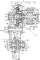
- FIG. 8 is a diagram illustrating the power transmission device 1A according to the second embodiment.
- FIG. 9 is an enlarged view of the power transmission device 1A around the speed change mechanism 3A.
- the power transmission device 1A includes a motor 2, a transmission mechanism 3A, a counter gear 5 that transmits the output rotation of the transmission mechanism 3A to the differential device 6, and a drive shaft 8 (8A) that transmits the transmitted rotation. , 8B) and a differential device 6.
- a transmission mechanism 3A, a counter gear 5, a differential device 6, and a drive shaft 8 (8A, 8B) are provided along the transmission path of the output rotation of the motor 2.
- the output rotation of the motor 2 is changed by the speed change mechanism 3A, then decelerated by the counter gear 5 and transmitted to the differential device 6.
- the transmitted rotation is transmitted to the left and right drive wheels (not shown) of the vehicle on which the power transmission device 1A is mounted via the drive shafts 8 (8A, 8B).
- the transmission mechanism 3A is connected to the downstream of the motor 2
- the counter gear 5 is connected to the downstream of the transmission mechanism 3A
- the differential device 6 is connected to the downstream of the counter gear 5.
- Drive shafts 8 (8A, 8B) are connected downstream of the differential device 6.
- the motor 2 and the transmission mechanism 3A are coaxially arranged on the common rotation shaft Xa.
- the rotary shaft Xb of the counter gear 5 and the rotary shafts Xc of the differential device 6 and the drive shafts 8 (8A, 8B) are provided parallel to the rotary shaft Xa.
- the power transmission device 1A is a so-called three-axis type power transmission device in which the rotation axes Xa, Xb, and Xc involved in the transmission of rotation are arranged so as to be parallel to each other.
- the main body case 9 of the power transmission device 1A is configured by the motor housing 10, the outer cover 11, the inner cover 12, the outer case 13, and the inner case 14.
- the motor housing 10, the outer cover 11, and the inner cover 12 constitute a case (first case member) for the motor 2.
- the outer case 13 and the inner case 14 form a case (second case member) for accommodating the transmission mechanism 3A, the counter gear 5, and the differential device 6.
- the motor 2 has a cylindrical motor shaft 20, a cylindrical rotor core 21 extrapolated to the motor shaft 20, and a stator core 25 that surrounds the outer periphery of the rotor core 21 at predetermined intervals. ing.
- bearings B1 and B1 are extrapolated on both sides of the rotor core 21.
- the motor shaft 20 is rotatably supported by the motor support portion 111 of the outer cover 11 and the motor support portion 121 of the inner cover 12 via bearings B1 and B1.
- the park gear 70 of the park lock mechanism 7 described later is the outer circumference of the supported portion 202 of the motor shaft 20, and is the outer circumference of the region between the bearing B1 and the rotor core 21. Spline mated.
- a connecting portion 201 having an outer diameter smaller than that of the large diameter portion 208 on the other end 20b side is provided on one end 20a side of the motor shaft 20.
- the connecting portion 201 of the motor shaft 20 is spline-fitted to the inner circumference of the connecting portion 423 on the transmission mechanism 3A side in the ring-shaped third support portion 147 of the inner case 14.
- the speed change mechanism 3A includes a planetary gear set 4, a high clutch 47, and a low brake 46.
- the planetary gear set 4 has a sun gear 41, a ring gear 42, a pinion gear 43, a pinion shaft 44, and a carrier 45.
- the components of the planetary gear set 4 (sun gear 41, ring gear 42, pinion gear 43, pinion shaft 44, carrier 45) are provided on the inner diameter side of the outer wall portion 481 of the clutch drum 48.
- the high clutch 47 includes a drive plate 471 (inner diameter side friction plate) spline-fitted on the outer circumference of the ring gear 42 and a driven plate 472 (outer diameter side friction plate) spline-fitted on the inner circumference of the outer wall portion 481 of the clutch drum 48. ), And a piston 475 provided so as to be movable in the direction of the rotation axis Xa.
- the clutch drum 48 has an outer wall portion 481, a disk portion 480, an inner wall portion 482, and a connecting portion 483.
- the outer wall portion 481 has a tubular shape that surrounds the rotation shaft Xa at predetermined intervals.
- the disk portion 480 extends from the end portion of the outer wall portion 481 opposite to the motor 2 (left side in the drawing) to the inner diameter side.
- An inner wall portion 482 is provided at an end portion on the inner diameter side of the disk portion 480.
- the inner wall portion 482 is formed in a tubular shape that surrounds the rotation shaft Xa at predetermined intervals.
- the inner wall portion 482 extends from the end on the inner diameter side of the disk portion 480 to the planetary gear assembly 4 side (right side in the drawing), and the tip of the inner wall portion 482 is located on the inner diameter side of the Low brake 46. ..
- the connecting portion 483 has a cylindrical shape that surrounds the rotation shaft Xa at predetermined intervals.
- the base end portion 483a in the longitudinal direction is connected to the inner circumference on the distal end side of the inner wall portion 482.
- the connecting portion 483 extends linearly in a direction approaching the motor 2 (to the right in the drawing).
- the clutch drum 48 composed of the outer wall portion 481, the disk portion 480, the inner wall portion 482, and the connecting portion 483 is provided with an opening facing the motor 2 side.
- the support shaft 30 is a shaft-shaped member in which a small diameter portion 301 and a large diameter portion 302 are integrally formed by arranging them in the direction of the rotation axis Xa, and is arranged in a direction along the rotation axis Xa. ing.
- the support shaft 30 is arranged coaxially with the motor shaft 20. As shown in FIG. 9, in the large diameter portion 302 located on the motor 2 side (right side in the drawing) of the support shaft 30, an accommodating hole 302a capable of receiving the motor shaft 20 is opened in a portion facing the motor shaft 20. doing.
- a shaft portion 424 provided at the tip of the motor shaft 20 is inserted into the accommodating hole 302a.
- a needle bearing NB extrapolated to the shaft portion 424 is in contact with the inner circumference of the accommodating hole 302a, and the support shaft 30 and the motor shaft 20 are rotatably engaged with each other at the accommodating hole 302a.
- a disc-shaped flange portion 303 is integrally formed at the end of the large diameter portion 302 on the motor 2 side.
- the flange portion 303 is provided in a direction orthogonal to the rotation axis Xa, and the outer circumference of the flange portion 303 extends to the side of the connecting portion 483 of the clutch drum 48.
- a sun gear 41 of the planetary gear set 4 is spline-fitted on the outer circumference of the connecting portion 483.
- the ring gear 42 is located on the outer diameter side of the sun gear 41.
- the ring gear 42 includes a peripheral wall portion 421 that surrounds the outer periphery of the sun gear 41 at predetermined intervals, a disc portion 422 that extends from the end of the peripheral wall portion 421 on the motor 2 side to the inner diameter side, and a motor 2 from the inner diameter side of the disc portion 422. It has a connecting portion 423 extending to the side and a shaft portion 424 extending from the inner diameter side end of the disc portion 422 to the side opposite to the motor 2.
- the outer circumference of the pinion gear 43 meshes with the inner circumference of the region located on the outer diameter side of the sun gear 41.
- the pinion gear 43 meshes with the inner circumference of the peripheral wall portion 421 on the ring gear 42 side and the outer circumference of the sun gear 41.
- the pinion shaft 44 that supports the pinion gear 43 is provided in a direction along an axis X3 parallel to the rotation shaft Xa of the motor 2.
- One end and the other end of the pinion shaft 44 are supported by a pair of side plate portions 451 and 452 constituting the carrier 45.
- the side plate portions 451 and 452 are provided parallel to each other at intervals in the axis X3 direction.
- One side plate portion 452 located on the motor 2 side extends to the rotation axis Xa side from the other side plate portion 451.
- the inner diameter side end portion 452a of the side plate portion 452 is connected to the outer circumference of the flange portion 303 on the support shaft 30 side.
- the peripheral wall portion 421 of the ring gear 42 has a ring shape that surrounds the rotation shaft Xa at predetermined intervals, and the drive plate 471 of the high clutch 47 is spline-fitted on the outer periphery of the peripheral wall portion 421.
- the driven plate 472 of the high clutch 47 is spline-fitted to the inner circumference of the outer wall portion 481 of the clutch drum 48.
- Drive plates 471 and driven plates 472 are alternately provided between the peripheral wall portion 421 of the ring gear 42 and the outer wall portion 481 of the clutch drum 48.
- a retaining plate 473 positioned by the snap ring 474 is located on the motor 2 side of the region where the drive plate 471 and the driven plate 472 are alternately provided, and the piston 475 is located on the opposite side of the motor 2.
- the pressing portion 475a of the above is located.
- the piston 475 has a base portion 475b provided in a direction orthogonal to the rotation axis Xa.
- a tubular wall portion 475c extending toward the planetary gear assembly 4 side (right side in the drawing) is provided at a substantially central portion of the base portion 475b in the radial direction of the rotating shaft Xa.
- a slit 475d recessed in a direction away from the disc portion 480 of the clutch drum 48 (in the right direction in the drawing) is provided in the region where the cylinder wall portion 475c is provided.
- a guide piece 480b extending from the disk portion 480 of the clutch drum 48 to the motor 2 side is inserted into the slit 475d.
- the spring Sp supported by the spring retainer 476 is pressed against the surface of the base portion 475b on the motor 2 side from the rotation axis X direction.
- the piston 475 is urged to the disk portion 480 side (left side in the drawing) of the clutch drum 48 by the urging force acting from the spring Sp.
- a protruding portion 484 protruding toward the differential device 6 is provided at the boundary between the disc portion 480 and the inner wall portion 482.
- the protrusion 484 is inserted into the inner circumference of the first support portion 151 of the bearing B2.
- An oil OL supply path 151a is open on the inner circumference of the first support portion 151.
- an oil passage 484a for guiding the oil OL supplied from the first support portion 151 side to the oil chamber Ra between the disc portion 480 of the clutch drum 48 and the base portion 475b of the piston 475. Is provided.
- the oil OL supplied to the oil chamber Ra via the oil passage 484a displaces the piston 475 to the motor 2 side (right side in the figure). At this time, the displacement of the piston 475 in the rotation axis Xa direction is guided by the guide piece 480b provided on the disk portion 480 and the slit 475d on the piston 475 side into which the guide piece 480b is inserted.
- a drive plate 461 of the Low brake 46 is spline-fitted on the outer periphery of the outer wall portion 481 of the clutch drum 48.
- the driven plate 462 of the Low brake 46 is spline-fitted to the inner circumference of the peripheral wall portion 156 of the support member 15 that surrounds the outer circumference of the transmission mechanism 3A at predetermined intervals.
- Drive plates 461 and driven plates 462 are alternately provided between the outer wall portion 481 of the clutch drum 48 and the peripheral wall portion 156 of the support member 15.
- the retaining plate 463 positioned by the snap ring 464 is located on the motor 2 side of the region where the drive plate 461 and the driven plate 462 are alternately provided, and the piston 465 is located on the opposite side of the motor 2.
- the pressing portion 465a of the above is located.
- the base portion 465b on the inner diameter side of the piston 465 is provided at a position (the position on the left side in the drawing) away from the planetary gear set 4 than the pressing portion 465a on the outer diameter side.
- a recess 157b recessed in a direction away from the planetary gear set 4 is provided in a region facing the base portion 465b of the piston 465.
- the base portion 465b of the piston 465 is interpolated into a recess 157b adjacent to the piston 465 in the direction of the rotation axis Xa.
- a spring Sp positioned by the recess 157b is connected to the surface of the base portion 465b on the motor 2 side (left side in the drawing) from the direction of the rotation axis Xa.
- the piston 465 is pressed toward the planetary gear assembly 4 side (right side in the figure) by the urging force acting from the spring Sp.
- the drive plate 461 and the driven plate 462 of the Low brake 46 are gripped between the pressing portion 465a of the piston 465 and the retaining plate 463, and in this state, the clutch drum 48 is attached to the support member 15. Relative rotation is regulated.
- an oil OL supply path 157a is opened in the inner circumference of the recess 157b accommodating the base portion 465b of the piston 465.
- the oil OL supplied via the supply path 157a is supplied to the oil chamber Rb between the base 465b of the piston 465 and the spring retainer 466, and the piston 465 is placed on the opposite side of the planetary gear set 4 (left side in the drawing). ).
- the Low brake 46, the High clutch 47, and the planetary gear set 4 overlap in the radial direction of the rotating shaft Xa, and when viewed from the radial outside of the rotating shaft Xa, the planetary gear set 4 , The Low brake 46, and the High clutch 47 are provided in an overlapping positional relationship.
- the ring gear 42 of the planetary gear set 4 is the input unit for the output rotation of the motor 2, and the carrier 45 is the output unit for the input rotation.
- the speed change mechanism 3A is designed to switch between the low speed stage and the high speed stage by changing the combination of engaging / releasing the high clutch 47 and engaging / releasing the low brake 46.
- the speed change mechanism 3A can be switched between the low speed stage and the high speed stage.
- the low speed stage is realized under the following condition (a), and the high speed stage is realized under the condition (b).
- the transmission mechanism 3A is a two-speed transmission mechanism, and the low-speed stage and high-speed stage are the same.
- the direction of rotation forward or reverse). Forward / backward switching is possible by forward / reverse rotation of the motor 2.
- the Low brake 46 is a normally closed type engaging element
- the High clutch 47 is a normally open type engaging element.
- the output rotation of the motor 2 is output from the side plate portion 452 of the carrier 45 to the support shaft 30 after the speed is changed by the transmission mechanism 3A.
- the support shaft 30 extends in a direction away from the motor 2 along the rotation shaft Xa.
- the hollow shaft 32 is spline-fitted on the outer circumference of the small diameter portion 301.
- bearings B2 and B2 are extrapolated on both sides in the direction of the rotating shaft Xa.
- the hollow shaft 32 is supported by a third support portion 147 on the outer case 13 side and a first support portion 151 on the support member 15 side via bearings B2 and B2.
- the gear portion 321 is integrally formed on the outer periphery of the region between the bearings B2 and B2.
- a large-diameter gear 52 of the counter gear 5 meshes with the outer circumference of the gear portion 321 so as to be able to transmit rotation.
- the large-diameter gear 52 is spline-fitted on the outer circumference of the cylindrical hollow shaft portion 51.
- Bearings B3 and B3 are extrapolated to one end 51a and the other end 51b of the hollow shaft portion 51 in the longitudinal direction.
- One end portion 51a of the hollow shaft portion 51 is rotatably supported by a second support portion 135 of the outer case 13 via a bearing B3.
- the other end 51b of the hollow shaft 51 is rotatably supported by the second support 145 of the inner case 14 via the bearing B3.
- the hollow shaft portion 51 of the counter gear 5 is provided along the rotation shaft Xb parallel to the rotation shaft Xa.
- a small diameter gear portion 511 is provided adjacent to the other end portion 51b side (right side in the drawing) when viewed from the large diameter gear 52.
- the small-diameter gear portion 511 is formed integrally with the hollow shaft portion 51 and has an outer diameter R2 smaller than the outer diameter R1 of the large-diameter gear 52 (see FIG. 8: R1> R2).
- the small-diameter gear portion 511 meshes with the final gear FG fixed to the differential case 60 of the differential device 6 so as to be rotatable and transmittable.
- tubular support portions 601 and 602 are provided on both sides in the rotation axis Xc direction (left-right direction in the drawing).
- the support portions 601 and 602 extend along the rotation axis Xc parallel to the rotation axis Xa.
- Bearings B4 and B4 are extrapolated to the support portions 601 and 602 of the differential case 60.
- the support portion 602 is held by the ring-shaped first support portion 131 of the outer case 13 via the bearing B4.
- the support portion 602 is held by the ring-shaped first support portion 141 of the inner case 14 via the bearing B4.
- a drive shaft 8B penetrating the opening 140 of the inner case 14 is inserted into the support portion 601 of the differential case 60 from the direction of the rotation axis Xc.
- a drive shaft 8A penetrating the opening 130 of the outer case 13 is inserted into the support portion 602 of the differential case 60 from the direction of the rotation axis Xc.
- side gears 63A and 63B are spline-fitted on the outer periphery of the tip of the drive shaft 8 (8A, 8B).
- a columnar shaft 61 is provided along an axis Y orthogonal to the rotation axis X, and the side gears 63A and 63B face each other in the rotation axis Xc direction with the shaft 61 in between. ing.
- Bevel gears 62A and 62B are externally inserted and rotatably supported on the shaft 61.
- Two bevel gears 62A and 62B are provided at intervals in the longitudinal direction of the shaft 61 (the axial direction of the axis Y), and the bevel gears 62A and 62B are arranged so that their teeth face each other. ing.
- side gears 63A and 63B are located on both sides of the bevel gears 62A and 62B in the direction of the rotating shaft Xc, and the bevel gears 62A and 62B and the side gears 63A and 63B are in a state where their teeth are meshed with each other. It is assembled with.
- the power transmission device 1A according to the second embodiment is also provided with the park lock mechanism 7.
- the park lock mechanism 7 is provided to maintain the parked state of the vehicle equipped with the power transmission device 1.
- the park lock mechanism 7 has the same configuration as the park lock mechanism of the power transmission device 1 according to the first embodiment, and includes a park gear 70, a parking pole 71, a park rod 72, and a support actuator 75. Has (see FIG. 5).
- the transmission mechanism 3A, the counter gear 5, the differential device 6, and the drive shaft 8 (8A, 8B) are arranged along the transmission path of the output rotation of the motor 2. , Are provided.
- the rotation is input to the transmission mechanism 3A via the motor shaft 20 that rotates integrally with the rotor core 21.
- the ring gear 42 of the planetary gear set 4 serves as a rotation input unit
- the carrier 45 serves as a rotation output unit.
- the rotation input to the speed change mechanism 3A is output from the side plate portion 452 of the carrier 45 to the support shaft 30 after the speed change. Then, the rotation input to the support shaft 30 is input to the counter gear 5 via the large-diameter gear 52 meshed with the gear portion 321 of the hollow shaft 32 externally inserted into the support shaft 30.
- the outer diameter R2 of the small diameter gear portion 511 is smaller than the outer diameter R1 of the large diameter gear 52 (see FIG. 8). Therefore, the rotation input to the counter gear 5 is greatly decelerated and then output to the differential case 60 (differential device 6) via the final gear FG in which the small diameter gear portion 511 meshes.
- the drive shaft 8 (8A, 8B) rotates around the rotation axis Xc by rotating the differential case 60 around the rotation axis Xc by the input rotation.
- the output rotation of the motor 2 is transmitted to the left and right drive wheels (not shown) of the vehicle on which the power transmission device 1A is mounted.
- the power transmission device 1A includes a park lock mechanism 7 (see FIG. 8) for maintaining a parked state of a vehicle equipped with the power transmission device 1A.
- the park lock mechanism 7 is controlled by a vehicle control device 90 (see FIG. 6) equipped with the power transmission device 1A.
- the control device 90 drives / stops the motor 2, operates / does not operate the park lock mechanism 7 by moving the park rod 72 (see FIG. 5) forward and backward, drives / stops the oil pump OP, and inside the hydraulic control circuit 92.
- the pressure regulating valves 921 and 925 of the above are controlled.
- the engagement / release of the high clutch 47 and the engagement / release of the low brake 46 are performed by controlling the pressure regulating valves 921 and 925 in the hydraulic control circuit 92.
- the control device 90 performs the processing of the flowchart shown in FIG. 7, that is, the operation control of the park lock mechanism 7, when the park lock mechanism 7 is switched from the non-operating state to the operating state. Since there is no difference in the operation control of the park lock mechanism 7 between the power transmission device 1 and the power transmission device 1A, the description thereof will be omitted here.
- the power transmission device 1A has the following configuration.
- the power transmission device 1A is Motor 2 and A normally closed type Low brake 46 (engagement element: clutch) connected to the downstream of the motor 2 and The counter gear 5 (reduction gear) connected to the downstream of the Low brake 46 and It has a park lock mechanism 7 that locks a motor shaft 20 that is an upstream rotating element of the Low brake 46.
- the drive shaft 8 (8A, 8B) Since the counter gear 5 is located between the motor shaft 20 whose rotation is regulated by the park lock mechanism 7 and the drive shaft 8 (8A, 8B) connected to the drive wheels, the drive shaft 8 (8A, 8B) is located.
- the rotation (torque) input from the) side to the motor 2 side can be reduced.
- the torque input to the park lock mechanism 7 from the output side (driving wheel side) is preferably as small as possible.
- the motor 2 is adopted as the drive source of the power transmission device 1A, even if a normally closed type Low brake 46 (engagement element) is provided on the transmission path of the power transmission device 1A, the internal combustion engine is used as the drive source.
- the situation corresponding to the engine stall does not occur as in the case of adopting. That is, it does not cause the problem of engine stall that may occur in the case of an engine vehicle.
- the engaging element (Low brake 46) on the power transmission path as a normally closed type engaging element, the vehicle equipped with the power transmission device 1A can be stopped.
- the drive wheels and the drive source (motor) can be put into a power transmission state during parking. Therefore, since the park lock mechanism 7 can be arranged upstream of the engaging element, the torque input to the park lock mechanism from the output side (drive wheel side) when the vehicle is stopped can be reduced.
- the power transmission device 1A has the following configuration. (7)
- the motor shaft 20 which is the output shaft of the motor 2 is Connecting portion 201 (first shaft portion) that does not overlap radially with the rotor core 21 of the motor 2
- a supported portion 202 (second shaft portion) that does not overlap radially with the rotor core 21 of the motor 2 and It is divided into a support region 203 (third shaft portion) that overlaps the rotor core 21 of the motor 2 in the radial direction and is sandwiched between the connecting portion 201 and the supported portion 202.
- the connecting portion 201 is connected to the normally closed type Low brake 46, and is connected to the normally closed type Low brake 46.
- the supported portion 202 is locked by the park lock mechanism 7.
- the power transmission device 1A can be further miniaturized.
- the power transmission device 1A has the following configuration. (8) A part of the park lock mechanism 7 (park gear 70) is provided by utilizing the space on the inner peripheral side (inner diameter side) of the stator core 25 of the motor 2, and a part of the park lock mechanism 7 (park gear 70). ) Is located on the inner peripheral side (inner diameter side) of the coil end 253b of the stator core 25.
- the power transmission device 1A can be enlarged in the rotation axis X direction by providing a part (park gear 70) of the park lock mechanism 7 by utilizing the space on the inner peripheral side of the coil end 253b.
- the park lock mechanism 7 can be provided.
- the power transmission device 1A has the following configuration. (9)
- the power transmission device 1A has a control device 90 that controls the operation of the park lock mechanism 7.
- the control device 90 releases the Low brake 46, which is a normally closed clutch, when the parking range (P range) is selected, and then the park lock mechanism 7
- the motor 2 is rotated so that the parking claw 71a and the tooth groove portion 70a on the outer periphery of the park gear 70 are in a position where they mesh with each other.
- the park lock mechanism 7 when the park lock mechanism 7 is operated, the parking claw 71a of the park lock mechanism 7 and the tooth groove portion 70a on the outer periphery of the park gear 70 are in a positional relationship in which they do not mesh with each other (phases are different). If it is out of alignment), the power transmission device 1A can be temporarily set to the neutral state, and the phases of the parking claw 71a and the tooth groove portion 70a can be matched. As a result, after matching the phases of the parking claw 71a and the tooth groove portion 70a, the parking claw 71a is engaged with the tooth groove portion 70a on the outer periphery of the park gear 70, and the park lock mechanism 7 is reliably switched to the operating state. Can be done.
- the phase of the park gear 70 may be a detection means for detecting the rotation angle of the park gear, for example, a sensor may be provided separately, or the rotation angle sensor of the motor may also be used.
- the power transmission device 1A has the following configuration. (10)
- the control device 90 operates the automatic brake mechanism 91 while the Low brake 46, which is a normally closed clutch, is released.
- the parking range (P range)
- the driver of the vehicle intends to keep the vehicle stopped and parked.
- the Low brake 46 which is a normally closed clutch, is released for the above-mentioned phase matching, the rotating elements (for example, drive shafts 8 (8A, 8B)) located on the downstream side of the Low brake 46 are released. It becomes a neutral state where it can rotate.
- the vehicle when the vehicle equipped with the power transmission device 1A is stopped or parked on a slope or the like, the vehicle may move when the Low brake 46 is released. In such a case, the vehicle may move. , It may give a sense of discomfort to the occupants of the vehicle.
- the automatic braking mechanism mounted on the vehicle is operated while the Low brake 46 is in the released state to move the vehicle. It can be stopped.
- the operation of the park lock mechanism 7 is completed, that is, the parking claw 71a and the tooth groove portion 70a of the park gear 70 are engaged with each other, and the low brake 46, which is a normally closed type engaging element, is refastened. It is preferable to hold the automatic braking mechanism in the operating state until this is done.
- the movement of the vehicle can be reliably prevented. Further, even if the driver releases the brake pedal before the operation of the automatic brake mechanism 91 is completed, the vehicle can be held in a stopped and parked state.
- FIG. 10A is a diagram illustrating a speed change mechanism 3B according to a modified example.
- FIG. 10B is a cross-sectional view illustrating the actuator ACT of the band brake 49.
- the low brake and the high clutch of the transmission mechanisms 3 and 3A are friction engaging elements, respectively, the low brake is a normally closed type clutch, and the high clutch is a normally open clutch. Illustrated.
- the power transmission device may employ a transmission mechanism 3B that employs a band brake 49 instead of the friction fastening element.
- the band brake 49 is wound around the outer circumference of the outer wall portion 481 of the clutch drum 48.
- the actuator ACT narrows the winding radius of the band brake 49 when the vehicle equipped with the power transmission device is stopped or parked, and maintains a state in which the rotation of the clutch drum 48 around the rotation axis X is regulated. Functions as a closed engaging element.
- the actuator ACT has a shaft portion 495 that rotates by the rotational driving force of a drive motor (not shown).
- the tip end side of the shaft portion 495 penetrates a connection piece 491 provided at one end in the circumferential direction of the band brake 49, a connection piece 492 provided at the other end, and a fixing piece 16 provided in the inner case 14.
- connection piece 491 When the connection piece 491 is displaced in the direction approaching the connection piece 492, the winding radius of the band brake 49 wound around the outer wall portion 481 of the clutch drum 48 is narrowed, and the rotation of the clutch drum 48 around the rotation axis X is restricted. Will be done.
- the connecting piece 491 when the actuator ACT is in the non-operating state (normal state), the connecting piece 491 is arranged at a position where the winding radius of the band brake 49 is narrowed and the rotation of the clutch drum 48 around the rotation axis X is restricted. Will be done.
- the connection piece 491 is arranged at a position where the winding radius of the band brake 49 is widened to allow the clutch drum 48 to rotate about the rotation axis X.
- the actuator ACT is activated and the clutch drum 48 is allowed to rotate around the rotation axis X. .. That is, the band brake 49 functions as a normally closed type engaging element.
- FIG. 11 is a skeleton diagram schematically showing the configuration and modification of the transmission mechanisms 3 and 3A.
- 12 to 14 are skeleton diagrams illustrating a modified example of the speed change mechanism.
- the transmission mechanisms 3 and 3A described above can be shown as shown in FIG. 11A.
- the case where the planetary gear set 4 is a single pinion having one pinion gear 43 is illustrated.
- the ring gear 42 (R) of the planetary gear set 4 is a rotation input unit, and the carrier 45 is an output unit.
- the high clutch 47 (CL2) fastens the ring gear 42 (R) and the sun gear (S) so that they cannot rotate relative to each other, and the low brake 46 (CL1) is connected to the clutch drum 48 (DR).
- Fix (S) The transmission mechanisms 3 and 3A described above, the case where the planetary gear set 4 is a single pinion having one pinion gear 43 is illustrated.
- the ring gear 42 (R) of the planetary gear set 4 is a rotation input unit
- the carrier 45 is an output unit.
- the high clutch 47 (CL2) fastens the ring gear 42 (R) and the sun gear (S) so that they cannot rotate relative to each other
- the low brake 46 (CL1) is connected
- the speed change mechanism applicable to the power transmission device according to the present invention is not limited to this aspect.
- the applicable modes of the speed change mechanism are listed below with reference to FIGS. 11 (b) to 14 (b).
- the modes shown in FIGS. 11 (b) and 11 (c) may be used.
- the ring gear R of the planetary gear set is the input unit for rotation
- the carrier C is the output unit
- the Low brake CL1 fixes the sun gear S connected to the clutch drum DR. ..
- the high clutch CL2 fastens the sun gear S connected to the clutch drum DR and the carrier C connected to the hub HB so as not to rotate relative to each other.
- the ring gear R of the planetary gear set is the input unit for rotation
- the carrier C is the output unit
- the Low brake CL1 fixes the sun gear S connected to the clutch drum DR. ..
- the high clutch CL2 fastens the ring gear R and the carrier C connected to the hub HB so as not to rotate relative to each other.
- the sun gear S of the planetary gear set is the input unit for rotation
- the ring gear R is the output unit
- the Low brake CL1 fixes the carrier C connected to the hub HB.
- the high clutch CL2 fastens the sun gear S and the ring gear R connected to the clutch drum DR so that they cannot rotate relative to each other.
- the sun gear S of the planetary gear set is the input unit for rotation
- the ring gear R is the output unit
- the Low brake CL1 fixes the carrier C connected to the hub HB.
- the high clutch CL2 fastens the sun gear S connected to the clutch drum DR and the carrier C connected to the hub HB so as not to rotate relative to each other.
- the sun gear S of the planetary gear set is a rotation input unit
- the ring gear R is an output unit
- the Low brake CL1 fixes the carrier C connected to the clutch drum DR. ..
- the high clutch CL2 fastens the carrier C connected to the clutch drum DR and the ring gear R so that they cannot rotate relative to each other.
- the sun gear S of the planetary gear set is the input unit for rotation
- the carrier C is the output unit
- the Low brake CL1 fixes the ring gear R.
- the high clutch CL2 fastens the sun gear S and the ring gear R connected to the clutch drum DR so that they cannot rotate relative to each other.
- the sun gear S of the planetary gear set is the input unit for rotation
- the carrier C is the output unit
- the Low brake CL1 fixes the ring gear R.
- the high clutch CL2 fastens the sun gear S and the carrier C connected to the clutch drum DR so as not to rotate relative to each other.
- the sun gear S of the planetary gear set is a rotation input unit
- the carrier C is an output unit
- the Low brake CL1 fixes the ring gear R.
- the high clutch CL2 fastens the ring gear R connected to the clutch drum DR and the carrier C connected to the hub HB so as not to rotate relative to each other.
- the mode shown in FIGS. 13 (a), (b) and (c) may be used.
- the carrier C of the planetary gear set is the input unit for rotation
- the ring gear R is the output unit
- the Low brake CL1 fixes the sun gear S connected to the clutch drum DR. ..
- the high clutch CL2 fastens the ring gear R and the sun gear S connected to the clutch drum DR so that they cannot rotate relative to each other.
- the carrier C of the planetary gear set is the input unit for rotation, the ring gear R is the output unit, and the Low brake CL1 fixes the sun gear S connected to the clutch drum DR. ..
- the high clutch CL2 fastens the sun gear S connected to the clutch drum DR and the carrier C connected to the hub HB so as not to rotate relative to each other.
- the carrier C of the planetary gear set is the input unit for rotation, the ring gear R is the output unit, and the Low brake CL1 fixes the sun gear S connected to the hub HB.
- the high clutch CL2 fastens the carrier C connected to the clutch drum DR and the ring gear R so that they cannot rotate relative to each other.
- the sun gear S of the planetary gear set is a rotation input unit
- the ring gear R is an output unit
- the Low brake CL1 fixes the carrier C connected to the hub HB.
- the high clutch CL2 fastens the sun gear S and the ring gear R connected to the clutch drum DR so that they cannot rotate relative to each other.
- the sun gear S of the planetary gear set is a rotation input unit
- the ring gear R is an output unit
- the Low brake CL1 fixes the carrier C connected to the hub HB.
- the high clutch CL2 fastens the sun gear S connected to the clutch drum DR and the carrier C connected to the hub HB so as not to rotate relative to each other.
- the sun gear S of the planetary gear set is the input unit for rotation
- the ring gear R is the output unit
- the Low brake CL1 fixes the carrier C connected to the clutch drum DR. ..
- the high clutch CL2 fastens the carrier C connected to the clutch drum DR and the ring gear R so that they cannot rotate relative to each other.
- the mode shown in FIGS. 14 (a), (b) and (c) may be used.
- the sun gear S of the planetary gear set is a rotation input unit
- the carrier C is an output unit
- the Low brake CL1 fixes the ring gear R.
- the high clutch CL2 fastens the sun gear S and the ring gear R connected to the clutch drum DR so that they cannot rotate relative to each other.
- the sun gear S of the planetary gear set is a rotation input unit
- the carrier C is an output unit
- the Low brake CL1 fixes the ring gear R.
- the high clutch CL2 fastens the carrier C connected to the clutch drum DR and the sun gear S so as not to rotate relative to each other.
- the sun gear S of the planetary gear set is the input unit for rotation
- the carrier C is the output unit
- the Low brake CL1 fixes the ring gear R.
- the high clutch CL2 fastens the carrier C connected to the hub HB and the ring gear R connected to the clutch drum DR so that they cannot rotate relative to each other.
- FIGS. 11 to 14 illustrate all 18 patterns of possible modes of the speed change mechanism.
- the mode shown in FIG. 11 the mode shown in FIG. 12 (e), the mode shown in FIG. 13 (a), and the mode shown in FIG. 13 (f)
- the output rotation of the motor 2 is performed. It is possible to switch between the low speed stage and the high speed stage while maintaining the forward rotation direction.
- the aspect shown in FIG. 11 and the aspect (a) of FIG. 13 since the outer diameter of the clutch drum DR is the largest, the high clutch CL2 can be brought into the engaged state with a margin.
- the high clutch CL2 for fastening two elements of the components of the planetary gear set may be provided anywhere in the transmission mechanism.
- the High clutch CL2 may be provided between the Low brake CL1 and the ring gear R as shown in FIGS. 11 (a), (b), (c) and 12 (c).
- the High clutch CL2 may be provided on the inner diameter side of the sun gear S, for example, as shown in FIGS. 12 (a), (b), (d) to (f).
- the High clutch CL2 may be provided on either the outer diameter side of the ring gear R or the inner diameter side of the sun gear S.
- the high clutch CL2 may be provided on the outer diameter side of the ring gear R.
- the high clutch CL2 may be provided on the inner diameter side of the sun gear S.
- downstream connection in the present specification means that there is a connection relationship in which power is transmitted from a component arranged upstream to a component arranged downstream.
- the transmission mechanism 3 when the transmission mechanism 3 is connected to the downstream side of the motor 2, it means that power is transmitted from the motor 2 to the transmission mechanism 3.
- direct connection in the present specification means that the members are connected so as to be able to transmit power without the intervention of other members such as a reduction mechanism, a speed increase mechanism, and a transmission mechanism whose reduction ratio is converted. Means.
Landscapes
- Engineering & Computer Science (AREA)
- General Engineering & Computer Science (AREA)
- Mechanical Engineering (AREA)
- Transportation (AREA)
- Power Engineering (AREA)
- Gear-Shifting Mechanisms (AREA)
- Regulating Braking Force (AREA)
- Electric Propulsion And Braking For Vehicles (AREA)
- Connection Of Motors, Electrical Generators, Mechanical Devices, And The Like (AREA)
- Hybrid Electric Vehicles (AREA)
Abstract
動力伝達装置(1)は、モータ(2)と、モータ(2)の下流に接続されたノーマリクローズ式のLowブレーキ(46)と、Lowブレーキ(46)の下流に接続されたカウンタギア(5)と、Lowブレーキ(46)の上流の回転要素であるモータシャフト(20)を係止するパークロック機構(7)と、を有する。カウンタギア(5)の上流側に位置するモータシャフト(20)にパークロック機構(7)を設けることで、動力伝達装置(1)を搭載した車両の停車時や駐車時においてパークロック機構(7)に入力されるトルクを小さくできる。
Description
本発明は、動力伝達装置に関する。
エンジンを有する動力伝達装置には、エンジンストールを防止するために、停車時においてエンジンと駆動輪との動力伝達を遮断するクラッチが設けられている(例えば、特許文献1)。
この種の動力伝達装置では、クラッチを解放することでエンジンと駆動輪との動力伝達が遮断されるため、パークロック機構は必ず当該クラッチよりも下流に設けられる構成となる。
停車時においてパークロック機構に出力側(駆動輪側)から入力されるトルクはなるべく小さいことが好ましい。
本発明は、
モータと、
前記モータの下流に接続されたノーマリクローズ式係合要素と、
前記係合要素の下流に接続された減速ギアと、
ノーマリクローズ式係合要素の上流の回転要素を係止するパークロック機構と、を有する構成の動力伝達装置とした。
モータと、
前記モータの下流に接続されたノーマリクローズ式係合要素と、
前記係合要素の下流に接続された減速ギアと、
ノーマリクローズ式係合要素の上流の回転要素を係止するパークロック機構と、を有する構成の動力伝達装置とした。
本発明によれば、パークロック機構に出力側から入力されるトルクを小さくできる。
[第1実施形態]
以下、本発明の第1実施形態を説明する。
図1は、第1実施形態にかかる動力伝達装置1を説明する図である。
図2は、動力伝達装置1のカウンタギア5周りの拡大図である。
以下、本発明の第1実施形態を説明する。
図1は、第1実施形態にかかる動力伝達装置1を説明する図である。
図2は、動力伝達装置1のカウンタギア5周りの拡大図である。
図1に示すように動力伝達装置1は、モータ2と、変速機構3と、変速機構3の出力回転を差動装置6に伝達するカウンタギア5と、伝達された回転をドライブシャフト8(8A、8B)に伝達する差動装置6と、を有している。
動力伝達装置1では、モータ2の出力回転の伝達経路に沿って、変速機構3と、カウンタギア5と、差動装置6と、ドライブシャフト8(8A、8B)と、が設けられている。
モータ2の出力回転は、変速機構3で変速されたのち、カウンタギア5で減速されて差動装置6に伝達される。差動装置6では、伝達された回転が、ドライブシャフト8(8A、8B)を介して、動力伝達装置1が搭載された車両の左右の駆動輪(図示せず)に伝達される。図1では、ドライブシャフト8Aが、動力伝達装置1を搭載した車両の左輪に回転伝達可能に接続されていると共に、ドライブシャフト8Bが、右輪に回転伝達可能に接続されている。
モータ2の出力回転は、変速機構3で変速されたのち、カウンタギア5で減速されて差動装置6に伝達される。差動装置6では、伝達された回転が、ドライブシャフト8(8A、8B)を介して、動力伝達装置1が搭載された車両の左右の駆動輪(図示せず)に伝達される。図1では、ドライブシャフト8Aが、動力伝達装置1を搭載した車両の左輪に回転伝達可能に接続されていると共に、ドライブシャフト8Bが、右輪に回転伝達可能に接続されている。
ここで、変速機構3は、モータ2の下流に接続されており、カウンタギア5は、変速機構3の下流に接続されており、差動装置6は、カウンタギア5の下流に接続されており、ドライブシャフト8(8A、8B)は、差動装置6の下流に接続されている。
本実施形態では、モータハウジング10と、外側カバー11と、内側カバー12と、外側ケース13と、内側ケース14で、動力伝達装置1の本体ケース9を構成している。
そして、モータハウジング10と、外側カバー11と、内側カバー12で、モータ2のケース(第1ケース部材)を構成している。
外側ケース13と内側ケース14で、変速機構3とカウンタギア5と差動装置6を収容するケース(第2ケース部材)を構成している。
そして、モータハウジング10と、外側カバー11と、内側カバー12で、モータ2のケース(第1ケース部材)を構成している。
外側ケース13と内側ケース14で、変速機構3とカウンタギア5と差動装置6を収容するケース(第2ケース部材)を構成している。
ここで、モータハウジング10の内径側で、外側カバー11と内側カバー12との間に形成される空間Saは、モータ2を収容するモータ室となっている。
図2に示すように、外側ケース13と内側ケース14の間に形成される空間は、内側ケース14に設けた仕切壁142により、カウンタギア5と差動装置6を収容する空間Sbと、変速機構3を収容する空間Scとに区画されている。
よって、空間Sbは、カウンタギア5と差動装置6を収容する第1ギア室となっており、空間Scは、変速機構3を収容する第2ギア室となっている。
よって、空間Sbは、カウンタギア5と差動装置6を収容する第1ギア室となっており、空間Scは、変速機構3を収容する第2ギア室となっている。
図1に示すように、モータ2は、円筒状のモータシャフト20と、モータシャフト20に外挿された円筒状のロータコア21と、ロータコア21の外周を所定間隔で囲むステータコア25とを、有している。
モータシャフト20は、ドライブシャフト8Bの挿通孔200を有する筒状部材であり、モータシャフト20は、ドライブシャフト8Bに外挿されている。
モータシャフト20の挿通孔200は、長手方向の一端20a側の連結部201と、他端20b側の被支持部202が、回転軸X方向における連結部201と被支持部202との間の支持領域203よりも大きい内径で形成されている。
モータシャフト20の挿通孔200は、長手方向の一端20a側の連結部201と、他端20b側の被支持部202が、回転軸X方向における連結部201と被支持部202との間の支持領域203よりも大きい内径で形成されている。
連結部201の内周および被支持部202の内周は、ドライブシャフト8Bに外挿されたニードルベアリングNB、NBで支持されている。
この状態において、モータシャフト20は、ドライブシャフト8Bに対して相対回転可能に設けられている。
この状態において、モータシャフト20は、ドライブシャフト8Bに対して相対回転可能に設けられている。
図2に示すように、モータシャフト20では、一端20aから他端20b側(図中、左側)に離れた位置の外周に、ベアリングB1が外挿されて固定されている。
ベアリングB1は、モータシャフト20の外周に設けた段部205により、ロータコア21側(図中、左側)への移動が規制されている。
ベアリングB1は、モータシャフト20の外周に設けた段部205により、ロータコア21側(図中、左側)への移動が規制されている。
ベアリングB1の外周は、内側カバー12の内径側に位置するモータ支持部121で回転可能に支持されている。この状態においてベアリングB1は、モータ支持部121の内周に設けた段部121aで、ロータコア21とは反対側(図中、右側)への移動が規制されている。
そのため、モータシャフト20では、ロータコア21から見て一端20a側に離れた位置の外周が、ベアリングB1を介して、内側カバー12の円筒状のモータ支持部121で回転可能に支持されている。
そのため、モータシャフト20では、ロータコア21から見て一端20a側に離れた位置の外周が、ベアリングB1を介して、内側カバー12の円筒状のモータ支持部121で回転可能に支持されている。
図1に示すように、モータシャフト20では、他端20b側の被支持部202の外周に、ベアリングB1が外挿されて固定されている。
モータシャフト20の他端20b側は、ベアリングB1を介して、外側カバー11の円筒状のモータ支持部111で回転可能に支持されている。
モータシャフト20の他端20b側は、ベアリングB1を介して、外側カバー11の円筒状のモータ支持部111で回転可能に支持されている。
本実施形態では、後記するパークロック機構7のパークギア70が、モータシャフト20の被支持部202の外周であって、ベアリングB1とロータコア21との間の領域の外周にスプライン嵌合している。
ロータコア21の外周を所定間隔で囲むモータハウジング10では、回転軸X方向の一端10aと他端10bに、シールリングSL、SLが設けられている。モータハウジング10の一端10aは、当該一端10aに設けたシールリングSLにより、内側カバー12の環状の接合部120に隙間なく接合されている。
モータハウジング10の他端10bは、当該他端10bに設けたシールリングSLにより、外側カバー11の環状の接合部110に隙間なく接合されている。
モータハウジング10の他端10bは、当該他端10bに設けたシールリングSLにより、外側カバー11の環状の接合部110に隙間なく接合されている。
この状態において、内側カバー12側のモータ支持部121は、後記するコイルエンド253aの内径側で、ロータコア21の一端部21aに、回転軸X方向の隙間をあけて対向して配置される。
そして、外側カバー11側のモータ支持部111は、後記するコイルエンド253bの内径側で、ロータコア21の他端部21bに、回転軸X方向の隙間をあけて対向して配置される。
そして、外側カバー11側のモータ支持部111は、後記するコイルエンド253bの内径側で、ロータコア21の他端部21bに、回転軸X方向の隙間をあけて対向して配置される。
モータハウジング10の内側では、外側カバー11側のモータ支持部111と、内側カバー12側のモータ支持部121との間に、ロータコア21が配置されている。
ロータコア21は、複数の珪素鋼板を積層して形成したものであり、珪素鋼板の各々は、モータシャフト20との相対回転が規制された状態で、モータシャフト20に外挿されている。
モータシャフト20の回転軸X方向から見て、珪素鋼板はリング状を成しており、珪素鋼板の外周側では、図示しないN極とS極の磁石が、回転軸X周りの周方向に交互に設けられている。
モータシャフト20の回転軸X方向から見て、珪素鋼板はリング状を成しており、珪素鋼板の外周側では、図示しないN極とS極の磁石が、回転軸X周りの周方向に交互に設けられている。
回転軸X方向におけるロータコア21の一端部21aは、モータシャフト20の大径部204で位置決めされている。ロータコア21の他端部21bは、モータシャフト20に圧入されたストッパ23で位置決めされている。これにより、ロータコア21は、モータシャフトにおける支持領域203の外周に固定されている。
ステータコア25は、複数の電磁鋼板を積層して形成したものであり、電磁鋼板の各々は、モータハウジング10の内周に固定されたリング状のヨーク部251と、ヨーク部251の内周からロータコア21側に突出するティース部252を、有している。
本実施形態では、巻線253を、複数のティース部252に跨がって分布巻きした構成のステータコア25を採用しており、ステータコア25は、回転軸X方向に突出するコイルエンド253a、253bの分だけ、ロータコア21よりも回転軸X方向の長さが長くなっている。
本実施形態では、巻線253を、複数のティース部252に跨がって分布巻きした構成のステータコア25を採用しており、ステータコア25は、回転軸X方向に突出するコイルエンド253a、253bの分だけ、ロータコア21よりも回転軸X方向の長さが長くなっている。
なお、ロータコア21側に突出する複数のティース部252の各々に、巻線を集中巻きした構成のステータコアを採用しても良い。
図2に示すように、モータシャフト20の一端20aは、内側カバー12のモータ支持部121を、変速機構3側(図中、右側)に貫通して空間Sc内に位置している。
モータ支持部121の内周には、リップシールRSが設置されている。
リップシールRSは、モータ支持部121の内周と、モータシャフト20の外周との隙間を封止している。
リップシールRSは、モータハウジング10の内径側の空間Saと、内側ケース14の内径側の空間Scとを区画して、空間Sc側から空間Sa内へのオイルOLの進入を阻止するために設けられている。
リップシールRSは、モータ支持部121の内周と、モータシャフト20の外周との隙間を封止している。
リップシールRSは、モータハウジング10の内径側の空間Saと、内側ケース14の内径側の空間Scとを区画して、空間Sc側から空間Sa内へのオイルOLの進入を阻止するために設けられている。
図3は、変速機構3を説明する図である。
空間Sc内には、変速機構3が配置されている。
変速機構3は、遊星歯車組4と、Lowブレーキ46と、Highクラッチ47と、を有している。
遊星歯車組4は、サンギア41と、リングギア42と、ピニオンギア43と、ピニオン軸44と、キャリア45と、を有している。
遊星歯車組4の構成要素(サンギア41、リングギア42、ピニオンギア43、ピニオン軸44、キャリア45)は、クラッチドラム48の外壁部481の内径側に設けられている。
Highクラッチ47は、リングギア42の外周にスプライン嵌合したドライブプレート471(内径側摩擦板)と、クラッチドラム48の外壁部481の内周にスプライン嵌合したドリブンプレート472(外径側摩擦板)と、回転軸方向に移動可能に設けられたピストン475と、を有している。
空間Sc内には、変速機構3が配置されている。
変速機構3は、遊星歯車組4と、Lowブレーキ46と、Highクラッチ47と、を有している。
遊星歯車組4は、サンギア41と、リングギア42と、ピニオンギア43と、ピニオン軸44と、キャリア45と、を有している。
遊星歯車組4の構成要素(サンギア41、リングギア42、ピニオンギア43、ピニオン軸44、キャリア45)は、クラッチドラム48の外壁部481の内径側に設けられている。
Highクラッチ47は、リングギア42の外周にスプライン嵌合したドライブプレート471(内径側摩擦板)と、クラッチドラム48の外壁部481の内周にスプライン嵌合したドリブンプレート472(外径側摩擦板)と、回転軸方向に移動可能に設けられたピストン475と、を有している。
クラッチドラム48は、外壁部481と、円板部480と、内壁部482と、連結部483と、を有している。
外壁部481は、回転軸Xを所定間隔で囲む筒状を成している。円板部480は、外壁部481の差動装置6側(図中、右側)の端部から内径側に延びている。円板部480の内径側の領域は、遊星歯車組4から離れる方向に窪んだ凹部480aとなっている。
外壁部481は、回転軸Xを所定間隔で囲む筒状を成している。円板部480は、外壁部481の差動装置6側(図中、右側)の端部から内径側に延びている。円板部480の内径側の領域は、遊星歯車組4から離れる方向に窪んだ凹部480aとなっている。
内壁部482は、回転軸Xを所定間隔で囲む筒状に形成されている。内壁部482は、円板部480の内径側の端部から遊星歯車組4側(図中、左側)に延びており、内壁部482の先端は、サンギア41とピニオンギア43との噛み合い部分に、回転軸X方向の隙間をあけて対向している。
連結部483は、回転軸Xを所定間隔で囲む円筒状を成している。連結部483は、長手方向の基端部483aが、内壁部482の先端側の内周に連結されている。
連結部483は、前記したモータシャフト20の連結部201の延長上を、モータ2に近づく方向(図中、左方向)に直線状に延びている。連結部483の先端483bは、外壁部481よりもモータ2側に位置している。
連結部483は、前記したモータシャフト20の連結部201の延長上を、モータ2に近づく方向(図中、左方向)に直線状に延びている。連結部483の先端483bは、外壁部481よりもモータ2側に位置している。
外壁部481と、円板部480と、内壁部482と、連結部483と、から構成されるクラッチドラム48は、開口をモータ2側に向けて設けられており、内径側に位置する連結部483の外周に、遊星歯車組4のサンギア41がスプライン嵌合している。
遊星歯車組4では、サンギア41の外径側にリングギア42が位置している。リングギア42は、サンギア41の外周を所定間隔で囲む周壁部421と、周壁部421のモータ2側の端部から内径側に延びる円板部422と、円板部422の内径側の端部からモータ2側に延びる連結部423と、を有している。
連結部423は、回転軸Xを所定間隔で囲むリング状を成しており、連結部423の内周には、モータシャフト20の一端20a側の連結部201がスプライン嵌合している。
連結部423は、回転軸Xを所定間隔で囲むリング状を成しており、連結部423の内周には、モータシャフト20の一端20a側の連結部201がスプライン嵌合している。
連結部423よりも外径側に位置する周壁部421は、サンギア41の外径側に位置する領域の内周に、ピニオンギア43の外周が噛合している。
ピニオンギア43は、リングギア42の周壁部421の内周と、サンギア41の外周に噛合している。
ピニオンギア43は、リングギア42の周壁部421の内周と、サンギア41の外周に噛合している。
ピニオンギア43を支持するピニオン軸44は、回転軸Xに平行な軸線X3に沿う向きで設けられている。ピニオン軸44の一端と他端は、キャリア45を構成する一対の側板部451、452で支持されている。
側板部451、452は、軸線X3方向に間隔をあけて互いに平行に設けられている。
側板部451、452は、軸線X3方向に間隔をあけて互いに平行に設けられている。
モータ2側に位置する一方の側板部452は、他方の側板部451よりも回転軸X側まで延びている。側板部452の内径側の端部452aには、回転軸Xを所定間隔で囲む筒状の連結部453が一体に形成されている。
連結部453は、モータシャフト20の連結部201よりも回転軸X側(内径側)を、回転軸Xに沿ってモータ2から離れる方向に延びている。
連結部453は、モータシャフト20の連結部201よりも回転軸X側(内径側)を、回転軸Xに沿ってモータ2から離れる方向に延びている。
連結部453は、サンギア41の内径側をモータ2側から差動装置6側に横切って設けられており、連結部453は、クラッチドラム48の内壁部482の内径側で、中空軸50の連結部501の内周にスプライン嵌合している。
クラッチドラム48の外壁部481の内周には、Highクラッチ47のドリブンプレート472がスプライン嵌合している。Highクラッチ47のドライブプレート471は、リングギア42の周壁部421の外周にスプライン嵌合している。
リングギア42の周壁部421と、クラッチドラム48の外壁部481との間では、ドライブプレート471とドリブンプレート472とが交互に設けられている。
リングギア42の周壁部421と、クラッチドラム48の外壁部481との間では、ドライブプレート471とドリブンプレート472とが交互に設けられている。
ドライブプレート471とドリブンプレート472とが交互に設けられた領域のモータ2側には、スナップリング474で位置決めされたリテーニングプレート473が位置しており、差動装置6側には、ピストン475の押圧部475aが位置している。
ピストン475の内径側の基部475bは、外径側の押圧部475aよりも遊星歯車組4から離れた位置に設けられている。ピストン475の内径側の基部475bは、回転軸X方向で隣接する円板部480の内径側の凹部480aに内挿されている。
基部475bのモータ2側(図中、左側)の面には、スプリングリテーナ476で支持されたスプリングSpが、回転軸X方向から圧接している。
ピストン475は、スプリングSpから作用する付勢力で差動装置6側(図中、右側)に付勢されている。
ピストン475は、スプリングSpから作用する付勢力で差動装置6側(図中、右側)に付勢されている。
クラッチドラム48では、凹部480aと内壁部482との境界部に、差動装置6側に突出する突出部484が設けられている。突出部484は、ベアリングB3の第1支持部141の内周に挿入されている。第1支持部141の内周にはオイルOLの供給路141aが開口している。
突出部484の内部には、第1支持部141側から供給されるオイルOLを、クラッチドラム48の凹部480a内に導くための油路484aが設けられている。
突出部484の内部には、第1支持部141側から供給されるオイルOLを、クラッチドラム48の凹部480a内に導くための油路484aが設けられている。
油路484aを介して供給されるオイルOLは、ピストン475の基部475bと凹部480aとの間の油室Raに供給されて、ピストン475をモータ2側に変位させる。
ピストン475がモータ2側に変位すると、Highクラッチ47のドライブプレート471とドリブンプレート472とが、ピストン475の押圧部475aとリテーニングプレート473との間で把持される。
これにより、ドライブプレート471がスプライン嵌合したリングギア42と、ドリブンプレート472がスプライン嵌合したクラッチドラム48との相対回転が、供給されるオイルOLの圧力に応じて規制されて、最終的に相対回転が規制される。
ピストン475がモータ2側に変位すると、Highクラッチ47のドライブプレート471とドリブンプレート472とが、ピストン475の押圧部475aとリテーニングプレート473との間で把持される。
これにより、ドライブプレート471がスプライン嵌合したリングギア42と、ドリブンプレート472がスプライン嵌合したクラッチドラム48との相対回転が、供給されるオイルOLの圧力に応じて規制されて、最終的に相対回転が規制される。
さらに、クラッチドラム48の外壁部481の外周には、Lowブレーキ46のドライブプレート461がスプライン嵌合している。Lowブレーキ46のドリブンプレート462は、変速機構3の外周を所定間隔で囲む周壁部146の内周にスプライン嵌合している。
クラッチドラム48の外壁部481と、内側ケース14の周壁部146との間では、ドライブプレート461とドリブンプレート462とが交互に設けられている。
クラッチドラム48の外壁部481と、内側ケース14の周壁部146との間では、ドライブプレート461とドリブンプレート462とが交互に設けられている。
ドライブプレート461とドリブンプレート462とが交互に設けられた領域のモータ2側には、スナップリング464で位置決めされたリテーニングプレート463が位置しており、差動装置6側には、ピストン465の押圧部465aが位置している。
ピストン465の内径側の基部465bは、外径側の押圧部465aよりも遊星歯車組4から離れた位置(図中、右側の位置)に設けられている。
内側ケース14の仕切壁142では、ピストン465の基部465bに対向する領域に、遊星歯車組4から離れる方向に窪んだ凹部142bが設けられている。ピストン465の基部465bは、回転軸X方向で隣接する凹部142bに内挿されている。
内側ケース14の仕切壁142では、ピストン465の基部465bに対向する領域に、遊星歯車組4から離れる方向に窪んだ凹部142bが設けられている。ピストン465の基部465bは、回転軸X方向で隣接する凹部142bに内挿されている。
基部465bのモータ2とは反対側(図中、右側)の面には、凹部142bで位置決めされたスプリングSpが、回転軸X方向から接続されている。
ピストン465は、スプリングSpから作用する付勢力で遊星歯車組4側(図中、左側)に押圧されている。
ピストン465は、スプリングSpから作用する付勢力で遊星歯車組4側(図中、左側)に押圧されている。
そのため、Lowブレーキ46のドライブプレート461とドリブンプレート462とが、ピストン465の押圧部465aとリテーニングプレート463との間で把持されており、この状態において、クラッチドラム48は、内側ケース14との相対回転が規制されている。
内側ケース14では、ピストン465の基部465bを収容する凹部142bの内周に、オイルOLの供給路142aが開口している。
供給路142aを介して供給されるオイルOLは、ピストン465の基部465bとスプリングリテーナ466との間の油室Rbに供給されて、ピストン465を差動装置6側(図中、右側)に変位させる。
供給路142aを介して供給されるオイルOLは、ピストン465の基部465bとスプリングリテーナ466との間の油室Rbに供給されて、ピストン465を差動装置6側(図中、右側)に変位させる。
ピストン465が差動装置6側に変位すると、Lowブレーキ46のドライブプレート461とドリブンプレート462との相対回転が許容されて、クラッチドラム48と内側ケース14との相対回転が許容される。
また、油室RbへのオイルOLの供給が停止すると、ピストン465がスプリングSpから作用する押圧力で遊星歯車組4側(図中、左側)に移動する。
これにより、ドライブプレート461とドリブンプレート462とが、ピストン465の押圧部465aとリテーニングプレート463との間で把持されて、クラッチドラム48は、内側ケース14との相対回転が規制される。
これにより、ドライブプレート461とドリブンプレート462とが、ピストン465の押圧部465aとリテーニングプレート463との間で把持されて、クラッチドラム48は、内側ケース14との相対回転が規制される。
変速機構3では、Lowブレーキ46と、Highクラッチ47と、遊星歯車組4とが、回転軸Xの径方向でオーバーラップしており、回転軸Xの径方向外側から見ると、遊星歯車組4と、Lowブレーキ46と、Highクラッチ47とが、重なる位置関係で設けられている。
本実施形態の変速機構3では、遊星歯車組4のリングギア42がモータ2の出力回転の入力部、キャリア45が、入力された回転の出力部となっている。
変速機構3では、低速段と高速段との間での切替を、Highクラッチ47の締結/解放、Lowブレーキ46の締結/解放の組み合わせの変更により行う仕様となっている。
変速機構3は、低速段と高速段の間での切り替えが可能である。
変速機構3は、低速段と高速段の間での切り替えが可能である。
変速機構3では、以下の条件(a)で低速段が実現し、条件(b)で高速段が実現する。
(a)Lowブレーキ46:締結、Highクラッチ47:解放
(b)Lowブレーキ46:解放、Highクラッチ47:締結
ここで、変速機構3は、二段変速機構であり、低速段、高速段は同一回転方向(前進段又は後進段)である。モータ2の正逆転により前後進の切替えが可能である。
Lowブレーキ46は、ノーマリクローズ式係合要素であり、Highクラッチ47は、ノーマリオープン式係合要素である。
(a)Lowブレーキ46:締結、Highクラッチ47:解放
(b)Lowブレーキ46:解放、Highクラッチ47:締結
ここで、変速機構3は、二段変速機構であり、低速段、高速段は同一回転方向(前進段又は後進段)である。モータ2の正逆転により前後進の切替えが可能である。
Lowブレーキ46は、ノーマリクローズ式係合要素であり、Highクラッチ47は、ノーマリオープン式係合要素である。
ここで、本明細書にける用語「ノーマリクローズ式」の係合要素とは、作動エネルギー(油圧式であれば油圧等、電動式であれば電流等)が供給されていない時に係合状態となる係合要素を意味する。さらに、用語「ノーマリオープン式」の係合要素とは、作動エネルギー(油圧式であれば油圧等、電動式であれば電流等)が供給されていない時に、解放状態となる係合要素を意味する。
例えば、本実施形態のLowブレーキ35のように、スプリング(付勢部材)で係合要素を係合側へ押す構成となっていればノーマリクローズ式を容易に作成可能である。逆に、本実施形態のHighクラッチ31のように、スプリングで係合要素を解放側へ押す構成となっていればノーマリオープン式を容易に作成可能である。態様はスプリングに限定されず、公知のものを適宜選択して使用すれば良い。
例えば、本実施形態のLowブレーキ35のように、スプリング(付勢部材)で係合要素を係合側へ押す構成となっていればノーマリクローズ式を容易に作成可能である。逆に、本実施形態のHighクラッチ31のように、スプリングで係合要素を解放側へ押す構成となっていればノーマリオープン式を容易に作成可能である。態様はスプリングに限定されず、公知のものを適宜選択して使用すれば良い。
図2に示すようにモータ2の出力回転は、変速機構3で変速された後、キャリア45の連結部453が連結された中空軸50に出力される。
変速機構3で変速された回転が入力される中空軸50は、長手方向の一端50aが、デフケース60の支持部601を支持するベアリングB5に、回転軸X方向の隙間を空けて設けられている。中空軸50の他端50bが、遊星歯車組4との連結部501となっている。
連結部501の外周は、クラッチドラム48の内壁部482との間に介在するニードルベアリングNBで支持されている。
連結部501の外周は、クラッチドラム48の内壁部482との間に介在するニードルベアリングNBで支持されている。
中空軸50の一端50a側の外周には、ギア部502が一体に形成されている。ギア部502の両側には、ベアリングB3、B3が外挿されている。
一端50a側のベアリングB3は、支持部材15(図1参照)側の第1支持部151で支持されており、他端50b側のベアリングB3は、内側ケース14の第1支持部141で支持されている。
一端50a側のベアリングB3は、支持部材15(図1参照)側の第1支持部151で支持されており、他端50b側のベアリングB3は、内側ケース14の第1支持部141で支持されている。
ギア部502の外周には、カウンタギア5の大径歯車52が、回転伝達可能に噛合している。カウンタギア5において大径歯車52は、円筒状の中空軸部51の外周にスプライン嵌合している。
中空軸部51の長手方向の一端部51aと他端部51bには、ベアリングB4が外挿されている。中空軸部51の一端部51aに外挿されたベアリングB4は、外側ケース13の円筒状の第2支持部135に挿入されている。中空軸部51の一端部51aは、ベアリングB4を介して、外側ケース13の第2支持部135で回転可能に支持されている。
中空軸部51の他端部51bに外挿されたベアリングB4は、内側ケース14の円筒状の第2支持部145に挿入されている。中空軸部51の他端部51bは、ベアリングB4を介して、内側ケース14の第2支持部145で回転可能に支持されている。
この状態において、カウンタギア5の中空軸部51は、回転軸Xに平行な軸線X1に沿って設けられている。
中空軸部51では、大径歯車52から見て一端部51a側(図中、右側)に離れた位置に、小径歯車部511が設けられている。小径歯車部511は、中空軸部51と一体に形成されていると共に、大径歯車52の外径R1よりも小さい外径R2で形成されている(図4参照:R1>R2)。
中空軸部51では、大径歯車52から見て一端部51a側(図中、右側)に離れた位置に、小径歯車部511が設けられている。小径歯車部511は、中空軸部51と一体に形成されていると共に、大径歯車52の外径R1よりも小さい外径R2で形成されている(図4参照:R1>R2)。
小径歯車部511は、差動装置6のデフケース60に固定されたファイナルギアFGに回転伝達可能に噛合している。
図4は、動力伝達装置1の差動装置6周りの拡大図である。
図4は、動力伝達装置1の差動装置6周りの拡大図である。
図4に示すように、デフケース60は、シャフト61と、かさ歯車62A、62Bと、サイドギア63A、63Bとを、内部に収納する中空状に形成されている。
デフケース60では、回転軸X方向(図中、左右方向)の両側部に、筒状の支持部601、602が設けられている。支持部601、602は、シャフト61から離れる方向に、回転軸Xに沿って延出している。
デフケース60では、回転軸X方向(図中、左右方向)の両側部に、筒状の支持部601、602が設けられている。支持部601、602は、シャフト61から離れる方向に、回転軸Xに沿って延出している。
デフケース60の支持部602には、ベアリングB5が外挿されている。デフケース60の支持部602は、ベアリングB5を介して、外側ケース13のリング状の第1支持部131で保持されている。
支持部602には、外側ケース13の開口部130を貫通したドライブシャフト8Aが、回転軸X方向から挿入されており、ドライブシャフト8Aは、支持部602で回転可能に支持されている。
開口部130の内周には、リップシールRSが固定されており、リップシールRSの図示しないリップ部が、ドライブシャフト8Aの外周に弾発的に接触することで、ドライブシャフト8Aの外周と開口部130の内周との隙間が封止されている。
開口部130の内周には、リップシールRSが固定されており、リップシールRSの図示しないリップ部が、ドライブシャフト8Aの外周に弾発的に接触することで、ドライブシャフト8Aの外周と開口部130の内周との隙間が封止されている。
デフケース60の支持部601には、ベアリングB5が外挿されている。デフケース60の支持部601は、ベアリングB5を介して、支持部材15の第1支持部151で回転可能に支持されている。
図1に示すように、支持部材15は、第1支持部151の外周から、モータ2側(図中、右側)に延びる筒状部152と、筒状部152の先端側の開口を全周に亘って囲むフランジ部153とを有している。支持部材15のフランジ部153は、当該フランジ部153を貫通したボルトBにより、内側ケース14の第1支持部141に固定されている。
デフケース60の支持部601は、ベアリングB5を介して、支持部材15で回転可能に支持されている。本実施形態では、支持部材15が内側ケース14に固定されている。そのため、デフケース60の支持部601は、ベアリングB5と支持部材15を介して、固定側部材である内側ケース14で支持されている。
デフケース60の支持部601には、外側カバー11の開口部114を貫通したドライブシャフト8Bが、回転軸X方向から挿入されている。
ドライブシャフト8Bは、モータ2のモータシャフト20と、変速機構3と、中空軸50の内径側を、回転軸X方向に横切って設けられており、ドライブシャフト8Bの先端側が、支持部601で回転可能に支持されている。
ドライブシャフト8Bは、モータ2のモータシャフト20と、変速機構3と、中空軸50の内径側を、回転軸X方向に横切って設けられており、ドライブシャフト8Bの先端側が、支持部601で回転可能に支持されている。
外側カバー11の開口部114の内周には、リップシールRSが固定されており、リップシールRSの図示しないリップ部が、ドライブシャフト8Bの外周に弾発的に接触することで、ドライブシャフト8Bの外周と開口部114の内周との隙間が封止されている。
図4に示すように、デフケース60の内部では、ドライブシャフト8(8A、8B)の先端部の外周に、サイドギア63A、63Bがスプライン嵌合しており、サイドギア63A、63Bとドライブシャフト8(8A、8B)とが、回転軸X周りに一体回転可能に連結されている。
デフケース60には、回転軸Xに直交する方向に貫通した軸孔60a、60bが、回転軸Xを挟んで対称となる位置に設けられている。
軸孔60a、60bは、回転軸Xに直交する軸線Y上に位置しており、軸孔60a、60bには、シャフト61が挿入されている。
軸孔60a、60bは、回転軸Xに直交する軸線Y上に位置しており、軸孔60a、60bには、シャフト61が挿入されている。
シャフト61は、ピンPでデフケース60に固定されており、シャフト61は、軸線Y周りの自転が禁止されている。
シャフト61は、デフケース60内において、サイドギア63A、63Bの間に位置しており、軸線Yに沿って配置されている。
デフケース60内においてシャフト61には、かさ歯車62A、62Bが外挿して回転可能に支持されている。
かさ歯車62A、62Bは、シャフト61の長手方向(軸線Yの軸方向)で間隔を空けて2つ設けられており、かさ歯車62A、62Bは、互いの歯部を対向させた状態で配置されている。
デフケース60内において、回転軸Xの軸方向におけるかさ歯車62A、62Bの両側には、サイドギア63A、63Bが位置している。
サイドギア63A、63Bは、互いの歯部を対向させた状態で、回転軸Xの軸方向に間隔を空けて2つ設けられており、かさ歯車62A、62Bとサイドギア63A、63Bとは、互いの歯部を噛合させた状態で組み付けられている。
かさ歯車62A、62Bは、シャフト61の長手方向(軸線Yの軸方向)で間隔を空けて2つ設けられており、かさ歯車62A、62Bは、互いの歯部を対向させた状態で配置されている。
デフケース60内において、回転軸Xの軸方向におけるかさ歯車62A、62Bの両側には、サイドギア63A、63Bが位置している。
サイドギア63A、63Bは、互いの歯部を対向させた状態で、回転軸Xの軸方向に間隔を空けて2つ設けられており、かさ歯車62A、62Bとサイドギア63A、63Bとは、互いの歯部を噛合させた状態で組み付けられている。
図5は、パークロック機構7を説明する図である。
図5の(a)では、パークロック機構7が非作動状態であるときのパーキングポール71の位置を実線で示すと共に、パークロック機構7が非作動状態であるときのパーキングポール71の位置を仮想線で示している。図5の(b)では、パークロック機構7が非作動状態であるときのパークロッド72のカム73とサポートアクチュエータ75のカム面751との位置関係を示している。図5の(b)では、パークロック機構7が作動状態であるときのパークロッド72のカム73とサポートアクチュエータ75のカム面751との位置関係を示している。
図5の(a)では、パークロック機構7が非作動状態であるときのパーキングポール71の位置を実線で示すと共に、パークロック機構7が非作動状態であるときのパーキングポール71の位置を仮想線で示している。図5の(b)では、パークロック機構7が非作動状態であるときのパークロッド72のカム73とサポートアクチュエータ75のカム面751との位置関係を示している。図5の(b)では、パークロック機構7が作動状態であるときのパークロッド72のカム73とサポートアクチュエータ75のカム面751との位置関係を示している。
パークロック機構7は、動力伝達装置1を搭載した車両の駐車状態を維持するために設けられている。パークロック機構7は、パークギア70と、パーキングポール71と、パークロッド72と、サポートアクチュエータ75と、を有する。
図1に示すように、パークギア70は、モータ2のモータシャフト20の被支持部202の外周にスプライン嵌合しており、パークギア70は、モータシャフト20に相対回転不能に連結されている。
図5の(a)に示すように、パーキングポール71は、パークギア70の回転軸Xに平行な軸線X2回りに回転可能な板状の基部710を有している。
軸線X2方向から見て基部710は、軸線X2を横切る向きで設けられている。基部710は、軸線X2を挟んだ一方側に、パークギア70の歯溝部70aに対して係脱するパーキング爪71aを有している。さらに、基部710は、軸線X2を挟んだ他方側に、パークロッド72のカム73で操作される被操作部71bを有している。
軸線X2方向から見て基部710は、軸線X2を横切る向きで設けられている。基部710は、軸線X2を挟んだ一方側に、パークギア70の歯溝部70aに対して係脱するパーキング爪71aを有している。さらに、基部710は、軸線X2を挟んだ他方側に、パークロッド72のカム73で操作される被操作部71bを有している。
パーキングポール71には、被操作部71bをサポートアクチュエータ75に近づける方向(図5の(a)における時計回り方向)の付勢力が、図示しないスプリングから作用している。
パーキングポール71は、パークロック機構7の非作動時に、スプリングの付勢力で、被操作部71bをサポートアクチュエータ75の上面に当接させた位置に保持される(図5の(a)参照)。
パーキングポール71は、パークロック機構7の非作動時に、スプリングの付勢力で、被操作部71bをサポートアクチュエータ75の上面に当接させた位置に保持される(図5の(a)参照)。
サポートアクチュエータ75は、パーキングポール71(被操作部71b)との対向部に、軸線X2方向から見て円弧状を成すカム面751を有している。
カム面751は、パークロッド72の先端側に向かうにつれて、パーキングポール71の被操作部71bに近づく方向に傾斜した傾斜面である(図5の(b)参照)。
カム面751は、パークロッド72の先端側に向かうにつれて、パーキングポール71の被操作部71bに近づく方向に傾斜した傾斜面である(図5の(b)参照)。
図5の(b)に示すように、パークロッド72は、軸線X2に平行な軸線X2a方向に進退移動可能に設けられている。ストッパ74は、パークロッド72の先端に固定されている。ストッパ74には、スプリングSpにより付勢されたカム73が軸線X2a方向から当接している。
パークロック機構7が非作動状態である場合には、パークロッド72は、サポートアクチュエータ75のカム面751と、パーキングポール71の被操作部71bとの間から、カム73を離脱させた位置に配置される(図5の(b)参照)。
この状態においてパーキングポール71は、図5の(a)において実線で示す位置に配置される。
この状態においてパーキングポール71は、図5の(a)において実線で示す位置に配置される。
パークロック機構7が作動状態である場合には、パークロッド72は、サポートアクチュエータ75のカム面751と、パーキングポール71の被操作部71bとの間に、カム73を挿入した位置に配置される(図5の(c)参照)。
この状態おいてパーキングポール71は、図5の(a)において仮想線で示す位置に配置されて、先端側のパーキング爪71aを、パークギア70の外周の歯溝部70aに係合させた位置に配置される。
この状態おいてパーキングポール71は、図5の(a)において仮想線で示す位置に配置されて、先端側のパーキング爪71aを、パークギア70の外周の歯溝部70aに係合させた位置に配置される。
パークギア70の外周の歯溝部70aに、パーキングポール71のパーキング爪71aが係合した状態では、パークギア70と、このパークギア70に相対回転不能に連結されたモータシャフト20との相対回転が規制される。
かかる構成の動力伝達装置1の作用を説明する。
図1に示すように、動力伝達装置1では、モータ2の出力回転の伝達経路に沿って、変速機構3と、カウンタギア5と、差動装置6と、ドライブシャフト8(8A、8B)と、が設けられている。
図1に示すように、動力伝達装置1では、モータ2の出力回転の伝達経路に沿って、変速機構3と、カウンタギア5と、差動装置6と、ドライブシャフト8(8A、8B)と、が設けられている。
図2に示すようにモータ2の駆動により、ロータコア21が回転軸X回りに回転すると、ロータコア21と一体に回転するモータシャフト20を介して、変速機構3に回転が入力される。
変速機構3では、遊星歯車組4のリングギア42が回転の入力部、キャリア45が入力された回転の出力部となっている。
変速機構3では、遊星歯車組4のリングギア42が回転の入力部、キャリア45が入力された回転の出力部となっている。
そして、変速機構3では、Lowブレーキ46が締結されている状態で低速段、Highクラッチ47が締結されている状態で高速段が実現する。
そのため、変速機構3に入力された回転は、変速された後にキャリア45の連結部453から中空軸50に出力される。そして、中空軸50に入力された回転は、中空軸50のギア部502に噛合した大径歯車52を介して、カウンタギア5に入力される。
カウンタギア5では、中空軸50のギア部502に噛合する大径歯車52が、モータ2の出力回転の入力部となっており、デフケース60のファイナルギアFGに噛合する小径歯車部511が、入力された回転の出力部となっている。
ここで、カウンタギア5では、小径歯車部511の外径R2が大径歯車52の外径R1よりも小さくなっている(図4参照)。
そのため、カウンタギア5に入力された回転は、大きく減速されたのちに、小径歯車部511が噛合するファイナルギアFGを介して、デフケース60(差動装置6)に出力される。
そのため、カウンタギア5に入力された回転は、大きく減速されたのちに、小径歯車部511が噛合するファイナルギアFGを介して、デフケース60(差動装置6)に出力される。
そして、デフケース60が入力された回転で回転軸X回りに回転することにより、ドライブシャフト8(8A、8B)が回転軸X回りに回転する。これにより、モータ2の出力回転が、動力伝達装置1が搭載された車両の左右の駆動輪(図示せず)に伝達される。
ここで、Lowブレーキ46は、ノーマリクローズ式の係合要素(締結要素)であり、動力伝達装置1の停止時や駐車時には、締結された状態で常に維持される。一方、Highクラッチ47は、ノーマリオープン式の係合要素(締結要素)であり、動力伝達装置1の停止時には、解放された状態で常に維持される。
本実施形態にかかる動力伝達装置1は、動力伝達装置1を搭載した車両の駐車状態を維持するためのパークロック機構7(図1参照)を備えている。このパークロック機構7は、動力伝達装置1を搭載した車両の制御装置90(図6参照)により制御される。
図6は、動力伝達装置1が備える制御装置90の制御対象を説明する図である。
図7は、制御装置90が実施するパークロック機構7の作動制御を説明するフローチャートである。
図7は、制御装置90が実施するパークロック機構7の作動制御を説明するフローチャートである。
制御装置90は、一例として、モータ2の駆動/停止、パークロッド72(図5参照)の進退移動によるパークロック機構7の作動/非作動、オイルポンプOPの駆動/停止、油圧制御回路92内の調圧弁921、925の制御などを実施する。
Highクラッチ47の締結/解放と、Lowブレーキ46の締結/解放は、油圧制御回路92内の調圧弁921、925の制御により実施される。
Highクラッチ47の締結/解放と、Lowブレーキ46の締結/解放は、油圧制御回路92内の調圧弁921、925の制御により実施される。
前記したようにパークロック機構7では、パーキングポール71のパーキング爪71aを、パークギア70の外周の歯溝部70aに係合させて、パークロック機構7を作動状態にする。
ここで、パーキングポール71のパーキング爪71aが、パークギア70の外周で隣接する歯溝部70a、70a間の領域に対向しているときに、パークロック機構7を作動させようとすると、パーキング爪71aが歯溝部70aに係合できないことがある。
ここで、パーキングポール71のパーキング爪71aが、パークギア70の外周で隣接する歯溝部70a、70a間の領域に対向しているときに、パークロック機構7を作動させようとすると、パーキング爪71aが歯溝部70aに係合できないことがある。
パーキングポール71のパーキング爪71aが、パークギア70の歯溝部70aに係合できないと、パークロック機構7は、非作動状態のままとなって、動力伝達装置1を搭載した車両の移動を阻止できない状態となる。
本実施形態では、パークロック機構を非作動状態から作動状態に切り替える際に、制御装置90が、パークロック機構7の作動制御を実施する。
本実施形態では、パークロック機構を非作動状態から作動状態に切り替える際に、制御装置90が、パークロック機構7の作動制御を実施する。
以下、パークロック機構7の作動制御を具体的に説明する。
図7に示すように、動力伝達装置1を搭載した車両において、車両を駐車した状態で保持するために、「Pレンジ位置」が選択されると(ステップS101、Yes)制御装置90が、ステップS102の処理を実行する。
図7に示すように、動力伝達装置1を搭載した車両において、車両を駐車した状態で保持するために、「Pレンジ位置」が選択されると(ステップS101、Yes)制御装置90が、ステップS102の処理を実行する。
具体的には、制御装置90が、位相センサ95(図6参照)の出力信号から、パークギア70の回転軸X回りの角度位置(位相)を特定する。
そして、制御装置90が、特定したパークギア70の角度位置から、パークギア70の外周の歯溝部70aが、パーキングポール71のパーキング爪71aに対向する位置にあるか否かを判断する。すなわち、パークギア70の歯溝部70aと、パーキングポール71のパーキング爪71aとが、互いに噛み合うことができる位置関係にあるか否か、噛み合い位置にあるか否かを判断する。
そして、制御装置90が、特定したパークギア70の角度位置から、パークギア70の外周の歯溝部70aが、パーキングポール71のパーキング爪71aに対向する位置にあるか否かを判断する。すなわち、パークギア70の歯溝部70aと、パーキングポール71のパーキング爪71aとが、互いに噛み合うことができる位置関係にあるか否か、噛み合い位置にあるか否かを判断する。
制御装置90は、パークギア70の歯溝部70aと、パーキングポール71のパーキング爪71aとが噛み合い位置にある場合には、ステップS103の処理に移行する。
これにより、パークロック機構7のパークロッド72を、図示しない駆動装置により、図5の(b)に示す位置から、図5の(c)に示す位置まで移動させる。
これにより、パークロック機構7のパークロッド72を、図示しない駆動装置により、図5の(b)に示す位置から、図5の(c)に示す位置まで移動させる。
これにより、サポートアクチュエータ75のカム面751と、パーキングポール71の被操作部71bとの間に、パークロッド72のカム73が挿入されて、パーキングポール71が、図5の(a)における反時計回り方向に回動する。
そして、パーキングポール71のパーキング爪71aが、パークギア70の外周の歯溝部70aに係合して、モータ2のモータシャフト20の回転が規制される。
すなわち、パークロック機構7が非作動状態から作動状態に切り替えられる。
そして、パーキングポール71のパーキング爪71aが、パークギア70の外周の歯溝部70aに係合して、モータ2のモータシャフト20の回転が規制される。
すなわち、パークロック機構7が非作動状態から作動状態に切り替えられる。
ここで、前記したようにLowブレーキ46は、ノーマリクローズ式の係合要素(締結要素)であり、動力伝達装置1の停止時および駐車時には、締結された状態で常に維持される。一方、Highクラッチ47は、ノーマリオープン式の係合要素(締結要素)であり、動力伝達装置1の停止時には、解放された状態で常に維持される。
そのため、パークロック機構7によりモータシャフト20の回転が規制されると、モータ2の下流側に位置するドライブシャフト8(8A、8B)の回転が規制されるので、ドライブシャフト8(8A、8B)に連結された左右の駆動輪の回転が規制される。
すなわち、動力伝達装置1がノーマリクローズ式の係合要素(Lowブレーキ46)を採用しているので、モータ2のモータシャフト20の回転を、パークロック機構7で規制することで、動力伝達装置1を搭載した車両の移動を規制できるようになっている。
一方、図7のステップS102において、パークギア70の歯溝部70aと、パーキングポール71のパーキング爪71aとが、噛み合い位置にない場合(ステップS102、No)には、ステップS104の処理に移行する。
ステップS104において制御装置90は、車両に搭載された自動ブレーキ機構91を作動させる。ここで、自動ブレーキ機構91は、例えば、駆動輪のブレーキシステムを、ブレーキペダルの操作の有無に関係なく作動状態にして、車両の移動を規制するシステムである。
ステップS104において制御装置90は、車両に搭載された自動ブレーキ機構91を作動させる。ここで、自動ブレーキ機構91は、例えば、駆動輪のブレーキシステムを、ブレーキペダルの操作の有無に関係なく作動状態にして、車両の移動を規制するシステムである。
続くステップS105において制御装置90は、ノーマリクローズ式の係合要素であるLowブレーキ46を解放状態にする。
具体的には、制御装置90が、オイルポンプOPの吐出圧を調圧弁925で調節して、Lowブレーキ46に付設された油室Rbに供給する。これにより、Lowブレーキ46が供給された油圧により、締結状態から解放状態に切り替わる。
これにより、動力伝達装置1は、変速機構3の上流側(モータ2側)と、下流側(カウンタギア5)との間での回転駆動力の伝達が行われない状態(ニュートラル状態)になる。
具体的には、制御装置90が、オイルポンプOPの吐出圧を調圧弁925で調節して、Lowブレーキ46に付設された油室Rbに供給する。これにより、Lowブレーキ46が供給された油圧により、締結状態から解放状態に切り替わる。
これにより、動力伝達装置1は、変速機構3の上流側(モータ2側)と、下流側(カウンタギア5)との間での回転駆動力の伝達が行われない状態(ニュートラル状態)になる。
Lowブレーキ46を解放状態にした後、ステップS106において制御装置90は、モータ2を駆動してモータシャフト20を回転軸X回りに回転させる。
この際に制御装置90は、位相センサ95の出力信号に基づいて、パークギア70の外周の歯溝部70aが、パーキングポール71のパーキング爪71aに対向する位置に配置されるようにする。すなわち、パークギア70の歯溝部70aと、パーキングポール71のパーキング爪71aとの位相合わせを実施する。
この際に制御装置90は、位相センサ95の出力信号に基づいて、パークギア70の外周の歯溝部70aが、パーキングポール71のパーキング爪71aに対向する位置に配置されるようにする。すなわち、パークギア70の歯溝部70aと、パーキングポール71のパーキング爪71aとの位相合わせを実施する。
続くステップS107において制御装置90は、パークロック機構7のパークロッド72を、図示しない駆動装置により、図5の(b)に示す位置から、図5の(c)に示す位置まで移動させて、パーキングポール71のパーキング爪71aを、パークギア70の外周の歯溝部70aに係合させる。
これにより、パークロック機構7が非作動状態から作動状態に切り替えられて、モータ2のモータシャフト20の回転が規制される。
これにより、パークロック機構7が非作動状態から作動状態に切り替えられて、モータ2のモータシャフト20の回転が規制される。
パークロック機構7が作動状態に切り替えられると、ステップS108において制御装置90が、ノーマリクローズ式の係合要素であるLowブレーキ46を締結状態にする。
具体的には、制御装置90が、オイルポンプOPと調圧弁925を制御して、Lowブレーキ46に付設された油室Rbへのオイルの供給を停止する。
これにより、Lowブレーキ46のピストン465(図3参照)は、スプリングSpから作用する付勢力で遊星歯車組4側(図中、左側)に移動させられて、Lowブレーキ46が締結状態になる。
具体的には、制御装置90が、オイルポンプOPと調圧弁925を制御して、Lowブレーキ46に付設された油室Rbへのオイルの供給を停止する。
これにより、Lowブレーキ46のピストン465(図3参照)は、スプリングSpから作用する付勢力で遊星歯車組4側(図中、左側)に移動させられて、Lowブレーキ46が締結状態になる。
これにより、動力伝達装置1は、変速機構3の上流側(モータ2側)と、下流側(カウンタギア5)とが、回転伝達可能に連結された状態(Low状態)になる。
この状態では、パークロック機構7によりモータシャフト20の回転が規制されているので、モータ2の下流側に位置するドライブシャフト8(8A、8B)と、ドライブシャフト8(8A、8B)に連結された左右の駆動輪の回転が規制された状態になる。
この状態では、パークロック機構7によりモータシャフト20の回転が規制されているので、モータ2の下流側に位置するドライブシャフト8(8A、8B)と、ドライブシャフト8(8A、8B)に連結された左右の駆動輪の回転が規制された状態になる。
すなわち、動力伝達装置1がノーマリクローズ式の係合要素(Lowブレーキ46)を採用しているので、モータ2のモータシャフト20の回転を、パークロック機構7で規制することで、動力伝達装置1を搭載した車両の移動が規制された状態になる。
続くステップS109において制御装置90が、前記したステップS104で作動させていた自動ブレーキを解除する。
以上の通り、本実施形態にかかる動力伝達装置1は、以下の構成を有している。
(1)動力伝達装置1は、
モータ2と、
モータ2の下流に接続されたノーマリクローズ式のLowブレーキ46(係合要素)と、
Lowブレーキ46の下流に接続されたカウンタギア5(減速ギア)と、
Lowブレーキ46の上流の回転要素であるモータシャフト20を係止するパークロック機構7と、を有する。
(1)動力伝達装置1は、
モータ2と、
モータ2の下流に接続されたノーマリクローズ式のLowブレーキ46(係合要素)と、
Lowブレーキ46の下流に接続されたカウンタギア5(減速ギア)と、
Lowブレーキ46の上流の回転要素であるモータシャフト20を係止するパークロック機構7と、を有する。
パークロック機構7が回転を規制するモータシャフト20と、駆動輪に連結されたドライブシャフト8(8A、8B)との間に、カウンタギア5が位置しているので、ドライブシャフト8(8A、8B)側からモータ2側に入力される回転(トルク)を小さくできる。
動力伝達装置1を搭載した車両の停車時や駐車時においてパークロック機構7に出力側(駆動輪側)から入力されるトルクはなるべく小さいことが好ましい。
カウンタギア5の上流側に位置するモータシャフト20にパークロック機構7を設けることで、動力伝達装置1を搭載した車両の停車時や駐車時においてパークロック機構7に入力されるトルクを小さくできる。
動力伝達装置1を搭載した車両の停車時や駐車時においてパークロック機構7に出力側(駆動輪側)から入力されるトルクはなるべく小さいことが好ましい。
カウンタギア5の上流側に位置するモータシャフト20にパークロック機構7を設けることで、動力伝達装置1を搭載した車両の停車時や駐車時においてパークロック機構7に入力されるトルクを小さくできる。
動力伝達装置1の駆動源としてモータ2を採用しているので、動力伝達装置の伝達経路上に、ノーマリクローズ式のLowブレーキ46(係合要素)を設けても、駆動源として内燃機関を採用する場合のように、エンジンストールに相当する事態が発生しない。すなわち、エンジン車両の場合に生じ得るエンジンストールの問題を生じることがない。
さらに、エンジンストールの問題が発生しないので、動力伝達経路上の係合要素(Lowブレーキ46)をノーマリクローズ式の係合要素とすることで、動力伝達装置1を搭載した車両の停車中や駐車中に駆動輪と駆動源(モータ)とを動力伝達状態にすることができる。
したがって、係合要素の上流にパークロック機構7を配置できるので、停車時においてパークロック機構に出力側(駆動輪側)から入力されるトルクを小さくすることができる。
したがって、係合要素の上流にパークロック機構7を配置できるので、停車時においてパークロック機構に出力側(駆動輪側)から入力されるトルクを小さくすることができる。
動力伝達装置1は、以下の構成を有している。
(2)モータ2の出力軸であるモータシャフト20は、
モータ2のロータコア21と径方向にオーバーラップしない連結部201(第1軸部)と、
モータ2のロータコア21と径方向にオーバーラップしない被支持部202(第2軸部)と、
モータ2のロータコア21と径方向にオーバーラップし、且つ連結部201および被支持部202に挟まれた支持領域203(第3軸部)と、に区画される。
連結部201が、ノーマリクローズ式のLowブレーキ46と接続し、
被支持部202が、パークロック機構7により係止される。
(2)モータ2の出力軸であるモータシャフト20は、
モータ2のロータコア21と径方向にオーバーラップしない連結部201(第1軸部)と、
モータ2のロータコア21と径方向にオーバーラップしない被支持部202(第2軸部)と、
モータ2のロータコア21と径方向にオーバーラップし、且つ連結部201および被支持部202に挟まれた支持領域203(第3軸部)と、に区画される。
連結部201が、ノーマリクローズ式のLowブレーキ46と接続し、
被支持部202が、パークロック機構7により係止される。
モータ2の内周側のスペースを有効利用することで、動力伝達装置1をより小型化できる。
動力伝達装置1は、以下の構成を有している。
(3)パークロック機構7の一部(パークギア70)は、モータ2のステータコア25の内周側(内径側)の空間を利用して設けられており、パークロック機構7の一部(パークギア70)は、ステータコア25のコイルエンド253bの内周側(内径側)に位置する。
(3)パークロック機構7の一部(パークギア70)は、モータ2のステータコア25の内周側(内径側)の空間を利用して設けられており、パークロック機構7の一部(パークギア70)は、ステータコア25のコイルエンド253bの内周側(内径側)に位置する。
このように構成すると、コイルエンド253bの内周側の空間を利用して、パークロック機構7の一部(パークギア70)を設けることで、動力伝達装置1を回転軸X方向に大型化させることなく、パークロック機構7を設けることができる。
動力伝達装置1は、以下の構成を有している。
(4)動力伝達装置1は、パークロック機構7の作動を制御する制御装置90(制御部)を有している。
制御装置90は、動力伝達装置1が搭載された車両において、駐車レンジ(Pレンジ)が選択されたときに、ノーマリクローズ式のクラッチであるLowブレーキ46を解放した後に、パークロック機構7のパーキング爪71aと、パークギア70の外周の歯溝部70aと、が相互に噛合う位置になるようにモータ2を回転させる。
(4)動力伝達装置1は、パークロック機構7の作動を制御する制御装置90(制御部)を有している。
制御装置90は、動力伝達装置1が搭載された車両において、駐車レンジ(Pレンジ)が選択されたときに、ノーマリクローズ式のクラッチであるLowブレーキ46を解放した後に、パークロック機構7のパーキング爪71aと、パークギア70の外周の歯溝部70aと、が相互に噛合う位置になるようにモータ2を回転させる。
このように構成すると、パークロック機構7を作動させる際に、パークロック機構7のパーキング爪71aと、パークギア70の外周の歯溝部70aと、が相互に噛合わない位置関係にある場合(位相がズレている場合)、動力伝達装置1を、ニュートラル状態に一旦して、パーキング爪71aと歯溝部70aとの位相を合わせることができる。
これにより、パーキング爪71aと歯溝部70aとの位相を合わせたのちに、パーキング爪71aを、パークギア70の外周の歯溝部70aに係合させて、パークロック機構7を作動状態に確実に切り替えることができる。
これにより、パーキング爪71aと歯溝部70aとの位相を合わせたのちに、パーキング爪71aを、パークギア70の外周の歯溝部70aに係合させて、パークロック機構7を作動状態に確実に切り替えることができる。
なお、パークギア70の位相は、パークギアの回転角等を検知する検知手段、例えば、別途センサを設けても良いし、若しくは、モータの回転角センサを兼用しても良い。
動力伝達装置1は、以下の構成を有している。
(5)制御装置90は、ノーマリクローズ式のクラッチであるLowブレーキ46の解放中に自動ブレーキ機構91を作動させる。
(5)制御装置90は、ノーマリクローズ式のクラッチであるLowブレーキ46の解放中に自動ブレーキ機構91を作動させる。
動力伝達装置1が搭載された車両において、駐車レンジ(Pレンジ)が選択されたときには、車両のドライバは、車両を停車、駐車させた状態で維持することを意図している。
上記した位相合わせのために、ノーマリクローズ式のクラッチであるLowブレーキ46を解放状態にすると、Lowブレーキ46の下流側に位置する回転要素(例えば、ドライブシャフト8(8A、8B))は、回転が可能なニュートラル状態になる。
上記した位相合わせのために、ノーマリクローズ式のクラッチであるLowブレーキ46を解放状態にすると、Lowブレーキ46の下流側に位置する回転要素(例えば、ドライブシャフト8(8A、8B))は、回転が可能なニュートラル状態になる。
そのため、動力伝達装置1が搭載された車両を、坂道などの勾配のある場所で停止、駐車したときに、Lowブレーキ46が解放状態になると車両が移動してしまう場合があり、かかる場合には、車両の乗員に違和感を与えてしまう可能性がある。
そのため、パーキング爪71aと歯溝部70aとの位相合わせを行う際に、Lowブレーキ46が解放状態にされている間、車両に搭載された自動ブレーキ機構を作動させておくことで、車両の移動を阻止することができる。
この場合において、パークロック機構7の作動が完了するまでの間、すなわち、パーキング爪71aとパークギア70の歯溝部70aとが噛合い、ノーマリクローズ式の係合要素であるLowブレーキ46が再締結するまでの間、自動ブレーキ機構を作動状態で保持しておくことが好ましい。
この場合において、パークロック機構7の作動が完了するまでの間、すなわち、パーキング爪71aとパークギア70の歯溝部70aとが噛合い、ノーマリクローズ式の係合要素であるLowブレーキ46が再締結するまでの間、自動ブレーキ機構を作動状態で保持しておくことが好ましい。
この際に、車両のドライバがブレーキペダルを踏んでいるか否かに拘わらず、自動ブレーキ機構91を作動させておくことで、車両の移動を確実に阻止できる。
また、自動ブレーキ機構91の作動が完了する前にドライバがブレーキペダルを離してしまった場合であっても、車両を停止、駐車した状態で保持できる。
また、自動ブレーキ機構91の作動が完了する前にドライバがブレーキペダルを離してしまった場合であっても、車両を停止、駐車した状態で保持できる。
[第2実施形態]
次に、本発明の第2実施形態を説明する。
以下の説明においては、前記した第1実施形態と共通する部分については、同一の符号を付して示すと共に、可能な限り説明を省略する。
次に、本発明の第2実施形態を説明する。
以下の説明においては、前記した第1実施形態と共通する部分については、同一の符号を付して示すと共に、可能な限り説明を省略する。
図8は、第2実施形態にかかる動力伝達装置1Aを説明する図である。
図9は、動力伝達装置1Aの変速機構3A周りの拡大図である。
図9は、動力伝達装置1Aの変速機構3A周りの拡大図である。
図8に示すように動力伝達装置1Aは、モータ2と、変速機構3Aと、変速機構3Aの出力回転を差動装置6に伝達するカウンタギア5と、伝達された回転をドライブシャフト8(8A、8B)に伝達する差動装置6と、を有している。
動力伝達装置1Aでは、モータ2の出力回転の伝達経路に沿って、変速機構3Aと、カウンタギア5と、差動装置6と、ドライブシャフト8(8A、8B)と、が設けられている。
モータ2の出力回転は、変速機構3Aで変速されたのち、カウンタギア5で減速されて差動装置6に伝達される。差動装置6では、伝達された回転が、ドライブシャフト8(8A、8B)を介して、動力伝達装置1Aが搭載された車両の左右の駆動輪(図示せず)に伝達される。
モータ2の出力回転は、変速機構3Aで変速されたのち、カウンタギア5で減速されて差動装置6に伝達される。差動装置6では、伝達された回転が、ドライブシャフト8(8A、8B)を介して、動力伝達装置1Aが搭載された車両の左右の駆動輪(図示せず)に伝達される。
ここで、変速機構3Aは、モータ2の下流に接続されており、カウンタギア5は、変速機構3Aの下流に接続されており、差動装置6は、カウンタギア5の下流に接続されており、ドライブシャフト8(8A、8B)は、差動装置6の下流に接続されている。
動力伝達装置1Aでは、モータ2と変速機構3Aとが、共通の回転軸Xa上で同軸に配置されている。回転軸Xaの径方向外側では、カウンタギア5の回転軸Xbと、差動装置6およびドライブシャフト8(8A、8B)の回転軸Xcが、回転軸Xaに対して平行に設けられている。
動力伝達装置1Aは、回転の伝達に関与する回転軸Xa、Xb、Xcが、互い平行となるように配置された、いわゆる3軸タイプの動力伝達装置である。
動力伝達装置1Aは、回転の伝達に関与する回転軸Xa、Xb、Xcが、互い平行となるように配置された、いわゆる3軸タイプの動力伝達装置である。
第2実施形態にかかる動力伝達装置1Aにおいても、モータハウジング10と、外側カバー11と、内側カバー12と、外側ケース13と、内側ケース14で、動力伝達装置1Aの本体ケース9を構成している。
そして、モータハウジング10と、外側カバー11と、内側カバー12で、モータ2のケース(第1ケース部材)を構成している。
外側ケース13と内側ケース14で、変速機構3Aと、カウンタギア5と、差動装置6と、を収容するケース(第2ケース部材)を構成している。
そして、モータハウジング10と、外側カバー11と、内側カバー12で、モータ2のケース(第1ケース部材)を構成している。
外側ケース13と内側ケース14で、変速機構3Aと、カウンタギア5と、差動装置6と、を収容するケース(第2ケース部材)を構成している。
図8に示すように、モータ2は、円筒状のモータシャフト20と、モータシャフト20に外挿された円筒状のロータコア21と、ロータコア21の外周を所定間隔で囲むステータコア25とを、有している。
モータシャフト20では、ロータコア21の両側にベアリングB1、B1が外挿されている。モータシャフト20は、外側カバー11のモータ支持部111と、内側カバー12のモータ支持部121に、ベアリングB1、B1を介して回転可能に支持されている。
図1に示すように、本実施形態では、後記するパークロック機構7のパークギア70が、モータシャフト20の被支持部202の外周であって、ベアリングB1とロータコア21との間の領域の外周にスプライン嵌合している。
図9に示すように、モータシャフト20の一端20a側には、他端20b側の大径部208よりも外径が小さい連結部201が設けられている。
モータシャフト20の連結部201は、内側ケース14のリング状の第3支持部147内で、変速機構3A側の連結部423の内周にスプライン嵌合している。
モータシャフト20の連結部201は、内側ケース14のリング状の第3支持部147内で、変速機構3A側の連結部423の内周にスプライン嵌合している。
変速機構3Aは、遊星歯車組4と、Highクラッチ47と、Lowブレーキ46と、を有している。
遊星歯車組4は、サンギア41と、リングギア42と、ピニオンギア43と、ピニオン軸44と、キャリア45と、を有している。
遊星歯車組4の構成要素(サンギア41、リングギア42、ピニオンギア43、ピニオン軸44、キャリア45)は、クラッチドラム48の外壁部481の内径側に設けられている。
Highクラッチ47は、リングギア42の外周にスプライン嵌合したドライブプレート471(内径側摩擦板)と、クラッチドラム48の外壁部481の内周にスプライン嵌合したドリブンプレート472(外径側摩擦板)と、回転軸Xa方向に移動可能に設けられたピストン475と、を有している。
遊星歯車組4は、サンギア41と、リングギア42と、ピニオンギア43と、ピニオン軸44と、キャリア45と、を有している。
遊星歯車組4の構成要素(サンギア41、リングギア42、ピニオンギア43、ピニオン軸44、キャリア45)は、クラッチドラム48の外壁部481の内径側に設けられている。
Highクラッチ47は、リングギア42の外周にスプライン嵌合したドライブプレート471(内径側摩擦板)と、クラッチドラム48の外壁部481の内周にスプライン嵌合したドリブンプレート472(外径側摩擦板)と、回転軸Xa方向に移動可能に設けられたピストン475と、を有している。
クラッチドラム48は、外壁部481と、円板部480と、内壁部482と、連結部483と、を有している。
外壁部481は、回転軸Xaを所定間隔で囲む筒状を成している。円板部480は、外壁部481のモータ2とは反対側(図中、左側)の端部から内径側に延びている。円板部480の内径側の端部には、内壁部482が設けられている。
外壁部481は、回転軸Xaを所定間隔で囲む筒状を成している。円板部480は、外壁部481のモータ2とは反対側(図中、左側)の端部から内径側に延びている。円板部480の内径側の端部には、内壁部482が設けられている。
内壁部482は、回転軸Xaを所定間隔で囲む筒状に形成されている。内壁部482は、円板部480の内径側の端部から遊星歯車組4側(図中、右側)に延びており、内壁部482の先端は、Lowブレーキ46の内径側に位置している。
連結部483は、回転軸Xaを所定間隔で囲む円筒状を成している。連結部483は、長手方向の基端部483aが、内壁部482の先端側の内周に連結されている。
連結部483は、モータ2に近づく方向(図中、右方向)に直線状に延びている。
連結部483は、モータ2に近づく方向(図中、右方向)に直線状に延びている。
外壁部481と、円板部480と、内壁部482と、連結部483と、から構成されるクラッチドラム48は、開口をモータ2側に向けて設けられている。
内壁部482の内周は、ニードルベアリングNBを介して、支持軸30の外周で支持されている。
図8に示すように、支持軸30は、小径部301と大径部302とが、回転軸Xa方向に並んで一体に形成された軸状部材であり、回転軸Xaに沿う向きで配置されている。
図8に示すように、支持軸30は、小径部301と大径部302とが、回転軸Xa方向に並んで一体に形成された軸状部材であり、回転軸Xaに沿う向きで配置されている。
支持軸30は、モータシャフト20と同軸に配置されている。図9に示すように、支持軸30においてモータ2側(図中、右側)に位置する大径部302では、モータシャフト20との対向部に、モータシャフト20を受け入れ可能な収容穴302aが開口している。
収容穴302aには、モータシャフト20の先端に設けた軸部424が挿入されている。収容穴302aの内周には、軸部424に外挿されたニードルベアリングNBが接しており、支持軸30とモータシャフト20は、収容穴302aの部分で相対回転可能に係合している。
大径部302のモータ2側の端部には、円板状のフランジ部303が一体に形成されている。フランジ部303は、回転軸Xaに直交する向きで設けられており、フランジ部303の外周は、クラッチドラム48の連結部483の側方まで及んでいる。
連結部483の外周には、遊星歯車組4のサンギア41がスプライン嵌合している。
遊星歯車組4では、サンギア41の外径側にリングギア42が位置している。リングギア42は、サンギア41の外周を所定間隔で囲む周壁部421と、周壁部421のモータ2側の端部から内径側に延びる円板部422と、円板部422の内径側からモータ2側に延びる連結部423と、円板部422の内径側の端部からモータ2とは反対側に延びる軸部424と、を有している。
遊星歯車組4では、サンギア41の外径側にリングギア42が位置している。リングギア42は、サンギア41の外周を所定間隔で囲む周壁部421と、周壁部421のモータ2側の端部から内径側に延びる円板部422と、円板部422の内径側からモータ2側に延びる連結部423と、円板部422の内径側の端部からモータ2とは反対側に延びる軸部424と、を有している。
軸部424よりも外径側に位置する周壁部421では、サンギア41の外径側に位置する領域の内周に、ピニオンギア43の外周が噛合している。
ピニオンギア43は、リングギア42側の周壁部421の内周と、サンギア41の外周に噛合している。
ピニオンギア43は、リングギア42側の周壁部421の内周と、サンギア41の外周に噛合している。
ピニオンギア43を支持するピニオン軸44は、モータ2の回転軸Xaに平行な軸線X3に沿う向きで設けられている。ピニオン軸44の一端と他端は、キャリア45を構成する一対の側板部451、452で支持されている。
側板部451、452は、軸線X3方向に間隔をあけて互いに平行に設けられている。
側板部451、452は、軸線X3方向に間隔をあけて互いに平行に設けられている。
モータ2側に位置する一方の側板部452は、他方の側板部451よりも回転軸Xa側まで延びている。側板部452の内径側の端部452aは、支持軸30側のフランジ部303の外周に連結されている。
リングギア42の周壁部421は、回転軸Xaを所定間隔で囲むリング状を成しており、周壁部421の外周には、Highクラッチ47のドライブプレート471がスプライン嵌合している。Highクラッチ47のドリブンプレート472は、クラッチドラム48の外壁部481の内周にスプライン嵌合している。
リングギア42の周壁部421と、クラッチドラム48の外壁部481との間では、ドライブプレート471とドリブンプレート472とが交互に設けられている。
リングギア42の周壁部421と、クラッチドラム48の外壁部481との間では、ドライブプレート471とドリブンプレート472とが交互に設けられている。
ドライブプレート471とドリブンプレート472とが交互に設けられた領域のモータ2側には、スナップリング474で位置決めされたリテーニングプレート473が位置しており、モータ2とは反対側には、ピストン475の押圧部475aが位置している。
ピストン475は、回転軸Xaに直交する向きで設けられた基部475bを有している。回転軸Xaの径方向における基部475bの略中央部には、遊星歯車組4側(図中、右側)に延びる筒壁部475cが設けられている。
ピストン475の基部475bでは、筒壁部475cが設けられた領域に、クラッチドラム48の円板部480から離れる方向(図中、右方向)に窪んだスリット475dが設けられている。
スリット475dには、クラッチドラム48の円板部480からモータ2側に延びるガイド片480bが挿入されている。
スリット475dには、クラッチドラム48の円板部480からモータ2側に延びるガイド片480bが挿入されている。
基部475bにおける筒壁部475cよりも内径側の領域では、基部475bのモータ2側の面に、スプリングリテーナ476で支持されたスプリングSpが、回転軸X方向から圧接している。
ピストン475は、スプリングSpから作用する付勢力でクラッチドラム48の円板部480側(図中、左側)に付勢されている。
ピストン475は、スプリングSpから作用する付勢力でクラッチドラム48の円板部480側(図中、左側)に付勢されている。
クラッチドラム48では、円板部480と内壁部482との境界部に、差動装置6側に突出する突出部484が設けられている。突出部484は、ベアリングB2の第1支持部151の内周に挿入されている。第1支持部151の内周にはオイルOLの供給路151aが開口している。
突出部484の内部には、第1支持部151側から供給されるオイルOLを、クラッチドラム48の円板部480とピストン475の基部475bとの間の油室Raに導くための油路484aが設けられている。
突出部484の内部には、第1支持部151側から供給されるオイルOLを、クラッチドラム48の円板部480とピストン475の基部475bとの間の油室Raに導くための油路484aが設けられている。
油路484aを介して油室Raに供給されるオイルOLは、ピストン475をモータ2側(図中、右側)に変位させる。この際に、円板部480に設けたガイド片480bと、ガイド片480bが挿入されたピストン475側のスリット475dにより、ピストン475の回転軸Xa方向の変位がガイドされる。
ピストン475がモータ2側に変位すると、Highクラッチ47のドライブプレート471とドリブンプレート472とが、ピストン475の押圧部475aとリテーニングプレート473との間で把持される。
これにより、ドライブプレート471がスプライン嵌合したリングギア42と、ドリブンプレート472がスプライン嵌合したクラッチドラム48との相対回転が、供給されるオイルOLの圧力に応じて規制されて、最終的に相対回転が規制される。
これにより、ドライブプレート471がスプライン嵌合したリングギア42と、ドリブンプレート472がスプライン嵌合したクラッチドラム48との相対回転が、供給されるオイルOLの圧力に応じて規制されて、最終的に相対回転が規制される。
さらに、クラッチドラム48の外壁部481の外周には、Lowブレーキ46のドライブプレート461がスプライン嵌合している。Lowブレーキ46のドリブンプレート462は、変速機構3Aの外周を所定間隔で囲む支持部材15の周壁部156の内周にスプライン嵌合している。
クラッチドラム48の外壁部481と、支持部材15の周壁部156との間では、ドライブプレート461とドリブンプレート462とが交互に設けられている。
クラッチドラム48の外壁部481と、支持部材15の周壁部156との間では、ドライブプレート461とドリブンプレート462とが交互に設けられている。
ドライブプレート461とドリブンプレート462とが交互に設けられた領域のモータ2側には、スナップリング464で位置決めされたリテーニングプレート463が位置しており、モータ2とは反対側には、ピストン465の押圧部465aが位置している。
ピストン465の内径側の基部465bは、外径側の押圧部465aよりも遊星歯車組4から離れた位置(図中、左側の位置)に設けられている。
支持部材15の仕切壁157では、ピストン465の基部465bに対向する領域に、遊星歯車組4から離れる方向に窪んだ凹部157bが設けられている。ピストン465の基部465bは、回転軸Xa方向で隣接する凹部157bに内挿されている。
支持部材15の仕切壁157では、ピストン465の基部465bに対向する領域に、遊星歯車組4から離れる方向に窪んだ凹部157bが設けられている。ピストン465の基部465bは、回転軸Xa方向で隣接する凹部157bに内挿されている。
基部465bのモータ2側(図中、左側)の面には、凹部157bで位置決めされたスプリングSpが、回転軸Xa方向から接続されている。
ピストン465は、スプリングSpから作用する付勢力で遊星歯車組4側(図中、右側)に押圧されている。
ピストン465は、スプリングSpから作用する付勢力で遊星歯車組4側(図中、右側)に押圧されている。
そのため、Lowブレーキ46のドライブプレート461とドリブンプレート462とが、ピストン465の押圧部465aとリテーニングプレート463との間で把持されており、この状態において、クラッチドラム48は、支持部材15との相対回転が規制されている。
支持部材15の仕切壁157では、ピストン465の基部465bを収容する凹部157bの内周に、オイルOLの供給路157aが開口している。
供給路157aを介して供給されるオイルOLは、ピストン465の基部465bとスプリングリテーナ466との間の油室Rbに供給されて、ピストン465を遊星歯車組4とは反対側(図中、左側)に変位させる。
供給路157aを介して供給されるオイルOLは、ピストン465の基部465bとスプリングリテーナ466との間の油室Rbに供給されて、ピストン465を遊星歯車組4とは反対側(図中、左側)に変位させる。
ピストン465が、図中左側に変位すると、Lowブレーキ46のドライブプレート461とドリブンプレート462との相対回転が許容されて、クラッチドラム48と支持部材15との相対回転が許容される。
また、油室RbへのオイルOLの供給が停止すると、ピストン465がスプリングSpから作用する付勢力で遊星歯車組4側(図中、右側)に移動する。
これにより、ドライブプレート461とドリブンプレート462とが、ピストン465の押圧部465aとリテーニングプレート463との間で把持されて、クラッチドラム48は、支持部材15との相対回転が規制される。
これにより、ドライブプレート461とドリブンプレート462とが、ピストン465の押圧部465aとリテーニングプレート463との間で把持されて、クラッチドラム48は、支持部材15との相対回転が規制される。
変速機構3Aでは、Lowブレーキ46と、Highクラッチ47と、遊星歯車組4とが、回転軸Xaの径方向でオーバーラップしており、回転軸Xaの径方向外側から見ると、遊星歯車組4と、Lowブレーキ46と、Highクラッチ47とが、重なる位置関係で設けられている。
本実施形態の変速機構3Aでは、遊星歯車組4のリングギア42がモータ2の出力回転の入力部、キャリア45が、入力された回転の出力部となっている。
変速機構3Aでは、低速段と高速段との間での切替を、Highクラッチ47の締結/解放、Lowブレーキ46の締結/解放の組み合わせの変更により行う仕様となっている。
変速機構3Aは、低速段と高速段の間での切り替えが可能である。
変速機構3Aは、低速段と高速段の間での切り替えが可能である。
変速機構3Aでは、以下の条件(a)で低速段が実現し、条件(b)で高速段が実現する。
(a)Lowブレーキ46:締結、Highクラッチ47:解放
(b)Lowブレーキ46:解放、Highクラッチ47:締結
ここで、変速機構3Aは、二段変速機構であり、低速段、高速段は同一回転方向(前進段又は後進段)である。モータ2の正逆転により前後進の切替えが可能である。
Lowブレーキ46は、ノーマリクローズ式係合要素であり、Highクラッチ47は、ノーマリオープン式係合要素である。
(a)Lowブレーキ46:締結、Highクラッチ47:解放
(b)Lowブレーキ46:解放、Highクラッチ47:締結
ここで、変速機構3Aは、二段変速機構であり、低速段、高速段は同一回転方向(前進段又は後進段)である。モータ2の正逆転により前後進の切替えが可能である。
Lowブレーキ46は、ノーマリクローズ式係合要素であり、Highクラッチ47は、ノーマリオープン式係合要素である。
モータ2の出力回転は、変速機構3Aで変速された後、キャリア45の側板部452から、支持軸30に出力される。
図8に示すように、支持軸30は、回転軸Xaに沿ってモータ2から離れる方向に延びている。支持軸30では、小径部301の外周に中空軸32がスプライン嵌合している。
中空軸32では、回転軸Xa方向の両側に、ベアリングB2、B2が外挿されている。
中空軸32は、ベアリングB2、B2を介して、外側ケース13側の第3支持部147と、支持部材15側の第1支持部151で支持されている。
中空軸32では、回転軸Xa方向の両側に、ベアリングB2、B2が外挿されている。
中空軸32は、ベアリングB2、B2を介して、外側ケース13側の第3支持部147と、支持部材15側の第1支持部151で支持されている。
中空軸32では、ベアリングB2、B2の間の領域の外周に、ギア部321が一体に形成されている。
ギア部321の外周には、カウンタギア5の大径歯車52が、回転伝達可能に噛合している。カウンタギア5において大径歯車52は、円筒状の中空軸部51の外周にスプライン嵌合している。
中空軸部51の長手方向の一端部51aと他端部51bには、ベアリングB3、B3が外挿されている。
中空軸部51の一端部51aは、ベアリングB3を介して、外側ケース13の第2支持部135で回転可能に支持されている。
中空軸部51の他端部51bは、ベアリングB3を介して、内側ケース14の第2支持部145で回転可能に支持されている。
中空軸部51の一端部51aは、ベアリングB3を介して、外側ケース13の第2支持部135で回転可能に支持されている。
中空軸部51の他端部51bは、ベアリングB3を介して、内側ケース14の第2支持部145で回転可能に支持されている。
この状態において、カウンタギア5の中空軸部51は、回転軸Xaに平行な回転軸Xbに沿って設けられている。
中空軸部51では、大径歯車52から見て他端部51b側(図中、右側)に隣接して、小径歯車部511が設けられている。小径歯車部511は、中空軸部51と一体に形成されていると共に、大径歯車52の外径R1よりも小さい外径R2で形成されている(図8参照:R1>R2)。
中空軸部51では、大径歯車52から見て他端部51b側(図中、右側)に隣接して、小径歯車部511が設けられている。小径歯車部511は、中空軸部51と一体に形成されていると共に、大径歯車52の外径R1よりも小さい外径R2で形成されている(図8参照:R1>R2)。
小径歯車部511は、差動装置6のデフケース60に固定されたファイナルギアFGに回転伝達可能に噛合している。
デフケース60では、回転軸Xc方向(図中、左右方向)の両側部に、筒状の支持部601、602が設けられている。支持部601、602は、回転軸Xaに平行な回転軸Xcに沿って延出している。
デフケース60の支持部601、602には、ベアリングB4、B4が外挿されている。
支持部602は、ベアリングB4を介して、外側ケース13のリング状の第1支持部131で保持されている。
支持部602は、ベアリングB4を介して、内側ケース14のリング状の第1支持部141で保持されている。
デフケース60では、回転軸Xc方向(図中、左右方向)の両側部に、筒状の支持部601、602が設けられている。支持部601、602は、回転軸Xaに平行な回転軸Xcに沿って延出している。
デフケース60の支持部601、602には、ベアリングB4、B4が外挿されている。
支持部602は、ベアリングB4を介して、外側ケース13のリング状の第1支持部131で保持されている。
支持部602は、ベアリングB4を介して、内側ケース14のリング状の第1支持部141で保持されている。
デフケース60の支持部601には、内側ケース14の開口部140を貫通したドライブシャフト8Bが、回転軸Xc方向から挿入されている。
デフケース60の支持部602には、外側ケース13の開口部130を貫通したドライブシャフト8Aが、回転軸Xc方向から挿入されている。
デフケース60の支持部602には、外側ケース13の開口部130を貫通したドライブシャフト8Aが、回転軸Xc方向から挿入されている。
デフケース60の内部では、ドライブシャフト8(8A、8B)の先端部の外周に、サイドギア63A、63Bがスプライン嵌合している。
デフケース60の内部では、円柱状のシャフト61が、回転軸Xに直交する軸線Yに沿って設けられており、サイドギア63A、63Bは、シャフト61を間に挟んで、回転軸Xc方向で対向している。
デフケース60の内部では、円柱状のシャフト61が、回転軸Xに直交する軸線Yに沿って設けられており、サイドギア63A、63Bは、シャフト61を間に挟んで、回転軸Xc方向で対向している。
シャフト61には、かさ歯車62A、62Bが外挿して回転可能に支持されている。
かさ歯車62A、62Bは、シャフト61の長手方向(軸線Yの軸方向)で間隔を空けて2つ設けられており、かさ歯車62A、62Bは、互いの歯部を対向させた状態で配置されている。
かさ歯車62A、62Bは、シャフト61の長手方向(軸線Yの軸方向)で間隔を空けて2つ設けられており、かさ歯車62A、62Bは、互いの歯部を対向させた状態で配置されている。
デフケース60内では、回転軸Xc方向におけるかさ歯車62A、62Bの両側にサイドギア63A、63Bが位置しており、かさ歯車62A、62Bとサイドギア63A、63Bとは、互いの歯部を噛合させた状態で組み付けられている。
第2実施形態にかかる動力伝達装置1Aにおいても、パークロック機構7が設けられている。パークロック機構7は、動力伝達装置1を搭載した車両の駐車状態を維持するために設けられている。パークロック機構7は、第1実施形態にかかる動力伝達装置1のパークロック機構と同様の構成を有しており、パークギア70と、パーキングポール71と、パークロッド72と、サポートアクチュエータ75と、を有している(図5参照)。
かかる構成の動力伝達装置1Aの作用を説明する。
図8に示すように、動力伝達装置1Aでは、モータ2の出力回転の伝達経路に沿って、変速機構3Aと、カウンタギア5と、差動装置6と、ドライブシャフト8(8A、8B)と、が設けられている。
図8に示すように、動力伝達装置1Aでは、モータ2の出力回転の伝達経路に沿って、変速機構3Aと、カウンタギア5と、差動装置6と、ドライブシャフト8(8A、8B)と、が設けられている。
モータ2の駆動により、ロータコア21が回転軸Xa回りに回転すると、ロータコア21と一体に回転するモータシャフト20を介して、変速機構3Aに回転が入力される。
変速機構3Aでは、遊星歯車組4のリングギア42が回転の入力部、キャリア45が入力された回転の出力部となっている。
変速機構3Aでは、遊星歯車組4のリングギア42が回転の入力部、キャリア45が入力された回転の出力部となっている。
変速機構3Aでは、Lowブレーキ46が締結されている状態で低速段、Highクラッチ47が締結されている状態で高速段が実現する。
そのため、変速機構3Aに入力された回転は、変速された後にキャリア45の側板部452から支持軸30に出力される。そして、支持軸30に入力された回転は、支持軸30に外挿された中空軸32のギア部321に噛合した大径歯車52を介して、カウンタギア5に入力される。
そのため、変速機構3Aに入力された回転は、変速された後にキャリア45の側板部452から支持軸30に出力される。そして、支持軸30に入力された回転は、支持軸30に外挿された中空軸32のギア部321に噛合した大径歯車52を介して、カウンタギア5に入力される。
カウンタギア5では、小径歯車部511の外径R2が大径歯車52の外径R1よりも小さくなっている(図8参照)。
そのため、カウンタギア5に入力された回転は、大きく減速されたのちに、小径歯車部511が噛合するファイナルギアFGを介して、デフケース60(差動装置6)に出力される。
そのため、カウンタギア5に入力された回転は、大きく減速されたのちに、小径歯車部511が噛合するファイナルギアFGを介して、デフケース60(差動装置6)に出力される。
そして、デフケース60が入力された回転で回転軸Xc回りに回転することにより、ドライブシャフト8(8A、8B)が回転軸Xc回りに回転する。これにより、モータ2の出力回転が、動力伝達装置1Aが搭載された車両の左右の駆動輪(図示せず)に伝達される。
本実施形態にかかる動力伝達装置1Aは、動力伝達装置1Aを搭載した車両の駐車状態を維持するためのパークロック機構7(図8参照)を備えている。このパークロック機構7は、動力伝達装置1Aを搭載した車両の制御装置90(図6参照)により制御される。
制御装置90は、一例として、モータ2の駆動/停止、パークロッド72(図5参照)の進退移動によるパークロック機構7の作動/非作動、オイルポンプOPの駆動/停止、油圧制御回路92内の調圧弁921、925の制御などを実施する。
Highクラッチ47の締結/解放と、Lowブレーキ46の締結/解放は、油圧制御回路92内の調圧弁921、925の制御により実施される。
さらに、制御装置90は、パークロック機構7を非作動状態から作動状態に切り替える際に、図7に示したフローチャートの処理、すなわち、パークロック機構7の作動制御を実施する。
なお、パークロック機構7の作動制御は、動力伝達装置1と動力伝達装置1Aの場合で相違がないので、ここでは説明を省略する。
Highクラッチ47の締結/解放と、Lowブレーキ46の締結/解放は、油圧制御回路92内の調圧弁921、925の制御により実施される。
さらに、制御装置90は、パークロック機構7を非作動状態から作動状態に切り替える際に、図7に示したフローチャートの処理、すなわち、パークロック機構7の作動制御を実施する。
なお、パークロック機構7の作動制御は、動力伝達装置1と動力伝達装置1Aの場合で相違がないので、ここでは説明を省略する。
以上の通り、本実施形態にかかる動力伝達装置1Aは、以下の構成を有している。
(6)動力伝達装置1Aは、
モータ2と、
モータ2の下流に接続されたノーマリクローズ式のLowブレーキ46(係合要素:クラッチ)と、
Lowブレーキ46の下流に接続されたカウンタギア5(減速ギア)と、
Lowブレーキ46の上流の回転要素であるモータシャフト20を係止するパークロック機構7と、を有する。
(6)動力伝達装置1Aは、
モータ2と、
モータ2の下流に接続されたノーマリクローズ式のLowブレーキ46(係合要素:クラッチ)と、
Lowブレーキ46の下流に接続されたカウンタギア5(減速ギア)と、
Lowブレーキ46の上流の回転要素であるモータシャフト20を係止するパークロック機構7と、を有する。
パークロック機構7が回転を規制するモータシャフト20と、駆動輪に連結されたドライブシャフト8(8A、8B)との間に、カウンタギア5が位置しているので、ドライブシャフト8(8A、8B)側からモータ2側に入力される回転(トルク)を小さくできる。
動力伝達装置1Aを搭載した車両の停車時や駐車時においてパークロック機構7に出力側(駆動輪側)から入力されるトルクはなるべく小さいことが好ましい。
カウンタギア5の上流側に位置するモータシャフト20にパークロック機構7を設けることで、動力伝達装置1Aを搭載した車両の停車時や駐車時においてパークロック機構7に入力されるトルクを小さくできる。
動力伝達装置1Aを搭載した車両の停車時や駐車時においてパークロック機構7に出力側(駆動輪側)から入力されるトルクはなるべく小さいことが好ましい。
カウンタギア5の上流側に位置するモータシャフト20にパークロック機構7を設けることで、動力伝達装置1Aを搭載した車両の停車時や駐車時においてパークロック機構7に入力されるトルクを小さくできる。
動力伝達装置1Aの駆動源としてモータ2を採用しているので、動力伝達装置1Aの伝達経路上に、ノーマリクローズ式のLowブレーキ46(係合要素)を設けても、駆動源として内燃機関を採用する場合のように、エンジンストールに相当する事態が発生しない。すなわち、エンジン車両の場合に生じ得るエンジンストールの問題を生じることがない。
さらに、エンジンストールの問題が発生しないので、動力伝達経路上の係合要素(Lowブレーキ46)をノーマリクローズ式の係合要素とすることで、動力伝達装置1Aを搭載した車両の停車中や駐車中に駆動輪と駆動源(モータ)とを動力伝達状態にすることができる。
したがって、係合要素の上流にパークロック機構7を配置できるので、停車時においてパークロック機構に出力側(駆動輪側)から入力されるトルクを小さくすることができる。
したがって、係合要素の上流にパークロック機構7を配置できるので、停車時においてパークロック機構に出力側(駆動輪側)から入力されるトルクを小さくすることができる。
動力伝達装置1Aは、以下の構成を有している。
(7)モータ2の出力軸であるモータシャフト20は、
モータ2のロータコア21と径方向にオーバーラップしない連結部201(第1軸部)と、
モータ2のロータコア21と径方向にオーバーラップしない被支持部202(第2軸部)と、
モータ2のロータコア21と径方向にオーバーラップし、且つ連結部201および被支持部202に挟まれた支持領域203(第3軸部)と、に区画される。
連結部201が、ノーマリクローズ式のLowブレーキ46と接続し、
被支持部202が、パークロック機構7により係止される。
(7)モータ2の出力軸であるモータシャフト20は、
モータ2のロータコア21と径方向にオーバーラップしない連結部201(第1軸部)と、
モータ2のロータコア21と径方向にオーバーラップしない被支持部202(第2軸部)と、
モータ2のロータコア21と径方向にオーバーラップし、且つ連結部201および被支持部202に挟まれた支持領域203(第3軸部)と、に区画される。
連結部201が、ノーマリクローズ式のLowブレーキ46と接続し、
被支持部202が、パークロック機構7により係止される。
モータ2の内周側のスペースを有効利用することで、動力伝達装置1Aをより小型化できる。
動力伝達装置1Aは、以下の構成を有している。
(8)パークロック機構7の一部(パークギア70)は、モータ2のステータコア25の内周側(内径側)の空間を利用して設けられており、パークロック機構7の一部(パークギア70)は、ステータコア25のコイルエンド253bの内周側(内径側)に位置する。
(8)パークロック機構7の一部(パークギア70)は、モータ2のステータコア25の内周側(内径側)の空間を利用して設けられており、パークロック機構7の一部(パークギア70)は、ステータコア25のコイルエンド253bの内周側(内径側)に位置する。
このように構成すると、コイルエンド253bの内周側の空間を利用して、パークロック機構7の一部(パークギア70)を設けることで、動力伝達装置1Aを回転軸X方向に大型化させることなく、パークロック機構7を設けることができる。
動力伝達装置1Aは、以下の構成を有している。
(9)動力伝達装置1Aは、パークロック機構7の作動を制御する制御装置90を有している。
制御装置90は、動力伝達装置1Aが搭載された車両において、駐車レンジ(Pレンジ)が選択されたときに、ノーマリクローズ式のクラッチであるLowブレーキ46を解放した後に、パークロック機構7のパーキング爪71aと、パークギア70の外周の歯溝部70aと、が相互に噛合う位置になるようにモータ2を回転させる。
(9)動力伝達装置1Aは、パークロック機構7の作動を制御する制御装置90を有している。
制御装置90は、動力伝達装置1Aが搭載された車両において、駐車レンジ(Pレンジ)が選択されたときに、ノーマリクローズ式のクラッチであるLowブレーキ46を解放した後に、パークロック機構7のパーキング爪71aと、パークギア70の外周の歯溝部70aと、が相互に噛合う位置になるようにモータ2を回転させる。
このように構成すると、パークロック機構7を作動させる際に、パークロック機構7のパーキング爪71aと、パークギア70の外周の歯溝部70aと、が相互に噛合わない位置関係にある場合(位相がズレている場合)、動力伝達装置1Aを一旦ニュートラル状態にして、パーキング爪71aと歯溝部70aとの位相を合わせることができる。
これにより、パーキング爪71aと歯溝部70aとの位相を合わせたのちに、パーキング爪71aを、パークギア70の外周の歯溝部70aに係合させて、パークロック機構7を作動状態に確実に切り替えることができる。
これにより、パーキング爪71aと歯溝部70aとの位相を合わせたのちに、パーキング爪71aを、パークギア70の外周の歯溝部70aに係合させて、パークロック機構7を作動状態に確実に切り替えることができる。
なお、パークギア70の位相は、パークギアの回転角等を検知する検知手段、例えば、別途センサを設けても良いし、若しくは、モータの回転角センサを兼用しても良い。
動力伝達装置1Aは、以下の構成を有している。
(10)制御装置90は、ノーマリクローズ式のクラッチであるLowブレーキ46の解放中に自動ブレーキ機構91を作動させる。
(10)制御装置90は、ノーマリクローズ式のクラッチであるLowブレーキ46の解放中に自動ブレーキ機構91を作動させる。
動力伝達装置1Aが搭載された車両において、駐車レンジ(Pレンジ)が選択されたときには、車両のドライバは、車両を停車、駐車させた状態で維持することを意図している。
上記した位相合わせのために、ノーマリクローズ式のクラッチであるLowブレーキ46を解放状態にすると、Lowブレーキ46の下流側に位置する回転要素(例えば、ドライブシャフト8(8A、8B))は、回転が可能なニュートラル状態になる。
上記した位相合わせのために、ノーマリクローズ式のクラッチであるLowブレーキ46を解放状態にすると、Lowブレーキ46の下流側に位置する回転要素(例えば、ドライブシャフト8(8A、8B))は、回転が可能なニュートラル状態になる。
そのため、動力伝達装置1Aが搭載された車両を、坂道などの勾配のある場所で停止、駐車したときに、Lowブレーキ46が解放状態になると車両が移動してしまう場合があり、かかる場合には、車両の乗員に違和感を与えてしまう可能性がある。
そのため、パーキング爪71aと歯溝部70aとの位相合わせを行う際に、Lowブレーキ46が解放状態にされている間、車両に搭載された自動ブレーキ機構を作動させておくことで、車両の移動を阻止することができる。
この場合において、パークロック機構7の作動が完了するまでの間、すなわち、パーキング爪71aとパークギア70の歯溝部70aとが噛合い、ノーマリクローズ式の係合要素であるLowブレーキ46が再締結するまでの間、自動ブレーキ機構を作動状態で保持しておくことが好ましい。
この場合において、パークロック機構7の作動が完了するまでの間、すなわち、パーキング爪71aとパークギア70の歯溝部70aとが噛合い、ノーマリクローズ式の係合要素であるLowブレーキ46が再締結するまでの間、自動ブレーキ機構を作動状態で保持しておくことが好ましい。
この際に、車両のドライバがブレーキペダルを踏んでいるか否かに拘わらず、自動ブレーキ機構91を作動させておくことで、車両の移動を確実に阻止できる。
また、自動ブレーキ機構91の作動が完了する前にドライバがブレーキペダルを離してしまった場合であっても、車両を停止、駐車した状態で保持できる。
また、自動ブレーキ機構91の作動が完了する前にドライバがブレーキペダルを離してしまった場合であっても、車両を停止、駐車した状態で保持できる。
図10の(a)は、変形例にかかる変速機構3Bを説明する図である。図10の(b)は、バンドブレーキ49のアクチュエータACTを説明する断面図である。
前記した実施形態では、変速機構3、3AのLowブレーキとHighクラッチが、それぞれ摩擦締結要素であり、Lowブレーキがノーマリクローズ式のクラッチであり、Highクラッチがノーマリオープンのクラッチである場合を例示した。
前記した実施形態では、変速機構3、3AのLowブレーキとHighクラッチが、それぞれ摩擦締結要素であり、Lowブレーキがノーマリクローズ式のクラッチであり、Highクラッチがノーマリオープンのクラッチである場合を例示した。
図10に示すように、動力伝達装置は、摩擦締結要素に替えてバンドブレーキ49を採用した変速機構3Bを採用しても良い。
この場合、クラッチドラム48の外壁部481外周には、バンドブレーキ49が巻き掛けられている。アクチュエータACT(図10の(b)参照)によりバンドブレーキ49の巻き掛け半径が狭められると、クラッチドラム48の回転軸X回りの回転が規制される。
アクチュエータACTは、動力伝達装置を搭載した車両の停車、駐車時に、バンドブレーキ49の巻き掛け半径を狭めて、クラッチドラム48の回転軸X回りの回転を規制した状態を維持することで、ノーマリクローズ式の係合要素として機能する。
この場合、クラッチドラム48の外壁部481外周には、バンドブレーキ49が巻き掛けられている。アクチュエータACT(図10の(b)参照)によりバンドブレーキ49の巻き掛け半径が狭められると、クラッチドラム48の回転軸X回りの回転が規制される。
アクチュエータACTは、動力伝達装置を搭載した車両の停車、駐車時に、バンドブレーキ49の巻き掛け半径を狭めて、クラッチドラム48の回転軸X回りの回転を規制した状態を維持することで、ノーマリクローズ式の係合要素として機能する。
図10の(b)に示すように、アクチュエータACTは、駆動モータ(図示せず)の回転駆動力で回転する軸部495を有している。
軸部495の先端側は、バンドブレーキ49の周方向の一端に設けた接続片491と、他端に設けた接続片492と、内側ケース14に設けた固定片16とを貫通している。
軸部495の先端側は、バンドブレーキ49の周方向の一端に設けた接続片491と、他端に設けた接続片492と、内側ケース14に設けた固定片16とを貫通している。
アクチュエータACTの駆動により、軸部495が軸線Y2回りの一方に回転すると、一方の接続片491が、固定片16に固定された他方の接続片492に近づく方向(図10の(b)における下方向)に変位する。また、軸部495が軸線Y2回りの他方に回転すると、接続片491が、固定片16に固定された接続片492から離れる方向(図10の(b)における上方向)に変位する。
接続片491が接続片492に近づく方向に変位すると、クラッチドラム48の外壁部481に巻き掛けられたバンドブレーキ49の巻き掛け半径が狭められて、クラッチドラム48の回転軸X回りの回転が規制される。
変形例では、アクチュエータACTが非作動状態(通常状態)である時には、接続片491が、バンドブレーキ49の巻き掛け半径を狭めて、クラッチドラム48の回転軸X回りの回転を規制する位置に配置される。
アクチュエータACTが作動状態である時には、接続片491が、バンドブレーキ49の巻き掛け半径を広げて、クラッチドラム48の回転軸X回りの回転を許容する位置に配置される。
アクチュエータACTが作動状態である時には、接続片491が、バンドブレーキ49の巻き掛け半径を広げて、クラッチドラム48の回転軸X回りの回転を許容する位置に配置される。
ここで、動力伝達装置1、1Aでは、変速機構3、3Aの変速段が「高速段」になると、アクチュエータACTが作動状態になって、クラッチドラム48の回転軸X回りの回転が許容される。
すなわち、バンドブレーキ49を、ノーマリクローズ式の係合要素として機能させている。
すなわち、バンドブレーキ49を、ノーマリクローズ式の係合要素として機能させている。
図11は、変速機構3、3Aの構成と変形例を模式的に示したスケルトン図である。
図12から図14は、変速機構の変形例を説明するスケルトン図である。
図12から図14は、変速機構の変形例を説明するスケルトン図である。
前記した変速機構3、3Aは、図11の(a)のように示すことができる。
前記した変速機構3、3Aでは、遊星歯車組4が、ひとつのピニオンギア43を有するシングルピニオンである場合を例示した。
この変速機構3では、遊星歯車組4のリングギア42(R)が、回転の入力部、キャリア45が出力部である。そして、Highクラッチ47(CL2)が、リングギア42(R)とサンギア(S)とを相対回転不能に締結し、Lowブレーキ46(CL1)が、クラッチドラム48(DR)に連結されたサンギア41(S)を固定する。
前記した変速機構3、3Aでは、遊星歯車組4が、ひとつのピニオンギア43を有するシングルピニオンである場合を例示した。
この変速機構3では、遊星歯車組4のリングギア42(R)が、回転の入力部、キャリア45が出力部である。そして、Highクラッチ47(CL2)が、リングギア42(R)とサンギア(S)とを相対回転不能に締結し、Lowブレーキ46(CL1)が、クラッチドラム48(DR)に連結されたサンギア41(S)を固定する。
本件発明にかかる動力伝達装置に適用可能な変速機構は、この態様にのみ限定されない。
以下に、適用可能な変速機構の態様を、図11の(b)から図14を用いて列挙する。
以下に、適用可能な変速機構の態様を、図11の(b)から図14を用いて列挙する。
例えば、シングルピニオンで、サンギアSの回転をLowブレーキCL1で固定する場合、図11の(b)、(c)に示す態様でも良い。
図11の(b)の態様では、遊星歯車組のリングギアRが回転の入力部であり、キャリアCが出力部であり、LowブレーキCL1が、クラッチドラムDRに連結されたサンギアSを固定する。HighクラッチCL2が、クラッチドラムDRに連結されたサンギアSと、ハブHBに連結されたキャリアCとを相対回転不能に締結する。
図11の(b)の態様では、遊星歯車組のリングギアRが回転の入力部であり、キャリアCが出力部であり、LowブレーキCL1が、クラッチドラムDRに連結されたサンギアSを固定する。HighクラッチCL2が、クラッチドラムDRに連結されたサンギアSと、ハブHBに連結されたキャリアCとを相対回転不能に締結する。
図11の(c)の態様では、遊星歯車組のリングギアRが回転の入力部であり、キャリアCが出力部であり、LowブレーキCL1が、クラッチドラムDRに連結されたサンギアSを固定する。HighクラッチCL2が、リングギアRと、ハブHBに連結されたキャリアCとを相対回転不能に締結する。
また、シングルピニオンで、キャリアCの回転をLowブレーキCL1で固定する場合、図12の(a)、(b)、(c)に示す態様でも良い。
図12の(a)の態様では、遊星歯車組のサンギアSが回転の入力部であり、リングギアRが出力部であり、LowブレーキCL1が、ハブHBに連結されたキャリアCを固定する。HighクラッチCL2が、サンギアSと、クラッチドラムDRに連結されたリングギアRとを相対回転不能に締結する。
図12の(a)の態様では、遊星歯車組のサンギアSが回転の入力部であり、リングギアRが出力部であり、LowブレーキCL1が、ハブHBに連結されたキャリアCを固定する。HighクラッチCL2が、サンギアSと、クラッチドラムDRに連結されたリングギアRとを相対回転不能に締結する。
図12の(b)の態様では、遊星歯車組のサンギアSが回転の入力部であり、リングギアRが出力部であり、LowブレーキCL1が、ハブHBに連結されたキャリアCを固定する。HighクラッチCL2が、クラッチドラムDRに連結されたサンギアSと、ハブHBに連結されたキャリアCとを相対回転不能に締結する。
図12の(c)の態様では、遊星歯車組のサンギアSが回転の入力部であり、リングギアRが出力部であり、LowブレーキCL1が、クラッチドラムDRに連結されたキャリアCを固定する。HighクラッチCL2が、クラッチドラムDRに連結されたキャリアCと、リングギアRとを相対回転不能に締結する。
図12の(c)の態様では、遊星歯車組のサンギアSが回転の入力部であり、リングギアRが出力部であり、LowブレーキCL1が、クラッチドラムDRに連結されたキャリアCを固定する。HighクラッチCL2が、クラッチドラムDRに連結されたキャリアCと、リングギアRとを相対回転不能に締結する。
また、シングルピニオンで、リングギアRの回転をLowブレーキCL1で固定する場合、図12の(d)、(e)、(f)に示す態様でも良い。
図12の(d)の態様では、遊星歯車組のサンギアSが回転の入力部であり、キャリアCが出力部であり、LowブレーキCL1が、リングギアRを固定する。HighクラッチCL2が、サンギアSと、クラッチドラムDRに連結されたリングギアRとを相対回転不能に締結する。
図12の(d)の態様では、遊星歯車組のサンギアSが回転の入力部であり、キャリアCが出力部であり、LowブレーキCL1が、リングギアRを固定する。HighクラッチCL2が、サンギアSと、クラッチドラムDRに連結されたリングギアRとを相対回転不能に締結する。
図12の(e)の態様では、遊星歯車組のサンギアSが回転の入力部であり、キャリアCが出力部であり、LowブレーキCL1が、リングギアRを固定する。HighクラッチCL2が、サンギアSと、クラッチドラムDRに連結されたキャリアCとを相対回転不能に締結する。
図12の(f)の態様では、遊星歯車組のサンギアSが回転の入力部であり、キャリアCが出力部であり、LowブレーキCL1が、リングギアRを固定する。HighクラッチCL2が、クラッチドラムDRに連結されたリングギアRと、ハブHBに連結されたキャリアCとを相対回転不能に締結する。
図12の(f)の態様では、遊星歯車組のサンギアSが回転の入力部であり、キャリアCが出力部であり、LowブレーキCL1が、リングギアRを固定する。HighクラッチCL2が、クラッチドラムDRに連結されたリングギアRと、ハブHBに連結されたキャリアCとを相対回転不能に締結する。
また、ダブルピニオンで、サンギアSの回転をLowブレーキCL1で固定する場合には、図13の(a)、(b)、(c)に示す態様でも良い。
図13の(a)の態様では、遊星歯車組のキャリアCが回転の入力部であり、リングギアRが出力部であり、LowブレーキCL1が、クラッチドラムDRに連結されたサンギアSを固定する。HighクラッチCL2が、リングギアRと、クラッチドラムDRに連結されたサンギアSとを相対回転不能に締結する。
図13の(a)の態様では、遊星歯車組のキャリアCが回転の入力部であり、リングギアRが出力部であり、LowブレーキCL1が、クラッチドラムDRに連結されたサンギアSを固定する。HighクラッチCL2が、リングギアRと、クラッチドラムDRに連結されたサンギアSとを相対回転不能に締結する。
図13の(b)の態様では、遊星歯車組のキャリアCが回転の入力部であり、リングギアRが出力部であり、LowブレーキCL1が、クラッチドラムDRに連結されたサンギアSを固定する。HighクラッチCL2が、クラッチドラムDRに連結されたサンギアSと、ハブHBに連結されたキャリアCとを相対回転不能に締結する。
図13の(c)の態様では、遊星歯車組のキャリアCが回転の入力部であり、リングギアRが出力部であり、LowブレーキCL1が、ハブHBに連結されたサンギアSを固定する。HighクラッチCL2が、クラッチドラムDRに連結されたキャリアCと、リングギアRとを相対回転不能に締結する。
図13の(c)の態様では、遊星歯車組のキャリアCが回転の入力部であり、リングギアRが出力部であり、LowブレーキCL1が、ハブHBに連結されたサンギアSを固定する。HighクラッチCL2が、クラッチドラムDRに連結されたキャリアCと、リングギアRとを相対回転不能に締結する。
また、ダブルピニオンで、キャリアCの回転をLowブレーキCL1で固定する場合、図13の(d)、(e)、(f)に示す態様でも良い。
図13の(d)の態様では、遊星歯車組のサンギアSが回転の入力部であり、リングギアRが出力部であり、LowブレーキCL1が、ハブHBに連結されたキャリアCを固定する。HighクラッチCL2が、サンギアSと、クラッチドラムDRに連結されたリングギアRとを相対回転不能に締結する。
図13の(d)の態様では、遊星歯車組のサンギアSが回転の入力部であり、リングギアRが出力部であり、LowブレーキCL1が、ハブHBに連結されたキャリアCを固定する。HighクラッチCL2が、サンギアSと、クラッチドラムDRに連結されたリングギアRとを相対回転不能に締結する。
図13の(e)の態様では、遊星歯車組のサンギアSが回転の入力部であり、リングギアRが出力部であり、LowブレーキCL1が、ハブHBに連結されたキャリアCを固定する。HighクラッチCL2が、クラッチドラムDRに連結されたサンギアSと、ハブHBに連結されたキャリアCとを相対回転不能に締結する。
図13の(f)の態様では、遊星歯車組のサンギアSが回転の入力部であり、リングギアRが出力部であり、LowブレーキCL1が、クラッチドラムDRに連結されたキャリアCを固定する。HighクラッチCL2が、クラッチドラムDRに連結されたキャリアCと、リングギアRとを相対回転不能に締結する。
図13の(f)の態様では、遊星歯車組のサンギアSが回転の入力部であり、リングギアRが出力部であり、LowブレーキCL1が、クラッチドラムDRに連結されたキャリアCを固定する。HighクラッチCL2が、クラッチドラムDRに連結されたキャリアCと、リングギアRとを相対回転不能に締結する。
また、ダブルピニオンで、リングギアRの回転をLowブレーキCL1で固定する場合、図14の(a)、(b)、(c)に示す態様でも良い。
図11の(a)の態様では、遊星歯車組のサンギアSが回転の入力部であり、キャリアCが出力部であり、LowブレーキCL1が、リングギアRを固定する。HighクラッチCL2が、サンギアSと、クラッチドラムDRに連結されたリングギアRとを相対回転不能に締結する。
図11の(a)の態様では、遊星歯車組のサンギアSが回転の入力部であり、キャリアCが出力部であり、LowブレーキCL1が、リングギアRを固定する。HighクラッチCL2が、サンギアSと、クラッチドラムDRに連結されたリングギアRとを相対回転不能に締結する。
図14の(b)の態様では、遊星歯車組のサンギアSが回転の入力部であり、キャリアCが出力部であり、LowブレーキCL1が、リングギアRを固定する。HighクラッチCL2が、クラッチドラムDRに連結されたキャリアCと、サンギアSとを相対回転不能に締結する。
図14の(c)の態様では、遊星歯車組のサンギアSが回転の入力部であり、キャリアCが出力部であり、LowブレーキCL1が、リングギアRを固定する。HighクラッチCL2が、ハブHBに連結されたキャリアCと、クラッチドラムDRに連結されたリングギアRとを相対回転不能に締結する。
図14の(c)の態様では、遊星歯車組のサンギアSが回転の入力部であり、キャリアCが出力部であり、LowブレーキCL1が、リングギアRを固定する。HighクラッチCL2が、ハブHBに連結されたキャリアCと、クラッチドラムDRに連結されたリングギアRとを相対回転不能に締結する。
以上、図11から図14に、変速機構の取り得る態様を全18パターン例示した。
これら全18パターンのうち、図11に示す態様、図12の(e)に示す態様、図13の(a)に示す態様、図13の(f)に示す態様では、モータ2の出力回転を正回転方向に維持したままで、低速段と高速段との切り替えが可能である。
そして、図11に示す態様、図13の(a)の態様は、クラッチドラムDRの外径が最も大きくなるので、HighクラッチCL2を、余裕を持って締結状態にできる。
これら全18パターンのうち、図11に示す態様、図12の(e)に示す態様、図13の(a)に示す態様、図13の(f)に示す態様では、モータ2の出力回転を正回転方向に維持したままで、低速段と高速段との切り替えが可能である。
そして、図11に示す態様、図13の(a)の態様は、クラッチドラムDRの外径が最も大きくなるので、HighクラッチCL2を、余裕を持って締結状態にできる。
また、遊星歯車組の構成要素(サンギアS、リングギアR、キャリアC)のうちの2つの要素を締結するHighクラッチCL2は、変速機構においてどこに設けても良い。
例えば、図11の(a)、(b)、(c)、図12の(c)に示す態様のように、LowブレーキCL1とリングギアRの間に、HighクラッチCL2を設けても良い。
さらに、例えば図12の(a)、(b)、(d)~(f)に示す態様のように、サンギアSの内径側にHighクラッチCL2を設けても良い。
このように、HighクラッチCL2は、リングギアRの外径側と、サンギアSの内径側の何れに設けても良い。
例えば、図11の(a)、(b)、(c)、図12の(c)に示す態様のように、LowブレーキCL1とリングギアRの間に、HighクラッチCL2を設けても良い。
さらに、例えば図12の(a)、(b)、(d)~(f)に示す態様のように、サンギアSの内径側にHighクラッチCL2を設けても良い。
このように、HighクラッチCL2は、リングギアRの外径側と、サンギアSの内径側の何れに設けても良い。
なお、ピニオンギアを2つ有するダブルピニオンにおいても同様である。
図13の(a)、(b)、(c)、(f)に示すように、リングギアRの外径側にHighクラッチCL2を設けても良い。
図13の(d)、(e)、図14の(a)、(b)、(c)に示すように、サンギアSの内径側にHighクラッチCL2を設けても良い。
図13の(a)、(b)、(c)、(f)に示すように、リングギアRの外径側にHighクラッチCL2を設けても良い。
図13の(d)、(e)、図14の(a)、(b)、(c)に示すように、サンギアSの内径側にHighクラッチCL2を設けても良い。
ここで、本明細書における用語「下流に接続」とは、上流に配置された部品から下流に配置された部品へと動力が伝達される接続関係にあることを意味する。
例えば、モータ2の下流に接続され変速機構3という場合は、モータ2から変速機構3へと動力が伝達されることを意味する。
また、本明細書における用語「直接接続」とは、他の減速機構、増速機構、変速機構などの減速比が変換される部材を介さずに部材同士が動力伝達可能に接続されていることを意味する。
例えば、モータ2の下流に接続され変速機構3という場合は、モータ2から変速機構3へと動力が伝達されることを意味する。
また、本明細書における用語「直接接続」とは、他の減速機構、増速機構、変速機構などの減速比が変換される部材を介さずに部材同士が動力伝達可能に接続されていることを意味する。
前記した実施形態及び変形例では、駆動用モータにより駆動するオイルポンプOPで油圧が賄われる場合を例示した。
実施形態では駆動用モータにより駆動するオイルポンプで油圧が賄われる例を示したが駆動用モータと別の専用モータにより駆動する電動オイルポンプを利用しても良い。
実施形態では駆動用モータにより駆動するオイルポンプで油圧が賄われる例を示したが駆動用モータと別の専用モータにより駆動する電動オイルポンプを利用しても良い。
以上、本願発明の実施形態を説明したが、本願発明は、これら実施形態に示した態様のみに限定されるものではない。発明の技術的な思想の範囲内で、適宜変更可能である。
Claims (5)
- モータと、
前記モータの下流に接続されたノーマリクローズ式係合要素と、
前記ノーマリクローズ式係合要素の下流に接続された減速ギアと、
前記ノーマリクローズ式係合要素の上流の回転要素を係止するパークロック機構と、を有する、動力伝達装置。 - 請求項1において、
前記モータの出力軸は、
前記モータのロータと径方向にオーバーラップしない第1軸部と、
前記モータのロータと径方向にオーバーラップしない第2軸部と、
前記モータのロータと径方向にオーバーラップし且つ前記第1軸部及び前記第2軸部に挟まれた第3軸部と、
に区画され、
前記第1軸部側が前記ノーマリクローズ式係合要素と接続し、
前記第2軸部側が前記パークロック機構により係止される、動力伝達装置。 - 請求項1又は請求項2において、
前記パークロック機構の一部は前記モータのステータの内周に位置する、動力伝達装置。 - 請求項1乃至請求項3のいずれか一において、
駐車レンジが選択されたときにおいて、前記ノーマリクローズ式係合要素を解放した後に前記パークロック機構のパーキング爪とパーキングギアとが相互に噛合う位置になるように前記モータを回転させる制御部を有する、動力伝達装置。 - 請求項4において、
前記制御部は、前記ノーマリクローズ式係合要素の解放中に自動ブレーキを作動させる、動力伝達装置。
Priority Applications (1)
| Application Number | Priority Date | Filing Date | Title |
|---|---|---|---|
| JP2021505499A JP6938108B2 (ja) | 2019-03-10 | 2019-11-12 | 動力伝達装置 |
Applications Claiming Priority (2)
| Application Number | Priority Date | Filing Date | Title |
|---|---|---|---|
| JP2019043249 | 2019-03-10 | ||
| JP2019-043249 | 2019-03-10 |
Publications (1)
| Publication Number | Publication Date |
|---|---|
| WO2020183789A1 true WO2020183789A1 (ja) | 2020-09-17 |
Family
ID=72426167
Family Applications (1)
| Application Number | Title | Priority Date | Filing Date |
|---|---|---|---|
| PCT/JP2019/044225 Ceased WO2020183789A1 (ja) | 2019-03-10 | 2019-11-12 | 動力伝達装置 |
Country Status (2)
| Country | Link |
|---|---|
| JP (1) | JP6938108B2 (ja) |
| WO (1) | WO2020183789A1 (ja) |
Cited By (3)
| Publication number | Priority date | Publication date | Assignee | Title |
|---|---|---|---|---|
| JPWO2023166802A1 (ja) * | 2022-03-01 | 2023-09-07 | ||
| JP2024143749A (ja) * | 2023-03-30 | 2024-10-11 | ダイハツ工業株式会社 | モータユニット構造 |
| WO2025100143A1 (ja) | 2023-11-08 | 2025-05-15 | ジヤトコ株式会社 | ユニット |
Citations (3)
| Publication number | Priority date | Publication date | Assignee | Title |
|---|---|---|---|---|
| JP2003130209A (ja) * | 2001-10-24 | 2003-05-08 | Aisin Aw Co Ltd | 車両のレンジ切り替え装置 |
| JP2009161108A (ja) * | 2008-01-09 | 2009-07-23 | Toyota Motor Corp | 車両およびその制御方法 |
| JP2018131009A (ja) * | 2017-02-14 | 2018-08-23 | 株式会社Subaru | パーキングロック装置 |
-
2019
- 2019-11-12 WO PCT/JP2019/044225 patent/WO2020183789A1/ja not_active Ceased
- 2019-11-12 JP JP2021505499A patent/JP6938108B2/ja active Active
Patent Citations (3)
| Publication number | Priority date | Publication date | Assignee | Title |
|---|---|---|---|---|
| JP2003130209A (ja) * | 2001-10-24 | 2003-05-08 | Aisin Aw Co Ltd | 車両のレンジ切り替え装置 |
| JP2009161108A (ja) * | 2008-01-09 | 2009-07-23 | Toyota Motor Corp | 車両およびその制御方法 |
| JP2018131009A (ja) * | 2017-02-14 | 2018-08-23 | 株式会社Subaru | パーキングロック装置 |
Cited By (6)
| Publication number | Priority date | Publication date | Assignee | Title |
|---|---|---|---|---|
| JPWO2023166802A1 (ja) * | 2022-03-01 | 2023-09-07 | ||
| WO2023166802A1 (ja) * | 2022-03-01 | 2023-09-07 | ジヤトコ株式会社 | 装置 |
| JP7551272B2 (ja) | 2022-03-01 | 2024-09-17 | ジヤトコ株式会社 | 装置 |
| JP2024143749A (ja) * | 2023-03-30 | 2024-10-11 | ダイハツ工業株式会社 | モータユニット構造 |
| JP7826241B2 (ja) | 2023-03-30 | 2026-03-09 | ダイハツ工業株式会社 | モータユニット構造 |
| WO2025100143A1 (ja) | 2023-11-08 | 2025-05-15 | ジヤトコ株式会社 | ユニット |
Also Published As
| Publication number | Publication date |
|---|---|
| JP6938108B2 (ja) | 2021-09-22 |
| JPWO2020183789A1 (ja) | 2021-11-18 |
Similar Documents
| Publication | Publication Date | Title |
|---|---|---|
| EP3922883B1 (en) | Motive power transmission device | |
| CN107339399B (zh) | 驱动装置 | |
| JP7019280B2 (ja) | 動力伝達装置 | |
| EP1386771A2 (en) | Hybrid drive system and vehicle equipped therewith | |
| JP6938108B2 (ja) | 動力伝達装置 | |
| EP3940264B1 (en) | Power transmission device | |
| JP2020133775A (ja) | 動力伝達装置 | |
| JP4952520B2 (ja) | ハイブリッド車の駆動装置 | |
| JP2020143779A (ja) | 動力伝達装置 | |
| JP2020128801A (ja) | 動力伝達装置 | |
| JP7387956B2 (ja) | 動力伝達装置 | |
| JP6968515B2 (ja) | 動力伝達装置 | |
| JP5834688B2 (ja) | 車両の駆動装置 | |
| JP7400154B2 (ja) | 動力伝達装置 | |
| US11085533B2 (en) | Vehicle power unit | |
| JP2020143780A (ja) | 動力伝達装置 | |
| JP2020128791A (ja) | パークロック機構 | |
| JP2023023367A (ja) | 車両用パーキング機構 | |
| JP2016114160A (ja) | 回転切替機構 | |
| WO2018221007A1 (ja) | 噛み合い式係合装置 | |
| JP2011231893A (ja) | 係合装置 |
Legal Events
| Date | Code | Title | Description |
|---|---|---|---|
| 121 | Ep: the epo has been informed by wipo that ep was designated in this application |
Ref document number: 19918755 Country of ref document: EP Kind code of ref document: A1 |
|
| ENP | Entry into the national phase |
Ref document number: 2021505499 Country of ref document: JP Kind code of ref document: A |
|
| NENP | Non-entry into the national phase |
Ref country code: DE |
|
| 122 | Ep: pct application non-entry in european phase |
Ref document number: 19918755 Country of ref document: EP Kind code of ref document: A1 |