WO2020183684A1 - Chromatographe en phase liquide - Google Patents
Chromatographe en phase liquide Download PDFInfo
- Publication number
- WO2020183684A1 WO2020183684A1 PCT/JP2019/010420 JP2019010420W WO2020183684A1 WO 2020183684 A1 WO2020183684 A1 WO 2020183684A1 JP 2019010420 W JP2019010420 W JP 2019010420W WO 2020183684 A1 WO2020183684 A1 WO 2020183684A1
- Authority
- WO
- WIPO (PCT)
- Prior art keywords
- liquid
- liquid feeding
- unit
- reference value
- pressure
- Prior art date
Links
Images


Classifications
-
- G—PHYSICS
- G01—MEASURING; TESTING
- G01N—INVESTIGATING OR ANALYSING MATERIALS BY DETERMINING THEIR CHEMICAL OR PHYSICAL PROPERTIES
- G01N30/00—Investigating or analysing materials by separation into components using adsorption, absorption or similar phenomena or using ion-exchange, e.g. chromatography or field flow fractionation
- G01N30/02—Column chromatography
- G01N30/86—Signal analysis
- G01N30/8675—Evaluation, i.e. decoding of the signal into analytical information
-
- G—PHYSICS
- G01—MEASURING; TESTING
- G01N—INVESTIGATING OR ANALYSING MATERIALS BY DETERMINING THEIR CHEMICAL OR PHYSICAL PROPERTIES
- G01N30/00—Investigating or analysing materials by separation into components using adsorption, absorption or similar phenomena or using ion-exchange, e.g. chromatography or field flow fractionation
- G01N30/02—Column chromatography
- G01N30/26—Conditioning of the fluid carrier; Flow patterns
- G01N30/28—Control of physical parameters of the fluid carrier
- G01N30/32—Control of physical parameters of the fluid carrier of pressure or speed
-
- G—PHYSICS
- G01—MEASURING; TESTING
- G01N—INVESTIGATING OR ANALYSING MATERIALS BY DETERMINING THEIR CHEMICAL OR PHYSICAL PROPERTIES
- G01N30/00—Investigating or analysing materials by separation into components using adsorption, absorption or similar phenomena or using ion-exchange, e.g. chromatography or field flow fractionation
- G01N30/02—Column chromatography
- G01N2030/022—Column chromatography characterised by the kind of separation mechanism
- G01N2030/027—Liquid chromatography
-
- G—PHYSICS
- G01—MEASURING; TESTING
- G01N—INVESTIGATING OR ANALYSING MATERIALS BY DETERMINING THEIR CHEMICAL OR PHYSICAL PROPERTIES
- G01N30/00—Investigating or analysing materials by separation into components using adsorption, absorption or similar phenomena or using ion-exchange, e.g. chromatography or field flow fractionation
- G01N30/02—Column chromatography
- G01N30/26—Conditioning of the fluid carrier; Flow patterns
- G01N30/28—Control of physical parameters of the fluid carrier
- G01N30/32—Control of physical parameters of the fluid carrier of pressure or speed
- G01N2030/322—Control of physical parameters of the fluid carrier of pressure or speed pulse dampers
Definitions
- the present invention relates to a liquid chromatograph.
- the liquid transfer system for liquid chromatographs is required to have the ability to stably transfer the solvent that becomes the mobile phase at a set flow rate.
- a single plunger system equipped with a single plunger pump and a double plunger system equipped with two plunger pumps are adopted.
- the gas component remaining in the solvent may become bubbles in the plunger pump, or the dissolved oxygen in the solvent may be saturated due to temperature changes to generate bubbles. For this reason, air bubbles may be mixed in the plunger pump during liquid transfer, and the analysis may be continued as it is. In such a case, the user will continue to collect useless analytical data.
- the sample injection section, the separation column, the detector, and the piping connecting them which constitute the analysis system of the liquid chromatograph, each have an internal capacity.
- their internal volumes act as dampers and affect the magnitude of fluctuations in liquid feeding pressure when a liquid feeding failure occurs in the liquid feeding pump. Since the size of the internal capacity that acts as a damper differs depending on the number and type of elements that make up the analysis system, it is necessary to accurately detect liquid feeding defects by evaluating the magnitude of fluctuations in liquid feeding pressure using a single standard. I can't.
- the present invention has been made in view of the above problems, and an object of the present invention is to enable accurate detection of a liquid feeding defect of a liquid feeding pump.
- the liquid chromatograph includes a liquid feed pump for feeding a mobile phase, a sample injection section for injecting a sample into an analysis flow path through which the mobile phase flows from the liquid feed pump, and an analysis flow path.
- a separation column for separating each component of the sample injected into the analysis flow path by the sample injection unit, and a liquid feeding pressure in the analysis flow path upstream of the separation column are detected.
- a pressure sensor for the purpose, a damper capacity holding portion that holds the internal capacity of the system through which the mobile phase from the liquid feed pump flows as a damper capacity, and the damper capacity held by the damper capacity holding portion are used at least to describe the above.
- a reference value determining unit configured to determine a reference value of the fluctuation range of the liquid feeding pressure when a liquid feeding failure of the liquid feeding pump occurs, and a liquid feeding pressure detected by the pressure sensor periodically.
- the fluctuation range of the liquid feed pressure within a constant drive cycle of the liquid feed pump is obtained, and the liquid feed defect is detected by using the obtained fluctuation range and the reference value determined by the reference value determination unit. It is equipped with a liquid feeding defect detection unit configured as described above.
- the "fluctuation width of the liquid feed pressure within a constant drive cycle of the liquid feed pump” may be the fluctuation range of the liquid feed pressure within one drive cycle of the liquid feed pump. However, it may be the average value of the fluctuation range of the liquid feed pressure within the plurality of drive cycles of the liquid feed pump or the fluctuation range of the liquid feed pressure within the multiple drive cycles of the liquid feed pump.
- the internal capacity of the system through which the mobile phase flows from the liquid feed pump is held as the damper capacity, and at least the damper capacity is used to feed the liquid when a liquid feed failure occurs in the liquid feed pump. Since the reference value of the fluctuation range of the liquid pressure is determined and the determined reference value and the fluctuation range of the liquid feed pressure within the constant drive cycle of the liquid feed pump are used to detect the liquid feed failure. Defective liquid feeding is detected using a reference value that takes into account the damper capacity that differs for each analysis system, and defective liquid feeding of the liquid feeding pump can be accurately detected.
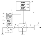
- the liquid chromatograph 1 includes a liquid feeding system 2, a sample injection unit 4, a separation column 6, a detector 8, and a control device 10.
- the liquid feed system 2 includes a liquid feed pump 14 that feeds the mobile phase in the analysis flow path 12 and a pressure sensor 16 for detecting the liquid feed pressure by the liquid feed pump 14. Although only one liquid feeding pump 14 is shown here, two or more liquid feeding pumps may be provided. A mixer 18 is provided after the pressure sensor 16, and the mobile phase fed by the liquid feed pump 14 is mixed in the mixer 18.
- the liquid feed pump 14 has, for example, two plunger pumps that are driven complementarily to each other and continuously feeds liquid.
- a liquid feeding defect that causes instability of the liquid feeding flow rate occurs due to air bubbles entering the pump chamber of the plunger pump.
- the liquid feeding system 2 includes a damper capacity determining unit 20, a damper capacity holding unit 22, a reference value determining unit 24, and a liquid feeding defect detecting unit 26 as functions for detecting the occurrence of a liquid feeding defect by the liquid feeding pump 14. It is provided.
- the damper capacity determination unit 20, the reference value determination unit 24, and the liquid feed defect detection unit 26 are functions obtained by executing a predetermined program in a computer circuit constituting a part of the liquid feed system 2.
- the damper capacity holding unit 22 is a function realized by a part of the storage area of the storage device provided in the liquid feeding system 2. Details of the damper capacity determination unit 20, the damper capacity holding unit 22, the reference value determination unit 24, and the liquid feed defect detection unit 26 will be described later.
- the sample injection unit 4 is provided downstream of the mixer 18 on the analysis flow path 12.
- the sample injection unit 4 is for injecting a sample into the analysis flow path 12.
- the sample injection unit 4 is for switching between a sample loop that temporarily holds the sample (not shown), a first state in which the sample loop is inserted in the analysis flow path 12, and a second state in which the sample loop is not inserted.
- a switching valve 28 is provided, and the sample is injected into the analysis flow path 12 by switching to the first state while holding the sample in the sample loop. Further, the switching valve 28 is configured to be able to switch to a third state for discharging the mobile phase from the liquid feeding system 2 to the drain.
- the switching valve 28 does not necessarily have to have a function of switching to a third state for discharging the mobile phase from the liquid feeding system 2 to the drain.
- a switching valve for switching whether the mobile phase from the liquid feeding system 2 flows to the separation column 6 side or is discharged to the drain may be provided separately from the sample injection unit 4. Further, a switching valve having such a function does not necessarily have to be provided.
- the separation column 6 is provided on the analysis flow path 12 downstream of the sample injection section 4, and the detector 8 is provided further downstream of the separation column 6.
- the separation column 6 is for separating the sample injected into the analysis flow path 12 by the sample injection unit 4 for each component, and the sample component separated by the separation column 6 is detected by the detector 8.
- the control device 10 is for at least managing the operation of the liquid feeding system 2 and the sample injection unit 4, and is realized by, for example, a system controller dedicated to this liquid chromatograph and / or a general-purpose personal computer.
- a signal indicating that the liquid feeding defect is detected is transmitted to the control device 10.
- the control device 10 commands the sample injection unit 4 to switch the switching valve 28 to the third state when it is preset to execute the purge operation for eliminating the liquid feeding failure. Is transmitted, and a command is transmitted to the liquid feeding system 2 to increase the liquid feeding flow rate to a predetermined high flow rate. As a result, the air bubbles mixed in the liquid feed pump 14 are discharged to the drain.
- control device 10 includes a capacity information holding unit 30 and a component specifying unit 32.
- the capacity information holding unit 30 is a function realized by a part of the storage area of the storage device provided in the control device 10, and the component specifying unit 32 is obtained by executing a predetermined program in the control device 10. This is the function that can be obtained.
- the capacity information holding unit 30 contains information on the internal capacity of each element that can form the system through which the mobile phase from the liquid feed pump 14 flows, that is, the analysis flow path 12. It is being held.
- Elements that can constitute the analysis flow path 12 include, for example, a liquid feed pump 14, a pipe (including a pressure sensor 16) from the outlet of the liquid feed pump 14 to the inlet of the mixer 18, the mixer 18, and the outlet of the mixer 18. From the pipe to the inlet of the sample injection unit 4, the inlet and outlet pipes in the sample injection unit 4, the sample loop for temporarily holding the sample in the sample injection unit 4, and the outlet of the sample injection unit 4.
- the piping to the inlet of the separation column 6, the separation column 6 and the like are included.
- the component specifying unit 32 acquires information on the system configuration from the capacity information holding unit 30, and also acquires information on the configuration state of the analysis flow path 12 from elements such as the sample injection unit 4, so that the current analysis flow path 12 is present. It is configured to identify the components.
- the component specifying unit 32 includes the sample loop in the component of the analysis flow path 12 when the sample injection unit 4 is in the first state, and the sample injection unit 4 is in the second state. When the sample loop is excluded from the components of the analysis flow path 12.
- the damper capacity determining unit 20 of the liquid feeding system 2 acquires information on the internal capacity of the components of the analysis flow path 12 specified by the component specifying unit 32 from the capacity information holding unit 30, and totals the internal volumes thereof. As a result, the internal capacity of the system through which the mobile phase from the liquid feed pump 14 flows is determined as the damper capacity.
- the internal capacities of the components of the analysis flow path 12 may be simply added, but the degree of contribution to the compression of the mobile phase depending on the location where each component is provided is taken into consideration. Then, a predetermined coefficient may be multiplied by the internal capacitance of each component and then added together.
- the damper capacity determined by the damper capacity determining unit 20 is held by the damper capacity holding unit 22.
- the damper capacity held by the damper capacity holding unit 22 is used for determining the reference value by the reference value determining unit 24. Further, the control device 10 can be provided with the function of the damper capacity determining unit 20. In that case, the damper capacity determined by the control device 10 is notified to the liquid feeding system 2 and held by the damper capacity holding unit 22.
- the liquid feed pump 14 When the liquid feed pump 14 is able to stably feed the mobile phase, as shown on the left side of the pressure waveform in FIG. 4, the liquid feed pressure has slight pressure fluctuations due to the operation of the liquid feed pump and the like. Things are stable.
- the liquid feed pressure When air bubbles are mixed in one of the plunger pumps of the liquid transfer pump 14, the liquid is not discharged normally due to the compression of the generated air bubbles during the discharge operation of the plunger pump, the liquid transfer pressure drops sharply, and the other plunger pumps. During the discharge operation of the pump, the liquid is discharged normally and the liquid feeding pressure rises. Therefore, as shown on the right side of the pressure waveform in FIG. 4, periodic fluctuation (pulsation) of the liquid feeding pressure occurs. Therefore, the liquid feeding defect detecting unit 26 is configured to detect the liquid feeding defect by detecting the pulsation synchronized with the drive cycle of the liquid feeding pump 14.
- the cycle of the pulsation of the liquid feeding pressure caused by the mixing of air bubbles in the liquid feeding pump 14 is synchronized with the driving cycle of the liquid feeding pump 14 mixed with air bubbles. Therefore, in order to detect the pulsation, it is necessary to capture the signal of the pressure sensor 16 at such a frequency that the fluctuation of the liquid feeding pressure within one drive cycle of the liquid feeding pump 14 can be read. Therefore, the frequency with which the computer circuit constituting the liquid feeding defect detecting unit 26 takes in the signal from the pressure sensor 16 may be adjusted according to the driving speed of the liquid feeding pump 14. In that case, the cycle of reading the signal from the pressure sensor 16 can be determined by calculation when the liquid feed flow rate is determined.
- the liquid feed defect detection unit 26 obtains the fluctuation range of the liquid feed pressure within a constant drive cycle of the liquid feed pump 14, and compares the fluctuation range with the reference value determined by the reference value determination unit 24 to obtain pulsation. It is configured to detect.
- the reference value determining unit 24 is configured to determine a reference value of the fluctuation range of the liquid feeding pressure used for detecting pulsation by using at least the damper capacity held in the damper capacity holding unit 22. ..
- the fluctuation width ⁇ P of the liquid feeding pressure caused by the bubbles mixed in the liquid feeding pump 14 is determined by the time constant ⁇ of the liquid chromatograph, and the time constant ⁇ is the total liquid feeding pressure P [MPa] and the damper C [ It is a value that depends on [uL / MPa] and the liquid feed flow rate Q [mL / min].
- the damper C [uL / MPa] can be obtained by multiplying the damper capacity V [uL] held by the damper capacity holding unit 22 by the compressibility ⁇ [GPa -1 ] of the mobile phase.
- the reference value for determining whether or not the pulsation is caused by the mixing of air bubbles in the liquid feed pump 14 can be determined in consideration of ⁇ P obtained by the above equation.
- the reference value may be determined more simply by omitting some of the arguments P, C, Q, t (or P, V, ⁇ , Q, t) in the above equation.
- ⁇ P obtained with only P and C as arguments and other elements as fixed values may be used as a reference.
- the example of FIG. 2 is advantageous when the fluctuation of the liquid feeding pressure within one drive cycle of the liquid feeding pump 14 can be read in several tens of divisions.
- the liquid feed pressure at the start point and the end point of the discharge operation of each plunger pump of the liquid feed pump 14 can be accurately read.
- the one drive cycle of the liquid feed pump 14 means that the discharge operation of the other plunger pump ends from the time when the discharge operation of one of the plunger pumps constituting the liquid feed pump 14 starts. Up to the point in time.
- the computer circuit constituting the reference value determining unit 24 and the liquid feeding defect detecting unit 26 takes in the signal of the pressure sensor 16 at a predetermined frequency and reads the liquid feeding pressure (moving average value).
- the reference value determination unit 24 and the liquid feed defect detection unit 26 execute the following steps 101 to 108.
- the reference value determination unit 24 determines the reference value using the read liquid feed pressure and the damper capacity held in the damper capacity holding unit 22 (step 101). After that, when the liquid feed defect detection unit 26 reads the liquid feed pressure at the start point and the end point of the discharge operation of one of the plunger pumps constituting the liquid feed pump 14, the difference between them (start). When the liquid feed pressure at the point-the liquid feed pressure at the end point) is obtained as the first fluctuation value (step 102) and the liquid feed pressures at the start and end points of the discharge operation of the other plunger pump are read, they are found. The difference (liquid feeding pressure at the start point-liquid feeding pressure at the ending point) is obtained as the second fluctuation value (step 103).
- the liquid feed pressure drops during the discharge operation of one of the plunger pumps in which the air bubbles are mixed, and the air bubbles are mixed. Since the liquid feed pressure rises during the discharge operation of the other plunger pump, if the liquid feed pump 14 has a liquid feed defect due to the mixing of air bubbles, the first fluctuation value and the second fluctuation value Only one of them has a positive value (the other has a negative value). Therefore, when the signs of the first fluctuation value and the second fluctuation value are the same, the liquid feed defect detection unit 26 determines that the pulsation is not caused by the mixing of air bubbles (step 104).
- the liquid feed defect detection unit 26 uses the first fluctuation value and the second fluctuation value to perform one drive cycle of the liquid feed pump 14.
- the fluctuation range of the liquid feeding pressure in the inside is obtained (step 105).
- Or fluctuation range (first fluctuation value-second fluctuation value) 2
- the fluctuation range may be obtained by using an equation such as.
- the liquid feed defect detection unit 26 compares the above fluctuation value with the reference value determined by the reference value determination unit 24 (step 106), and if the fluctuation value exceeds the reference value, the fluctuation value is the reference value. The number of consecutive drive cycles (fluctuation cycles) exceeding the above is counted (step 107). Then, when the number of continuous fluctuation cycles reaches a predetermined reference number, the pulsation is detected (step 108).
- the reference number of times which is the reference for the number of continuous pressure fluctuations for determining pulsation, may be configured to be variably adjustable. Then, the reference number of times can be adjusted depending on how sensitive the pulsation detection is.
- the algorithm for detecting pulsation is not limited to the above.
- the liquid feeding pressure of the liquid feeding pump 14 is monitored for each driving cycle, the fluctuation range of the liquid feeding pressure within one driving cycle is obtained, and the fluctuation range is compared with the reference value determined by the reference value determining unit 24. By doing so, pulsation can be detected.
- the above algorithm is effective when it is not possible to accurately read the liquid feed pressure at the start point and end point of the discharge operation of each plunger pump constituting the liquid feed pump 14.
- the trigger detection algorithm as shown in the flowchart of FIG. 3 may be introduced before executing the pulsation detection algorithm.
- the computer circuit constituting the reference value determining unit 24 and the liquid feeding defect detecting unit 26 reads the signal of the pressure sensor 16 at a predetermined cycle (step 201) and calculates the liquid feeding pressure (moving average value) (step 202). ..
- the reference value determining unit 24 determines a reference value for trigger detection using the read liquid feed pressure and the damper capacity held in the damper capacity holding unit 22 (step 203).
- the reference value for trigger detection may be the same as or different from the reference value for pulsation detection.
- the liquid feed defect detection unit 26 calculates the drop width of the liquid feed pressure per time (for example, for 10 signal readings) set based on the drive cycle of the liquid feed pump 14 (step 204). Then, the calculated descent width is compared with the reference value determined by the reference value determining unit 24 (step 205), and when the descent width exceeds the reference value, it is detected as a trigger for pulsation generation (step 206).
- the liquid feeding failure detection unit 26 After detecting the trigger, the liquid feeding failure detection unit 26 detects the pulsation by using the above-mentioned pulsation detection algorithm (step 207). When pulsation is detected, poor liquid feeding is detected (steps 208 and 209), and a warning signal is transmitted to the control device 10 (step 210). If no pulsation is detected, the process returns to step 201 (step 208).
- the coefficient for determining the signal reading cycle from the pressure sensor 16, the reference value for trigger detection, and the reference value for pulsation detection by calculation can be obtained by inputting a change instruction by the user or by actually sending the coefficient. It may be configured to be variably adjusted based on the user's evaluation of the result of detecting the liquid defect.
- the liquid chromatograph analysis system is connected to a database common to other liquid chromatograph analysis systems via a network line such as an internet line, the user's evaluation of the detection result of liquid transfer failure accumulated in the database.
- Each of the above coefficients may be automatically adjusted based on the above.
- the sample injection unit 4 injects a sample into the mobile phase
- a sudden drop in liquid feed pressure may occur due to a change in the flow path configuration by the switching valve.
- the liquid feeding failure detecting unit 26 does not detect the pulsation. , It will not be erroneously detected as a liquid transfer failure due to the inclusion of air bubbles.
- the liquid feeding pressure may drop due to a change in the composition of the mobile phase, but even in this case, since the liquid feeding pressure does not change periodically, the liquid feeding defect detection unit 26 Does not detect pulsation and is not erroneously detected as a liquid feeding failure due to the inclusion of air bubbles.
- the liquid feeding system 2 is provided with the functions of the damper capacity determining unit 20, the damper capacity holding unit 22, the reference value determining unit 24, and the liquid feeding defect detecting unit 26.
- the control device 10 is not limited to this, and some or all of these functions may be provided in the control device 10.
- Embodiments of the liquid chromatograph according to the present invention are as follows.
- An embodiment of the liquid chromatograph according to the present invention includes a liquid feed pump for feeding a mobile phase, a sample injection unit for injecting a sample into an analysis flow path through which a mobile phase flows from the liquid feed pump, and the above.
- a separation column provided on the analysis flow path for separating the sample injected into the analysis flow path by the sample injection unit for each component, and a liquid feed pressure in the analysis flow path upstream of the separation column.
- At least the pressure sensor for detecting the pressure, the damper capacity holding unit that holds the internal capacity of the system through which the mobile phase from the liquid feed pump flows as the damper capacity, and the damper capacity held by the damper capacity holding unit are used.
- the reference value determining unit configured to determine the reference value of the fluctuation range of the liquid feeding pressure when the liquid feeding failure of the liquid feeding pump occurs, and the liquid feeding pressure detected by the pressure sensor. It is taken in periodically, the fluctuation range of the liquid feed pressure within the constant drive cycle of the liquid feed pump is obtained, and the liquid feed failure is performed using the obtained fluctuation range and the reference value determined by the reference value determination unit. It is equipped with a liquid feeding defect detection unit configured to detect.
- a capacitance information holding unit that holds information on the internal capacitance of each of a plurality of elements that can constitute a system through which the mobile phase from the liquid feeding pump flows
- the component specifying unit configured to specify the component of the system through which the mobile phase from the liquid feed pump flows and the component specified by the component specifying unit are held by the capacitance information holding unit.
- a damper capacity determining unit configured to determine the damper capacity using an internal capacity is provided, and the damper capacity holding unit is configured to hold the damper capacity determined by the damper capacity determining unit.
- the sample injection unit has a sample loop that temporarily holds the sample, and can be switched between a first state in which the sample loop is inserted into the analysis flow path and a second state in which the sample loop is not inserted.
- the capacity information holding unit holds the internal capacity of the sample loop
- the component specifying unit is the sample loop when the sample injection unit is in the first state. May be included in the component, and the sample loop may be excluded from the component when the sample injection unit is in the second state.
- the liquid feeding defect detection unit has a predetermined number of consecutive cycles in which the fluctuation range exceeds the reference value determined by the reference value determination unit.
- a pulsation detection step that detects a pulsation on condition that the reference number of times has been exceeded, and a liquid supply failure detection step that detects a liquid supply failure of the liquid supply pump when the pulsation is detected in the pulsation detection step. It is configured to run in that order. According to such an aspect, pulsation caused by the inclusion of air bubbles in the liquid feed pump can be detected.
- the liquid feed pump is a double plunger pump including two plunger pumps that are driven complementarily to each other, and the liquid feed defect detection unit is used in the pulsation detection step.
- the difference in the liquid feeding pressure between the start point and the end point of the discharge operation of one of the two plunger pumps is obtained as the first fluctuation value, and the start point of the discharge operation of the other of the two plunger pumps is obtained.
- the difference between the liquid feeding pressure and the end point is obtained as the second fluctuation value, and the fluctuation range is obtained by using the first fluctuation value and the second fluctuation value.
- the fluctuation of the liquid feed pressure during the discharge operation of one of the plunger pumps of the liquid feed pump and the fluctuation of the liquid feed pressure during the discharge operation of the other plunger pump are taken into consideration for the pulsation. Since the detection can be performed, the pulsation caused by the mixing of air bubbles can be detected more accurately.
- the liquid feeding defect detection unit performs only a cycle in which only one of the first fluctuation value and the second fluctuation value is a positive value in the pulsation detection step.
- An example is given in which the fluctuation range is counted as a period exceeding the reference value determined by the reference value determination unit.
- the liquid feed pressure drops during the discharge operation of one plunger pump and rises during the discharge operation of the other plunger pump.
- the first fluctuation value and the second fluctuation value have different reference numerals. Therefore, the pulsation can be detected more accurately by counting only the cycle in which only one of the first fluctuation value and the second fluctuation value is a positive value as one cycle of the pulsation.
- the liquid feed defect detecting unit calculates the drop width of the liquid feed pressure per time set based on the drive cycle of the liquid feed pump before the pulsation detection step.
- the pressure drop calculation step and the trigger detection step of detecting as a trigger of pulsation generation when the drop width calculated in the pressure drop calculation step exceeds the reference value determined by the reference value determination unit are executed, and the above-mentioned
- the pulsation determination step may be executed after the trigger is detected in the trigger detection step.
- Liquid chromatograph 1 Liquid chromatograph 2 Liquid feeding system 4 Sample injection part 6 Separation column 8 Detector 10 Control device 12 Analysis flow path 14 Liquid feeding pump 16 Pressure sensor 18 Mixer 20 Damper capacity determination unit 22 Damper capacity holding unit 24 Reference value determination unit 26 Liquid supply failure detection unit 28 Switching valve 30 Capacity information holding unit 32 Component identification unit
Landscapes
- Physics & Mathematics (AREA)
- Health & Medical Sciences (AREA)
- Life Sciences & Earth Sciences (AREA)
- Chemical & Material Sciences (AREA)
- Analytical Chemistry (AREA)
- Biochemistry (AREA)
- General Health & Medical Sciences (AREA)
- General Physics & Mathematics (AREA)
- Immunology (AREA)
- Pathology (AREA)
- Engineering & Computer Science (AREA)
- Library & Information Science (AREA)
- Control Of Positive-Displacement Pumps (AREA)
Abstract
La présente invention concerne un chromatographe en phase liquide (1) qui comprend : une pompe d'alimentation en liquide (14) pour alimenter en un liquide en tant que phase mobile; une partie d'injection d'échantillon (4) pour injecter un échantillon dans un canal d'écoulement d'analyse (12) à travers lequel s'écoule la phase mobile provenant de la pompe d'alimentation en liquide (14); une colonne de séparation (6) qui est disposée sur le canal d'écoulement d'analyse (12) et qui est destinée à séparer, en constituants, l'échantillon injecté par la partie d'injection d'échantillon (4) dans le canal d'écoulement d'analyse (12); un capteur de pression (16) pour détecter la pression du liquide qui est alimenté, sur le côté amont à partir de la colonne de séparation (6), dans le canal d'écoulement d'analyse (12); une unité de maintien de capacité d'amortisseur (22) pour maintenir, en tant que capacité d'amortisseur, la capacité interne d'un système dans lequel s'écoule la phase mobile provenant de la pompe d'alimentation en liquide (14); une unité de détermination de valeur de référence (24) conçue pour déterminer une valeur de référence pour la plage de variation de la pression du liquide qui est alimenté à un moment où une défaillance d'alimentation en liquide s'est produite dans la pompe d'alimentation en liquide (14), en utilisant au moins la capacité d'amortisseur maintenue par l'unité de maintien de capacité d'amortisseur (22); et une unité de détection de défaillance d'alimentation en liquide (26) conçue pour obtenir de manière cyclique la pression du liquide alimenté, détectée par le capteur de pression (16), calculer la plage de variation de la pression du liquide qui est alimenté dans un cycle d'entraînement prescrit de la pompe d'alimentation en liquide (14), et détecter une défaillance d'alimentation en liquide à l'aide de la plage de variation calculée et de la valeur de référence déterminée par l'unité de détermination de valeur de référence (24).
Priority Applications (4)
| Application Number | Priority Date | Filing Date | Title |
|---|---|---|---|
| CN201980093712.3A CN113544503B (zh) | 2019-03-13 | 2019-03-13 | 液相色谱仪 |
| US17/438,419 US12007373B2 (en) | 2019-03-13 | 2019-03-13 | Liquid chromatograph |
| PCT/JP2019/010420 WO2020183684A1 (fr) | 2019-03-13 | 2019-03-13 | Chromatographe en phase liquide |
| JP2021504739A JP7120438B2 (ja) | 2019-03-13 | 2019-03-13 | 液体クロマトグラフ |
Applications Claiming Priority (1)
| Application Number | Priority Date | Filing Date | Title |
|---|---|---|---|
| PCT/JP2019/010420 WO2020183684A1 (fr) | 2019-03-13 | 2019-03-13 | Chromatographe en phase liquide |
Publications (1)
| Publication Number | Publication Date |
|---|---|
| WO2020183684A1 true WO2020183684A1 (fr) | 2020-09-17 |
Family
ID=72426978
Family Applications (1)
| Application Number | Title | Priority Date | Filing Date |
|---|---|---|---|
| PCT/JP2019/010420 WO2020183684A1 (fr) | 2019-03-13 | 2019-03-13 | Chromatographe en phase liquide |
Country Status (4)
| Country | Link |
|---|---|
| US (1) | US12007373B2 (fr) |
| JP (1) | JP7120438B2 (fr) |
| CN (1) | CN113544503B (fr) |
| WO (1) | WO2020183684A1 (fr) |
Cited By (2)
| Publication number | Priority date | Publication date | Assignee | Title |
|---|---|---|---|---|
| WO2023106033A1 (fr) * | 2021-12-10 | 2023-06-15 | 株式会社日立ハイテク | Procédé de commande de chromatographe en phase liquide |
| WO2023218758A1 (fr) * | 2022-05-12 | 2023-11-16 | 株式会社島津製作所 | Système de distribution de liquide de chromatographe et procédé de distribution de liquide de chromatographe |
Citations (5)
| Publication number | Priority date | Publication date | Assignee | Title |
|---|---|---|---|---|
| JPS63106382A (ja) * | 1986-06-19 | 1988-05-11 | Shimadzu Corp | 送液ポンプ |
| JPH01182579A (ja) * | 1988-01-14 | 1989-07-20 | Hitachi Ltd | 低脈流ポンプ装置 |
| JP2000130353A (ja) * | 1998-10-30 | 2000-05-12 | Shimadzu Corp | 送液ポンプ |
| JP2004507639A (ja) * | 2000-08-21 | 2004-03-11 | ウォーターズ・インヴェストメンツ・リミテッド | 液体ポンプシステムにおける気泡検出および回復 |
| US20160327514A1 (en) * | 2015-05-08 | 2016-11-10 | Agilent Technologies, Inc. | Correcting sample metering inaccuracy due to thermally induced volume change in sample separation apparatus |
Family Cites Families (15)
| Publication number | Priority date | Publication date | Assignee | Title |
|---|---|---|---|---|
| JPS5910064U (ja) * | 1982-06-29 | 1984-01-21 | 株式会社島津製作所 | 液体クロマトグラフの送液装置 |
| CA1186166A (fr) | 1982-02-27 | 1985-04-30 | Katsuhiko Saito | Chromatographe a liquide |
| JPS6011690A (ja) | 1983-06-30 | 1985-01-21 | Shimadzu Corp | 液体クロマトグラフ |
| JP2833130B2 (ja) * | 1990-03-30 | 1998-12-09 | 株式会社島津製作所 | 高速液体クロマトグラフ |
| JPH0915221A (ja) * | 1995-06-29 | 1997-01-17 | Shimadzu Corp | 液体クロマトグラフ装置 |
| JPH11326300A (ja) | 1998-05-20 | 1999-11-26 | Shimadzu Corp | 液体クロマトグラフ |
| JP4092831B2 (ja) | 1999-11-24 | 2008-05-28 | 株式会社島津製作所 | 送液装置 |
| US6635173B2 (en) | 2000-12-28 | 2003-10-21 | Cohesive Technologies, Inc. | Multi column chromatography system |
| US7241115B2 (en) | 2002-03-01 | 2007-07-10 | Waters Investments Limited | Methods and apparatus for determining the presence or absence of a fluid leak |
| DE112005001172T5 (de) | 2004-05-21 | 2008-07-17 | Waters Investments Ltd., New Castle | Flusskreislaufsteuerung einer HPLC-Pumpe mit konstantem Fluss, um einen Niedrigflussbetrieb zu ermöglichen |
| JP2006126089A (ja) * | 2004-10-29 | 2006-05-18 | Hitachi High-Technologies Corp | 送液ポンプ装置 |
| US10054569B2 (en) | 2010-10-29 | 2018-08-21 | Thermo Finnigan Llc | Method and system for liquid chromatography fluidic monitoring |
| US9243619B2 (en) | 2011-09-13 | 2016-01-26 | Seiko Epson Corporation | Liquid feed pump and circulation pump with detection units to detect operating states of the pumps |
| JP6367195B2 (ja) | 2013-07-17 | 2018-08-01 | 積水メディカル株式会社 | 試料分析装置におけるグラジエント送液装置 |
| JP6696578B2 (ja) | 2016-09-26 | 2020-05-20 | 株式会社島津製作所 | 切替バルブ、バイナリポンプ及びそのバイナリポンプを備えた液体クロマトグラフ |
-
2019
- 2019-03-13 CN CN201980093712.3A patent/CN113544503B/zh active Active
- 2019-03-13 US US17/438,419 patent/US12007373B2/en active Active
- 2019-03-13 WO PCT/JP2019/010420 patent/WO2020183684A1/fr active Application Filing
- 2019-03-13 JP JP2021504739A patent/JP7120438B2/ja active Active
Patent Citations (5)
| Publication number | Priority date | Publication date | Assignee | Title |
|---|---|---|---|---|
| JPS63106382A (ja) * | 1986-06-19 | 1988-05-11 | Shimadzu Corp | 送液ポンプ |
| JPH01182579A (ja) * | 1988-01-14 | 1989-07-20 | Hitachi Ltd | 低脈流ポンプ装置 |
| JP2000130353A (ja) * | 1998-10-30 | 2000-05-12 | Shimadzu Corp | 送液ポンプ |
| JP2004507639A (ja) * | 2000-08-21 | 2004-03-11 | ウォーターズ・インヴェストメンツ・リミテッド | 液体ポンプシステムにおける気泡検出および回復 |
| US20160327514A1 (en) * | 2015-05-08 | 2016-11-10 | Agilent Technologies, Inc. | Correcting sample metering inaccuracy due to thermally induced volume change in sample separation apparatus |
Cited By (2)
| Publication number | Priority date | Publication date | Assignee | Title |
|---|---|---|---|---|
| WO2023106033A1 (fr) * | 2021-12-10 | 2023-06-15 | 株式会社日立ハイテク | Procédé de commande de chromatographe en phase liquide |
| WO2023218758A1 (fr) * | 2022-05-12 | 2023-11-16 | 株式会社島津製作所 | Système de distribution de liquide de chromatographe et procédé de distribution de liquide de chromatographe |
Also Published As
| Publication number | Publication date |
|---|---|
| US12007373B2 (en) | 2024-06-11 |
| JPWO2020183684A1 (ja) | 2021-12-16 |
| CN113544503A (zh) | 2021-10-22 |
| JP7120438B2 (ja) | 2022-08-17 |
| CN113544503B (zh) | 2024-02-06 |
| US20220146474A1 (en) | 2022-05-12 |
Similar Documents
| Publication | Publication Date | Title |
|---|---|---|
| US9170187B2 (en) | Flow cytometer and fluidic system thereof | |
| US7694591B2 (en) | Method and apparatus for evaluating a dosing operation | |
| WO2020183684A1 (fr) | Chromatographe en phase liquide | |
| US7644632B2 (en) | Viscometric flowmeter | |
| WO2019211930A1 (fr) | Échantillonneur automatique et chromatographe en phase liquide | |
| US10364808B2 (en) | Pumping system for chromatography applications | |
| JP7226525B2 (ja) | 液体クロマトグラフ用送液システム | |
| US20180306682A1 (en) | Smart pump for a portable gas detection instrument | |
| JP7226524B2 (ja) | 液体クロマトグラフ用送液システム | |
| JP7226523B2 (ja) | 液体クロマトグラフ分析システム | |
| US10900937B2 (en) | Continuous and separating gas analysis | |
| JP7260063B2 (ja) | 液体クロマトグラフィ分析システム | |
| JP2006126089A (ja) | 送液ポンプ装置 | |
| WO2022064012A1 (fr) | Surveillance de fonctionnement de systèmes analytiques fluidiques in situ | |
| JP2024035932A (ja) | イオンクロマトグラフィ分析システム |
Legal Events
| Date | Code | Title | Description |
|---|---|---|---|
| 121 | Ep: the epo has been informed by wipo that ep was designated in this application |
Ref document number: 19919393 Country of ref document: EP Kind code of ref document: A1 |
|
| ENP | Entry into the national phase |
Ref document number: 2021504739 Country of ref document: JP Kind code of ref document: A |
|
| NENP | Non-entry into the national phase |
Ref country code: DE |
|
| 122 | Ep: pct application non-entry in european phase |
Ref document number: 19919393 Country of ref document: EP Kind code of ref document: A1 |