WO2020183684A1 - Liquid chromatograph - Google Patents
Liquid chromatograph Download PDFInfo
- Publication number
- WO2020183684A1 WO2020183684A1 PCT/JP2019/010420 JP2019010420W WO2020183684A1 WO 2020183684 A1 WO2020183684 A1 WO 2020183684A1 JP 2019010420 W JP2019010420 W JP 2019010420W WO 2020183684 A1 WO2020183684 A1 WO 2020183684A1
- Authority
- WO
- WIPO (PCT)
- Prior art keywords
- liquid
- liquid feeding
- unit
- reference value
- pressure
- Prior art date
Links
Images


Classifications
-
- G—PHYSICS
- G01—MEASURING; TESTING
- G01N—INVESTIGATING OR ANALYSING MATERIALS BY DETERMINING THEIR CHEMICAL OR PHYSICAL PROPERTIES
- G01N30/00—Investigating or analysing materials by separation into components using adsorption, absorption or similar phenomena or using ion-exchange, e.g. chromatography or field flow fractionation
- G01N30/02—Column chromatography
- G01N30/86—Signal analysis
- G01N30/8675—Evaluation, i.e. decoding of the signal into analytical information
-
- G—PHYSICS
- G01—MEASURING; TESTING
- G01N—INVESTIGATING OR ANALYSING MATERIALS BY DETERMINING THEIR CHEMICAL OR PHYSICAL PROPERTIES
- G01N30/00—Investigating or analysing materials by separation into components using adsorption, absorption or similar phenomena or using ion-exchange, e.g. chromatography or field flow fractionation
- G01N30/02—Column chromatography
- G01N30/26—Conditioning of the fluid carrier; Flow patterns
- G01N30/28—Control of physical parameters of the fluid carrier
- G01N30/32—Control of physical parameters of the fluid carrier of pressure or speed
-
- G—PHYSICS
- G01—MEASURING; TESTING
- G01N—INVESTIGATING OR ANALYSING MATERIALS BY DETERMINING THEIR CHEMICAL OR PHYSICAL PROPERTIES
- G01N30/00—Investigating or analysing materials by separation into components using adsorption, absorption or similar phenomena or using ion-exchange, e.g. chromatography or field flow fractionation
- G01N30/02—Column chromatography
- G01N2030/022—Column chromatography characterised by the kind of separation mechanism
- G01N2030/027—Liquid chromatography
-
- G—PHYSICS
- G01—MEASURING; TESTING
- G01N—INVESTIGATING OR ANALYSING MATERIALS BY DETERMINING THEIR CHEMICAL OR PHYSICAL PROPERTIES
- G01N30/00—Investigating or analysing materials by separation into components using adsorption, absorption or similar phenomena or using ion-exchange, e.g. chromatography or field flow fractionation
- G01N30/02—Column chromatography
- G01N30/26—Conditioning of the fluid carrier; Flow patterns
- G01N30/28—Control of physical parameters of the fluid carrier
- G01N30/32—Control of physical parameters of the fluid carrier of pressure or speed
- G01N2030/322—Control of physical parameters of the fluid carrier of pressure or speed pulse dampers
Definitions
- the present invention relates to a liquid chromatograph.
- the liquid transfer system for liquid chromatographs is required to have the ability to stably transfer the solvent that becomes the mobile phase at a set flow rate.
- a single plunger system equipped with a single plunger pump and a double plunger system equipped with two plunger pumps are adopted.
- the gas component remaining in the solvent may become bubbles in the plunger pump, or the dissolved oxygen in the solvent may be saturated due to temperature changes to generate bubbles. For this reason, air bubbles may be mixed in the plunger pump during liquid transfer, and the analysis may be continued as it is. In such a case, the user will continue to collect useless analytical data.
- the sample injection section, the separation column, the detector, and the piping connecting them which constitute the analysis system of the liquid chromatograph, each have an internal capacity.
- their internal volumes act as dampers and affect the magnitude of fluctuations in liquid feeding pressure when a liquid feeding failure occurs in the liquid feeding pump. Since the size of the internal capacity that acts as a damper differs depending on the number and type of elements that make up the analysis system, it is necessary to accurately detect liquid feeding defects by evaluating the magnitude of fluctuations in liquid feeding pressure using a single standard. I can't.
- the present invention has been made in view of the above problems, and an object of the present invention is to enable accurate detection of a liquid feeding defect of a liquid feeding pump.
- the liquid chromatograph includes a liquid feed pump for feeding a mobile phase, a sample injection section for injecting a sample into an analysis flow path through which the mobile phase flows from the liquid feed pump, and an analysis flow path.
- a separation column for separating each component of the sample injected into the analysis flow path by the sample injection unit, and a liquid feeding pressure in the analysis flow path upstream of the separation column are detected.
- a pressure sensor for the purpose, a damper capacity holding portion that holds the internal capacity of the system through which the mobile phase from the liquid feed pump flows as a damper capacity, and the damper capacity held by the damper capacity holding portion are used at least to describe the above.
- a reference value determining unit configured to determine a reference value of the fluctuation range of the liquid feeding pressure when a liquid feeding failure of the liquid feeding pump occurs, and a liquid feeding pressure detected by the pressure sensor periodically.
- the fluctuation range of the liquid feed pressure within a constant drive cycle of the liquid feed pump is obtained, and the liquid feed defect is detected by using the obtained fluctuation range and the reference value determined by the reference value determination unit. It is equipped with a liquid feeding defect detection unit configured as described above.
- the "fluctuation width of the liquid feed pressure within a constant drive cycle of the liquid feed pump” may be the fluctuation range of the liquid feed pressure within one drive cycle of the liquid feed pump. However, it may be the average value of the fluctuation range of the liquid feed pressure within the plurality of drive cycles of the liquid feed pump or the fluctuation range of the liquid feed pressure within the multiple drive cycles of the liquid feed pump.
- the internal capacity of the system through which the mobile phase flows from the liquid feed pump is held as the damper capacity, and at least the damper capacity is used to feed the liquid when a liquid feed failure occurs in the liquid feed pump. Since the reference value of the fluctuation range of the liquid pressure is determined and the determined reference value and the fluctuation range of the liquid feed pressure within the constant drive cycle of the liquid feed pump are used to detect the liquid feed failure. Defective liquid feeding is detected using a reference value that takes into account the damper capacity that differs for each analysis system, and defective liquid feeding of the liquid feeding pump can be accurately detected.
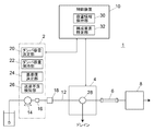
- the liquid chromatograph 1 includes a liquid feeding system 2, a sample injection unit 4, a separation column 6, a detector 8, and a control device 10.
- the liquid feed system 2 includes a liquid feed pump 14 that feeds the mobile phase in the analysis flow path 12 and a pressure sensor 16 for detecting the liquid feed pressure by the liquid feed pump 14. Although only one liquid feeding pump 14 is shown here, two or more liquid feeding pumps may be provided. A mixer 18 is provided after the pressure sensor 16, and the mobile phase fed by the liquid feed pump 14 is mixed in the mixer 18.
- the liquid feed pump 14 has, for example, two plunger pumps that are driven complementarily to each other and continuously feeds liquid.
- a liquid feeding defect that causes instability of the liquid feeding flow rate occurs due to air bubbles entering the pump chamber of the plunger pump.
- the liquid feeding system 2 includes a damper capacity determining unit 20, a damper capacity holding unit 22, a reference value determining unit 24, and a liquid feeding defect detecting unit 26 as functions for detecting the occurrence of a liquid feeding defect by the liquid feeding pump 14. It is provided.
- the damper capacity determination unit 20, the reference value determination unit 24, and the liquid feed defect detection unit 26 are functions obtained by executing a predetermined program in a computer circuit constituting a part of the liquid feed system 2.
- the damper capacity holding unit 22 is a function realized by a part of the storage area of the storage device provided in the liquid feeding system 2. Details of the damper capacity determination unit 20, the damper capacity holding unit 22, the reference value determination unit 24, and the liquid feed defect detection unit 26 will be described later.
- the sample injection unit 4 is provided downstream of the mixer 18 on the analysis flow path 12.
- the sample injection unit 4 is for injecting a sample into the analysis flow path 12.
- the sample injection unit 4 is for switching between a sample loop that temporarily holds the sample (not shown), a first state in which the sample loop is inserted in the analysis flow path 12, and a second state in which the sample loop is not inserted.
- a switching valve 28 is provided, and the sample is injected into the analysis flow path 12 by switching to the first state while holding the sample in the sample loop. Further, the switching valve 28 is configured to be able to switch to a third state for discharging the mobile phase from the liquid feeding system 2 to the drain.
- the switching valve 28 does not necessarily have to have a function of switching to a third state for discharging the mobile phase from the liquid feeding system 2 to the drain.
- a switching valve for switching whether the mobile phase from the liquid feeding system 2 flows to the separation column 6 side or is discharged to the drain may be provided separately from the sample injection unit 4. Further, a switching valve having such a function does not necessarily have to be provided.
- the separation column 6 is provided on the analysis flow path 12 downstream of the sample injection section 4, and the detector 8 is provided further downstream of the separation column 6.
- the separation column 6 is for separating the sample injected into the analysis flow path 12 by the sample injection unit 4 for each component, and the sample component separated by the separation column 6 is detected by the detector 8.
- the control device 10 is for at least managing the operation of the liquid feeding system 2 and the sample injection unit 4, and is realized by, for example, a system controller dedicated to this liquid chromatograph and / or a general-purpose personal computer.
- a signal indicating that the liquid feeding defect is detected is transmitted to the control device 10.
- the control device 10 commands the sample injection unit 4 to switch the switching valve 28 to the third state when it is preset to execute the purge operation for eliminating the liquid feeding failure. Is transmitted, and a command is transmitted to the liquid feeding system 2 to increase the liquid feeding flow rate to a predetermined high flow rate. As a result, the air bubbles mixed in the liquid feed pump 14 are discharged to the drain.
- control device 10 includes a capacity information holding unit 30 and a component specifying unit 32.
- the capacity information holding unit 30 is a function realized by a part of the storage area of the storage device provided in the control device 10, and the component specifying unit 32 is obtained by executing a predetermined program in the control device 10. This is the function that can be obtained.
- the capacity information holding unit 30 contains information on the internal capacity of each element that can form the system through which the mobile phase from the liquid feed pump 14 flows, that is, the analysis flow path 12. It is being held.
- Elements that can constitute the analysis flow path 12 include, for example, a liquid feed pump 14, a pipe (including a pressure sensor 16) from the outlet of the liquid feed pump 14 to the inlet of the mixer 18, the mixer 18, and the outlet of the mixer 18. From the pipe to the inlet of the sample injection unit 4, the inlet and outlet pipes in the sample injection unit 4, the sample loop for temporarily holding the sample in the sample injection unit 4, and the outlet of the sample injection unit 4.
- the piping to the inlet of the separation column 6, the separation column 6 and the like are included.
- the component specifying unit 32 acquires information on the system configuration from the capacity information holding unit 30, and also acquires information on the configuration state of the analysis flow path 12 from elements such as the sample injection unit 4, so that the current analysis flow path 12 is present. It is configured to identify the components.
- the component specifying unit 32 includes the sample loop in the component of the analysis flow path 12 when the sample injection unit 4 is in the first state, and the sample injection unit 4 is in the second state. When the sample loop is excluded from the components of the analysis flow path 12.
- the damper capacity determining unit 20 of the liquid feeding system 2 acquires information on the internal capacity of the components of the analysis flow path 12 specified by the component specifying unit 32 from the capacity information holding unit 30, and totals the internal volumes thereof. As a result, the internal capacity of the system through which the mobile phase from the liquid feed pump 14 flows is determined as the damper capacity.
- the internal capacities of the components of the analysis flow path 12 may be simply added, but the degree of contribution to the compression of the mobile phase depending on the location where each component is provided is taken into consideration. Then, a predetermined coefficient may be multiplied by the internal capacitance of each component and then added together.
- the damper capacity determined by the damper capacity determining unit 20 is held by the damper capacity holding unit 22.
- the damper capacity held by the damper capacity holding unit 22 is used for determining the reference value by the reference value determining unit 24. Further, the control device 10 can be provided with the function of the damper capacity determining unit 20. In that case, the damper capacity determined by the control device 10 is notified to the liquid feeding system 2 and held by the damper capacity holding unit 22.
- the liquid feed pump 14 When the liquid feed pump 14 is able to stably feed the mobile phase, as shown on the left side of the pressure waveform in FIG. 4, the liquid feed pressure has slight pressure fluctuations due to the operation of the liquid feed pump and the like. Things are stable.
- the liquid feed pressure When air bubbles are mixed in one of the plunger pumps of the liquid transfer pump 14, the liquid is not discharged normally due to the compression of the generated air bubbles during the discharge operation of the plunger pump, the liquid transfer pressure drops sharply, and the other plunger pumps. During the discharge operation of the pump, the liquid is discharged normally and the liquid feeding pressure rises. Therefore, as shown on the right side of the pressure waveform in FIG. 4, periodic fluctuation (pulsation) of the liquid feeding pressure occurs. Therefore, the liquid feeding defect detecting unit 26 is configured to detect the liquid feeding defect by detecting the pulsation synchronized with the drive cycle of the liquid feeding pump 14.
- the cycle of the pulsation of the liquid feeding pressure caused by the mixing of air bubbles in the liquid feeding pump 14 is synchronized with the driving cycle of the liquid feeding pump 14 mixed with air bubbles. Therefore, in order to detect the pulsation, it is necessary to capture the signal of the pressure sensor 16 at such a frequency that the fluctuation of the liquid feeding pressure within one drive cycle of the liquid feeding pump 14 can be read. Therefore, the frequency with which the computer circuit constituting the liquid feeding defect detecting unit 26 takes in the signal from the pressure sensor 16 may be adjusted according to the driving speed of the liquid feeding pump 14. In that case, the cycle of reading the signal from the pressure sensor 16 can be determined by calculation when the liquid feed flow rate is determined.
- the liquid feed defect detection unit 26 obtains the fluctuation range of the liquid feed pressure within a constant drive cycle of the liquid feed pump 14, and compares the fluctuation range with the reference value determined by the reference value determination unit 24 to obtain pulsation. It is configured to detect.
- the reference value determining unit 24 is configured to determine a reference value of the fluctuation range of the liquid feeding pressure used for detecting pulsation by using at least the damper capacity held in the damper capacity holding unit 22. ..
- the fluctuation width ⁇ P of the liquid feeding pressure caused by the bubbles mixed in the liquid feeding pump 14 is determined by the time constant ⁇ of the liquid chromatograph, and the time constant ⁇ is the total liquid feeding pressure P [MPa] and the damper C [ It is a value that depends on [uL / MPa] and the liquid feed flow rate Q [mL / min].
- the damper C [uL / MPa] can be obtained by multiplying the damper capacity V [uL] held by the damper capacity holding unit 22 by the compressibility ⁇ [GPa -1 ] of the mobile phase.
- the reference value for determining whether or not the pulsation is caused by the mixing of air bubbles in the liquid feed pump 14 can be determined in consideration of ⁇ P obtained by the above equation.
- the reference value may be determined more simply by omitting some of the arguments P, C, Q, t (or P, V, ⁇ , Q, t) in the above equation.
- ⁇ P obtained with only P and C as arguments and other elements as fixed values may be used as a reference.
- the example of FIG. 2 is advantageous when the fluctuation of the liquid feeding pressure within one drive cycle of the liquid feeding pump 14 can be read in several tens of divisions.
- the liquid feed pressure at the start point and the end point of the discharge operation of each plunger pump of the liquid feed pump 14 can be accurately read.
- the one drive cycle of the liquid feed pump 14 means that the discharge operation of the other plunger pump ends from the time when the discharge operation of one of the plunger pumps constituting the liquid feed pump 14 starts. Up to the point in time.
- the computer circuit constituting the reference value determining unit 24 and the liquid feeding defect detecting unit 26 takes in the signal of the pressure sensor 16 at a predetermined frequency and reads the liquid feeding pressure (moving average value).
- the reference value determination unit 24 and the liquid feed defect detection unit 26 execute the following steps 101 to 108.
- the reference value determination unit 24 determines the reference value using the read liquid feed pressure and the damper capacity held in the damper capacity holding unit 22 (step 101). After that, when the liquid feed defect detection unit 26 reads the liquid feed pressure at the start point and the end point of the discharge operation of one of the plunger pumps constituting the liquid feed pump 14, the difference between them (start). When the liquid feed pressure at the point-the liquid feed pressure at the end point) is obtained as the first fluctuation value (step 102) and the liquid feed pressures at the start and end points of the discharge operation of the other plunger pump are read, they are found. The difference (liquid feeding pressure at the start point-liquid feeding pressure at the ending point) is obtained as the second fluctuation value (step 103).
- the liquid feed pressure drops during the discharge operation of one of the plunger pumps in which the air bubbles are mixed, and the air bubbles are mixed. Since the liquid feed pressure rises during the discharge operation of the other plunger pump, if the liquid feed pump 14 has a liquid feed defect due to the mixing of air bubbles, the first fluctuation value and the second fluctuation value Only one of them has a positive value (the other has a negative value). Therefore, when the signs of the first fluctuation value and the second fluctuation value are the same, the liquid feed defect detection unit 26 determines that the pulsation is not caused by the mixing of air bubbles (step 104).
- the liquid feed defect detection unit 26 uses the first fluctuation value and the second fluctuation value to perform one drive cycle of the liquid feed pump 14.
- the fluctuation range of the liquid feeding pressure in the inside is obtained (step 105).
- Or fluctuation range (first fluctuation value-second fluctuation value) 2
- the fluctuation range may be obtained by using an equation such as.
- the liquid feed defect detection unit 26 compares the above fluctuation value with the reference value determined by the reference value determination unit 24 (step 106), and if the fluctuation value exceeds the reference value, the fluctuation value is the reference value. The number of consecutive drive cycles (fluctuation cycles) exceeding the above is counted (step 107). Then, when the number of continuous fluctuation cycles reaches a predetermined reference number, the pulsation is detected (step 108).
- the reference number of times which is the reference for the number of continuous pressure fluctuations for determining pulsation, may be configured to be variably adjustable. Then, the reference number of times can be adjusted depending on how sensitive the pulsation detection is.
- the algorithm for detecting pulsation is not limited to the above.
- the liquid feeding pressure of the liquid feeding pump 14 is monitored for each driving cycle, the fluctuation range of the liquid feeding pressure within one driving cycle is obtained, and the fluctuation range is compared with the reference value determined by the reference value determining unit 24. By doing so, pulsation can be detected.
- the above algorithm is effective when it is not possible to accurately read the liquid feed pressure at the start point and end point of the discharge operation of each plunger pump constituting the liquid feed pump 14.
- the trigger detection algorithm as shown in the flowchart of FIG. 3 may be introduced before executing the pulsation detection algorithm.
- the computer circuit constituting the reference value determining unit 24 and the liquid feeding defect detecting unit 26 reads the signal of the pressure sensor 16 at a predetermined cycle (step 201) and calculates the liquid feeding pressure (moving average value) (step 202). ..
- the reference value determining unit 24 determines a reference value for trigger detection using the read liquid feed pressure and the damper capacity held in the damper capacity holding unit 22 (step 203).
- the reference value for trigger detection may be the same as or different from the reference value for pulsation detection.
- the liquid feed defect detection unit 26 calculates the drop width of the liquid feed pressure per time (for example, for 10 signal readings) set based on the drive cycle of the liquid feed pump 14 (step 204). Then, the calculated descent width is compared with the reference value determined by the reference value determining unit 24 (step 205), and when the descent width exceeds the reference value, it is detected as a trigger for pulsation generation (step 206).
- the liquid feeding failure detection unit 26 After detecting the trigger, the liquid feeding failure detection unit 26 detects the pulsation by using the above-mentioned pulsation detection algorithm (step 207). When pulsation is detected, poor liquid feeding is detected (steps 208 and 209), and a warning signal is transmitted to the control device 10 (step 210). If no pulsation is detected, the process returns to step 201 (step 208).
- the coefficient for determining the signal reading cycle from the pressure sensor 16, the reference value for trigger detection, and the reference value for pulsation detection by calculation can be obtained by inputting a change instruction by the user or by actually sending the coefficient. It may be configured to be variably adjusted based on the user's evaluation of the result of detecting the liquid defect.
- the liquid chromatograph analysis system is connected to a database common to other liquid chromatograph analysis systems via a network line such as an internet line, the user's evaluation of the detection result of liquid transfer failure accumulated in the database.
- Each of the above coefficients may be automatically adjusted based on the above.
- the sample injection unit 4 injects a sample into the mobile phase
- a sudden drop in liquid feed pressure may occur due to a change in the flow path configuration by the switching valve.
- the liquid feeding failure detecting unit 26 does not detect the pulsation. , It will not be erroneously detected as a liquid transfer failure due to the inclusion of air bubbles.
- the liquid feeding pressure may drop due to a change in the composition of the mobile phase, but even in this case, since the liquid feeding pressure does not change periodically, the liquid feeding defect detection unit 26 Does not detect pulsation and is not erroneously detected as a liquid feeding failure due to the inclusion of air bubbles.
- the liquid feeding system 2 is provided with the functions of the damper capacity determining unit 20, the damper capacity holding unit 22, the reference value determining unit 24, and the liquid feeding defect detecting unit 26.
- the control device 10 is not limited to this, and some or all of these functions may be provided in the control device 10.
- Embodiments of the liquid chromatograph according to the present invention are as follows.
- An embodiment of the liquid chromatograph according to the present invention includes a liquid feed pump for feeding a mobile phase, a sample injection unit for injecting a sample into an analysis flow path through which a mobile phase flows from the liquid feed pump, and the above.
- a separation column provided on the analysis flow path for separating the sample injected into the analysis flow path by the sample injection unit for each component, and a liquid feed pressure in the analysis flow path upstream of the separation column.
- At least the pressure sensor for detecting the pressure, the damper capacity holding unit that holds the internal capacity of the system through which the mobile phase from the liquid feed pump flows as the damper capacity, and the damper capacity held by the damper capacity holding unit are used.
- the reference value determining unit configured to determine the reference value of the fluctuation range of the liquid feeding pressure when the liquid feeding failure of the liquid feeding pump occurs, and the liquid feeding pressure detected by the pressure sensor. It is taken in periodically, the fluctuation range of the liquid feed pressure within the constant drive cycle of the liquid feed pump is obtained, and the liquid feed failure is performed using the obtained fluctuation range and the reference value determined by the reference value determination unit. It is equipped with a liquid feeding defect detection unit configured to detect.
- a capacitance information holding unit that holds information on the internal capacitance of each of a plurality of elements that can constitute a system through which the mobile phase from the liquid feeding pump flows
- the component specifying unit configured to specify the component of the system through which the mobile phase from the liquid feed pump flows and the component specified by the component specifying unit are held by the capacitance information holding unit.
- a damper capacity determining unit configured to determine the damper capacity using an internal capacity is provided, and the damper capacity holding unit is configured to hold the damper capacity determined by the damper capacity determining unit.
- the sample injection unit has a sample loop that temporarily holds the sample, and can be switched between a first state in which the sample loop is inserted into the analysis flow path and a second state in which the sample loop is not inserted.
- the capacity information holding unit holds the internal capacity of the sample loop
- the component specifying unit is the sample loop when the sample injection unit is in the first state. May be included in the component, and the sample loop may be excluded from the component when the sample injection unit is in the second state.
- the liquid feeding defect detection unit has a predetermined number of consecutive cycles in which the fluctuation range exceeds the reference value determined by the reference value determination unit.
- a pulsation detection step that detects a pulsation on condition that the reference number of times has been exceeded, and a liquid supply failure detection step that detects a liquid supply failure of the liquid supply pump when the pulsation is detected in the pulsation detection step. It is configured to run in that order. According to such an aspect, pulsation caused by the inclusion of air bubbles in the liquid feed pump can be detected.
- the liquid feed pump is a double plunger pump including two plunger pumps that are driven complementarily to each other, and the liquid feed defect detection unit is used in the pulsation detection step.
- the difference in the liquid feeding pressure between the start point and the end point of the discharge operation of one of the two plunger pumps is obtained as the first fluctuation value, and the start point of the discharge operation of the other of the two plunger pumps is obtained.
- the difference between the liquid feeding pressure and the end point is obtained as the second fluctuation value, and the fluctuation range is obtained by using the first fluctuation value and the second fluctuation value.
- the fluctuation of the liquid feed pressure during the discharge operation of one of the plunger pumps of the liquid feed pump and the fluctuation of the liquid feed pressure during the discharge operation of the other plunger pump are taken into consideration for the pulsation. Since the detection can be performed, the pulsation caused by the mixing of air bubbles can be detected more accurately.
- the liquid feeding defect detection unit performs only a cycle in which only one of the first fluctuation value and the second fluctuation value is a positive value in the pulsation detection step.
- An example is given in which the fluctuation range is counted as a period exceeding the reference value determined by the reference value determination unit.
- the liquid feed pressure drops during the discharge operation of one plunger pump and rises during the discharge operation of the other plunger pump.
- the first fluctuation value and the second fluctuation value have different reference numerals. Therefore, the pulsation can be detected more accurately by counting only the cycle in which only one of the first fluctuation value and the second fluctuation value is a positive value as one cycle of the pulsation.
- the liquid feed defect detecting unit calculates the drop width of the liquid feed pressure per time set based on the drive cycle of the liquid feed pump before the pulsation detection step.
- the pressure drop calculation step and the trigger detection step of detecting as a trigger of pulsation generation when the drop width calculated in the pressure drop calculation step exceeds the reference value determined by the reference value determination unit are executed, and the above-mentioned
- the pulsation determination step may be executed after the trigger is detected in the trigger detection step.
- Liquid chromatograph 1 Liquid chromatograph 2 Liquid feeding system 4 Sample injection part 6 Separation column 8 Detector 10 Control device 12 Analysis flow path 14 Liquid feeding pump 16 Pressure sensor 18 Mixer 20 Damper capacity determination unit 22 Damper capacity holding unit 24 Reference value determination unit 26 Liquid supply failure detection unit 28 Switching valve 30 Capacity information holding unit 32 Component identification unit
Abstract
This liquid chromatograph (1) is provided with: a liquid feeding pump (14) for feeding a liquid as a mobile phase; a sample injection part (4) for injecting a sample into an analysis flow channel (12) through which the mobile phase from the liquid feeding pump (14) flows; a separation column (6) that is provided on the analysis flow channel (12) and that is for separating, into components, the sample injected by the sample injection part (4) into the analysis flow channel (12); a pressure sensor (16) for detecting the pressure of the liquid being fed, on the upstream side from the separation column (6), in the analysis flow channel (12); a damper capacity holding unit (22) for holding, as a damper capacity, the internal capacity of a system in which the mobile phase from the liquid feeding pump (14) flows; a reference value determination unit (24) configured to determine a reference value for the variation range of the pressure of the liquid being fed at a time when a liquid feeding failure has occurred in the liquid feeding pump (14), by using at least the damper capacity held by the damper capacity holding unit (22); and a liquid feeding failure detection unit (26) configured to cyclically obtain the pressure of the liquid being fed, detected by the pressure sensor (16), calculate the variation range of the pressure of the liquid being fed within a prescribed drive cycle of the liquid feeding pump (14), and detect a liquid feeding failure by using the calculated variation range and the reference value determined by the reference value determination unit (24).
Description
本発明は、液体クロマトグラフに関するものである。
The present invention relates to a liquid chromatograph.
液体クロマトグラフ用の送液システムには、設定された流量で移動相となる溶媒を安定して送液する性能が求められている。送液システムに用いられる送液ポンプとして、単一のプランジャポンプを備えたシングルプランジャ方式、2つのプランジャポンプを備えたダブルプランジャ方式のものが採用されている。
The liquid transfer system for liquid chromatographs is required to have the ability to stably transfer the solvent that becomes the mobile phase at a set flow rate. As the liquid feed pump used in the liquid feed system, a single plunger system equipped with a single plunger pump and a double plunger system equipped with two plunger pumps are adopted.
プランジャポンプが溶媒を吐出する際、溶媒の圧縮、逆止弁からの液漏れ、流路への微細な気泡の混入、溶媒の枯渇などによって送液圧力が低下することで、所謂、脈動と呼ばれる送液圧力の周期的な大きな変動が発生することがある。脈動が発生すると、移動相の流量が乱れて分析結果に悪影響を与え、ユーザの損失となる。そのため、プランジャポンプの動作を制御することによって脈動を抑制したり(特許文献1参照)、脱気ユニットを使用することによって気泡を除去したり、分析を開始する前に溶媒を高流量で送液することによって流路内の気泡を外部へ排出したりするなどの対策が採られている。
When the plunger pump discharges the solvent, the liquid feeding pressure drops due to compression of the solvent, liquid leakage from the check valve, mixing of fine air bubbles in the flow path, depletion of the solvent, etc., which is called pulsation. Large periodic fluctuations in liquid feed pressure may occur. When pulsation occurs, the flow rate of the mobile phase is disturbed, which adversely affects the analysis result and causes a loss to the user. Therefore, pulsation is suppressed by controlling the operation of the plunger pump (see Patent Document 1), air bubbles are removed by using a degassing unit, and the solvent is sent at a high flow rate before starting the analysis. By doing so, measures such as discharging air bubbles in the flow path to the outside are taken.
上記のような対策を施したとしても、例えば、溶媒の中に残存した気体成分がプランジャポンプ内で気泡となったり、溶媒中の溶存酸素が温度変化によって飽和して気泡が発生したりするなどの理由により、送液中のプランジャポンプ内に気泡が混入し、そのまま分析が継続されてしまう場合があった。そのような場合、ユーザは無駄な分析データを取り続けることになる。
Even if the above measures are taken, for example, the gas component remaining in the solvent may become bubbles in the plunger pump, or the dissolved oxygen in the solvent may be saturated due to temperature changes to generate bubbles. For this reason, air bubbles may be mixed in the plunger pump during liquid transfer, and the analysis may be continued as it is. In such a case, the user will continue to collect useless analytical data.
ここで、送液ポンプによる送液不良が発生すると送液圧力が不安定になるため、送液圧力の変動を読み取ることによって送液不良が発生しているか否かを検知することができる。しかし、液体クロマトグラフの分析システムを構成する試料注入部、分離カラム、検出器及びそれらの間を接続する配管はそれぞれ内部容量をもっている。液体クロマトグラフの分析システムに送液ポンプを組み込んだ場合、それらの内部容量がダンパとして作用し、送液ポンプで送液不良が発生したときの送液圧力の変動の大きさに影響を与える。ダンパとして作用する内部容量の大きさは、分析システムを構成する要素の数や種類によって異なるため、送液圧力の変動の大きさを単一の基準で評価すると送液不良を正確に検知することができない。
Here, since the liquid feeding pressure becomes unstable when the liquid feeding failure occurs by the liquid feeding pump, it is possible to detect whether or not the liquid feeding failure has occurred by reading the fluctuation of the liquid feeding pressure. However, the sample injection section, the separation column, the detector, and the piping connecting them, which constitute the analysis system of the liquid chromatograph, each have an internal capacity. When liquid feeding pumps are incorporated into a liquid chromatograph analysis system, their internal volumes act as dampers and affect the magnitude of fluctuations in liquid feeding pressure when a liquid feeding failure occurs in the liquid feeding pump. Since the size of the internal capacity that acts as a damper differs depending on the number and type of elements that make up the analysis system, it is necessary to accurately detect liquid feeding defects by evaluating the magnitude of fluctuations in liquid feeding pressure using a single standard. I can't.
本発明は上記問題に鑑みてなされたものであり、送液ポンプの送液不良を正確に検知できるようにすることを目的とするものである。
The present invention has been made in view of the above problems, and an object of the present invention is to enable accurate detection of a liquid feeding defect of a liquid feeding pump.
本発明に係る液体クロマトグラフは、移動相を送液するための送液ポンプと、前記送液ポンプからの移動相が流れる分析流路中に試料を注入する試料注入部と、前記分析流路上に設けられ、前記試料注入部により前記分析流路中に注入された試料を成分ごとに分離するための分離カラムと、前記分離カラムよりも上流における前記分析流路中の送液圧力を検出するための圧力センサと、前記送液ポンプからの移動相が流れる系の内部容量をダンパ容量として保持するダンパ容量保持部と、前記ダンパ容量保持部に保持された前記ダンパ容量を少なくとも用いて、前記送液ポンプの送液不良が発生したときの前記送液圧力の変動幅の基準値を決定するように構成された基準値決定部と、前記圧力センサにより検出される送液圧力を周期的に取り込み、前記送液ポンプの一定駆動周期内の前記送液圧力の変動幅を求め、求めた前記変動幅と前記基準値決定部により決定された前記基準値とを用いて送液不良を検知するように構成された送液不良検知部と、を備えている。
The liquid chromatograph according to the present invention includes a liquid feed pump for feeding a mobile phase, a sample injection section for injecting a sample into an analysis flow path through which the mobile phase flows from the liquid feed pump, and an analysis flow path. A separation column for separating each component of the sample injected into the analysis flow path by the sample injection unit, and a liquid feeding pressure in the analysis flow path upstream of the separation column are detected. A pressure sensor for the purpose, a damper capacity holding portion that holds the internal capacity of the system through which the mobile phase from the liquid feed pump flows as a damper capacity, and the damper capacity held by the damper capacity holding portion are used at least to describe the above. A reference value determining unit configured to determine a reference value of the fluctuation range of the liquid feeding pressure when a liquid feeding failure of the liquid feeding pump occurs, and a liquid feeding pressure detected by the pressure sensor periodically. The fluctuation range of the liquid feed pressure within a constant drive cycle of the liquid feed pump is obtained, and the liquid feed defect is detected by using the obtained fluctuation range and the reference value determined by the reference value determination unit. It is equipped with a liquid feeding defect detection unit configured as described above.
ここで、本発明において、「前記送液ポンプの一定駆動周期内の前記送液圧力の変動幅」とは、前記送液ポンプの1駆動周期内の前記送液圧力の変動幅であってもよいが、前記送液ポンプの複数駆動周期内の前記送液圧力の変動幅、又は前記送液ポンプの複数駆動周期内の前記送液圧力の変動幅の平均値であってもよい。
Here, in the present invention, the "fluctuation width of the liquid feed pressure within a constant drive cycle of the liquid feed pump" may be the fluctuation range of the liquid feed pressure within one drive cycle of the liquid feed pump. However, it may be the average value of the fluctuation range of the liquid feed pressure within the plurality of drive cycles of the liquid feed pump or the fluctuation range of the liquid feed pressure within the multiple drive cycles of the liquid feed pump.
本発明に係る液体クロマトグラフでは、送液ポンプからの移動相が流れる系の内部容量をダンパ容量として保持し、そのダンパ容量を少なくとも用いて、送液ポンプの送液不良が発生したときの送液圧力の変動幅の基準値を決定し、決定した基準値と送液ポンプの一定駆動周期内の送液圧力の変動幅とを用いて送液不良を検知するように構成されているので、分析システムごとに異なるダンパ容量が加味された基準値を用いて送液不良の検知がなされ、送液ポンプの送液不良を正確に検知することができる。
In the liquid chromatograph according to the present invention, the internal capacity of the system through which the mobile phase flows from the liquid feed pump is held as the damper capacity, and at least the damper capacity is used to feed the liquid when a liquid feed failure occurs in the liquid feed pump. Since the reference value of the fluctuation range of the liquid pressure is determined and the determined reference value and the fluctuation range of the liquid feed pressure within the constant drive cycle of the liquid feed pump are used to detect the liquid feed failure. Defective liquid feeding is detected using a reference value that takes into account the damper capacity that differs for each analysis system, and defective liquid feeding of the liquid feeding pump can be accurately detected.
以下、本発明に係る液体クロマトグラフの一実施例について、図面を参照しながら説明する。
Hereinafter, an example of the liquid chromatograph according to the present invention will be described with reference to the drawings.
図1に示されているように、液体クロマトグラフ1は、送液システム2、試料注入部4、分離カラム6、検出器8及び制御装置10を備えている。
As shown in FIG. 1, the liquid chromatograph 1 includes a liquid feeding system 2, a sample injection unit 4, a separation column 6, a detector 8, and a control device 10.
送液システム2は、分析流路12中で移動相を送液する送液ポンプ14と送液ポンプ14による送液圧力を検出するための圧力センサ16を備えている。なお、ここでは、1台の送液ポンプ14のみが図示されているが、2台以上の送液ポンプが設けられていてもよい。圧力センサ16の後段にミキサ18が設けられており、送液ポンプ14によって送液される移動相はミキサ18において混合される。
The liquid feed system 2 includes a liquid feed pump 14 that feeds the mobile phase in the analysis flow path 12 and a pressure sensor 16 for detecting the liquid feed pressure by the liquid feed pump 14. Although only one liquid feeding pump 14 is shown here, two or more liquid feeding pumps may be provided. A mixer 18 is provided after the pressure sensor 16, and the mobile phase fed by the liquid feed pump 14 is mixed in the mixer 18.
図示は省略されているが、送液ポンプ14は、例えば、互いに相補的に駆動される2台のプランジャポンプを有して連続的な送液を行なうものである。このような送液ポンプ14は、プランジャポンプのポンプ室内に気泡が混入することによって送液流量の不安定化を招く送液不良が発生する。
Although not shown, the liquid feed pump 14 has, for example, two plunger pumps that are driven complementarily to each other and continuously feeds liquid. In such a liquid feeding pump 14, a liquid feeding defect that causes instability of the liquid feeding flow rate occurs due to air bubbles entering the pump chamber of the plunger pump.
送液システム2には、送液ポンプ14による送液不良の発生を検知するための機能として、ダンパ容量決定部20、ダンパ容量保持部22、基準値決定部24及び送液不良検知部26が設けられている。ダンパ容量決定部20、基準値決定部24及び送液不良検知部26は、送液システム2の一部を構成しているコンピュータ回路において所定のプログラムが実行されることによって得られる機能であり、ダンパ容量保持部22は送液システム2に設けられた記憶装置の一部の記憶領域によって実現される機能である。ダンパ容量決定部20、ダンパ容量保持部22、基準値決定部24及び送液不良検知部26の詳細については後述する。
The liquid feeding system 2 includes a damper capacity determining unit 20, a damper capacity holding unit 22, a reference value determining unit 24, and a liquid feeding defect detecting unit 26 as functions for detecting the occurrence of a liquid feeding defect by the liquid feeding pump 14. It is provided. The damper capacity determination unit 20, the reference value determination unit 24, and the liquid feed defect detection unit 26 are functions obtained by executing a predetermined program in a computer circuit constituting a part of the liquid feed system 2. The damper capacity holding unit 22 is a function realized by a part of the storage area of the storage device provided in the liquid feeding system 2. Details of the damper capacity determination unit 20, the damper capacity holding unit 22, the reference value determination unit 24, and the liquid feed defect detection unit 26 will be described later.
試料注入部4は、分析流路12上におけるミキサ18の下流に設けられている。試料注入部4は分析流路12中に試料を注入するためのものである。試料注入部4は、試料を一時的に保持するサンプルループ(図示は省略)、分析流路12中にサンプルループを介挿した第1の状態と介挿しない第2の状態とに切り替えるための切替バルブ28を備えており、サンプルループに試料を保持させた状態で第1状態に切り替えられることで、分析流路12中に試料を注入するものである。また、切替バルブ28は、送液システム2からの移動相をドレインへ排出するための第3の状態に切り替えられるように構成されている。なお、切替バルブ28は、必ずしも送液システム2からの移動相をドレインへ排出するための第3の状態に切り替える機能を備えていなくてもよい。送液システム2からの移動相を分離カラム6側へ流すかドレインへ排出するかを切り替えるための切替バルブを、試料注入部4とは別に設けてもよい。また、そのような機能をもった切替バルブが必ずしも設けられていなくてもよい。
The sample injection unit 4 is provided downstream of the mixer 18 on the analysis flow path 12. The sample injection unit 4 is for injecting a sample into the analysis flow path 12. The sample injection unit 4 is for switching between a sample loop that temporarily holds the sample (not shown), a first state in which the sample loop is inserted in the analysis flow path 12, and a second state in which the sample loop is not inserted. A switching valve 28 is provided, and the sample is injected into the analysis flow path 12 by switching to the first state while holding the sample in the sample loop. Further, the switching valve 28 is configured to be able to switch to a third state for discharging the mobile phase from the liquid feeding system 2 to the drain. The switching valve 28 does not necessarily have to have a function of switching to a third state for discharging the mobile phase from the liquid feeding system 2 to the drain. A switching valve for switching whether the mobile phase from the liquid feeding system 2 flows to the separation column 6 side or is discharged to the drain may be provided separately from the sample injection unit 4. Further, a switching valve having such a function does not necessarily have to be provided.
分離カラム6は分析流路12上における試料注入部4の下流に設けられ、検出器8は分離カラム6のさらに下流に設けられている。分離カラム6は、試料注入部4によって分析流路12中に注入された試料を成分ごとに分離するためのものであり、分離カラム6で分離された試料成分が検出器8により検出される。
The separation column 6 is provided on the analysis flow path 12 downstream of the sample injection section 4, and the detector 8 is provided further downstream of the separation column 6. The separation column 6 is for separating the sample injected into the analysis flow path 12 by the sample injection unit 4 for each component, and the sample component separated by the separation column 6 is detected by the detector 8.
制御装置10は、少なくとも送液システム2及び試料注入部4の動作管理を行なうためのものであり、例えばこの液体クロマトグラフ専用のシステムコントローラ及び/又は汎用のパーソナルコンピュータによって実現されるものである。送液システム2の送液不良検知部26が送液ポンプ14の送液不良を検知したときは、送液不良を検知したことを示す信号が制御装置10へ送信される。その場合、制御装置10は、送液不良を解消するためのパージ動作を実行するように予め設定されているときには、試料注入部4に対して切替バルブ28を第3の状態に切り替えるように指令を送信し、送液システム2に対して送液流量を所定の高流量まで上昇させるように指令を送信する。これにより、送液ポンプ14に混入した気泡がドレインへ排出される。
The control device 10 is for at least managing the operation of the liquid feeding system 2 and the sample injection unit 4, and is realized by, for example, a system controller dedicated to this liquid chromatograph and / or a general-purpose personal computer. When the liquid feeding defect detecting unit 26 of the liquid feeding system 2 detects the liquid feeding defect of the liquid feeding pump 14, a signal indicating that the liquid feeding defect is detected is transmitted to the control device 10. In that case, the control device 10 commands the sample injection unit 4 to switch the switching valve 28 to the third state when it is preset to execute the purge operation for eliminating the liquid feeding failure. Is transmitted, and a command is transmitted to the liquid feeding system 2 to increase the liquid feeding flow rate to a predetermined high flow rate. As a result, the air bubbles mixed in the liquid feed pump 14 are discharged to the drain.
また、制御装置10は、容量情報保持部30及び構成要素特定部32を備えている。容量情報保持部30は、制御装置10に設けられた記憶装置の一部の記憶領域によって実現される機能であり、構成要素特定部32は、制御装置10において所定のプログラムが実行されることによって得られる機能である。
Further, the control device 10 includes a capacity information holding unit 30 and a component specifying unit 32. The capacity information holding unit 30 is a function realized by a part of the storage area of the storage device provided in the control device 10, and the component specifying unit 32 is obtained by executing a predetermined program in the control device 10. This is the function that can be obtained.
容量情報保持部30には、この液体クロマトグラフのシステム構成に関する情報のほか、送液ポンプ14からの移動相が流れる系、すなわち、分析流路12を構成し得る各要素の内部容量に関する情報が保持されている。分析流路12を構成し得る要素には、例えば、送液ポンプ14、送液ポンプ14の出口からミキサ18の入口までの間の配管(圧力センサ16を含む)、ミキサ18、ミキサ18の出口から試料注入部4の入口までの間の配管、試料注入部4内の入口及び出口の配管、試料注入部4内で試料を一時的に保持するためのサンプルループ、試料注入部4の出口から分離カラム6の入口までの間の配管、分離カラム6などが含まれる。
In addition to information on the system configuration of the liquid chromatograph, the capacity information holding unit 30 contains information on the internal capacity of each element that can form the system through which the mobile phase from the liquid feed pump 14 flows, that is, the analysis flow path 12. It is being held. Elements that can constitute the analysis flow path 12 include, for example, a liquid feed pump 14, a pipe (including a pressure sensor 16) from the outlet of the liquid feed pump 14 to the inlet of the mixer 18, the mixer 18, and the outlet of the mixer 18. From the pipe to the inlet of the sample injection unit 4, the inlet and outlet pipes in the sample injection unit 4, the sample loop for temporarily holding the sample in the sample injection unit 4, and the outlet of the sample injection unit 4. The piping to the inlet of the separation column 6, the separation column 6 and the like are included.
構成要素特定部32は、容量情報保持部30からシステム構成に関する情報を取得するとともに、試料注入部4などの要素から分析流路12の構成状態に関する情報を取得し、分析流路12の現在の構成要素を特定するように構成されている。例えば、構成要素特定部32は、試料注入部4が第1の状態になっているときはサンプルループを分析流路12の構成要素に含め、試料注入部4が第2の状態になっているときはサンプルループを分析流路12の構成要素から除外する。
The component specifying unit 32 acquires information on the system configuration from the capacity information holding unit 30, and also acquires information on the configuration state of the analysis flow path 12 from elements such as the sample injection unit 4, so that the current analysis flow path 12 is present. It is configured to identify the components. For example, the component specifying unit 32 includes the sample loop in the component of the analysis flow path 12 when the sample injection unit 4 is in the first state, and the sample injection unit 4 is in the second state. When the sample loop is excluded from the components of the analysis flow path 12.
送液システム2のダンパ容量決定部20は、構成要素特定部32により特定された分析流路12の構成要素に関する内部容量の情報を容量情報保持部30から取得し、それらの内部容量を合計することによって、送液ポンプ14からの移動相が流れる系の内部容量をダンパ容量として決定するように構成されている。なお、ダンパ容量を決定するために、分析流路12の構成要素の内部容量を単純に足し合わせてもよいが、各構成要素が設けられている場所による移動相の圧縮への寄与度を考慮して、所定の係数を各構成要素の内部容量に乗じた上でそれらを足し合わせてもよい。ダンパ容量決定部20により決定されたダンパ容量がダンパ容量保持部22に保持される。ダンパ容量保持部22に保持されたダンパ容量は、基準値決定部24による基準値の決定に用いられる。また、制御装置10にダンパ容量決定部20の機能は制御装置10に設けることができる。その場合、制御装置10において決定されたダンパ容量が送液システム2に通知され、ダンパ容量保持部22に保持される。
The damper capacity determining unit 20 of the liquid feeding system 2 acquires information on the internal capacity of the components of the analysis flow path 12 specified by the component specifying unit 32 from the capacity information holding unit 30, and totals the internal volumes thereof. As a result, the internal capacity of the system through which the mobile phase from the liquid feed pump 14 flows is determined as the damper capacity. In addition, in order to determine the damper capacity, the internal capacities of the components of the analysis flow path 12 may be simply added, but the degree of contribution to the compression of the mobile phase depending on the location where each component is provided is taken into consideration. Then, a predetermined coefficient may be multiplied by the internal capacitance of each component and then added together. The damper capacity determined by the damper capacity determining unit 20 is held by the damper capacity holding unit 22. The damper capacity held by the damper capacity holding unit 22 is used for determining the reference value by the reference value determining unit 24. Further, the control device 10 can be provided with the function of the damper capacity determining unit 20. In that case, the damper capacity determined by the control device 10 is notified to the liquid feeding system 2 and held by the damper capacity holding unit 22.
ここで、送液ポンプにおいて気泡の混入が発生したときの送液圧力の変動について、図4の圧力波形を用いて説明する。
Here, the fluctuation of the liquid feeding pressure when air bubbles are mixed in the liquid feeding pump will be described using the pressure waveform of FIG.
送液ポンプ14が移動相を安定的に送液できている状態では、図4の圧力波形の左側のように、送液圧力は送液ポンプの動作等に起因した僅かな圧力変動はみられるものの安定している。送液ポンプ14の一方のプランジャポンプ内に気泡が混入すると、そのプランジャポンプの吐出動作中は発生した気泡の圧縮により液が正常に吐出されず、送液圧力が急激に降下し、他方のプランジャポンプの吐出動作中は液が正常に吐出されるために送液圧力が上昇する。したがって、図4の圧力波形の右側のように、送液圧力の周期的な変動(脈動)が発生する。したがって、送液不良検知部26は、送液ポンプ14の駆動周期と同期する脈動を検出することによって送液不良を検知するように構成されている。
When the liquid feed pump 14 is able to stably feed the mobile phase, as shown on the left side of the pressure waveform in FIG. 4, the liquid feed pressure has slight pressure fluctuations due to the operation of the liquid feed pump and the like. Things are stable. When air bubbles are mixed in one of the plunger pumps of the liquid transfer pump 14, the liquid is not discharged normally due to the compression of the generated air bubbles during the discharge operation of the plunger pump, the liquid transfer pressure drops sharply, and the other plunger pumps. During the discharge operation of the pump, the liquid is discharged normally and the liquid feeding pressure rises. Therefore, as shown on the right side of the pressure waveform in FIG. 4, periodic fluctuation (pulsation) of the liquid feeding pressure occurs. Therefore, the liquid feeding defect detecting unit 26 is configured to detect the liquid feeding defect by detecting the pulsation synchronized with the drive cycle of the liquid feeding pump 14.
上記のように、送液ポンプ14における気泡の混入に起因する送液圧力の脈動の周期は、気泡の混入した送液ポンプ14の駆動周期と同期する。そのため、脈動を検出するためには、送液ポンプ14の1駆動周期内における送液圧力の変動を読み取ることができるような頻度で圧力センサ16の信号を取り込む必要がある。そのため、送液不良検知部26を構成するコンピュータ回路が圧力センサ16から信号を取り込む頻度は、送液ポンプ14の駆動速度に応じて調整されるようになっていてもよい。その場合、圧力センサ16から信号を読み込む周期は、送液流量が決定されたときに計算によって決定することができる。
As described above, the cycle of the pulsation of the liquid feeding pressure caused by the mixing of air bubbles in the liquid feeding pump 14 is synchronized with the driving cycle of the liquid feeding pump 14 mixed with air bubbles. Therefore, in order to detect the pulsation, it is necessary to capture the signal of the pressure sensor 16 at such a frequency that the fluctuation of the liquid feeding pressure within one drive cycle of the liquid feeding pump 14 can be read. Therefore, the frequency with which the computer circuit constituting the liquid feeding defect detecting unit 26 takes in the signal from the pressure sensor 16 may be adjusted according to the driving speed of the liquid feeding pump 14. In that case, the cycle of reading the signal from the pressure sensor 16 can be determined by calculation when the liquid feed flow rate is determined.
送液不良検知部26は、送液ポンプ14の一定駆動周期内の送液圧力の変動幅を求め、その変動幅を基準値決定部24により決定された基準値と比較することにより、脈動を検出するように構成されている。
The liquid feed defect detection unit 26 obtains the fluctuation range of the liquid feed pressure within a constant drive cycle of the liquid feed pump 14, and compares the fluctuation range with the reference value determined by the reference value determination unit 24 to obtain pulsation. It is configured to detect.
基準値決定部24は、ダンパ容量保持部22に保持されているダンパ容量を少なくとも用いて、脈動の検出のために用いられる送液圧力の変動幅の基準値を決定するように構成されている。
The reference value determining unit 24 is configured to determine a reference value of the fluctuation range of the liquid feeding pressure used for detecting pulsation by using at least the damper capacity held in the damper capacity holding unit 22. ..
ここで、送液ポンプ14に混入した気泡に起因する送液圧力の変動幅ΔPは、液体クロマトグラフの時定数τによって決まり、時定数τは全体の送液圧力P[MPa]、ダンパC[uL/MPa]、送液流量Q[mL/min]に依存する値である。ダンパC[uL/MPa]は、ダンパ容量保持部22に保持されたダンパ容量V[uL]に移動相の圧縮率β[GPa-1]を乗じることによって求めることができる。例えば、送液ポンプ14において気泡の混入が発生した後の経過時間をt秒とすると、送液圧力の変動幅ΔPは、
 によって決定されると考えられる。したがって、送液ポンプ14における気泡の混入に起因した脈動か否かを判定するための基準値は、上記式によって求められるΔPを考慮して決定することができる。ただし、上記式の引数P、C、Q、t(又は、P、V、β、Q、t)のうちのいくつかを省略してより簡略的に基準値を決定してもよい。例えば、P、Cのみを引数として他の要素を固定値として求められるΔPを基準としてもよい。なお、複数台の送液ポンプによって共通の分析流路12中で移動相を送液している場合には、基準値の決定には、送液流量(送液圧力)に対する各送液ポンプの寄与率が考慮される。
Here, the fluctuation width ΔP of the liquid feeding pressure caused by the bubbles mixed in the
によって決定されると考えられる。したがって、送液ポンプ14における気泡の混入に起因した脈動か否かを判定するための基準値は、上記式によって求められるΔPを考慮して決定することができる。ただし、上記式の引数P、C、Q、t(又は、P、V、β、Q、t)のうちのいくつかを省略してより簡略的に基準値を決定してもよい。例えば、P、Cのみを引数として他の要素を固定値として求められるΔPを基準としてもよい。なお、複数台の送液ポンプによって共通の分析流路12中で移動相を送液している場合には、基準値の決定には、送液流量(送液圧力)に対する各送液ポンプの寄与率が考慮される。
Here, the fluctuation width ΔP of the liquid feeding pressure caused by the bubbles mixed in the liquid feeding pump 14 is determined by the time constant τ of the liquid chromatograph, and the time constant τ is the total liquid feeding pressure P [MPa] and the damper C [ It is a value that depends on [uL / MPa] and the liquid feed flow rate Q [mL / min]. The damper C [uL / MPa] can be obtained by multiplying the damper capacity V [uL] held by the damper capacity holding unit 22 by the compressibility β [GPa -1 ] of the mobile phase. For example, assuming that the elapsed time after the occurrence of air bubbles in the liquid feed pump 14 is t seconds, the fluctuation range ΔP of the liquid feed pressure is
Is considered to be determined by. Therefore, the reference value for determining whether or not the pulsation is caused by the mixing of air bubbles in the liquid feed pump 14 can be determined in consideration of ΔP obtained by the above equation. However, the reference value may be determined more simply by omitting some of the arguments P, C, Q, t (or P, V, β, Q, t) in the above equation. For example, ΔP obtained with only P and C as arguments and other elements as fixed values may be used as a reference. When the mobile phase is fed in the common analysis flow path 12 by a plurality of liquid feeding pumps, the reference value is determined by each liquid feeding pump with respect to the liquid feeding flow rate (liquid feeding pressure). Contribution rate is taken into account.
脈動検出のアルゴリズムの一例について、図2のフローチャートを用いて説明する。
An example of the pulsation detection algorithm will be described using the flowchart of FIG.
図2の例は、送液ポンプ14の1駆動周期内の送液圧力の変動を数十分割で読み取ることができる場合に有利である。この場合、送液ポンプ14の各プランジャポンプの吐出動作の開始点と終了点における送液圧力を正確に読み取ることができる。ここで、送液ポンプ14の1駆動周期とは、送液ポンプ14を構成しているプランジャポンプのうち一方のプランジャポンプの吐出動作が開始する時点から、他方のプランジャポンプの吐出動作が終了する時点までをいう。
The example of FIG. 2 is advantageous when the fluctuation of the liquid feeding pressure within one drive cycle of the liquid feeding pump 14 can be read in several tens of divisions. In this case, the liquid feed pressure at the start point and the end point of the discharge operation of each plunger pump of the liquid feed pump 14 can be accurately read. Here, the one drive cycle of the liquid feed pump 14 means that the discharge operation of the other plunger pump ends from the time when the discharge operation of one of the plunger pumps constituting the liquid feed pump 14 starts. Up to the point in time.
基準値決定部24及び送液不良検知部26を構成するコンピュータ回路は、圧力センサ16の信号を所定の頻度で取り込んで送液圧力(移動平均値)を読み取る。基準値決定部24及び送液不良検知部26は、以下のステップ101~108を実行する。
The computer circuit constituting the reference value determining unit 24 and the liquid feeding defect detecting unit 26 takes in the signal of the pressure sensor 16 at a predetermined frequency and reads the liquid feeding pressure (moving average value). The reference value determination unit 24 and the liquid feed defect detection unit 26 execute the following steps 101 to 108.
基準値決定部24は、読み取った送液圧力とダンパ容量保持部22に保持されているダンパ容量を用いて基準値を決定する(ステップ101)。その後、送液不良検知部26は、送液ポンプ14を構成するプランジャポンプのうちの一方のプランジャポンプの吐出動作の開始点と終了点における送液圧力を読み取ったときに、それらの差分(開始点の送液圧力-終了点の送液圧力)を第1変動値として求め(ステップ102)、他方のプランジャポンプの吐出動作の開始点と終了点における送液圧力を読み取ったときに、それらの差分(開始点の送液圧力-終了点の送液圧力)を第2変動値として求める(ステップ103)。送液ポンプ14を構成するプランジャポンプのうちのいずれかに気泡が混入している場合、気泡が混入している一方のプランジャポンプの吐出動作中に送液圧力が降下し、気泡が混入していない他方のプランジャポンプの吐出動作中に送液圧力が上昇するため、送液ポンプ14において気泡の混入に起因した送液不良が発生しているのであれば、第1変動値と第2変動値のいずれか一方のみが正の値(他方は負の値)となる。したがって、送液不良検知部26は、第1変動値と第2変動値の値の符号が同じである場合には、気泡の混入に起因した脈動ではないと判定する(ステップ104)。
The reference value determination unit 24 determines the reference value using the read liquid feed pressure and the damper capacity held in the damper capacity holding unit 22 (step 101). After that, when the liquid feed defect detection unit 26 reads the liquid feed pressure at the start point and the end point of the discharge operation of one of the plunger pumps constituting the liquid feed pump 14, the difference between them (start). When the liquid feed pressure at the point-the liquid feed pressure at the end point) is obtained as the first fluctuation value (step 102) and the liquid feed pressures at the start and end points of the discharge operation of the other plunger pump are read, they are found. The difference (liquid feeding pressure at the start point-liquid feeding pressure at the ending point) is obtained as the second fluctuation value (step 103). When air bubbles are mixed in any of the plunger pumps constituting the liquid feed pump 14, the liquid feed pressure drops during the discharge operation of one of the plunger pumps in which the air bubbles are mixed, and the air bubbles are mixed. Since the liquid feed pressure rises during the discharge operation of the other plunger pump, if the liquid feed pump 14 has a liquid feed defect due to the mixing of air bubbles, the first fluctuation value and the second fluctuation value Only one of them has a positive value (the other has a negative value). Therefore, when the signs of the first fluctuation value and the second fluctuation value are the same, the liquid feed defect detection unit 26 determines that the pulsation is not caused by the mixing of air bubbles (step 104).
第1変動値と第2変動値のいずれか一方のみが正の値である場合、送液不良検知部26は、第1変動値と第2変動値を用いて送液ポンプ14の1駆動周期内における送液圧力の変動幅を求める(ステップ105)。送液圧力の変動幅は、例えば次式により求めることができる。
変動幅=|第1変動値-第2変動値|/2
なお、上記式は一例であり、
変動幅=|第1変動値-第2変動値|
又は
変動幅=(第1変動値-第2変動値)2
などの式を用いて変動幅を求めてもよい。 When only one of the first fluctuation value and the second fluctuation value is a positive value, the liquid feeddefect detection unit 26 uses the first fluctuation value and the second fluctuation value to perform one drive cycle of the liquid feed pump 14. The fluctuation range of the liquid feeding pressure in the inside is obtained (step 105). The fluctuation range of the liquid feeding pressure can be obtained by, for example, the following equation.
Fluctuation range = | 1st fluctuation value-2nd fluctuation value | / 2
The above formula is an example.
Fluctuation range = | 1st fluctuation value-2nd fluctuation value |
Or fluctuation range = (first fluctuation value-second fluctuation value) 2
The fluctuation range may be obtained by using an equation such as.
変動幅=|第1変動値-第2変動値|/2
なお、上記式は一例であり、
変動幅=|第1変動値-第2変動値|
又は
変動幅=(第1変動値-第2変動値)2
などの式を用いて変動幅を求めてもよい。 When only one of the first fluctuation value and the second fluctuation value is a positive value, the liquid feed
Fluctuation range = | 1st fluctuation value-2nd fluctuation value | / 2
The above formula is an example.
Fluctuation range = | 1st fluctuation value-2nd fluctuation value |
Or fluctuation range = (first fluctuation value-second fluctuation value) 2
The fluctuation range may be obtained by using an equation such as.
送液不良検知部26は、上記の変動値を基準値決定部24により決定された基準値と比較し(ステップ106)、変動値が基準値を超えている場合には、変動値が基準値を超えている駆動周期(変動周期)の連続数をカウントする(ステップ107)。そして、変動周期の連続数が所定の基準回数に達したときに、脈動を検出する(ステップ108)。
The liquid feed defect detection unit 26 compares the above fluctuation value with the reference value determined by the reference value determination unit 24 (step 106), and if the fluctuation value exceeds the reference value, the fluctuation value is the reference value. The number of consecutive drive cycles (fluctuation cycles) exceeding the above is counted (step 107). Then, when the number of continuous fluctuation cycles reaches a predetermined reference number, the pulsation is detected (step 108).
ここで、脈動と判定するための圧力変動の連続数の基準となる基準回数は、可変に調整できるように構成されていてもよい。そうすれば、脈動検知の感度をどの程度にするかによって基準回数を調整することができる。
Here, the reference number of times, which is the reference for the number of continuous pressure fluctuations for determining pulsation, may be configured to be variably adjustable. Then, the reference number of times can be adjusted depending on how sensitive the pulsation detection is.
なお、脈動を検出するためのアルゴリズムは上記のものに限定されない。例えば、送液ポンプ14の1駆動周期ごとの送液圧力を監視し、1駆動周期内における送液圧力の変動幅を求め、その変動幅を基準値決定部24により決定された基準値と比較することによって、脈動の検出を行なうことができる。
The algorithm for detecting pulsation is not limited to the above. For example, the liquid feeding pressure of the liquid feeding pump 14 is monitored for each driving cycle, the fluctuation range of the liquid feeding pressure within one driving cycle is obtained, and the fluctuation range is compared with the reference value determined by the reference value determining unit 24. By doing so, pulsation can be detected.
上記のアルゴリズムは、送液ポンプ14を構成する各プランジャポンプの吐出動作の開始点及び終点における送液圧力を正確に読み取ることができないような場合に有効である。ただし、このアルゴリズムでは、送液ポンプ14の1駆動周期内に送液圧力の降下と上昇があったか否かを判別できないため、気泡の混入による圧力変動であるか否かを断定できない。そこで、脈動の検出のアルゴリズムを実行する前に、図3のフローチャートに示すようなトリガーの検出のアルゴリズムを導入してもよい。
The above algorithm is effective when it is not possible to accurately read the liquid feed pressure at the start point and end point of the discharge operation of each plunger pump constituting the liquid feed pump 14. However, in this algorithm, since it is not possible to determine whether or not the liquid feeding pressure has dropped or increased within one drive cycle of the liquid feeding pump 14, it is not possible to determine whether or not the pressure fluctuates due to the inclusion of air bubbles. Therefore, the trigger detection algorithm as shown in the flowchart of FIG. 3 may be introduced before executing the pulsation detection algorithm.
以下に、図3のフローチャートに示されたアルゴリズムについて説明する。
The algorithm shown in the flowchart of FIG. 3 will be described below.
基準値決定部24及び送液不良検知部26を構成するコンピュータ回路は、圧力センサ16の信号を所定の周期で読み込み(ステップ201)、送液圧力(移動平均値)を算出する(ステップ202)。基準値決定部24は、読み取った送液圧力とダンパ容量保持部22に保持されているダンパ容量を用いてトリガー検出のための基準値を決定する(ステップ203)。トリガー検出のための基準値は、脈動検出のための基準値と同じであってもよいし、異なっていてもよい。送液不良検知部26は、送液ポンプ14の駆動周期に基づいて設定された時間当たり(例えば信号読込み10回分)の送液圧力の降下幅を算出する(ステップ204)。そして、算出した降下幅を基準値決定部24により決定された基準値と比較し(ステップ205)、降下幅が基準値を超えたときに脈動発生のトリガーとして検出する(ステップ206)。
The computer circuit constituting the reference value determining unit 24 and the liquid feeding defect detecting unit 26 reads the signal of the pressure sensor 16 at a predetermined cycle (step 201) and calculates the liquid feeding pressure (moving average value) (step 202). .. The reference value determining unit 24 determines a reference value for trigger detection using the read liquid feed pressure and the damper capacity held in the damper capacity holding unit 22 (step 203). The reference value for trigger detection may be the same as or different from the reference value for pulsation detection. The liquid feed defect detection unit 26 calculates the drop width of the liquid feed pressure per time (for example, for 10 signal readings) set based on the drive cycle of the liquid feed pump 14 (step 204). Then, the calculated descent width is compared with the reference value determined by the reference value determining unit 24 (step 205), and when the descent width exceeds the reference value, it is detected as a trigger for pulsation generation (step 206).
送液不良検知部26は、トリガーを検知した後、上述の脈動検出のアルゴリズムを用いて脈動の検出を行なう(ステップ207)。脈動が検出された場合は、送液不良を検知すし(ステップ208、209)、警告信号を制御装置10へ送信する(ステップ210)。脈動が検出されなかった場合は、上記ステップ201へ戻る(ステップ208)。
After detecting the trigger, the liquid feeding failure detection unit 26 detects the pulsation by using the above-mentioned pulsation detection algorithm (step 207). When pulsation is detected, poor liquid feeding is detected (steps 208 and 209), and a warning signal is transmitted to the control device 10 (step 210). If no pulsation is detected, the process returns to step 201 (step 208).
なお、圧力センサ16からの信号の読込み周期、トリガー検出のための基準値、脈動検出のための基準値を計算により決定するための係数は、ユーザによる変更指示の入力によって、又は、実際の送液不良の検知の結果に対するユーザの評価に基づいて、可変に調整されるように構成されていてもよい。また、液体クロマトグラフの分析システムがインターネット回線などのネットワーク回線を通じて他の液体クロマトグラフの分析システムと共通のデータベースに接続されている場合、データベースに蓄積されたユーザによる送液不良の検知結果に対する評価に基づいて上記各係数が自動的に調整されるように構成されていてもよい。
The coefficient for determining the signal reading cycle from the pressure sensor 16, the reference value for trigger detection, and the reference value for pulsation detection by calculation can be obtained by inputting a change instruction by the user or by actually sending the coefficient. It may be configured to be variably adjusted based on the user's evaluation of the result of detecting the liquid defect. In addition, when the liquid chromatograph analysis system is connected to a database common to other liquid chromatograph analysis systems via a network line such as an internet line, the user's evaluation of the detection result of liquid transfer failure accumulated in the database. Each of the above coefficients may be automatically adjusted based on the above.
ここで、試料注入部4が移動相中へ試料を注入する際には、切替バルブによって流路構成が変更されることによる送液圧力の急激な降下が発生することがある。しかし、そのような場合は、送液圧力の急激な降下が発生した後に、送液圧力の周期的な変動は発生することはないため、送液不良検知部26が脈動を検出することはなく、気泡の混入に起因した送液不良として誤検知されることはない。また、グラジエント送液の場合は、移動相の組成の変化により送液圧力が降下することがあるが、この場合も、送液圧力の周期的な変動は発生しないため、送液不良検知部26が脈動を検出することはなく、気泡の混入に起因した送液不良として誤検知されることはない。
Here, when the sample injection unit 4 injects a sample into the mobile phase, a sudden drop in liquid feed pressure may occur due to a change in the flow path configuration by the switching valve. However, in such a case, since the periodic fluctuation of the liquid feeding pressure does not occur after the sudden drop of the liquid feeding pressure occurs, the liquid feeding failure detecting unit 26 does not detect the pulsation. , It will not be erroneously detected as a liquid transfer failure due to the inclusion of air bubbles. Further, in the case of gradient liquid feeding, the liquid feeding pressure may drop due to a change in the composition of the mobile phase, but even in this case, since the liquid feeding pressure does not change periodically, the liquid feeding defect detection unit 26 Does not detect pulsation and is not erroneously detected as a liquid feeding failure due to the inclusion of air bubbles.
以上において説明した実施例では、送液システム2にダンパ容量決定部20、ダンパ容量保持部22、基準値決定部24及び送液不良検知部26の各機能が設けられているが、本発明はこれに限定されるものではなく、これらの機能の一部又は全部が制御装置10に設けられていてもよい。
In the embodiment described above, the liquid feeding system 2 is provided with the functions of the damper capacity determining unit 20, the damper capacity holding unit 22, the reference value determining unit 24, and the liquid feeding defect detecting unit 26. The control device 10 is not limited to this, and some or all of these functions may be provided in the control device 10.
上記実施例は本発明に係る液体クロマトグラフの実施形態の一例を示したに過ぎない。本発明に係る液体クロマトグラフの実施形態は以下のとおりである。
The above embodiment is merely an example of an embodiment of the liquid chromatograph according to the present invention. Embodiments of the liquid chromatograph according to the present invention are as follows.
本発明に係る液体クロマトグラフの実施形態は、移動相を送液するための送液ポンプと、前記送液ポンプからの移動相が流れる分析流路中に試料を注入する試料注入部と、前記分析流路上に設けられ、前記試料注入部により前記分析流路中に注入された試料を成分ごとに分離するための分離カラムと、前記分離カラムよりも上流における前記分析流路中の送液圧力を検出するための圧力センサと、前記送液ポンプからの移動相が流れる系の内部容量をダンパ容量として保持するダンパ容量保持部と、前記ダンパ容量保持部に保持された前記ダンパ容量を少なくとも用いて、前記送液ポンプの送液不良が発生したときの前記送液圧力の変動幅の基準値を決定するように構成された基準値決定部と、前記圧力センサにより検出される送液圧力を周期的に取り込み、前記送液ポンプの一定駆動周期内の前記送液圧力の変動幅を求め、求めた前記変動幅と前記基準値決定部により決定された前記基準値とを用いて送液不良を検知するように構成された送液不良検知部と、を備えている。
An embodiment of the liquid chromatograph according to the present invention includes a liquid feed pump for feeding a mobile phase, a sample injection unit for injecting a sample into an analysis flow path through which a mobile phase flows from the liquid feed pump, and the above. A separation column provided on the analysis flow path for separating the sample injected into the analysis flow path by the sample injection unit for each component, and a liquid feed pressure in the analysis flow path upstream of the separation column. At least the pressure sensor for detecting the pressure, the damper capacity holding unit that holds the internal capacity of the system through which the mobile phase from the liquid feed pump flows as the damper capacity, and the damper capacity held by the damper capacity holding unit are used. Then, the reference value determining unit configured to determine the reference value of the fluctuation range of the liquid feeding pressure when the liquid feeding failure of the liquid feeding pump occurs, and the liquid feeding pressure detected by the pressure sensor. It is taken in periodically, the fluctuation range of the liquid feed pressure within the constant drive cycle of the liquid feed pump is obtained, and the liquid feed failure is performed using the obtained fluctuation range and the reference value determined by the reference value determination unit. It is equipped with a liquid feeding defect detection unit configured to detect.
本発明に係る液体クロマトグラフの実施形態の第1態様では、前記送液ポンプからの移動相が流れる系を構成し得る複数の要素のそれぞれの内部容量に関する情報を保持する容量情報保持部と、前記送液ポンプからの移動相が流れる系の構成要素を特定するように構成された構成要素特定部と、前記構成要素特定部により特定された構成要素について前記容量情報保持部に保持されている内部容量を用い、前記ダンパ容量を決定するように構成されたダンパ容量決定部と、を備え、前記ダンパ容量保持部は前記ダンパ容量決定部により決定されたダンパ容量を保持するように構成されている。このような態様により、前記液体クロマトグラフの分析流路の構成要素に基づいた正確なダンパ容量を基準値の決定に用いることができ、送液不良の検知精度を向上させることができる。
In the first aspect of the embodiment of the liquid chromatograph according to the present invention, a capacitance information holding unit that holds information on the internal capacitance of each of a plurality of elements that can constitute a system through which the mobile phase from the liquid feeding pump flows, The component specifying unit configured to specify the component of the system through which the mobile phase from the liquid feed pump flows and the component specified by the component specifying unit are held by the capacitance information holding unit. A damper capacity determining unit configured to determine the damper capacity using an internal capacity is provided, and the damper capacity holding unit is configured to hold the damper capacity determined by the damper capacity determining unit. There is. According to such an aspect, an accurate damper capacity based on the components of the analysis flow path of the liquid chromatograph can be used for determining the reference value, and the detection accuracy of the liquid feeding defect can be improved.
上記第1態様において、前記試料注入部は、試料を一時的に保持するサンプルループを有し、前記サンプルループを前記分析流路に介挿する第1状態と介挿しない第2状態に切り替えられるように構成されたものであり、前記容量情報保持部は前記サンプルループの内部容量を保持しており、前記構成要素特定部は、前記試料注入部が前記第1状態であるときは前記サンプルループを前記構成要素に含み、前記試料注入部が前記第2状態であるときは前記サンプルループを前記構成要素から除外するように構成されていてもよい。これにより、前記試料注入部の状態による変化するダンパ容量を基準値の決定に正確に反映することができ、送液不良の検知精度がさらに向上する。
In the first aspect, the sample injection unit has a sample loop that temporarily holds the sample, and can be switched between a first state in which the sample loop is inserted into the analysis flow path and a second state in which the sample loop is not inserted. The capacity information holding unit holds the internal capacity of the sample loop, and the component specifying unit is the sample loop when the sample injection unit is in the first state. May be included in the component, and the sample loop may be excluded from the component when the sample injection unit is in the second state. As a result, the damper capacity that changes depending on the state of the sample injection portion can be accurately reflected in the determination of the reference value, and the detection accuracy of the liquid feeding defect is further improved.
本発明に係る液体クロマトグラフの実施形態の第2態様では、前記送液不良検知部は、前記変動幅が前記基準値決定部により決定された基準値を超えている周期の連続数が所定の基準回数を超えたことを条件として脈動を検出する脈動検出ステップと、前記脈動検出ステップで前記脈動を検出したときに、前記送液ポンプの送液不良を検知する送液不良検知ステップと、をその順に実行するように構成されている。このような態様により、前記送液ポンプへの気泡の混入に起因した脈動を検出することができる。
In the second aspect of the embodiment of the liquid chromatograph according to the present invention, the liquid feeding defect detection unit has a predetermined number of consecutive cycles in which the fluctuation range exceeds the reference value determined by the reference value determination unit. A pulsation detection step that detects a pulsation on condition that the reference number of times has been exceeded, and a liquid supply failure detection step that detects a liquid supply failure of the liquid supply pump when the pulsation is detected in the pulsation detection step. It is configured to run in that order. According to such an aspect, pulsation caused by the inclusion of air bubbles in the liquid feed pump can be detected.
上記第2態様の具体例として、前記送液ポンプは、互いに相補的に駆動される2台のプランジャポンプを備えたダブルプランジャポンプであり、前記送液不良検知部は、前記脈動検出ステップにおいて、前記2台のプランジャポンプのうちの一方の吐出動作の開始点と終了点の前記送液圧力の差分を第1変動値として求め、前記2台のプランジャポンプのうちの他方の吐出動作の開始点と終了点の前記送液圧力の差分を第2変動値として求め、前記第1変動値と前記第2変動値を用いて前記変動幅を求めるように構成されている例が挙げられる。このような具体例によれば、前記送液ポンプの一方のプランジャポンプの吐出動作中の送液圧力の変動と、他方のプランジャポンプの吐出動作中の送液圧力の変動を考慮して脈動の検出を行なうことができるので、より正確に気泡の混入に起因した脈動の検出を行なうことができる。
As a specific example of the second aspect, the liquid feed pump is a double plunger pump including two plunger pumps that are driven complementarily to each other, and the liquid feed defect detection unit is used in the pulsation detection step. The difference in the liquid feeding pressure between the start point and the end point of the discharge operation of one of the two plunger pumps is obtained as the first fluctuation value, and the start point of the discharge operation of the other of the two plunger pumps is obtained. There is an example in which the difference between the liquid feeding pressure and the end point is obtained as the second fluctuation value, and the fluctuation range is obtained by using the first fluctuation value and the second fluctuation value. According to such a specific example, the fluctuation of the liquid feed pressure during the discharge operation of one of the plunger pumps of the liquid feed pump and the fluctuation of the liquid feed pressure during the discharge operation of the other plunger pump are taken into consideration for the pulsation. Since the detection can be performed, the pulsation caused by the mixing of air bubbles can be detected more accurately.
上記具体例のさらなる具体的態様例として、前記送液不良検知部は、前記脈動検出ステップにおいて、前記第1変動値と前記第2変動値のどちらか一方のみが正の値である周期のみを前記変動幅が前記基準値決定部により決定された基準値を超えている周期としてカウントするように構成されている例が挙げられる。ダブルプランジャポンプのうち一方のプランジャポンプに気泡が混入した場合、一方のプランジャポンプの吐出動作中は送液圧力が降下し、他方のプランジャポンプの吐出動作中は送液圧力が上昇するため、前記第1変動値と前記第2変動値は互いに異なる符号の値となる。したがって、前記第1変動値と前記第2変動値のどちらか一方のみが正の値である周期のみを脈動の1周期としてカウントすることで、より正確に脈動の検出を行なうことができる。
As a further specific example of the above-mentioned specific example, the liquid feeding defect detection unit performs only a cycle in which only one of the first fluctuation value and the second fluctuation value is a positive value in the pulsation detection step. An example is given in which the fluctuation range is counted as a period exceeding the reference value determined by the reference value determination unit. When air bubbles are mixed in one of the plunger pumps of the double plunger pumps, the liquid feed pressure drops during the discharge operation of one plunger pump and rises during the discharge operation of the other plunger pump. The first fluctuation value and the second fluctuation value have different reference numerals. Therefore, the pulsation can be detected more accurately by counting only the cycle in which only one of the first fluctuation value and the second fluctuation value is a positive value as one cycle of the pulsation.
また、上記第2態様において、前記送液不良検知部は、前記脈動検出ステップの前に、前記送液ポンプの前記駆動周期に基づいて設定された時間当たりの送液圧力の降下幅を算出する圧力降下算出ステップと、前記圧力降下算出ステップで算出した降下幅が前記基準値決定部により決定された基準値を超えたときに脈動発生のトリガーとして検出するトリガー検出ステップと、を実行し、前記トリガー検出ステップで前記トリガーを検出した後で、脈動判定ステップを実行するように構成されていてもよい。これにより、前記送液ポンプの1駆動周期内における送液圧力の詳細な変動を読み取ることができないような場合でも、前記送液ポンプへの気泡の混入に起因した脈動を正確に検出することができる。
Further, in the second aspect, the liquid feed defect detecting unit calculates the drop width of the liquid feed pressure per time set based on the drive cycle of the liquid feed pump before the pulsation detection step. The pressure drop calculation step and the trigger detection step of detecting as a trigger of pulsation generation when the drop width calculated in the pressure drop calculation step exceeds the reference value determined by the reference value determination unit are executed, and the above-mentioned The pulsation determination step may be executed after the trigger is detected in the trigger detection step. As a result, even when the detailed fluctuation of the liquid feeding pressure within one drive cycle of the liquid feeding pump cannot be read, the pulsation caused by the mixing of air bubbles in the liquid feeding pump can be accurately detected. it can.
1 液体クロマトグラフ
2 送液システム
4 試料注入部
6 分離カラム
8 検出器
10 制御装置
12 分析流路
14 送液ポンプ
16 圧力センサ
18 ミキサ
20 ダンパ容量決定部
22 ダンパ容量保持部
24 基準値決定部
26 送液不良検知部
28 切替バルブ
30 容量情報保持部
32 構成要素特定部 1Liquid chromatograph 2 Liquid feeding system 4 Sample injection part 6 Separation column 8 Detector 10 Control device 12 Analysis flow path 14 Liquid feeding pump 16 Pressure sensor 18 Mixer 20 Damper capacity determination unit 22 Damper capacity holding unit 24 Reference value determination unit 26 Liquid supply failure detection unit 28 Switching valve 30 Capacity information holding unit 32 Component identification unit
2 送液システム
4 試料注入部
6 分離カラム
8 検出器
10 制御装置
12 分析流路
14 送液ポンプ
16 圧力センサ
18 ミキサ
20 ダンパ容量決定部
22 ダンパ容量保持部
24 基準値決定部
26 送液不良検知部
28 切替バルブ
30 容量情報保持部
32 構成要素特定部 1
Claims (7)
- 移動相を送液するための送液ポンプと、
前記送液ポンプからの移動相が流れる分析流路中に試料を注入する試料注入部と、
前記分析流路上に設けられ、前記試料注入部により前記分析流路中に注入された試料を成分ごとに分離するための分離カラムと、
前記分離カラムよりも上流における前記分析流路中の送液圧力を検出するための圧力センサと、
前記送液ポンプからの移動相が流れる系の内部容量をダンパ容量として保持するダンパ容量保持部と、
前記ダンパ容量保持部に保持された前記ダンパ容量を少なくとも用いて、前記送液ポンプの送液不良が発生したときの前記送液圧力の変動幅の基準値を決定するように構成された基準値決定部と、
前記圧力センサにより検出される送液圧力を周期的に取り込み、前記送液ポンプの一定駆動周期内の前記送液圧力の変動幅を求め、求めた前記変動幅と前記基準値決定部により決定された前記基準値とを用いて送液不良を検知するように構成された送液不良検知部と、を備えた液体クロマトグラフ。 A liquid feed pump for feeding the mobile phase and
A sample injection unit that injects a sample into the analysis flow path through which the mobile phase from the liquid feed pump flows,
A separation column provided on the analysis flow path for separating the sample injected into the analysis flow path by the sample injection unit for each component, and
A pressure sensor for detecting the liquid feeding pressure in the analysis flow path upstream of the separation column, and
A damper capacity holding unit that holds the internal capacity of the system through which the mobile phase from the liquid feed pump flows as a damper capacity,
A reference value configured to determine a reference value of a fluctuation range of the liquid feeding pressure when a liquid feeding failure of the liquid feeding pump occurs by using at least the damper capacity held in the damper capacity holding portion. The decision department and
The liquid feeding pressure detected by the pressure sensor is periodically taken in, the fluctuation range of the liquid feeding pressure within the constant drive cycle of the liquid feeding pump is obtained, and the fluctuation width obtained and the reference value determining unit determine the fluctuation range. A liquid chromatograph comprising a liquid feeding defect detecting unit configured to detect a liquid feeding defect using the reference value. - 前記送液ポンプからの移動相が流れる系を構成し得る複数の要素のそれぞれの内部容量に関する情報を保持する容量情報保持部と、
前記送液ポンプからの移動相が流れる系の構成要素を特定するように構成された構成要素特定部と、
前記構成要素特定部により特定された構成要素について前記容量情報保持部に保持されている内部容量を用い、前記ダンパ容量を決定するように構成されたダンパ容量決定部と、を備え、
前記ダンパ容量保持部は前記ダンパ容量決定部により決定されたダンパ容量を保持するように構成されている、請求項1に記載の液体クロマトグラフ。 A capacity information holding unit that holds information about the internal capacity of each of a plurality of elements that can form a system through which the mobile phase from the liquid feed pump flows.
A component specifying unit configured to specify a component of the system through which the mobile phase from the liquid feed pump flows, and a component specifying unit.
A damper capacity determining unit configured to determine the damper capacity by using the internal capacity held in the capacity information holding unit for the component specified by the component specifying unit is provided.
The liquid chromatograph according to claim 1, wherein the damper capacity holding unit is configured to hold the damper capacity determined by the damper capacity determining unit. - 前記試料注入部は、試料を一時的に保持するサンプルループを有し、前記サンプルループを前記分析流路に介挿する第1状態と介挿しない第2状態に切り替えられるように構成されたものであり、
前記容量情報保持部は前記サンプルループの内部容量を保持しており、
前記構成要素特定部は、前記試料注入部が前記第1状態であるときは前記サンプルループを前記構成要素に含み、前記試料注入部が前記第2状態であるときは前記サンプルループを前記構成要素から除外するように構成されている、請求項2に記載の液体クロマトグラフ。 The sample injection unit has a sample loop that temporarily holds the sample, and is configured to be able to switch between a first state in which the sample loop is inserted into the analysis flow path and a second state in which the sample loop is not inserted. And
The capacity information holding unit holds the internal capacity of the sample loop.
The component specifying unit includes the sample loop in the component when the sample injection unit is in the first state, and includes the sample loop as the component when the sample injection unit is in the second state. The liquid chromatograph according to claim 2, which is configured to be excluded from. - 前記送液不良検知部は、前記変動幅が前記基準値決定部により決定された基準値を超えている周期の連続数が所定の基準回数を超えたことを条件として脈動を検出する脈動検出ステップと、
前記脈動検出ステップで前記脈動を検出したときに、前記送液ポンプの送液不良を検知する送液不良検知ステップと、をその順に実行するように構成されている、請求項1に記載の液体クロマトグラフ。 The liquid feeding defect detection unit detects pulsations on the condition that the number of consecutive cycles in which the fluctuation width exceeds the reference value determined by the reference value determination unit exceeds a predetermined reference number. When,
The liquid according to claim 1, wherein when the pulsation is detected in the pulsation detection step, the liquid feed defect detection step for detecting the liquid feed defect of the liquid feed pump is executed in that order. Chromatograph. - 前記送液ポンプは、互いに相補的に駆動される2台のプランジャポンプを備えたダブルプランジャポンプであり、
前記送液不良検知部は、前記脈動検出ステップにおいて、前記2台のプランジャポンプのうちの一方の吐出動作の開始点と終了点の前記送液圧力の差分を第1変動値として求め、前記2台のプランジャポンプのうちの他方の吐出動作の開始点と終了点の前記送液圧力の差分を第2変動値として求め、前記第1変動値と前記第2変動値を用いて前記変動幅を求めるように構成されている、請求項4に記載の液体クロマトグラフ。 The liquid feed pump is a double plunger pump provided with two plunger pumps that are driven complementarily to each other.
In the pulsation detection step, the liquid feeding defect detecting unit obtains the difference between the liquid feeding pressures at the start point and the discharge operation of one of the two plunger pumps as the first fluctuation value, and obtains the difference between the liquid feeding pressures as the first fluctuation value. The difference between the liquid feeding pressure at the start point and the end point of the discharge operation of the other of the plunger pumps of the table is obtained as the second fluctuation value, and the fluctuation width is calculated using the first fluctuation value and the second fluctuation value. The liquid chromatograph according to claim 4, which is configured to be desired. - 前記送液不良検知部は、前記脈動検出ステップにおいて、前記第1変動値と前記第2変動値のどちらか一方のみが正の値である周期のみを前記変動幅が前記基準値決定部により決定された基準値を超えている周期としてカウントするように構成されている、請求項5に記載の液体クロマトグラフ用送液システム。 In the pulsation detection step, the liquid feeding failure detection unit determines only the period in which only one of the first fluctuation value and the second fluctuation value is a positive value by the reference value determination unit. The liquid feeding system for a liquid chromatograph according to claim 5, which is configured to count as a cycle exceeding a set reference value.
- 前記送液不良検知部は、前記脈動検出ステップの前に、
前記送液ポンプの前記駆動周期に基づいて設定された時間当たりの送液圧力の降下幅を算出する圧力降下算出ステップと、
前記圧力降下算出ステップで算出した降下幅が前記基準値決定部により決定された基準値を超えたときに脈動発生のトリガーとして検出するトリガー検出ステップと、を実行し、
前記トリガー検出ステップで前記トリガーを検出した後で、脈動判定ステップを実行するように構成されている、請求項4に記載の液体クロマトグラフ。 The liquid feeding failure detection unit is used before the pulsation detection step.
A pressure drop calculation step for calculating the drop width of the liquid feed pressure per time set based on the drive cycle of the liquid feed pump, and a pressure drop calculation step.
When the drop width calculated in the pressure drop calculation step exceeds the reference value determined by the reference value determination unit, a trigger detection step of detecting as a trigger for pulsation generation is executed.
The liquid chromatograph according to claim 4, wherein the pulsation determination step is executed after the trigger is detected in the trigger detection step.
Priority Applications (4)
| Application Number | Priority Date | Filing Date | Title |
|---|---|---|---|
| PCT/JP2019/010420 WO2020183684A1 (en) | 2019-03-13 | 2019-03-13 | Liquid chromatograph |
| CN201980093712.3A CN113544503B (en) | 2019-03-13 | 2019-03-13 | Liquid chromatograph |
| JP2021504739A JP7120438B2 (en) | 2019-03-13 | 2019-03-13 | Liquid chromatograph |
| US17/438,419 US20220146474A1 (en) | 2019-03-13 | 2019-03-13 | Liquid chromatograph |
Applications Claiming Priority (1)
| Application Number | Priority Date | Filing Date | Title |
|---|---|---|---|
| PCT/JP2019/010420 WO2020183684A1 (en) | 2019-03-13 | 2019-03-13 | Liquid chromatograph |
Publications (1)
| Publication Number | Publication Date |
|---|---|
| WO2020183684A1 true WO2020183684A1 (en) | 2020-09-17 |
Family
ID=72426978
Family Applications (1)
| Application Number | Title | Priority Date | Filing Date |
|---|---|---|---|
| PCT/JP2019/010420 WO2020183684A1 (en) | 2019-03-13 | 2019-03-13 | Liquid chromatograph |
Country Status (4)
| Country | Link |
|---|---|
| US (1) | US20220146474A1 (en) |
| JP (1) | JP7120438B2 (en) |
| CN (1) | CN113544503B (en) |
| WO (1) | WO2020183684A1 (en) |
Cited By (2)
| Publication number | Priority date | Publication date | Assignee | Title |
|---|---|---|---|---|
| WO2023106033A1 (en) * | 2021-12-10 | 2023-06-15 | 株式会社日立ハイテク | Method for controlling liquid chromatograph |
| WO2023218758A1 (en) * | 2022-05-12 | 2023-11-16 | 株式会社島津製作所 | Chromatograph liquid delivery system, and chromatograph liquid delivery method |
Citations (5)
| Publication number | Priority date | Publication date | Assignee | Title |
|---|---|---|---|---|
| JPS63106382A (en) * | 1986-06-19 | 1988-05-11 | Shimadzu Corp | Liquid feeding pump |
| JPH01182579A (en) * | 1988-01-14 | 1989-07-20 | Hitachi Ltd | Low pulsating-flow pump device |
| JP2000130353A (en) * | 1998-10-30 | 2000-05-12 | Shimadzu Corp | Liquid feeding pump |
| JP2004507639A (en) * | 2000-08-21 | 2004-03-11 | ウォーターズ・インヴェストメンツ・リミテッド | Bubble detection and recovery in liquid pump systems |
| US20160327514A1 (en) * | 2015-05-08 | 2016-11-10 | Agilent Technologies, Inc. | Correcting sample metering inaccuracy due to thermally induced volume change in sample separation apparatus |
Family Cites Families (5)
| Publication number | Priority date | Publication date | Assignee | Title |
|---|---|---|---|---|
| JPS5910064U (en) * | 1982-06-29 | 1984-01-21 | 株式会社島津製作所 | Liquid chromatograph liquid delivery device |
| JP2833130B2 (en) * | 1990-03-30 | 1998-12-09 | 株式会社島津製作所 | High-performance liquid chromatograph |
| JPH0915221A (en) * | 1995-06-29 | 1997-01-17 | Shimadzu Corp | Liquid chromatograph |
| JPH11326300A (en) * | 1998-05-20 | 1999-11-26 | Shimadzu Corp | Liquid chromatograph |
| JP2006126089A (en) * | 2004-10-29 | 2006-05-18 | Hitachi High-Technologies Corp | Liquid feed pump device |
-
2019
- 2019-03-13 JP JP2021504739A patent/JP7120438B2/en active Active
- 2019-03-13 US US17/438,419 patent/US20220146474A1/en active Pending
- 2019-03-13 CN CN201980093712.3A patent/CN113544503B/en active Active
- 2019-03-13 WO PCT/JP2019/010420 patent/WO2020183684A1/en active Application Filing
Patent Citations (5)
| Publication number | Priority date | Publication date | Assignee | Title |
|---|---|---|---|---|
| JPS63106382A (en) * | 1986-06-19 | 1988-05-11 | Shimadzu Corp | Liquid feeding pump |
| JPH01182579A (en) * | 1988-01-14 | 1989-07-20 | Hitachi Ltd | Low pulsating-flow pump device |
| JP2000130353A (en) * | 1998-10-30 | 2000-05-12 | Shimadzu Corp | Liquid feeding pump |
| JP2004507639A (en) * | 2000-08-21 | 2004-03-11 | ウォーターズ・インヴェストメンツ・リミテッド | Bubble detection and recovery in liquid pump systems |
| US20160327514A1 (en) * | 2015-05-08 | 2016-11-10 | Agilent Technologies, Inc. | Correcting sample metering inaccuracy due to thermally induced volume change in sample separation apparatus |
Cited By (2)
| Publication number | Priority date | Publication date | Assignee | Title |
|---|---|---|---|---|
| WO2023106033A1 (en) * | 2021-12-10 | 2023-06-15 | 株式会社日立ハイテク | Method for controlling liquid chromatograph |
| WO2023218758A1 (en) * | 2022-05-12 | 2023-11-16 | 株式会社島津製作所 | Chromatograph liquid delivery system, and chromatograph liquid delivery method |
Also Published As
| Publication number | Publication date |
|---|---|
| JP7120438B2 (en) | 2022-08-17 |
| CN113544503A (en) | 2021-10-22 |
| CN113544503B (en) | 2024-02-06 |
| US20220146474A1 (en) | 2022-05-12 |
| JPWO2020183684A1 (en) | 2021-12-16 |
Similar Documents
| Publication | Publication Date | Title |
|---|---|---|
| US9170187B2 (en) | Flow cytometer and fluidic system thereof | |
| US7694591B2 (en) | Method and apparatus for evaluating a dosing operation | |
| CN110494747B (en) | Liquid feeding device and fluid chromatograph | |
| WO2020183684A1 (en) | Liquid chromatograph | |
| US10364808B2 (en) | Pumping system for chromatography applications | |
| US20060157392A1 (en) | Viscometric flowmeter | |
| WO2019211930A1 (en) | Autosampler and liquid chromatograph | |
| US20180306682A1 (en) | Smart pump for a portable gas detection instrument | |
| TWI617362B (en) | Pumping systme, method and computer program product for detecting air in a pumping system | |
| JP7226525B2 (en) | Liquid delivery system for liquid chromatograph | |
| JP7226523B2 (en) | Liquid chromatograph analysis system | |
| JP7226524B2 (en) | Liquid delivery system for liquid chromatograph | |
| JPS6011690A (en) | Liquid chromatography | |
| US10900937B2 (en) | Continuous and separating gas analysis | |
| US5637791A (en) | Method and apparatus for measuring vapor pressure of multicomponent liquids | |
| JP7260063B2 (en) | Liquid chromatography analysis system | |
| JP2006126089A (en) | Liquid feed pump device | |
| WO2022064012A1 (en) | Operation monitoring of in-situ fluidic analytical systems | |
| KR20120128176A (en) | Method for detecting flow and abnormal driving of fluid dispensing system |
Legal Events
| Date | Code | Title | Description |
|---|---|---|---|
| 121 | Ep: the epo has been informed by wipo that ep was designated in this application |
Ref document number: 19919393 Country of ref document: EP Kind code of ref document: A1 |
|
| ENP | Entry into the national phase |
Ref document number: 2021504739 Country of ref document: JP Kind code of ref document: A |
|
| NENP | Non-entry into the national phase |
Ref country code: DE |
|
| 122 | Ep: pct application non-entry in european phase |
Ref document number: 19919393 Country of ref document: EP Kind code of ref document: A1 |