WO2020183612A1 - リチウムイオン電池用正極およびリチウムイオン電池 - Google Patents
リチウムイオン電池用正極およびリチウムイオン電池 Download PDFInfo
- Publication number
- WO2020183612A1 WO2020183612A1 PCT/JP2019/010028 JP2019010028W WO2020183612A1 WO 2020183612 A1 WO2020183612 A1 WO 2020183612A1 JP 2019010028 W JP2019010028 W JP 2019010028W WO 2020183612 A1 WO2020183612 A1 WO 2020183612A1
- Authority
- WO
- WIPO (PCT)
- Prior art keywords
- positive electrode
- composite oxide
- lithium
- nickel composite
- lithium ion
- Prior art date
- Legal status (The legal status is an assumption and is not a legal conclusion. Google has not performed a legal analysis and makes no representation as to the accuracy of the status listed.)
- Ceased
Links
Images
Classifications
-
- H—ELECTRICITY
- H01—ELECTRIC ELEMENTS
- H01M—PROCESSES OR MEANS, e.g. BATTERIES, FOR THE DIRECT CONVERSION OF CHEMICAL ENERGY INTO ELECTRICAL ENERGY
- H01M4/00—Electrodes
- H01M4/02—Electrodes composed of, or comprising, active material
- H01M4/64—Carriers or collectors
- H01M4/66—Selection of materials
- H01M4/665—Composites
- H01M4/667—Composites in the form of layers, e.g. coatings
-
- H—ELECTRICITY
- H01—ELECTRIC ELEMENTS
- H01M—PROCESSES OR MEANS, e.g. BATTERIES, FOR THE DIRECT CONVERSION OF CHEMICAL ENERGY INTO ELECTRICAL ENERGY
- H01M4/00—Electrodes
- H01M4/02—Electrodes composed of, or comprising, active material
- H01M4/36—Selection of substances as active materials, active masses, active liquids
- H01M4/362—Composites
- H01M4/366—Composites as layered products
-
- H—ELECTRICITY
- H01—ELECTRIC ELEMENTS
- H01M—PROCESSES OR MEANS, e.g. BATTERIES, FOR THE DIRECT CONVERSION OF CHEMICAL ENERGY INTO ELECTRICAL ENERGY
- H01M10/00—Secondary cells; Manufacture thereof
- H01M10/05—Accumulators with non-aqueous electrolyte
- H01M10/052—Li-accumulators
- H01M10/0525—Rocking-chair batteries, i.e. batteries with lithium insertion or intercalation in both electrodes; Lithium-ion batteries
-
- H—ELECTRICITY
- H01—ELECTRIC ELEMENTS
- H01M—PROCESSES OR MEANS, e.g. BATTERIES, FOR THE DIRECT CONVERSION OF CHEMICAL ENERGY INTO ELECTRICAL ENERGY
- H01M4/00—Electrodes
- H01M4/02—Electrodes composed of, or comprising, active material
- H01M4/13—Electrodes for accumulators with non-aqueous electrolyte, e.g. for lithium-accumulators; Processes of manufacture thereof
- H01M4/131—Electrodes based on mixed oxides or hydroxides, or on mixtures of oxides or hydroxides, e.g. LiCoOx
-
- H—ELECTRICITY
- H01—ELECTRIC ELEMENTS
- H01M—PROCESSES OR MEANS, e.g. BATTERIES, FOR THE DIRECT CONVERSION OF CHEMICAL ENERGY INTO ELECTRICAL ENERGY
- H01M4/00—Electrodes
- H01M4/02—Electrodes composed of, or comprising, active material
- H01M4/13—Electrodes for accumulators with non-aqueous electrolyte, e.g. for lithium-accumulators; Processes of manufacture thereof
- H01M4/136—Electrodes based on inorganic compounds other than oxides or hydroxides, e.g. sulfides, selenides, tellurides, halogenides or LiCoFy
-
- H—ELECTRICITY
- H01—ELECTRIC ELEMENTS
- H01M—PROCESSES OR MEANS, e.g. BATTERIES, FOR THE DIRECT CONVERSION OF CHEMICAL ENERGY INTO ELECTRICAL ENERGY
- H01M4/00—Electrodes
- H01M4/02—Electrodes composed of, or comprising, active material
- H01M4/36—Selection of substances as active materials, active masses, active liquids
- H01M4/48—Selection of substances as active materials, active masses, active liquids of inorganic oxides or hydroxides
- H01M4/52—Selection of substances as active materials, active masses, active liquids of inorganic oxides or hydroxides of nickel, cobalt or iron
- H01M4/525—Selection of substances as active materials, active masses, active liquids of inorganic oxides or hydroxides of nickel, cobalt or iron of mixed oxides or hydroxides containing iron, cobalt or nickel for inserting or intercalating light metals, e.g. LiNiO2, LiCoO2 or LiCoOxFy
-
- H—ELECTRICITY
- H01—ELECTRIC ELEMENTS
- H01M—PROCESSES OR MEANS, e.g. BATTERIES, FOR THE DIRECT CONVERSION OF CHEMICAL ENERGY INTO ELECTRICAL ENERGY
- H01M4/00—Electrodes
- H01M4/02—Electrodes composed of, or comprising, active material
- H01M4/36—Selection of substances as active materials, active masses, active liquids
- H01M4/58—Selection of substances as active materials, active masses, active liquids of inorganic compounds other than oxides or hydroxides, e.g. sulfides, selenides, tellurides, halogenides or LiCoFy; of polyanionic structures, e.g. phosphates, silicates or borates
-
- H—ELECTRICITY
- H01—ELECTRIC ELEMENTS
- H01M—PROCESSES OR MEANS, e.g. BATTERIES, FOR THE DIRECT CONVERSION OF CHEMICAL ENERGY INTO ELECTRICAL ENERGY
- H01M4/00—Electrodes
- H01M4/02—Electrodes composed of, or comprising, active material
- H01M4/36—Selection of substances as active materials, active masses, active liquids
- H01M4/58—Selection of substances as active materials, active masses, active liquids of inorganic compounds other than oxides or hydroxides, e.g. sulfides, selenides, tellurides, halogenides or LiCoFy; of polyanionic structures, e.g. phosphates, silicates or borates
- H01M4/5825—Oxygenated metallic salts or polyanionic structures, e.g. borates, phosphates, silicates, olivines
-
- H—ELECTRICITY
- H01—ELECTRIC ELEMENTS
- H01M—PROCESSES OR MEANS, e.g. BATTERIES, FOR THE DIRECT CONVERSION OF CHEMICAL ENERGY INTO ELECTRICAL ENERGY
- H01M4/00—Electrodes
- H01M4/02—Electrodes composed of, or comprising, active material
- H01M4/64—Carriers or collectors
- H01M4/66—Selection of materials
- H01M4/661—Metal or alloys, e.g. alloy coatings
-
- H—ELECTRICITY
- H01—ELECTRIC ELEMENTS
- H01M—PROCESSES OR MEANS, e.g. BATTERIES, FOR THE DIRECT CONVERSION OF CHEMICAL ENERGY INTO ELECTRICAL ENERGY
- H01M4/00—Electrodes
- H01M4/02—Electrodes composed of, or comprising, active material
- H01M2004/026—Electrodes composed of, or comprising, active material characterised by the polarity
- H01M2004/028—Positive electrodes
-
- Y—GENERAL TAGGING OF NEW TECHNOLOGICAL DEVELOPMENTS; GENERAL TAGGING OF CROSS-SECTIONAL TECHNOLOGIES SPANNING OVER SEVERAL SECTIONS OF THE IPC; TECHNICAL SUBJECTS COVERED BY FORMER USPC CROSS-REFERENCE ART COLLECTIONS [XRACs] AND DIGESTS
- Y02—TECHNOLOGIES OR APPLICATIONS FOR MITIGATION OR ADAPTATION AGAINST CLIMATE CHANGE
- Y02E—REDUCTION OF GREENHOUSE GAS [GHG] EMISSIONS, RELATED TO ENERGY GENERATION, TRANSMISSION OR DISTRIBUTION
- Y02E60/00—Enabling technologies; Technologies with a potential or indirect contribution to GHG emissions mitigation
- Y02E60/10—Energy storage using batteries
Definitions
- the present invention relates to a positive electrode for a lithium ion battery and a lithium ion battery.
- Patent Document 1 a composite positive electrode active material containing a metal phosphate and a lithium composite oxide has been proposed (Patent Document 1).
- the metal phosphate has the formula (a): in M x P y O z (wherein, M is a least one element selected from among vanadium (V), niobium (Nb) and tantalum (Ta) Yes, 1 ⁇ y / x ⁇ 1.33, and has a range of 4 ⁇ z / y ⁇ 5).
- the lithium composite oxide is a compound represented by any of the following chemical formulas (b) to (e).
- Patent Document 2 a positive electrode active material for a non-aqueous electrolyte secondary battery containing particles of a lithium nickel composite oxide represented by the following chemical formula (f) has been proposed (Patent Document 2).
- This positive electrode active material has a film having a thickness of 1 to 200 nm containing tungsten (W) and lithium (Li) on the surface of the particles of the lithium-nickel composite oxide, and also undergoes a reed belt analysis of X-ray diffraction.
- the length of the c-axis in the crystal of the lithium nickel composite oxide obtained from is 14.183 angstroms or more and 14.205 angstroms or less.
- M is magnesium (Mg), aluminum (Al), calcium (Ca), titanium (Ti), vanadium (V), chromium (Cr), manganese (Mn), niobium (Nb), zirconium (Zr).
- Mo molybdenum
- B is 0.95 ⁇ b ⁇ 1.03, x is 0 ⁇ x ⁇ 0.15, y is 0 ⁇ y ⁇ 0.07, and x + y is x + y. It is a numerical value satisfying ⁇ 0.16.)
- Patent Document 3 a positive electrode active material containing particles of lithium nickel composite oxide and particles of vanadium lithium phosphate coating the particle surface of the lithium nickel composite oxide has been proposed.
- the mass ratio of the vanadium lithium phosphate particles to the lithium nickel composite oxide particles is in the range of 5:85 to 60:30.
- Patent Document 1 has a configuration in which OLO is coated with a predetermined metal phosphate on the premise that the lithium composite oxide has a layered structure (OLO: overlithiated layered oxide) in excess of lithium, and durability is improved.
- OLO open Circuit Voltage
- OCV Open Circuit Voltage
- Patent Document 2 has a configuration in which the crystal structure of a lithium nickel composite oxide having an increased nickel ratio is controlled, and a film having a predetermined thickness containing tungsten (W) is formed on the particles of the lithium nickel composite oxide. Although the coating containing tungsten (W) contributes to high capacity, high output and low resistance of the lithium ion battery, it is difficult to contribute to improvement of durability.
- Patent Document 3 by setting the vanadium lithium phosphate particles to 30% by mass or more and 85% by mass or less with respect to the lithium nickel composite oxide particles, the surface of the lithium nickel composite oxide particles is hardly exposed, and the lithium nickel composite The structure is such that oxidative decomposition of oxide particles can be suppressed.
- lithium vanadium phosphate also functions as a positive electrode active material, the discharge capacity of lithium vanadium phosphate greatly affects the discharge capacity of the entire positive electrode active material, the discharge capacity of the positive electrode active material as a whole decreases, and the energy density. Brings a decrease in.
- An object of the present invention is to provide a positive electrode for a lithium ion battery and a lithium ion battery capable of achieving high energy density and improving durability.
- the present inventors coated a lithium nickel composite oxide in which the nickel ratio was increased to a specific range with a metal phosphate, and further, the mass of the metal phosphate with respect to the lithium nickel composite oxide.
- a ratio By setting the ratio to a specific range, a high energy density of the lithium ion battery can be realized by a high nickel ratio, and a metal phosphate having a specific mass ratio lower than the conventional one can be used from the surface of the lithium nickel composite oxide. It has been found that the desorption of oxygen is sufficiently suppressed, and it becomes difficult for an inert nickel oxide to be formed on the surface of the lithium-nickel composite oxide, thereby improving the durability of the lithium-ion battery.
- the gist structure of the present invention is as follows. [1] It has a positive electrode current collector and a positive electrode mixture layer formed on the positive electrode current collector.
- the positive electrode mixture layer contains a lithium nickel composite oxide and a metal phosphate coated with the lithium nickel composite oxide.
- the metal phosphate is one or more materials selected from the group consisting of VPO 4 , VP 2 O 7 and VPO 4 F.
- the positive electrode for a lithium ion battery described.
- a lithium ion battery comprising the positive electrode for a lithium ion battery according to any one of the above [1] to [6].
- the present invention it is possible to improve the durability while realizing high energy density of the lithium ion battery.
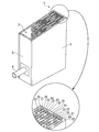
- FIG. 1 is a perspective view showing an overall configuration of a lithium ion battery according to an embodiment of the present invention.
- FIG. 2A is a partial cross-sectional view schematically showing the internal configuration of the lithium ion battery of FIG. 1, and
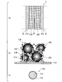
- FIG. 2B schematically shows the configuration of the positive electrode for the lithium ion battery in FIG. 2A.
- 2 (c) is a partially enlarged cross-sectional view shown in FIG.
- FIG. 1 is a perspective view showing an overall configuration of a lithium ion battery according to an embodiment of the present invention
- FIG. 2A is a partial cross-sectional view and a view schematically showing an internal configuration of the lithium ion battery of FIG. 2 (b) is a partially enlarged cross-sectional view schematically showing the configuration of the positive electrode for a lithium ion battery in FIG. 2 (a).
- the featured parts may be enlarged for convenience, and the shapes, dimensional ratios, etc. of each component are not limited to those shown. It shall be.
- the lithium ion battery 1 includes a laminate 2 including electrodes, an exterior body 4 that houses the laminate, and a lid 5 that seals the exterior body 4.
- the lithium ion battery 1 is, for example, a square lithium ion secondary battery.
- the exterior body 4 is composed of, for example, a metal housing.
- the laminate 2 has a positive electrode 21 for a lithium ion battery (hereinafter, also simply referred to as a positive electrode) and a negative electrode 22 for a lithium ion battery (hereinafter, also simply referred to as a negative electrode). ) And a separator 23 interposed between the positive electrode 21 and the negative electrode 22.
- the positive electrode 21, the negative electrode 22, and the separator are impregnated with the electrolytic solution.
- the positive electrode current collector 21A is connected to a positive electrode current collector (not shown), and the negative electrode current collector 22A is connected to a negative electrode current collector (not shown).
- the positive electrode 21 has a positive electrode current collector 21A and a positive electrode mixture layer 21B formed on the positive electrode current collector 21A and containing a positive electrode active material.
- the positive electrode current collector 21A is, for example, a plate-like body or a film-like body formed of a conductive material.
- a conductive material for example, a metal such as aluminum (Al) or nickel (Ni) can be used.
- the conductive material is aluminum (Al)
- an Al—Fe alloy such as JIS A8021 or pure aluminum such as JIS A1085 can be used.
- the thickness of the positive electrode current collector 21A is, for example, 8 ⁇ m or more and 15 ⁇ m or less.
- the positive electrode mixture layer 21B contains a lithium nickel composite oxide 21a and a metal phosphate 21b coated with the lithium nickel composite oxide 21a. Further, the positive electrode mixture layer 21B preferably contains a binder 21c and a conductive auxiliary agent 21d.
- the crystal structure near the surface of the positive electrode active material in the contact area between the positive electrode mixture layer and the electrolytic solution is altered regardless of the Ni concentration, which hinders the reaction of lithium insertion and desorption. Has been done. Therefore, by coating the surface of the positive electrode active material with a specific metal phosphate described later, which is a stable material, direct contact between the positive electrode active material and the electrolytic solution can be effectively prevented. Therefore, for example, the specific metal phosphate is used regardless of whether the lithium nickel composite oxide is a material of NCM811, NCM622, or NCM523, which is a lithium nickel-cobalt-manganese composite oxide (ternary active material). This makes it possible to prevent direct contact between the composite oxide and the electrolytic solution.
- lithium nickel composite oxide 21a a compound represented by, for example, 0.6 ⁇ x ⁇ 0.95, 0 ⁇ y0.2, 0 ⁇ z ⁇ 0.4 can be used in the above chemical formula.
- the lithium nickel composite oxide 21a has, for example, a particle shape.
- the lithium nickel composite oxide 21a may be primary particles or secondary particles in which the primary particles are agglomerated with each other.
- the metal phosphate 21b is one or more materials selected from the group consisting of VPO 4 , VP 2 O 7 and VPO 4 F, and is preferably VPO 4 F from the viewpoint of further improving durability. Further, the metal phosphate 21b does not necessarily have to cover the entire surface of the lithium nickel composite oxide 21a. For example, when the lithium nickel composite oxide 21a has a particle shape, the metal phosphate 21b preferably covers the surface of the particles of the lithium nickel composite oxide 21a. In the example of FIG. 2C, the metal phosphate 21b covers the entire surface of the lithium nickel composite oxide 21a, but the metal phosphate 21b must necessarily cover the entire surface of the lithium nickel composite oxide 21a. There is no. The metal phosphate 21b may cover at least a part of the surface of the lithium nickel composite oxide 21a.
- the mass ratio of the metal phosphate 21b to the lithium nickel composite oxide 21a is 0.01% by mass or more and 20% by mass or less.
- the nickel ratio in the lithium nickel composite oxide 21a is high, and the high energy density of the lithium ion battery is realized by the high nickel ratio.
- oxygen desorption from the surface of the lithium nickel composite oxide 21a occurs during the charge / discharge cycle. It can be sufficiently suppressed, and inactive nickel oxide (NiO) is less likely to be generated on the surface of the lithium nickel composite oxide 21a, which improves the durability of the lithium ion battery.
- the mass ratio of the metal phosphate 21b to the lithium nickel composite oxide 21a is less than 0.01% by mass, oxygen desorption from the surface of the lithium nickel composite oxide 21a cannot be suppressed, and the yarn teller effect ( Crystal strain is generated due to (stabilization of the energy state), inert nickel oxide is generated on the surface of the lithium nickel composite oxide 21a, and the crystal structure near the surface of the positive electrode active material is likely to change to a spinel structure.
- the mass ratio exceeds 20% by mass, the discharge capacity of lithium vanadium phosphate is smaller than the discharge capacity of the lithium nickel composite oxide, so that the discharge capacity of the entire positive electrode active material decreases, and the energy of the lithium ion battery is reduced. The density decreases. In addition, the resistance of the coating increases, and the output density of the lithium-ion battery decreases.
- the mass ratio of the metal phosphate 21b to the lithium nickel composite oxide 21a is preferably 0.1% by mass or more and 10% by mass or less. As a result, the durability of the lithium-ion battery can be further improved while achieving a high energy density.
- the lithium nickel composite oxide 21a is, in the above chemical formula LiNi x Co y M z O 2 , is preferably 0 ⁇ y ⁇ 0.2.
- the cobalt ions (Co 3+) unlike the nickel ions (Ni 3+), since no crystal strain due to Jahn-Teller effect, by increasing the cobalt ions (Co 3+), the surface of the lithium nickel composite oxide 21a not It is possible to suppress the formation of active nickel oxide. Therefore, by setting the ratio of cobalt (Co) in the lithium nickel composite oxide 21a to the above range, oxygen desorption can be further suppressed and the layered structure of the positive electrode active material can be further stabilized. In Chemical Formula LiNi x Co y M z O 2 , the discharge capacity of the lithium nickel composite oxide is reduced When it is 0.2 ⁇ y.
- binder 21c for example, polyvinylidene fluoride (PVDF) can be used.
- conductive auxiliary agent 21d for example, a carbon material can be used.
- the carbon material one or two or more selected from the group consisting of acetylene black, carbon nanotubes, graphene and graphite particles can be used.
- the carbon nanotube for example, VGCF synthesized by the vapor phase method (CVD) can be used.
- the negative electrode 22 has a negative electrode current collector 22A and a negative electrode mixture layer 22B formed on the negative electrode current collector 22A and containing a negative electrode active material.
- the negative electrode mixture layer 22B may contain a binder, a conductive auxiliary agent, a thickener and the like (not shown).
- the negative electrode current collector 22A is, for example, a plate-like body or a film-like body formed of a conductive material.
- a conductive material for example, a metal such as copper (Cu) or nickel (Ni) can be used.
- the conductive material is copper, for example, tough pitch copper such as JIS C1100 can be used.
- the thickness of the negative electrode current collector 22A is, for example, 5 ⁇ m or more and 10 ⁇ m or less.
- the negative electrode active material is not particularly limited, but is selected from the group consisting of, for example, natural graphite, artificial graphite, hard carbon, activated carbon, silicon (Si), silicon oxide (SiOx), tin (Sn) and tin oxide (SnOx). Can include one or more.
- binder of the negative electrode mixture layer 22B for example, one or two or more selected from the group consisting of polyvinylidene fluoride (PVDF), styrene butadiene rubber (SBR) and carboxymethyl cellulose (CMC) can be used.
- PVDF polyvinylidene fluoride
- SBR styrene butadiene rubber
- CMC carboxymethyl cellulose
- conductive auxiliary agent of the negative electrode mixture layer 22B for example, either or both of acetylene black and carbon nanotubes can be used.
- carbon nanotube for example, VGCF synthesized by the vapor phase method (CVD) can be used.
- the positive electrode current collector electrically connects a plurality of positive electrode current collectors 21A and the positive electrode terminal 6.
- the positive electrode current collector is made of, for example, aluminum (Al) or an aluminum alloy.
- the negative electrode current collector electrically connects a plurality of negative electrode current collectors 22A and negative electrode terminals (not shown).
- the negative electrode current collector is made of, for example, copper (Cu) or a copper alloy.
- the lithium ion battery 1 is a square type, but is not limited to this, and may be a laminated cell type or a cylindrical type. Further, the exterior body 4 of the lithium ion battery 1 is, for example, a metal housing, but the present invention is not limited to this, and the exterior body may be a laminated film.
- the laminated film can have a base material, a protective layer, and an adhesive layer.
- the base material is made of, for example, aluminum (Al) or stainless steel such as SUS.
- the protective layer is composed of one or more selected from the group consisting of, for example, polyethylene terephthalate (PET), polyether sulfone (PES) and nylon.
- the adhesive layer is made of, for example, a polyolefin resin.
- the polyolefin resin for example, either maleic anhydride-modified polyethylene or polypropylene (PP) can be used.
- the separator 23 is an insulating thin film, and is a porous body formed of a material such as polyethylene resin, polypropylene resin, or aramid resin. Further, the separator 23 may have a porous body and a coating layer formed on the surface of the porous body.
- a coating layer for example, a ceramic composed of silicon oxide (SiOx), aluminum oxide (Al 2 O 3 ), or an aramid resin can be used.
- the electrolytic solution can contain, for example, a solvent, a lithium salt, and an additive.
- the solvent is selected from the group consisting of, for example, ethylene carbonate (EC), propylene carbonate (PC), dimethyl carbonate (DMC), ethyl methyl carbonate (EMC), diethyl carbonate (DEC) and ⁇ -butyrotactone ( ⁇ BL). Alternatively, two or more can be used.
- EC ethylene carbonate
- PC propylene carbonate
- DMC dimethyl carbonate
- EMC ethyl methyl carbonate
- DEC diethyl carbonate
- ⁇ BL ⁇ -butyrotactone
- Lithium salts include, for example, LiPF 6 , lithium bis (fluorosulfonyl) imide (LiFSI), lithium bis (trifluoromethanesulfonyl) imide (LiTFSI), lithium bis (oxalate) borate (LiBOB), lithium difluorophosphate (LiDFP) and lithium.
- LiPF 6 lithium bis (fluorosulfonyl) imide
- LiTFSI lithium bis (trifluoromethanesulfonyl) imide
- LiBOB lithium bis (oxalate) borate
- LiDFP lithium difluorophosphate
- LiDFOB difluoro (oxalate) borate
- VC vinylene carbonate
- FEC fluoroethylene carbonate
- PS propane sultone
- PRS propene sultone
- Example 1-1 A predetermined amount of vanadium tetraacetate was dissolved in distilled water and stirred for 30 minutes to obtain Solution A. Further, NH 4 H 2 PO 4 having the same number of moles was dissolved in vanadium tetraacetate to obtain a solution B1. Solution B1 was added dropwise to Solution C in which nickel composite oxide (LiNi 0.8 Co 0.1 Mn 0.1 O 2 ) was dispersed in Solution A, and the mixture was stirred for 3 hours to obtain Solution D1. The solution D1 was dried in an oil bath at 60 ° C. and then heat-treated at 300 ° C. for 5 hours to obtain a positive electrode active material in which the surface of the lithium nickel composite oxide was coated with VPO 4 . Table 1 shows the mass ratio of the metal phosphate to the lithium nickel composite oxide in the obtained positive electrode active material.
- a positive electrode active material 94% by mass of the obtained positive electrode active material, 3% by mass of a carbon material as a conductive auxiliary agent, and 3% by mass of a PVDF binder as a binder were mixed to prepare a positive electrode mixture slurry to prepare a thickness. It was applied on a 15 ⁇ m aluminum foil. The coating amount of the positive electrode mixture slurry was 21.2 mg / cm 2 . Then, it was dried and rolled to obtain a positive electrode. The size of the positive electrode was 40 mm ⁇ 40 mm.
- a negative electrode mixture slurry 97% by mass of natural graphite, 1% by mass of carbon material as a conductive auxiliary agent, 1% by mass of SBR as a binder, and 1% by mass of CMC as a thickener are mixed to prepare a negative electrode mixture slurry. , It was applied on a rolled copper foil having a thickness of 8 ⁇ m. The coating amount of the negative electrode mixture slurry was 12.5 mg / cm 2 . Then, it was dried and rolled to obtain a negative electrode. The dimensions of the negative electrode were 44 mm ⁇ 44 mm.
- the positive electrode and the negative electrode obtained above and the porous separator made of polyolefin were prepared, the positive electrode, the porous separator and the negative electrode were laminated in this order, and these were wound to form a laminate.
- the laminated body was housed in the exterior body, and the positive electrode current collector and the negative electrode current collector were connected to the positive electrode terminal and the negative electrode terminal, respectively.
- 1.2M LiPF 6 is mixed with EC: 30 wt%, EMC: 40 wt%, DMC: 30 wt% to adjust the electrolytic solution, the outer body is filled with the electrolytic solution, and the outer body is sealed with a lid. I got a lithium-ion battery.
- Example 1-2 A positive electrode and a lithium ion battery were obtained in the same manner as in Example 1-1, except that the mass ratio of the metal phosphate to the lithium nickel composite oxide in the positive electrode active material was changed.
- Example 2-1 A predetermined amount of vanadium tetraacetate was dissolved in distilled water and stirred for 30 minutes to obtain Solution A. Further, NH 4 H 2 P 2 O 7 having the same number of moles was dissolved in vanadium tetraacetate to obtain a solution B2.
- Solution B2 was added dropwise to Solution C in which nickel composite oxide (LiNi 0.8 Co 0.1 Mn 0.1 O 2 ) was dispersed in Solution A, and the mixture was stirred for 3 hours to obtain Solution D2.
- the solution D2 was dried in an oil bath at 60 ° C. and then heat-treated at 300 ° C. for 5 hours to obtain a positive electrode active material in which the surface of a nickel composite oxide positive electrode was coated with VP 2 O 7 . Then, a positive electrode and a lithium ion battery were obtained in the same manner as in Example 1-1.
- Example 2-2 A positive electrode and a lithium ion battery were obtained in the same manner as in Example 2-1 except that the mass ratio of the metal phosphate to the lithium nickel composite oxide in the positive electrode active material was changed.
- Example 3-1 A predetermined amount of vanadium tetraacetate was dissolved in distilled water and stirred for 30 minutes to obtain Solution A. Further, NH 4 H 2 PO 4 having the same number of moles was dissolved in vanadium tetraacetate, and PTFE was further dispersed to obtain a solution B3. Solution B3 was added dropwise to Solution C in which nickel composite oxide (LiNi 0.8 Co 0.1 Mn 0.1 O 2 ) was dispersed in Solution A, and the mixture was stirred for 3 hours to obtain Solution D3. After drying the solution D3 at 60 ° C. in an oil bath, a heat treatment of 450 ° C. ⁇ 5 hours to obtain a cathode active material coated with a VPO 4 F on the surface of the nickel composite oxide. Then, a positive electrode and a lithium ion battery were obtained in the same manner as in Example 1-1.
- Example 3-2 A positive electrode and a lithium ion battery were obtained in the same manner as in Example 3-1 except that the mass ratio of the metal phosphate to the lithium nickel composite oxide in the positive electrode active material was changed.
- Example 1 A positive electrode and a lithium ion battery were obtained in the same manner as in Example 1-1, except that the surface of the lithium nickel composite oxide was not coated with a metal phosphate.
- the obtained lithium-ion battery was measured and evaluated by the following method.
- Capacity retention rate (600th cycle discharge capacity / 1st cycle discharge capacity) x 100 ... (2)
- Resistance increase rate (%) was calculated from the following equation (3), where the initial resistance was R 0 and the resistance after the time (t) required for 600 cycles had elapsed was R t .
- Resistance increase rate (%) R t / R 0 ⁇ 100 ⁇ ⁇ ⁇ (3) The measurement results are shown in Table 1.
- the mass ratio of VPO 4 was 0.5 mass%
- the initial resistance was 1.05 ⁇ , and it was found that high energy density was realized by the high nickel ratio.
- the capacity retention rate was higher than the capacity retention rate of Comparative Example 1 and the resistance increase rate was lower than the capacity retention rate of Comparative Example 1, and the durability was improved.
- Example 1-2 the mass ratio of VPO 4 to the lithium nickel composite oxide is 5.0% by mass, and the initial resistance is larger than the initial resistance of Example 1-1, but the capacity retention rate is Example 1. It was found that the resistance increase rate was higher than the capacity retention rate of -1, and the resistance increase rate was lower than the resistance increase rate of Example 1-1, so that the durability was further improved.
- the ratio was 0.5% by mass, the initial resistance was 1.06 ⁇ , and it was found that high energy density was realized by the high nickel ratio. Further, it was found that the capacity retention rate was higher than the capacity retention rate of Comparative Example 1 and the resistance increase rate was lower than the capacity retention rate of Comparative Example 1, and the durability was improved.
- Example 2-2 the mass ratio of VP 2 O 7 to the lithium nickel composite oxide was 5.0% by mass, and the initial resistance was larger than the initial resistance of Example 2-1. It was found that the capacity retention rate was higher than that of Example 2-1 and the resistance increase rate was lower than that of Example 2-1 and the durability was further improved.
- the initial resistance becomes 1.04 ⁇ , and it was found that high energy density can be realized by a high nickel ratio. Further, it was found that the capacity retention rate was higher than the capacity retention rate of Comparative Example 1 and the resistance increase rate was lower than the capacity retention rate of Comparative Example 1, and the durability was improved.
- Example 3-2 the mass ratio of VPO 4 F to the lithium nickel composite oxide was 5.0% by mass, and the initial resistance and the resistance increase rate were higher than the initial resistance and resistance increase rate of Example 3-1 respectively. However, it was found that the capacity retention rate was higher than the capacity retention rate of Example 1-1, and the durability was improved.
- the positive electrode for a lithium ion battery of the present invention can be applied to a lithium ion battery such as a primary battery or a secondary battery. Further, the lithium ion battery of the present invention can be applied to an electric vehicle (EV) such as a two-wheeled vehicle and a four-wheeled vehicle, and is particularly suitable for an electric vehicle and a hybrid vehicle.
- EV electric vehicle
- Lithium-ion battery 2 Laminated body 4 Exterior body 5 Lid body 6 Positive electrode terminal 21 Positive electrode 21A Positive electrode current collector 21B Positive electrode mixture layer 21a Lithium nickel composite oxide 21b Metal phosphate 21c Binder 21d Conductive aid 22 Negative electrode 22A Negative electrode collection Electrode 22B Negative electrode mixture layer 23 Separator
Landscapes
- Chemical & Material Sciences (AREA)
- Chemical Kinetics & Catalysis (AREA)
- Electrochemistry (AREA)
- General Chemical & Material Sciences (AREA)
- Engineering & Computer Science (AREA)
- Materials Engineering (AREA)
- Inorganic Chemistry (AREA)
- Composite Materials (AREA)
- Manufacturing & Machinery (AREA)
- Crystallography & Structural Chemistry (AREA)
- Battery Electrode And Active Subsutance (AREA)
Abstract
Description
上記金属リン酸塩は、化学式(a):MxPyOz(式中、Mは、バナジウム(V)、ニオブ(Nb)及びタンタル(Ta)のうちから選択された1以上の元素であり、1≦y/x≦1.33であり、4≦z/y≦5の範囲を有する)で表される。
また、上記リチウム複合酸化物は、以下の化学式(b)~(e)のいずれかで表される化合物である。
化学式(b):LiM2O4(式中、Mは、ニッケル(Ni)、マンガン(Mn)及びコバルト(Co)からなる群から選択された1以上である)
化学式(c):Li1+xM1-xO2(式中、Mは、ニッケル(Ni)、コバルト(Co)、マンガン(Mn)、チタン(Ti)、バナジウム(V)、鉄(Fe)、ニオブ(Nb)及びモリブデン(Mo)からなる群から選択された1以上であり、0<x≦0.3である)
化学式(d):LiaNibCocMndMeO2(式中、Mは、チタン(Ti)、バナジウム(V)、鉄(Fe)、ニオブ(Nb)及びモリブデン(Mo)からなる群から選択された1以上であり、1.1≦a<1.5、0<b<1、0≦c<1、0<d<1、0≦e<1及び0<b+c+d+e<1である)
化学式(e):Li1+x1M1-x1O2(式中、Mは、ニッケル(Ni)、コバルト(Co)、マンガン(Mn)、チタン(Ti)、バナジウム(V)、鉄(Fe)、ニオブ(Nb)及びモリブデン(Mo)からなる群から選択された1以上であり、0.1≦x1≦0.3である)
化学式(f):LibNi1-x-yCoxMyO2
(式中、Mは、マグネシウム(Mg)、アルミニウム(Al)、カルシウム(Ca)、チタン(Ti)、バナジウム(V)、クロム(Cr)、マンガン(Mn)、ニオブ(Nb)、ジルコニウム(Zr)およびモリブデン(Mo)から選ばれる少なくとも1種である。bは0.95≦b≦1.03、xは0<x≦0.15、yは0<y≦0.07、x+yはx+y≦0.16を満たす数値である。)
[1]正極集電体と、前記正極集電体に形成された正極合材層とを有し、
前記正極合材層が、リチウムニッケル複合酸化物と、前記リチウムニッケル複合酸化物を被覆した金属リン酸塩とを含み、
前記リチウムニッケル複合酸化物は、化学式LiNixCoyMzO2(式中のMは、Mn、Al、MgおよびWからなる群から選択される1以上の元素であり、x+y+z=1、0.6≦x<1.0)で表され、
前記金属リン酸塩は、VPO4、VP2O7およびVPO4Fからなる群から選択される1以上の材料であり、
前記リチウムニッケル複合酸化物に対する前記金属リン酸塩の質量比が、0.01質量%以上20質量%以下である、リチウムイオン電池用正極。
[2]前記化学式において、0<y≦0.2である、上記[1]に記載のリチウムイオン電池用正極。
[3]前記金属リン酸塩が、前記リチウムニッケル複合酸化物の表面の全体を被覆している、上記[1]に記載のリチウムイオン電池用正極。
[4]前記リチウムニッケル複合酸化物に対する前記金属リン酸塩の質量比が、0.1質量%以上10質量%以下である、上記[1]に記載のリチウムイオン電池用正極。
[5]前記リチウムニッケル複合酸化物は、化学式LiNixCoyMnzO2(x+y+z=1、0.6≦x<1.0)である、上記[1]~[4]のいずれかに記載のリチウムイオン電池用正極。
[6]前記金属リン酸塩はVP2O7である、上記[1]~[4]のいずれかに記載のリチウムイオン電池用正極。
[7]上記[1]~[6]のいずれかに記載のリチウムイオン電池用正極を備える、リチウムイオン電池。
図1は、本発明の実施形態に係るリチウムイオン電池の全体構成を示す斜視図であり、図2(a)は、図1のリチウムイオン電池の内部構成を概略的に示す部分断面図、図2(b)は、図2(b)は、図2(a)におけるリチウムイオン電池用正極の構成を概略的に示す部分拡大断面図である。なお、以下の説明で用いる図面は、特徴をわかりやすくするために、便宜上特徴となる部分を拡大して示している場合があり、各構成要素の形状、寸法比率等は図示するものに限らないものとする。
基材は、例えばアルミニウム(Al)、あるいはSUSなどのステンレスで構成される。保護層は、例えばポリエチレンテレフタレート(PET)、ポリエーテルスルホン(PES)およびナイロンからなる群から選択される1または2以上で構成される。接着層は、例えばポリオレフィン樹脂で構成される。ポリオレフィン樹脂としては、例えば、無水マレイン酸変性ポリエチレンおよびポリプロピレン(PP)のいずれかを用いることができる。
(実施例1-1)
所定量の四酢酸バナジウムを蒸留水に溶かし、30分間攪拌して溶液Aを得た。また、四酢酸バナジウムに、同じモル数のNH4H2PO4を溶かして溶液B1を得た。溶液Aにニッケル複合酸化物(LiNi0.8Co0.1Mn0.1O2)を分散させた溶液Cに、溶液B1を滴下して3時間攪拌し、溶液D1を得た。溶液D1を60℃のオイルバスにて乾燥後、300℃×5時間の熱処理を行い、リチウムニッケル複合酸化物の表面にVPO4を被覆した正極活物質を得た。得られた正極活物質における、リチウムニッケル複合酸化物に対する金属リン酸塩の質量比を、表1に示す。
正極活物質における、リチウムニッケル複合酸化物に対する金属リン酸塩の質量比を変えたこと以外は、実施例1-1と同様にして、正極およびリチウムイオン電池を得た。
所定量の四酢酸バナジウムを蒸留水に溶かし、30分間攪拌して溶液Aを得た。また、四酢酸バナジウムに、同じモル数のNH4H2P2O7を溶かして溶液B2を得た。溶液Aにニッケル複合酸化物(LiNi0.8Co0.1Mn0.1O2)を分散させた溶液Cに、溶液B2を滴下して3時間攪拌し、溶液D2を得た。溶液D2を60℃のオイルバスにて乾燥後、300℃×5時間の熱処理を行い、ニッケル複合酸化物正極の表面にVP2O7を被覆した正極活物質を得た。その後、実施例1-1と同様にして、正極およびリチウムイオン電池を得た。
正極活物質における、リチウムニッケル複合酸化物に対する金属リン酸塩の質量比を変えたこと以外は、実施例2-1と同様にして、正極およびリチウムイオン電池を得た。
所定量の四酢酸バナジウムを蒸留水に溶かし、30分間攪拌して溶液Aを得た。また、四酢酸バナジウムに、同じモル数のNH4H2PO4を溶かし、更にPTFEを分散させて溶液B3を得た。溶液Aにニッケル複合酸化物(LiNi0.8Co0.1Mn0.1O2)を分散させた溶液Cに、溶液B3を滴下して3時間攪拌し、溶液D3を得た。溶液D3を60℃のオイルバスにて乾燥後、450℃×5時間の熱処理を行い、ニッケル複合酸化物の表面にVPO4Fを被覆した正極活物質を得た。その後、実施例1-1と同様にして、正極およびリチウムイオン電池を得た。
正極活物質における、リチウムニッケル複合酸化物に対する金属リン酸塩の質量比を変えたこと以外は、実施例3-1と同様にして、正極およびリチウムイオン電池を得た。
リチウムニッケル複合酸化物の表面に金属リン酸塩を被覆しなかったこと以外は、実施例1-1と同様にして、正極およびリチウムイオン電池を得た。
初期抵抗は、環境温度25℃にて、SOC50%に調整し、3C放電を10秒間実施した。その際の電圧および電流の測定値を測定し、以下の式(1)から抵抗値を算出することにより求めた。
初期抵抗(R)=(OCV-10秒目電圧)/放電電流 ・・・(1)
環境温度45℃、充電条件0.6C、4.2Vカットオフ、放電条件1.2C、2.7Vカットオフとし、当該サイクルを600回実施した。容量維持率(%)は、以下の式(2)から求めた。
容量維持率(%)=(600サイクル目放電容量/1サイクル目放電容量)×100 ・・・(2)
抵抗増加率(%)は、初期抵抗をR0、600サイクルに掛かった時間(t)が経過した後の抵抗をRtとし、以下の式(3)から求めた。
抵抗増加率(%)=Rt/R0×100 ・・・(3)
測定結果を表1に示す。

2 積層体
4 外装体
5 蓋体
6 正極端子
21 正極
21A 正極集電体
21B 正極合材層
21a リチウムニッケル複合酸化物
21b 金属リン酸塩
21c バインダー
21d 導電助剤
22 負極
22A 負極集電体
22B 負極合材層
23 セパレータ
Claims (7)
- 正極集電体と、前記正極集電体に形成された正極合材層とを有し、
前記正極合材層が、リチウムニッケル複合酸化物と、前記リチウムニッケル複合酸化物を被覆した金属リン酸塩とを含み、
前記リチウムニッケル複合酸化物は、化学式LiNixCoyMzO2(式中のMは、Mn、Al、MgおよびWからなる群から選択される1以上の元素であり、x+y+z=1、0.6≦x<1.0)で表され、
前記金属リン酸塩は、VPO4、VP2O7およびVPO4Fからなる群から選択される1以上の材料であり、
前記リチウムニッケル複合酸化物に対する前記金属リン酸塩の質量比が、0.01質量%以上20質量%以下である、リチウムイオン電池用正極。 - 前記化学式において、0<y≦0.2である、請求項1に記載のリチウムイオン電池用正極。
- 前記金属リン酸塩が、前記リチウムニッケル複合酸化物の表面の全体を被覆している、請求項1に記載のリチウムイオン電池用正極。
- 前記リチウムニッケル複合酸化物に対する前記金属リン酸塩の質量比が、0.1質量%以上10質量%以下である、請求項1に記載のリチウムイオン電池用正極。
- 前記リチウムニッケル複合酸化物は、化学式LiNixCoyMnzO2(x+y+z=1、0.6≦x<1.0)である、請求項1~4のいずれか1項に記載のリチウムイオン電池用正極。
- 前記金属リン酸塩はVP2O7である、請求項1~4のいずれか1項に記載のリチウムイオン電池用正極。
- 請求項1~6のいずれか1項に記載のリチウムイオン電池用正極を備える、リチウムイオン電池。
Priority Applications (5)
| Application Number | Priority Date | Filing Date | Title |
|---|---|---|---|
| CN201980093407.4A CN113519078B (zh) | 2019-03-12 | 2019-03-12 | 锂离子电池用正极及锂离子电池 |
| DE112019007013.4T DE112019007013T5 (de) | 2019-03-12 | 2019-03-12 | Positive Elektrode für Lithium-Ionen-Batterie sowie Lithium-Ionen-Batterie |
| PCT/JP2019/010028 WO2020183612A1 (ja) | 2019-03-12 | 2019-03-12 | リチウムイオン電池用正極およびリチウムイオン電池 |
| JP2021504678A JP7179956B2 (ja) | 2019-03-12 | 2019-03-12 | リチウムイオン電池用正極およびリチウムイオン電池 |
| US17/437,433 US20220140349A1 (en) | 2019-03-12 | 2019-03-12 | Positive electrode for lithium ion battery and lithium ion battery |
Applications Claiming Priority (1)
| Application Number | Priority Date | Filing Date | Title |
|---|---|---|---|
| PCT/JP2019/010028 WO2020183612A1 (ja) | 2019-03-12 | 2019-03-12 | リチウムイオン電池用正極およびリチウムイオン電池 |
Publications (1)
| Publication Number | Publication Date |
|---|---|
| WO2020183612A1 true WO2020183612A1 (ja) | 2020-09-17 |
Family
ID=72427395
Family Applications (1)
| Application Number | Title | Priority Date | Filing Date |
|---|---|---|---|
| PCT/JP2019/010028 Ceased WO2020183612A1 (ja) | 2019-03-12 | 2019-03-12 | リチウムイオン電池用正極およびリチウムイオン電池 |
Country Status (5)
| Country | Link |
|---|---|
| US (1) | US20220140349A1 (ja) |
| JP (1) | JP7179956B2 (ja) |
| CN (1) | CN113519078B (ja) |
| DE (1) | DE112019007013T5 (ja) |
| WO (1) | WO2020183612A1 (ja) |
Families Citing this family (1)
| Publication number | Priority date | Publication date | Assignee | Title |
|---|---|---|---|---|
| WO2023173413A1 (zh) * | 2022-03-18 | 2023-09-21 | 宁德时代新能源科技股份有限公司 | 二次电池以及包含其的电池模块、电池包及用电装置 |
Citations (3)
| Publication number | Priority date | Publication date | Assignee | Title |
|---|---|---|---|---|
| JP2010027482A (ja) * | 2008-07-23 | 2010-02-04 | Sony Corp | 正極活物質の製造方法および正極活物質 |
| JP2016127024A (ja) * | 2014-12-26 | 2016-07-11 | 三星電子株式会社Samsung Electronics Co., Ltd. | 複合正極活物質、その製造方法、それを含む正極、及びそれを含むリチウム電池 |
| JP2017188424A (ja) * | 2016-03-30 | 2017-10-12 | Tdk株式会社 | リチウムイオン二次電池用正極活物質、及びそれを用いたリチウムイオン二次電池用正極並びにリチウムイオン二次電池 |
Family Cites Families (4)
| Publication number | Priority date | Publication date | Assignee | Title |
|---|---|---|---|---|
| WO2011027503A1 (ja) * | 2009-09-01 | 2011-03-10 | 日立ビークルエナジー株式会社 | 非水電解質二次電池 |
| JP5815354B2 (ja) | 2011-09-30 | 2015-11-17 | 富士重工業株式会社 | 蓄電デバイス及び蓄電デバイス用正極 |
| JP6753050B2 (ja) | 2015-10-26 | 2020-09-09 | 住友金属鉱山株式会社 | 非水系電解質二次電池用正極活物質、および該正極活物質を用いた非水系電解質二次電池 |
| US10211456B2 (en) * | 2016-03-30 | 2019-02-19 | Tdk Corporation | Positive electrode active material for lithium ion secondary battery, and lithium ion secondary battery positive electrode and lithium ion secondary battery using the same |
-
2019
- 2019-03-12 DE DE112019007013.4T patent/DE112019007013T5/de not_active Withdrawn
- 2019-03-12 WO PCT/JP2019/010028 patent/WO2020183612A1/ja not_active Ceased
- 2019-03-12 US US17/437,433 patent/US20220140349A1/en not_active Abandoned
- 2019-03-12 CN CN201980093407.4A patent/CN113519078B/zh active Active
- 2019-03-12 JP JP2021504678A patent/JP7179956B2/ja active Active
Patent Citations (3)
| Publication number | Priority date | Publication date | Assignee | Title |
|---|---|---|---|---|
| JP2010027482A (ja) * | 2008-07-23 | 2010-02-04 | Sony Corp | 正極活物質の製造方法および正極活物質 |
| JP2016127024A (ja) * | 2014-12-26 | 2016-07-11 | 三星電子株式会社Samsung Electronics Co., Ltd. | 複合正極活物質、その製造方法、それを含む正極、及びそれを含むリチウム電池 |
| JP2017188424A (ja) * | 2016-03-30 | 2017-10-12 | Tdk株式会社 | リチウムイオン二次電池用正極活物質、及びそれを用いたリチウムイオン二次電池用正極並びにリチウムイオン二次電池 |
Also Published As
| Publication number | Publication date |
|---|---|
| DE112019007013T5 (de) | 2021-12-02 |
| CN113519078B (zh) | 2025-07-22 |
| JP7179956B2 (ja) | 2022-11-29 |
| JPWO2020183612A1 (ja) | 2021-11-18 |
| CN113519078A (zh) | 2021-10-19 |
| US20220140349A1 (en) | 2022-05-05 |
Similar Documents
| Publication | Publication Date | Title |
|---|---|---|
| JP4245532B2 (ja) | 非水電解質二次電池 | |
| CN101150189B (zh) | 正极活性材料和使用其的锂电池 | |
| JP5972513B2 (ja) | カソード及びこれを採用したリチウム電池 | |
| JP5341837B2 (ja) | 正極、非水電解質電池及び電池パック | |
| JP5099168B2 (ja) | リチウムイオン二次電池 | |
| WO2006109495A1 (ja) | 非水電解液二次電池 | |
| JP6697377B2 (ja) | リチウムイオン二次電池 | |
| JP5141582B2 (ja) | 非水電解質二次電池 | |
| KR20070064400A (ko) | 리튬이온 2차전지 | |
| WO2013042419A1 (ja) | 非水二次電池 | |
| KR20150031688A (ko) | 복합양극활물질, 그 제조방법 및 이를 채용한 양극과 리튬이차전지 | |
| JPWO2016021684A1 (ja) | 正極及びそれを用いた二次電池 | |
| JP2022114665A (ja) | 正極活物質層形成用材料および該正極活物質層形成用材料を用いた非水電解質二次電池 | |
| CN112673503A (zh) | 非水电解质蓄电元件和蓄电装置 | |
| KR100834053B1 (ko) | 양극, 이를 포함하는 리튬 이차 전지, 및 이를 포함하는 하이브리드 커패시터 | |
| JP4770426B2 (ja) | 捲回型蓄電装置 | |
| JP7179956B2 (ja) | リチウムイオン電池用正極およびリチウムイオン電池 | |
| JP5646661B2 (ja) | 正極、非水電解質電池及び電池パック | |
| EP2613384B1 (en) | Cathode active material for secondary battery | |
| US20230216060A1 (en) | Positive electrode for lithium-ion battery, lithium-ion battery and method for producing positive electrode for lithium-ion battery | |
| KR20080029480A (ko) | 리튬 이차 전지, 및 하이브리드 커패시터 | |
| US11664490B2 (en) | Positive electrode for lithium ion battery, lithium ion battery and method of producing positive electrode for lithium ion battery | |
| JP6981455B2 (ja) | リチウムイオン二次電池用負極活物質の製造方法 | |
| JP2024092833A (ja) | 電圧変動抑制素子及び再生可能エネルギー蓄電システム | |
| KR20240054512A (ko) | 탄닌산 코팅층을 포함하는 양극 활물질 및 이의 제조 방법 |
Legal Events
| Date | Code | Title | Description |
|---|---|---|---|
| 121 | Ep: the epo has been informed by wipo that ep was designated in this application |
Ref document number: 19918609 Country of ref document: EP Kind code of ref document: A1 |
|
| ENP | Entry into the national phase |
Ref document number: 2021504678 Country of ref document: JP Kind code of ref document: A |
|
| 122 | Ep: pct application non-entry in european phase |
Ref document number: 19918609 Country of ref document: EP Kind code of ref document: A1 |
|
| WWG | Wipo information: grant in national office |
Ref document number: 201980093407.4 Country of ref document: CN |