WO2020183515A1 - 情報処理装置 - Google Patents
情報処理装置 Download PDFInfo
- Publication number
- WO2020183515A1 WO2020183515A1 PCT/JP2019/009265 JP2019009265W WO2020183515A1 WO 2020183515 A1 WO2020183515 A1 WO 2020183515A1 JP 2019009265 W JP2019009265 W JP 2019009265W WO 2020183515 A1 WO2020183515 A1 WO 2020183515A1
- Authority
- WO
- WIPO (PCT)
- Prior art keywords
- lead
- component
- information
- base material
- leads
- Prior art date
- Legal status (The legal status is an assumption and is not a legal conclusion. Google has not performed a legal analysis and makes no representation as to the accuracy of the status listed.)
- Ceased
Links
Images




Classifications
-
- G—PHYSICS
- G01—MEASURING; TESTING
- G01N—INVESTIGATING OR ANALYSING MATERIALS BY DETERMINING THEIR CHEMICAL OR PHYSICAL PROPERTIES
- G01N21/00—Investigating or analysing materials by the use of optical means, i.e. using sub-millimetre waves, infrared, visible or ultraviolet light
- G01N21/84—Systems specially adapted for particular applications
Definitions
- the present invention relates to an information processing device that calculates information about lead components.
- the lead component is mounted on the substrate by inserting the lead into the insertion hole formed in the substrate, as described in the following patent document.
- the present specification discloses an information processing apparatus that calculates information about the lead component based on image data of a substrate on which an insertion hole for inserting a lead of the lead component is formed. ..
- information on lead components can be appropriately calculated based on the image data of the substrate.
- FIG. 1 shows the component mounting machine 10.
- the component mounting machine 10 is a device for executing component mounting work on the circuit base material 12.
- the component mounting machine 10 includes an apparatus main body 20, a base material transfer holding device 22, a component mounting device 24, a mark camera 26, a parts camera 28, a component supply device 30, a loose component supply device 32, and a control device (see FIG. 3) 36.
- Examples of the circuit board 12 include a circuit board, a base material having a three-dimensional structure, and the like, and examples of the circuit board include a printed wiring board and a printed circuit board.
- the device main body 20 is composed of a frame 40 and a beam 42 mounted on the frame 40.
- the base material transfer holding device 22 is arranged at the center of the frame 40 in the front-rear direction, and has a transfer device 50 and a clamp device 52.
- the transport device 50 is a device that transports the circuit base material 12
- the clamp device 52 is a device that holds the circuit base material 12.
- the base material transport / holding device 22 transports the circuit base material 12 and holds the circuit base material 12 fixedly at a predetermined position.
- the transport direction of the circuit base material 12 is referred to as the X direction
- the horizontal direction perpendicular to that direction is referred to as the Y direction
- the vertical direction is referred to as the Z direction. That is, the width direction of the component mounting machine 10 is the X direction, and the front-rear direction is the Y direction.
- the component mounting device 24 is arranged on the beam 42, and has two work heads 60 and 62 and a work head moving device 64. As shown in FIG. 2, a suction nozzle 66 is provided on the lower end surfaces of the work heads 60 and 62, and the suction nozzle 66 sucks and holds the component. Further, the work head moving device 64 has an X direction moving device 68, a Y direction moving device 70, and a Z direction moving device 72. Then, the two work heads 60 and 62 are integrally moved to an arbitrary position on the frame 40 by the X-direction moving device 68 and the Y-direction moving device 70.
- the work heads 60 and 62 are detachably attached to the sliders 74 and 76, and the Z-direction moving device 72 individually moves the sliders 74 and 76 in the vertical direction. That is, the work heads 60 and 62 are individually moved in the vertical direction by the Z-direction moving device 72.
- the mark camera 26 is attached to the slider 74 in a state of facing downward, and is moved in the X direction, the Y direction, and the Z direction together with the work head 60. As a result, the mark camera 26 images an arbitrary position on the frame 40. As shown in FIG. 1, the parts camera 28 is arranged between the base material transporting and holding device 22 on the frame 40 and the parts supply device 30 in a state of facing upward. As a result, the parts camera 28 images the parts held by the suction nozzles 66 of the work heads 60 and 62.
- the parts supply device 30 is arranged at one end of the frame 40 in the front-rear direction.
- the parts supply device 30 includes a tray-type parts supply device 78 and a feeder-type parts supply device (see FIG. 3) 80.
- the tray-type component supply device 78 is a device that supplies components in a state of being placed on the tray.
- the feeder type component supply device 80 is a device that supplies components by a tape feeder and a stick feeder (not shown).
- the loose parts supply device 32 is arranged at the other end of the frame 40 in the front-rear direction.
- the loose parts supply device 32 is a device that aligns a plurality of parts that are scattered apart and supplies the parts in the aligned state. That is, it is a device that aligns a plurality of parts in an arbitrary posture in a predetermined posture and supplies the parts in the predetermined posture.
- Examples of the parts supplied by the parts supply device 30 and the loose parts supply device 32 include electronic circuit parts, solar cell components, power module components, and the like.
- electronic circuit parts include parts having leads, parts having no leads, and the like.
- the control device 36 includes a controller 100, a plurality of drive circuits 102, and an image processing device 106.
- the plurality of drive circuits 102 are connected to the transfer device 50, the clamp device 52, the work heads 60 and 62, the work head moving device 64, the tray type parts supply device 78, the feeder type parts supply device 80, and the loose parts supply device 32.
- the controller 100 includes a CPU, ROM, RAM, etc., and is mainly a computer, and is connected to a plurality of drive circuits 102. As a result, the operation of the base material transfer holding device 22, the component mounting device 24, and the like is controlled by the controller 100. Further, the controller 100 is also connected to the image processing device 106.
- the image processing device 106 processes the image data obtained by the mark camera 26 and the parts camera 28, and the controller 100 acquires various information from the image data.
- components are mounted on the circuit substrate 12 held by the substrate transfer holding device 22 according to the above configuration.
- various components can be mounted on the circuit base material 12, but a case where the lead component (see FIG. 4) 110 is mounted on the circuit base material 12 will be described below.
- the circuit base material 12 is conveyed to a working position, and is fixedly held by the clamp device 52 at that position.
- the mark camera 26 moves above the circuit base material 12 and images the circuit base material 12.
- the component supply device 30 or the loose component supply device 32 supplies the lead component 110 at a predetermined supply position.
- one of the work heads 60 and 62 moves above the supply position of the component, and the suction nozzle 66 sucks and holds the component main body portion (see FIG. 4) 112 of the lead component 110.
- the work heads 60 and 62 holding the lead component 110 move above the parts camera 28, and the lead component 110 held by the suction nozzle 66 is imaged by the parts camera 28.
- the imaging data of the lead component 110 by the parts camera 28 is transmitted to the controller 100, and the imaging data is analyzed by the controller 100.
- the controller 100 recognizes the lead (see FIG. 4) 114 of the lead component 110 based on the imaging data, and calculates information about the lead 114 (hereinafter, referred to as “calculated lead information”).
- the calculated lead information includes information indicating the number of leads 114, the position of the leads 114, and the wire diameter of the leads 114.
- the information indicating the position of the lead 114 includes information indicating the tip position of the lead 114, the pitch between leads, the arrangement direction of the leads, and the like.
- the controller 100 uses the calculated lead information to check the lead component 110 held in the suction nozzle 66. Specifically, the controller 100 stores information regarding a reference lead (hereinafter, referred to as "reference lead information").
- the reference lead information includes information indicating the number of leads as a reference for the lead component to be mounted, the pitch between leads, the arrangement direction of leads, and the wire diameter of leads. Then, in the controller 100, the number of leads, the pitch between leads, the arrangement direction of leads, and the wire diameter of the leads of the calculated lead information are the number of leads of the reference lead information, the pitch between leads, the arrangement direction of leads, and the wire diameter of the leads. To determine if it matches.
- the suction nozzle 66 holds a component different from the component to be mounted, at least one of the number of leads, the pitch between leads, the lead arrangement direction, and the wire diameter of the leads in the calculation lead information is the reference lead. It differs from the number of information leads, the pitch between leads, the lead arrangement direction, and the lead wire diameter. In such a case, error notification, disposal of the held parts, and the like are performed, and the mounting work of the parts held by the suction nozzle 66 is not executed. Further, even if the suction nozzle 66 holds the component to be mounted, if the lead 114 is missing or the lead 114 is greatly bent, the number of leads in the calculation lead information, the pitch between leads, and the like.
- At least one of the lead arrangement directions is different from the number of leads, the lead-to-lead pitch, and the lead arrangement direction of the reference lead information. Even in such a case, error notification, disposal of the held parts, and the like are performed, and the mounting work of the parts held by the suction nozzle 66 is not executed. That is, the controller 100 compares the calculated lead information with the reference lead information, and determines whether or not the component held in the suction nozzle 66 is a component to be mounted and whether or not it is a defective product. doing. Then, when it is determined that the component held by the suction nozzle 66 is a component to be mounted and is not a defective product, the subsequent mounting work of the component is executed.
- the controller 100 attaches the work heads 60 and 62 holding the lead component 110 to the circuit base material 12. Move above. At this time, the controller 100 works so that the insertion hole (see FIG. 4) 120 formed in the circuit base material 12 and the tip of the lead 114 of the lead component 110 held by the suction nozzle 66 overlap in the vertical direction. The operation of the head moving device 64 is controlled.
- the controller 100 corrects the position of the insertion hole 120 stored in the controller 100 based on the error of the holding position of the circuit base material 12 calculated based on the imaging data of the mark camera 26. Subsequently, the controller 100 uses the information indicating the position of the corrected insertion hole 120 and the information indicating the tip position of the lead 114 included in the calculated lead information to move the insertion hole 120 and the tip of the lead 114 in the vertical direction.
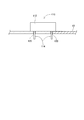
- the operation of the work head moving device 64 is controlled so as to overlap each other, that is, to match the XY coordinates. Then, the controller 100 lowers the work heads 60 and 62, so that the lead 114 of the lead component 110 is inserted into the insertion hole 120 formed in the circuit base material 12, as shown in FIG.
- the work of mounting the lead component 110 on the circuit base material 12 is executed by using the imaging data of the mark camera 26 and the parts camera 28. Further, before the lead component 110 is mounted on the circuit base material 12, the operation of confirming the component held in the suction nozzle 66 is executed by using the calculated lead information and the reference lead information, which is appropriate. Parts, that is, parts to be mounted that are not damaged or bent, can be mounted on the circuit base material 12.
- the pitch-to-pitch distance in the reference lead information is different from the pitch-to-pitch distance of the normal component. With such inaccurate reference lead information, it is not possible to properly confirm the parts held by the suction nozzle 66 during the mounting work.
- the circuit base material 12 is imaged by the mark camera 26 before the mounting work is executed, and reference read information is created based on the imaged data.
- the circuit base material 12 to which the component is mounted is transported to the working position by the transport device 50, and is fixedly held by the clamp device 52 at that position.
- the mark camera 26 moves above the circuit base material 12 and images the circuit base material 12.
- the planned mounting position of any component is imaged, and for example, the imaged data of the image 150 shown in FIG. 5 is created.
- the image 150 is an information image showing the planned mounting position of the lead component A, and the coordinates A (X0, Y0) are stored in advance in the controller 100 as information indicating the planned mounting position of the lead component A. Then, the controller 100 analyzes the imaging data and recognizes the positions of the plurality of insertion holes 152 formed in the circuit base material 12. As a result, the controller 100 calculates the coordinates of each of the plurality of insertion holes 152 with reference to the coordinates A (X0, Y0). That is, for example, the coordinates of the insertion hole 152a (X1, Y1), the coordinates of the insertion hole 152b (X2, Y2), the coordinates of the insertion hole 152c (X3, Y3), and so on are calculated.
- the inter-pitch distance of the insertion holes 152 is calculated based on the coordinates of the plurality of insertion holes 152.
- the arrangement direction of the insertion holes 152 and the number of insertion holes 152 are calculated. Since the plurality of insertion holes 152 are holes for inserting the leads of the lead component A, the inter-pitch distance, the arrangement direction, and the number of the insertion holes 152 are the inter-pitch distance, the arrangement direction, and the number of the leads of the lead component A. It is the same as the number.
- the calculated inter-pitch distance of the insertion holes 152, the arrangement direction of the insertion holes 152, and the number of insertion holes 152 are used as the inter-pitch distance, arrangement direction, and number of the leads of the lead component A, that is, as reference lead information. It is stored in the controller 100.
- the controller 100 also calculates the inner diameter of each of the plurality of insertion holes 152 based on the imaging data. Since the insertion hole 152 is a hole for inserting the lead of the lead component A, the inner diameter of the insertion hole 152 is slightly larger than the wire diameter of the lead of the lead component A, that is, the lead diameter. Therefore, a numerical value obtained by multiplying the calculated inner diameter of the insertion hole 152 by a reduction ratio in consideration of clearance, for example, 0.7, is stored in the controller 100 as the lead diameter of the lead component A, that is, as reference lead information. To.
- the circuit base material 12 is imaged by the mark camera 26, and the reference read information is created based on the imaged data, so that the burden on the operator can be reduced. Further, although the leads of the lead component may bend, the insertion holes formed in the circuit base material 12 are usually formed at accurate positions. Therefore, the accuracy of the reference read information can be ensured by creating the reference read information based on the imaging data of the circuit base material 12.
- the planned mounting positions of the plurality of lead components on the circuit base material 12 are densely packed, it may not be known which of the plurality of insertion holes corresponds to one lead component.
- the planned mounting positions 160a to g of the seven lead parts B1 to 7 are densely packed.
- the insertion hole 162a at the planned mounting position 160a and the insertion hole 162b at the planned mounting position 160b are insertion holes corresponding to one lead component, for example, an insertion hole into which the lead of the lead component B1 is inserted.
- the reference lead information is calculated, the reference lead information different from the actual lead component B1 is created.
- the insertion hole 162a at the planned mounting position 160a and the insertion hole 162b at the planned mounting position 160b are the insertion holes corresponding to the lead component B1, and the actual number of leads of the lead component B1. Is 2, but the number of reads in the calculated reference read information is 4.
- any insertion hole among the plurality of insertion holes can be set as corresponding to one lead component by user operation. That is, for example, the two insertion holes 162a correspond to the lead component B1 and the two insertion holes 162b correspond to the lead component B2, and can be set by user operation. As a result, it is possible to appropriately create reference lead information for each lead component even when a plurality of lead component mounting positions are densely packed.
- the circuit base material 12 may have holes formed for other purposes than the insertion holes for inserting the leads of the lead parts.
- three insertion holes 172 are formed at the planned mounting position 170 of the lead component C, and the purpose is to insert the lead next to the three insertion holes 172.
- No hole 174 is formed.
- the insertion hole 172 and the hole 174 for which the lead is not inserted are the insertion holes into which the leads of the lead component C are inserted, and the actual lead component C is calculated. Criteria lead information different from is created.
- the actual number of leads of the lead component C is 3.
- the number of reads in the calculated reference read information is 7.
- any hole can be deleted by user operation. That is, for example, the four holes 174 formed next to the three insertion holes 172 are deleted by a user operation. This makes it possible to calculate the reference lead information of the lead component C except for the hole 174, which is not intended for lead insertion.
- Reference lead information may be calculated for all the planned mounting positions of the circuit base material 12 based on the imaging data of the circuit base material 12, and the reference lead information may be calculated for a part of the planned mounting positions of the circuit base material 12.
- the reference read information may be calculated based on the imaging data of the circuit base material 12. For example, when the reference lead information is calculated based on the imaging data for a part of the circuit base material 12 to be mounted, the reference lead information is calculated for the planned mounting position of the lead component having a large number of leads. It is preferable to be done. Then, the operator may manually input the reference lead information of the lead component having a small number of leads. As a result, the burden on the operator can be reduced.
- the component mounting machine 10 is an example of a working machine.
- the circuit base material 12 is an example of a substrate.
- the mark camera 26 is an example of an imaging device.
- the control device 36 is an example of an information processing device.
- the lead component 110 is an example of a lead component.
- the lead 114 is an example of a lead.
- the insertion holes 120, 152, 162 are examples of insertion holes.
- the reference read information is calculated based on the imaging data of the circuit base material 12, but it is based on the drawing data, CAD data, etc. for drawing the circuit base material 12.
- the reference read information may be calculated. That is, the reference read information may be calculated based on the image data that is the basis of the image of the circuit base material 12, and the imaging data, drawing data, CAD data, and the like are included in the image data.
- the reference lead information is calculated before the mounting work is executed, but it is different from the component mounting machine 10 in which the mounting work is executed.
- Reference read information may be calculated in the working machine.
- the reference read information may be calculated not only by the working machine but also by an inspection machine having an imaging device or the like.
- the image pickup data of the circuit base material 12 may be acquired from the image pickup device and the reference read information may be calculated.
Landscapes
- Physics & Mathematics (AREA)
- Health & Medical Sciences (AREA)
- Life Sciences & Earth Sciences (AREA)
- Chemical & Material Sciences (AREA)
- Analytical Chemistry (AREA)
- Biochemistry (AREA)
- General Health & Medical Sciences (AREA)
- General Physics & Mathematics (AREA)
- Immunology (AREA)
- Pathology (AREA)
- Investigating Materials By The Use Of Optical Means Adapted For Particular Applications (AREA)
- Supply And Installment Of Electrical Components (AREA)
Abstract
リード部品のリードを挿入するための挿入穴が形成された基板の画像データに基づいて、リード部品に関する情報を演算する情報処理装置。
Description
本発明は、リード部品に関する情報を演算する情報処理装置に関するものである。
リード部品は、下記特許文献に記載されているように、基板に形成された挿入穴にリードが挿入されることで、基板に装着される。
リード部品のリードを、基板に形成された挿入穴に適切に挿入するために、リード部品に関する情報を適切に演算することが望まれている。
上記課題を解決するために、本明細書は、リード部品のリードを挿入するための挿入穴が形成された基板の画像データに基づいて、前記リード部品に関する情報を演算する情報処理装置を開示する。
本開示によれば、基板の画像データに基づいて、リード部品に関する情報を適切に演算することができる。
以下、本発明を実施するための形態として、本発明の実施例を、図を参照しつつ詳しく説明する。
図1に、部品実装機10を示す。部品実装機10は、回路基材12に対する部品の実装作業を実行するための装置である。部品実装機10は、装置本体20、基材搬送保持装置22、部品装着装置24、マークカメラ26、パーツカメラ28、部品供給装置30、ばら部品供給装置32、制御装置(図3参照)36を備えている。なお、回路基材12として、回路基板、三次元構造の基材等が挙げられ、回路基板として、プリント配線板、プリント回路板等が挙げられる。
装置本体20は、フレーム40と、そのフレーム40に上架されたビーム42とによって構成されている。基材搬送保持装置22は、フレーム40の前後方向の中央に配設されており、搬送装置50とクランプ装置52とを有している。搬送装置50は、回路基材12を搬送する装置であり、クランプ装置52は、回路基材12を保持する装置である。これにより、基材搬送保持装置22は、回路基材12を搬送するとともに、所定の位置において、回路基材12を固定的に保持する。なお、以下の説明において、回路基材12の搬送方向をX方向と称し、その方向に直角な水平の方向をY方向と称し、鉛直方向をZ方向と称する。つまり、部品実装機10の幅方向は、X方向であり、前後方向は、Y方向である。
部品装着装置24は、ビーム42に配設されており、2台の作業ヘッド60,62と作業ヘッド移動装置64とを有している。各作業ヘッド60,62の下端面には、図2に示すように、吸着ノズル66が設けられており、その吸着ノズル66によって部品を吸着保持する。また、作業ヘッド移動装置64は、X方向移動装置68とY方向移動装置70とZ方向移動装置72とを有している。そして、X方向移動装置68とY方向移動装置70とによって、2台の作業ヘッド60,62は、一体的にフレーム40上の任意の位置に移動させられる。また、各作業ヘッド60,62は、スライダ74,76に着脱可能に装着されており、Z方向移動装置72は、スライダ74,76を個別に上下方向に移動させる。つまり、作業ヘッド60,62は、Z方向移動装置72によって、個別に上下方向に移動させられる。
マークカメラ26は、下方を向いた状態でスライダ74に取り付けられており、作業ヘッド60とともに、X方向,Y方向およびZ方向に移動させられる。これにより、マークカメラ26は、フレーム40上の任意の位置を撮像する。パーツカメラ28は、図1に示すように、フレーム40上の基材搬送保持装置22と部品供給装置30との間に、上を向いた状態で配設されている。これにより、パーツカメラ28は、作業ヘッド60,62の吸着ノズル66に保持された部品を撮像する。
部品供給装置30は、フレーム40の前後方向での一方側の端部に配設されている。部品供給装置30は、トレイ型部品供給装置78とフィーダ型部品供給装置(図3参照)80とを有している。トレイ型部品供給装置78は、トレイ上に載置された状態の部品を供給する装置である。フィーダ型部品供給装置80は、テープフィーダ、スティックフィーダ(図示省略)によって部品を供給する装置である。
ばら部品供給装置32は、フレーム40の前後方向での他方側の端部に配設されている。ばら部品供給装置32は、ばらばらに散在された状態の複数の部品を整列させて、整列させた状態で部品を供給する装置である。つまり、任意の姿勢の複数の部品を、所定の姿勢に整列させて、所定の姿勢の部品を供給する装置である。なお、部品供給装置30および、ばら部品供給装置32によって供給される部品として、電子回路部品,太陽電池の構成部品,パワーモジュールの構成部品等が挙げられる。また、電子回路部品には、リードを有する部品,リードを有さない部品等が有る。
制御装置36は、図3に示すように、コントローラ100、複数の駆動回路102、画像処理装置106を備えている。複数の駆動回路102は、上記搬送装置50、クランプ装置52、作業ヘッド60,62、作業ヘッド移動装置64、トレイ型部品供給装置78、フィーダ型部品供給装置80、ばら部品供給装置32に接続されている。コントローラ100は、CPU,ROM,RAM等を備え、コンピュータを主体とするものであり、複数の駆動回路102に接続されている。これにより、基材搬送保持装置22、部品装着装置24等の作動が、コントローラ100によって制御される。さらに、コントローラ100は、画像処理装置106にも接続されている。画像処理装置106は、マークカメラ26およびパーツカメラ28によって得られた画像データを処理するものであり、コントローラ100は、画像データから各種情報を取得する。
部品実装機10では、上述した構成によって、基材搬送保持装置22に保持された回路基材12に対して部品の装着作業が行われる。部品実装機10では、種々の部品を回路基材12に装着することが可能であるが、リード部品(図4参照)110を回路基材12に装着する場合について、以下に説明する。
具体的には、回路基材12が、作業位置まで搬送され、その位置において、クランプ装置52によって固定的に保持される。次に、マークカメラ26が、回路基材12の上方に移動し、回路基材12を撮像する。これにより、回路基材12の保持位置等に関する情報が得られる。また、部品供給装置30若しくは、ばら部品供給装置32が、所定の供給位置において、リード部品110を供給する。そして、作業ヘッド60,62の何れかが、部品の供給位置の上方に移動し、吸着ノズル66によって、リード部品110の部品本体部(図4参照)112を吸着保持する。
続いて、リード部品110を保持した作業ヘッド60,62が、パーツカメラ28の上方に移動し、パーツカメラ28によって、吸着ノズル66に保持されたリード部品110が撮像される。これにより、部品の保持位置等に関する情報が得られる。詳しくは、パーツカメラ28によるリード部品110の撮像データがコントローラ100に送信され、コントローラ100において、撮像データが分析される。この際、コントローラ100は、撮像データに基づいて、リード部品110のリード(図4参照)114を認識し、リード114に関する情報(以下、「演算リード情報」と記載する)を演算する。演算リード情報には、リード114の本数,リード114の位置,リード114の線径を示す情報が含まれる。また、リード114の位置を示す情報には、リード114の先端位置,リード間ピッチ,リードの配列方向などを示す情報が含まれる。
そして、コントローラ100は、演算リード情報を演算すると、演算リード情報を利用して、吸着ノズル66に保持されているリード部品110の確認作業を行う。詳しくは、コントローラ100には、基準となるリードに関する情報(以下、「基準リード情報」と記載する)が記憶されている。基準リード情報は、装着対象のリード部品の基準となるリードの本数,リード間ピッチ,リードの配列方向,リードの線径を示す情報が含まれている。そして、コントローラ100は、演算リード情報のリードの本数,リード間ピッチ,リードの配列方向,リードの線径が、基準リード情報のリードの本数,リード間ピッチ,リードの配列方向,リードの線径と一致するか否かを判断する。
この際、吸着ノズル66が装着対象の部品と異なる部品を保持している場合は、演算リード情報のリードの本数,リード間ピッチ,リードの配列方向,リードの線径の少なくとも1つが、基準リード情報のリードの本数,リード間ピッチ,リードの配列方向,リードの線径と異なる。このような場合には、エラー報知,保持している部品の廃棄などが行われ、吸着ノズル66に保持されている部品の装着作業は実行されない。また、吸着ノズル66が装着対象の部品を保持していても、リード114が欠損している場合,リード114が大きく曲がっている場合などには、演算リード情報のリードの本数,リード間ピッチ,リードの配列方向の少なくとも1つが、基準リード情報のリードの本数,リード間ピッチ,リードの配列方向と異なる。このような場合にも、エラー報知,保持している部品の廃棄などが行われ、吸着ノズル66に保持されている部品の装着作業は実行されない。つまり、コントローラ100は、演算リード情報と基準リード情報とを比較して、吸着ノズル66に保持されている部品が、装着対象の部品であるか否か、及び、不良品でないか否かを判断している。そして、吸着ノズル66に保持されている部品が、装着対象の部品であり、かつ、不良品でないと判断された場合に、以降の部品の装着作業が実行される。
吸着ノズル66に保持されている部品が、装着対象の部品であり、かつ、不良品でないと判断されると、コントローラ100は、リード部品110を保持する作業ヘッド60,62を、回路基材12の上方に移動させる。この際、コントローラ100は、回路基材12に形成された挿入穴(図4参照)120と、吸着ノズル66に保持されたリード部品110のリード114の先端とが上下方向において重なるように、作業ヘッド移動装置64の作動が制御される。
詳しくは、回路基材12に形成された挿入穴120の位置に関する情報は、予めコントローラ100に記憶されている。そして、コントローラ100は、マークカメラ26の撮像データに基づいて演算された回路基材12の保持位置の誤差に基づいて、コントローラ100に記憶されている挿入穴120の位置を補正する。続いて、コントローラ100は、補正した挿入穴120の位置を示す情報と、演算リード情報に含まれるリード114の先端位置を示す情報を利用して、挿入穴120とリード114の先端とが上下方向において重なるように、つまり、XY座標が一致するように、作業ヘッド移動装置64の作動が制御される。そして、コントローラ100が、作業ヘッド60,62を下降させることで、図4に示すように、リード部品110のリード114が、回路基材12に形成された挿入穴120に挿入される。
このように、部品実装機10では、マークカメラ26及び、パーツカメラ28の撮像データを利用して、リード部品110の回路基材12への装着作業が実行される。また、リード部品110が回路基材12に装着される前に、演算リード情報及び、基準リード情報を利用して、吸着ノズル66に保持されている部品の確認作業が実行されることで、適切な部品、つまり、破損,曲がり等のない装着対象の部品を回路基材12に装着することができる。
このため、部品実装機10において、装着作業が実行される前に、コントローラ100に基準リード情報を入力しておく必要がある。ただし、回路基材12に装着される部品の数及び、種類は多いため、作業者が手動で基準リード情報をコントローラ100に入力していては、作業者の負担が大きい。また、予め撮像された装着対象の部品の撮像データに基づいて基準リード情報を作成し、その作成した基準リード情報をコントローラ100に入力するプログラムが近年、開発されている。このプログラムによれば、作業者の負担を軽減することはできるが、基準リード情報の作成時に用いられた撮像データが不良部品の撮像データであった場合を考慮すると、基準リード情報の正確性を担保できない。つまり、リードが大きく曲がった不良品のリード部品の撮像データに基づいて基準リード情報が作成されると、その基準リード情報でのピッチ間距離は、正常な部品のピッチ間距離と異なる。このように正確でない基準リード情報では、装着作業時において、吸着ノズル66に保持されている部品の確認作業を適切に行うことができない。
そこで、部品実装機10では、装着作業が実行される前に、回路基材12がマークカメラ26により撮像され、撮像データに基づいて基準リード情報が作成される。具体的には、部品の装着対象の回路基材12が、搬送装置50により作業位置まで搬送され、その位置において、クランプ装置52によって固定的に保持される。次に、マークカメラ26が、回路基材12の上方に移動し、回路基材12を撮像する。この際、任意の部品の装着予定位置が撮像され、例えば、図5に示す画像150の撮像データが作成される。
画像150は、リード部品Aの装着予定位置を示す情報画像であり、リード部品Aの装着予定位置を示す情報として、座標A(X0,Y0)がコントローラ100に予め記憶されている。そして、コントローラ100は、撮像データを分析し、回路基材12に形成されている複数の挿入穴152の位置を認識する。これにより、コントローラ100は、座標A(X0,Y0)を基準として、複数の挿入穴152の各々の座標を演算する。つまり、例えば、挿入穴152aの座標(X1,Y1)、挿入穴152bの座標(X2,Y2)、挿入穴152cの座標(X3,Y3)・・・が演算される。このように、座標A(X0,Y0)を基準として、複数の挿入穴152の各々の座標が演算されると、それら複数の挿入穴152の座標に基づいて、挿入穴152のピッチ間距離、挿入穴152の配列方向、挿入穴152の数が演算される。それら複数の挿入穴152は、リード部品Aのリードを挿入するための穴であるため、挿入穴152のピッチ間距離,配列方向,数は、リード部品Aのリードのピッチ間距離,配列方向,数と同じである。このため、演算された挿入穴152のピッチ間距離、挿入穴152の配列方向、挿入穴152の数が、リード部品Aのリードのピッチ間距離,配列方向,数として、つまり、基準リード情報としてコントローラ100に記憶される。
また、コントローラ100は、撮像データに基づいて、複数の挿入穴152の各々の内径も演算する。挿入穴152は、リード部品Aのリードを挿入するための穴であるため、挿入穴152の内径は、リード部品Aのリードの線径、つまり、リード径より僅かに大きい。このため、演算された挿入穴152の内径に、クリアランスを考慮した縮小率、例えば、0.7を乗じた数値が、リード部品Aのリード径として、つまり、基準リード情報としてコントローラ100に記憶される。
このように、回路基材12がマークカメラ26により撮像され、撮像データに基づいて基準リード情報が作成されることで、作業者の負担を軽減することが可能となる。また、リード部品のリードは曲がる可能性があるが、回路基材12に形成された挿入穴は、通常、正確な位置に形成されている。このため、回路基材12の撮像データに基づいて、基準リード情報を作成することで、基準リード情報の正確性を担保することができる。
また、回路基材12への複数のリード部品の装着予定位置が密集していれば、複数の挿入穴の何れの挿入穴が、1のリード部品に対応するかが分からない場合がある。具体的には、例えば、図6に示す回路基材12では、7個のリード部品B1~7の装着予定位置160a~gが密集している。このような場合に、装着予定位置160aの挿入穴162aと、装着予定位置160bの挿入穴162bとが、1のリード部品に対応する挿入穴、例えば、リード部品B1のリードが挿入される挿入穴として、基準リード情報が演算されると、実際のリード部品B1と異なる基準リード情報が作成される。つまり、装着予定位置160aの挿入穴162aと、装着予定位置160bの挿入穴162bとが、リード部品B1に対応する挿入穴として、基準リード情報が演算されると、実際のリード部品B1のリード数は2であるが、演算された基準リード情報でのリード数は4となる。
そこで、複数の挿入穴のうちの任意の挿入穴を、ユーザ操作により、1のリード部品に対応するものとして設定することができる。つまり、例えば、2個の挿入穴162aはリード部品B1に対応し、2個の挿入穴162bはリード部品B2に対応するものとして、ユーザ操作により、設定することができる。これにより、複数のリード部品の装着予定位置が密集している場合であっても、リード部品毎の基準リード情報を適切に作成することができる。
また、回路基材12には、リード部品のリードを挿入するための挿入穴でなく、他の目的で穴が形成されている場合がある。例えば、図6に示すように、リード部品Cの装着予定位置170には、3個の挿入穴172が形成されているが、それら3個の挿入穴172の隣に、リードの挿入を目的としない穴174が形成されている。このような場合に、挿入穴172と、リードの挿入を目的としない穴174とが、リード部品Cのリードが挿入される挿入穴として、基準リード情報が演算されると、実際のリード部品Cと異なる基準リード情報が作成される。つまり、挿入穴172と、リードの挿入を目的としない穴174とが、リード部品Cに対応する挿入穴として、基準リード情報が演算されると、実際のリード部品Cのリード数は3であるが、演算された基準リード情報でのリード数は7となる。
そこで、任意の穴を、ユーザ操作により削除することができる。つまり、例えば、3個の挿入穴172の隣に形成されている4個の穴174を、ユーザ操作により削除する。これにより、リードの挿入を目的としない穴174を除いて、リード部品Cの基準リード情報を演算することが可能となる。
なお、回路基材12の全ての装着予定位置に対して基準リード情報を、回路基材12の撮像データに基づいて演算してもよく、回路基材12の一部の装着予定位置に対して基準リード情報を、回路基材12の撮像データに基づいて演算してもよい。例えば、回路基材12の一部の装着予定位置に対して基準リード情報が撮像データに基づいて演算される場合には、リード数の多いリード部品の装着予定位置に対して基準リード情報が演算されることが好ましい。そして、リード数の少ないリード部品の基準リード情報は、作業者が手動で入力してもよい。これにより、作業者の負担を軽減することができる。
また、部品実装機10は、作業機の一例である。回路基材12は、基板の一例である。マークカメラ26は、撮像装置の一例である。制御装置36は、情報処理装置の一例である。リード部品110は、リード部品の一例である。リード114は、リードの一例である。挿入穴120,152,162は、挿入穴の一例である。
なお、本発明は、上記実施例に限定されるものではなく、当業者の知識に基づいて種々の変更、改良を施した種々の態様で実施することが可能である。具体的には、例えば、上記実施例では、回路基材12の撮像データに基づいて、基準リード情報が演算されているが、回路基材12を描画するための描画データ,CADデータ等に基づいて、基準リード情報が演算されてもよい。つまり、回路基材12の画像の基となる画像データに基づいて、基準リード情報が演算されればよく、撮像データ,描画データ,CADデータ等は、画像データに含まれる。
また、上記実施例では、装着作業が実行される部品実装機10において、装着作業が実行される前に、基準リード情報が演算されているが、装着作業が実行される部品実装機10と異なる作業機において、基準リード情報が演算されてもよい。さらに言えば、作業機に限定されず、撮像装置を有する検査機などにおいて基準リード情報が演算されてもよい。また、撮像装置を有していないPC等の情報処理装置において、撮像装置から回路基材12の撮像データを取得し、基準リード情報が演算されてもよい。
10:部品実装機(作業機) 12:回路基材(基板) 26:マークカメラ(撮像装置) 36:制御装置(情報処理装置) 110:リード部品 114:リード 120:挿入穴 152:挿入穴 162:挿入穴 172:挿入穴
Claims (5)
- リード部品のリードを挿入するための挿入穴が形成された基板の画像データに基づいて、前記リード部品に関する情報を演算する情報処理装置。
- 前記基板の画像データに基づいて、前記リード部品の複数のリードの相対的な位置を、前記リード部品に関する情報として演算する請求項1に記載の情報処理装置。
- 前記基板の画像データでの前記リード部品の装着予定位置と前記挿入穴の位置とに基づいて、前記リード部品の複数のリードの相対的な位置を、前記リード部品に関する情報として演算する請求項2に記載の情報処理装置。
- 前記基板の画像データに基づいて、前記リード部品のリード径を、前記リード部品に関する情報として演算する請求項1ないし請求項3のいずれか1つに記載の情報処理装置。
- 撮像装置を備え、前記撮像装置による部品の撮像データに基づいて、部品の装着作業を行う作業機に設けられ、前記撮像装置による基板の撮影データに基づいて、前記リード部品に関する情報を演算する請求項1ないし請求項4のいずれか1つに記載の情報処理装置。
Priority Applications (2)
| Application Number | Priority Date | Filing Date | Title |
|---|---|---|---|
| PCT/JP2019/009265 WO2020183515A1 (ja) | 2019-03-08 | 2019-03-08 | 情報処理装置 |
| JP2021504605A JP7047183B2 (ja) | 2019-03-08 | 2019-03-08 | 情報処理装置 |
Applications Claiming Priority (1)
| Application Number | Priority Date | Filing Date | Title |
|---|---|---|---|
| PCT/JP2019/009265 WO2020183515A1 (ja) | 2019-03-08 | 2019-03-08 | 情報処理装置 |
Publications (1)
| Publication Number | Publication Date |
|---|---|
| WO2020183515A1 true WO2020183515A1 (ja) | 2020-09-17 |
Family
ID=72426980
Family Applications (1)
| Application Number | Title | Priority Date | Filing Date |
|---|---|---|---|
| PCT/JP2019/009265 Ceased WO2020183515A1 (ja) | 2019-03-08 | 2019-03-08 | 情報処理装置 |
Country Status (2)
| Country | Link |
|---|---|
| JP (1) | JP7047183B2 (ja) |
| WO (1) | WO2020183515A1 (ja) |
Families Citing this family (1)
| Publication number | Priority date | Publication date | Assignee | Title |
|---|---|---|---|---|
| KR102804641B1 (ko) * | 2024-01-12 | 2025-05-12 | 파워오토로보틱스 주식회사 | 이형 부품의 자동 핀 좌표 생성 및 자동 핀홀 매칭 시스템 |
Citations (4)
| Publication number | Priority date | Publication date | Assignee | Title |
|---|---|---|---|---|
| JP2006196625A (ja) * | 2005-01-12 | 2006-07-27 | Matsushita Electric Ind Co Ltd | 部品データ作成方法 |
| JP2008283050A (ja) * | 2007-05-11 | 2008-11-20 | Fuji Mach Mfg Co Ltd | 画像処理用データ作成方法及び画像処理用データ作成装置 |
| JP2012248591A (ja) * | 2011-05-26 | 2012-12-13 | Panasonic Corp | 部品実装システム及び部品実装方法 |
| KR20130130564A (ko) * | 2012-05-22 | 2013-12-02 | 주식회사 고영테크놀러지 | 부품 라이브러리 획득 시스템 및 부품 라이브러리 생성방법 |
Family Cites Families (1)
| Publication number | Priority date | Publication date | Assignee | Title |
|---|---|---|---|---|
| JP2008196625A (ja) * | 2007-02-14 | 2008-08-28 | Toyota Boshoku Corp | 連結装置 |
-
2019
- 2019-03-08 WO PCT/JP2019/009265 patent/WO2020183515A1/ja not_active Ceased
- 2019-03-08 JP JP2021504605A patent/JP7047183B2/ja active Active
Patent Citations (4)
| Publication number | Priority date | Publication date | Assignee | Title |
|---|---|---|---|---|
| JP2006196625A (ja) * | 2005-01-12 | 2006-07-27 | Matsushita Electric Ind Co Ltd | 部品データ作成方法 |
| JP2008283050A (ja) * | 2007-05-11 | 2008-11-20 | Fuji Mach Mfg Co Ltd | 画像処理用データ作成方法及び画像処理用データ作成装置 |
| JP2012248591A (ja) * | 2011-05-26 | 2012-12-13 | Panasonic Corp | 部品実装システム及び部品実装方法 |
| KR20130130564A (ko) * | 2012-05-22 | 2013-12-02 | 주식회사 고영테크놀러지 | 부품 라이브러리 획득 시스템 및 부품 라이브러리 생성방법 |
Also Published As
| Publication number | Publication date |
|---|---|
| JPWO2020183515A1 (ja) | 2021-11-04 |
| JP7047183B2 (ja) | 2022-04-04 |
Similar Documents
| Publication | Publication Date | Title |
|---|---|---|
| JP4572262B2 (ja) | バックアップ装置における支持部位置決定方法およびその装置 | |
| JP5751584B2 (ja) | 電子部品実装装置 | |
| US8156642B2 (en) | Component mounting method | |
| CN106255402B (zh) | 部件安装系统以及部件安装系统的部件安装方法 | |
| JP4995745B2 (ja) | 部品実装装置 | |
| JP7047183B2 (ja) | 情報処理装置 | |
| JP6648132B2 (ja) | 対基板作業機、および認識方法 | |
| JPWO2014041624A1 (ja) | 対基板作業システム、作業手順最適化プログラム、作業台数決定プログラム | |
| JP6940588B2 (ja) | 作業機、および装着方法 | |
| JP6654978B2 (ja) | 対基板作業機 | |
| JPWO2017212566A1 (ja) | 部品実装システム | |
| JP4473012B2 (ja) | 移載装置、表面実装機、icハンドラー、照明レベル決定方法及びしきい値決定方法 | |
| JPWO2019069438A1 (ja) | 対基板作業システム | |
| JP7319264B2 (ja) | 制御方法、電子部品装着装置 | |
| JP6407433B2 (ja) | モデルデータ作成装置、モデルデータの作成方法、搭載基準点決定装置、搭載基準点の決定方法 | |
| JP7185761B2 (ja) | 演算装置 | |
| JP7716832B2 (ja) | 表示装置、および設定方法 | |
| WO2018029844A1 (ja) | 対基板作業機 | |
| CN115553082A (zh) | 元件安装系统 | |
| CN109479391B (zh) | 对基板作业机 | |
| WO2019163018A1 (ja) | 部品実装システム及び、部品保持方法 | |
| JP2024043657A (ja) | 送りピッチチェック方法及びプログラム | |
| JP6535698B2 (ja) | 対基板作業方法、作業手順最適化プログラム | |
| WO2025203209A1 (ja) | 部品装着装置 | |
| JPWO2020075256A1 (ja) | 作業機 |
Legal Events
| Date | Code | Title | Description |
|---|---|---|---|
| 121 | Ep: the epo has been informed by wipo that ep was designated in this application |
Ref document number: 19918731 Country of ref document: EP Kind code of ref document: A1 |
|
| ENP | Entry into the national phase |
Ref document number: 2021504605 Country of ref document: JP Kind code of ref document: A |
|
| NENP | Non-entry into the national phase |
Ref country code: DE |
|
| 122 | Ep: pct application non-entry in european phase |
Ref document number: 19918731 Country of ref document: EP Kind code of ref document: A1 |